EP3540127A1 - Construction machine traveling control system - Google Patents
Construction machine traveling control system Download PDFInfo
- Publication number
- EP3540127A1 EP3540127A1 EP16919281.2A EP16919281A EP3540127A1 EP 3540127 A1 EP3540127 A1 EP 3540127A1 EP 16919281 A EP16919281 A EP 16919281A EP 3540127 A1 EP3540127 A1 EP 3540127A1
- Authority
- EP
- European Patent Office
- Prior art keywords
- traveling
- construction machine
- command value
- electric
- manipulation
- Prior art date
- Legal status (The legal status is an assumption and is not a legal conclusion. Google has not performed a legal analysis and makes no representation as to the accuracy of the status listed.)
- Withdrawn
Links
- 238000010276 construction Methods 0.000 title claims abstract description 44
- 230000004044 response Effects 0.000 claims abstract description 5
- 230000003247 decreasing effect Effects 0.000 claims description 3
- 238000010586 diagram Methods 0.000 description 2
- 238000000034 method Methods 0.000 description 2
- 230000000694 effects Effects 0.000 description 1
- 230000006870 function Effects 0.000 description 1
- 238000012986 modification Methods 0.000 description 1
- 230000004048 modification Effects 0.000 description 1
Images


Classifications
-
- E—FIXED CONSTRUCTIONS
- E02—HYDRAULIC ENGINEERING; FOUNDATIONS; SOIL SHIFTING
- E02F—DREDGING; SOIL-SHIFTING
- E02F9/00—Component parts of dredgers or soil-shifting machines, not restricted to one of the kinds covered by groups E02F3/00 - E02F7/00
- E02F9/20—Drives; Control devices
- E02F9/2004—Control mechanisms, e.g. control levers
- E02F9/2012—Setting the functions of the control levers, e.g. changing assigned functions among operations levers, setting functions dependent on the operator or seat orientation
-
- E—FIXED CONSTRUCTIONS
- E02—HYDRAULIC ENGINEERING; FOUNDATIONS; SOIL SHIFTING
- E02F—DREDGING; SOIL-SHIFTING
- E02F9/00—Component parts of dredgers or soil-shifting machines, not restricted to one of the kinds covered by groups E02F3/00 - E02F7/00
- E02F9/20—Drives; Control devices
- E02F9/22—Hydraulic or pneumatic drives
- E02F9/225—Control of steering, e.g. for hydraulic motors driving the vehicle tracks
-
- E—FIXED CONSTRUCTIONS
- E02—HYDRAULIC ENGINEERING; FOUNDATIONS; SOIL SHIFTING
- E02F—DREDGING; SOIL-SHIFTING
- E02F9/00—Component parts of dredgers or soil-shifting machines, not restricted to one of the kinds covered by groups E02F3/00 - E02F7/00
- E02F9/20—Drives; Control devices
- E02F9/2004—Control mechanisms, e.g. control levers
-
- E—FIXED CONSTRUCTIONS
- E02—HYDRAULIC ENGINEERING; FOUNDATIONS; SOIL SHIFTING
- E02F—DREDGING; SOIL-SHIFTING
- E02F9/00—Component parts of dredgers or soil-shifting machines, not restricted to one of the kinds covered by groups E02F3/00 - E02F7/00
- E02F9/20—Drives; Control devices
- E02F9/22—Hydraulic or pneumatic drives
- E02F9/2253—Controlling the travelling speed of vehicles, e.g. adjusting travelling speed according to implement loads, control of hydrostatic transmission
-
- E—FIXED CONSTRUCTIONS
- E02—HYDRAULIC ENGINEERING; FOUNDATIONS; SOIL SHIFTING
- E02F—DREDGING; SOIL-SHIFTING
- E02F9/00—Component parts of dredgers or soil-shifting machines, not restricted to one of the kinds covered by groups E02F3/00 - E02F7/00
- E02F9/20—Drives; Control devices
- E02F9/22—Hydraulic or pneumatic drives
- E02F9/2264—Arrangements or adaptations of elements for hydraulic drives
-
- E—FIXED CONSTRUCTIONS
- E02—HYDRAULIC ENGINEERING; FOUNDATIONS; SOIL SHIFTING
- E02F—DREDGING; SOIL-SHIFTING
- E02F9/00—Component parts of dredgers or soil-shifting machines, not restricted to one of the kinds covered by groups E02F3/00 - E02F7/00
- E02F9/20—Drives; Control devices
- E02F9/22—Hydraulic or pneumatic drives
- E02F9/2278—Hydraulic circuits
Definitions
- the present invention relates to a traveling control system for a construction machine and, more particularly, to a traveling control system for a construction machine capable of easily and rapidly changing diverse traveling patterns desired by a driver in connection with a construction machine equipped with electric traveling pedals, such as an excavator.
- two traveling pedals are used for excavator traveling.
- one traveling pedal is used to control a left traveling motor and the other traveling pedal is used to control a right traveling motor.
- the two traveling pedals are manipulated forward or backward at the same time.
- the simultaneous manipulation on the two traveling pedals for forward or backward movement causes inconvenience to the driver.
- an additional pedal referred to as a straight traveling pedal is usually equipped and used.
- FIG. 7 is a circuit diagram depicting a hydraulic system for excavator traveling in accordance with the related art.
- the hydraulic system for excavator traveling in accordance with the related art includes a first hydraulic traveling pedal 1a, a second hydraulic traveling pedal 1b, a hydraulic straight traveling pedal 2, a left traveling motor 3, a right traveling motor 4, shuttle valves 5a to 5d and a main control valve 8.
- the first hydraulic traveling pedal 1a is configured to control the left traveling motor 3
- the second hydraulic traveling pedal 1b is configured to control the right traveling motor 4.
- the hydraulic straight traveling pedal 2 is configured to control forward and backward traveling.
- the shuttle valves 5a to 5d are configured to select a signal having a larger value from signals to be applied from the first hydraulic traveling pedal 1a and the second hydraulic traveling pedal 1b and a signal to be applied from the hydraulic straight traveling pedal 2 and to transmit the same to traveling spools 6, 7 of the main control valve 8.
- a pilot signal pressure applied from the first hydraulic traveling pedal 1a switches the traveling spool 6 via the shuttle valve 5a through a pilot line 9.
- operating oil discharged from a hydraulic pump P1 is supplied to the left traveling motor 3 via the traveling spool 6, so that the left traveling motor 3 is driven.
- a method of driving the right traveling motor 4 is also the same.
- the first hydraulic traveling pedal 1a and the second hydraulic traveling pedal 1b have only to be manipulated in the same direction at the same time.
- the simultaneous manipulation on the first hydraulic traveling pedal 1a and the second hydraulic traveling pedal 1b causes inconvenience to the driver.
- the pilot signal pressures to be transmitted to the respective traveling spools 6, 7 are different, so that the excavator travels obliquely leftward or rightward, unlike the driver's intention.
- the excavator of the related art is equipped with the hydraulic straight traveling pedal 2.
- a pilot signal pressure that is generated when manipulating the hydraulic straight traveling pedal 2 passes one shuttle valve 5a and the other shuttle valve 5b through a pilot line 10, so that the respective traveling spools 6, 7 are switched at the same time with the same pilot signal pressure. Then, the operating oil discharged from the hydraulic pumps PI, P2 is supplied to each of the left traveling motor 3 and the right traveling motor 4. In this way, the excavator can move forward or backward.
- the present invention has been made in view of the above situations, and an object thereof is to provide a traveling control system for a construction machine capable of easily and rapidly changing diverse traveling patterns desired by a driver in connection with a construction machine equipped with electric traveling pedals, such as an excavator.
- a traveling control system for a construction machine including first and second electric traveling pedals configured to output manipulation values of electric signals in response to driver's manipulation and to thereby operate first and second traveling motors connected thereto, respectively; a traveling pattern input means equipped in an operator's cab so as to enable a driver to input a traveling pattern of the construction machine; a controller electrically connected to the first and second electric traveling pedals and the traveling pattern input means, and configured to sense the manipulation value to be output from at least one of the first and second electric traveling pedals and the traveling pattern to be input to the traveling pattern input means and to calculate and output command values required for operations of the first and second traveling motors in accordance with the input traveling pattern, and a hydraulic circuit electrically connected to the controller and configured to control a flow rate and flow of operating oil to be supplied to the first and second traveling motors in accordance with the command values to be transmitted from the controller, thereby driving the first and second traveling motors.
- the controller may include a memory unit in which a plurality of setting traveling patterns is to be stored, a sensing unit configured to sense the manipulation values and the traveling pattern, and a calculation unit configured to compare the sensed traveling pattern and the plurality of setting traveling patterns and to calculate the command values to be output to the hydraulic circuit in accordance with the sensed manipulation values so that the first and second traveling motors are to be operated in accordance with a setting traveling pattern, which coincides with the sensed traveling pattern, of the plurality of setting traveling patterns.
- the traveling pattern may include a first traveling pattern for moving forward or backward the construction machine in accordance with manipulation on the first electric traveling pedal and turning left or right the construction machine in accordance with manipulation on the second electric traveling pedal.
- the controller may calculate a first command value required for the operation of the first traveling motor and a second command value required for the operation of the second traveling motor and transmit the same to the hydraulic circuit, thereby moving forward or backward the construction machine.
- the controller may calculate a third command value required for the operation of the first traveling motor and a fourth command value required for the operation of the second traveling motor and transmit the same to the hydraulic circuit, thereby turning left or right the construction machine.
- the controller may calculate a fifth command value required for the operation of the first traveling motor and a sixth command value required for the operation of the second traveling motor and transmit the same to the hydraulic circuit, thereby turning left or right the construction machine, a relative turning speed thereof being increased or decreased as compared to the left turn or right turn of the construction machine in accordance with the third command value and the fourth command value.
- the fifth command value may be a sum of the first command value and the third command value.
- the first traveling motor when the sum of the first command value and the third command value is a positive value, the first traveling motor may rotate in a forward direction, and when the sum is a negative value, the first traveling motor may rotate in a reverse direction.
- An electric signal having a magnitude corresponding to an absolute value of the fifth command value may be transmitted from the controller to the hydraulic circuit.
- a relatively larger command value of the second command value and the fourth command value may be selected.
- the traveling pattern input means for enabling the driver to select the traveling pattern of the construction machine, such as an excavator and the controller configured to calculate and output the command values required for operations of the traveling motors in accordance with the traveling pattern input from the traveling pattern input means are provided. Therefore, it is possible to easily and rapidly change the diverse traveling patterns desired by the driver in connection with the excavator. In particular, it is possible to move forward or backward the excavator with only one traveling pedal, so that it is possible to increase driver's convenience and to secure traveling stability.
- a traveling control system for a construction machine in accordance with an embodiment of the present invention is a system for controlling traveling such as forward movement, backward movement, left turn and right turn of a construction machine, for example, an excavator.
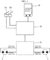
- the traveling control system for a construction machine in accordance with the embodiment of the present invention includes a first electric traveling pedal 11a, a second electric traveling pedal 11b, a traveling pattern input means 12, a controller 13 and a hydraulic circuit 14.
- the first electric traveling pedal 11a is configured to output a manipulation value of an electric signal in response to driver's manipulation and to thereby operate a first traveling motor 3 connected thereto.
- a first traveling motor 3 For example, when the first electric traveling pedal 11a is manipulated forward (on the basis of a posture of the driver sitting on a front driver seat) by the driver, the first traveling motor 3 rotates in a forward direction, and when the first electric traveling pedal 11a is manipulated backward, the first traveling motor 3 rotates in a reverse direction.
- the first traveling motor 3 is configured to be substantially driven by operating oil that is to be supplied from the hydraulic circuit 14 in accordance with the manipulation on the first electric traveling pedal 11a.
- the first traveling motor 3 may be a track motor configured to drive a crawler type track mounted on a lower traveling structure of an excavator, for example.
- the second electric traveling pedal 11b is configured to output a manipulation value of an electric signal in response to driver's manipulation and to thereby operate a second traveling motor 4 connected thereto.
- the second electric traveling pedal 11b is configured to control the second traveling motor 4 in the same manner as the first electric traveling pedal 11a. That is, when the second electric traveling pedal 11b is manipulated forward by the driver, the second traveling motor 4 rotates in a forward direction, and when the second electric traveling pedal 11b is manipulated backward, the second traveling motor 4 rotates in a reverse direction.
- the second traveling motor 4 is configured to be driven by operating oil that is to be supplied from the hydraulic circuit 14 in accordance with the manipulation on the second electric traveling pedal 11b, and may be a track motor.
- the traveling pattern input means 12 is equipped in an operator's cab. In this case, the traveling pattern input means 12 is preferably equipped at a position at which the driver sitting on the driver seat can perform manipulation with sitting on the driver seat.
- the traveling pattern input means 12 is configured to enable the driver to input a traveling pattern of the excavator. That is, the traveling pattern input means 12 is configured to enable the driver to select a traveling pattern of the excavator.
- an electric signal relating to the traveling pattern is transmitted to the controller 13 electrically connected to the traveling pattern input means 12.
- Table 1 shows traveling patterns that can be selected by the driver.
- the first traveling pattern is a traveling pattern for moving forward or backward the excavator in accordance with the manipulation on the first electric traveling pedal 11a and turning left or right the excavator in accordance with the manipulation on the second electric traveling pedal 11b.
- the second traveling pattern is a traveling pattern for turning left or right the excavator in accordance with the manipulation on the first electric traveling pedal 11a and moving forward or backward the excavator in accordance with the manipulation on the second electric traveling pedal 11b.
- the driver can select the corresponding traveling pattern.
- the excavator can be moved forward or backward with only one of the first electric traveling pedal 11a and the second electric traveling pedal 11b. Therefore, it is possible to increase driver's convenience and to more stably move forward or backward the excavator.
- the change in manipulation manner based on the traveling pattern selected by the driver and the corresponding operations of the first traveling motor 3 and the second traveling motor 4 are controlled by the controller 13, which will be described later in more detail.
- the traveling pattern may further include the third traveling pattern.
- the third traveling pattern is a traveling pattern for rotating the first traveling motor 3 in the forward or reverse direction in accordance with the manipulation on the first electric traveling pedal 11a and rotating the second traveling motor 4 in the forward or reverse direction in accordance with the manipulation on the second electric traveling pedal 11b.
- the traveling pattern may further include diverse traveling patterns so as to widen the options to be selected by the driver, in addition to the first to third traveling patterns.
- the traveling pattern input means 12 may have a display window so that the driver can select the traveling pattern.
- the first to third traveling patterns may be displayed as "setting 1", "setting 2" and "setting 3" on the display window of the traveling pattern input means 12.
- the display window may be configured by a touch panel so that icons relating to the traveling patterns displayed in this way can be touched and selected by the driver.
- the traveling pattern input means 12 may be provided with an icon selection button. In this case, the driver can select a desired traveling pattern by manipulating the icon selection button.
- the controller 13 is electrically connected to the first electric traveling pedal 11a, the second electric traveling pedal 11b and the traveling pattern input means 12.
- the controller 13 is configured to sense a manipulation value that is to be output from at least one of the first electric traveling pedal 11a and the second electric traveling pedal 11b.
- the controller 13 is configured to sense a traveling pattern that is to be input to the traveling pattern input means 12 by the driver.
- the controller 13 is configured to calculate command values required for operations of the first traveling motor 3 and the second traveling motor 4 in accordance with the input traveling pattern and to output the same to the hydraulic circuit 14 electrically connected thereto.
- the command values are defined as magnitudes of electric signals for determining degrees of switching of the traveling spools 6, 7 (refer to FIG. 7 ) provided to the hydraulic circuit 14.
- the controller 13 may include a memory unit 13a, a sensing unit 13b and a calculation unit 13c.
- the memory unit 13a a plurality of setting traveling patterns is stored.
- the plurality of setting traveling patterns is the first to third traveling patterns as shown in Table 1.
- the setting traveling patterns stored in the memory unit 13a are displayed on the display window of traveling pattern input means 12 so that the driver can select the same.
- the sensing unit 13b is configured to sense the manipulation values that are to be output from the first electric traveling pedal 11a and the second electric traveling pedal 11b and are to be transmitted as electric signals. Also, the sensing unit 13b is configured to sense a traveling pattern that is to be selected and input to the traveling pattern input means 12 by the driver and is to be transmitted as an electric signal by the traveling pattern input means 12.
- the calculation unit 13c is configured to compare the traveling pattern sensed by the sensing unit 13b and the plurality of setting traveling patterns stored in the memory unit 13a, to select a setting traveling pattern, which coincides with the sensed traveling pattern, of the plurality of setting traveling patterns, and to calculate the command values, i.e., the command values required for operations of the first traveling motor 3 and the second traveling motor 4 to be output to the hydraulic circuit 14 in accordance with the manipulation values of the first electric traveling pedal 11a and the second electric traveling pedal 11b sensed by the sensing unit 13b so that the first traveling motor 3 and the second traveling motor 4 are to be operated in accordance with the selected setting traveling pattern.
- the hydraulic circuit 14 is electrically connected to the controller 13. Thereby, the hydraulic circuit 14 is configured to control a flow rate and flow of operating oil to be supplied to the first traveling motor 3 and the second traveling motor 4 in accordance with the command values transmitted from the controller 13, thereby driving the first traveling motor 3 and the second traveling motor 4.
- the hydraulic circuit 14 has the same configuration and operation as the main control valve 8 configured to control a flow rate and flow of the operating oil that is to be discharged from the hydraulic pumps PI, P2 shown in FIG. 7 and is to be supplied to the left and right traveling motors 3, 4, the detailed description thereof is omitted.
- control method of the controller that is to be executed when the first traveling pattern is selected by the driver is described with reference to FIGS. 3 to 6 .
- the reference numerals of the respective configurations are denoted as shown in FIGS. 1 and 2 .
- the first traveling pattern is a traveling pattern for moving forward or backward the excavator in accordance with the manipulation on the first electric traveling pedal 11a and turning left or right the excavator in accordance with the manipulation on the second electric traveling pedal 11b.
- the controller 13 When the controller 13 senses the first traveling pattern input to the traveling pattern input means 12 by the driver and the manipulation value output as the first electric traveling pedal 11a is manipulated forward, the controller 13 calculates a first command value (a command value 1 to be input to the first traveling motor, in FIG. 3 ) required for operation of the first traveling motor 3, as shown in FIG. 3 . Also, the controller 13 calculates a second command value (a command value 1 to be input to the second traveling motor, in FIG. 4 ) required for operation of the second traveling motor 4, as shown in FIG. 4 . Then, the controller 13 transmits the first command value and the second command value to the hydraulic circuit 14 so as to operate the first traveling motor 3 and the second traveling motor 4.
- a first command value a command value 1 to be input to the first traveling motor, in FIG. 3
- a second command value a command value 1 to be input to the second traveling motor, in FIG. 4
- the controller 13 When the controller 13 senses the first traveling pattern input to the traveling pattern input means 12 by the driver and the manipulation value output as the second electric traveling pedal 11b is manipulated backward, the controller 13 calculates a third command value (a command value 2 to be input to the first traveling motor, in FIG. 5 ) required for operation of the first traveling motor 3, as shown in FIG. 5 . Also, the controller 13 calculates a fourth command value (a command value 2 to be input to the second traveling motor, in FIG. 6 ) required for operation of the second traveling motor 4, as shown in FIG. 6 . Then, the controller 13 transmits the third command value and the fourth command value to the hydraulic circuit 14 so as to operate the first traveling motor 3 and the second traveling motor 4.
- the first traveling motor 3 is rotated in the reverse direction and the second traveling motor 4 is rotated in the forward direction.
- the excavator is turned left.
- the excavator is turned right through the series of controls of the controller 13 as described above.
- the controller 13 When the controller 13 senses the first traveling pattern input to the traveling pattern input means 12 by the driver and the respective manipulation values output as a result of the simultaneous manipulation on the first electric traveling pedal 11a and the second electric traveling pedal 11b, the controller 13 calculates a fifth command value required for operation of the first traveling motor 3.
- the controller 13 calculates the fifth command value as a sum of the first command value and the third command value.
- the fifth command value calculated as a sum of the first command value and the third command value is a positive value
- the first traveling motor 3 is rotated in the forward direction
- the fifth command value when the fifth command value is a negative value, the first traveling motor 3 is rotated in the reverse direction.
- an electric signal having a magnitude corresponding to an absolute value of the fifth command value is transmitted from the controller 13 to the hydraulic circuit 14, so that the first traveling motor 3 is rotated at speed proportional to the electric signal having a magnitude corresponding to the absolute value of the fifth command value.
- the controller 13 calculates a sixth command value required for operation of the second traveling motor 4.
- the controller 13 selects, as the sixth command value, one of the second command value and the fourth command value. Since the second command value and the fourth command value are all values enabling the second traveling motor 4 to rotate in the forward direction, the controller 13 selects, as the sixth command value, a relatively larger command value of the second command value and the fourth command value.
- the controller 13 transmits the fifth command value and the sixth command value to the hydraulic circuit 14, thereby operating the first traveling motor 3 and the second traveling motor 4.
- the fifth command value and the sixth command value required for operations of the first traveling motor 3 and the second traveling motor 4 are determined in the above-described manner by the controller 13. Therefore, when the manipulation values of the first electric traveling pedal 11a and the second electric traveling pedal 11b are changed, the left and right turning speeds of the excavator can be adjusted. That is, when the first electric traveling pedal 11a and the second electric traveling pedal 11b are manipulated at the same time, a relative turning speed can be increased or decreased, as compared to the left turn or right turn of the excavator in accordance with the third command value and the fourth command value as a result of the single manipulation on the second electric traveling pedal 11b.
Landscapes
- Engineering & Computer Science (AREA)
- Mining & Mineral Resources (AREA)
- Civil Engineering (AREA)
- General Engineering & Computer Science (AREA)
- Structural Engineering (AREA)
- Operation Control Of Excavators (AREA)
Abstract
Description
- The present invention relates to a traveling control system for a construction machine and, more particularly, to a traveling control system for a construction machine capable of easily and rapidly changing diverse traveling patterns desired by a driver in connection with a construction machine equipped with electric traveling pedals, such as an excavator.
- In general, two traveling pedals are used for excavator traveling. In this case, one traveling pedal is used to control a left traveling motor and the other traveling pedal is used to control a right traveling motor. For forward or backward traveling, the two traveling pedals are manipulated forward or backward at the same time. However, the simultaneous manipulation on the two traveling pedals for forward or backward movement causes inconvenience to the driver. In particular, when the two traveling pedals are not manipulated by the same amount, the excavator turns left or right, instead of moving forward or backward. Therefore, an additional pedal referred to as a straight traveling pedal is usually equipped and used.
-
FIG. 7 is a circuit diagram depicting a hydraulic system for excavator traveling in accordance with the related art. - As shown in
FIG. 7 , the hydraulic system for excavator traveling in accordance with the related art includes a first hydraulic traveling pedal 1a, a second hydraulic traveling pedal 1b, a hydraulicstraight traveling pedal 2, a left travelingmotor 3, a right travelingmotor 4,shuttle valves 5a to 5d and amain control valve 8. Here, the first hydraulic traveling pedal 1a is configured to control the left travelingmotor 3, and the second hydraulic traveling pedal 1b is configured to control the right travelingmotor 4. Also, the hydraulic straight travelingpedal 2 is configured to control forward and backward traveling. Theshuttle valves 5a to 5d are configured to select a signal having a larger value from signals to be applied from the first hydraulic traveling pedal 1a and the second hydraulic traveling pedal 1b and a signal to be applied from the hydraulicstraight traveling pedal 2 and to transmit the same to travelingspools main control valve 8. - Operations of the hydraulic system for excavator traveling in accordance with the related art are described. A pilot signal pressure applied from the first hydraulic traveling pedal 1a switches the
traveling spool 6 via theshuttle valve 5a through apilot line 9. Thereby, operating oil discharged from a hydraulic pump P1 is supplied to the left travelingmotor 3 via thetraveling spool 6, so that the left travelingmotor 3 is driven. A method of driving the right travelingmotor 4 is also the same. - Here, in order to move forward or backward the excavator, the first hydraulic traveling pedal 1a and the second hydraulic traveling pedal 1b have only to be manipulated in the same direction at the same time. However, the simultaneous manipulation on the first hydraulic traveling pedal 1a and the second hydraulic traveling pedal 1b causes inconvenience to the driver. In particular, when manipulation amounts on the first hydraulic traveling pedal 1a and the second hydraulic traveling pedal 1b are not the same, the pilot signal pressures to be transmitted to the
respective traveling spools straight traveling pedal 2. A pilot signal pressure that is generated when manipulating the hydraulic straight travelingpedal 2 passes oneshuttle valve 5a and theother shuttle valve 5b through apilot line 10, so that therespective traveling spools motor 3 and the right travelingmotor 4. In this way, the excavator can move forward or backward. - Like this, according to the related art, it is possible to securely move forward or backward the excavator only when the additional straight traveling
pedal 2 is equipped. However, the cost of the equipment increases, and the hydraulic circuit for actuation becomes complicated, so that a quality problem such as oil leakage may also be caused. - The present invention has been made in view of the above situations, and an object thereof is to provide a traveling control system for a construction machine capable of easily and rapidly changing diverse traveling patterns desired by a driver in connection with a construction machine equipped with electric traveling pedals, such as an excavator.
- In order to achieve the above object, according to the present invention, there is provided a traveling control system for a construction machine including first and second electric traveling pedals configured to output manipulation values of electric signals in response to driver's manipulation and to thereby operate first and second traveling motors connected thereto, respectively; a traveling pattern input means equipped in an operator's cab so as to enable a driver to input a traveling pattern of the construction machine; a controller electrically connected to the first and second electric traveling pedals and the traveling pattern input means, and configured to sense the manipulation value to be output from at least one of the first and second electric traveling pedals and the traveling pattern to be input to the traveling pattern input means and to calculate and output command values required for operations of the first and second traveling motors in accordance with the input traveling pattern, and a hydraulic circuit electrically connected to the controller and configured to control a flow rate and flow of operating oil to be supplied to the first and second traveling motors in accordance with the command values to be transmitted from the controller, thereby driving the first and second traveling motors.
- The controller may include a memory unit in which a plurality of setting traveling patterns is to be stored, a sensing unit configured to sense the manipulation values and the traveling pattern, and a calculation unit configured to compare the sensed traveling pattern and the plurality of setting traveling patterns and to calculate the command values to be output to the hydraulic circuit in accordance with the sensed manipulation values so that the first and second traveling motors are to be operated in accordance with a setting traveling pattern, which coincides with the sensed traveling pattern, of the plurality of setting traveling patterns.
- Also, the traveling pattern may include a first traveling pattern for moving forward or backward the construction machine in accordance with manipulation on the first electric traveling pedal and turning left or right the construction machine in accordance with manipulation on the second electric traveling pedal.
- When the controller senses the first traveling pattern input to the traveling pattern input means and the manipulation value output from the first electric traveling pedal, the controller may calculate a first command value required for the operation of the first traveling motor and a second command value required for the operation of the second traveling motor and transmit the same to the hydraulic circuit, thereby moving forward or backward the construction machine.
- Also, when the controller senses the first traveling pattern input to the traveling pattern input means and the manipulation value output from the second electric traveling pedal, the controller may calculate a third command value required for the operation of the first traveling motor and a fourth command value required for the operation of the second traveling motor and transmit the same to the hydraulic circuit, thereby turning left or right the construction machine.
- When the controller senses the first traveling pattern input to the traveling pattern input means and the manipulation values output from each of the first and second electric traveling pedals, the controller may calculate a fifth command value required for the operation of the first traveling motor and a sixth command value required for the operation of the second traveling motor and transmit the same to the hydraulic circuit, thereby turning left or right the construction machine, a relative turning speed thereof being increased or decreased as compared to the left turn or right turn of the construction machine in accordance with the third command value and the fourth command value.
- The fifth command value may be a sum of the first command value and the third command value.
- Also, when the sum of the first command value and the third command value is a positive value, the first traveling motor may rotate in a forward direction, and when the sum is a negative value, the first traveling motor may rotate in a reverse direction.
- An electric signal having a magnitude corresponding to an absolute value of the fifth command value may be transmitted from the controller to the hydraulic circuit.
- As the sixth command value, a relatively larger command value of the second command value and the fourth command value may be selected.
- According to the present invention, the traveling pattern input means for enabling the driver to select the traveling pattern of the construction machine, such as an excavator and the controller configured to calculate and output the command values required for operations of the traveling motors in accordance with the traveling pattern input from the traveling pattern input means are provided. Therefore, it is possible to easily and rapidly change the diverse traveling patterns desired by the driver in connection with the excavator. In particular, it is possible to move forward or backward the excavator with only one traveling pedal, so that it is possible to increase driver's convenience and to secure traveling stability.
- Also, according to the present invention, it is not necessary to provide a separate straight traveling pedal, unlike the related art, so that it is possible to suppress the additional cost increase of the construction machine.
-
-
FIG. 1 is a schematic configuration view depicting a traveling control system for a construction machine in accordance with an embodiment of the present invention. -
FIG. 2 is a configuration view depicting a controller of the traveling control system for a construction machine in accordance with the embodiment of the present invention. -
FIGS. 3 to 6 are graphs showing command values required for operations of traveling motors in accordance with manipulation values of electric traveling pedals. -
FIG. 7 is a circuit diagram depicting a hydraulic system for excavator traveling in accordance with the related art. - Hereinafter, a traveling control system for a construction machine in accordance with an embodiment of the present invention will be described in detail with reference to the accompanying drawings.
- When describing the present invention, the specific descriptions of the related well-known functions or configurations will be omitted if it is considered that the descriptions make the gist of the present invention unclear.
- A traveling control system for a construction machine in accordance with an embodiment of the present invention is a system for controlling traveling such as forward movement, backward movement, left turn and right turn of a construction machine, for example, an excavator. As shown in
FIG. 1 , the traveling control system for a construction machine in accordance with the embodiment of the present invention includes a firstelectric traveling pedal 11a, a secondelectric traveling pedal 11b, a traveling pattern input means 12, acontroller 13 and ahydraulic circuit 14. - The first
electric traveling pedal 11a is configured to output a manipulation value of an electric signal in response to driver's manipulation and to thereby operate a first travelingmotor 3 connected thereto. For example, when the firstelectric traveling pedal 11a is manipulated forward (on the basis of a posture of the driver sitting on a front driver seat) by the driver, thefirst traveling motor 3 rotates in a forward direction, and when the firstelectric traveling pedal 11a is manipulated backward, the first travelingmotor 3 rotates in a reverse direction. Here, the first travelingmotor 3 is configured to be substantially driven by operating oil that is to be supplied from thehydraulic circuit 14 in accordance with the manipulation on the firstelectric traveling pedal 11a. The first travelingmotor 3 may be a track motor configured to drive a crawler type track mounted on a lower traveling structure of an excavator, for example. - The second
electric traveling pedal 11b is configured to output a manipulation value of an electric signal in response to driver's manipulation and to thereby operate a second travelingmotor 4 connected thereto. The secondelectric traveling pedal 11b is configured to control the second travelingmotor 4 in the same manner as the firstelectric traveling pedal 11a. That is, when the secondelectric traveling pedal 11b is manipulated forward by the driver, the second travelingmotor 4 rotates in a forward direction, and when the secondelectric traveling pedal 11b is manipulated backward, the second travelingmotor 4 rotates in a reverse direction. Like the first travelingmotor 3, the second travelingmotor 4 is configured to be driven by operating oil that is to be supplied from thehydraulic circuit 14 in accordance with the manipulation on the secondelectric traveling pedal 11b, and may be a track motor. - The traveling pattern input means 12 is equipped in an operator's cab. In this case, the traveling pattern input means 12 is preferably equipped at a position at which the driver sitting on the driver seat can perform manipulation with sitting on the driver seat. The traveling pattern input means 12 is configured to enable the driver to input a traveling pattern of the excavator. That is, the traveling pattern input means 12 is configured to enable the driver to select a traveling pattern of the excavator. When the driver selects a desired traveling pattern with the traveling pattern input means 12, an electric signal relating to the traveling pattern is transmitted to the
controller 13 electrically connected to the traveling pattern input means 12.[Table 1] Manipulation direction First traveling pattern Second traveling pattern Third traveling pattern First electric traveling pedal: forward Excavator: forward movement Excavator: right turn First traveling motor: forward direction First electric traveling pedal: backward Excavator: backward movement Excavator: left turn First traveling motor: reverse direction Second electric traveling pedal: forward Excavator: left turn Excavator: forward movement Second traveling motor: forward direction Second electric traveling pedal: backward Excavator: right turn Excavator: backward movement Second traveling motor: reverse direction - Table 1 shows traveling patterns that can be selected by the driver. As shown in Table 1, the first traveling pattern is a traveling pattern for moving forward or backward the excavator in accordance with the manipulation on the first electric traveling pedal 11a and turning left or right the excavator in accordance with the manipulation on the second electric traveling pedal 11b. Also, the second traveling pattern is a traveling pattern for turning left or right the excavator in accordance with the manipulation on the first electric traveling pedal 11a and moving forward or backward the excavator in accordance with the manipulation on the second electric traveling pedal 11b. That is, since the manipulation manners of the first electric traveling pedal 11a and the second electric traveling pedal 11b are determined depending on the traveling pattern, when there are the manipulation manners of the first electric traveling pedal 11a and the second electric traveling pedal 11b desired by the driver, the driver can select the corresponding traveling pattern. As can be seen from the first traveling pattern and the second traveling pattern in Table 1, the excavator can be moved forward or backward with only one of the first electric traveling pedal 11a and the second electric traveling pedal 11b. Therefore, it is possible to increase driver's convenience and to more stably move forward or backward the excavator. Like this, the change in manipulation manner based on the traveling pattern selected by the driver and the corresponding operations of the first traveling
motor 3 and the second travelingmotor 4 are controlled by thecontroller 13, which will be described later in more detail. - In the meantime, as shown in Table 1, the traveling pattern may further include the third traveling pattern. The third traveling pattern is a traveling pattern for rotating the first traveling
motor 3 in the forward or reverse direction in accordance with the manipulation on the first electric traveling pedal 11a and rotating the second travelingmotor 4 in the forward or reverse direction in accordance with the manipulation on the second electric traveling pedal 11b. The traveling pattern may further include diverse traveling patterns so as to widen the options to be selected by the driver, in addition to the first to third traveling patterns. - The traveling pattern input means 12 may have a display window so that the driver can select the traveling pattern. In this case, as shown in
FIG. 1 , the first to third traveling patterns may be displayed as "setting 1", "setting 2" and "setting 3" on the display window of the traveling pattern input means 12. The display window may be configured by a touch panel so that icons relating to the traveling patterns displayed in this way can be touched and selected by the driver. Also, the traveling pattern input means 12 may be provided with an icon selection button. In this case, the driver can select a desired traveling pattern by manipulating the icon selection button. - The
controller 13 is electrically connected to the first electric traveling pedal 11a, the second electric traveling pedal 11b and the traveling pattern input means 12. Thecontroller 13 is configured to sense a manipulation value that is to be output from at least one of the first electric traveling pedal 11a and the second electric traveling pedal 11b. Also, thecontroller 13 is configured to sense a traveling pattern that is to be input to the traveling pattern input means 12 by the driver. Thecontroller 13 is configured to calculate command values required for operations of the first travelingmotor 3 and the second travelingmotor 4 in accordance with the input traveling pattern and to output the same to thehydraulic circuit 14 electrically connected thereto. In the embodiment of the present invention, the command values are defined as magnitudes of electric signals for determining degrees of switching of the travelingspools 6, 7 (refer toFIG. 7 ) provided to thehydraulic circuit 14. - To this end, as shown in
FIG. 2 , according to the embodiment of the present invention, thecontroller 13 may include amemory unit 13a, asensing unit 13b and acalculation unit 13c. - In the
memory unit 13a, a plurality of setting traveling patterns is stored. Here, the plurality of setting traveling patterns is the first to third traveling patterns as shown in Table 1. The setting traveling patterns stored in thememory unit 13a are displayed on the display window of traveling pattern input means 12 so that the driver can select the same. - The
sensing unit 13b is configured to sense the manipulation values that are to be output from the first electric traveling pedal 11a and the second electric traveling pedal 11b and are to be transmitted as electric signals. Also, thesensing unit 13b is configured to sense a traveling pattern that is to be selected and input to the traveling pattern input means 12 by the driver and is to be transmitted as an electric signal by the traveling pattern input means 12. - The
calculation unit 13c is configured to compare the traveling pattern sensed by thesensing unit 13b and the plurality of setting traveling patterns stored in thememory unit 13a, to select a setting traveling pattern, which coincides with the sensed traveling pattern, of the plurality of setting traveling patterns, and to calculate the command values, i.e., the command values required for operations of the first travelingmotor 3 and the second travelingmotor 4 to be output to thehydraulic circuit 14 in accordance with the manipulation values of the first electric traveling pedal 11a and the second electric traveling pedal 11b sensed by thesensing unit 13b so that the first travelingmotor 3 and the second travelingmotor 4 are to be operated in accordance with the selected setting traveling pattern. - The
hydraulic circuit 14 is electrically connected to thecontroller 13. Thereby, thehydraulic circuit 14 is configured to control a flow rate and flow of operating oil to be supplied to the first travelingmotor 3 and the second travelingmotor 4 in accordance with the command values transmitted from thecontroller 13, thereby driving the first travelingmotor 3 and the second travelingmotor 4. Here, since thehydraulic circuit 14 has the same configuration and operation as themain control valve 8 configured to control a flow rate and flow of the operating oil that is to be discharged from the hydraulic pumps PI, P2 shown inFIG. 7 and is to be supplied to the left and right travelingmotors - In the below, the control method of the controller that is to be executed when the first traveling pattern is selected by the driver is described with reference to
FIGS. 3 to 6 . The reference numerals of the respective configurations are denoted as shown inFIGS. 1 and2 . - In Examples of the present invention, the first traveling pattern is a traveling pattern for moving forward or backward the excavator in accordance with the manipulation on the first electric traveling pedal 11a and turning left or right the excavator in accordance with the manipulation on the second electric traveling pedal 11b.
- When the
controller 13 senses the first traveling pattern input to the traveling pattern input means 12 by the driver and the manipulation value output as the first electric traveling pedal 11a is manipulated forward, thecontroller 13 calculates a first command value (acommand value 1 to be input to the first traveling motor, inFIG. 3 ) required for operation of the first travelingmotor 3, as shown inFIG. 3 . Also, thecontroller 13 calculates a second command value (acommand value 1 to be input to the second traveling motor, inFIG. 4 ) required for operation of the second travelingmotor 4, as shown inFIG. 4 . Then, thecontroller 13 transmits the first command value and the second command value to thehydraulic circuit 14 so as to operate the first travelingmotor 3 and the second travelingmotor 4. In this case, since the first travelingmotor 3 and the second travelingmotor 4 are all rotated in the forward direction and the manipulation on the second electric traveling pedal 11b has not been sensed, the excavator is moved forward. On the contrary, when the first electric traveling pedal 11a is manipulated backward, the excavator is moved backward through the series of controls of thecontroller 13 as described above. - When the
controller 13 senses the first traveling pattern input to the traveling pattern input means 12 by the driver and the manipulation value output as the second electric traveling pedal 11b is manipulated backward, thecontroller 13 calculates a third command value (acommand value 2 to be input to the first traveling motor, inFIG. 5 ) required for operation of the first travelingmotor 3, as shown inFIG. 5 . Also, thecontroller 13 calculates a fourth command value (acommand value 2 to be input to the second traveling motor, inFIG. 6 ) required for operation of the second travelingmotor 4, as shown inFIG. 6 . Then, thecontroller 13 transmits the third command value and the fourth command value to thehydraulic circuit 14 so as to operate the first travelingmotor 3 and the second travelingmotor 4. In this case, the first travelingmotor 3 is rotated in the reverse direction and the second travelingmotor 4 is rotated in the forward direction. By the rotations of the first travelingmotor 3 and the second travelingmotor 4, the excavator is turned left. On the contrary, when the second electric traveling pedal 11b is manipulated backward, the excavator is turned right through the series of controls of thecontroller 13 as described above. - When the
controller 13 senses the first traveling pattern input to the traveling pattern input means 12 by the driver and the respective manipulation values output as a result of the simultaneous manipulation on the first electric traveling pedal 11a and the second electric traveling pedal 11b, thecontroller 13 calculates a fifth command value required for operation of the first travelingmotor 3. Here, thecontroller 13 calculates the fifth command value as a sum of the first command value and the third command value. In this case, when the fifth command value calculated as a sum of the first command value and the third command value is a positive value, the first travelingmotor 3 is rotated in the forward direction, and when the fifth command value is a negative value, the first travelingmotor 3 is rotated in the reverse direction. At this time, an electric signal having a magnitude corresponding to an absolute value of the fifth command value is transmitted from thecontroller 13 to thehydraulic circuit 14, so that the first travelingmotor 3 is rotated at speed proportional to the electric signal having a magnitude corresponding to the absolute value of the fifth command value. - Also, the
controller 13 calculates a sixth command value required for operation of the second travelingmotor 4. Here, thecontroller 13 selects, as the sixth command value, one of the second command value and the fourth command value. Since the second command value and the fourth command value are all values enabling the second travelingmotor 4 to rotate in the forward direction, thecontroller 13 selects, as the sixth command value, a relatively larger command value of the second command value and the fourth command value. - Then, the
controller 13 transmits the fifth command value and the sixth command value to thehydraulic circuit 14, thereby operating the first travelingmotor 3 and the second travelingmotor 4. - As described above, when the first electric traveling pedal 11a and the second electric traveling pedal 11b are manipulated at the same time, the fifth command value and the sixth command value required for operations of the first traveling
motor 3 and the second travelingmotor 4 are determined in the above-described manner by thecontroller 13. Therefore, when the manipulation values of the first electric traveling pedal 11a and the second electric traveling pedal 11b are changed, the left and right turning speeds of the excavator can be adjusted. That is, when the first electric traveling pedal 11a and the second electric traveling pedal 11b are manipulated at the same time, a relative turning speed can be increased or decreased, as compared to the left turn or right turn of the excavator in accordance with the third command value and the fourth command value as a result of the single manipulation on the second electric traveling pedal 11b. - Although the present invention has been described with reference to the specific embodiments and the drawings, the present invention is not limited to the embodiments, and a variety of variations and modifications can be made by one skilled in the art of the present invention.
- Therefore, the scope of the present invention should not be defined by the above-described embodiments but should be defined by the appended claims and equivalents thereof.
Claims (10)
- A traveling control system for a construction machine comprising:first and second electric traveling pedals configured to output manipulation values of electric signals in response to driver's manipulation and to thereby operate first and second traveling motors connected thereto, respectively;a traveling pattern input means equipped in an operator's cab so as to enable a driver to input a traveling pattern of the construction machine;a controller electrically connected to the first and second electric traveling pedals and the traveling pattern input means, and configured to sense the manipulation value to be output from at least one of the first and second electric traveling pedals and the traveling pattern to be input to the traveling pattern input means and to calculate and output command values required for operations of the first and second traveling motors in accordance with the input traveling pattern, anda hydraulic circuit electrically connected to the controller and configured to control a flow rate and flow of operating oil to be supplied to the first and second traveling motors in accordance with the command values to be transmitted from the controller, thereby driving the first and second traveling motors.
- The traveling control system for a construction machine according to Claim 1, wherein the controller comprises:a memory unit in which a plurality of setting traveling patterns is to be stored,a sensing unit configured to sense the manipulation values and the traveling pattern, anda calculation unit configured to compare the sensed traveling pattern and the plurality of setting traveling patterns and to calculate the command values to be output to the hydraulic circuit in accordance with the sensed manipulation values so that the first and second traveling motors are to be operated in accordance with a setting traveling pattern, which coincides with the sensed traveling pattern, of the plurality of setting traveling patterns.
- The traveling control system for a construction machine according to Claim 1, wherein the traveling pattern comprises a first traveling pattern for moving forward or backward the construction machine in accordance with manipulation on the first electric traveling pedal and turning left or right the construction machine in accordance with manipulation on the second electric traveling pedal.
- The traveling control system for a construction machine according to Claim 3, wherein when the controller senses the first traveling pattern input to the traveling pattern input means and the manipulation value output from the first electric traveling pedal, the controller calculates a first command value required for the operation of the first traveling motor and a second command value required for the operation of the second traveling motor and transmits the same to the hydraulic circuit, thereby moving forward or backward the construction machine.
- The traveling control system for a construction machine according to Claim 4, wherein when the controller senses the first traveling pattern input to the traveling pattern input means and the manipulation value output from the second electric traveling pedal, the controller calculates a third command value required for the operation of the first traveling motor and a fourth command value required for the operation of the second traveling motor and transmits the same to the hydraulic circuit, thereby turning left or right the construction machine.
- The traveling control system for a construction machine according to Claim 5, wherein when the controller senses the first traveling pattern input to the traveling pattern input means and the manipulation values output from each of the first and second electric traveling pedals, the controller calculates a fifth command value required for the operation of the first traveling motor and a sixth command value required for the operation of the second traveling motor and transmits the same to the hydraulic circuit, thereby turning left or right the construction machine, a relative turning speed thereof being increased or decreased as compared to the left turn or right turn of the construction machine in accordance with the third command value and the fourth command value.
- The traveling control system for a construction machine according to Claim 6, wherein the fifth command value is a sum of the first command value and the third command value.
- The traveling control system for a construction machine according to Claim 7, wherein when the sum of the first command value and the third command value is a positive value, the first traveling motor rotates in a forward direction, and when the sum is a negative value, the first traveling motor rotates in a reverse direction.
- The traveling control system for a construction machine according to Claim 8, wherein an electric signal having a magnitude corresponding to an absolute value of the fifth command value is transmitted from the controller to the hydraulic circuit.
- The traveling control system for a construction machine according to Claim 6, wherein as the sixth command value, a relatively larger command value of the second command value and the fourth command value is selected.
Applications Claiming Priority (1)
| Application Number | Priority Date | Filing Date | Title |
|---|---|---|---|
| PCT/KR2016/011812 WO2018074629A1 (en) | 2016-10-20 | 2016-10-20 | Construction machine traveling control system |
Publications (2)
| Publication Number | Publication Date |
|---|---|
| EP3540127A1 true EP3540127A1 (en) | 2019-09-18 |
| EP3540127A4 EP3540127A4 (en) | 2020-11-04 |
Family
ID=62018594
Family Applications (1)
| Application Number | Title | Priority Date | Filing Date |
|---|---|---|---|
| EP16919281.2A Withdrawn EP3540127A4 (en) | 2016-10-20 | 2016-10-20 | Construction machine traveling control system |
Country Status (4)
| Country | Link |
|---|---|
| US (1) | US11692333B2 (en) |
| EP (1) | EP3540127A4 (en) |
| CN (1) | CN110199066A (en) |
| WO (1) | WO2018074629A1 (en) |
Families Citing this family (1)
| Publication number | Priority date | Publication date | Assignee | Title |
|---|---|---|---|---|
| KR102463856B1 (en) * | 2017-03-30 | 2022-11-03 | 스미토모 겐키 가부시키가이샤 | shovel |
Family Cites Families (67)
| Publication number | Priority date | Publication date | Assignee | Title |
|---|---|---|---|---|
| US3357509A (en) * | 1963-01-31 | 1967-12-12 | Bofors Ab | Steering device for a track laying vehicle |
| BE793325A (en) * | 1971-12-27 | 1973-06-27 | Caterpillar Tractor Co | Hydraulic drive and steering system for tracked type vehicles. |
| US3990527A (en) * | 1975-05-21 | 1976-11-09 | Kabushiki Kaisha Komatsu Seisakusho | Steering apparatus for a vehicle of the type having revolving upper body with respect to a lower body thereof |
| GB1558604A (en) * | 1976-07-07 | 1980-01-09 | Inst Cercetare Si Proiectare T | Skid-steer loader |
| US4163413A (en) * | 1978-02-09 | 1979-08-07 | Caterpillar Tractor Co. | Vehicle control system |
| DE2943519A1 (en) * | 1979-10-27 | 1981-05-07 | Volkswagenwerk Ag | DRIVE FOR A VEHICLE WITH AN INTERNAL COMBUSTION ENGINE AND AN ELECTRIC MOTOR |
| US4457387A (en) * | 1980-05-19 | 1984-07-03 | Vickers, Incorporated | Hydraulic steering system for full-track vehicles |
| DE3801874A1 (en) * | 1988-01-12 | 1989-07-20 | Ortopedia Gmbh | ELECTRIC WHEELCHAIR |
| US4841841A (en) * | 1988-06-27 | 1989-06-27 | General Motors Corporation | Steer mechanism for a steer-by-driving vehicle |
| US5002454A (en) * | 1988-09-08 | 1991-03-26 | Caterpillar Inc. | Intuitive joystick control for a work implement |
| EP0612891A4 (en) * | 1991-11-06 | 1995-11-29 | Komatsu Mfg Co Ltd | Automatic greasing system for construction machines and abnormality detecting method therefor. |
| US5285861A (en) * | 1992-08-27 | 1994-02-15 | Kabushiki Kaisha Komatsu Seisakusho | Steering device of crawler type vehicle |
| FR2747432B1 (en) * | 1996-04-16 | 1998-06-26 | Rexroth Sigma | SINGLE LEVER DIRECTIONAL CONTROL HYDRAULIC DEVICE FOR VEHICLE |
| US5934397A (en) * | 1997-01-28 | 1999-08-10 | Schaper; Douglas | Modular land vehicle |
| DE19858958B4 (en) * | 1997-12-12 | 2006-08-17 | Komatsu Ltd. | Device for controlling several oil-hydraulic motors and a clutch |
| US6148939A (en) * | 1998-12-22 | 2000-11-21 | Caterpillar Inc. | Variable gain steering control system for a work machine |
| EP1125781B1 (en) * | 2000-01-24 | 2004-03-24 | Hino Jidosha Kabushiki Kaisha | Hybrid vehicle |
| JP3569210B2 (en) * | 2000-08-11 | 2004-09-22 | 本田技研工業株式会社 | Power transmission device for hybrid vehicle and control method therefor |
| US6684969B1 (en) * | 2001-04-26 | 2004-02-03 | Electric Mobility Corporation | Changeable personal mobility vehicle |
| JP3817516B2 (en) * | 2002-12-26 | 2006-09-06 | 本田技研工業株式会社 | Drive control apparatus for hybrid vehicle |
| JP4386265B2 (en) * | 2004-03-19 | 2009-12-16 | 日立建機株式会社 | Construction machine operation pattern switching device and construction machine operation pattern switching system |
| US7137919B2 (en) * | 2004-11-18 | 2006-11-21 | General Motors Corporation | Planetary dual power path transmission with electric motors |
| JP2006306199A (en) | 2005-04-27 | 2006-11-09 | Shin Caterpillar Mitsubishi Ltd | Travel drive control device for work machine |
| KR101157267B1 (en) | 2005-12-28 | 2012-07-03 | 두산인프라코어 주식회사 | Hydraulic control system for a travel-combined-operation of en excavator |
| US20080119985A1 (en) * | 2006-10-30 | 2008-05-22 | Schubitzke Edward D | Controller sense inverter for powered vehicles having a rotating turret |
| US8177679B2 (en) * | 2007-01-31 | 2012-05-15 | Toyota Jidosha Kabushiki Kaisha | Control device for vehicular drive system |
| JP2008207690A (en) * | 2007-02-27 | 2008-09-11 | Toyota Motor Corp | Control device for vehicle drive device |
| US20080243322A1 (en) * | 2007-03-30 | 2008-10-02 | Mazda Motor Corporation | Control device and method of hybrid vehicle |
| JP4591472B2 (en) * | 2007-04-13 | 2010-12-01 | トヨタ自動車株式会社 | Control device for drive device for hybrid vehicle |
| JP5104169B2 (en) * | 2007-09-28 | 2012-12-19 | トヨタ自動車株式会社 | Control device for vehicle power transmission device |
| JP5496454B2 (en) * | 2007-11-29 | 2014-05-21 | 日産自動車株式会社 | Control device for hybrid vehicle |
| US20090198414A1 (en) * | 2008-01-31 | 2009-08-06 | Caterpillar Inc. | Operator interface for controlling a vehicle |
| US20100099532A1 (en) * | 2008-10-20 | 2010-04-22 | Cashen Wilhelm A | Hybrid drive method and apparatus |
| KR20110055998A (en) | 2009-11-20 | 2011-05-26 | 볼보 컨스트럭션 이큅먼트 에이비 | Driving and turning device of construction machinery |
| KR101648979B1 (en) | 2009-12-08 | 2016-08-18 | 두산인프라코어 주식회사 | Hydraulic circuit for construction machinery |
| EP2636566B1 (en) * | 2010-11-04 | 2019-05-01 | Toyota Jidosha Kabushiki Kaisha | Hybrid drive device for vehicle |
| JP5767238B2 (en) * | 2010-11-04 | 2015-08-19 | トヨタ自動車株式会社 | Hybrid drive device for vehicle |
| US9102322B2 (en) * | 2010-11-04 | 2015-08-11 | Toyota Jidosha Kabushiki Kaisha | Control apparatus for hybrid vehicle |
| US8985263B2 (en) * | 2011-03-01 | 2015-03-24 | Joy Mm Delaware, Inc. | Seat module for a mining vehicle |
| JP5633641B2 (en) * | 2011-04-27 | 2014-12-03 | トヨタ自動車株式会社 | Vehicle control device |
| US9221454B2 (en) * | 2011-12-28 | 2015-12-29 | Toyota Jidosha Kabushiki Kaisha | Control system of a vehicle |
| EP2798126B1 (en) * | 2011-12-29 | 2019-08-07 | Clark Equipment Company | Electronic tag along |
| US9518655B2 (en) * | 2013-01-29 | 2016-12-13 | Deere & Company | Continuously adjustable control management for a hydraulic track system |
| CN105026654A (en) | 2013-02-08 | 2015-11-04 | 沃尔沃建造设备有限公司 | Construction equipment driving control method |
| US8979694B2 (en) * | 2013-02-22 | 2015-03-17 | GM Global Technology Operations LLC | Hybrid vehicle with power-split and parallel hybrid transmission and method of controlling same |
| CN105102729B (en) * | 2013-11-15 | 2017-03-08 | 株式会社小松制作所 | Working truck and its control method |
| JP6265725B2 (en) * | 2013-12-16 | 2018-01-24 | 株式会社小松製作所 | Work vehicle and control method of work vehicle |
| JP6265726B2 (en) * | 2013-12-16 | 2018-01-24 | 株式会社小松製作所 | Work vehicle and control method of work vehicle |
| US20160340868A1 (en) | 2014-01-27 | 2016-11-24 | Volvo Construction Equipment Ab | Travelling control device for construction machine and control method thereof |
| EP3012165A4 (en) * | 2014-01-27 | 2017-04-26 | Komatsu Ltd. | Work vehicle and method for emergency running of work vehicle |
| US9604668B2 (en) * | 2014-07-14 | 2017-03-28 | Caterpillar Forest Products Inc. | Control system for switching traction device inputs |
| GB2531766A (en) * | 2014-10-29 | 2016-05-04 | Bamford Excavators Ltd | Working Machine |
| WO2016108457A1 (en) * | 2015-01-04 | 2016-07-07 | 김의한 | Hybrid transmission having fixed gear shift stage |
| US20170370446A1 (en) * | 2015-02-17 | 2017-12-28 | Oshkosh Corporation | Inline electromechanical variable transmission system |
| US9656659B2 (en) * | 2015-02-17 | 2017-05-23 | Oshkosh Corporation | Multi-mode electromechanical variable transmission |
| US10220836B2 (en) * | 2015-02-19 | 2019-03-05 | Honda Motor Co., Ltd. | Vehicle |
| US9840140B1 (en) * | 2016-08-05 | 2017-12-12 | GM Global Technology Operations LLC | Compound-power-split electrically variable transmissions with motor clutching devices |
| US12227257B2 (en) * | 2017-04-01 | 2025-02-18 | Razor Usa Llc | Electric balance vehicles |
| JP6915501B2 (en) * | 2017-11-08 | 2021-08-04 | トヨタ自動車株式会社 | Vehicle control device |
| JP7152163B2 (en) * | 2018-02-14 | 2022-10-12 | 株式会社小松製作所 | WORK VEHICLE AND CONTROL METHOD FOR WORK VEHICLE |
| JP7156806B2 (en) * | 2018-02-23 | 2022-10-19 | 株式会社小松製作所 | WORK VEHICLE AND CONTROL METHOD FOR WORK VEHICLE |
| JP6924159B2 (en) * | 2018-02-23 | 2021-08-25 | 株式会社小松製作所 | Work vehicle and control method of work vehicle |
| JP7160539B2 (en) * | 2018-02-23 | 2022-10-25 | 株式会社小松製作所 | WORK VEHICLE AND CONTROL METHOD FOR WORK VEHICLE |
| US10774504B2 (en) * | 2018-06-22 | 2020-09-15 | Caterpillar Forest Products Inc. | Input-output control mapping with corresponding splash screen |
| US20210010240A1 (en) * | 2019-07-09 | 2021-01-14 | Cnh Industrial America Llc | System and method for controlling the operation of a work vehicle based on a desired turning radius |
| JP7196801B2 (en) * | 2019-09-09 | 2022-12-27 | トヨタ自動車株式会社 | electric vehicle |
| CN115195686B (en) * | 2021-04-07 | 2024-08-02 | 汉拿万都株式会社 | Braking device |
-
2016
- 2016-10-20 EP EP16919281.2A patent/EP3540127A4/en not_active Withdrawn
- 2016-10-20 WO PCT/KR2016/011812 patent/WO2018074629A1/en not_active Ceased
- 2016-10-20 US US16/342,702 patent/US11692333B2/en active Active
- 2016-10-20 CN CN201680090230.9A patent/CN110199066A/en active Pending
Also Published As
| Publication number | Publication date |
|---|---|
| CN110199066A (en) | 2019-09-03 |
| US11692333B2 (en) | 2023-07-04 |
| WO2018074629A1 (en) | 2018-04-26 |
| EP3540127A4 (en) | 2020-11-04 |
| US20190345693A1 (en) | 2019-11-14 |
Similar Documents
| Publication | Publication Date | Title |
|---|---|---|
| US8146355B2 (en) | Traveling device for crawler type heavy equipment | |
| EP2098437B1 (en) | Steering system for working vehicle | |
| US9951797B2 (en) | Work machine | |
| JP5390875B2 (en) | Work vehicle, control method of work vehicle, and calibration method of swash plate sensor of hydraulic pump in work vehicle | |
| CN109844230B (en) | Construction machine | |
| JP6438312B2 (en) | Electric operating device of hydraulic work machine | |
| EP3216927B1 (en) | Driving straight ahead device for construction machine and control method therefor | |
| US9643648B2 (en) | Single pedal propulsion system for straight travel of work vehicle | |
| JPH04870B2 (en) | ||
| EP3317463B1 (en) | Travel control system of construction machine | |
| US11692333B2 (en) | Construction machine traveling control system | |
| KR101846030B1 (en) | control device for construction machine | |
| US20180238026A1 (en) | Construction machine and method for controlling construction machine | |
| JP2016020105A (en) | Hydraulic drive system | |
| JP6871669B2 (en) | Travel control device in construction machinery | |
| US11913195B2 (en) | Hydraulic machine | |
| EP2325401A1 (en) | Traveling and turning device for construction machine | |
| JP2006306199A (en) | Travel drive control device for work machine | |
| KR20040094186A (en) | construction equipment travel control device and its method | |
| KR20130084071A (en) | Travel system of construction machine and method thereof | |
| JP2004100711A (en) | Lever operation pattern switching device | |
| KR20170077537A (en) | Control system and method for hydraulic motor in working equipment | |
| JP2013249886A (en) | Construction machine | |
| JPH05248406A (en) | Running speed control method for construction machinery | |
| JP2008189456A (en) | Operation switching device and mode switching device for data communicating system for industrial vehicle |
Legal Events
| Date | Code | Title | Description |
|---|---|---|---|
| STAA | Information on the status of an ep patent application or granted ep patent |
Free format text: STATUS: THE INTERNATIONAL PUBLICATION HAS BEEN MADE |
|
| PUAI | Public reference made under article 153(3) epc to a published international application that has entered the european phase |
Free format text: ORIGINAL CODE: 0009012 |
|
| STAA | Information on the status of an ep patent application or granted ep patent |
Free format text: STATUS: REQUEST FOR EXAMINATION WAS MADE |
|
| 17P | Request for examination filed |
Effective date: 20190516 |
|
| AK | Designated contracting states |
Kind code of ref document: A1 Designated state(s): AL AT BE BG CH CY CZ DE DK EE ES FI FR GB GR HR HU IE IS IT LI LT LU LV MC MK MT NL NO PL PT RO RS SE SI SK SM TR |
|
| AX | Request for extension of the european patent |
Extension state: BA ME |
|
| DAV | Request for validation of the european patent (deleted) | ||
| DAX | Request for extension of the european patent (deleted) | ||
| A4 | Supplementary search report drawn up and despatched |
Effective date: 20201002 |
|
| RIC1 | Information provided on ipc code assigned before grant |
Ipc: E02F 9/22 20060101AFI20200928BHEP |
|
| STAA | Information on the status of an ep patent application or granted ep patent |
Free format text: STATUS: THE APPLICATION IS DEEMED TO BE WITHDRAWN |
|
| 18D | Application deemed to be withdrawn |
Effective date: 20210501 |