EP3539898A2 - Träger für behälter - Google Patents
Träger für behälter Download PDFInfo
- Publication number
- EP3539898A2 EP3539898A2 EP19161992.3A EP19161992A EP3539898A2 EP 3539898 A2 EP3539898 A2 EP 3539898A2 EP 19161992 A EP19161992 A EP 19161992A EP 3539898 A2 EP3539898 A2 EP 3539898A2
- Authority
- EP
- European Patent Office
- Prior art keywords
- central
- panel
- balance
- flap
- construct
- Prior art date
- Legal status (The legal status is an assumption and is not a legal conclusion. Google has not performed a legal analysis and makes no representation as to the accuracy of the status listed.)
- Withdrawn
Links
Images




Classifications
-
- B—PERFORMING OPERATIONS; TRANSPORTING
- B65—CONVEYING; PACKING; STORING; HANDLING THIN OR FILAMENTARY MATERIAL
- B65D—CONTAINERS FOR STORAGE OR TRANSPORT OF ARTICLES OR MATERIALS, e.g. BAGS, BARRELS, BOTTLES, BOXES, CANS, CARTONS, CRATES, DRUMS, JARS, TANKS, HOPPERS, FORWARDING CONTAINERS; ACCESSORIES, CLOSURES, OR FITTINGS THEREFOR; PACKAGING ELEMENTS; PACKAGES
- B65D71/00—Bundles of articles held together by packaging elements for convenience of storage or transport, e.g. portable segregating carrier for plural receptacles such as beer cans or pop bottles; Bales of material
- B65D71/0003—Tray-like elements provided with handles, for storage or transport of several articles, e.g. bottles, tins, jars
- B65D71/0022—Tray-like elements provided with handles, for storage or transport of several articles, e.g. bottles, tins, jars formed by folding or erecting one blank, and provided with vertical partitions
-
- B—PERFORMING OPERATIONS; TRANSPORTING
- B65—CONVEYING; PACKING; STORING; HANDLING THIN OR FILAMENTARY MATERIAL
- B65D—CONTAINERS FOR STORAGE OR TRANSPORT OF ARTICLES OR MATERIALS, e.g. BAGS, BARRELS, BOTTLES, BOXES, CANS, CARTONS, CRATES, DRUMS, JARS, TANKS, HOPPERS, FORWARDING CONTAINERS; ACCESSORIES, CLOSURES, OR FITTINGS THEREFOR; PACKAGING ELEMENTS; PACKAGES
- B65D2571/00—Bundles of articles held together by packaging elements for convenience of storage or transport, e.g. portable segregating carrier for plural receptacles such as beer cans, pop bottles; Bales of material
- B65D2571/00123—Bundling wrappers or trays
- B65D2571/00129—Wrapper locking means
- B65D2571/00135—Wrapper locking means integral with the wrapper
- B65D2571/00141—Wrapper locking means integral with the wrapper glued
-
- B—PERFORMING OPERATIONS; TRANSPORTING
- B65—CONVEYING; PACKING; STORING; HANDLING THIN OR FILAMENTARY MATERIAL
- B65D—CONTAINERS FOR STORAGE OR TRANSPORT OF ARTICLES OR MATERIALS, e.g. BAGS, BARRELS, BOTTLES, BOXES, CANS, CARTONS, CRATES, DRUMS, JARS, TANKS, HOPPERS, FORWARDING CONTAINERS; ACCESSORIES, CLOSURES, OR FITTINGS THEREFOR; PACKAGING ELEMENTS; PACKAGES
- B65D2571/00—Bundles of articles held together by packaging elements for convenience of storage or transport, e.g. portable segregating carrier for plural receptacles such as beer cans, pop bottles; Bales of material
- B65D2571/00123—Bundling wrappers or trays
- B65D2571/00333—Partitions, i.e. elements contacting a major part of each aarticle or extending across the whole length of the wrapper
- B65D2571/0037—Partitions, i.e. elements contacting a major part of each aarticle or extending across the whole length of the wrapper extending from at least a side wall
- B65D2571/00376—Squarings or the like
- B65D2571/00388—Two rows of more than two cells
-
- B—PERFORMING OPERATIONS; TRANSPORTING
- B65—CONVEYING; PACKING; STORING; HANDLING THIN OR FILAMENTARY MATERIAL
- B65D—CONTAINERS FOR STORAGE OR TRANSPORT OF ARTICLES OR MATERIALS, e.g. BAGS, BARRELS, BOTTLES, BOXES, CANS, CARTONS, CRATES, DRUMS, JARS, TANKS, HOPPERS, FORWARDING CONTAINERS; ACCESSORIES, CLOSURES, OR FITTINGS THEREFOR; PACKAGING ELEMENTS; PACKAGES
- B65D2571/00—Bundles of articles held together by packaging elements for convenience of storage or transport, e.g. portable segregating carrier for plural receptacles such as beer cans, pop bottles; Bales of material
- B65D2571/00123—Bundling wrappers or trays
- B65D2571/00432—Handles or suspending means
- B65D2571/00456—Handles or suspending means integral with the wrapper
- B65D2571/00475—Handles or suspending means integral with the wrapper and extending ion a substantially vertical plane
- B65D2571/00487—Handles or suspending means integral with the wrapper and extending ion a substantially vertical plane and formed integrally with a partition
-
- B—PERFORMING OPERATIONS; TRANSPORTING
- B65—CONVEYING; PACKING; STORING; HANDLING THIN OR FILAMENTARY MATERIAL
- B65D—CONTAINERS FOR STORAGE OR TRANSPORT OF ARTICLES OR MATERIALS, e.g. BAGS, BARRELS, BOTTLES, BOXES, CANS, CARTONS, CRATES, DRUMS, JARS, TANKS, HOPPERS, FORWARDING CONTAINERS; ACCESSORIES, CLOSURES, OR FITTINGS THEREFOR; PACKAGING ELEMENTS; PACKAGES
- B65D2571/00—Bundles of articles held together by packaging elements for convenience of storage or transport, e.g. portable segregating carrier for plural receptacles such as beer cans, pop bottles; Bales of material
- B65D2571/00123—Bundling wrappers or trays
- B65D2571/00432—Handles or suspending means
- B65D2571/00518—Handles or suspending means with reinforcements
- B65D2571/00524—Handles or suspending means with reinforcements integral
-
- B—PERFORMING OPERATIONS; TRANSPORTING
- B65—CONVEYING; PACKING; STORING; HANDLING THIN OR FILAMENTARY MATERIAL
- B65D—CONTAINERS FOR STORAGE OR TRANSPORT OF ARTICLES OR MATERIALS, e.g. BAGS, BARRELS, BOTTLES, BOXES, CANS, CARTONS, CRATES, DRUMS, JARS, TANKS, HOPPERS, FORWARDING CONTAINERS; ACCESSORIES, CLOSURES, OR FITTINGS THEREFOR; PACKAGING ELEMENTS; PACKAGES
- B65D2571/00—Bundles of articles held together by packaging elements for convenience of storage or transport, e.g. portable segregating carrier for plural receptacles such as beer cans, pop bottles; Bales of material
- B65D2571/00123—Bundling wrappers or trays
- B65D2571/00648—Elements used to form the wrapper
- B65D2571/00654—Blanks
- B65D2571/0066—Blanks formed from one single sheet
-
- B—PERFORMING OPERATIONS; TRANSPORTING
- B65—CONVEYING; PACKING; STORING; HANDLING THIN OR FILAMENTARY MATERIAL
- B65D—CONTAINERS FOR STORAGE OR TRANSPORT OF ARTICLES OR MATERIALS, e.g. BAGS, BARRELS, BOTTLES, BOXES, CANS, CARTONS, CRATES, DRUMS, JARS, TANKS, HOPPERS, FORWARDING CONTAINERS; ACCESSORIES, CLOSURES, OR FITTINGS THEREFOR; PACKAGING ELEMENTS; PACKAGES
- B65D2571/00—Bundles of articles held together by packaging elements for convenience of storage or transport, e.g. portable segregating carrier for plural receptacles such as beer cans, pop bottles; Bales of material
- B65D2571/00123—Bundling wrappers or trays
- B65D2571/00709—Shape of the formed wrapper, i.e. shape of each formed element if the wrapper is made from more than one element
- B65D2571/00802—Other shapes
-
- B—PERFORMING OPERATIONS; TRANSPORTING
- B65—CONVEYING; PACKING; STORING; HANDLING THIN OR FILAMENTARY MATERIAL
- B65D—CONTAINERS FOR STORAGE OR TRANSPORT OF ARTICLES OR MATERIALS, e.g. BAGS, BARRELS, BOTTLES, BOXES, CANS, CARTONS, CRATES, DRUMS, JARS, TANKS, HOPPERS, FORWARDING CONTAINERS; ACCESSORIES, CLOSURES, OR FITTINGS THEREFOR; PACKAGING ELEMENTS; PACKAGES
- B65D2571/00—Bundles of articles held together by packaging elements for convenience of storage or transport, e.g. portable segregating carrier for plural receptacles such as beer cans, pop bottles; Bales of material
- B65D2571/00123—Bundling wrappers or trays
- B65D2571/00833—Other details of wrappers
- B65D2571/00858—Devices for locating the wrapped bundle in a container, e.g. in a bottle crate
-
- B—PERFORMING OPERATIONS; TRANSPORTING
- B65—CONVEYING; PACKING; STORING; HANDLING THIN OR FILAMENTARY MATERIAL
- B65D—CONTAINERS FOR STORAGE OR TRANSPORT OF ARTICLES OR MATERIALS, e.g. BAGS, BARRELS, BOTTLES, BOXES, CANS, CARTONS, CRATES, DRUMS, JARS, TANKS, HOPPERS, FORWARDING CONTAINERS; ACCESSORIES, CLOSURES, OR FITTINGS THEREFOR; PACKAGING ELEMENTS; PACKAGES
- B65D2571/00—Bundles of articles held together by packaging elements for convenience of storage or transport, e.g. portable segregating carrier for plural receptacles such as beer cans, pop bottles; Bales of material
- B65D2571/00123—Bundling wrappers or trays
- B65D2571/00833—Other details of wrappers
- B65D2571/00932—Flattenable or foldable packages
- B65D2571/00938—Means for maintaining collapsible packages in erected state
- B65D2571/00944—Hooks
- B65D2571/00956—Hooks engaging the bottom wall
Definitions
- the present disclosure generally relates to carriers or cartons for holding and displaying containers. More specifically, the present disclosure relates to basket-style carriers.
- one aspect of the disclosure is directed to a construct comprising a partially formed carrier, wherein the construct is for forming a carrier for holding a plurality of containers.
- the construct comprises a plurality of panels comprising at least a front panel, a first side panel, a second side panel, and a central panel.
- the construct further can comprise at least a central flap.
- the carrier formed from the construct can comprise an interior at least partially divided into a front portion and a back portion by at least the central panel and the central flap.
- the construct also can comprise a plurality of balance features forming a plurality of balance regions that are distributed in the construct for stacking the construct evenly with other constructs.
- the disclosure is generally directed to a blank for forming a construct for forming a carrier for holding a plurality of containers.
- the blank comprises a plurality of panels comprising at least a front panel, a first side panel, a second side panel, and a central panel.
- the blank further can comprise at least a central flap disposed opposite to the central panel.
- the carrier formed from the blank can comprise an interior at least partially divided into a front portion and a back portion by at least the central panel and the central flap.
- the blank also can comprise a plurality of balance features for forming a plurality of balance regions that are distributed in the construct formed from the blank for stacking the construct evenly with other constructs when the construct is formed from the blank.
- the disclosure is generally directed to a method of forming a construct comprising a partially formed carrier, wherein the construct is for forming a carrier for holding a plurality of containers.
- the method comprises obtaining a blank comprising a plurality of panels comprising at least a front panel, a first side panel, a second side panel, and a central panel.
- the blank also can comprise at least a central flap disposed opposite to the central panel, and a plurality of balance features.
- the method further can comprise folding at least a portion of the blank to form the construct.
- the folding at least a portion of the blank can comprise forming the plurality of balance features into a plurality of balance regions distributed in the construct for stacking the construct evenly with other constructs.
- the carrier formed from the construct can comprise an interior at least partially divided into a front portion and a back portion by at least the central panel and the central flap.
- the present disclosure generally relates to carriers, packages, constructs, sleeves, cartons, or the like, for holding and displaying containers such as bottles, jars, cans, etc.
- the containers can be used for packaging beverage and food products, for example.
- the containers can be made from materials suitable in composition for packaging the particular beverage or food item, and the materials include, but are not limited to, plastics such as glass; PET, LDPE, LLDPE, HDPE, PP, PS, PVC, EVOH, and Nylon; aluminum and/or other metals; and the like; or any combination thereof.
- Carriers according to the present disclosure can accommodate containers of numerous different shapes.
- beverage containers e.g., glass bottles or plastic containers
- the terms “inner,” “interior,” “outer,” “exterior,” “lower,” “bottom,” “upper,” “top,” “front,” “forward,” “back,” and “rearward” indicate orientations determined in relation to fully erected carriers.
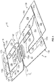
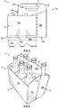
- Fig. 1 is a plan view of an exterior side 1 of a blank 3 used to form a package 4 ( Fig. 6 ) including a basket-style carrier 5 holding a plurality of containers C, in accordance with a first exemplary embodiment of the present disclosure.
- the carrier 5 is sized to contain six containers C, three containers being contained in a front portion of the carrier and three containers being contained in a back portion of the carrier.
- the carrier 5 can be sized and shaped to hold more or fewer than six containers C without departing from the disclosure.
- the carrier 5 includes a reinforced handle 7 ( Figs. 5 and 6 ), which can include a handle panel 14 and a handle reinforcement panel 16 among other features as described in more detail below.
- the carrier 5 is the erected carrier 5 of Fig. 6 that receives the containers C. As shown in Fig. 5 , the carrier 5 can be in a collapsed configuration, which can be referred to as the collapsed carrier 5a in one embodiment.
- the carrier blank 3 has a longitudinal axis L1 and a lateral or transverse axis L2 and has a front portion 9, a back portion 11, a bottom panel 12b foldably connected to the back portion, and a bottom attachment flap 12a foldably connected to the front portion.
- the front portion 9 and back portion 11 are for being folded about a lateral centerline CL ( Figs. 1 and 4 ) when the carrier blank 3 is formed into the carrier ( Figs. 5 and 6 ).
- the carrier blank 3 is formed into the collapsed carrier 5a by folding the carrier blank 3 about the centerline CL so that the front portion 9 and the back portion 11 are generally overlapped (e.g., Fig. 5 ).
- the blank 3 can be formed into a construct 6 (e.g., a folded construct or a balanced construct), which can be a folded blank or a partially formed carrier (e.g., as shown in Fig. 4 ) and/or the collapsed carrier 5a (e.g., as shown in Fig. 5 ).
- the construct 6 Fig. 4 and/or Fig. 5
- the construct 6 can be evenly stacked with other constructs 6 (e.g., for storage, shipping, etc.) prior to fully forming the erected carrier 5 (e.g., when preparing to receive the containers C).
- the front portion 9, comprises a front panel 15a foldably connected to a first side panel 17a and a second side panel 19a.
- a front central flap 27a is foldably connected to the first side panel 17a at a longitudinal fold line 29a.
- Longitudinal fold lines 31a, 33a foldably connect the respective first and second side panel 17a, 19a to the front panel 15a.
- a lateral fold line 35a connects the bottom panel attachment flap 12a to the front panel 15a.
- a bevel panel 36a can be formed in the bottom panel attachment flap 12a and can extend between the lateral fold line 35a and a lateral fold line 37a.
- the features of the back portion 11 of the blank 3 include a back panel 15b, a first side panel 17b, a second side panel 19b, and a back central flap 27b that are generally a mirror-image of the corresponding panel or flap of the front portion 9.
- the back central flap 27b and the front central flap 27a are foldably connected at a narrowed portion at the centerline CL.
- the central flaps 27a, 27b could be foldably connected along a lateral fold line (not shown).
- Corresponding components e.g., panels, flaps, fold lines, cuts, etc.
- corresponding reference numbers that differ by the "a” or "b” suffix, with the "a” components corresponding to the front portion 9 and the "b” components corresponding to the back portion 11 of the blank 3.
- the front portion 9 includes a front central panel 41 foldably connected to the second side panel 19a along a longitudinal fold line 43a.
- a first divider panel 47a e.g., a first front divider panel
- a second divider panel 51a e.g., a second front divider panel
- an attachment panel 55a e.g., a front attachment panel
- the first divider panel 47a and the attachment panel 55a are separable from the respective front central panel 41 and the second divider panel 51a along a cut line 63a extending from an end of the longitudinal fold line 49a to an end of the longitudinal fold line 61a.
- the back portion 11 includes a back central panel 69 foldably connected to the second side panel 19b along a longitudinal fold line 43b.
- the back central panel 69 can be a mirror image of the front central panel 41. As shown in Fig.
- a first divider panel 47b (e.g., a first back divider panel) is foldably connected to the back central panel 69 along a longitudinal fold line 49b
- a second divider panel 51b (e.g., a second back divider panel) is foldably connected to the back central panel 69 along a longitudinal fold line 53b
- an attachment panel 55b (e.g., a back attachment panel) is foldably connected to the divider panels 47b, 51b along respective longitudinal fold lines 59b, 61b.
- first divider panel 47b and the attachment panel 55b are separable from the respective back central panel 69 and second divider panel 51b along a cut line 63b extending from an end of the longitudinal fold line 49b to an end of the longitudinal fold line 61b.
- the front central panel 41 is foldably connected to the back central panel 69 along a line of weakening 128, which can include a fold line and one or more openings and/or cutouts.
- Any of the front portion 9, the back portion 11, the central flaps 27a, 27b, the central panels 41, 69, the divider panels 47a, 51a, 47b, 51b, and/or the attachment panels 55a, 55b could be omitted or could be alternatively shaped, arranged, positioned, and/or configured without departing from the present disclosure.
- the handle panel 14 and the handle reinforcement panel 16 are generally disposed between the front and back portions 9, 11.
- the handle panel 14 includes a front handle portion 21a and a back handle portion 21b foldably connected to the front handle portion 21a along a lateral fold line or other line of weakening 127.
- the front handle portion 21a is foldably connected to the front central panel 41 along the longitudinal fold line 43a
- the back handle portion 21b is foldably connected to the back central panel 69 along the longitudinal fold line 43b.
- the front handle portion 21a can include a front handle opening 22a and a front handle cushion flap 25a foldably connected to the front handle portion along a lateral fold line 26a adjacent the front handle opening 22a.
- the back handle portion 21b can include a back handle opening 22b and a back handle cushion flap 25b foldably connected to the back handle portion along a lateral fold line 26b adjacent the back handle opening 22b.
- the handle panel 14 could be omitted or could be otherwise shaped, arranged, and/or configured without departing from the disclosure.
- the handle reinforcement panel 16 can include a front handle reinforcement portion 97a and a back handle reinforcement portion 97b foldably connected to the front handle reinforcement portion 97a along a lateral fold line or other line of weakening 115.
- the front handle reinforcement portion 97a and the back handle reinforcement portion 97b are foldably connected to the respective front handle portion 21a and back handle portion 21b along a longitudinal fold line 131.
- the front handle reinforcement portion 97a includes an elongate handle opening 99a
- the back handle reinforcement portion 97b includes an elongate handle opening 99b.
- the line of weakening 128 and the lateral fold lines 115, 127 are generally aligned with the lateral centerline CL of the blank 3.
- the front handle portion 21a is adjacent the front panel 15a and the second side panel 19a, and the front handle reinforcement portion 97a is adjacent the front panel 15a, the first side panel 17a, and the front central flap 27a.
- the front handle portion 21a and the front handle reinforcement portion 97a are separable from the front panel 15a, the second side panel 19a, the first side panel 17a, and the front central flap 27a by a tear line or cut 23a.
- the back handle portion 21b and the back handle reinforcement portion 97b are separable from the back panel 15b, the second side panel 19b, the first side panel 17b, and the back central flap 27b by a tear line or cut 23b.
- the central panels 41, 69 further can reinforce the handle and can include handle openings 133a, 133b. Any of the handle portions, the handle reinforcement portions, and/or the handle reinforcement flap could be omitted or could be otherwise shaped, arranged, positioned, and/or configured without departing from the disclosure.
- the blank 3 can include balancing features for helping to balance the construct 6 so that the construct 6 can be stacked with other constructs 6 in a balanced stack (not shown) with even spacing between layers of the stack.
- the blank 3 can include balance flaps 135a, 136a foldably connected to the respective side panels 17a, 19a along respective lateral fold lines 137a and balance flaps 135b, 136b foldably connected to the respective side panels 17b, 19b along respective lateral fold lines 137b.
- the balance flaps 135a, 136a, 135b, 136b can cooperate with the central flaps 27a, 27b, the central panels 41, 69, and the side panels 17a, 19a, 17b, 19b so that each of the balance regions or corners 138 of the construct 6 have three layers of material to match the three layers of material in a central handle region 142 of the construct 6 (e.g., the overlapped portions of the handle panel 14, the handle reinforcement panel 16, the central panels 41, 69, and/or the central flaps 27a, 27b).
- Any of the balance features, including any of the balance flaps 135a, 136a, 135b, 136b could be omitted or could be otherwise shaped, arranged, positioned, and/or configured without departing from the disclosure.
- the carrier 5 formed from the blank 3 can be a pinhole-style basket carrier for being received in a crate with pins or posts (not shown).
- the pins of the crate can be received in the carrier between the containers therein to help locate and reduce movement of the carrier and containers in the crate.
- the blank 3 can include features for accommodating and receiving the pins. Such features can include in one embodiment apertures 139 in the bottom panel 12b and cutouts formed in the central panels 41, 69 and along the handle portions 21a, 21b and the handle reinforcement portions 97a, 97b.
- the carrier could be another style of carrier where the pinhole features are omitted.
- any of the panels, flaps, fold lines, cuts, or other features could be omitted or could be otherwise shaped, arranged, positioned, and/or configured in the blank 3 without departing from the disclosure.
- the blank 3 could be sized and/or shaped to accommodate more or fewer than six containers C without departing from this disclosure.
- the construct 6 can be formed from the blank 3 by positioning the panels 15a, 15b, 17a, 17b, 19a, 19b, the central flaps 27a, 27b, the central panels 41, 69, the divider panels 47a, 51a, 47b, 51b, the attachment panels 55a, 55b, and the balance flaps 135a, 136a, 135b, 136b relative to each other to form the front portion 9 and the back portion 11.
- the construct 6 further can be folded along the centerline CL and glued to form the collapsed carrier 5a ( Fig. 5 ).
- the blank 3 can be positioned with its interior surface 140 facing upwardly ( Fig. 2 ), and, as shown in Fig. 2 , the balance flaps 135a, 136a, 135b, 136b can be folded along the respective lateral fold lines 137a, 137b to overlap the interior surface 140 of the respective side panels 17a, 19a, 17b, 19b.
- the balance flaps 135a, 136a, 135b, 136b can be glued in face-to-face contact with the respective side panels 17a, 19a, 17b, 19b.
- the balance flaps 135a, 136a, 135b, 136b can cooperate with the respective side panels 17a, 19a, 17b, 19b to form four outer regions of the partially-formed construct with two layers of material.
- the handle reinforcement panel 16 e.g., the internal handle panel
- the handle panel 14 and the handle reinforcement panel 16 can be glued together in face-to-face contact.
- the handle openings 99a, 99b of the handle reinforcement panel 16 can be aligned with the respective handle openings 22a, 22b and the respective handle cushion flaps 25a, 25b of the handle panel 14.
- the handle reinforcement panel 16 overlapping the handle panel 14 can form a handle region of the partially-formed construct with two layers of material.
- the central panels 41, 69 can be folded along the longitudinal fold lines 43a, 43b so that the central panels 41, 69 overlap the respective side panels 19a, 19b and balance flaps 136a, 136b and so that the divider panels 47a, 51a, 47b, 51b and the attachment panels 55a, 55b overlap the respective front panel 15a and back panel 15b.
- the portions of the central panels 41, 69 overlapping the handle reinforcement panel 16 can be glued in face-to-face contact with the handle reinforcement panel 16 so that the handle openings 133a, 133b are aligned with the respective handle openings 99a, 99b of the handle reinforcement panel 16 and the respective handle openings 22a, 22b and the respective handle cushion flaps 25a, 25b of the handle panel 14.
- the line of weakening 128 of the central panels 41, 69, the lateral fold line 127 of the handle panel 14, and the line of weakening 115 of the handle reinforcement panel 16 can be aligned and in an overlapping relationship along the centerline CL.
- the attachment panels 55a, 55b can be glued in face-to-face contact with the respective front panel 15a and back panel 15b.
- the divider panels 47a, 51a, 47b, 51b remain unsecured to the front panel 15a and back panel 15b so that they may pivot with respect to the attachment panels 55a, 55b and the central panels 41, 69 when the carrier is formed.
- the central panels 41, 69 can remain unsecured to the side panels 19a, 19b so that they may pivot with respect to the side panels 19a, 19b.
- the partially-formed construct can have three layers of material at the central handle region 142 of the partially-formed construct and where the central panels 41, 69 overlap the respective balance flaps 136a, 136b at the respective corners 138 of the partially-formed construct.
- the partially-formed construct in Fig. 3 can have two layers of material where the central panels 41, 69 overlap the side panels 19a, 19b between the balance flaps 136a, 136b and the central handle region 142 and where the divider panels 47a, 51a, 47b, 51b and attachment panels 55a, 55b overlap the respective front panel 15a and back panel 15b, as well as where the balance flaps 135a, 135b overlap the side panels 17a, 17b.
- the central panels 41, 69 only partially overlap the respective handle reinforcement portions 97a, 97b of the handle reinforcement panel 16 so that the portion of the central handle region 142 that does not include the central panels 41, 69 has two layers of material (e.g., the portions of the handle panel 14 and the handle reinforcement panel 16 that are not overlapped by the central panels 41, 69).
- the first side panels 17a, 17b can be folded about respective fold lines 31a, 31b so that the first side panels 17a, 17b overlap the respective front panel 15a and back panel 15b with the respective balance flaps 135a, 135b therebetween and so that the central flaps 27a, 27b overlap the respective front panel 15a and back panel 15b, the respective divider panels 51a, 51b, the respective attachment flaps 55a, 55b, and the respective handle reinforcement portions 97a, 97b of the handle reinforcement panel 16.
- the central flaps 27a, 27b can be glued in face-to-face contact with to the portions of the respective handle reinforcement portions 97a, 97b of the handle reinforcement panel 16 that are not overlapped by the central panels 41, 69 so that the portion of the central handle region 142 of the construct 6 including the handle panel 14, the handle reinforcement panel 16, and the central flaps 27a, 27b has three layers of material.
- the corners 138 including the respective side panel 17a, 17b, the respective balance flaps 136a, 136b, and the respective front panel 15a and back panel 15b have three layers of material.
- the construct 6 ( Fig. 4 ) could be otherwise formed without departing from the disclosure.
- the balance flaps 135a, 135b, 136a, 136b can be folded into contact with the exterior surfaces of the respective side panels 17a, 17b, 19a, 19b.
- the construct 6 can have three layers of material distributed throughout the construct so that the construct is balanced for even stacking. While portions of the construct 6 can have one or two layers of material, the distributed three-layer portions of the construct are configured so that one or more portions (e.g., one or more corners 138) are not thinner than other portions of the construct, which can lead to a stack of constructs (not shown) that tilts or that is unstable. Rather, the distributed three-layer portions of the construct 6 allow the constructs to be stacked evenly so that each construct supports the constructs above it at at least the three-layer corners 138 and the three-layer central handle region 142.
- portions of the construct 6 can have one or two layers of material
- the distributed three-layer portions of the construct are configured so that one or more portions (e.g., one or more corners 138) are not thinner than other portions of the construct, which can lead to a stack of constructs (not shown) that tilts or that is unstable. Rather, the distributed three-layer portions of the construct 6 allow the constructs to be stacked
- the construct 6 can be supplied flat and even in board layers, which can be helpful when feeding the constructs 6 in certain feeders (e.g., for further processing) (e.g., systems produced by Krones AG and/or Schubert Packaging Systems GmbH).
- Constructs that lack the balancing features of the present disclosure can have board layers that are very uneven, which can make it difficult or impossible to stack the construct in a level pile.
- variations in thickness of a construct with different numbers of layers of material at different portions of the construct can add up in a stack of the constructs so that the stack can have significantly different heights between areas associated with portions of the constructs with different numbers of layers of material. This can result in the stack leaning in one direction or another and/or to the constructs being situated in unpredictable positions and/or orientations in the stack. Such discrepancies can cause stability issues in storage of the construct stack and/or issues with retrieving the constructs from the stack in a hopper for processing on a machine for example.
- the corners 138 with the balance features of the present disclosure help the construct 6 to be more easily stacked in a level pile for feeding into machinery (not shown) that requires or benefits from such level stacks of constructs.
- the construct 6 could be otherwise shaped, arranged, positioned, and/or configured without departing from the disclosure.
- the balancing features could have any suitable number of layers for balancing the stacked constructs.
- the construct 6, in the form of the folded blank shown in Fig. 4 can be folded about the lateral centerline CL (i.e., the lateral fold lines 115, 127, and the line of weakening 128) so that the front portion 9 generally overlaps the back portion 11 to form the flattened or collapsed carrier 5a ( Fig. 5 ).
- Portions of the front central panel 41 and the front central flap 27a can be selectively glued to portions of the respective back central panel 69 and back central flap 27b to generally form a central wall 144 ( Figs. 5 and 6 ) between the front portion 9 and the back portion 11.
- the handle panel 14, the handle reinforcement panel 16, and the handle portion of the central panels 41, 69 combine to form the six-ply reinforced handle 7 with the front handle openings 22a, 99a, 133a being generally aligned with the back handle openings 22b, 99b, 133b.
- the bottom panel 12b can be folded along a fold line and attached to the bottom panel attachment flap 12a by glue so that the collapsed carrier 5a is in a flattened configuration as shown in Fig. 5 .
- the central wall 144, the reinforced handle 7, and/or the bottom of the carrier could be otherwise shaped, arranged, positioned, and/or configured without departing from the disclosure.
- the construct 6 in the form of the flattened carrier 5a of Fig. 5 can be balanced by the balancing features in the same manner as the construct 6 in the form of the folded blank of Fig. 4 .
- the central handle region 142 having three layers of material in Fig. 4 can become the handle region 142' with six layers of material when the construct 6 (e.g., the folded blank) of Fig. 4 is folded to form the construct 6 (e.g., the flattened carrier 5a) of Fig. 5 .
- the corners 138 of the back portion 11 are overlapped by the corners 138 of the front portion 9 to form the corners 138' in the flattened carrier 5a of Fig.
- the flattened carrier 5a can be balanced for stacking in a similar manner as the construct 6 of Fig. 4 , wherein the six layers of material at the corners 138' and the handle region 142' are distributed in the construct 6 in the form of the flattened carrier 5a in Fig. 5 .
- the construct 6 can be fed into a packaging system by a feeder (not shown) and further formed into the erected carrier 5.
- a feeder not shown
- the first side panels 17a, 17b and second side panels 19a, 19b can be positioned to be in a generally spaced-apart, parallel planar relationship
- the front panel 15a and back panel 15b can be positioned to be in a generally spaced-apart, parallel planar relationship with the central wall 144 dividing the interior 146 of the carrier 5 into the front portion 9 and the back portion 11.
- the back portion 11 of the carrier is divided into three container-receiving spaces ( Fig. 6 ) by the divider flaps 47b, 51b.
- the separating of the front and back panels 15a, 15b further pulls the bottom panel 12b flat across the bottom of the carrier 5.
- Two hooks 13a, 13b ( Fig. 1 ) disposed at the bottoms of the respective central flaps 27a, 27b can engage a notch 28 ( Fig. 1 ) in the bottom panel 12b for supporting the bottom panel.
- the divider panels 47a, 51a, 47b, 51b can extend at least partially from the respective central panels 41, 69 to the respective front panel 15a and back panel 15b.
- the attachment panel 55a folds along longitudinal fold lines 59a, 61a with respect to the divider panels 47a, 51a so that the attachment panel 55a separates from the divider panel 51a along the cut line 63a.
- the attachment panel 55b can similarly separate from the divider panel 51b as the back panel 15b is positioned opposite to the back central panel 69.
- the carrier could be alternatively erected, formed, and/or arranged without departing from the present disclosure.
- containers C such as bottles
- the carrier 5 can be placed into the container-receiving spaces of the carrier 5 to form the package 4 ( Fig. 6 ).
- the bottoms of the containers are supported by the bottom panel 12b, and the divider panels 47a, 51a, 47b, 51b generally can extend between the wider lower portions of the containers to help prevent the containers from contacting respectively adjacent containers.
- the exemplary carrier embodiment discussed above accommodates six containers arranged in two rows, but the present disclosure is not limited to these numbers.
- additional containers may be accommodated by increasing the size of the blank 3 (e.g., in the lateral direction L2 in Fig. 1 ) and forming additional container-receiving spaces therein.
- the carrier 5 could have fewer than six container-receiving spaces.
- Fig. 7 is a plan view of a blank 203 for forming a collapsed or flattened carrier 205a ( Fig. 10 ), which can be further formed into an erected carrier (not shown) of a second embodiment of the disclosure.
- the second embodiment is generally similar to the first embodiment, except for variations noted and variations that will be apparent to one of ordinary skill in the art. Accordingly, similar or identical features of the embodiments have been given like or similar reference numbers. As shown in Fig.
- the blank 203 has a different handle panel 214 and handle reinforcement panel 216 than the blank 3, has different dividers 247a, 251a, 247b, 251b than the blank 3, and has second central panels 241, 269 that lack the handle features and divider panels of the central panels 41, 69 of the blank 3.
- the central panels 241, 269 can resemble the central flaps 27a, 27b so that the central flaps 27a, 27b can be referred to as first central flaps and the central panels 241, 269 can be referred to as second central flaps.
- the second central flaps 241, 269 are foldably connected at a line of weakening 328. Also, as shown in Fig.
- the bottom panel 212b and the bottom attachment flap 212a are foldably connected to the respective back panel 215b and front panel 215a along respective fold lines 35b, 35a and the bevel panels of the blank 3 are omitted.
- the balance features are differently configured in the blank 203.
- the balance flaps 335a, 336a, 335b, 336b are foldably connected to the respective central flaps 27a, 241, 27b, 269 along longitudinal fold lines 337a, 337b.
- the bottom panel 12b can include pinhole features 339 for receiving respective pins when the carrier is received in a crate. As shown in Fig.
- the pinhole features 339 each can include an aperture 339a and a plurality of flaps 339b that can fold upwardly into the erected carrier (not shown) as the pins are inserted into the apertures 339a.
- the carrier could be a different style of carrier wherein the pinhole features 339 are omitted.
- the divider panels 247a, 251a are foldably connected to the front panel 215a along respective longitudinal fold lines 259a, 261a, and the divider panels 247b, 251b are foldably connected to the back panel 215b along respective longitudinal fold lines 259b, 261b.
- the divider panel 247a is also foldably connected to the first handle portion 221a along a longitudinal fold line 249a
- the divider panel 251a is foldably connected to the first handle reinforcement portion 297a along a longitudinal fold line 253a
- the divider panel 247b is foldably connected to the second handle portion 221b along a longitudinal fold line 249b
- the divider panel 251b is foldably connected to the second handle reinforcing portion 297b along a longitudinal fold line 253b.
- a lateral fold line can extend in each of the divider panels 247a, 251a, 247b, 251b.
- the blank 203 could be otherwise shaped, arranged, positioned, and/or configured without departing from the disclosure.
- the blank 203 can be folded and selectively glued to form the construct 206 ( Figs. 9 and 10 ) as shown in Figs. 8-10 .
- the handle reinforcement panel 216 can be folded along fold lines 331 into face-to-face contact with the interior surface of the handle panel 214 so that the handle openings 99a, 99b are aligned with the respective handle flaps 25a, 25b and the respective handle openings 22a, 22b.
- the handle reinforcement panel 216 can be glued to the handle panel 214 and the divider panels 247a, 247b, 251a, 251b can remain unglued to other flaps or panels.
- the balance flaps 335a, 335b, 336a, 336b can be folded along the respective longitudinal fold lines 337a, 337b and glued to the interior surfaces of the respective central flaps 27a, 27b, 241, 269.
- the construct 206 in the form of the folded blank as shown in Fig. 9 can be further formed by folding the side panels 17a, 17b along fold lines 31a, 31b so that the side panels 17a, 17b and the central flaps 27a, 27b are in face-to-face contact with the respective front panel 15a and back panel 15b.
- portions of the central flaps 27a, 27b can overlap the handle reinforcement panel 216, which overlaps the handle panel 214, so that portions of the central handle region 342 have three layers of material.
- the central flaps 27a, 27b can be glued to the handle panel 214 via an opening extending in the handle reinforcement flap 216.
- the central flaps 27a, 27b can be glued to portions of the handle reinforcement flap 216 (e.g., adjacent to the opening in the handle reinforcement flap or in the case that the opening is omitted in the handle reinforcement flap 216).
- the central flaps 241, 269 can be folded along the respective fold lines 43a, 43b and into face-to-face contact with the side panels 19a, 19b.
- the central flaps 241, 269 can be glued to the interior surface of the handle panel 214 adjacent the handle reinforcement panel 216 and the overlapping portions of the central flaps 241, 269 and the side panels 19a, 19b can remain unglued.
- the construct 206 could be alternatively formed without departing from the present disclosure.
- one region 338 can include the overlapping central flap 27a and front panel 215a with the balance flap 335a therebetween, another region 338 can include the overlapping central flap 27b and back panel 215b with the balance flap 335b therebetween, another region 338 can include the overlapping central panel 241 and side panel 19a with the balance flap 336a therebetween, and another region 338 can include the overlapping central panel 269 and side panel 19b with the balance flap 336b therebetween.
- the balance flaps 335a, 336a, 335b, 336b can help form distributed three-layer regions in the construct 206 along with the three-layer portions of the central handle region 342 so that the construct 206 can be stacked with other constructs 206 in even layers more easily.
- the construct 206 can be further folded and glued to further form the carrier 205a (e.g., the construct 206 in the form of the collapsed carrier 205a).
- the construct 206 can be folded about the lateral centerline CL (i.e., the lateral fold lines 315, 127, and the line of weakening 328) so that the front portion 209 generally overlaps the back portion 211 ( Fig. 10 ).
- Portions of the front central flaps 241, 27a can be selectively glued to portions of the respective back central flaps 269, 27b to generally form a central wall (not shown) between the front portion 209 and the back portion 211.
- the handle panel 214 and the handle reinforcement panel 216 can combine to form the four-ply reinforced handle 207 ( Fig. 10 ) with the front handle openings 22a, 99a being generally aligned with the back handle openings 22b, 99b.
- the bottom panel 212b can be folded along a fold line and attached to the bottom panel attachment flap 212a by glue so that the folded construct 206 forms the flattened or collapsed carrier 205a ( Fig. 10 ).
- the construct 206 in the form of the collapsed carrier 205a can have a handle region 342' with portions that have six layers of material (e.g., where the central flaps 27a, 27b, the handle portions 221a, 221b, and the handle reinforcement portions 297a, 297b overlap in the handle 207) and balance regions 338' with six layers of material (e.g., where the central flaps 27a, 27b, the balance flaps 335a, 335b, the front panel 215a, and the back panel 215b overlap and where the central flaps 241, 269, the balance flaps 336a, 336b, and the side panels 19a, 19b overlap) so that there are regions of six layers of material distributed throughout the construct 206 in the form of the collapsed carrier 205a.
- the central wall, the reinforced handle, the balance regions, and/or the bottom of the carrier could be otherwise shaped, arranged, positioned, and/or configured without departing from the disclosure.
- the carrier can be further formed similarly to the carrier of the first embodiment.
- the carrier 205a could be alternatively erected, formed, and/or arranged without departing from the present disclosure.
- Fig. 11 is a plan view of a blank 403 for forming a carrier (not shown) of a third embodiment of the disclosure.
- the third embodiment is generally similar to the prior embodiments, except for variations noted and variations that will be apparent to one of ordinary skill in the art. Accordingly, similar or identical features of the embodiments have been given like or similar reference numbers.
- the blank 403 is similar to the blank 3 of Fig. 1 except that the pinhole features 139 included in the bottom panel 12b of the blank 3 are omitted in the bottom panel 412b of the blank 403.
- the cutouts included in handle portions 21a, 21b of the handle panel 14, the handle reinforcement portions 97a, 97b of the handle reinforcement panel 16, and the central panels 41, 69 of the blank 3 for accommodating the pins in the carrier 5 of the first embodiment are omitted in handle portions 421a, 421b of the handle panel 414, the handle reinforcement portions 497a, 497b of the handle reinforcement panel 416, and the central panels 441, 469 of the blank 403 of Fig. 11 .
- the blank 403 could be otherwise shaped, arranged, positioned, and/or configured without departing from the disclosure.
- Fig. 12 is a plan view of a blank 603 for forming a carrier (not shown) of a fourth embodiment of the disclosure.
- the fourth embodiment is generally similar to the prior embodiments, except for variations noted and variations that will be apparent to one of ordinary skill in the art. Accordingly, similar or identical features of the embodiments have been given like or similar reference numbers.
- the blank 603 is similar to the blank 203 of Fig. 7 except that the pinhole features 339 in the bottom panel 212b for accommodating the pins in the carrier 205 of the second embodiment are omitted in the bottom panel 612b of the blank 603 of Fig. 12 .
- the blank 603 could be otherwise shaped, arranged, positioned, and/or configured without departing from the disclosure.
- any of the features of the various embodiments of the disclosure can be combined with, replaced by, or otherwise configured with other features of other embodiments of the disclosure without departing from the scope of this disclosure.
- the panels, flaps, and other features shown and described in conjunction with the blanks 3, 203 and the carriers are included by way of example.
- the balance flaps 135a, 135b, 136a, 136b, 335a, 335b, 336a, 336b and/or other features of the disclosure can alternatively be associated with any basket-style carrier or other type of carton having any divider or panel configuration.
- the blank may be constructed from paperboard having a caliper so that it is heavier and more rigid than ordinary paper.
- the blank can also be constructed of other materials, such as cardboard, or any other material having properties suitable for enabling the carrier or carton to function at least generally as described above.
- the blank can be coated with, for example, a clay coating.
- the clay coating may then be printed over with product, advertising, and other information or images.
- the blanks may then be coated with a varnish to protect information printed on the blanks.
- the blanks may also be coated with, for example, a moisture barrier layer, on either or both sides of the blanks.
- the blanks can also be laminated to or coated with one or more sheet-like materials at selected panels or panel sections.
- a tear line can include: a slit that extends partially into the material along the desired line of weakness, and/or a series of spaced apart slits that extend partially into and/or completely through the material along the desired line of weakness, or various combinations of these features.
- one type tear line is in the form of a series of spaced apart slits that extend completely through the material, with adjacent slits being spaced apart slightly so that a nick (e.g., a small somewhat bridging-like piece of the material) is defined between the adjacent slits for typically temporarily connecting the material across the tear line. The nicks are broken during tearing along the tear line.
- the nicks typically are a relatively small percentage of the tear line, and alternatively the nicks can be omitted from or torn in a tear line such that the tear line is a continuous cut line. That is, it is within the scope of the present disclosure for each of the tear lines to be replaced with a continuous slit, or the like.
- a cut line can be a continuous slit or could be wider than a slit without departing from the present disclosure.
- a fold line can be any substantially linear, although not necessarily straight, form of weakening that facilitates folding therealong. More specifically, but not for the purpose of narrowing the scope of the present disclosure, fold lines include: a score line, such as lines formed with a blunt scoring knife, or the like, which creates a crushed or depressed portion in the material along the desired line of weakness; a cut that extends partially into a material along the desired line of weakness, and/or a series of cuts that extend partially into and/or completely through the material along the desired line of weakness; and various combinations of these features. In situations where cutting is used to create a fold line, typically the cutting will not be overly extensive in a manner that might cause a reasonable user to incorrectly consider the fold line to be a tear line.
- the above embodiments may be described as having one or more panels adhered together by glue during erection of the carrier embodiments.
- glue is intended to encompass all manner of adhesives commonly used to secure carrier panels in place.
Landscapes
- Engineering & Computer Science (AREA)
- Mechanical Engineering (AREA)
- Cartons (AREA)
- Packages (AREA)
Applications Claiming Priority (1)
| Application Number | Priority Date | Filing Date | Title |
|---|---|---|---|
| US201862641642P | 2018-03-12 | 2018-03-12 |
Publications (2)
| Publication Number | Publication Date |
|---|---|
| EP3539898A2 true EP3539898A2 (de) | 2019-09-18 |
| EP3539898A3 EP3539898A3 (de) | 2019-11-13 |
Family
ID=65766829
Family Applications (1)
| Application Number | Title | Priority Date | Filing Date |
|---|---|---|---|
| EP19161992.3A Withdrawn EP3539898A3 (de) | 2018-03-12 | 2019-03-11 | Träger für behälter |
Country Status (1)
| Country | Link |
|---|---|
| EP (1) | EP3539898A3 (de) |
Family Cites Families (3)
| Publication number | Priority date | Publication date | Assignee | Title |
|---|---|---|---|---|
| US2587808A (en) * | 1948-01-10 | 1952-03-04 | Morris Paper Mills | Bottle carrier |
| US20080296177A1 (en) * | 2003-12-16 | 2008-12-04 | E-Z Media, Inc. | Carrier and method |
| DE202011003191U1 (de) * | 2011-02-24 | 2011-06-01 | A&R Carton Bv | Flaschenträger |
-
2019
- 2019-03-11 EP EP19161992.3A patent/EP3539898A3/de not_active Withdrawn
Non-Patent Citations (1)
| Title |
|---|
| None |
Also Published As
| Publication number | Publication date |
|---|---|
| EP3539898A3 (de) | 2019-11-13 |
Similar Documents
| Publication | Publication Date | Title |
|---|---|---|
| CA2947296C (en) | Basket style carrier with divider flap | |
| EP2401210B1 (de) | Träger für behälter, zuscnhitt und verfahren zu seiner herstellung | |
| US20200189817A1 (en) | Carrier For Containers | |
| CA2785456C (en) | Carrier for containers | |
| AU2013290750B2 (en) | Carton with article protection feature | |
| US10518951B2 (en) | Carton for containers | |
| US20070295623A1 (en) | Carrier for Containers | |
| EP3221233B1 (de) | Karton mit verstärkungsmerkmalen | |
| CA2965526C (en) | Carton with reinforcement features | |
| WO2024238309A1 (en) | Carton for containers | |
| US12570450B2 (en) | Carrier for containers | |
| EP3539898A2 (de) | Träger für behälter | |
| US11987433B2 (en) | Article carrier and blank therefor | |
| EP4484317B1 (de) | Artikelträger und zuschnitt dafür | |
| US20160347522A1 (en) | Carton With Reinforcing Features | |
| US20230242315A1 (en) | Article carrier and blank therefor | |
| WO2026019804A1 (en) | Tray for holding articles |
Legal Events
| Date | Code | Title | Description |
|---|---|---|---|
| PUAI | Public reference made under article 153(3) epc to a published international application that has entered the european phase |
Free format text: ORIGINAL CODE: 0009012 |
|
| STAA | Information on the status of an ep patent application or granted ep patent |
Free format text: STATUS: THE APPLICATION HAS BEEN PUBLISHED |
|
| AK | Designated contracting states |
Kind code of ref document: A2 Designated state(s): AL AT BE BG CH CY CZ DE DK EE ES FI FR GB GR HR HU IE IS IT LI LT LU LV MC MK MT NL NO PL PT RO RS SE SI SK SM TR |
|
| AX | Request for extension of the european patent |
Extension state: BA ME |
|
| PUAL | Search report despatched |
Free format text: ORIGINAL CODE: 0009013 |
|
| AK | Designated contracting states |
Kind code of ref document: A3 Designated state(s): AL AT BE BG CH CY CZ DE DK EE ES FI FR GB GR HR HU IE IS IT LI LT LU LV MC MK MT NL NO PL PT RO RS SE SI SK SM TR |
|
| AX | Request for extension of the european patent |
Extension state: BA ME |
|
| RIC1 | Information provided on ipc code assigned before grant |
Ipc: B65D 71/58 20060101AFI20191009BHEP |
|
| STAA | Information on the status of an ep patent application or granted ep patent |
Free format text: STATUS: REQUEST FOR EXAMINATION WAS MADE |
|
| 17P | Request for examination filed |
Effective date: 20200513 |
|
| RBV | Designated contracting states (corrected) |
Designated state(s): AL AT BE BG CH CY CZ DE DK EE ES FI FR GB GR HR HU IE IS IT LI LT LU LV MC MK MT NL NO PL PT RO RS SE SI SK SM TR |
|
| STAA | Information on the status of an ep patent application or granted ep patent |
Free format text: STATUS: EXAMINATION IS IN PROGRESS |
|
| 17Q | First examination report despatched |
Effective date: 20201020 |
|
| STAA | Information on the status of an ep patent application or granted ep patent |
Free format text: STATUS: THE APPLICATION IS DEEMED TO BE WITHDRAWN |
|
| 18D | Application deemed to be withdrawn |
Effective date: 20221001 |