EP3539673A1 - Robot system and control method of robot - Google Patents
Robot system and control method of robot Download PDFInfo
- Publication number
- EP3539673A1 EP3539673A1 EP19156469.9A EP19156469A EP3539673A1 EP 3539673 A1 EP3539673 A1 EP 3539673A1 EP 19156469 A EP19156469 A EP 19156469A EP 3539673 A1 EP3539673 A1 EP 3539673A1
- Authority
- EP
- European Patent Office
- Prior art keywords
- application
- liquid
- distance
- robot
- thickness
- Prior art date
- Legal status (The legal status is an assumption and is not a legal conclusion. Google has not performed a legal analysis and makes no representation as to the accuracy of the status listed.)
- Granted
Links
Images


Classifications
-
- B—PERFORMING OPERATIONS; TRANSPORTING
- B25—HAND TOOLS; PORTABLE POWER-DRIVEN TOOLS; MANIPULATORS
- B25J—MANIPULATORS; CHAMBERS PROVIDED WITH MANIPULATION DEVICES
- B25J11/00—Manipulators not otherwise provided for
- B25J11/0075—Manipulators for painting or coating
-
- B—PERFORMING OPERATIONS; TRANSPORTING
- B05—SPRAYING OR ATOMISING IN GENERAL; APPLYING FLUENT MATERIALS TO SURFACES, IN GENERAL
- B05B—SPRAYING APPARATUS; ATOMISING APPARATUS; NOZZLES
- B05B12/00—Arrangements for controlling delivery; Arrangements for controlling the spray area
- B05B12/08—Arrangements for controlling delivery; Arrangements for controlling the spray area responsive to condition of liquid or other fluent material to be discharged, of ambient medium or of target ; responsive to condition of spray devices or of supply means, e.g. pipes, pumps or their drive means
- B05B12/084—Arrangements for controlling delivery; Arrangements for controlling the spray area responsive to condition of liquid or other fluent material to be discharged, of ambient medium or of target ; responsive to condition of spray devices or of supply means, e.g. pipes, pumps or their drive means responsive to condition of liquid or other fluent material already sprayed on the target, e.g. coating thickness, weight or pattern
-
- B—PERFORMING OPERATIONS; TRANSPORTING
- B05—SPRAYING OR ATOMISING IN GENERAL; APPLYING FLUENT MATERIALS TO SURFACES, IN GENERAL
- B05B—SPRAYING APPARATUS; ATOMISING APPARATUS; NOZZLES
- B05B12/00—Arrangements for controlling delivery; Arrangements for controlling the spray area
- B05B12/08—Arrangements for controlling delivery; Arrangements for controlling the spray area responsive to condition of liquid or other fluent material to be discharged, of ambient medium or of target ; responsive to condition of spray devices or of supply means, e.g. pipes, pumps or their drive means
- B05B12/12—Arrangements for controlling delivery; Arrangements for controlling the spray area responsive to condition of liquid or other fluent material to be discharged, of ambient medium or of target ; responsive to condition of spray devices or of supply means, e.g. pipes, pumps or their drive means responsive to conditions of ambient medium or target, e.g. humidity, temperature position or movement of the target relative to the spray apparatus
- B05B12/124—Arrangements for controlling delivery; Arrangements for controlling the spray area responsive to condition of liquid or other fluent material to be discharged, of ambient medium or of target ; responsive to condition of spray devices or of supply means, e.g. pipes, pumps or their drive means responsive to conditions of ambient medium or target, e.g. humidity, temperature position or movement of the target relative to the spray apparatus responsive to distance between spray apparatus and target
-
- B—PERFORMING OPERATIONS; TRANSPORTING
- B05—SPRAYING OR ATOMISING IN GENERAL; APPLYING FLUENT MATERIALS TO SURFACES, IN GENERAL
- B05B—SPRAYING APPARATUS; ATOMISING APPARATUS; NOZZLES
- B05B13/00—Machines or plants for applying liquids or other fluent materials to surfaces of objects or other work by spraying, not covered by groups B05B1/00 - B05B11/00
- B05B13/02—Means for supporting work; Arrangement or mounting of spray heads; Adaptation or arrangement of means for feeding work
- B05B13/04—Means for supporting work; Arrangement or mounting of spray heads; Adaptation or arrangement of means for feeding work the spray heads being moved during spraying operation
- B05B13/0431—Means for supporting work; Arrangement or mounting of spray heads; Adaptation or arrangement of means for feeding work the spray heads being moved during spraying operation with spray heads moved by robots or articulated arms, e.g. for applying liquid or other fluent material to three-dimensional [3D] surfaces
-
- B—PERFORMING OPERATIONS; TRANSPORTING
- B05—SPRAYING OR ATOMISING IN GENERAL; APPLYING FLUENT MATERIALS TO SURFACES, IN GENERAL
- B05C—APPARATUS FOR APPLYING FLUENT MATERIALS TO SURFACES, IN GENERAL
- B05C11/00—Component parts, details or accessories not specifically provided for in groups B05C1/00 - B05C9/00
- B05C11/10—Storage, supply or control of liquid or other fluent material; Recovery of excess liquid or other fluent material
- B05C11/1002—Means for controlling supply, i.e. flow or pressure, of liquid or other fluent material to the applying apparatus, e.g. valves
- B05C11/1005—Means for controlling supply, i.e. flow or pressure, of liquid or other fluent material to the applying apparatus, e.g. valves responsive to condition of liquid or other fluent material already applied to the surface, e.g. coating thickness, weight or pattern
-
- B—PERFORMING OPERATIONS; TRANSPORTING
- B05—SPRAYING OR ATOMISING IN GENERAL; APPLYING FLUENT MATERIALS TO SURFACES, IN GENERAL
- B05C—APPARATUS FOR APPLYING FLUENT MATERIALS TO SURFACES, IN GENERAL
- B05C11/00—Component parts, details or accessories not specifically provided for in groups B05C1/00 - B05C9/00
- B05C11/10—Storage, supply or control of liquid or other fluent material; Recovery of excess liquid or other fluent material
- B05C11/1002—Means for controlling supply, i.e. flow or pressure, of liquid or other fluent material to the applying apparatus, e.g. valves
- B05C11/1015—Means for controlling supply, i.e. flow or pressure, of liquid or other fluent material to the applying apparatus, e.g. valves responsive to a conditions of ambient medium or target, e.g. humidity, temperature ; responsive to position or movement of the coating head relative to the target
- B05C11/1018—Means for controlling supply, i.e. flow or pressure, of liquid or other fluent material to the applying apparatus, e.g. valves responsive to a conditions of ambient medium or target, e.g. humidity, temperature ; responsive to position or movement of the coating head relative to the target responsive to distance of target
-
- B—PERFORMING OPERATIONS; TRANSPORTING
- B05—SPRAYING OR ATOMISING IN GENERAL; APPLYING FLUENT MATERIALS TO SURFACES, IN GENERAL
- B05C—APPARATUS FOR APPLYING FLUENT MATERIALS TO SURFACES, IN GENERAL
- B05C5/00—Apparatus in which liquid or other fluent material is projected, poured or allowed to flow on to the surface of the work
- B05C5/02—Apparatus in which liquid or other fluent material is projected, poured or allowed to flow on to the surface of the work the liquid or other fluent material being discharged through an outlet orifice by pressure, e.g. from an outlet device in contact or almost in contact, with the work
- B05C5/0208—Apparatus in which liquid or other fluent material is projected, poured or allowed to flow on to the surface of the work the liquid or other fluent material being discharged through an outlet orifice by pressure, e.g. from an outlet device in contact or almost in contact, with the work for applying liquid or other fluent material to separate articles
-
- B—PERFORMING OPERATIONS; TRANSPORTING
- B25—HAND TOOLS; PORTABLE POWER-DRIVEN TOOLS; MANIPULATORS
- B25J—MANIPULATORS; CHAMBERS PROVIDED WITH MANIPULATION DEVICES
- B25J13/00—Controls for manipulators
-
- B—PERFORMING OPERATIONS; TRANSPORTING
- B25—HAND TOOLS; PORTABLE POWER-DRIVEN TOOLS; MANIPULATORS
- B25J—MANIPULATORS; CHAMBERS PROVIDED WITH MANIPULATION DEVICES
- B25J13/00—Controls for manipulators
- B25J13/08—Controls for manipulators by means of sensing devices, e.g. viewing or touching devices
-
- B—PERFORMING OPERATIONS; TRANSPORTING
- B25—HAND TOOLS; PORTABLE POWER-DRIVEN TOOLS; MANIPULATORS
- B25J—MANIPULATORS; CHAMBERS PROVIDED WITH MANIPULATION DEVICES
- B25J13/00—Controls for manipulators
- B25J13/08—Controls for manipulators by means of sensing devices, e.g. viewing or touching devices
- B25J13/087—Controls for manipulators by means of sensing devices, e.g. viewing or touching devices for sensing other physical parameters, e.g. electrical or chemical properties
-
- B—PERFORMING OPERATIONS; TRANSPORTING
- B25—HAND TOOLS; PORTABLE POWER-DRIVEN TOOLS; MANIPULATORS
- B25J—MANIPULATORS; CHAMBERS PROVIDED WITH MANIPULATION DEVICES
- B25J13/00—Controls for manipulators
- B25J13/08—Controls for manipulators by means of sensing devices, e.g. viewing or touching devices
- B25J13/088—Controls for manipulators by means of sensing devices, e.g. viewing or touching devices with position, velocity or acceleration sensors
- B25J13/089—Determining the position of the robot with reference to its environment
-
- B—PERFORMING OPERATIONS; TRANSPORTING
- B25—HAND TOOLS; PORTABLE POWER-DRIVEN TOOLS; MANIPULATORS
- B25J—MANIPULATORS; CHAMBERS PROVIDED WITH MANIPULATION DEVICES
- B25J19/00—Accessories fitted to manipulators, e.g. for monitoring, for viewing; Safety devices combined with or specially adapted for use in connection with manipulators
- B25J19/02—Sensing devices
-
- B—PERFORMING OPERATIONS; TRANSPORTING
- B25—HAND TOOLS; PORTABLE POWER-DRIVEN TOOLS; MANIPULATORS
- B25J—MANIPULATORS; CHAMBERS PROVIDED WITH MANIPULATION DEVICES
- B25J9/00—Program-controlled manipulators
- B25J9/16—Program controls
- B25J9/1694—Program controls characterised by use of sensors other than normal servo-feedback from position, speed or acceleration sensors, perception control, multi-sensor controlled systems, sensor fusion
Definitions
- the disclosure relates to a robot system and a control method of a robot.
- Patent Document 1 discloses a technique of attaching a die head to an actuator that moves up and down, measuring a distance between the die head and a surface of a substrate by a distance measuring sensor provided on the die head, and maintaining the distance between the die head and the surface of the substrate at a set distance. According to Patent Document 1, a uniform coating film is formed on the substrate in accordance with undulation of the substrate.
- Patent Document 2 discloses a technique of setting a position of a chemical solution nozzle relative to a base according to viscosity of a solution. According to Patent Document 2, a high-viscosity solution is applied to a surface of the base with a uniform film thickness.
- an application thickness of the liquid is affected by not only the undulation of the substrate but also ambient temperature, remaining amount of the liquid in a liquid application part, or pressure inside the liquid application part and so on.
- an application amount of the liquid cannot be controlled in real time in accordance with a change in the ambient temperature and so on, and the liquid cannot be applied with a uniform layer thickness.
- a subject of the disclosure is to provide a robot system and a control method of a robot capable of applying a liquid with a uniform layer thickness even if there is a change in conditions such as ambient temperature and so on.
- a robot system of the disclosure includes:
- the liquid is applied by the liquid application part provided on the robot, and the application thickness of the liquid is measured by the application thickness measurement part.
- the distance measurement part measures the first distance from the distance measurement part to the application object.
- the control part controls the robot based on the first distance so that the second distance from the liquid application part to the application object becomes constant.
- the supply amount adjustment part adjusts the supply amount of the liquid to the application object according to the application thickness measured by the application thickness measurement part.
- the distance measurement part, the liquid application part and the application thickness measurement part are arranged in this order in the application direction of the liquid.
- the supply amount of the liquid is linearly controlled in real time according to the application thickness of the liquid while the application thickness is measured using the distance measurement part and the application thickness measurement part, even if there is a change in the conditions such as ambient temperature and so on, the liquid can be applied with a uniform layer thickness.
- the distance measurement part, the liquid application part and the application thickness measurement part are arranged in this order in the application direction of the liquid, it is possible to measure the application thickness by a time difference calculation.
- the control part controls the robot based on the first distance so that the second distance from the liquid application part to the application object becomes constant, and when the application thickness measurement part arrives at the point on the application object where the first distance is measured by the distance measurement part, the application thickness measurement part measures the application thickness of the liquid based on a distance from the application thickness measurement part to an applied surface and the first distance.
- the distance measurement part by the distance measurement part, the liquid application part and the application thickness measurement part arranged in the above order, it is possible to measure the application thickness and adjust the supply amount of the liquid by a time difference calculation.
- the liquid application part includes a syringe and a nozzle, wherein the nozzle includes a throttle element of a discharge port of the liquid, and the supply amount adjustment part adjusts the supply amount of the liquid to the application object by driving the throttle clement.
- the supply amount of the liquid is adjusted by driving the throttle element of the nozzle.
- the application thickness of the supplied liquid is measured as described above, and the distance between the liquid application part and the application object is linearly controlled in real time according to the application thickness. Accordingly, even if there is a change in the conditions such as ambient temperature and so on, the liquid can be applied with a uniform layer thickness.
- the liquid application part includes a syringe and a nozzle, wherein a discharge of the liquid is suppressed by creating negative pressure inside the syringe, and the discharge of the liquid is performed by creating atmospheric pressure or positive pressure inside the syringe, and the supply amount adjustment part adjusts the supply amount of the liquid to the application object by adjusting a distance between the nozzle and the application object.
- a discharge amount of the liquid varies depending on the distance between the nozzle and the application object.
- the application thickness of the discharged liquid is measured, and the distance between the liquid application part and the application object is linearly controlled in real time according to the application thickness. Accordingly, even if there is a change in the conditions such as ambient temperature and so on, the liquid can be applied with a uniform layer thickness.
- a control method of a robot of the disclosure includes following steps:
- the supply amount of the liquid is linearly controlled in real time according to the application thickness of the liquid while the application thickness is measured using a distance measurement part and the application thickness measurement part, even if there is a change in the conditions such as ambient temperature and so on, the liquid can be applied with a uniform layer thickness.
- the liquid can be applied with a uniform layer thickness.
- FIG. 1 is a top view showing a robot system 100 in an embodiment of the present disclosure.
- the robot system 100 in the present embodiment includes a robot 10, a dispenser head 20, a dispenser controller 30 as a control device of the robot 10. and a workpiece 40 as an application object.
- the robot 10 is, for example, an arm type six-axis articulated robot.
- the arm type six-axis articulated robot includes a power source such as a servomotor or the like, wherein the servomotor is driven by a control signal output from the dispenser controller 30 based on a robot control program and each joint axis is operated.
- the dispenser head 20 applies a liquid to the workpiece 40.
- a liquid such as a sealer material, water-based printing ink, engine oil, olive oil or the like, for example, may be used.
- FIG. 2 is a side view showing a configuration of the dispenser head 20.
- the dispenser head 20 includes a holder 21, a distance measuring sensor 22a, an application thickness measuring sensor 22b, a syringe 23, and a nozzle 24 as a liquid application part.
- the holder 21 holds the distance measuring sensor 22a, the application thickness measuring sensor 22b and the syringe 23.
- the distance measuring sensor 22a is a sensor for measuring a first distance from the distance measuring sensor 22a to the workpiece 40.
- a reflective sensor may be used.
- the application thickness measuring sensor 22b is a sensor for detecting an application thickness d of the liquid applied to the workpiece 40.
- a reflective sensor may be used.
- the syringe 23 is a container containing the liquid to be applied.
- the nozzle 24 is a tube attached to a tip of the syringe 23 and discharging the liquid.
- the distance measuring sensor 22a, the nozzle 24 and the application thickness measuring sensor 22b are arranged in this order in an application direction of the liquid as shown by an arrow F.
- the dispenser controller 30 is a control device controlling the robot 10 to keep a constant distance between the nozzle 24 and the workpiece 40 and to adjust an application amount of the liquid.
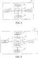
- FIG. 3 shows hardware configuration of the dispenser controller 30.
- the dispenser controller 30 includes an input device 31, a display device 32, a central arithmetic device 33, a memory device 34 and a communication interface (I/F) 35.
- the input device 31 is composed of a keyboard and so on.
- the display device 32 is composed of a display.
- the central arithmetic device 33 is composed of a central processing unit (CPU).
- the memory device 34 includes a nonvolatile memory device and a volatile memory device, wherein the nonvolatile memory device stores the robot control program and a sequence control program and so on.
- the volatile memory device is properly used as a work memory during execution of the central arithmetic device 33.
- the communication I/F 35 is, for example, an interface of a serial line such as RS232C or the like, and inputs an output value of the sensor 22 and communicates with the robot 10.
- the communication I/F 35 may also be an interface of other communication line.
- FIG. 4 is a functional block diagram of the dispenser controller 30 in the present embodiment.
- the dispenser controller 30 functions as an input processing part 71, a display processing part 72, an arithmetic part 73, a memory part 74, and a communication processing part 75.
- the processing part 71 processes an input from the input device 31.
- the display processing part 72 creates display data to be output to the display device 32.
- the arithmetic part 73 includes a control part 73a and a supply amount adjustment part 73b.
- the control part 73a controls the robot 10 based on the above first distance so that a second distance from the nozzle 24 to the workpiece 40 becomes constant.
- the supply amount adjustment part 73b adjusts a supply amount of the liquid to the workpiece 40 according to an application thickness measured by the application thickness measuring sensor 22b. Details of functions of the control part 73a and the supply amount adjustment part 73b are described later.
- the memory part 74 stores the robot control program and the sequence control program and so on.
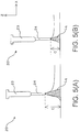
- FIG. 5(A) and FIG. 5(B) are diagrams for illustrating an adjustment method of an application amount of an application liquid Lq to the workpiece 40 in the present embodiment.
- the dispenser head 20 by creating negative pressure inside the syringe 23, it is suppressed that the application liquid Lq drops down due to gravity.
- the application liquid Lq is discharged.
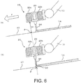
- FIG. 6 are diagrams for explaining a control method of the distance between the nozzle and the workpiece in the present embodiment.
- the control part 73a measures a first distance D1 between the nozzle 24 and the workpiece 40 at a point P on the workpiece 40 at a certain moment. Then, the dispenser head 20 is moved in the application direction of the liquid as shown by the arrow F, and when the nozzle 24 arrives at the point P, as shown in (B) of FIG. 6 , the control part 73a drives the dispenser head 20 based on the first distance D1 so that a second distance D2 between the nozzle 24 and the workpiece 40 becomes constant.
- the second distance D2 between the nozzle 24 and the workpiece 40 can be kept constant. Accordingly, even if undulation occurs in a surface of the workpiece 40, the distance between the nozzle 24 and the workpiece 40 is kept constant and the application thickness can be made constant.
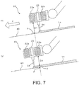
- FIG. 7 are diagrams for explaining the application thickness measurement method in the present embodiment.
- the control part 73a measures the first distance D1 between the nozzle 24 and the workpiece 40 at the point P on the workpiece 40 at a certain moment.
- the control part 73a keeps constant the second distance D2 between the nozzle 24 and the workpiece 40 as described above.
- the application thickness measuring sensor 22b measures the application thickness d by measuring a distance D3 from the application thickness measuring sensor 22b to an applied surface of the application liquid Lq, and subtracting the distance D3 from the above first distance D1.
- the application thickness of the liquid is measured by a time difference calculation using two sensors, namely, the distance measuring sensor 22a and the application thickness measuring sensor 22b.
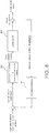
- FIG. 8 is a block diagram showing a control loop of control of the distance between the nozzle and the workpiece in the present embodiment.
- the control part 73a of the dispenser controller 30 measures the first distance D1 between the distance measuring sensor 22a and the workpiece 40 by the distance measuring sensor 22a.
- the control part 73a calculates the second distance D2 between the nozzle 24 and the workpiece 40.
- control part 73a delays a feedback of the second distance D2 by a time delay processing function 81.
- a delay time is set to, for example, a period of time from a moment when the first distance D1 is measured at the point P to when the nozzle 24 arrives at the point P.
- a target value is determined in advance. From this target value and the second distance D2 provided as delayed feedback, the control part 73a calculates a variable value of a height of the nozzle 24 relative to the target value. Next, the control part 73a inputs the variable value of the height of the nozzle 24 to a variable value-command conversion function 82.
- a variable value-command conversion function 82 if the variable value of the height of the nozzle 24 is greater than the target value, a command to move the dispenser head 20 in a Z-axis minus direction (downward direction) is output.
- a command to move the dispenser head 20 in a Z-axis plus direction (upward direction) is output.
- An operation command in the Z-axis direction that is output from the variable value-command conversion function 82 is input to a Z-axis control function 83.
- the Z-axis control function 83 moves the dispenser head 20 according to the input operation command.
- the distance between the nozzle 24 and the workpiece 40 is kept constant.
- FIG. 9 is a block diagram showing a control loop of Z-axis (vertical direction) control of the dispenser head 20 in the present embodiment.
- the control part 73a of the dispenser controller 30 measures the above first distance D1 by the distance measuring sensor 22a.
- control part 73a delays a feedback of the first distance D1 by a time delay processing function 90.
- a delay time is set to, for example, a period of time from a moment when the first distance D1 is measured at the point P to when the application thickness measuring sensor 22b arrives at the point P.
- the application thickness measuring sensor 22b measures the distance D3 from the application thickness measuring sensor 22b to the applied surface. Then, by subtracting the distance D3 from the first distance D1 provided as delayed feedback as described above, the application thickness d is calculated.
- the supply amount adjustment part 73b converts the application thickness d into an application liquid capacity by a height-capacity conversion function 91. As a result, since a current value of the application liquid capacity is known, the supply amount adjustment part 73b returns the current value as feedback.
- a target value of the application liquid capacity is determined in advance. From the target value of the application liquid capacity and the feedback of the current value of the application liquid capacity, the supply amount adjustment part 73b calculates a variable value relative to the target value of the application liquid capacity. Next, the supply amount adjustment part 73b inputs the variable value of the application liquid capacity to a variable value-command conversion function 92. In the variable value-command conversion function 92, if the variable value of the application liquid capacity is greater than the target value of the application liquid capacity, i.e., if the application amount is large, a command to move the dispenser head 20 in the Z-axis minus direction (downward direction) is output.
- variable value-command conversion function 92 if the variable value of the application liquid capacity is smaller than the target value of the application liquid capacity, i.e., if the application amount is small, a command to move the dispenser head 20 in the Z-axis plus direction (upward direction) is output.
- An operation command in the Z-axis direction that is output from the variable value-command conversion function 92 is input to a Z-axis control function 93.
- the Z-axis control function 93 moves the dispenser head 20 according to the input operation command.
- the application amount is controlled.
- the dispenser head 20 is linearly controlled to move in the Z-axis direction, so as to keep the constant distance between the nozzle 24 and the applied surface on the workpiece 40 where the application liquid Lq is applied.
- the application thickness of the application liquid Lq on the workpiece 40 can be kept constant.
- the application thickness d can be reliably measured accordingly.
- the application thickness of the application liquid Lq on the workpiece 40 can be kept constant.
- the cost can be reduced.
- a throttle element may be provided on the nozzle 24, so as to adjust the supply amount of the liquid by driving the throttle element.
Landscapes
- Engineering & Computer Science (AREA)
- Robotics (AREA)
- Mechanical Engineering (AREA)
- Human Computer Interaction (AREA)
- Coating Apparatus (AREA)
- Spray Control Apparatus (AREA)
- Manipulator (AREA)
- Application Of Or Painting With Fluid Materials (AREA)
Abstract
Description
- The disclosure relates to a robot system and a control method of a robot.
-
Patent Document 1 discloses a technique of attaching a die head to an actuator that moves up and down, measuring a distance between the die head and a surface of a substrate by a distance measuring sensor provided on the die head, and maintaining the distance between the die head and the surface of the substrate at a set distance. According toPatent Document 1, a uniform coating film is formed on the substrate in accordance with undulation of the substrate. - Patent Document 2 discloses a technique of setting a position of a chemical solution nozzle relative to a base according to viscosity of a solution. According to Patent Document 2, a high-viscosity solution is applied to a surface of the base with a uniform film thickness.
-
- [Patent Document 1] Japanese Laid-open No.
2004-298697 - [Patent Document 2] Japanese Laid-open No.
2010-042325 - However, if a robot is used to apply a liquid to a substrate or the like, an application thickness of the liquid is affected by not only the undulation of the substrate but also ambient temperature, remaining amount of the liquid in a liquid application part, or pressure inside the liquid application part and so on. In this regard, in the techniques described in
Patent Documents 1 and 2, an application amount of the liquid cannot be controlled in real time in accordance with a change in the ambient temperature and so on, and the liquid cannot be applied with a uniform layer thickness. - Therefore, a subject of the disclosure is to provide a robot system and a control method of a robot capable of applying a liquid with a uniform layer thickness even if there is a change in conditions such as ambient temperature and so on.
- To solve the above problems, a robot system of the disclosure includes:
- a robot;
- a liquid application part provided on the robot;
- an application thickness measurement part measuring an application thickness of a liquid applied by the liquid application part;
- a distance measurement part measuring a first distance from the distance measurement part to an application object;
- a control part controlling the robot based on the first distance so that a second distance from the liquid application part to the application object becomes constant; and
- a supply amount adjustment part adjusting a supply amount of the liquid to the application object according to the application thickness measured by the application thickness measurement part, wherein
- the distance measurement part, the liquid application part and the application thickness measurement part are arranged in this order in an application direction of the liquid.
- In the above robot system, the liquid is applied by the liquid application part provided on the robot, and the application thickness of the liquid is measured by the application thickness measurement part. The distance measurement part measures the first distance from the distance measurement part to the application object. The control part controls the robot based on the first distance so that the second distance from the liquid application part to the application object becomes constant. The supply amount adjustment part adjusts the supply amount of the liquid to the application object according to the application thickness measured by the application thickness measurement part.
- In the robot system as described above, the distance measurement part, the liquid application part and the application thickness measurement part are arranged in this order in the application direction of the liquid.
- Accordingly, according to the above robot system, since the supply amount of the liquid is linearly controlled in real time according to the application thickness of the liquid while the application thickness is measured using the distance measurement part and the application thickness measurement part, even if there is a change in the conditions such as ambient temperature and so on, the liquid can be applied with a uniform layer thickness.
- In addition, according to the above robot system, since the distance measurement part, the liquid application part and the application thickness measurement part are arranged in this order in the application direction of the liquid, it is possible to measure the application thickness by a time difference calculation.
- In the robot system of an embodiment, when the liquid application part arrives at a point on the application object where the first distance is measured by the distance measurement part, the control part controls the robot based on the first distance so that the second distance from the liquid application part to the application object becomes constant, and when the application thickness measurement part arrives at the point on the application object where the first distance is measured by the distance measurement part, the application thickness measurement part measures the application thickness of the liquid based on a distance from the application thickness measurement part to an applied surface and the first distance.
- In the robot system of the embodiment, by the distance measurement part, the liquid application part and the application thickness measurement part arranged in the above order, it is possible to measure the application thickness and adjust the supply amount of the liquid by a time difference calculation.
- In the robot system of an embodiment, the liquid application part includes a syringe and a nozzle, wherein the nozzle includes a throttle element of a discharge port of the liquid, and the supply amount adjustment part adjusts the supply amount of the liquid to the application object by driving the throttle clement.
- In the robot system of the embodiment, the supply amount of the liquid is adjusted by driving the throttle element of the nozzle. The application thickness of the supplied liquid is measured as described above, and the distance between the liquid application part and the application object is linearly controlled in real time according to the application thickness. Accordingly, even if there is a change in the conditions such as ambient temperature and so on, the liquid can be applied with a uniform layer thickness.
- In the robot system of an embodiment, the liquid application part includes a syringe and a nozzle, wherein a discharge of the liquid is suppressed by creating negative pressure inside the syringe, and the discharge of the liquid is performed by creating atmospheric pressure or positive pressure inside the syringe, and the supply amount adjustment part adjusts the supply amount of the liquid to the application object by adjusting a distance between the nozzle and the application object.
- In the robot system of the embodiment, in the case where the pressure inside the syringe is changed to positive pressure, a discharge amount of the liquid varies depending on the distance between the nozzle and the application object. The application thickness of the discharged liquid is measured, and the distance between the liquid application part and the application object is linearly controlled in real time according to the application thickness. Accordingly, even if there is a change in the conditions such as ambient temperature and so on, the liquid can be applied with a uniform layer thickness.
- To solve the above problems, a control method of a robot of the disclosure includes following steps:
- measuring an application thickness of a liquid applied by a liquid application part provided on the robot;
- measuring a first distance from a distance measurement part to an application object;
- controlling the robot based on the first distance so that a second distance from the liquid application part to the application object becomes constant; and
- adjusting a supply amount of the liquid to the application object according to the measured application thickness, wherein
- processing is performed in an order of the step of measuring the distance to the application object, the step of applying the liquid by the liquid application part and the step of measuring the application thickness.
- According to the control method of the disclosure, since the supply amount of the liquid is linearly controlled in real time according to the application thickness of the liquid while the application thickness is measured using a distance measurement part and the application thickness measurement part, even if there is a change in the conditions such as ambient temperature and so on, the liquid can be applied with a uniform layer thickness.
- In addition, according to the above control method, since the processing is performed in the order of the step of measuring the distance to the application object, the step of applying the liquid by the liquid application part and the step of measuring the application thickness, it is possible to measure the application thickness by a time difference calculation.
- As clear from the above, according to the robot system and the control method of a robot of the disclosure, even if there is a change in the conditions such as ambient temperature and so on, the liquid can be applied with a uniform layer thickness.
-
-
FIG. 1 is a top view showing a robot system in an embodiment. -
FIG. 2 is a side view showing a configuration of a dispenser head. -
FIG. 3 is a block diagram showing hardware configuration of a dispenser controller. -
FIG. 4 is a functional block diagram of the dispenser controller. -
FIG. 5(A) illustrates a discharge of an application liquid in the case where a workpiece and a nozzle are far from each other;FIG. 5(B) illustrates the discharge of the application liquid in the case where the workpiece and the nozzle are not as far from each other as they are inFIG. 5(A) . - (A) and (B) of
FIG. 6 are diagrams for explaining a control method of a distance between the nozzle and the workpiece. - (A) and (B) of
FIG. 7 are diagrams for explaining an application thickness measurement method. -
FIG. 8 is a block diagram showing a control loop of control of the distance between the nozzle and the workpiece. -
FIG. 9 is a block diagram showing a control loop of Z-axis (vertical direction) control of the dispenser head. - Hereinafter, embodiments of the disclosure are explained in detail with reference to the drawings.
-
FIG. 1 is a top view showing arobot system 100 in an embodiment of the present disclosure. As shown inFIG. 1 , therobot system 100 in the present embodiment includes arobot 10, adispenser head 20, adispenser controller 30 as a control device of therobot 10. and aworkpiece 40 as an application object. - The
robot 10 is, for example, an arm type six-axis articulated robot. The arm type six-axis articulated robot includes a power source such as a servomotor or the like, wherein the servomotor is driven by a control signal output from thedispenser controller 30 based on a robot control program and each joint axis is operated. - The
dispenser head 20 applies a liquid to theworkpiece 40. As the liquid, a low- to medium-viscosity liquid such as a sealer material, water-based printing ink, engine oil, olive oil or the like, for example, may be used. -
FIG. 2 is a side view showing a configuration of thedispenser head 20. As shown inFIG. 2 , thedispenser head 20 includes aholder 21, adistance measuring sensor 22a, an applicationthickness measuring sensor 22b, asyringe 23, and anozzle 24 as a liquid application part. Theholder 21 holds thedistance measuring sensor 22a, the applicationthickness measuring sensor 22b and thesyringe 23. - The
distance measuring sensor 22a is a sensor for measuring a first distance from thedistance measuring sensor 22a to theworkpiece 40. As an example, a reflective sensor may be used. The applicationthickness measuring sensor 22b is a sensor for detecting an application thickness d of the liquid applied to theworkpiece 40. As an example, a reflective sensor may be used. - The
syringe 23 is a container containing the liquid to be applied. Thenozzle 24 is a tube attached to a tip of thesyringe 23 and discharging the liquid. - As shown in
FIG. 2 , thedistance measuring sensor 22a, thenozzle 24 and the applicationthickness measuring sensor 22b are arranged in this order in an application direction of the liquid as shown by an arrow F. - The
dispenser controller 30 is a control device controlling therobot 10 to keep a constant distance between thenozzle 24 and theworkpiece 40 and to adjust an application amount of the liquid.FIG. 3 shows hardware configuration of thedispenser controller 30. As shown inFIG. 3 , thedispenser controller 30 includes aninput device 31, adisplay device 32, a centralarithmetic device 33, amemory device 34 and a communication interface (I/F) 35. As an example, theinput device 31 is composed of a keyboard and so on. As an example, thedisplay device 32 is composed of a display. As an example, the centralarithmetic device 33 is composed of a central processing unit (CPU). Thememory device 34 includes a nonvolatile memory device and a volatile memory device, wherein the nonvolatile memory device stores the robot control program and a sequence control program and so on. In addition, the volatile memory device is properly used as a work memory during execution of the centralarithmetic device 33. The communication I/F 35 is, for example, an interface of a serial line such as RS232C or the like, and inputs an output value of the sensor 22 and communicates with therobot 10. The communication I/F 35 may also be an interface of other communication line. -
FIG. 4 is a functional block diagram of thedispenser controller 30 in the present embodiment. Thedispenser controller 30 functions as aninput processing part 71, adisplay processing part 72, anarithmetic part 73, amemory part 74, and acommunication processing part 75. Theprocessing part 71 processes an input from theinput device 31. Thedisplay processing part 72 creates display data to be output to thedisplay device 32. Thearithmetic part 73 includes acontrol part 73a and a supplyamount adjustment part 73b. Thecontrol part 73a controls therobot 10 based on the above first distance so that a second distance from thenozzle 24 to theworkpiece 40 becomes constant. The supplyamount adjustment part 73b adjusts a supply amount of the liquid to theworkpiece 40 according to an application thickness measured by the applicationthickness measuring sensor 22b. Details of functions of thecontrol part 73a and the supplyamount adjustment part 73b are described later. Thememory part 74 stores the robot control program and the sequence control program and so on. -
FIG. 5(A) and FIG. 5(B) are diagrams for illustrating an adjustment method of an application amount of an application liquid Lq to theworkpiece 40 in the present embodiment. In thedispenser head 20, by creating negative pressure inside thesyringe 23, it is suppressed that the application liquid Lq drops down due to gravity. By creating atmospheric pressure or positive pressure inside thesyringe 23, the application liquid Lq is discharged. - At this moment, when a distance C between the workpiece 40 as the application object and the
nozzle 24 is far as shown inFIG. 5(A) , due to the gravity of the application liquid Lq coming out from thenozzle 24, a larger amount of application liquid Lq is discharged than in the case as shown inFIG. 5(B) where the distance C is not far. In the present embodiment, by utilizing this action, therobot 10 is controlled by the supplyamount adjustment part 73b, and the application amount is adjusted by changing the distance between the workpiece 40 as the application object and thenozzle 24. - Next, a control method that keeps a constant distance between the
nozzle 24 and theworkpiece 40 in therobot system 100 of the present embodiment is explained. (A) and (B) ofFIG. 6 are diagrams for explaining a control method of the distance between the nozzle and the workpiece in the present embodiment. - As shown in (A) of
FIG. 6 , by thedistance measuring sensor 22a, thecontrol part 73a measures a first distance D1 between thenozzle 24 and theworkpiece 40 at a point P on theworkpiece 40 at a certain moment. Then, thedispenser head 20 is moved in the application direction of the liquid as shown by the arrow F, and when thenozzle 24 arrives at the point P, as shown in (B) ofFIG. 6 , thecontrol part 73a drives thedispenser head 20 based on the first distance D1 so that a second distance D2 between thenozzle 24 and theworkpiece 40 becomes constant. Since a distance between thedistance measuring sensor 22a and thenozzle 24 is known in advance, by previously measuring the first distance D1, when thenozzle 24 arrives at the point P, the second distance D2 between thenozzle 24 and theworkpiece 40 can be kept constant. Accordingly, even if undulation occurs in a surface of theworkpiece 40, the distance between thenozzle 24 and theworkpiece 40 is kept constant and the application thickness can be made constant. - Next, an application thickness measurement method in the
robot system 100 of the present embodiment is explained. (A) and (B) ofFIG. 7 are diagrams for explaining the application thickness measurement method in the present embodiment. - As shown in (A) of
FIG. 7 , by thedistance measuring sensor 22a, thecontrol part 73a measures the first distance D1 between thenozzle 24 and theworkpiece 40 at the point P on theworkpiece 40 at a certain moment. Thecontrol part 73a keeps constant the second distance D2 between thenozzle 24 and theworkpiece 40 as described above. Next, the applicationthickness measuring sensor 22b measures the application thickness d by measuring a distance D3 from the applicationthickness measuring sensor 22b to an applied surface of the application liquid Lq, and subtracting the distance D3 from the above first distance D1. In this way, in the present embodiment, the application thickness of the liquid is measured by a time difference calculation using two sensors, namely, thedistance measuring sensor 22a and the applicationthickness measuring sensor 22b. - Next, the control method of the distance between the nozzle and the workpiece, and the adjustment method of the application amount in the present embodiment are more specifically explained with reference to
FIG. 8 andFIG. 9 .FIG. 8 is a block diagram showing a control loop of control of the distance between the nozzle and the workpiece in the present embodiment. As shown inFIG. 8 , thecontrol part 73a of thedispenser controller 30 measures the first distance D1 between thedistance measuring sensor 22a and theworkpiece 40 by thedistance measuring sensor 22a. Next, from the first distance D1 and the previously known distance between thedistance measuring sensor 22a and thenozzle 24, thecontrol part 73a calculates the second distance D2 between thenozzle 24 and theworkpiece 40. Then, thecontrol part 73a delays a feedback of the second distance D2 by a timedelay processing function 81. A delay time is set to, for example, a period of time from a moment when the first distance D1 is measured at the point P to when thenozzle 24 arrives at the point P. - For the distance between the
nozzle 24 and theworkpiece 40, a target value is determined in advance. From this target value and the second distance D2 provided as delayed feedback, thecontrol part 73a calculates a variable value of a height of thenozzle 24 relative to the target value. Next, thecontrol part 73a inputs the variable value of the height of thenozzle 24 to a variable value-command conversion function 82. In the variable value-command conversion function 82, if the variable value of the height of thenozzle 24 is greater than the target value, a command to move thedispenser head 20 in a Z-axis minus direction (downward direction) is output. In the variable value-command conversion function 82, if the variable value of the height of thenozzle 24 is less than the target value, a command to move thedispenser head 20 in a Z-axis plus direction (upward direction) is output. - An operation command in the Z-axis direction that is output from the variable value-
command conversion function 82 is input to a Z-axis control function 83. The Z-axis control function 83moves thedispenser head 20 according to the input operation command. In the present embodiment, by the control loop as above, the distance between thenozzle 24 and theworkpiece 40 is kept constant. - Next, an application thickness control method in the present embodiment is more specifically explained with reference to
FIG. 9. FIG. 9 is a block diagram showing a control loop of Z-axis (vertical direction) control of thedispenser head 20 in the present embodiment. As shown inFIG. 9 , thecontrol part 73a of thedispenser controller 30 measures the above first distance D1 by thedistance measuring sensor 22a. - Then, the
control part 73a delays a feedback of the first distance D1 by a timedelay processing function 90. A delay time is set to, for example, a period of time from a moment when the first distance D1 is measured at the point P to when the applicationthickness measuring sensor 22b arrives at the point P. - Meanwhile, when the application
thickness measuring sensor 22b arrives at the point P, the applicationthickness measuring sensor 22b measures the distance D3 from the applicationthickness measuring sensor 22b to the applied surface. Then, by subtracting the distance D3 from the first distance D1 provided as delayed feedback as described above, the application thickness d is calculated. - Next, the supply
amount adjustment part 73b converts the application thickness d into an application liquid capacity by a height-capacity conversion function 91. As a result, since a current value of the application liquid capacity is known, the supplyamount adjustment part 73b returns the current value as feedback. - When the application liquid Lq is applied, a target value of the application liquid capacity is determined in advance. From the target value of the application liquid capacity and the feedback of the current value of the application liquid capacity, the supply
amount adjustment part 73b calculates a variable value relative to the target value of the application liquid capacity. Next, the supplyamount adjustment part 73b inputs the variable value of the application liquid capacity to a variable value-command conversion function 92. In the variable value-command conversion function 92, if the variable value of the application liquid capacity is greater than the target value of the application liquid capacity, i.e., if the application amount is large, a command to move thedispenser head 20 in the Z-axis minus direction (downward direction) is output. In the variable value-command conversion function 92, if the variable value of the application liquid capacity is smaller than the target value of the application liquid capacity, i.e., if the application amount is small, a command to move thedispenser head 20 in the Z-axis plus direction (upward direction) is output. - An operation command in the Z-axis direction that is output from the variable value-
command conversion function 92 is input to a Z-axis control function 93. The Z-axis control function 93 moves thedispenser head 20 according to the input operation command. In the present embodiment, by the control loop as above, the application amount is controlled. - In the present embodiment, by performing the control of the distance between the nozzle and the workpiece as shown in
FIG. 8 and the application thickness control as shown inFIG. 9 in parallel, while the distance between the nozzle and the workpiece is kept constant, thedispenser head 20 is linearly controlled to move in the Z-axis direction, so as to keep the constant distance between thenozzle 24 and the applied surface on theworkpiece 40 where the application liquid Lq is applied. As a result, even if there is a change in a discharge amount of the application liquid Lq from thenozzle 24 due to a change in temperature, remaining amount of the application liquid Lq and the pressure inside thesyringe 23 of thedispenser head 20, the application thickness of the application liquid Lq on theworkpiece 40 can be kept constant. - In addition, according to the present embodiment, even in the case where undulation occurs in the surface of the
workpiece 40, since the first distance D1 from thedistance measuring sensor 22a to theworkpiece 40 can be measured by thedistance measuring sensor 22a, even if the surface of theworkpiece 40 as the application object is not flat but undulating, the application thickness d can be reliably measured accordingly. As a result, even if undulation occurs in the surface of theworkpiece 40, the application thickness of the application liquid Lq on theworkpiece 40 can be kept constant. - In addition, in the present embodiment, since two sensors, namely, the
distance measuring sensor 22a and the applicationthickness measuring sensor 22b, are used, even if an expensive sensor such as a laser sensor is not used, it becomes possible to perform control to keep a constant application thickness. Accordingly, according to the present embodiment, the cost can be reduced. - In the above embodiment, an example of adjusting the distance between the
dispenser head 20 and theworkpiece 40 is explained as an adjustment method of the supply amount of the liquid. However, the present disclosure is not intended to be limited to such an embodiment. For example, a throttle element may be provided on thenozzle 24, so as to adjust the supply amount of the liquid by driving the throttle element. -
- 22a: distance measuring sensor (distance measurement part)
- 22b: application thickness measuring sensor (application thickness measurement part)
- 24: nozzle (liquid application part)
- 30: control device
- 73a: control part
- 73b: supply amount adjustment part
- 100: robot system
Claims (5)
- A robot system (100), characterized in that comprising:a robot (10);a liquid application part (24) provided on the robot (10);an application thickness measurement part (22b) measuring an application thickness of a liquid applied by the liquid application part (24); anda distance measurement part (22a) measuring a first distance (D1) from the distance measurement part (22a) to an application object (40);a control part (73a) controlling the robot (10) based on the first distance (D1) so that a second distance (D2) from the liquid application part (24) to the application object (40) becomes constant; anda supply amount adjustment part (73b) adjusting a supply amount of the liquid to the application object (40) according to the application thickness measured by the application thickness measurement part (22b), whereinthe distance measurement part (22a), the liquid application part (24) and the application thickness measurement part (22b) are arranged in this order in an application direction of the liquid.
- The robot system (100) according to claim 1, wherein, when the liquid application part (24) arrives at a point on the application object (40) where the first distance (D1) is measured by the distance measurement part (22a), the control part (73a) controls the robot (10) based on the first distance (D1) so that the second distance (D2) from the liquid application part (24) to the application object (40) becomes constant, and
when the application thickness measurement part (22b) arrives at the point on the application object (40) where the first distance (D1) is measured by the distance measurement part (22a), the application thickness measurement part (22b) measures the application thickness of the liquid based on a distance from the application thickness measurement part (22b) to an applied surface and the first distance (D1). - The robot system (100) according to claim 1 or 2, wherein the liquid application part (24) comprises a syringe (23) and a nozzle, wherein the nozzle comprises a throttle element of a discharge port of the liquid, and
the supply amount adjustment part (73b) adjusts the supply amount of the liquid to the application object (40) by driving the throttle element. - The robot system (100) according to any one of claims 1 to 3, wherein the liquid application part (24) comprises a syringe (23) and a nozzle, wherein a discharge of the liquid is suppressed by creating negative pressure inside the syringe (23), and the discharge of the liquid is performed by creating atmospheric pressure or positive pressure inside the syringe (23), and
the supply amount adjustment part (73b) adjusts the supply amount of the liquid to the application object (40) by adjusting a distance between the nozzle and the application object (40). - A control method of a robot (10), characterized in that comprising following steps:measuring an application thickness of a liquid applied by a liquid application part (24) provided on the robot (10);measuring a first distance (D1) from a distance measurement part (22a) to an application object (40);controlling the robot (10) based on the first distance (D1) so that a second distance (D2) from the liquid application part (24) to the application object (40) becomes constant; andadjusting a supply amount of the liquid to the application object (40) according to the measured application thickness, whereinprocessing is performed in an order of the step of measuring the distance to the application object (40), the step of applying the liquid by the liquid application part (24) and the step of measuring the application thickness.
Applications Claiming Priority (1)
| Application Number | Priority Date | Filing Date | Title |
|---|---|---|---|
| JP2018048503A JP6919607B2 (en) | 2018-03-15 | 2018-03-15 | Robot system and robot control method |
Publications (2)
| Publication Number | Publication Date |
|---|---|
| EP3539673A1 true EP3539673A1 (en) | 2019-09-18 |
| EP3539673B1 EP3539673B1 (en) | 2021-01-13 |
Family
ID=65408971
Family Applications (1)
| Application Number | Title | Priority Date | Filing Date |
|---|---|---|---|
| EP19156469.9A Not-in-force EP3539673B1 (en) | 2018-03-15 | 2019-02-11 | Robot system and control method of robot |
Country Status (4)
| Country | Link |
|---|---|
| US (1) | US10913162B2 (en) |
| EP (1) | EP3539673B1 (en) |
| JP (1) | JP6919607B2 (en) |
| CN (1) | CN110271010B (en) |
Families Citing this family (5)
| Publication number | Priority date | Publication date | Assignee | Title |
|---|---|---|---|---|
| JP6691353B2 (en) * | 2015-05-22 | 2020-04-28 | 川崎重工業株式会社 | Lubricant injection system |
| KR102714919B1 (en) * | 2019-06-28 | 2024-10-07 | 삼성전자주식회사 | Manufacturing equipment for semiconductor device |
| US11826768B2 (en) * | 2021-03-11 | 2023-11-28 | Ford Global Technologies, Llc | Method and apparatus for adaptive control and real-time edge tracking of adhesive and sealer dispensing |
| CN115350833B (en) * | 2022-10-19 | 2023-01-20 | 二重(德阳)重型装备有限公司 | Forging spraying detection method and spraying method |
| JP7834680B2 (en) * | 2023-04-07 | 2026-03-24 | 三菱重工業株式会社 | Protective layer application device and control method for the protective layer application device |
Citations (6)
| Publication number | Priority date | Publication date | Assignee | Title |
|---|---|---|---|---|
| DE3320160A1 (en) * | 1983-06-03 | 1984-12-06 | Ingenierbüro Schröder GmbH, 5410 Höhr-Grenzhausen | Device for thickness control when coating flat articles, preferably when applying a glazing layer to ceramic plates |
| JP2004298697A (en) | 2003-03-28 | 2004-10-28 | Dainippon Printing Co Ltd | Coating method and coating device |
| WO2005018813A2 (en) * | 2003-08-21 | 2005-03-03 | Bae Systems Plc | Improvements in or relating to spray coating |
| WO2009118072A1 (en) * | 2008-03-27 | 2009-10-01 | Inos Automationssoftware Gmbh | Method and device for automatically introducing or applying viscous material |
| JP2010042325A (en) | 2008-08-08 | 2010-02-25 | Sharp Corp | Coating method and coating apparatus |
| DE102014116830A1 (en) * | 2014-11-18 | 2016-05-19 | Intec Bielenberg Gmbh & Co Kg | Device for insulating mat application |
Family Cites Families (18)
| Publication number | Priority date | Publication date | Assignee | Title |
|---|---|---|---|---|
| JP2759999B2 (en) * | 1989-01-13 | 1998-05-28 | 松下電器産業株式会社 | Drawing method and drawing apparatus |
| JPH11197588A (en) * | 1998-01-13 | 1999-07-27 | Juki Corp | Dispenser lifting stroke control method |
| JP3520205B2 (en) * | 1998-09-18 | 2004-04-19 | 株式会社 日立インダストリイズ | Paste application method and paste application machine |
| JP2001298697A (en) * | 2000-04-10 | 2001-10-26 | Sony Corp | Production system and production method |
| JP3976632B2 (en) * | 2002-07-29 | 2007-09-19 | タツモ株式会社 | Substrate processing equipment |
| JP2005014453A (en) * | 2003-06-27 | 2005-01-20 | Ricoh Printing Systems Ltd | Ink liquid drop controller and ink jet recorder comprising it |
| JP4755407B2 (en) * | 2004-02-13 | 2011-08-24 | 三菱レイヨン株式会社 | Coating method |
| JP4832945B2 (en) * | 2006-04-14 | 2011-12-07 | 大日本スクリーン製造株式会社 | Syringe pump and substrate processing apparatus |
| JP2010158636A (en) * | 2009-01-09 | 2010-07-22 | Panasonic Corp | Fluid applying method, fluid applying device and organic el display substrate |
| ITMO20100263A1 (en) * | 2010-09-21 | 2012-03-22 | Vincenzo Rina | EQUIPMENT FOR PAINTING HULLS OF NAVAL OR SIMILAR VESSELS |
| DE102012021658A1 (en) * | 2012-05-03 | 2013-11-07 | Dürr Systems GmbH | Rotor blade manufacturing apparatus and associated method |
| CN105378192B (en) * | 2013-05-23 | 2018-01-09 | 奇-博特有限公司 | Method of covering the surface of a building and robot therefor |
| CN104174550A (en) * | 2013-05-23 | 2014-12-03 | Ap系统股份有限公司 | Distributor |
| JP6279450B2 (en) * | 2013-11-27 | 2018-02-14 | 芝浦メカトロニクス株式会社 | Coating device, coating method, display device member manufacturing apparatus, and display device member manufacturing method |
| JP6267141B2 (en) * | 2014-06-04 | 2018-01-24 | 東京エレクトロン株式会社 | Liquid coating method, liquid coating apparatus, and computer-readable recording medium |
| FR3048368A1 (en) * | 2016-03-04 | 2017-09-08 | Exel Ind | COATING PRODUCT APPLICATOR, MULTIAXIS ROBOT COMPRISING SUCH APPLICATOR AND METHOD FOR APPLYING COATING PRODUCT |
| CN106426193A (en) * | 2016-04-26 | 2017-02-22 | 年双红 | Remote control high-altitude spraying and polishing robot |
| DE102017208102A1 (en) * | 2017-05-15 | 2018-11-15 | Bayerische Motoren Werke Aktiengesellschaft | Method for the fully automatic correction of coating defects |
-
2018
- 2018-03-15 JP JP2018048503A patent/JP6919607B2/en active Active
-
2019
- 2019-02-11 EP EP19156469.9A patent/EP3539673B1/en not_active Not-in-force
- 2019-02-13 CN CN201910112057.3A patent/CN110271010B/en not_active Expired - Fee Related
- 2019-02-14 US US16/276,547 patent/US10913162B2/en active Active
Patent Citations (6)
| Publication number | Priority date | Publication date | Assignee | Title |
|---|---|---|---|---|
| DE3320160A1 (en) * | 1983-06-03 | 1984-12-06 | Ingenierbüro Schröder GmbH, 5410 Höhr-Grenzhausen | Device for thickness control when coating flat articles, preferably when applying a glazing layer to ceramic plates |
| JP2004298697A (en) | 2003-03-28 | 2004-10-28 | Dainippon Printing Co Ltd | Coating method and coating device |
| WO2005018813A2 (en) * | 2003-08-21 | 2005-03-03 | Bae Systems Plc | Improvements in or relating to spray coating |
| WO2009118072A1 (en) * | 2008-03-27 | 2009-10-01 | Inos Automationssoftware Gmbh | Method and device for automatically introducing or applying viscous material |
| JP2010042325A (en) | 2008-08-08 | 2010-02-25 | Sharp Corp | Coating method and coating apparatus |
| DE102014116830A1 (en) * | 2014-11-18 | 2016-05-19 | Intec Bielenberg Gmbh & Co Kg | Device for insulating mat application |
Also Published As
| Publication number | Publication date |
|---|---|
| JP2019155318A (en) | 2019-09-19 |
| EP3539673B1 (en) | 2021-01-13 |
| US10913162B2 (en) | 2021-02-09 |
| CN110271010B (en) | 2022-09-13 |
| JP6919607B2 (en) | 2021-08-18 |
| CN110271010A (en) | 2019-09-24 |
| US20190283258A1 (en) | 2019-09-19 |
Similar Documents
| Publication | Publication Date | Title |
|---|---|---|
| EP3539673B1 (en) | Robot system and control method of robot | |
| EP3539674B1 (en) | Robot system and control method of robot | |
| KR101057962B1 (en) | Viscous material non-contact dispensing method | |
| EP3246098A1 (en) | Dispenser and method of dispensing and controlling with a flow meter | |
| JP2000093866A (en) | Paste application method and paste application machine | |
| KR100472661B1 (en) | Paste coating apparatus | |
| US12358131B2 (en) | Automatic application device and automatic application method | |
| TW201524655A (en) | Robot, method for controlling robot and computer program product thereof | |
| CN114643172B (en) | Coating system, control device, control method and program | |
| US20200197974A1 (en) | Viscous material discharge device | |
| JP2014534057A (en) | Direct dispensing apparatus and method | |
| JP7003943B2 (en) | Robot system and robot control method | |
| JP2012024704A (en) | Liquid application device and liquid application method | |
| JPH10244211A (en) | Method of detecting displacement of coating pattern and method of correcting the same | |
| JP7559488B2 (en) | Three-dimensional object printing device and three-dimensional object printing method | |
| JP2004321932A (en) | Adhesive coating device and adhesive coating method | |
| KR20050015977A (en) | Method for manufacturing liquid crystal panel, apparatus therefor and apparatus for applying paste | |
| NL2029553B1 (en) | Conformal coating process with thickness control | |
| JP4486222B2 (en) | Viscous material applicator | |
| CN104275277A (en) | Viscous material coating adjustment method | |
| JP5180925B2 (en) | Paste coating method and paste coating apparatus | |
| EP4241998A1 (en) | Liquid discharge apparatus, liquid discharge method, and carrier medium | |
| JP2003039006A (en) | Paste coating machine | |
| US20220097410A1 (en) | Three-dimensional object printing apparatus and three-dimensional object printing method | |
| KR100566408B1 (en) | Coating film thickness control apparatus in semiconductor manufacturing process and its control method |
Legal Events
| Date | Code | Title | Description |
|---|---|---|---|
| PUAI | Public reference made under article 153(3) epc to a published international application that has entered the european phase |
Free format text: ORIGINAL CODE: 0009012 |
|
| STAA | Information on the status of an ep patent application or granted ep patent |
Free format text: STATUS: REQUEST FOR EXAMINATION WAS MADE |
|
| 17P | Request for examination filed |
Effective date: 20190211 |
|
| AK | Designated contracting states |
Kind code of ref document: A1 Designated state(s): AL AT BE BG CH CY CZ DE DK EE ES FI FR GB GR HR HU IE IS IT LI LT LU LV MC MK MT NL NO PL PT RO RS SE SI SK SM TR |
|
| AX | Request for extension of the european patent |
Extension state: BA ME |
|
| RBV | Designated contracting states (corrected) |
Designated state(s): AL AT BE BG CH CY CZ DE DK EE ES FI FR GB GR HR HU IE IS IT LI LT LU LV MC MK MT NL NO PL PT RO RS SE SI SK SM TR |
|
| RIC1 | Information provided on ipc code assigned before grant |
Ipc: B05B 12/08 20060101AFI20200701BHEP Ipc: B05B 13/04 20060101ALI20200701BHEP Ipc: B05C 5/02 20060101ALI20200701BHEP Ipc: B05B 12/12 20060101ALI20200701BHEP Ipc: B05C 11/10 20060101ALI20200701BHEP |
|
| GRAP | Despatch of communication of intention to grant a patent |
Free format text: ORIGINAL CODE: EPIDOSNIGR1 |
|
| STAA | Information on the status of an ep patent application or granted ep patent |
Free format text: STATUS: GRANT OF PATENT IS INTENDED |
|
| INTG | Intention to grant announced |
Effective date: 20200831 |
|
| RIN1 | Information on inventor provided before grant (corrected) |
Inventor name: TAKIZAWA, KAZUHIRO |
|
| GRAS | Grant fee paid |
Free format text: ORIGINAL CODE: EPIDOSNIGR3 |
|
| GRAA | (expected) grant |
Free format text: ORIGINAL CODE: 0009210 |
|
| STAA | Information on the status of an ep patent application or granted ep patent |
Free format text: STATUS: THE PATENT HAS BEEN GRANTED |
|
| AK | Designated contracting states |
Kind code of ref document: B1 Designated state(s): AL AT BE BG CH CY CZ DE DK EE ES FI FR GB GR HR HU IE IS IT LI LT LU LV MC MK MT NL NO PL PT RO RS SE SI SK SM TR |
|
| REG | Reference to a national code |
Ref country code: GB Ref legal event code: FG4D |
|
| REG | Reference to a national code |
Ref country code: CH Ref legal event code: EP |
|
| REG | Reference to a national code |
Ref country code: IE Ref legal event code: FG4D |
|
| REG | Reference to a national code |
Ref country code: DE Ref legal event code: R096 Ref document number: 602019002108 Country of ref document: DE |
|
| REG | Reference to a national code |
Ref country code: AT Ref legal event code: REF Ref document number: 1354158 Country of ref document: AT Kind code of ref document: T Effective date: 20210215 |
|
| REG | Reference to a national code |
Ref country code: AT Ref legal event code: MK05 Ref document number: 1354158 Country of ref document: AT Kind code of ref document: T Effective date: 20210113 |
|
| REG | Reference to a national code |
Ref country code: NL Ref legal event code: MP Effective date: 20210113 |
|
| REG | Reference to a national code |
Ref country code: LT Ref legal event code: MG9D |
|
| PG25 | Lapsed in a contracting state [announced via postgrant information from national office to epo] |
Ref country code: LT Free format text: LAPSE BECAUSE OF FAILURE TO SUBMIT A TRANSLATION OF THE DESCRIPTION OR TO PAY THE FEE WITHIN THE PRESCRIBED TIME-LIMIT Effective date: 20210113 Ref country code: PT Free format text: LAPSE BECAUSE OF FAILURE TO SUBMIT A TRANSLATION OF THE DESCRIPTION OR TO PAY THE FEE WITHIN THE PRESCRIBED TIME-LIMIT Effective date: 20210513 Ref country code: NO Free format text: LAPSE BECAUSE OF FAILURE TO SUBMIT A TRANSLATION OF THE DESCRIPTION OR TO PAY THE FEE WITHIN THE PRESCRIBED TIME-LIMIT Effective date: 20210413 Ref country code: FI Free format text: LAPSE BECAUSE OF FAILURE TO SUBMIT A TRANSLATION OF THE DESCRIPTION OR TO PAY THE FEE WITHIN THE PRESCRIBED TIME-LIMIT Effective date: 20210113 Ref country code: GR Free format text: LAPSE BECAUSE OF FAILURE TO SUBMIT A TRANSLATION OF THE DESCRIPTION OR TO PAY THE FEE WITHIN THE PRESCRIBED TIME-LIMIT Effective date: 20210414 Ref country code: HR Free format text: LAPSE BECAUSE OF FAILURE TO SUBMIT A TRANSLATION OF THE DESCRIPTION OR TO PAY THE FEE WITHIN THE PRESCRIBED TIME-LIMIT Effective date: 20210113 Ref country code: BG Free format text: LAPSE BECAUSE OF FAILURE TO SUBMIT A TRANSLATION OF THE DESCRIPTION OR TO PAY THE FEE WITHIN THE PRESCRIBED TIME-LIMIT Effective date: 20210413 |
|
| PG25 | Lapsed in a contracting state [announced via postgrant information from national office to epo] |
Ref country code: AT Free format text: LAPSE BECAUSE OF FAILURE TO SUBMIT A TRANSLATION OF THE DESCRIPTION OR TO PAY THE FEE WITHIN THE PRESCRIBED TIME-LIMIT Effective date: 20210113 Ref country code: RS Free format text: LAPSE BECAUSE OF FAILURE TO SUBMIT A TRANSLATION OF THE DESCRIPTION OR TO PAY THE FEE WITHIN THE PRESCRIBED TIME-LIMIT Effective date: 20210113 Ref country code: PL Free format text: LAPSE BECAUSE OF FAILURE TO SUBMIT A TRANSLATION OF THE DESCRIPTION OR TO PAY THE FEE WITHIN THE PRESCRIBED TIME-LIMIT Effective date: 20210113 Ref country code: LV Free format text: LAPSE BECAUSE OF FAILURE TO SUBMIT A TRANSLATION OF THE DESCRIPTION OR TO PAY THE FEE WITHIN THE PRESCRIBED TIME-LIMIT Effective date: 20210113 Ref country code: SE Free format text: LAPSE BECAUSE OF FAILURE TO SUBMIT A TRANSLATION OF THE DESCRIPTION OR TO PAY THE FEE WITHIN THE PRESCRIBED TIME-LIMIT Effective date: 20210113 |
|
| PG25 | Lapsed in a contracting state [announced via postgrant information from national office to epo] |
Ref country code: IS Free format text: LAPSE BECAUSE OF FAILURE TO SUBMIT A TRANSLATION OF THE DESCRIPTION OR TO PAY THE FEE WITHIN THE PRESCRIBED TIME-LIMIT Effective date: 20210513 |
|
| REG | Reference to a national code |
Ref country code: DE Ref legal event code: R097 Ref document number: 602019002108 Country of ref document: DE |
|
| REG | Reference to a national code |
Ref country code: BE Ref legal event code: MM Effective date: 20210228 |
|
| PG25 | Lapsed in a contracting state [announced via postgrant information from national office to epo] |
Ref country code: SM Free format text: LAPSE BECAUSE OF FAILURE TO SUBMIT A TRANSLATION OF THE DESCRIPTION OR TO PAY THE FEE WITHIN THE PRESCRIBED TIME-LIMIT Effective date: 20210113 Ref country code: EE Free format text: LAPSE BECAUSE OF FAILURE TO SUBMIT A TRANSLATION OF THE DESCRIPTION OR TO PAY THE FEE WITHIN THE PRESCRIBED TIME-LIMIT Effective date: 20210113 Ref country code: CZ Free format text: LAPSE BECAUSE OF FAILURE TO SUBMIT A TRANSLATION OF THE DESCRIPTION OR TO PAY THE FEE WITHIN THE PRESCRIBED TIME-LIMIT Effective date: 20210113 Ref country code: LU Free format text: LAPSE BECAUSE OF NON-PAYMENT OF DUE FEES Effective date: 20210211 Ref country code: MC Free format text: LAPSE BECAUSE OF FAILURE TO SUBMIT A TRANSLATION OF THE DESCRIPTION OR TO PAY THE FEE WITHIN THE PRESCRIBED TIME-LIMIT Effective date: 20210113 |
|
| PLBE | No opposition filed within time limit |
Free format text: ORIGINAL CODE: 0009261 |
|
| STAA | Information on the status of an ep patent application or granted ep patent |
Free format text: STATUS: NO OPPOSITION FILED WITHIN TIME LIMIT |
|
| PG25 | Lapsed in a contracting state [announced via postgrant information from national office to epo] |
Ref country code: DK Free format text: LAPSE BECAUSE OF FAILURE TO SUBMIT A TRANSLATION OF THE DESCRIPTION OR TO PAY THE FEE WITHIN THE PRESCRIBED TIME-LIMIT Effective date: 20210113 Ref country code: RO Free format text: LAPSE BECAUSE OF FAILURE TO SUBMIT A TRANSLATION OF THE DESCRIPTION OR TO PAY THE FEE WITHIN THE PRESCRIBED TIME-LIMIT Effective date: 20210113 Ref country code: SK Free format text: LAPSE BECAUSE OF FAILURE TO SUBMIT A TRANSLATION OF THE DESCRIPTION OR TO PAY THE FEE WITHIN THE PRESCRIBED TIME-LIMIT Effective date: 20210113 |
|
| 26N | No opposition filed |
Effective date: 20211014 |
|
| PG25 | Lapsed in a contracting state [announced via postgrant information from national office to epo] |
Ref country code: ES Free format text: LAPSE BECAUSE OF FAILURE TO SUBMIT A TRANSLATION OF THE DESCRIPTION OR TO PAY THE FEE WITHIN THE PRESCRIBED TIME-LIMIT Effective date: 20210113 Ref country code: FR Free format text: LAPSE BECAUSE OF NON-PAYMENT OF DUE FEES Effective date: 20210313 Ref country code: AL Free format text: LAPSE BECAUSE OF FAILURE TO SUBMIT A TRANSLATION OF THE DESCRIPTION OR TO PAY THE FEE WITHIN THE PRESCRIBED TIME-LIMIT Effective date: 20210113 Ref country code: IE Free format text: LAPSE BECAUSE OF NON-PAYMENT OF DUE FEES Effective date: 20210211 |
|
| PG25 | Lapsed in a contracting state [announced via postgrant information from national office to epo] |
Ref country code: SI Free format text: LAPSE BECAUSE OF FAILURE TO SUBMIT A TRANSLATION OF THE DESCRIPTION OR TO PAY THE FEE WITHIN THE PRESCRIBED TIME-LIMIT Effective date: 20210113 |
|
| PG25 | Lapsed in a contracting state [announced via postgrant information from national office to epo] |
Ref country code: IT Free format text: LAPSE BECAUSE OF FAILURE TO SUBMIT A TRANSLATION OF THE DESCRIPTION OR TO PAY THE FEE WITHIN THE PRESCRIBED TIME-LIMIT Effective date: 20210113 |
|
| PG25 | Lapsed in a contracting state [announced via postgrant information from national office to epo] |
Ref country code: IS Free format text: LAPSE BECAUSE OF FAILURE TO SUBMIT A TRANSLATION OF THE DESCRIPTION OR TO PAY THE FEE WITHIN THE PRESCRIBED TIME-LIMIT Effective date: 20210513 |
|
| PG25 | Lapsed in a contracting state [announced via postgrant information from national office to epo] |
Ref country code: BE Free format text: LAPSE BECAUSE OF NON-PAYMENT OF DUE FEES Effective date: 20210228 |
|
| REG | Reference to a national code |
Ref country code: CH Ref legal event code: PL |
|
| PG25 | Lapsed in a contracting state [announced via postgrant information from national office to epo] |
Ref country code: LI Free format text: LAPSE BECAUSE OF NON-PAYMENT OF DUE FEES Effective date: 20220228 Ref country code: CH Free format text: LAPSE BECAUSE OF NON-PAYMENT OF DUE FEES Effective date: 20220228 |
|
| PG25 | Lapsed in a contracting state [announced via postgrant information from national office to epo] |
Ref country code: NL Free format text: LAPSE BECAUSE OF NON-PAYMENT OF DUE FEES Effective date: 20210113 Ref country code: CY Free format text: LAPSE BECAUSE OF FAILURE TO SUBMIT A TRANSLATION OF THE DESCRIPTION OR TO PAY THE FEE WITHIN THE PRESCRIBED TIME-LIMIT Effective date: 20210113 |
|
| PG25 | Lapsed in a contracting state [announced via postgrant information from national office to epo] |
Ref country code: HU Free format text: LAPSE BECAUSE OF FAILURE TO SUBMIT A TRANSLATION OF THE DESCRIPTION OR TO PAY THE FEE WITHIN THE PRESCRIBED TIME-LIMIT; INVALID AB INITIO Effective date: 20190211 |
|
| GBPC | Gb: european patent ceased through non-payment of renewal fee |
Effective date: 20230211 |
|
| PG25 | Lapsed in a contracting state [announced via postgrant information from national office to epo] |
Ref country code: GB Free format text: LAPSE BECAUSE OF NON-PAYMENT OF DUE FEES Effective date: 20230211 |
|
| PG25 | Lapsed in a contracting state [announced via postgrant information from national office to epo] |
Ref country code: GB Free format text: LAPSE BECAUSE OF NON-PAYMENT OF DUE FEES Effective date: 20230211 |
|
| PG25 | Lapsed in a contracting state [announced via postgrant information from national office to epo] |
Ref country code: MK Free format text: LAPSE BECAUSE OF FAILURE TO SUBMIT A TRANSLATION OF THE DESCRIPTION OR TO PAY THE FEE WITHIN THE PRESCRIBED TIME-LIMIT Effective date: 20210113 |
|
| PGFP | Annual fee paid to national office [announced via postgrant information from national office to epo] |
Ref country code: DE Payment date: 20240216 Year of fee payment: 6 |
|
| PG25 | Lapsed in a contracting state [announced via postgrant information from national office to epo] |
Ref country code: MT Free format text: LAPSE BECAUSE OF FAILURE TO SUBMIT A TRANSLATION OF THE DESCRIPTION OR TO PAY THE FEE WITHIN THE PRESCRIBED TIME-LIMIT Effective date: 20210113 |
|
| REG | Reference to a national code |
Ref country code: DE Ref legal event code: R119 Ref document number: 602019002108 Country of ref document: DE |
|
| PG25 | Lapsed in a contracting state [announced via postgrant information from national office to epo] |
Ref country code: TR Free format text: LAPSE BECAUSE OF FAILURE TO SUBMIT A TRANSLATION OF THE DESCRIPTION OR TO PAY THE FEE WITHIN THE PRESCRIBED TIME-LIMIT Effective date: 20210113 |
|
| PG25 | Lapsed in a contracting state [announced via postgrant information from national office to epo] |
Ref country code: DE Free format text: LAPSE BECAUSE OF NON-PAYMENT OF DUE FEES Effective date: 20250902 |