EP3539620B1 - System und verfahren zur abgabe von atemgas an passagiere an bord eines flugzeugs - Google Patents
System und verfahren zur abgabe von atemgas an passagiere an bord eines flugzeugs Download PDFInfo
- Publication number
- EP3539620B1 EP3539620B1 EP19305311.3A EP19305311A EP3539620B1 EP 3539620 B1 EP3539620 B1 EP 3539620B1 EP 19305311 A EP19305311 A EP 19305311A EP 3539620 B1 EP3539620 B1 EP 3539620B1
- Authority
- EP
- European Patent Office
- Prior art keywords
- reservoir
- flow
- breathing gas
- supply mode
- continuous supply
- Prior art date
- Legal status (The legal status is an assumption and is not a legal conclusion. Google has not performed a legal analysis and makes no representation as to the accuracy of the status listed.)
- Active
Links
- 230000029058 respiratory gaseous exchange Effects 0.000 title claims description 115
- 238000000034 method Methods 0.000 title claims description 17
- 239000007789 gas Substances 0.000 claims description 115
- QVGXLLKOCUKJST-UHFFFAOYSA-N atomic oxygen Chemical compound [O] QVGXLLKOCUKJST-UHFFFAOYSA-N 0.000 claims description 82
- 229910052760 oxygen Inorganic materials 0.000 claims description 82
- 239000001301 oxygen Substances 0.000 claims description 82
- 239000008280 blood Substances 0.000 claims description 14
- 210000004369 blood Anatomy 0.000 claims description 14
- 239000002341 toxic gas Substances 0.000 claims description 7
- 239000003517 fume Substances 0.000 claims description 6
- 239000000203 mixture Substances 0.000 claims description 5
- 230000035565 breathing frequency Effects 0.000 claims description 4
- 230000000295 complement effect Effects 0.000 description 14
- 239000012080 ambient air Substances 0.000 description 13
- 230000006870 function Effects 0.000 description 10
- 206010021143 Hypoxia Diseases 0.000 description 6
- 230000007954 hypoxia Effects 0.000 description 6
- 239000003999 initiator Substances 0.000 description 6
- 239000000872 buffer Substances 0.000 description 5
- 238000004891 communication Methods 0.000 description 5
- 239000000463 material Substances 0.000 description 4
- 230000004044 response Effects 0.000 description 4
- 239000003570 air Substances 0.000 description 3
- 230000008859 change Effects 0.000 description 3
- 238000001514 detection method Methods 0.000 description 3
- 230000000694 effects Effects 0.000 description 3
- CURLTUGMZLYLDI-UHFFFAOYSA-N Carbon dioxide Chemical compound O=C=O CURLTUGMZLYLDI-UHFFFAOYSA-N 0.000 description 2
- 208000003443 Unconsciousness Diseases 0.000 description 2
- 239000003638 chemical reducing agent Substances 0.000 description 2
- 230000007423 decrease Effects 0.000 description 2
- 239000012530 fluid Substances 0.000 description 2
- 238000005259 measurement Methods 0.000 description 2
- 230000036284 oxygen consumption Effects 0.000 description 2
- 229920003023 plastic Polymers 0.000 description 2
- 229910001285 shape-memory alloy Inorganic materials 0.000 description 2
- 229910052710 silicon Inorganic materials 0.000 description 2
- 239000010703 silicon Substances 0.000 description 2
- 230000005355 Hall effect Effects 0.000 description 1
- 230000004913 activation Effects 0.000 description 1
- 238000013459 approach Methods 0.000 description 1
- 230000009286 beneficial effect Effects 0.000 description 1
- 230000033228 biological regulation Effects 0.000 description 1
- 108010066114 cabin-2 Proteins 0.000 description 1
- 229910002092 carbon dioxide Inorganic materials 0.000 description 1
- 239000001569 carbon dioxide Substances 0.000 description 1
- 238000010276 construction Methods 0.000 description 1
- 230000001276 controlling effect Effects 0.000 description 1
- 230000001419 dependent effect Effects 0.000 description 1
- 230000000779 depleting effect Effects 0.000 description 1
- 238000013461 design Methods 0.000 description 1
- 238000007865 diluting Methods 0.000 description 1
- 239000000428 dust Substances 0.000 description 1
- 238000005516 engineering process Methods 0.000 description 1
- 229920002457 flexible plastic Polymers 0.000 description 1
- 238000010438 heat treatment Methods 0.000 description 1
- 208000000122 hyperventilation Diseases 0.000 description 1
- 230000000870 hyperventilation Effects 0.000 description 1
- 230000007246 mechanism Effects 0.000 description 1
- 238000012986 modification Methods 0.000 description 1
- 230000004048 modification Effects 0.000 description 1
- 230000003287 optical effect Effects 0.000 description 1
- 238000011084 recovery Methods 0.000 description 1
- 230000001105 regulatory effect Effects 0.000 description 1
- 230000000241 respiratory effect Effects 0.000 description 1
- 239000000779 smoke Substances 0.000 description 1
- 230000001960 triggered effect Effects 0.000 description 1
- 238000011144 upstream manufacturing Methods 0.000 description 1
- 238000013022 venting Methods 0.000 description 1
- 230000000007 visual effect Effects 0.000 description 1
- XLYOFNOQVPJJNP-UHFFFAOYSA-N water Substances O XLYOFNOQVPJJNP-UHFFFAOYSA-N 0.000 description 1
Images


Classifications
-
- A—HUMAN NECESSITIES
- A62—LIFE-SAVING; FIRE-FIGHTING
- A62B—DEVICES, APPARATUS OR METHODS FOR LIFE-SAVING
- A62B18/00—Breathing masks or helmets, e.g. affording protection against chemical agents or for use at high altitudes or incorporating a pump or compressor for reducing the inhalation effort
- A62B18/02—Masks
-
- A—HUMAN NECESSITIES
- A62—LIFE-SAVING; FIRE-FIGHTING
- A62B—DEVICES, APPARATUS OR METHODS FOR LIFE-SAVING
- A62B7/00—Respiratory apparatus
-
- A—HUMAN NECESSITIES
- A62—LIFE-SAVING; FIRE-FIGHTING
- A62B—DEVICES, APPARATUS OR METHODS FOR LIFE-SAVING
- A62B7/00—Respiratory apparatus
- A62B7/02—Respiratory apparatus with compressed oxygen or air
-
- A—HUMAN NECESSITIES
- A62—LIFE-SAVING; FIRE-FIGHTING
- A62B—DEVICES, APPARATUS OR METHODS FOR LIFE-SAVING
- A62B7/00—Respiratory apparatus
- A62B7/14—Respiratory apparatus for high-altitude aircraft
-
- B—PERFORMING OPERATIONS; TRANSPORTING
- B64—AIRCRAFT; AVIATION; COSMONAUTICS
- B64D—EQUIPMENT FOR FITTING IN OR TO AIRCRAFT; FLIGHT SUITS; PARACHUTES; ARRANGEMENTS OR MOUNTING OF POWER PLANTS OR PROPULSION TRANSMISSIONS IN AIRCRAFT
- B64D10/00—Flight suits
-
- B—PERFORMING OPERATIONS; TRANSPORTING
- B64—AIRCRAFT; AVIATION; COSMONAUTICS
- B64D—EQUIPMENT FOR FITTING IN OR TO AIRCRAFT; FLIGHT SUITS; PARACHUTES; ARRANGEMENTS OR MOUNTING OF POWER PLANTS OR PROPULSION TRANSMISSIONS IN AIRCRAFT
- B64D13/00—Arrangements or adaptations of air-treatment apparatus for aircraft crew or passengers, or freight space, or structural parts of the aircraft
- B64D13/06—Arrangements or adaptations of air-treatment apparatus for aircraft crew or passengers, or freight space, or structural parts of the aircraft the air being conditioned
-
- A—HUMAN NECESSITIES
- A62—LIFE-SAVING; FIRE-FIGHTING
- A62B—DEVICES, APPARATUS OR METHODS FOR LIFE-SAVING
- A62B9/00—Component parts for respiratory or breathing apparatus
- A62B9/02—Valves
-
- B—PERFORMING OPERATIONS; TRANSPORTING
- B64—AIRCRAFT; AVIATION; COSMONAUTICS
- B64D—EQUIPMENT FOR FITTING IN OR TO AIRCRAFT; FLIGHT SUITS; PARACHUTES; ARRANGEMENTS OR MOUNTING OF POWER PLANTS OR PROPULSION TRANSMISSIONS IN AIRCRAFT
- B64D13/00—Arrangements or adaptations of air-treatment apparatus for aircraft crew or passengers, or freight space, or structural parts of the aircraft
- B64D13/02—Arrangements or adaptations of air-treatment apparatus for aircraft crew or passengers, or freight space, or structural parts of the aircraft the air being pressurised
-
- B—PERFORMING OPERATIONS; TRANSPORTING
- B64—AIRCRAFT; AVIATION; COSMONAUTICS
- B64D—EQUIPMENT FOR FITTING IN OR TO AIRCRAFT; FLIGHT SUITS; PARACHUTES; ARRANGEMENTS OR MOUNTING OF POWER PLANTS OR PROPULSION TRANSMISSIONS IN AIRCRAFT
- B64D13/00—Arrangements or adaptations of air-treatment apparatus for aircraft crew or passengers, or freight space, or structural parts of the aircraft
- B64D13/06—Arrangements or adaptations of air-treatment apparatus for aircraft crew or passengers, or freight space, or structural parts of the aircraft the air being conditioned
- B64D2013/0603—Environmental Control Systems
- B64D2013/0681—Environmental Control Systems with oxygen control
-
- B—PERFORMING OPERATIONS; TRANSPORTING
- B64—AIRCRAFT; AVIATION; COSMONAUTICS
- B64D—EQUIPMENT FOR FITTING IN OR TO AIRCRAFT; FLIGHT SUITS; PARACHUTES; ARRANGEMENTS OR MOUNTING OF POWER PLANTS OR PROPULSION TRANSMISSIONS IN AIRCRAFT
- B64D2231/00—Emergency oxygen systems
- B64D2231/02—Supply or distribution systems
- B64D2231/025—Oxygen masks; Mask storages; Features related to mask deployment
Definitions
- This invention relates to systems and methods for supplying oxygen (or breathing gas with high rate of oxygen) to passengers and more particularly, although not necessarily exclusively, to equipment and techniques for determining, either generally or specifically, quantities of oxygen (or breathing gas with high rate of oxygen) present in reservoirs or buffers associated with passenger face masks of the systems.
- Aircraft hence typically are fitted with emergency (auxiliary or complementary) oxygen systems configured to supply complementary oxygen to passengers temporarily while an aircraft operator reduces the flight altitude of the aircraft.
- the systems include cup-shaped face masks connected to sources of oxygen via flexible tubing. Also frequently attached to the each face mask is an inflatable reservoir bag made of lightweight, flexible plastic, which may accumulate gas for subsequent breathing by the passenger having donned the mask.
- the emergency oxygen systems generally supply the passengers with breathing gas either on demand or with a continuous (constant) flow.
- U.S. Patent No. 7,784,463 to Cannon describes an emergency oxygen system for use on-board aircraft. Illustrated in Fig. 1 of the Cannon patent is a passenger wearing a face mask, from whose back an elongated reservoir bag protrudes.
- the reservoir bag "is in fluid communication with a supply conduit" via a delivery valve (or delivery valve) so as to allow oxygen to accumulate in the bag, with the delivery valve being controlled in response to passenger exhalation signals being received from a pressure sensor fitted to the face mask.
- a delivery valve or delivery valve
- the reservoir is supplied with pulse dosed oxygen.
- the pulse is triggered by the sensing of the passenger breath.
- the dose (quantity) is based on the aircraft altitude.
- One disadvantage of the conventional on-demand systems is the difficulty to reliably detect the breath activity of the passenger, for instance due to leaks between the mask and the passenger face or when the passenger breath is low (for instance when the passenger is a child).
- the aim of the invention is to provide to each passenger a more adequate amount of oxygen which means providing a higher amount of oxygen when required by the passengers while reducing the oxygen consumption, or at least not substantially increasing the oxygen consumption.
- the system comprises:
- continuous flow should be understood as being usually continuous, in contrast to the pulse dosed breathing gas provided one time per demand (inhalation) of the user (passenger). It derives from this "continuous flow” that the quantity accumulated in the reservoir depends on the time during which the breathing gas accumulates.
- the passenger if the passenger is normally donning the mask normally (in the expected time), the passenger breathes an average volume per minute and stays an average time period without inhaling, then the continuous flow of breathing gas accumulates in the reservoir until the passenger inhales and the passenger inhales before the filling of the reservoir reaches the filling threshold. The passenger first breathes the breathing gas accumulated in the reservoir. Then, when the reservoir is empty, the passenger breathes ambient air. Therefore, the passenger is supplied with a sufficient amount of oxygen in order to avoid hypoxia.
- the passenger blood desaturates in oxygen (it may be highly desaturated). But, according to the invention, the continuous flow of breathing gas keeps on accumulating until reaching the filling threshold. Therefore, the quantity of breathing gas of this passenger is more filled than the average. So, if the reservoirs are appropriately sized, when filled they may be able to provide sufficient oxygen to re-saturate blood of even deeply-desaturated passengers.
- the continuous flow resumes (or continues if the quantity of breathing gas in the reservoir did not reach the filling threshold) when the passengers inhale to allow the reservoirs to refill.
- This cycle may continue throughout the depressurization situation, continuous flow being controlled in response to an assessment of whether or not its associated reservoir is at the filling threshold.
- breathing gas spreads within the aircraft cabin when a passenger stop inhaling the breathing gas in the mask (for instance, because the passenger took another mask) as the continuous flow is interrupted, in case the passenger does not inhale before the reservoir is full. So, it helps reduce the quantity of emergency oxygen that otherwise would be wasted into the cabin because of the full reservoirs. And, in case of fire, as the breathing gas is interrupted before leaking, the fire is not promoted by the breathing gas leaking as the reservoir is full.
- the oxygen is only supplied when needed and the system can accommodate demand peaks in the inhalation profile of the passenger.
- the continuous supply mode is a first continuous supply mode
- the controller is configured to adjust the flow of breathing gas in a second continuous supply mode higher than in the first continuous supply mode.
- the passengers can be better protected in the second continuous supply mode, for instance because the passengers need to breath less ambient air (presence of toxic gas or fumes) or to breath more oxygen (high risk of hypoxia).
- the controller is preferably configured to switch between the first continuous supply mode and the second continuous supply mode based on a second parameter, the second parameter including presence of toxic gas and/or fumes in ambient gas.
- the controller is preferably configured to adjust the flow of breathing gas in the first continuous supply mode between a low flow and a high flow, and the controller is configured to adjust the flow of breathing gas in the second continuous supply mode higher or equal to the high flow.
- the passengers are supplied with sufficient breathing gas, to avoid breathing ambient air.
- the controller is preferably configured to set the flow of breathing gas at a predetermined (maximum) flow in the second continuous supply mode.
- the predetermined flow is configured to supply the passenger with sufficient breathing gas in order to breathe only breathing gas (not ambient air), the flow has not to change in the second continuous supply mode.
- the delivery valve is of on/off type and the controller is configured to control the delivery valve in Pulse Modulation mode (PWM or the like) in the first continuous supply mode, and more preferably the controller is configured to maintain the delivery valve open in the second continuous supply mode.
- PWM Pulse Modulation mode
- the flow in the second continuous supply mode is easily set.
- the first continuous supply mode as it is well known, as the time period of a repeated phase comprising a period during which the valve is open and a phase during which the valve is closed is very short, the flow is considered as continuous.
- the phase during which the delivery valve is closed enables to adjust the flow of breathing to the desired level, but the flow is however continuous. Otherwise, the flow in the first continuous mode can be individually (separately for each face mask) adjusted.
- the source of breathing gas is provided in a deactivated state and the system is configured to automatically activate the source of breathing gas in case of depressurisation.
- the system further comprises a regulator configured to be controlled by the controller to adjust the flow of breathing gas in the first continuous supply mode and in the second continuous supply mode.
- the filling threshold is a first filling threshold
- the sensor is configured to sense the filing of the reservoir at a second filling threshold lower than the first filling threshold
- the controller is configured to resume the continuous flow when the filing sensed by the sensor is the second filling threshold (in the reservoir).
- breathing gas is automatically supplied to the reservoir when the passenger drains oxygen from the reservoir by inhaling breathing gas through the face mask.
- the second filling threshold is at least 3% below the first filling threshold.
- hysteresis is created to prevent nuisance (small, frequent) due to signal noise (inaccuracy of measurement), small leaks or the like.
- the controller is preferably configured to adjust the flow of breathing gas at several non-null values in the continuous supply mode based on at least one first parameter.
- the flow is adjusted to reduce the consumption of breathing gas as much as possible while avoiding the risk of hypoxia of the passenger.
- the flow would match the flow that is required by the regulatory minimum flow rate.
- the at least first parameter is selected from the group consisting of cabin altitude, aircraft altitude, composition of exhalation gas, breathing frequency and blood oxygen saturation.
- the senor is preferably configured to send a binary signal based on the filling threshold of the reservoir.
- the system is simple and less efficient as the sensor as just to sense one filling value of the reservoir.
- the senor is preferably configured to sense at least two different values of reservoir filling (oxygen accumulated in the associated reservoir).
- further information may be determined, such as the quantity of breathing gas in the reservoir at more moments, inhalation speed which is clue for determining hyperventilation, state of consciousness or if the passenger is normally breathing through the mask. This information is useful to the crew, in particular to determine whether medical intervention (help) is required.
- the senor is configured to sense at least two different values of reservoir filling
- the controller is configured to determine at least first parameter based on the values of reservoir filling of the reservoir sensed by the sensor.
- the filling threshold is preferably fullness of the reservoir.
- the breathing can be accumulated until complete filling of the reservoir.
- the reservoir is preferably a reservoir bag of bellows-type.
- the extension of the reservoir is roughly linearly proportional to the volume of breathing gas within the reservoir.
- the reservoir extends between a first longitudinal end and a second longitudinal end, and the reservoir comprises several annular pleats between the first longitudinal end and the second longitudinal end.
- the reservoir has a very low length when it is empty and it can contain a quite high quantity of breathing gas.
- the reservoir is connected to the face mask through the first longitudinal end, and the reservoir comprises a backing plate at the second longitudinal end.
- the senor comprises a switch and a lanyard
- the lanyard has a first lanyard end fixed to the first longitudinal end of the reservoir and a second lanyard end connected to the second longitudinal end of the reservoir through the switch.
- the reservoir comprises a flexible reservoir bag
- the sensor comprises a strain gauge fixed on the reservoir.
- the face mask comprises an inlet valve between the reservoir and a breathing cavity of the face mask, the inlet valve being of check valve type.
- the face mask comprises an inlet valve between the reservoir and a breathing cavity of the face mask, the inlet valve being of check valve type, the inlet valve is configured to progressively move from a closed position to an open position during the filling of the reservoir, and the inlet valve stay closed (the inlet valve prevent communication between the reservoir and the breathing cavity) between the closed position and an intermediate position, and the sensor is configured to detect the intermediate position.
- the system comprises a RFID module connected to the sensor, the RFID module is configured to power and read the sensor, and the RFID module is configured to communicate with the controller.
- the system comprises:
- the present invention seeks to provide systems and methods in which amounts of gas accumulated in reservoirs or buffers associated with passenger face masks are known either generally specifically.
- suitable sensors assess whether the reservoirs are full of oxygen at a given time. If so, a controller of the system signals closure of associated delivery valves, precluding further oxygen being supplied to the full reservoirs at that time. Closing the delivery valve valves when reservoirs are full helps reduce the quantity of emergency oxygen that otherwise would be wasted into the cabin because of the full reservoirs.
- the controller opens the associated delivery valves in order to furnish additional oxygen to the reservoirs for purposes of filling them.
- the reservoirs are appropriately sized, when filled they may be able to provide sufficient oxygen to re-saturate blood of even deeply-desaturated passengers.
- the associated delivery valves reopen to allow the reservoirs to refill. This cycle may continue throughout the emergency, with the state of each delivery valve being controlled in response to an assessment of whether or not its associated reservoir is, or is not, full of oxygen.
- oxygen may flow to a reservoir at any suitable rate.
- One such flow rate may be determined as functions of the altitude of the aircraft and of its rate of descent. If additional breathing characteristics of a particular passenger are known, an oxygen flow rate may be tailored for the passenger or for a group of passengers including the passenger. Indeed, to the extent the volume of oxygen in a reservoir is known more precisely, characteristics such as breathing rate and inhalation speed of the passenger, for example, may be determined. These characteristics may imply other information about the passenger, including whether he or she is hyperventilating or unconscious, which could be useful to crew of the aircraft or to the emergency oxygen system itself to evaluate whether further intervention is needed.
- an optional, non-exclusive object of the present invention to provide oxygen-delivery systems in which sufficient oxygen is accumulated in reservoirs to meet the breathing needs of passengers whose blood is deeply desaturated or who are experiencing smoky ambient cabin air itself unsuitable for breathing.
- the invention relates to a method for delivering breathing gas to passengers on-board an aircraft using a system of the invention.
- the method comprises:
- the method preferably further has one or more of the following features:
- FIG.1 depicts a system 10 for delivering complementary breathing gas (oxygen) to passengers on-board an aircraft.
- the system 10 is implemented in an aircraft, more accurately in the cabin of an aircraft.
- the cabin of the aircraft is pressurised so that cabin ambient air 2 is pressurised and include a standard rate of oxygen (about 21%).
- the system 10 is intended to deliver complementary breathing gas (oxygen) to passengers on-board an aircraft in case of depressurisation due to the failure of pressurisation device or an uncontrolled leak between the cabin and outside, and/or when toxic gases, in particular fumes, are present in the cabin ambient air 2.
- the system 10 comprises a source of breathing gas14, a plurality of delivery valve 22, a plurality (two are illustrated) of face masks 30 for passengers (users), a plurality of reservoirs 40, a plurality of sensors 26, a controller 20 and tubing 4.
- Tubing 4 includes first tubing 4A and second tubing 4B.
- the delivery valves 22 are disposed between the source of breathing gas 14 and the reservoir 40
- the delivery valves 22 are connected to the source of breathing gas 14 by first tubing 4A, preferably rigid tubing, which supplies the delivery valves 22 with breathing gas.
- Each reservoir 40 is associated with one of the face masks 30.
- the reservoir 40 is disposed between the delivery valve 22 and the face mask 30.
- the reservoirs 40 are connected to the delivery valves 22 by second tubing 4B, preferably flexible tubing,
- Each face mask 30 has a cavity 34 in which the user (passenger) is intended to inhale and exhale.
- the face mask 30 has a cup-shape internally defining the cavity 34.
- the face mask 30 comprises at least one inlet valve 32 intended to reduce the risk of ingression of water, ice or dust into the reservoir 40 while enabling the face mask 30 to be supplied with breathing gas when the pressure in the cavity 34 is lightly lower than the pressure in the reservoir 40.
- Each mask 30 further comprises an ambient valve 28 which enables each passenger to breath cabin ambient air 2 diluting the breathing gas (when the reservoir 40 is empty).
- Each face mask 30 also comprises an exhalation valve 29 to enable gas within the face mask 30 to exhaust the face mask 30 when the passenger exhales.
- the ambient valve 28, the exhalation valve 29 and the inlet valve 32 are preferably check valves.
- Each sensor 26 is associated with one of the reservoirs 40 and is configured to sense the filling in the reservoir 40.
- the information relating to the filling state sensed by the sensors 26 is transmitted from the sensors 26 to the controller 20 as schematically represented by dash lines 27 in FIG. 1 .
- the controller 20 is configured to control the delivery valves 22 in a first (main) supply mode to provide a continuous flow of breathing gas to the reservoir 40 through second tubing 4B, in order to supply aircraft passengers with breathing gas when the cabin altitude (pressure in the cabin) is sufficiently high as to induce hypoxia.
- the controller 20 is also configured to interrupt the continuous flow of breathing gas when the filing state of the reservoir sensed by the sensor 26 is at a filling threshold.
- the controller 20 is also preferably configured to control the delivery valve 22 in a second (emergency) supply mode in case of toxic gas in cabin ambient air 2 is sensed by a fume sensor 8.
- Dash lines 23 schematically represent the connection between the controller 20 and the delivery valves 20 which may be wires or any appropriate known connection, such as radio, Bluetooth and wifi for instance.
- the delivery valves 22 reside on one or more control boards 9.
- the controller 20 may be present on the control board 9.
- the system 10 additionally may include manifold or housing 3 in gaseous communication with the source of breathing gas 14.
- Housing 3 may, if appropriate, have a relief valve 7 or other means of venting gas if the pressure thereof exceeds a particular threshold.
- Downstream of housing 3 may be HP reducer and/or a regulator 18, which functions to decrease or otherwise regulate the pressure of the oxygen from housing 3 before the oxygen flows to passengers of an aircraft or other vehicle.
- the HP reducer and/or the regulator 18 preferably reduces the absolute pressure between 1.5 bar and 6 bar.
- the regulator 18 may be controlled by the controller 20 to adjust the absolute pressure downstream the regulator 18.
- the regulator 18 may be electrically controlled by wire 16 or or any appropriate known connection, such as radio, Bluetooth and wifi for instance. A more detailed description of such a real-time controlled regulator may be found in document WO 2015/128690A1 .
- an initiator 5 included as part of the system 10 may be an initiator 5.
- the source of breathing gas 14 is initially sealed.
- the initiator 5 may comprise any suitable mechanism for establishing gas flow from the source of breathing gas 14 to housing 3.
- One possible version of initiator 5 may utilize at least one SMA (Shape Memory Alloy) whose change in shape upon heating may cause a seal of the source of breathing gas 14 to be punctured.
- the initiator 5 is connected to the controller 20 by an electrical wire 6, so that the initiator 5 is controlled by the controller 20.
- the system 10 further comprises at least one of a cabin altitude sensor 11, an aircraft altitude sensor 12, an exhalation gas sensor 13 and a blood oxygen saturation sensor 15 connected to the controller 20.
- the cabin altitude sensor 11 senses the pressure within the cabin 2 (also referred to as cabin altitude).
- the aircraft altitude sensor 12 senses the pressure outside the cabin (outside the aircraft, also referred to as aircraft altitude).
- the exhalation gas sensor 13 senses the composition of at least one gas (in particular oxygen and/or carbon dioxide) in the exhalation gas exhaled by the passenger (user).
- the blood oxygen saturation sensor 15 senses oxygen saturation in the blood of the passenger.
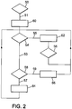
- FIG. 2 depicts a flow chart identifying activities consistent with an exemplary system 10 of the present invention.
- loss of cabin pressurization at high altitude activates flow of complementary oxygen to persons on-board the aircraft (block 60).
- Branch 51 corresponds to condition of detection of loss cabin pressurization fulfilled.
- Depressurization of the aircraft may be sensed in any suitable manner, either centrally for all passengers or more locally for a particular passenger or group of passengers, in particular with the cabin altitude sensor 11.
- the controller 20 activates the initiator 5. More generally, flow activation may be controlled by one or more computerized controllers 20 (see FIG. 1 ) to which the sensed depressurization signals are communicated, and oxygen may be supplied by any suitable source 14 such as, but not limited to, one or more oxygen bottles.
- Controller 20 additionally is configured to receive information relating to the fullness of buffer or reservoir 40 associated with each particular face mask 30 (block 54) from the sensor 26. If reservoir 40 is full of oxygen (branch 55), controller 20 signals delivery valve (or delivery valve) 22 to close (block 62). When delivery valve 22 closes, oxygen no longer flows from source 14 to (full) reservoir 40, hence avoiding valuable oxygen being shunted to the cabin environment 2 and thereby wasted. By contrast, if reservoir 40 is not full of oxygen (branch 53), controller 20 causes or permits delivery valve 22 to remain open, thus allowing oxygen to flow from source 14 to reservoir 40 (block 64) in the first supply mode. Such oxygen flow may occur at any desired rate, typically--but not necessarily--as functions of the altitude and descent rate of the aircraft.
- the flow of oxygen is adjusted between a low flow (about 3 litres per minute) and a high flow (about 40 litres per minute) depending on the aircraft altitude (and its derivative function the descent rate), the cabin altitude, the composition of the exhalation gas of the user, the breathing frequency of the user and the blood oxygen saturation of the user.
- FIG. 1 illustrates the exemplary system 10 as used for at least two passengers.
- each face mask 30 will include the reservoir 40 attached or otherwise capable of communicating breathing gas to the face mask 30.
- each reservoir 40 will incorporate the sensor 26 and be connected in fluid communication with source of breathing gas 14 via the delivery valve 22 and tubing 4.
- each mask 30 of a presently-preferred system 10 is associated with a reservoir 40 and a delivery valve 22, with the system 10 being scalable for multiple masks 30 within an aircraft 2.
- Each mask 30 also could be associated with a separate controller 20 and oxygen source 14, although advantageously the depicted controller 20 and source 14 are not dedicated to a single mask 30 but rather are associated with multiple masks 30 within the aircraft.
- Reservoir 40 may be of any desired size, shape, and construction. It may, for example, take the form of a bag similar to that described in the Cannon patent. As an alternative example, reservoir 40 may be a bellows-type accumulator (see FIG. 3A, 3B ). Some versions of reservoir 40 may (but need not necessarily) be sized so as to store a quantity of oxygen sufficient to allow recovery of even a deeply-desaturated passenger.
- sensor 26 is configured to sense whether its associated reservoir 40 is, or is not, full of oxygen. For these versions, therefore, sensor 26 need only provide a binary output (FULL/NOT FULL) to controller 20.
- sensor 26 may be adapted to provide more precise information respecting reservoir 40--e.g. that reservoir 40 is 86% full of oxygen, or within a range of 20-40% full of oxygen, etc. This more-precise information as provided to controller 20 could allow determination of certain breathing characteristics of the passenger such as breathing rate or inhalation speed, which in turn could be used to allow inferences as to whether the passenger is hyperventilating or unconscious, as examples, in order to adjust the flow of breathing gas provided to the user.
- Information supplied by sensors 26 additionally may be relayed to the aircraft crew for determination of the number of passengers breathing through masks 30, which could be compared against flight manifests as a check as to whether any passengers seem not to be using masks 30.
- Delivery valve 22 may alone, or together with other components, control oxygen delivery in any suitable manner.
- exemplary delivery controls include pulse-width modulation (PWM) of oxygen flow, variable valves, or variable upstream pressures through orifices (for instance controlling pressure downstream the pressure regulator 18).
- PWM pulse-width modulation
- Vari valves variable valves
- variable upstream pressures through orifices
- the delivery 22 may be controlled by the controller 20 both in order to fulfil two functions, adjusting the continuous flow of breathing gas and to interrupt the flow of breathing gas when the filling threshold of the reservoir 40 (preferably the reservoir 40 is dull) is reached. And, the continuous flow of breathing gas supplying each reservoir 40 may be individually adjusted based on characteristics sensed depending on the user (for instance, blood saturation or breathing rate, inhalation speed ).
- the delivery valve 22 may be controlled by the controller 20 in order to fulfil the function of interrupting the flow of breathing gas when the filling threshold of the reservoir 40 (preferably the reservoir 40 is full) is reached whereas the controller 20 controls the regulator 18 to adjust the continuous flow.
- the continuous flow may be adjusted by adjusting the pressure downstream the regulator 18.
- the regulator 18 is a real-time controlled regulator and a calibrated is preferably provided in tubing 4 or in the delivery valve 22.
- the continuous flow of breathing gas is adjusted at the same value for all the face masks 30 supplied by the regulator 18. But, the continuous flow can be independently interrupted by the delivery valve 22 for each face mask 30.
- each reservoir 40 may accumulate an amount of oxygen greater than would be present should the minimum oxygen delivery per unit time be employed (as per federal U.S. regulations).
- at least one version of reservoir 40 may accumulate one liter of oxygen.
- Sensors 26 may be of any suitable type. Examples of possible sensors 26 include micro-switches, internal pressure sensors, laser distance sensors, lanyards (see FIG. 3A, 3B ) which may become taut so as to change the state of an object, etc. A sensor 26 may be sampled at any desired time intervals in order to obtain fullness information respecting reservoir 40 as a function of time.
- sensor 26 is configured to provide only binary outlet (FULL/NOT FULL)
- hysteresis could be included in the detection circuitry to present nuisance (i.e. small, frequent) top-ups of reservoir 40 due to events such as signal noise, small leaks, or otherwise.
- the continuous flow is not resumed (block 64) just when the filling reservoir sensed by the sensor 26 is below a first threshold of filling which triggers the closing of the delivery valve 22 (block 62).
- the filling reservoir sensed by the sensor 26 must be lower than a second threshold (block 56) before resuming the continuous flow (block 64).
- Controller 20 could be programmed to query sensor 26, or sensor 26 could be configured to communicate information to controller 20 at fixed or variable intervals even if not having received a query from the controller 20. Any communication described herein that may be accomplished electronically may be performed either wirelessly or with wires.
- systems of the invention may operate in a second (emergency) supply mode (block 66), preferably a smoke-prevention mode in the illustrated. If smoke, or more generally toxic gas in the cabin ambient air 2 is detected (block 58) by the fume sensor 8, the controller 20 controls the delivery valve 22 (or in variant the regulator 18) in the second (emergency) supply mode (block 66) along branch 59, instead of the first (main) supply mode (block 64) along branch 57. In such second (emergency) supply mode the oxygen delivery rate would not necessarily be dependent on aircraft altitude and descent rate, but instead could be chosen so as to maintain each reservoir 40 as full at all times.
- the oxygen delivery rate in the second (emergency) supply mode is maximum and preferably higher or equal to the high flow in the first (main) supply mode (for instance, about 40 litres per minute).
- This approach would allow the reservoir 40 to accumulate sufficient oxygen to accommodate the entire breathing cycle of the passenger, even at peak demand, so as to prevent the passenger from breathing any smoky cabin air.
- the controller 20 controls the delivery valve 22 to adjust the continuous flow of breathing gas supplying the associated reservoir 40, preferably in the second continuous mode the delivery valve 22 stays fully open. And, in the first continuous mode, if the delivery valve 22 is an/off valve, the rate during which the delivery valve 22 is open may be adjusted in order to adjust the continuous flow of breathing gas supplying the associated reservoir 40 between the low flow and the high flow.
- pressure downstream regulator may vary between a low absolute pressure (for instance 1.5 bar) and a high pressure (for instance 6 bar), and in the second mode the regulator 18 may be controlled to set the high pressure below the regulator 18 in tubing 4.
- FIG. 3A and FIG. 3B illustrate a bellows-type accumulator forming reservoir 40.
- Such a reservoir may occupy a smaller space compared with conventional bags yet have a similar volumetric capacity.
- the reservoir 40 extends between a first longitudinal end 40a and a second longitudinal end 40b and has an internal volume 42.
- the reservoir 40 is connected to the face mask 30 through the first longitudinal end 40a.
- the reservoir 40 is connected to the second tubing 4B through the second longitudinal end 40b. Connection to the second tubing 4B located near the second longitudinal end 40b may allow second tubing 4B to facilitate unfurling of reservoir 40 as it inflates in use. In either situation, second tubing 4B preferably attaches elsewhere than at an end of a reservoir bag distal from the face mask (as occurs conventionally).
- the reservoir could be connected to the second tubing 4B near the first longitudinal end 40a. Connection located near the first longitudinal end 40a be beneficial at least in that second tubing 4B could be attached directly to the inlet valve 32 at a rear of face mask 30 and thus would not affect inflation and deflation of the reservoir 40. In particular, the reservoir 40 would not need to counteract the weight of second tubing 4B when it deflates. Also, when face mask 30 and the reservoir 40 are stowed, second tubing 4B would not pull on reservoir 40 and thus disturb its positioning and arrangement.
- the exemplary bellows of FIGS. 3A, 3B contains four pleats 44 and may have circular cross-section.
- Reservoir 40 may be formed differently than as shown, however; if a bellows, reservoir 40 additionally may have more or fewer than four pleats 44 and need not necessarily have circular cross-section.
- reservoir 40 is deflated, consistent with its status when stowed. Reservoir 40 is not positioned within mask 14 and hence should not impede donning of the face mask 30 by a passenger.
- the configuration of reservoir 40 allows easy inflation of the bellows in a volume-efficient design. Stated differently, a bellows-type reservoir 40 creates a relatively large inflated volume 42 for a relatively small two-dimensional footprint.
- reservoir 40 be made of supple material similar to that of conventional reservoir bags. More robust material may be used instead, however. Alternatively or additionally, reservoir 40 may be reinforced using a plastic backing plate 46 at the second longitudinal end 40b.
- Strings or threaded tethers conceivably could be utilized to prevent over-extension or burst of reservoir 40 when pressurization is desired.
- Bellows-type reservoirs need not be stored within cups of face masks. They likewise need not be folded--or need not be folded as compactly as are conventional bags, hence reducing any likelihood that the reservoirs will fail to inflate appropriately. Moreover, employing a bellows additionally creates a buffer (reservoir) configured to adapt better to peak instantaneous flow of the dynamic breathing of a passenger (or crewmember).
- Reservoir 40 may be made of flexible, relatively thin plastic material, as is conventional.
- the reservoir 40 may be formed of material sufficient to allow them to be pressurized, generating reduced envelopes as compared to conventional unpressurized bags. Inflation and deflation of the bellows further may furnish to crewmembers better visual indication of the delivery of respiratory gas to and consumption of the gas by passengers.
- the senor 26 comprises a switch 24 and a lanyard 25.
- the lanyard (string) 25 has a first lanyard end 25a fixed to the first longitudinal end 40a of the reservoir 40 and a second lanyard end 25b connected to the second longitudinal end 40b of the reservoir 40 through the switch (microswitch) 24.
- the extension of the reservoir 40 is roughly linearly proportional to the volume of gas within.
- the lanyard 25 pulls on and activates the switch 24.
- the figures 3A, 3B demonstrates an extension of the reservoir 40 of bellows-type when filling, but this could also be applied to a radial expansion, in particular of the classic 'bag' type reservoir.
- the senor 26 comprise a laser/reflector system with a pulse and time delay measurement could determine the distance of the reflector from the laser and give an almost continuous scale of 'fullness' of the reservoir as a function of distance.
- One amongst the laser and the reflector would be fixed near the first longitudinal end 40a, preferably to the face mask 30 and the other to the second longitudinal end 40b, preferably to the backing plate 46.
- FIGS. 4A and 4B illustrate another variant.
- the reservoir 40 has a flexible bag 48 of classic style.
- the sensor 26 comprises a strain gauge 36 integrated into the wall of the flexible bag 48. As the bag inflates it stretches slightly, which is detected by the strain gauge 36.
- the information may be transmitted between the sensor 26 and the controller 20 by electromagnetic wave.
- the information between the sensors 26 and the controller 20 may be transmitted by a RFID module 38 that changes its response based on the filling state of the reservoir 40. That means the RFID module 38 is used to power and read the sensor 26.
- This RFID antenna of the RFID module 38 is preferably encapsulated in the wall of the reservoir 40 or the face mask 30.
- the transmitter of the RFID module 38 is connected to the controller 20.
- the information between sensors 26 and the controller 20 may be transmitted by wire, preferably which directly links the sensors 26 to the controller 20, the wires being preferably encapsulated in the wall of the reservoir and the tubing 4.
- the information between sensors 26 and the controller 20 may be transmitted by waves such as radio, Bluetooth, WiFi powered by a battery.
- FIGS. 5A and 5B illustrate another variant.
- the sensor 26 comprises inlet valve 32 and a motion detector 33.
- the inlet valve 32 is of check valve type urged by a spring 31 in closed position.
- the inlet valve 32 is preferably of soft silicon. As the reservoir bag 40 inflates to the maximum then a slight positive pressure is exerted on the valve, causing the soft silicon to deform. This deformation could be detected by a Hall Effect sensor, an optical sensor or otherwise.
- the sensor 26 may include sensors to measure the flow from the tubing 4B entering within the reservoir 40 and the flow exiting the reservoir toward the face mask 30 (through the inlet valve 32), integrating the difference along the time. Indeed, the variation of the volume of gas inside the reservoir is equal to the volume entered minus the volume exited.
- Such flow sensors may be spirometer, venture meter, orifice plate, or any other suitable technology.
- references to "oxygen” herein need not necessarily refer to gases containing 100% oxygen, but may also refer to other breathing gases containing at least some oxygen.
Claims (15)
- System (10) zum Abgeben von Atemgas an Passagiere an Bord eines Flugzeugs, umfassend:eine Quelle von Atemgas (14),wenigstens eine Gesichtsmaske (30) für Passagiere,ein Reservoir (40), welches jeweils einer Gesichtsmaske (30) zugeordnet ist,ein Abgabeventil (22) für jede Gesichtsmaske (30), wobei das Abgabeventil (22) zwischen der Quelle (14) von Atemgas und dem Reservoir (40) angeordnet ist, wobei das Reservoir (40) zwischen dem Abgabeventil (22) und der Gesichtsmaske (30) angeordnet ist, undeine Steuereinheit (20), welche dazu eingerichtet ist, das Abgabeventil (22) zu steuern, um dem Reservoir (40) Atemgas bereitzustellen,dadurch gekennzeichnet, dass das System ferner umfasst:einen Sensor (26), welcher jeweils einem Reservoir (40) zugeordnet ist und dazu eingerichtet ist, eine Befüllung des Reservoirs (40) zu erfassen, unddie Steuereinheit (20) dazu eingerichtet ist, das Abgabeventil (22) in einem kontinuierlichen Zuführmodus zu steuern, um eine kontinuierliche Strömung von Atemgas (64) bereitzustellen und um die kontinuierliche Strömung von Atemgas (64) zu unterbrechen (62), wenn die durch den Sensor (26) erfasste Befüllung ein Befüllungsschwellenwert (55) ist.
- System nach Anspruch 1, wobei:der kontinuierliche Zuführmodus ein erster kontinuierlicher Zuführmodus (64) ist,die Steuereinheit (20) dazu eingerichtet ist, die Strömung von Atemgas in einem zweiten kontinuierlichen Zuführmodus (66) höher als in dem ersten kontinuierlichen Zuführmodus (64) einzustellen.
- System nach dem vorhergehenden Anspruch, wobei die Steuereinheit dazu eingerichtet ist, auf Grundlage eines zweiten Parameters (8) zwischen dem ersten kontinuierlichen Zuführmodus (64) und dem zweiten kontinuierlichen Zuführmodus (66) zu schalten (26), wobei der zweite Parameter (8) ein Vorhandensein von toxischem Gas und/oder Brandgasen in einem Umgebungsgas (2) umfasst.
- System nach einem der Ansprüche 2 und 3, wobei:die Steuereinheit (20) dazu eingerichtet ist, die Strömung von Atemgas in dem ersten kontinuierlichen Zuführmodus (64) zwischen einer geringen Strömung und einer hohen Strömung einzustellen, unddie Steuereinheit (20) dazu eingerichtet ist, die Strömung von Atemgas in dem zweiten kontinuierlichen Zuführmodus (66) höher als oder gleich wie die hohe Strömung einzustellen.
- System nach einem der vorhergehenden Ansprüche, wobei die Steuereinheit (20) dazu eingerichtet ist, die Strömung von Atemgas bei mehreren Nicht-Null-Werten in dem kontinuierlichen Zuführmodus (64) auf Grundlage wenigstens eines ersten Parameters (11, 12, 13) einzustellen.
- System nach Anspruch 5, wobei:der Sensor (26) dazu eingerichtet ist, wenigstens zwei verschiedene Werte einer Reservoirbefüllung zu erfassen, unddie Steuereinheit (20) dazu eingerichtet ist, auf Grundlage der Werte einer durch den Sensor (26) erfassten Reservoirbefüllung wenigstens einen ersten Parameter zu bestimmen.
- System nach einem der vorhergehenden Ansprüche, wobei der Befüllungsschwellenwert (54) eine Vollheit des Reservoirs ist.
- System nach einem der vorhergehenden Ansprüche, wobei das Reservoir (40) ein balgartiger Reservoirbeutel ist.
- System nach einem der vorhergehenden Ansprüche, wobei:das System (10) ein RFID-Modul (38) umfasst, welches mit dem Sensor (26) verbunden ist,das RFID-Modul (38) dazu eingerichtet ist, den Sensor (26) anzutreiben und auszulesen, unddas RFID-Modul (38) dazu eingerichtet ist, mit der Steuereinheit (20) zu kommunizieren.
- System nach einem der vorhergehenden Ansprüche, wobei das System umfasst:eine Mehrzahl von Gesichtsmasken (30),eine Mehrzahl von Reservoirs (40), wobei jedes Reservoir (40) einer der Mehrzahl von Gesichtsmasken (30) zugeordnet ist,eine Mehrzahl von Sensoren (26), wobei jeder Sensor (26) jeweils einem Reservoir (40) zugeordnet ist und dazu eingerichtet ist, den Befüllungsschwellenwert in dem zugeordneten Reservoir zu erfassen, unddie Steuereinheit (20) dazu eingerichtet ist, die kontinuierliche Strömung (64) von Atemgas von der Quelle (14) zu jedem Reservoir (40) zu steuern und die kontinuierliche Strömung von Atemgas zu dem Reservoir (40) zu unterbrechen (62), dessen zugeordneter Sensor (26) den Befüllungsschwellenwert (55) in dem Reservoir erfasst.
- Verfahren zum Abgeben von Atemgas an Passagiere an Bord eines Flugzeugs unter Verwendung eines Systems nach einem der Ansprüche 1 bis 10, umfassend:Zuführen einer kontinuierlichen Strömung von Atemgas (64) zu einem Reservoir (40), welches einer Gesichtsmaske (30) zugeordnet ist,dadurch gekennzeichnet, dass das Verfahren ferner umfasst:Erfassen (26) einer Befüllung des Reservoirs (40),Unterbrechen (62) der kontinuierlichen Strömung von Atemgas, wenn ein Befüllungsschwellenwert erreicht ist (55).
- Verfahren nach Anspruch 11, wobei der Befüllungsschwellenwert eine Vollheit des Reservoirs ist.
- Verfahren nach einem der Ansprüche 11 bis 12, umfassend:
Einstellen der Strömung von Atemgas bei mehreren Nicht-Null-Werten in dem kontinuierlichen Zuführmodus (64) auf Grundlage wenigstens eines Parameters, welcher ausgewählt ist aus der Gruppe, bestehend aus einer Kabinenhöhe (11), einer Flugzeughöhe (12), einer Zusammensetzung eines Ausatmungsgases (13), einer Atemfrequenz und einer Blutsauerstoffsättigung (15). - Verfahren nach einem der Ansprüche 11 bis 13, wobei der kontinuierliche Zuführmodus ein erster kontinuierlicher Zuführmodus (64) ist und der wenigstens eine Parameter wenigstens ein erster Parameter ist und das Verfahren umfasst:Einstellen der Strömung von Atemgas zwischen einer geringen Strömung und einer hohen Strömung in dem ersten kontinuierlichen Zuführmodus undFestlegen der Strömung von Atemgas auf eine vorbestimmte Strömung in einem zweiten kontinuierlichen Zuführmodus (66), wobei die vorbestimmte Strömung höher als oder gleich wie die hohe Strömung ist.
- Verfahren nach Anspruch 14, umfassend:
Schalten (26) zwischen dem ersten kontinuierlichen Zuführmodus (64) und dem zweiten kontinuierlichen Zuführmodus (66) auf Grundlage eines zweiten Parameters (8).
Applications Claiming Priority (1)
| Application Number | Priority Date | Filing Date | Title |
|---|---|---|---|
| US201862643489P | 2018-03-15 | 2018-03-15 |
Publications (2)
| Publication Number | Publication Date |
|---|---|
| EP3539620A1 EP3539620A1 (de) | 2019-09-18 |
| EP3539620B1 true EP3539620B1 (de) | 2021-06-09 |
Family
ID=66041378
Family Applications (1)
| Application Number | Title | Priority Date | Filing Date |
|---|---|---|---|
| EP19305311.3A Active EP3539620B1 (de) | 2018-03-15 | 2019-03-14 | System und verfahren zur abgabe von atemgas an passagiere an bord eines flugzeugs |
Country Status (5)
| Country | Link |
|---|---|
| US (1) | US11338158B2 (de) |
| EP (1) | EP3539620B1 (de) |
| CN (1) | CN110270023B (de) |
| BR (1) | BR102019005110A2 (de) |
| CA (1) | CA3037020A1 (de) |
Families Citing this family (7)
| Publication number | Priority date | Publication date | Assignee | Title |
|---|---|---|---|---|
| US11172845B1 (en) * | 2020-07-20 | 2021-11-16 | Spotlight Labs | Combined exhaled air and environmental gas sensor apparatus |
| JP6932408B1 (ja) | 2020-09-25 | 2021-09-08 | 株式会社岩谷技研 | 気球用のキャビン |
| US20220348352A1 (en) * | 2021-04-30 | 2022-11-03 | The Boeing Company | Aircraft mask monitoring system |
| CN113562181B (zh) * | 2021-07-29 | 2023-04-18 | 北京安达维尔航空设备有限公司 | 一种新型长航时乘员供氧装置 |
| CN114476078B (zh) * | 2022-03-16 | 2022-09-09 | 湖南文理学院 | 一种飞机座舱内集成供氧系统 |
| WO2024005889A1 (en) * | 2022-06-29 | 2024-01-04 | Rescue Air Systems, Inc. | Method and system of automatically modifying a rate of filling an air bottle with breathable air in a firefighter air replenishment system based on flow rate detection thereof |
| WO2024023156A1 (en) * | 2022-07-29 | 2024-02-01 | Aviation Works Limited | A system for supplying a breathable gas to a user |
Family Cites Families (32)
| Publication number | Priority date | Publication date | Assignee | Title |
|---|---|---|---|---|
| US2248349A (en) * | 1939-12-14 | 1941-07-08 | Air Reduction | Inhalation device for use in aviation at high altitudes |
| US4098271A (en) * | 1975-09-29 | 1978-07-04 | Mcdonnell Douglas Corporation | Oxygen supply system and flow indicator |
| SE465497B (sv) * | 1989-11-24 | 1991-09-23 | Minco Ab | Anordning foer studium av en persons lungfunktion |
| US5537995A (en) * | 1990-04-03 | 1996-07-23 | Den Norske Stats Oljeselskap A.S. | Breathing system having breathing bag and supplemental gas dosing controls |
| US5265597A (en) * | 1992-07-01 | 1993-11-30 | Puritan-Bennett Corporation | Passenger oxygen mask having a plurality of fingers and recesses for mounting the mask to an oxygen bag |
| US5408995A (en) * | 1993-04-16 | 1995-04-25 | Figgie International Inc. | Continuous flow passenger oxygen dispensing unit |
| US5343859A (en) * | 1993-06-17 | 1994-09-06 | Puritan-Bennett Corporation | Passenger oxygen mask having internal flow confirmation balloon |
| SE9400992L (sv) * | 1994-03-24 | 1995-05-02 | Siemens Elema Ab | Andningsgassystem med en trycköverförande bäljanordning mellan andningskretsen och drivgasapparaten |
| SE9402537L (sv) * | 1994-07-20 | 1996-01-21 | Siemens Elema Ab | Narkossystem |
| DE19782256C2 (de) | 1997-02-06 | 2002-08-14 | Smc Kk | Pneumatischer Regler |
| US6213120B1 (en) * | 1997-08-21 | 2001-04-10 | Instrumentarium Corporation | Device and method for determining gas volume and volumetric changes in a ventilator |
| US7055520B2 (en) * | 2001-01-17 | 2006-06-06 | David Swisa | Device and method for detecting the flow of a gas |
| FR2832639B1 (fr) * | 2001-11-28 | 2004-07-02 | Intertechnique Sa | Procede et dispositif de protection des passagers d'un aeronef contre l'hypoxie |
| CA2522623C (en) * | 2003-02-19 | 2014-01-28 | Joseph Fisher | A new method of measuring cardiac related parameters non-invasively with spontaneous and controlled ventilation |
| FR2858560B1 (fr) | 2003-08-04 | 2005-09-09 | Air Liquide | Circuit de fourniture d'oxygene a des passagers d'un aeronef |
| DE102004040740A1 (de) * | 2004-08-21 | 2006-02-23 | Viasys Healthcare Gmbh | Gasreservoirbeutel, Verteilergehäuse, Beatmungsmaske sowie Beatmungsverfahren |
| US7588032B2 (en) * | 2004-12-08 | 2009-09-15 | Be Intellectual Proeprty, Inc. | Oxygen conservation system for commercial aircraft |
| DE102004063698B4 (de) * | 2004-12-28 | 2010-02-04 | Dae Systems Gmbh | Notsauerstoffsystem für Flugzeugpassagiere |
| WO2006089427A1 (en) * | 2005-02-25 | 2006-08-31 | Thornhill Research Inc. | Method and apparatus for inducing and controlling hypoxia |
| DE102005023393B4 (de) * | 2005-05-20 | 2007-02-15 | Dräger Safety AG & Co. KGaA | Druckluft-Atemgerät |
| DE102005023392B3 (de) * | 2005-05-20 | 2006-06-08 | Dräger Safety AG & Co. KGaA | Druckluft-Atemgerät |
| US7604019B2 (en) | 2005-07-22 | 2009-10-20 | B/E Intellectual Property | Electromechanical regulator with primary and backup modes of operation for regulating passenger oxygen |
| DE602006015714C5 (de) | 2006-04-13 | 2015-07-02 | Zodiac Aerotechnics | Atemgaszufuhrkreis für ein mit passagieren besetztes flugzeug |
| WO2008010015A1 (en) | 2006-07-12 | 2008-01-24 | Intertechnique | A respiratory gas supply circuit to feed crew members and passengers of an aircraft with oxygen |
| EP2152578B1 (de) * | 2007-05-14 | 2012-08-29 | Airbus Operations GmbH | Sauerstoffzufuhrsystem für flugzeuge |
| US8474456B2 (en) * | 2008-05-30 | 2013-07-02 | Intertechnique, S.A. | Oxygen breathing mask |
| EP2446930B1 (de) | 2010-10-26 | 2016-07-13 | Zodiac Aerotechnics | Sauerstoffatemvorrichtung mit integriertem flexiblem puffer |
| US8733352B2 (en) | 2011-09-30 | 2014-05-27 | The Boeing Company | Pulse oxygen system |
| US10293193B2 (en) | 2012-06-20 | 2019-05-21 | B/E Aerospace, Inc. | Aircraft lavatory emergency oxygen device |
| US10682489B2 (en) * | 2013-11-20 | 2020-06-16 | Transunit Ab | Turbine ventilator system and method |
| US20170007859A1 (en) | 2014-02-26 | 2017-01-12 | Zodiac Aerotechnics | Gas pressure reducer with electrically-powered master system |
| GB201411199D0 (en) | 2014-06-24 | 2014-08-06 | Avia Tech Ltd | Emergency oxygen supply system |
-
2019
- 2019-03-14 US US16/352,947 patent/US11338158B2/en active Active
- 2019-03-14 EP EP19305311.3A patent/EP3539620B1/de active Active
- 2019-03-15 CN CN201910198492.2A patent/CN110270023B/zh active Active
- 2019-03-15 CA CA3037020A patent/CA3037020A1/en active Pending
- 2019-03-15 BR BR102019005110-8A patent/BR102019005110A2/pt unknown
Non-Patent Citations (1)
| Title |
|---|
| None * |
Also Published As
| Publication number | Publication date |
|---|---|
| CA3037020A1 (en) | 2019-09-15 |
| US20190282839A1 (en) | 2019-09-19 |
| EP3539620A1 (de) | 2019-09-18 |
| BR102019005110A2 (pt) | 2019-10-01 |
| CN110270023B (zh) | 2022-11-15 |
| CN110270023A (zh) | 2019-09-24 |
| US11338158B2 (en) | 2022-05-24 |
Similar Documents
| Publication | Publication Date | Title |
|---|---|---|
| EP3539620B1 (de) | System und verfahren zur abgabe von atemgas an passagiere an bord eines flugzeugs | |
| EP3533495B1 (de) | Dosierte sauerstoffsysteme mit förderrohr-antiblockiermerkmalen und verfahren zur förderung von atemgas | |
| US7588032B2 (en) | Oxygen conservation system for commercial aircraft | |
| US8517018B2 (en) | Oxygen supply system for an aircraft | |
| US4638791A (en) | Apparatus and methods for providing rapid protection from accelerative forces experienced by aircraft crew members | |
| US11291868B2 (en) | Pulse saturation oxygen delivery system and method | |
| US4440166A (en) | Electrically and mechanically controllable closed cycle respirator | |
| JP6067847B2 (ja) | 航空機化粧室用非常時酸素装置 | |
| CN103415325B (zh) | 飞行器流量调节器及稀释调节方法 | |
| US11541974B2 (en) | Low pressure respiration gas delivery method | |
| US5226410A (en) | Physiological safety device for aircraft pilots | |
| Gradwell et al. | Oxygen systems, pressure cabin and clothing | |
| US9016278B2 (en) | Regulation valve for a life support system | |
| EP2550994A1 (de) | Regelventil für ein Lebenserhaltungssystem | |
| EP3582836B1 (de) | System zur gasabgabe mit gaskonservierer | |
| EP3791933B1 (de) | System zur abgabe von atemgas an passagiere | |
| Gradwell | Oxygen equipment and pressure clothing |
Legal Events
| Date | Code | Title | Description |
|---|---|---|---|
| PUAI | Public reference made under article 153(3) epc to a published international application that has entered the european phase |
Free format text: ORIGINAL CODE: 0009012 |
|
| STAA | Information on the status of an ep patent application or granted ep patent |
Free format text: STATUS: THE APPLICATION HAS BEEN PUBLISHED |
|
| AK | Designated contracting states |
Kind code of ref document: A1 Designated state(s): AL AT BE BG CH CY CZ DE DK EE ES FI FR GB GR HR HU IE IS IT LI LT LU LV MC MK MT NL NO PL PT RO RS SE SI SK SM TR |
|
| AX | Request for extension of the european patent |
Extension state: BA ME |
|
| RIN1 | Information on inventor provided before grant (corrected) |
Inventor name: KLOCKIEWICZ, FLORIAN Inventor name: RITTNER, WOLFGANG Inventor name: WALKER, STUART Inventor name: URBAIN, JOAN Inventor name: GILLOTIN, VINCENT Inventor name: DELPRAT, JEAN-BAPTISTE Inventor name: GRETER, VINCENT Inventor name: WENZEL, JUERGEN |
|
| STAA | Information on the status of an ep patent application or granted ep patent |
Free format text: STATUS: REQUEST FOR EXAMINATION WAS MADE |
|
| 17P | Request for examination filed |
Effective date: 20200304 |
|
| RBV | Designated contracting states (corrected) |
Designated state(s): AL AT BE BG CH CY CZ DE DK EE ES FI FR GB GR HR HU IE IS IT LI LT LU LV MC MK MT NL NO PL PT RO RS SE SI SK SM TR |
|
| GRAP | Despatch of communication of intention to grant a patent |
Free format text: ORIGINAL CODE: EPIDOSNIGR1 |
|
| STAA | Information on the status of an ep patent application or granted ep patent |
Free format text: STATUS: GRANT OF PATENT IS INTENDED |
|
| RIC1 | Information provided on ipc code assigned before grant |
Ipc: A62B 7/14 20060101AFI20200714BHEP |
|
| INTG | Intention to grant announced |
Effective date: 20200817 |
|
| RIN1 | Information on inventor provided before grant (corrected) |
Inventor name: WENZEL, JUERGEN Inventor name: DELPRAT, JEAN-BAPTISTE Inventor name: GILLOTIN, VINCENT Inventor name: KLOCKIEWICZ, FLORIAN Inventor name: RITTNER, WOLFGANG Inventor name: GRETER, VINCENT Inventor name: WALKER, STUART Inventor name: URBAIN, JOAN |
|
| GRAJ | Information related to disapproval of communication of intention to grant by the applicant or resumption of examination proceedings by the epo deleted |
Free format text: ORIGINAL CODE: EPIDOSDIGR1 |
|
| STAA | Information on the status of an ep patent application or granted ep patent |
Free format text: STATUS: REQUEST FOR EXAMINATION WAS MADE |
|
| INTC | Intention to grant announced (deleted) | ||
| RAP1 | Party data changed (applicant data changed or rights of an application transferred) |
Owner name: SAFRAN AEROTECHNICS |
|
| GRAP | Despatch of communication of intention to grant a patent |
Free format text: ORIGINAL CODE: EPIDOSNIGR1 |
|
| STAA | Information on the status of an ep patent application or granted ep patent |
Free format text: STATUS: GRANT OF PATENT IS INTENDED |
|
| INTG | Intention to grant announced |
Effective date: 20210115 |
|
| GRAS | Grant fee paid |
Free format text: ORIGINAL CODE: EPIDOSNIGR3 |
|
| GRAA | (expected) grant |
Free format text: ORIGINAL CODE: 0009210 |
|
| STAA | Information on the status of an ep patent application or granted ep patent |
Free format text: STATUS: THE PATENT HAS BEEN GRANTED |
|
| AK | Designated contracting states |
Kind code of ref document: B1 Designated state(s): AL AT BE BG CH CY CZ DE DK EE ES FI FR GB GR HR HU IE IS IT LI LT LU LV MC MK MT NL NO PL PT RO RS SE SI SK SM TR |
|
| REG | Reference to a national code |
Ref country code: GB Ref legal event code: FG4D |
|
| REG | Reference to a national code |
Ref country code: CH Ref legal event code: EP Ref country code: AT Ref legal event code: REF Ref document number: 1399972 Country of ref document: AT Kind code of ref document: T Effective date: 20210615 |
|
| REG | Reference to a national code |
Ref country code: DE Ref legal event code: R096 Ref document number: 602019005264 Country of ref document: DE |
|
| REG | Reference to a national code |
Ref country code: IE Ref legal event code: FG4D |
|
| REG | Reference to a national code |
Ref country code: LT Ref legal event code: MG9D |
|
| PG25 | Lapsed in a contracting state [announced via postgrant information from national office to epo] |
Ref country code: BG Free format text: LAPSE BECAUSE OF FAILURE TO SUBMIT A TRANSLATION OF THE DESCRIPTION OR TO PAY THE FEE WITHIN THE PRESCRIBED TIME-LIMIT Effective date: 20210909 Ref country code: FI Free format text: LAPSE BECAUSE OF FAILURE TO SUBMIT A TRANSLATION OF THE DESCRIPTION OR TO PAY THE FEE WITHIN THE PRESCRIBED TIME-LIMIT Effective date: 20210609 Ref country code: HR Free format text: LAPSE BECAUSE OF FAILURE TO SUBMIT A TRANSLATION OF THE DESCRIPTION OR TO PAY THE FEE WITHIN THE PRESCRIBED TIME-LIMIT Effective date: 20210609 Ref country code: LT Free format text: LAPSE BECAUSE OF FAILURE TO SUBMIT A TRANSLATION OF THE DESCRIPTION OR TO PAY THE FEE WITHIN THE PRESCRIBED TIME-LIMIT Effective date: 20210609 |
|
| REG | Reference to a national code |
Ref country code: AT Ref legal event code: MK05 Ref document number: 1399972 Country of ref document: AT Kind code of ref document: T Effective date: 20210609 |
|
| REG | Reference to a national code |
Ref country code: NL Ref legal event code: MP Effective date: 20210609 |
|
| PG25 | Lapsed in a contracting state [announced via postgrant information from national office to epo] |
Ref country code: NO Free format text: LAPSE BECAUSE OF FAILURE TO SUBMIT A TRANSLATION OF THE DESCRIPTION OR TO PAY THE FEE WITHIN THE PRESCRIBED TIME-LIMIT Effective date: 20210909 Ref country code: LV Free format text: LAPSE BECAUSE OF FAILURE TO SUBMIT A TRANSLATION OF THE DESCRIPTION OR TO PAY THE FEE WITHIN THE PRESCRIBED TIME-LIMIT Effective date: 20210609 Ref country code: SE Free format text: LAPSE BECAUSE OF FAILURE TO SUBMIT A TRANSLATION OF THE DESCRIPTION OR TO PAY THE FEE WITHIN THE PRESCRIBED TIME-LIMIT Effective date: 20210609 Ref country code: RS Free format text: LAPSE BECAUSE OF FAILURE TO SUBMIT A TRANSLATION OF THE DESCRIPTION OR TO PAY THE FEE WITHIN THE PRESCRIBED TIME-LIMIT Effective date: 20210609 Ref country code: GR Free format text: LAPSE BECAUSE OF FAILURE TO SUBMIT A TRANSLATION OF THE DESCRIPTION OR TO PAY THE FEE WITHIN THE PRESCRIBED TIME-LIMIT Effective date: 20210910 |
|
| PG25 | Lapsed in a contracting state [announced via postgrant information from national office to epo] |
Ref country code: CZ Free format text: LAPSE BECAUSE OF FAILURE TO SUBMIT A TRANSLATION OF THE DESCRIPTION OR TO PAY THE FEE WITHIN THE PRESCRIBED TIME-LIMIT Effective date: 20210609 Ref country code: AT Free format text: LAPSE BECAUSE OF FAILURE TO SUBMIT A TRANSLATION OF THE DESCRIPTION OR TO PAY THE FEE WITHIN THE PRESCRIBED TIME-LIMIT Effective date: 20210609 Ref country code: SM Free format text: LAPSE BECAUSE OF FAILURE TO SUBMIT A TRANSLATION OF THE DESCRIPTION OR TO PAY THE FEE WITHIN THE PRESCRIBED TIME-LIMIT Effective date: 20210609 Ref country code: NL Free format text: LAPSE BECAUSE OF FAILURE TO SUBMIT A TRANSLATION OF THE DESCRIPTION OR TO PAY THE FEE WITHIN THE PRESCRIBED TIME-LIMIT Effective date: 20210609 Ref country code: RO Free format text: LAPSE BECAUSE OF FAILURE TO SUBMIT A TRANSLATION OF THE DESCRIPTION OR TO PAY THE FEE WITHIN THE PRESCRIBED TIME-LIMIT Effective date: 20210609 Ref country code: PT Free format text: LAPSE BECAUSE OF FAILURE TO SUBMIT A TRANSLATION OF THE DESCRIPTION OR TO PAY THE FEE WITHIN THE PRESCRIBED TIME-LIMIT Effective date: 20211011 Ref country code: ES Free format text: LAPSE BECAUSE OF FAILURE TO SUBMIT A TRANSLATION OF THE DESCRIPTION OR TO PAY THE FEE WITHIN THE PRESCRIBED TIME-LIMIT Effective date: 20210609 Ref country code: EE Free format text: LAPSE BECAUSE OF FAILURE TO SUBMIT A TRANSLATION OF THE DESCRIPTION OR TO PAY THE FEE WITHIN THE PRESCRIBED TIME-LIMIT Effective date: 20210609 Ref country code: SK Free format text: LAPSE BECAUSE OF FAILURE TO SUBMIT A TRANSLATION OF THE DESCRIPTION OR TO PAY THE FEE WITHIN THE PRESCRIBED TIME-LIMIT Effective date: 20210609 |
|
| PG25 | Lapsed in a contracting state [announced via postgrant information from national office to epo] |
Ref country code: PL Free format text: LAPSE BECAUSE OF FAILURE TO SUBMIT A TRANSLATION OF THE DESCRIPTION OR TO PAY THE FEE WITHIN THE PRESCRIBED TIME-LIMIT Effective date: 20210609 |
|
| REG | Reference to a national code |
Ref country code: DE Ref legal event code: R097 Ref document number: 602019005264 Country of ref document: DE |
|
| PLBE | No opposition filed within time limit |
Free format text: ORIGINAL CODE: 0009261 |
|
| STAA | Information on the status of an ep patent application or granted ep patent |
Free format text: STATUS: NO OPPOSITION FILED WITHIN TIME LIMIT |
|
| PG25 | Lapsed in a contracting state [announced via postgrant information from national office to epo] |
Ref country code: DK Free format text: LAPSE BECAUSE OF FAILURE TO SUBMIT A TRANSLATION OF THE DESCRIPTION OR TO PAY THE FEE WITHIN THE PRESCRIBED TIME-LIMIT Effective date: 20210609 |
|
| 26N | No opposition filed |
Effective date: 20220310 |
|
| PG25 | Lapsed in a contracting state [announced via postgrant information from national office to epo] |
Ref country code: AL Free format text: LAPSE BECAUSE OF FAILURE TO SUBMIT A TRANSLATION OF THE DESCRIPTION OR TO PAY THE FEE WITHIN THE PRESCRIBED TIME-LIMIT Effective date: 20210609 |
|
| PG25 | Lapsed in a contracting state [announced via postgrant information from national office to epo] |
Ref country code: IT Free format text: LAPSE BECAUSE OF FAILURE TO SUBMIT A TRANSLATION OF THE DESCRIPTION OR TO PAY THE FEE WITHIN THE PRESCRIBED TIME-LIMIT Effective date: 20210609 |
|
| PG25 | Lapsed in a contracting state [announced via postgrant information from national office to epo] |
Ref country code: MC Free format text: LAPSE BECAUSE OF FAILURE TO SUBMIT A TRANSLATION OF THE DESCRIPTION OR TO PAY THE FEE WITHIN THE PRESCRIBED TIME-LIMIT Effective date: 20210609 |
|
| REG | Reference to a national code |
Ref country code: CH Ref legal event code: PL |
|
| REG | Reference to a national code |
Ref country code: BE Ref legal event code: MM Effective date: 20220331 |
|
| PG25 | Lapsed in a contracting state [announced via postgrant information from national office to epo] |
Ref country code: LU Free format text: LAPSE BECAUSE OF NON-PAYMENT OF DUE FEES Effective date: 20220314 Ref country code: LI Free format text: LAPSE BECAUSE OF NON-PAYMENT OF DUE FEES Effective date: 20220331 Ref country code: IE Free format text: LAPSE BECAUSE OF NON-PAYMENT OF DUE FEES Effective date: 20220314 Ref country code: CH Free format text: LAPSE BECAUSE OF NON-PAYMENT OF DUE FEES Effective date: 20220331 |
|
| PG25 | Lapsed in a contracting state [announced via postgrant information from national office to epo] |
Ref country code: BE Free format text: LAPSE BECAUSE OF NON-PAYMENT OF DUE FEES Effective date: 20220331 |
|
| PGFP | Annual fee paid to national office [announced via postgrant information from national office to epo] |
Ref country code: FR Payment date: 20230222 Year of fee payment: 5 |
|
| PGFP | Annual fee paid to national office [announced via postgrant information from national office to epo] |
Ref country code: DE Payment date: 20230221 Year of fee payment: 5 |
|
| GBPC | Gb: european patent ceased through non-payment of renewal fee |
Effective date: 20230314 |
|
| PG25 | Lapsed in a contracting state [announced via postgrant information from national office to epo] |
Ref country code: GB Free format text: LAPSE BECAUSE OF NON-PAYMENT OF DUE FEES Effective date: 20230314 |
|
| PG25 | Lapsed in a contracting state [announced via postgrant information from national office to epo] |
Ref country code: GB Free format text: LAPSE BECAUSE OF NON-PAYMENT OF DUE FEES Effective date: 20230314 |