EP3539439A2 - Floor cleaning tool and method - Google Patents
Floor cleaning tool and method Download PDFInfo
- Publication number
- EP3539439A2 EP3539439A2 EP19172808.8A EP19172808A EP3539439A2 EP 3539439 A2 EP3539439 A2 EP 3539439A2 EP 19172808 A EP19172808 A EP 19172808A EP 3539439 A2 EP3539439 A2 EP 3539439A2
- Authority
- EP
- European Patent Office
- Prior art keywords
- cleaning tool
- floor cleaning
- roller
- floor
- housing
- Prior art date
- Legal status (The legal status is an assumption and is not a legal conclusion. Google has not performed a legal analysis and makes no representation as to the accuracy of the status listed.)
- Granted
Links
Images









Classifications
-
- A—HUMAN NECESSITIES
- A47—FURNITURE; DOMESTIC ARTICLES OR APPLIANCES; COFFEE MILLS; SPICE MILLS; SUCTION CLEANERS IN GENERAL
- A47L—DOMESTIC WASHING OR CLEANING; SUCTION CLEANERS IN GENERAL
- A47L9/00—Details or accessories of suction cleaners, e.g. mechanical means for controlling the suction or for effecting pulsating action; Storing devices specially adapted to suction cleaners or parts thereof; Carrying-vehicles specially adapted for suction cleaners
- A47L9/02—Nozzles
- A47L9/04—Nozzles with driven brushes or agitators
- A47L9/0455—Bearing means therefor
-
- A—HUMAN NECESSITIES
- A47—FURNITURE; DOMESTIC ARTICLES OR APPLIANCES; COFFEE MILLS; SPICE MILLS; SUCTION CLEANERS IN GENERAL
- A47L—DOMESTIC WASHING OR CLEANING; SUCTION CLEANERS IN GENERAL
- A47L11/00—Machines for cleaning floors, carpets, furniture, walls, or wall coverings
- A47L11/29—Floor-scrubbing machines characterised by means for taking-up dirty liquid
- A47L11/30—Floor-scrubbing machines characterised by means for taking-up dirty liquid by suction
- A47L11/302—Floor-scrubbing machines characterised by means for taking-up dirty liquid by suction having rotary tools
-
- A—HUMAN NECESSITIES
- A47—FURNITURE; DOMESTIC ARTICLES OR APPLIANCES; COFFEE MILLS; SPICE MILLS; SUCTION CLEANERS IN GENERAL
- A47L—DOMESTIC WASHING OR CLEANING; SUCTION CLEANERS IN GENERAL
- A47L11/00—Machines for cleaning floors, carpets, furniture, walls, or wall coverings
- A47L11/02—Floor surfacing or polishing machines
- A47L11/10—Floor surfacing or polishing machines motor-driven
- A47L11/14—Floor surfacing or polishing machines motor-driven with rotating tools
- A47L11/18—Floor surfacing or polishing machines motor-driven with rotating tools the tools being roll brushes
- A47L11/19—Parts or details of the brushing tools
-
- A—HUMAN NECESSITIES
- A47—FURNITURE; DOMESTIC ARTICLES OR APPLIANCES; COFFEE MILLS; SPICE MILLS; SUCTION CLEANERS IN GENERAL
- A47L—DOMESTIC WASHING OR CLEANING; SUCTION CLEANERS IN GENERAL
- A47L11/00—Machines for cleaning floors, carpets, furniture, walls, or wall coverings
- A47L11/40—Parts or details of machines not provided for in groups A47L11/02 - A47L11/38, or not restricted to one of these groups, e.g. handles, arrangements of switches, skirts, buffers, levers
- A47L11/4036—Parts or details of the surface treating tools
- A47L11/4041—Roll shaped surface treating tools
-
- A—HUMAN NECESSITIES
- A47—FURNITURE; DOMESTIC ARTICLES OR APPLIANCES; COFFEE MILLS; SPICE MILLS; SUCTION CLEANERS IN GENERAL
- A47L—DOMESTIC WASHING OR CLEANING; SUCTION CLEANERS IN GENERAL
- A47L11/00—Machines for cleaning floors, carpets, furniture, walls, or wall coverings
- A47L11/40—Parts or details of machines not provided for in groups A47L11/02 - A47L11/38, or not restricted to one of these groups, e.g. handles, arrangements of switches, skirts, buffers, levers
- A47L11/4036—Parts or details of the surface treating tools
- A47L11/4044—Vacuuming or pick-up tools; Squeegees
-
- A—HUMAN NECESSITIES
- A47—FURNITURE; DOMESTIC ARTICLES OR APPLIANCES; COFFEE MILLS; SPICE MILLS; SUCTION CLEANERS IN GENERAL
- A47L—DOMESTIC WASHING OR CLEANING; SUCTION CLEANERS IN GENERAL
- A47L11/00—Machines for cleaning floors, carpets, furniture, walls, or wall coverings
- A47L11/40—Parts or details of machines not provided for in groups A47L11/02 - A47L11/38, or not restricted to one of these groups, e.g. handles, arrangements of switches, skirts, buffers, levers
- A47L11/4075—Handles; levers
-
- A—HUMAN NECESSITIES
- A47—FURNITURE; DOMESTIC ARTICLES OR APPLIANCES; COFFEE MILLS; SPICE MILLS; SUCTION CLEANERS IN GENERAL
- A47L—DOMESTIC WASHING OR CLEANING; SUCTION CLEANERS IN GENERAL
- A47L11/00—Machines for cleaning floors, carpets, furniture, walls, or wall coverings
- A47L11/40—Parts or details of machines not provided for in groups A47L11/02 - A47L11/38, or not restricted to one of these groups, e.g. handles, arrangements of switches, skirts, buffers, levers
- A47L11/4077—Skirts or splash guards
-
- A—HUMAN NECESSITIES
- A47—FURNITURE; DOMESTIC ARTICLES OR APPLIANCES; COFFEE MILLS; SPICE MILLS; SUCTION CLEANERS IN GENERAL
- A47L—DOMESTIC WASHING OR CLEANING; SUCTION CLEANERS IN GENERAL
- A47L11/00—Machines for cleaning floors, carpets, furniture, walls, or wall coverings
- A47L11/40—Parts or details of machines not provided for in groups A47L11/02 - A47L11/38, or not restricted to one of these groups, e.g. handles, arrangements of switches, skirts, buffers, levers
- A47L11/408—Means for supplying cleaning or surface treating agents
-
- A—HUMAN NECESSITIES
- A47—FURNITURE; DOMESTIC ARTICLES OR APPLIANCES; COFFEE MILLS; SPICE MILLS; SUCTION CLEANERS IN GENERAL
- A47L—DOMESTIC WASHING OR CLEANING; SUCTION CLEANERS IN GENERAL
- A47L11/00—Machines for cleaning floors, carpets, furniture, walls, or wall coverings
- A47L11/40—Parts or details of machines not provided for in groups A47L11/02 - A47L11/38, or not restricted to one of these groups, e.g. handles, arrangements of switches, skirts, buffers, levers
- A47L11/408—Means for supplying cleaning or surface treating agents
- A47L11/4088—Supply pumps; Spraying devices; Supply conduits
-
- A—HUMAN NECESSITIES
- A47—FURNITURE; DOMESTIC ARTICLES OR APPLIANCES; COFFEE MILLS; SPICE MILLS; SUCTION CLEANERS IN GENERAL
- A47L—DOMESTIC WASHING OR CLEANING; SUCTION CLEANERS IN GENERAL
- A47L9/00—Details or accessories of suction cleaners, e.g. mechanical means for controlling the suction or for effecting pulsating action; Storing devices specially adapted to suction cleaners or parts thereof; Carrying-vehicles specially adapted for suction cleaners
- A47L9/02—Nozzles
- A47L9/04—Nozzles with driven brushes or agitators
- A47L9/0461—Dust-loosening tools, e.g. agitators, brushes
- A47L9/0466—Rotating tools
- A47L9/0477—Rolls
-
- B—PERFORMING OPERATIONS; TRANSPORTING
- B05—SPRAYING OR ATOMISING IN GENERAL; APPLYING FLUENT MATERIALS TO SURFACES, IN GENERAL
- B05B—SPRAYING APPARATUS; ATOMISING APPARATUS; NOZZLES
- B05B1/00—Nozzles, spray heads or other outlets, with or without auxiliary devices such as valves, heating means
- B05B1/14—Nozzles, spray heads or other outlets, with or without auxiliary devices such as valves, heating means with multiple outlet openings; with strainers in or outside the outlet opening
- B05B1/20—Perforated pipes or troughs, e.g. spray booms; Outlet elements therefor
- B05B1/202—Perforated pipes or troughs, e.g. spray booms; Outlet elements therefor comprising inserted outlet elements
-
- A—HUMAN NECESSITIES
- A47—FURNITURE; DOMESTIC ARTICLES OR APPLIANCES; COFFEE MILLS; SPICE MILLS; SUCTION CLEANERS IN GENERAL
- A47L—DOMESTIC WASHING OR CLEANING; SUCTION CLEANERS IN GENERAL
- A47L11/00—Machines for cleaning floors, carpets, furniture, walls, or wall coverings
- A47L11/02—Floor surfacing or polishing machines
- A47L11/10—Floor surfacing or polishing machines motor-driven
- A47L11/14—Floor surfacing or polishing machines motor-driven with rotating tools
- A47L11/18—Floor surfacing or polishing machines motor-driven with rotating tools the tools being roll brushes
-
- Y—GENERAL TAGGING OF NEW TECHNOLOGICAL DEVELOPMENTS; GENERAL TAGGING OF CROSS-SECTIONAL TECHNOLOGIES SPANNING OVER SEVERAL SECTIONS OF THE IPC; TECHNICAL SUBJECTS COVERED BY FORMER USPC CROSS-REFERENCE ART COLLECTIONS [XRACs] AND DIGESTS
- Y10—TECHNICAL SUBJECTS COVERED BY FORMER USPC
- Y10T—TECHNICAL SUBJECTS COVERED BY FORMER US CLASSIFICATION
- Y10T29/00—Metal working
- Y10T29/49—Method of mechanical manufacture
- Y10T29/49826—Assembling or joining
Definitions
- a floor cleaning tool that can be placed in a compact state to take up minimum storage space is of high importance.
- a floor cleaning tool easily adapted to different users e.g., user height, arm length, and the like
- desired floor cleaning tool characteristics include floor cleaning tool handles and controls that are easy to use and intuitive, and floor cleaning tools that are easy to service and replace (such as for removal, service, and replacement of floor cleaning tool brushes, cleaning and maintenance of internal parts of the floor cleaning tool, and removal and replacement of squeegee blades and other parts.
- a floor cleaning tool comprising: a housing; a reservoir coupled to the housing and adapted to hold a cleaning solution; at least one wheel by which the floor cleaning tool moves across a floor surface in a direction of travel, the direction of travel at least partially defining a front, rear, and lateral sides of the floor cleaning tool; and a handle including a proximal end and a distal end, the handle pivotable about an axis extending laterally with respect to the direction of travel of the floor cleaning tool.
- a floor cleaning tool comprises: a housing; a roller rotatable with respect to the housing about an axis extending in an axial direction; a bracket having a first portion extending in the axial direction of the roller and shaped to releasably and matingly engage the housing; and a second portion extending in the axial direction of the roller and shaped to releasably and matingly engage an end of the roller, the roller rotatable with respect to the second portion of the bracket; and a fastener engaged with the first portion of the bracket, the bracket releasably and removably coupled to the roller and to the housing via the fastener.
- Some embodiments of the present invention provide a method for coupling a roller to a floor cleaning tool, the roller having an axis of rotation extending in an axial direction, the method comprising: laterally inserting the roller onto the floor cleaning tool; coupling an end of the roller to the floor cleaning tool by mating a spindle within a receptacle; coupling a bracket to an end of the roller; engaging a portion of the bracket extending in the axial direction with the floor cleaning tool; engaging the portion of the bracket with a fastener to secure the bracket to the floor cleaning tool; supporting the roller for rotation with respect to the floor cleaning tool via the spindle in the receptacle; and resisting rotation of the bracket with respect to the floor cleaning tool via engagement of the portion of the bracket with the floor cleaning tool.
- a floor cleaning tool comprises: a housing; a reservoir coupled to the housing and shaped to contain a cleaning solution; a resiliently deformable plate coupled to the housing and defining a plurality of apertures; and a conduit extending from the reservoir to the plate and establishing fluid communication between the reservoir and the plate for delivery of cleaning solution from the reservoir, through the conduit, and through the plurality of apertures in the resiliently deformable plate; the resiliently deformable plate removable from the conduit and the housing for cleaning and replacement.
- Some embodiments of the present invention provide a floor cleaning tool comprising: a housing; a reservoir coupled to the housing and adapted to hold a cleaning solution; a floor-engaging roller coupled to the housing and rotatable with respect to the housing; a wheel by which the floor cleaning tool moves across a floor surface in a direction of travel, the direction of travel at least partially defining a front, rear, and lateral sides of the floor cleaning tool; a squeegee laterally insertable between the roller and the wheel; and a squeegee mount located between the roller and the wheel by which the squeegee is releasably mounted to the floor cleaning tool.
- a method of installing a squeegee assembly on a floor cleaning tool adapted to move in a direction of travel defining a front, rear, and lateral sides of the floor cleaning tool comprises: laterally inserting the squeegee assembly below the floor cleaning tool; raising the squeegee assembly to insert a projection of the squeegee assembly into a mating aperture of the floor cleaning tool; and rotating the projection to releasably couple the squeegee assembly to the floor cleaning tool
- Some embodiments of the present invention provide a floor cleaning tool comprising: a housing; a handle rotatably coupled to the housing; a user-manipulatable control; and a lock coupled to the user-manipulatable control, the lock movable from a locked state to an unlocked state by actuation of the user-manipulatable control, the lock maintaining the handle in one of a plurality of rotational positions with respect to the housing when in the locked state, releasable to permit the handle to be moved to another of the plurality of rotational positions with respect to the housing, and movable to the locked state again to maintain the handle in the other of the plurality of rotational positions.
- Figs. 1-7 illustrate a floor cleaning tool 10 according to an embodiment of the present invention.
- the illustrated floor cleaning tool 10 includes a housing 12, first and second wheels 28a, 28b supporting the housing 12 for movement across a surface, a first reservoir 30 for containing a cleaning product in any form (e.g., fluid, powder, and the like), and a roller 86 for performing a cleaning operation upon the surface.
- the floor cleaning tool 10 described and illustrated herein has two wheels 28a, 28b, although any other number of wheels are possible, such as for a three or four-wheeled floor cleaning tool 10.
- the wheels 28a, 28b of the illustrated floor cleaning tool 10 are powered by a motor (not shown). However, in other embodiments, any or all of the wheels of the floor cleaning tool 10 can be non-powered.
- the wheels 28a, 28b can take any of a number of forms well-known to those skilled in the art, such as wheels 28a, 28b mounted to rotate about and/or with a fixed axle, caster wheels capable of rotating and spinning to different orientations, and the like.
- the floor cleaning tool 10 described and illustrated in the accompanying drawings includes wheels 28a, 28b for movement of the floor cleaning tool 10 over a surface, it will be appreciated that other types of devices can be used to move the floor cleaning tool 10, including without limitation powered or un-powered tracks.
- the term "wheel” as used herein and in the appended claims refers to all such moving elements.
- the floor cleaning tool 10 is movable along a direction determined at least in part by the orientation of the wheels 28a, 28b.
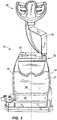
- the illustrated floor cleaning tool 10 is movable along a direction of travel parallel to the axis 26 shown in Fig. 3 , which is determined by the rolling direction of the illustrated wheels 28a, 28b. This direction of travel defines opposite lateral sides 14, 16 of the floor cleaning tool 10, as well as a front 18 and rear 20 of the tool 10.
- the floor cleaning tool 10 also includes a top 22 and bottom 24.
- the floor cleaning tool 10 can have a reservoir 30 for containing a cleaning product.
- the reservoir 30 can be located within the housing 12 of the floor cleaning tool 10, and can be one of any number of reservoirs 30 containing the same or different cleaning products that in some embodiments can be dispensed independently from one another, can be mixed prior to or as the cleaning products are discharged upon a surface to be cleaned, and/or can be discharged at different locations upon the surface to be cleaned.
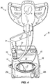
- the floor cleaning tool 10 includes one or more reservoirs 32 for containing used cleaning product (see Fig. 5 ).
- the used cleaning product can be drawn into the floor cleaning tool by vacuum force, and in some cases can pass through one or more filters to filter the cleaning product after use and/or to recycle the used cleaning product for reuse.
- the illustrated floor cleaning tool 10 includes a handle 34 having a proximal end 36 and a distal end 38.
- the proximal end 36 is coupled to a side 14 of the housing 12 (with reference to the direction of travel of the floor cleaning tool as described above).
- the attachment location of the proximal end 36 of the handle 34 is located completely to one lateral side of a central plane bisecting the floor cleaning tool 10 (i.e., into opposite lateral sides as described above).
- the axis 26 described above lies in this central plane.
- the handle 34 is coupled for rotation relative to the housing 12. This rotation can be about an axis 40 extending laterally with respect to the sides 14, 16 of the floor cleaning tool 10 (described above).
- the distal end 38 of the handle 34 extends away from the housing 12 to a location disposed a distance from the body 12 of the floor cleaning tool 10.
- the distal end 38 of the handle 34 is substantially aligned with (i.e., lies within) a plane bisecting the floor cleaning tool 10 into opposite lateral sides as described above.
- the handle 34 can be shaped to include an offset or "jogged" portion extending laterally at a location between the distal and proximal ends 36, 38.
- the floor cleaning tool 10 can include a lock 42 between the handle 34 and the remainder of the floor cleaning tool 10 (e.g., between the handle 34 and the housing 12) to releasably secure the handle 34 in different positions.
- the lock 42 can releasably secure the handle 34 in different rotational positions with respect to the housing 12.
- a first (deployed) position of the handle 34 in the illustrated embodiment is shown in Figs. 1-6
- a second (stowed) position of the handle 34 is shown in Fig. 7 .
- Any number of additional rotational positions of the handle 34 are possible, such as any number of positions intermediate and beyond those shown in Figs. 1-7 .
- a user can select a desired working position (e.g., height and angle) of the handle 34, and can lock the handle 34 in that position with the lock 42.
- a desired working position e.g., height and angle
- One such lock 42 is illustrated in Figs. 8-11 .
- the illustrated lock 42 includes a gear 44 having at least one tooth, such as the plurality of teeth 46 about the periphery of the gear 44 shown in Figs. 8-11 .
- the gear 44 shown in Figs. 8-11 is secured against rotation.
- the gear 44 can be defined by any feature of the floor cleaning tool 10, and can be a separate part attached to the floor cleaning tool or can be integral with or defined by any portion of the floor cleaning tool 10.
- the gear 44 can be defined by a set of teeth or apertures in the body, a frame, or other element of the floor cleaning tool 10.
- the lock 42 can also include one or more pawls movable to releasably engage the teeth 46 of the gear 44. At least one such pawl can be coupled to the handle 34 to selectively engage the gear 44, and can have one or more teeth or other protrusions shaped for this purpose. In the illustrated embodiment, two pawls 48 and 52 are coupled to the handle 34 for rotation about a pin 60, although any other manner of rotational movement is possible.
- the first pawl 48 of the illustrated embodiment includes first teeth 50 and a second pawl 52 includes second teeth 54 (see Figs. 9 and 10 ). Both sets of teeth 50, 54 are sized and shaped to releasably engage the teeth 46 of the gear 44.
- the teeth 50 of the first pawl 48 are circumferentially offset with respect to the teeth 54 of the second pawl 52. In this manner, at least one pawl 48, 52 can engage the gear 44 in a number of rotational positions of the handle 34 with respect to the body 12. In some embodiments, only one of the pawls 48, 52 is engaged with the gear 44 in any particular rotational position of the handle 34.
- the first teeth 50 and the second teeth 54 can have substantially an identical configuration, although different configurations of the teeth 50, 54 are possible. Also, although each tooth of a set of teeth on a pawl 48, 52 can be substantially identical, in some embodiments (e.g., the illustrated embodiment of Figs. 8-11 ), one or more of the first teeth 50 and the second teeth 54 can have a different shape than the others on the same pawl 48, 52. By using teeth 50, 54 of different shapes on the same pawl 48, 52, it is possible to enhance the ability of the pawls 48, 52 and gear 44 to resist movement of the handle 34 in both directions.
- a first end tooth of at least one of the first and second sets of teeth 50, 54 is shaped to resist rotation of the handle 34 in a clockwise direction
- a second end tooth of at least one of the first and second teeth 50, 54 is shaped to resist rotation of the handle 34 in a counterclockwise direction.
- One or more biasing members can be utilized to bias the first and second pawls 48, 52 (and therefore, the first and second sets of teeth 50 and 54) into engagement with the gear teeth 46.
- a first spring 56 is positioned to bias the first pawl 48 against the gear 44
- a second spring 58 is positioned to bias the second pawl 52 against the gear 44.
- the illustrated springs 56 and 58 are coil springs, but other biasing members can be utilized, such as leaf springs, torsion springs, elastomeric bands, blocks, or other elements, magnets and magnet sets, and the like.
- the floor cleaning tool 10 of the illustrated embodiment has two pawls 48, 52 for releasable engagement with a gear 44 as described above, it will be appreciated that a single pawl 48, 52 can instead be used, or that three or more pawls 48, 52 can be used, and can be offset as also described above for greater adjustability of the handle 34.
- the pawls 48, 52 of the lock 42 can be released by a user in order to permit the handle 34 to rotate to a desired position.
- a user-manipulatable actuator can be connected to the pawls 48, 52 in order to pull the pawls 48, 52 out of engagement with the gear 44.
- a flexible actuator such as the illustrated cable 62, is coupled to the first and second pawls 48 and 52.
- the cable 62 is also coupled to a user manipulable control (described in greater detail below). Actuation of the cable 62 pulls the first and second pawls 48, 52 out of engagement of the gear 44 and against the biasing force of the first and second springs 56 and 58.
- the springs 56 and 58 bias the respective pawl 48 and 52 back against the gear 44, such that at least one of the first teeth 50 and the second teeth 54 engage the gear teeth 46 to retain the handle 34 in a fixed rotational position with respect to the housing 12.
- the pawls 48, 52 are carried by the handle 34, and rotate to different positions upon rotation of the handle 34, whereas the gear 44 is stationary with respect to the rest of the floor cleaning tool 10.
- these elements of the lock 42 can be reversed in position while still performing the same or similar functions described above.
- the pawls 48, 52 can be carried adjacent the handle 34 and can still be connected to a user-manipulatable control on the handle 34, while the gear 44 can be carried by and movable with the handle 34 for adjustment thereof.
- the distal end 38 of the handle 34 of the floor cleaning tool 10 can be provided with one or more locations where a user can grip the handle 34, and one or more user-manipulatable controls by which functions of the floor cleaning tool 10 can be performed.
- the user manipulable control of the floor cleaning tool illustrated in Figs. 12-15 is presented by way of example, and includes a hand grip portion 64 positioned at the distal end 38 of the handle 34.
- the hand grip portion 64 can include a central horn 66 having first and second grips 68 and 70 extending therefrom to provide graspable portions for a user.
- the grips 68, 70 are generally cylindrical in shape, lie in a common plane, and converge together to define an obtuse angle therebetween (i.e., to create a generally chevron shape). Other grip shapes and orientations are possible.
- the illustrated hand grip portion 64 also includes a C- or U-shaped portion 72 extending from an end of the first grip 68, around the horn 66, and to an end of the second grip 70.
- the C-shaped portion 72 can be attached to and at least partially covers an outboard end of each grip 68, 70, and can be attached to the distal end 38 of the handle 34 in any suitable manner.
- the grips 68, 70, central horn 66, and C- or U-shaped portion 72 cooperate to define a first aperture 74 and a second aperture 76.
- the hand grip portion 64 can include any of a number of user-manipulatable controls connected to components of the floor cleaning tool 10 to control (for example) speed and direction of the floor cleaning tool 10 across a surface, dispense of a cleaning product by the floor cleaning tool 10, recovery of the cleaning product, movement of the pawls 48 and 52 to adjust the handle position (described in greater detail above), and the like.
- the illustrated hand grip portion 64 includes a first actuator 78 extending from the horn 66 into the first aperture 74, and a second actuator 80 extending from the horn 66 into the second aperture 76.
- the first and second actuators 78, 80 are operable to control at least one of dispensing and recovering a cleaning solution and releasable securing the handle 34.
- the illustrated hand grip portion 64 further includes a third actuator 82 extending from the first cylindrical portion 68 into the first aperture 74, and a fourth actuator 84 extending from the second cylindrical portion 70 into the second aperture 76.
- the third and fourth actuators 82 and 84 are operable to control at least one of speed and direction of movement of the floor cleaning tool 10.
- any of the actuators described above can perform multiple functions, such as to also provide a connection location for the cable 62 extending to the handle lock 42 described above (thereby generating retraction of the pawls 48 and 52 from engagement with the gear 44 when actuated).
- the actuators 78, 80, 82 and 84 illustrated in Figs. 12- 15 are positioned within the first and second apertures 74 and 76 to inhibit accidental actuation, although any other locations of the actuators on the hand grip portion 64 are possible. Also, the first and second apertures 74 and 76 shown in Figs. 12-15 are shaped and dimensioned to be graspable by a user, such that a user's fingers can extend through at least a portion of the first and second apertures 74 and 76.
- the floor cleaning tool 10 can support a number of different cleaning implements.
- the floor cleaning tool 10 supports a roller 86 coupled for rotation with respect to the housing 12 and positioned to engage a floor surface.
- the roller 86 can take any cleaning implement form desired, and in the illustrated embodiment is a brush roller.
- the roller 86 is positioned on the bottom 24 of the housing 12 near the front 18 of the housing 12, and extends along a roller axis 88, which can be substantially parallel to the handle axis 40 described above.
- the roller 86 can be coupled for rotation by a motor 90 or other suitable driving arrangement in any manner desired, such as by a belt and pulley or chain and sprocket connection, a direct drive connection, a geared connection, and the like.
- the roller 86 in the illustrated embodiment is supported for rotation by a bracket 92.
- the bracket 92 can have a spindle 94 extending therefrom and sized to support the roller 86 for rotation.
- the bracket 92 can have a socket within which a spindle of or connected to the roller 86 is rotatably received.
- the bracket 92 can include a first flange 96 extending into mating engagement with an aperture (e.g., a recess) in the housing 12.
- the illustrated first flange 96 extends in a substantially axial direction with respect to the axis of rotation 88 of the roller 86, and defines an aperture (e.g., slot 98 in Figs. 16-22 ) for receiving a fastener therethrough.
- a single fastener 100 is utilized to secure the bracket 92 to the housing 12, can be loosened or tightened by hand (i.e., without the use of tools), and can be threaded into and out of a threaded aperture in the housing 12 or other structural member of the floor cleaning tool 10.
- the bracket 92 can also include a second flange 102 and a third flange 104, either of both of which extend in a substantially axial direction with respect to the axis of rotation 88 of the roller 86 for mating engagement with respective apertures (e.g., recesses) in the front 18 of the housing 12. Any two or more of the flange engagements described above can cooperate to inhibit rotation of the bracket 92 with respect to the housing 12.
- the bracket 92 can also include one or more wall rollers 106 positioned to engage a wall surface and inhibit the floor cleaning tool 10 from scratching or otherwise damaging the wall surface.
- the roller 86 can be removed without the use of tools by rotating the single fastener 100 by hand, removing the bracket 92 from the housing 12, and laterally (axially) withdrawing the roller 86 from the housing 12. In some cases, removal of the bracket 92 from the housing 12 is sufficient to disengage the roller 86 from the housing 12, whereas in other embodiments, the roller 86 is moved laterally (axially) to cause such disengagement as well as to remove the roller 86. In some embodiments, the roller 86 is conveniently removable from the housing 12 in a purely lateral (axial) direction.
- the roller 86 can be cleaned and re-inserted, or can be replaced by a new and/or different roller suitable for a different floor cleaning operation.
- the roller 86 can be replaced in the illustrated embodiment without the use of tools inserting the roller 86 into the housing 12 in a purely lateral (axial) direction.
- the bracket 92 can then be positioned on the housing 12 such that the flanges 96, 102 and 104 matingly engage the housing 12.
- the fastener 100 can then be re-attached to the housing 12 to secure the bracket 92 to the housing 12.
- the fastener 100 can be tightened by hand, without the use of tools. In this manner, the bracket 92 can be positioned exterior to the housing 12 and exterior to the roller 86, and can be quickly and conveniently removed and replaced by hand by a user for access to the roller 86 inside.
- Some embodiments of the present invention include one or more lengths of conduit 108 fluidly coupled to the first reservoir 30 to direct fluid from the first reservoir 30 to one or more fluid chambers 110 (see single fluid chamber 110 in Fig. 19 , for example).
- the fluid chamber 110 can be defined by a recess 112 in the housing 12 and a cover plate 114 coupled to the housing 12, although any other combination of housing and additional components defining the fluid chamber 110 is possible, and falls within the spirit and scope of the present invention.
- the illustrated cover plate 114 includes a first inlet 116 and a second inlet 1 18 fluidly coupled to respective conduits 108 leading to the first reservoir 30, although any number of inlets and conduits 108 supplying liquid from the first reservoir are possible.
- the illustrated recess 112 of the fluid chamber 110 defines a plurality of apertures 120 that are aligned substantially along a line. In other embodiments, the plurality of apertures 120 can be arranged in any other manner desired, such as in a staggered fashion, in two or more rows of apertures 120, and the like.
- apertures 120 in the illustrated embodiment are substantially round, although any other shape or combination of aperture shapes having larger or smaller sizes can be used as desired, such as elongated apertures separated by the same, larger, or smaller distances, star-shaped apertures in any desired arrangement, and the like.
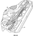
- a nozzle plate 122 can be positioned in the recess 112, and can be shaped to have a plurality of protrusions 124 that in some embodiments can substantially correspond to the shape and size of the plurality of apertures 120 described above. As shown in Figs. 19 , 23 and 24 , the plurality of protrusions 124 are each received in a respective aperture 120, and are thereby supported within the apertures 120. The protrusions 124 are shown in greater detail in Fig. 27 . With reference to Figs. 19 and 23-27 , the nozzle plate 122 includes a plurality of apertures 126, such that each aperture 126 is positioned in a respective protrusion 124.
- the apertures 126 can have a relatively large diameter adjacent the fluid chamber 110, and a relatively small diameter below the fluid chamber 110, or in other embodiments can have a substantially constant diameter through the nozzle plate 122.
- the size of the relatively small diameter portion of the apertures 126 in the illustrated embodiment can help to regulate the delivery of fluid onto the floor surface.
- the mating relationship between the apertured protrusions 124 of the nozzle plate 122 and the apertures 120 of the fluid chamber 110 performs the functions of registering the nozzle plate 122 in proper position within the fluid chamber 110 and providing support for the nozzle plate 122 in that position.
- these two functions can be performed in other manners, such as by receiving an apertured channel in the nozzle plate 122 within a mating open channel in the fluid chamber 110, by clamping peripheral edges of an apertured nozzle plate 122 between portions of the housing 12 at least partially defining the fluid chamber 110, and the like, any of which can utilize nozzle plates 122 having different shapes (e.g., with or without protrusions 124).
- the nozzle plate 122 is removable and replaceable within the fluid chamber 110.
- the nozzle plate 122 can be resiliently deformable, and can comprise an elastomeric or other flexible, resilient material such as rubber, neoprene, urethane, latex, and the like.
- the resiliently deformable nozzle plate 122 can be removed from the fluid chamber 110, cleaned, and replaced in the fluid chamber 110.
- the resiliently deformable nature of the nozzle plate 122 permits a user to deflect the nozzle plate 122 to ease cleaning operations, such as for removing scale, lime, and other mineral buildup on the nozzle plate 122.
- the cleaning tool 10 can include multiple nozzle plates 122, each of which has differently numbered, arranged, sized and/or shaped apertures. This permits a user to determine the desired type and volume of cleaning solution flowing from the fluid chamber 110 to a floor surface over a given period of time.
- a wiping blade 128 can be coupled to the front 18 of the housing 12 to strip fluid as the floor cleaning tool 10 is moved in a rearward direction. In some embodiments, the wiping blade 128 is movable to different heights (e.g., triggered by an actuator 80, described in greater detail below) to facilitate this function.
- Some embodiments of the present invention include one or more squeegees for assisting in floor cleaning operations.
- An example of such a squeegee is used in the squeegee assembly 140 illustrated in Figs. 28-32 .
- the squeegee assembly 140 can be positioned to engage the bottom 24 of the floor cleaning tool 10, and is positioned between the roller 86 and the first and second wheels 28a, 28b.
- the squeegee assembly 140 can be positioned to engage a floor surface during operation of the floor cleaning tool 10.
- the illustrated squeegee assembly 140 includes a first squeegee 142 and a second squeegee 144 spaced from the first squeegee 142, although a single squeegee or three or more squeegees can instead be used in other embodiments (e.g., side-by-side with respect to one another, each following another in movement of the floor cleaning tool across a surface, and the like).
- the first and second squeegees 142, 144 of the illustrated embodiment have a concave shape designed to direct cleaning solution to a center of the squeegee assembly 140.
- the first blade 142 can define a recess 146 to permit cleaning solution to enter a vacuum area between the first and second squeegees 142, 144.
- the illustrated squeegee assembly 140 further includes a plate 148 coupled to and retaining an upper portion of the first and second squeegees 142, 144.
- the illustrated plate 148 has an aperture 150 therein, which in some embodiments can be generally aligned with the recess 146, but which in any case can be used as a location through which a vacuum is drawn from the area defined between the squeegees 142, 144, the plate 148, and the floor surface. Any number of vacuum apertures 150 can be used for this purpose.
- a length of conduit (not shown) can be coupled to each such aperture 150 and to the second reservoir 32 to permit recovery of cleaning product from the floor surface.
- the illustrated squeegee assembly 140 also includes first, second and third vertical guide wheels 152a, 152b, 152c that can orient the squeegee assembly 140 at a desired height and angle with respect to the ground surface, although any other number and location of such wheels is possible in other embodiments.
- the squeegee assembly 140 can also include any number of horizontal guide wheels 154a, 154b that can roll when in contact with a surface (such as a wall).
- the squeegee assembly 140 further includes at least one fastener operable to removably couple the squeegee assembly 140 to the floor cleaning tool 10.
- the squeegee assembly 140 includes first and second protrusions 156, 158 on opposite sides of the squeegee assembly 140.
- a squeegee assembly mount 160 can be provided beneath the floor cleaning tool 10, and can be coupled to the housing 12, a frame of the tool 10, or any other structural member of the tool 10 in order to suspend or otherwise support the squeegee assembly 140 on the tool 10 when connected thereto.
- the 28-32 has first and second apertures 162, 164 on opposite sides of the squeegee assembly mount 160 (i.e., on the first side 14 of the tool 10, and on the second side 16 of the tool 10, respectively).
- the first aperture 162 is sized and shaped to receive the first protrusion 156 when the first protrusion 156 is in a first orientation, and is sized and shaped to retain the first protrusion 156 when the first protrusion 156 is in a second orientation.
- the second aperture 164 is sized and shaped to receive the second protrusion 158 when the second protrusion 158 is in a first orientation, and sized and shaped to retain the second protrusion 158 when the second protrusion 158 is in a second orientation.
- the first orientation is rotated about 90 degrees from the second orientation.
- the apertures 162, 164 and the protrusions 156, 158 are generally diamond-shaped, and the apertures 162, 164 are closed (i.e., not open to an edge of the squeegee assembly mount 160).
- other aperture and protrusion numbers, shapes, sizes, and locations can be utilized to selectively couple the squeegee assembly 140 to the floor cleaning tool 10.
- the squeegee assembly mount 160 can include one or more detents or protrusions to retain the protrusions 156, 158 in their first and/or second orientations.
- two projections 166, 168 are positioned on the squeegee assembly mount 160 to retain the first and second protrusions 156, 158 in their respective second orientations.
- the squeegee assembly 140 can be removed without the use of tools by rotating the protrusions 156, 158 from their respective second orientations to their respective first orientations, and then lowering the squeegee assembly 140 to draw the protrusions 156, 158 through and out of their respective apertures 162, 164 in the squeegee assembly mount 160.
- the squeegee assembly 140 can then be laterally removed from the floor cleaning tool 10 either at the first side 14 or at the second side 16 of the floor cleaning tool. Accordingly, the squeegee assembly 140 can be removed in a vertical, then horizontal and lateral direction from between the roller 86 and the wheels 28a, 28b of the floor cleaning tool 10 without lifting or tilting the floor cleaning tool 10.
- the squeegee assembly 140 can then be cleaned, serviced, repaired (for example, by replacement of one or more of the blades 142, 144) or exchanged, and then the new or repaired squeegee assembly 140 can be inserted.
- the squeegee assembly 140 can be coupled to the housing 12 without the use of tools by laterally inserting the squeegee 140 into the housing 12 in a lateral direction between the roller 86 and the wheels 28a, 28b of the floor cleaning tool 10.
- the squeegee assembly 140 can then be raised in a vertical direction to insert the protrusions 156, 158 into their respective apertures 162, 164 in the squeegee assembly mount 160.
- the protrusions 156, 158 are then rotated from their respective first orientations to their respective second orientations.
- the projections 166, 168 can retain the respective protrusions 156, 158 in their second orientations to retain the squeegee assembly 140 mounted on the floor cleaning tool 10. It should also be noted that the protrusions 156, 158 can be rotated by hand (i.e., without the use of tools).
Landscapes
- Engineering & Computer Science (AREA)
- Mechanical Engineering (AREA)
- Cleaning Implements For Floors, Carpets, Furniture, Walls, And The Like (AREA)
- Road Repair (AREA)
Abstract
Description
- Numerous powered floor cleaning tools exist in the marketplace, each of which attempt to address a large number of characteristics that are commonly desired by users. For example, in some cases, a floor cleaning tool that can be placed in a compact state to take up minimum storage space is of high importance. As another example, a floor cleaning tool easily adapted to different users (e.g., user height, arm length, and the like) is needed. Still other examples of desired floor cleaning tool characteristics include floor cleaning tool handles and controls that are easy to use and intuitive, and floor cleaning tools that are easy to service and replace (such as for removal, service, and replacement of floor cleaning tool brushes, cleaning and maintenance of internal parts of the floor cleaning tool, and removal and replacement of squeegee blades and other parts.
- Unfortunately, despite the advanced age of powered floor cleaning tool technology, significant advancements in each of these features has been slow or non-existent. Nevertheless, based upon the value such advancements provide for users and servicers of powered floor cleaners, new and improved powered floor cleaners continue to be welcome in the industry.
- Some embodiments of the present invention provide a floor cleaning tool, comprising: a housing; a reservoir coupled to the housing and adapted to hold a cleaning solution; at least one wheel by which the floor cleaning tool moves across a floor surface in a direction of travel, the direction of travel at least partially defining a front, rear, and lateral sides of the floor cleaning tool; and a handle including a proximal end and a distal end, the handle pivotable about an axis extending laterally with respect to the direction of travel of the floor cleaning tool.
- In some embodiments, a floor cleaning tool is provided, and comprises: a housing; a roller rotatable with respect to the housing about an axis extending in an axial direction; a bracket having a first portion extending in the axial direction of the roller and shaped to releasably and matingly engage the housing; and a second portion extending in the axial direction of the roller and shaped to releasably and matingly engage an end of the roller, the roller rotatable with respect to the second portion of the bracket; and a fastener engaged with the first portion of the bracket, the bracket releasably and removably coupled to the roller and to the housing via the fastener.
- Some embodiments of the present invention provide a method for coupling a roller to a floor cleaning tool, the roller having an axis of rotation extending in an axial direction, the method comprising: laterally inserting the roller onto the floor cleaning tool; coupling an end of the roller to the floor cleaning tool by mating a spindle within a receptacle; coupling a bracket to an end of the roller; engaging a portion of the bracket extending in the axial direction with the floor cleaning tool; engaging the portion of the bracket with a fastener to secure the bracket to the floor cleaning tool; supporting the roller for rotation with respect to the floor cleaning tool via the spindle in the receptacle; and resisting rotation of the bracket with respect to the floor cleaning tool via engagement of the portion of the bracket with the floor cleaning tool.
- In some embodiments, a floor cleaning tool is provided, and comprises: a housing; a reservoir coupled to the housing and shaped to contain a cleaning solution; a resiliently deformable plate coupled to the housing and defining a plurality of apertures; and a conduit extending from the reservoir to the plate and establishing fluid communication between the reservoir and the plate for delivery of cleaning solution from the reservoir, through the conduit, and through the plurality of apertures in the resiliently deformable plate; the resiliently deformable plate removable from the conduit and the housing for cleaning and replacement.
- Some embodiments of the present invention provide a floor cleaning tool comprising: a housing; a reservoir coupled to the housing and adapted to hold a cleaning solution; a floor-engaging roller coupled to the housing and rotatable with respect to the housing; a wheel by which the floor cleaning tool moves across a floor surface in a direction of travel, the direction of travel at least partially defining a front, rear, and lateral sides of the floor cleaning tool; a squeegee laterally insertable between the roller and the wheel; and a squeegee mount located between the roller and the wheel by which the squeegee is releasably mounted to the floor cleaning tool.
- In some embodiments, a method of installing a squeegee assembly on a floor cleaning tool adapted to move in a direction of travel defining a front, rear, and lateral sides of the floor cleaning tool is provided, and comprises: laterally inserting the squeegee assembly below the floor cleaning tool; raising the squeegee assembly to insert a projection of the squeegee assembly into a mating aperture of the floor cleaning tool; and rotating the projection to releasably couple the squeegee assembly to the floor cleaning tool
- Some embodiments of the present invention provide a floor cleaning tool comprising: a housing; a handle rotatably coupled to the housing; a user-manipulatable control; and a lock coupled to the user-manipulatable control, the lock movable from a locked state to an unlocked state by actuation of the user-manipulatable control, the lock maintaining the handle in one of a plurality of rotational positions with respect to the housing when in the locked state, releasable to permit the handle to be moved to another of the plurality of rotational positions with respect to the housing, and movable to the locked state again to maintain the handle in the other of the plurality of rotational positions.
- Other aspects of the invention will become apparent by consideration of the detailed description and accompanying drawings.
- Fig. 1
- is a left side view of a floor cleaning tool;
- Fig. 2
- is a perspective view of the floor cleaning tool of
Fig. 1 ; - Fig. 3
- is a front view of the floor cleaning tool of
Figs. 1 and 2 ; - Fig. 4
- is a rear view of the floor cleaning tool of
Figs. 1-3 ; - Fig. 5
- is a right side perspective view of the floor cleaning tool of
Figs. 1-4 , shown with a handle in a first position; - Fig. 6
- is a left side perspective view of the floor cleaning tool of
Figs. 1-5 , shown with the handle in the position ofFig. 5 ; - Fig. 7
- is a left side perspective view of the floor cleaning tool of
Figs. 1-6 , shown with the handle in a second position; - Fig. 8
- is a cross-sectional view of a locking mechanism for the handle of the floor cleaning tool of
Figs. 1-7 ; - Fig. 9
- is a perspective cross-sectional view of the locking mechanism of
Fig. 8 ; - Fig. 10
- is a detail perspective cross-sectional view of the locking mechanism of
Figs. 8 and9 ; - Fig. 11
- is a detail cross-sectional view of the locking mechanism of
Figs. 8-10 ; - Fig. 12
- is a front view of a distal end of the floor cleaning tool handle shown in
Figs. 1-7 ; - Fig. 13
- is a perspective view of the distal end of the handle shown in
Fig. 12 ; - Fig. 14
- is a side view of the distal end of the handle shown in
Figs. 12 and 13 ; - Fig. 15
- is a top view of the distal end of the handle shown in
Figs. 12-14 ; - Fig. 16
- is a perspective view of a front portion of the floor cleaning tool of
Figs. 1-15 , shown with a cover removed; - Fig. 17
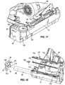
- is a perspective view of the front portion of the floor cleaning tool of
Figs. 1-16 , shown with two covers removed; - Fig. 18
- is a partially exploded view of a front portion of the floor cleaning tool shown in
Figs. 1-17 ; - Fig. 19
- is a cross-sectional view of a front portion of the floor cleaning tool shown in
Figs. 1-18 ; - Fig. 20
- is a partially exploded perspective detail view of a front portion of the floor cleaning tool shown in
Figs. 1-19 ; - Fig. 21
- is another partially exploded detail view of a front portion of the floor cleaning tool shown hi
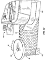
Figs. 1-20 ; - Fig. 22
- is a partially exploded detail view of a front portion of the floor cleaning tool shown in
Figs. 1-21 ; - Fig. 23
- is a partially exploded perspective detail view of a front portion of the floor cleaning tool shown in
Figs. 1-22 , shown with a nozzle plate partially installed. - Fig. 24
- is another partially exploded perspective detail view of the front portion of the floor cleaning tool shown in
Fig. 23 ; - Fig. 25
- is another partially exploded perspective detail view of the front portion of the floor cleaning tool shown in
Figs. 22 and23 , shown with the nozzle plate fully installed; - Fig. 26
- is a top perspective detail view of the nozzle plate of the floor cleaning tool shown in
Figs. 1-25 ; - Fig. 27
- is a bottom perspective detail view of the nozzle plate of the floor cleaning tool shown in
Figs. 1-26 ; - Fig. 28
- is a partially exploded perspective view of the floor cleaning tool shown in
Figs. 1-27 , shown with a squeegee assembly prior to installation; - Fig. 29
- is a perspective detail view of the squeegee assembly and floor cleaning tool shown in
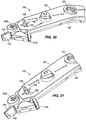
Figs. 1-28 ; - Fig. 30
- is a perspective detail view of the squeegee assembly of the floor cleaning tool shown in
Figs. 1-29 , shown installed on a floor cleaning tool mount; - Fig. 31
- is another perspective detail view of the squeegee assembly of the floor cleaning tool shown in
Figs. 1-30 , shown installed on a floor cleaning tool mount, and - Fig. 32
- is another perspective detail view of the squeegee assembly of the floor cleaning tool shown in
Figs. 1-31 , shown installed on a floor cleaning tool mount. -
Figs. 1-7 illustrate afloor cleaning tool 10 according to an embodiment of the present invention. The illustratedfloor cleaning tool 10 includes ahousing 12, first andsecond wheels housing 12 for movement across a surface, afirst reservoir 30 for containing a cleaning product in any form (e.g., fluid, powder, and the like), and aroller 86 for performing a cleaning operation upon the surface. Thefloor cleaning tool 10 described and illustrated herein has twowheels floor cleaning tool 10. Thewheels floor cleaning tool 10 are powered by a motor (not shown). However, in other embodiments, any or all of the wheels of thefloor cleaning tool 10 can be non-powered. Also, thewheels wheels - Although the
floor cleaning tool 10 described and illustrated in the accompanying drawings includeswheels floor cleaning tool 10 over a surface, it will be appreciated that other types of devices can be used to move thefloor cleaning tool 10, including without limitation powered or un-powered tracks. For the sake of simplicity, the term "wheel" as used herein and in the appended claims refers to all such moving elements. - The
floor cleaning tool 10 is movable along a direction determined at least in part by the orientation of thewheels floor cleaning tool 10 is movable along a direction of travel parallel to theaxis 26 shown inFig. 3 , which is determined by the rolling direction of the illustratedwheels lateral sides floor cleaning tool 10, as well as a front 18 and rear 20 of thetool 10. Thefloor cleaning tool 10 also includes a top 22 and bottom 24. - As mentioned above, the
floor cleaning tool 10 can have areservoir 30 for containing a cleaning product. Thereservoir 30 can be located within thehousing 12 of thefloor cleaning tool 10, and can be one of any number ofreservoirs 30 containing the same or different cleaning products that in some embodiments can be dispensed independently from one another, can be mixed prior to or as the cleaning products are discharged upon a surface to be cleaned, and/or can be discharged at different locations upon the surface to be cleaned. - In some embodiments, the
floor cleaning tool 10 includes one ormore reservoirs 32 for containing used cleaning product (seeFig. 5 ). The used cleaning product can be drawn into the floor cleaning tool by vacuum force, and in some cases can pass through one or more filters to filter the cleaning product after use and/or to recycle the used cleaning product for reuse. - As shown in
Figs. 1-7 , the illustratedfloor cleaning tool 10 includes ahandle 34 having aproximal end 36 and adistal end 38. Theproximal end 36 is coupled to aside 14 of the housing 12 (with reference to the direction of travel of the floor cleaning tool as described above). In other words, the attachment location of theproximal end 36 of thehandle 34 is located completely to one lateral side of a central plane bisecting the floor cleaning tool 10 (i.e., into opposite lateral sides as described above). In the illustrated embodiment ofFigs. 1-7 , theaxis 26 described above lies in this central plane. - In some embodiments, the
handle 34 is coupled for rotation relative to thehousing 12. This rotation can be about anaxis 40 extending laterally with respect to thesides distal end 38 of thehandle 34 extends away from thehousing 12 to a location disposed a distance from thebody 12 of thefloor cleaning tool 10. In the illustrated embodiment ofFigs. 1-7 , thedistal end 38 of thehandle 34 is substantially aligned with (i.e., lies within) a plane bisecting thefloor cleaning tool 10 into opposite lateral sides as described above. To connect a centrally-aligneddistal end 38 and a laterally-disposedproximal end 36 of thehandle 34, thehandle 34 can be shaped to include an offset or "jogged" portion extending laterally at a location between the distal and proximal ends 36, 38. - The
floor cleaning tool 10 can include alock 42 between thehandle 34 and the remainder of the floor cleaning tool 10 (e.g., between thehandle 34 and the housing 12) to releasably secure thehandle 34 in different positions. In those embodiments in which thehandle 34 is rotatable with respect to thehousing 12, thelock 42 can releasably secure thehandle 34 in different rotational positions with respect to thehousing 12. By way of example, a first (deployed) position of thehandle 34 in the illustrated embodiment is shown inFigs. 1-6 , whereas a second (stowed) position of thehandle 34 is shown inFig. 7 . Any number of additional rotational positions of thehandle 34 are possible, such as any number of positions intermediate and beyond those shown inFigs. 1-7 . - By virtue of the rotatability of the
handle 34 and the lock 42 (described in greater detail below), a user can select a desired working position (e.g., height and angle) of thehandle 34, and can lock thehandle 34 in that position with thelock 42. Onesuch lock 42 is illustrated inFigs. 8-11 . The illustratedlock 42 includes agear 44 having at least one tooth, such as the plurality ofteeth 46 about the periphery of thegear 44 shown inFigs. 8-11 . Thegear 44 shown inFigs. 8-11 is secured against rotation. Although thegear 44 shown inFigs. 8-11 is round, and is shown as a discrete element secured to thebody 12 of thefloor cleaning tool 10, it will be appreciated that thegear 44 can be defined by any feature of thefloor cleaning tool 10, and can be a separate part attached to the floor cleaning tool or can be integral with or defined by any portion of thefloor cleaning tool 10. For example, thegear 44 can be defined by a set of teeth or apertures in the body, a frame, or other element of thefloor cleaning tool 10. - The
lock 42 can also include one or more pawls movable to releasably engage theteeth 46 of thegear 44. At least one such pawl can be coupled to thehandle 34 to selectively engage thegear 44, and can have one or more teeth or other protrusions shaped for this purpose. In the illustrated embodiment, twopawls handle 34 for rotation about apin 60, although any other manner of rotational movement is possible. Thefirst pawl 48 of the illustrated embodiment includesfirst teeth 50 and asecond pawl 52 includes second teeth 54 (seeFigs. 9 and 10 ). Both sets ofteeth teeth 46 of thegear 44. In the illustrated embodiment, theteeth 50 of thefirst pawl 48 are circumferentially offset with respect to theteeth 54 of thesecond pawl 52. In this manner, at least onepawl gear 44 in a number of rotational positions of thehandle 34 with respect to thebody 12. In some embodiments, only one of thepawls gear 44 in any particular rotational position of thehandle 34. - By providing the circumferentially offset relationship of the
teeth 50 of onepawl 48 with respect to theteeth 54 of anotherpawl 52 in thelock 42, more locked rotational positions of thehandle 34 are possible without requiring the use ofsmaller teeth durable lock 42. The offset relationship betweenteeth different pawls second pawls pawl pawls - In some embodiments, the
first teeth 50 and thesecond teeth 54 can have substantially an identical configuration, although different configurations of theteeth pawl Figs. 8-11 ), one or more of thefirst teeth 50 and thesecond teeth 54 can have a different shape than the others on thesame pawl teeth same pawl pawls gear 44 to resist movement of thehandle 34 in both directions. For example, in the illustrated embodiment, a first end tooth of at least one of the first and second sets ofteeth handle 34 in a clockwise direction, whereas a second end tooth of at least one of the first andsecond teeth handle 34 in a counterclockwise direction. - One or more biasing members can be utilized to bias the first and
second pawls 48, 52 (and therefore, the first and second sets ofteeth 50 and 54) into engagement with thegear teeth 46. In the illustrated embodiment, afirst spring 56 is positioned to bias thefirst pawl 48 against thegear 44, and asecond spring 58 is positioned to bias thesecond pawl 52 against thegear 44. The illustrated springs 56 and 58 are coil springs, but other biasing members can be utilized, such as leaf springs, torsion springs, elastomeric bands, blocks, or other elements, magnets and magnet sets, and the like. - Although the
floor cleaning tool 10 of the illustrated embodiment has twopawls gear 44 as described above, it will be appreciated that asingle pawl more pawls handle 34. - The
pawls lock 42 can be released by a user in order to permit thehandle 34 to rotate to a desired position. To this end, a user-manipulatable actuator can be connected to thepawls pawls gear 44. In the illustrated embodiment, for example, a flexible actuator, such as the illustratedcable 62, is coupled to the first andsecond pawls cable 62 is also coupled to a user manipulable control (described in greater detail below). Actuation of thecable 62 pulls the first andsecond pawls gear 44 and against the biasing force of the first andsecond springs springs respective pawl gear 44, such that at least one of thefirst teeth 50 and thesecond teeth 54 engage thegear teeth 46 to retain thehandle 34 in a fixed rotational position with respect to thehousing 12. - In the illustrated embodiment, the
pawls handle 34, and rotate to different positions upon rotation of thehandle 34, whereas thegear 44 is stationary with respect to the rest of thefloor cleaning tool 10. However, in other embodiments, these elements of thelock 42 can be reversed in position while still performing the same or similar functions described above. In particular, thepawls handle 34 and can still be connected to a user-manipulatable control on thehandle 34, while thegear 44 can be carried by and movable with thehandle 34 for adjustment thereof. - As shown in the illustrated embodiment of the present invention, the
distal end 38 of thehandle 34 of thefloor cleaning tool 10 can be provided with one or more locations where a user can grip thehandle 34, and one or more user-manipulatable controls by which functions of thefloor cleaning tool 10 can be performed. The user manipulable control of the floor cleaning tool illustrated inFigs. 12-15 is presented by way of example, and includes ahand grip portion 64 positioned at thedistal end 38 of thehandle 34. Thehand grip portion 64 can include acentral horn 66 having first andsecond grips grips hand grip portion 64 also includes a C- orU-shaped portion 72 extending from an end of thefirst grip 68, around thehorn 66, and to an end of thesecond grip 70. The C-shapedportion 72 can be attached to and at least partially covers an outboard end of eachgrip distal end 38 of thehandle 34 in any suitable manner. Thegrips central horn 66, and C- orU-shaped portion 72 cooperate to define afirst aperture 74 and asecond aperture 76. - The
hand grip portion 64 can include any of a number of user-manipulatable controls connected to components of thefloor cleaning tool 10 to control (for example) speed and direction of thefloor cleaning tool 10 across a surface, dispense of a cleaning product by thefloor cleaning tool 10, recovery of the cleaning product, movement of thepawls - The illustrated
hand grip portion 64 includes afirst actuator 78 extending from thehorn 66 into thefirst aperture 74, and asecond actuator 80 extending from thehorn 66 into thesecond aperture 76. In some embodiments, the first andsecond actuators handle 34. The illustratedhand grip portion 64 further includes athird actuator 82 extending from the firstcylindrical portion 68 into thefirst aperture 74, and afourth actuator 84 extending from the secondcylindrical portion 70 into thesecond aperture 76. In some embodiments, the third andfourth actuators floor cleaning tool 10. Further actuators can be provided on thehorn 66, as desired. Also, any of the actuators described above can perform multiple functions, such as to also provide a connection location for thecable 62 extending to thehandle lock 42 described above (thereby generating retraction of thepawls gear 44 when actuated). - The
actuators Figs. 12- 15 are positioned within the first andsecond apertures hand grip portion 64 are possible. Also, the first andsecond apertures Figs. 12-15 are shaped and dimensioned to be graspable by a user, such that a user's fingers can extend through at least a portion of the first andsecond apertures - The
floor cleaning tool 10 can support a number of different cleaning implements. In the embodiment illustrated inFigs. 16-22 , thefloor cleaning tool 10 supports aroller 86 coupled for rotation with respect to thehousing 12 and positioned to engage a floor surface. Theroller 86 can take any cleaning implement form desired, and in the illustrated embodiment is a brush roller. Theroller 86 is positioned on the bottom 24 of thehousing 12 near thefront 18 of thehousing 12, and extends along aroller axis 88, which can be substantially parallel to thehandle axis 40 described above. Theroller 86 can be coupled for rotation by amotor 90 or other suitable driving arrangement in any manner desired, such as by a belt and pulley or chain and sprocket connection, a direct drive connection, a geared connection, and the like. - The
roller 86 in the illustrated embodiment is supported for rotation by abracket 92. Thebracket 92 can have aspindle 94 extending therefrom and sized to support theroller 86 for rotation. Alternatively, thebracket 92 can have a socket within which a spindle of or connected to theroller 86 is rotatably received. Thebracket 92 can include afirst flange 96 extending into mating engagement with an aperture (e.g., a recess) in thehousing 12. The illustratedfirst flange 96 extends in a substantially axial direction with respect to the axis ofrotation 88 of theroller 86, and defines an aperture (e.g.,slot 98 inFigs. 16-22 ) for receiving a fastener therethrough. In the illustrated embodiment, asingle fastener 100 is utilized to secure thebracket 92 to thehousing 12, can be loosened or tightened by hand (i.e., without the use of tools), and can be threaded into and out of a threaded aperture in thehousing 12 or other structural member of thefloor cleaning tool 10. Thebracket 92 can also include asecond flange 102 and athird flange 104, either of both of which extend in a substantially axial direction with respect to the axis ofrotation 88 of theroller 86 for mating engagement with respective apertures (e.g., recesses) in thefront 18 of thehousing 12. Any two or more of the flange engagements described above can cooperate to inhibit rotation of thebracket 92 with respect to thehousing 12. - It will be appreciated that other sizes, shapes, quantities and locations of
flanges housing 12 or other structural member of the floor cleaning tool 10) are possible and are considered to be within the scope of the present invention. Thebracket 92 can also include one ormore wall rollers 106 positioned to engage a wall surface and inhibit thefloor cleaning tool 10 from scratching or otherwise damaging the wall surface. - With continued reference to the floor cleaning tool embodiment illustrated in
Figs. 16-22 , theroller 86 can be removed without the use of tools by rotating thesingle fastener 100 by hand, removing thebracket 92 from thehousing 12, and laterally (axially) withdrawing theroller 86 from thehousing 12. In some cases, removal of thebracket 92 from thehousing 12 is sufficient to disengage theroller 86 from thehousing 12, whereas in other embodiments, theroller 86 is moved laterally (axially) to cause such disengagement as well as to remove theroller 86. In some embodiments, theroller 86 is conveniently removable from thehousing 12 in a purely lateral (axial) direction. Theroller 86 can be cleaned and re-inserted, or can be replaced by a new and/or different roller suitable for a different floor cleaning operation. Theroller 86 can be replaced in the illustrated embodiment without the use of tools inserting theroller 86 into thehousing 12 in a purely lateral (axial) direction. Thebracket 92 can then be positioned on thehousing 12 such that theflanges housing 12. Thefastener 100 can then be re-attached to thehousing 12 to secure thebracket 92 to thehousing 12. Thefastener 100 can be tightened by hand, without the use of tools. In this manner, thebracket 92 can be positioned exterior to thehousing 12 and exterior to theroller 86, and can be quickly and conveniently removed and replaced by hand by a user for access to theroller 86 inside. - Some embodiments of the present invention include one or more lengths of
conduit 108 fluidly coupled to thefirst reservoir 30 to direct fluid from thefirst reservoir 30 to one or more fluid chambers 110 (see singlefluid chamber 110 inFig. 19 , for example). Thefluid chamber 110 can be defined by arecess 112 in thehousing 12 and acover plate 114 coupled to thehousing 12, although any other combination of housing and additional components defining thefluid chamber 110 is possible, and falls within the spirit and scope of the present invention. - The illustrated
cover plate 114 includes afirst inlet 116 and a second inlet 1 18 fluidly coupled torespective conduits 108 leading to thefirst reservoir 30, although any number of inlets andconduits 108 supplying liquid from the first reservoir are possible. The illustratedrecess 112 of thefluid chamber 110 defines a plurality ofapertures 120 that are aligned substantially along a line. In other embodiments, the plurality ofapertures 120 can be arranged in any other manner desired, such as in a staggered fashion, in two or more rows ofapertures 120, and the like. Also, theapertures 120 in the illustrated embodiment are substantially round, although any other shape or combination of aperture shapes having larger or smaller sizes can be used as desired, such as elongated apertures separated by the same, larger, or smaller distances, star-shaped apertures in any desired arrangement, and the like. - A
nozzle plate 122 can be positioned in therecess 112, and can be shaped to have a plurality ofprotrusions 124 that in some embodiments can substantially correspond to the shape and size of the plurality ofapertures 120 described above. As shown inFigs. 19 ,23 and24 , the plurality ofprotrusions 124 are each received in arespective aperture 120, and are thereby supported within theapertures 120. Theprotrusions 124 are shown in greater detail inFig. 27 . With reference toFigs. 19 and23-27 , thenozzle plate 122 includes a plurality ofapertures 126, such that eachaperture 126 is positioned in arespective protrusion 124. Theapertures 126 can have a relatively large diameter adjacent thefluid chamber 110, and a relatively small diameter below thefluid chamber 110, or in other embodiments can have a substantially constant diameter through thenozzle plate 122. The size of the relatively small diameter portion of theapertures 126 in the illustrated embodiment can help to regulate the delivery of fluid onto the floor surface. - The mating relationship between the
apertured protrusions 124 of thenozzle plate 122 and theapertures 120 of thefluid chamber 110 performs the functions of registering thenozzle plate 122 in proper position within thefluid chamber 110 and providing support for thenozzle plate 122 in that position. However, it will be appreciated that these two functions can be performed in other manners, such as by receiving an apertured channel in thenozzle plate 122 within a mating open channel in thefluid chamber 110, by clamping peripheral edges of anapertured nozzle plate 122 between portions of thehousing 12 at least partially defining thefluid chamber 110, and the like, any of which can utilizenozzle plates 122 having different shapes (e.g., with or without protrusions 124). - In some embodiments, the
nozzle plate 122 is removable and replaceable within thefluid chamber 110. Thenozzle plate 122 can be resiliently deformable, and can comprise an elastomeric or other flexible, resilient material such as rubber, neoprene, urethane, latex, and the like. The resilientlydeformable nozzle plate 122 can be removed from thefluid chamber 110, cleaned, and replaced in thefluid chamber 110. The resiliently deformable nature of thenozzle plate 122 permits a user to deflect thenozzle plate 122 to ease cleaning operations, such as for removing scale, lime, and other mineral buildup on thenozzle plate 122. In some embodiments, thecleaning tool 10 can includemultiple nozzle plates 122, each of which has differently numbered, arranged, sized and/or shaped apertures. This permits a user to determine the desired type and volume of cleaning solution flowing from thefluid chamber 110 to a floor surface over a given period of time. Also, awiping blade 128 can be coupled to thefront 18 of thehousing 12 to strip fluid as thefloor cleaning tool 10 is moved in a rearward direction. In some embodiments, thewiping blade 128 is movable to different heights (e.g., triggered by anactuator 80, described in greater detail below) to facilitate this function. - Some embodiments of the present invention include one or more squeegees for assisting in floor cleaning operations. An example of such a squeegee is used in the
squeegee assembly 140 illustrated inFigs. 28-32 . Thesqueegee assembly 140 can be positioned to engage the bottom 24 of thefloor cleaning tool 10, and is positioned between theroller 86 and the first andsecond wheels squeegee assembly 140 can be positioned to engage a floor surface during operation of thefloor cleaning tool 10. The illustratedsqueegee assembly 140 includes afirst squeegee 142 and asecond squeegee 144 spaced from thefirst squeegee 142, although a single squeegee or three or more squeegees can instead be used in other embodiments (e.g., side-by-side with respect to one another, each following another in movement of the floor cleaning tool across a surface, and the like). The first andsecond squeegees squeegee assembly 140. Also, thefirst blade 142 can define arecess 146 to permit cleaning solution to enter a vacuum area between the first andsecond squeegees - The illustrated
squeegee assembly 140 further includes aplate 148 coupled to and retaining an upper portion of the first andsecond squeegees plate 148 has anaperture 150 therein, which in some embodiments can be generally aligned with therecess 146, but which in any case can be used as a location through which a vacuum is drawn from the area defined between thesqueegees plate 148, and the floor surface. Any number ofvacuum apertures 150 can be used for this purpose. A length of conduit (not shown) can be coupled to eachsuch aperture 150 and to thesecond reservoir 32 to permit recovery of cleaning product from the floor surface. - The illustrated
squeegee assembly 140 also includes first, second and thirdvertical guide wheels squeegee assembly 140 at a desired height and angle with respect to the ground surface, although any other number and location of such wheels is possible in other embodiments. Thesqueegee assembly 140 can also include any number ofhorizontal guide wheels - The
squeegee assembly 140 further includes at least one fastener operable to removably couple thesqueegee assembly 140 to thefloor cleaning tool 10. In the illustrated embodiment, thesqueegee assembly 140 includes first andsecond protrusions squeegee assembly 140. Asqueegee assembly mount 160 can be provided beneath thefloor cleaning tool 10, and can be coupled to thehousing 12, a frame of thetool 10, or any other structural member of thetool 10 in order to suspend or otherwise support thesqueegee assembly 140 on thetool 10 when connected thereto. Thesqueegee assembly mount 160 illustrated inFigs. 28-32 has first andsecond apertures first side 14 of thetool 10, and on thesecond side 16 of thetool 10, respectively). Thefirst aperture 162 is sized and shaped to receive thefirst protrusion 156 when thefirst protrusion 156 is in a first orientation, and is sized and shaped to retain thefirst protrusion 156 when thefirst protrusion 156 is in a second orientation. Similarly, thesecond aperture 164 is sized and shaped to receive thesecond protrusion 158 when thesecond protrusion 158 is in a first orientation, and sized and shaped to retain thesecond protrusion 158 when thesecond protrusion 158 is in a second orientation. In some embodiments, the first orientation is rotated about 90 degrees from the second orientation. In the illustrated embodiment, theapertures protrusions apertures squeegee assembly 140 to thefloor cleaning tool 10. - The
squeegee assembly mount 160 can include one or more detents or protrusions to retain theprotrusions projections squeegee assembly mount 160 to retain the first andsecond protrusions - In some embodiments, the
squeegee assembly 140 can be removed without the use of tools by rotating theprotrusions squeegee assembly 140 to draw theprotrusions respective apertures squeegee assembly mount 160. Thesqueegee assembly 140 can then be laterally removed from thefloor cleaning tool 10 either at thefirst side 14 or at thesecond side 16 of the floor cleaning tool. Accordingly, thesqueegee assembly 140 can be removed in a vertical, then horizontal and lateral direction from between theroller 86 and thewheels floor cleaning tool 10 without lifting or tilting thefloor cleaning tool 10. Thesqueegee assembly 140 can then be cleaned, serviced, repaired (for example, by replacement of one or more of theblades 142, 144) or exchanged, and then the new or repairedsqueegee assembly 140 can be inserted. Thesqueegee assembly 140 can be coupled to thehousing 12 without the use of tools by laterally inserting thesqueegee 140 into thehousing 12 in a lateral direction between theroller 86 and thewheels floor cleaning tool 10. Thesqueegee assembly 140 can then be raised in a vertical direction to insert theprotrusions respective apertures squeegee assembly mount 160. Theprotrusions projections respective protrusions squeegee assembly 140 mounted on thefloor cleaning tool 10. It should also be noted that theprotrusions - The embodiments of the present invention described above and illustrated in the accompanying figures are presented by way of example only, and are not intended as a limitation upon the concepts and principles of the present invention. As such, it will be appreciated by one having ordinary skill in the art that various changes in the elements and their configuration and arrangement are possible without departing from the spirit and scope of the present invention.
- The present invention can also be described by means of the following clauses:
- 1. A floor cleaning tool, comprising:
- a housing;
- a reservoir coupled to the housing and adapted to hold a cleaning solution;
- at least one wheel by which the floor cleaning tool moves across a floor surface in a direction of travel, the direction of travel at least partially defining a front, rear, and lateral sides of the floor cleaning tool; and
- a handle including a proximal end and a distal end, the proximal end positioned on one side of the tool and the distal end positioned on a center line of the tool, the handle pivotable about an axis extending laterally with respect to the direction of travel of the floor cleaning tool.
- 2. The floor cleaning tool of clause 1, wherein a portion of the handle between the proximal and distal ends extends substantially parallel and spaced from the center line.
- 3. The floor cleaning tool of clause 1, wherein the handle is pivotable about the axis between a deployed position in which the distal end of the handle is located at least partially behind the housing and a stowed position in which at least part of the handle is rotated to a position forward of the deployed position
- 4. The floor cleaning machine of clause 3, wherein the handle is extends at least partially forward of the floor cleaning tool in the stowed position of the handle.
- 5. The floor cleaning machine of clause 1, further including a lock coupled to the handle and having a locked state in which the lock releasably secures the handle in at least one rotational position about the axis, and an unlocked state in which the handle is rotatable about the axis.
- 6. The floor cleaning machine of clause 4, wherein the handle has a plurality of rotational positions about the axis in which the lock releasably secures the handle in each of the plurality of rotational positions.
- 7. The floor cleaning tool of clause 1, wherein the proximal end of the handle is rotatably mounted by a joint located on one side of the tool.
- 8. The floor cleaning tool of clause 1, wherein the handle extends from the distal end located on the center line of the tool, laterally and forwardly to the one side of the tool, and to the proximal end located at the one side of the tool.
- 9. A floor cleaning tool, comprising:
- a housing;
- a roller rotatable with respect to the housing about an axis extending in an axial direction;
- a bracket having
a first portion extending in the axial direction of the roller and shaped to releasably and matingly engage the housing; and
a second portion extending in the axial direction of the roller and shaped to releasably and matingly engage an end of the roller, the roller rotatable with respect to the second portion of the bracket; and - a fastener engaged with the first portion of the bracket, the bracket releasably and removably coupled to the roller and to the housing via the fastener.
- 10. The floor cleaning tool of clause 9, wherein the bracket includes a spindle for releasable engagement with the roller, and defines an aperture shaped to receive the fastener.
- 11. The floor cleaning tool of
clause 10, wherein the spindle supports the roller for rotation with respect to the bracket. - 12. The floor cleaning tool of clause 9, wherein upon release of the fastener and removal of the bracket, the roller is removable axially from the housing.
- 13. The floor cleaning tool of clause 9, wherein the fastener couples the bracket and roller to the housing without the use of tools.
- 14. The floor cleaning tool of clause 9, wherein the bracket is exterior to the housing and external to the roller.
- 15. The floor cleaning tool of clause 9, wherein the bracket further includes at least one portion operable to abut against the housing to resist rotation of the bracket with respect to the housing.
- 16. The floor cleaning tool of clause 9, wherein the fastener is a single fastener that couples the bracket and roller to the housing.
- 17. The floor cleaning tool of clause 9, wherein the fastener defines a fastener axis substantially perpendicular to the roller axis.
- 18. A method for coupling a roller to a floor cleaning tool, the roller having an axis of rotation extending in an axial direction, the method comprising:
- laterally inserting the roller onto the floor cleaning tool;
- coupling an end of the roller to the floor cleaning tool by mating a spindle within a receptacle;
- coupling a bracket to an end of the roller;
- engaging a portion of the bracket extending in the axial direction with the floor cleaning tool;
- engaging the portion of the bracket with a fastener to secure the bracket to the floor cleaning tool;
- supporting the roller for rotation with respect to the floor cleaning tool via the spindle in the receptacle; and
- resisting rotation of the bracket with respect to the floor cleaning tool via engagement of the portion of the bracket with the floor cleaning tool.
- 19. The method of
clause 18, further comprising rotating the fastener about an axis perpendicular to the roller axis of rotation to secure the bracket to the floor cleaning tool. - 20. The method of
clause 18, further comprising rotating the fastener without the use of hand tools. - 21. The method of
clause 18, wherein the roller is a first roller, the method further comprising positioning a second roller on the bracket with respect to the first roller by engaging the portion of the bracket with the floor cleaning tool. - 22. A floor cleaning tool, comprising:
- a housing;
- a reservoir coupled to the housing and shaped to contain a cleaning solution;
- a resiliently deformable plate coupled to the housing and defining a plurality of apertures; and
- a conduit extending from the reservoir to the plate and establishing fluid communication between the reservoir and the plate for delivery of cleaning solution from the reservoir, through the conduit, and through the plurality of apertures in the resiliently deformable plate;
- the resiliently deformable plate removable from the conduit and the housing for cleaning and replacement.
- 23. The floor cleaning tool of
clause 22, further comprising a recess within the housing defining a plurality of apertures, the recess sized to removably receive the resiliently deformable plate. - 24. The floor cleaning tool of clause 23, wherein the resiliently deformable plate defines a plurality of protrusions sized to be received in respective ones of the plurality of apertures within the recess.
- 25. The floor cleaning tool of
clause 24, wherein each of the protrusions includes an aperture defined through the resiliently deformable plate. - 26. The floor cleaning tool of
clause 22, wherein the apertures have a varying cross-sectional size through the resiliently deformable plate. - 27. The floor cleaning tool of
clause 22, wherein the resiliently deformable plate is located at a bottom of a chamber within the housing positioned to receive cleaning solution from the conduit. - 28. The floor cleaning tool of
clause 22, wherein the resiliency deformable plate is made of an elastomeric material. - 29. A floor cleaning tool comprising:
- a housing;
- a reservoir coupled to the housing and adapted to hold a cleaning solution;
- a floor-engaging roller coupled to the housing and rotatable with respect to the housing;
- a wheel by which the floor cleaning tool moves across a floor surface in a direction of travel, the direction of travel at least partially defining a front, rear, and lateral sides of the floor cleaning tool;
- a squeegee laterally insertable between the roller and the wheel; and
- a squeegee mount located between the roller and the wheel by which the squeegee is releasably mounted to the floor cleaning tool.
- 30. The floor cleaning tool of clause 29, wherein the squeegee mount defines a hole for receiving a protrusion of the squeegee.
- 31. The floor cleaning tool of clause 29, further comprising a second squeegee mount located between the roller and the wheel, the first and second squeegee mounts also located on opposite lateral sides of the floor cleaning tool.
- 32. The floor cleaning tool of clause 29, wherein the squeegee comprising a protrusion sized to releasably engage the squeegee mount to releasably mount and suspend the squeegee to the floor cleaning tool.
- 33. The floor cleaning tool of clause 29, wherein the squeegee comprising a protrusion, and wherein the squeegee mount defines an aperture sized to removably receive the protrusion to releasably mount and suspend the squeegee to the floor cleaning tool.
- 34. The floor cleaning tool of clause 33, wherein the protrusion is rotatable between a first position in which the protrusion is insertable and removable from the aperture, and a second position in which the protrusion is retained in the aperture.
- 35. The floor cleaning tool of
clause 34, wherein the protrusion is rotatable by hand, without the use of tools. - 36. A method of installing a squeegee assembly on a floor cleaning tool adapted to move in a direction of travel defining a front, rear, and lateral sides of the floor cleaning tool, the method comprising:
- laterally inserting the squeegee assembly below the floor cleaning tool;
- raising the squeegee assembly to insert a projection of the squeegee assembly into a mating aperture of the floor cleaning tool; and
- rotating the projection to releasably couple the squeegee assembly to the floor cleaning tool.
- 37. The method of
clause 36, wherein laterally inserting the squeegee assembly below the floor cleaning tool includes laterally inserting the squeegee assembly between a floor-engaging roller of the floor cleaning tool and at least one wheel of the floor cleaning tool. - 38. The method of
clause 36, wherein rotating the projection comprises rotating the projection to a first orientation, in which the projection is insertable into the aperture and further rotating the projection to a second orientation, in which the projection is retained within the aperture. - 39. A floor cleaning tool comprising:
- a housing;
- a handle rotatably coupled to the housing;
- a user-manipulatable control; and
- a lock coupled to the user-manipulatable control, the lock movable from a locked state to an unlocked state by actuation of the user-manipulatable control, the lock maintaining the handle in one of a plurality of rotational positions with respect to the housing when in the locked state, releasable to permit the handle to be moved to another of the plurality of rotational positions with respect to the housing, and movable to the locked state again to maintain the handle in the other of the plurality of rotational positions.
- 40. The floor cleaning tool of clause 39, further comprising a first member rotatable with the handle, the first member comprising at least one tooth releasably engageable with a set of teeth to selectively inhibit rotation of the handle with respect to the housing.
- 41. The floor cleaning tool of
clause 40, wherein the set of teeth are on a gear fixed with respect to the housing. - 42. The floor cleaning tool of
clause 40, further comprising a second member rotatable with the handle, the second member comprising at least one tooth releasably engagable with the set of teeth to selectively inhibit rotation of the handle with respect to the housing. - 43. The floor cleaning tool of
clause 42, wherein the tooth of the first member is offset from the tooth of the second member such that only one of the tooth of the first member and the tooth of the second member engages the set of teeth in at least one rotational position of the handle with respect to the housing. - 44. The floor cleaning tool of
clause 40, further comprising a biasing member positioned to bias the tooth of the first member into engagement with the set of teeth.
Claims (15)
- A floor cleaning tool comprising:a housing;a reservoir coupled to the housing and adapted to hold a cleaning solution;a wheel by which the floor cleaning tool moves across a floor surface in a direction of travel, the direction of travel at least partially defining a front, a rear, and lateral sides of the floor cleaning tool; anda cleaning implement configured to be laterally inserted between the front and the wheel, wherein the cleaning implement is releasably coupled to the floor cleaning tool by a fastener on at least one of the lateral sides of the floor cleaning tool.
- The floor cleaning tool of claim 1, wherein the cleaning implement is coupled to the floor cleaning tool by the fastener without the use of tools.
- The floor cleaning tool of claim 1, wherein the cleaning implement includes a floor-engaging roller coupled to the housing and rotatable with respect to the housing.
- The floor engaging tool of claim 3, wherein the fastener includes a spindle sized to support the roller for rotation and a first flange extending in a substantially axial direction relative to an axis of rotation of the roller, the first flange defining an aperture configured to receive the fastener therethrough.
- The floor engaging tool of claim 4, wherein the fastener is positioned adjacent a lateral end of the roller.
- The floor cleaning tool of claim 1, wherein the cleaning implement includes a squeegee, the floor cleaning tool further comprising a squeegee mount located between the roller and the wheel by which the squeegee is releasably mounted to the floor cleaning tool by first and second laterally opposed protrusions rotatably secured within first and second apertures at opposite ends of the squeegee.
- The floor cleaning tool of claims 6, wherein the protrusions and the apertures cooperate to suspend the squeegee relative to the floor cleaning tool.
- The floor cleaning tool of claim 6, wherein each of the protrusions is rotatable between a first position in which the protrusion is insertable and removable from the corresponding aperture, and a second position in which the protrusion is retained in the corresponding aperture.
- The floor cleaning tool of claim 6, wherein each of the protrusions is rotatable by hand, without the use of tools.
- The floor cleaning tool of claim 6, wherein the squeegee has a concave shape to direct cleaning solution toward a center of the squeegee.
- The floor cleaning tool of claim 1, wherein the cleaning implement includes a roller and the floor cleaning tool further comprises a squeegee, wherein the roller is coupled to the housing and rotatable with relative to the housing and the squeegee is located between the roller and the wheel.
- The floor cleaning tool of claim 11, wherein each of the roller and the squeegee is configured to be laterally inserted between the front and the wheel.
- The floor cleaning tool of claim 11, wherein the roller is coupled to the floor cleaning tool via a bracket attached to an end of the roller, and wherein the squeegee is coupled to the floor cleaning tool via a mount disposed between the housing and the squeegee adjacent the lateral sides of the floor cleaning tool.
- The floor cleaning tool of claim 11, wherein each of the roller and the squeegee is coupled to the floor cleaning tool without the use of tools.
- A method of assembling a floor cleaning tool including a housing, a wheel, and a reservoir adapted to hold a cleaning solution, the floor cleaning tool having a direction of travel at least partially defining a front, a rear, and lateral sides of the floor cleaning tool, the method comprising:laterally inserting a cleaning implement between the front of the floor cleaning tool and the wheel; andreleasably coupling the cleaning implement to the floor cleaning tool by a fastener disposed on at least one of the lateral sides of the floor cleaning tool.
Priority Applications (2)
| Application Number | Priority Date | Filing Date | Title |
|---|---|---|---|
| EP22177273.4A EP4085813B1 (en) | 2010-04-29 | 2011-04-28 | Floor cleaning tool |
| DK22177273.4T DK4085813T3 (en) | 2010-04-29 | 2011-04-28 | FLOOR CLEANING TOOLS |
Applications Claiming Priority (3)
| Application Number | Priority Date | Filing Date | Title |
|---|---|---|---|
| US32918410P | 2010-04-29 | 2010-04-29 | |
| PCT/US2011/034299 WO2011139825A2 (en) | 2010-04-29 | 2011-04-28 | Floor cleaning tool and method |
| EP11778002.3A EP2563201B1 (en) | 2010-04-29 | 2011-04-28 | Floor cleaning tool and method |
Related Parent Applications (2)
| Application Number | Title | Priority Date | Filing Date |
|---|---|---|---|
| EP11778002.3A Division-Into EP2563201B1 (en) | 2010-04-29 | 2011-04-28 | Floor cleaning tool and method |
| EP11778002.3A Division EP2563201B1 (en) | 2010-04-29 | 2011-04-28 | Floor cleaning tool and method |
Related Child Applications (1)
| Application Number | Title | Priority Date | Filing Date |
|---|---|---|---|
| EP22177273.4A Division EP4085813B1 (en) | 2010-04-29 | 2011-04-28 | Floor cleaning tool |
Publications (3)
| Publication Number | Publication Date |
|---|---|
| EP3539439A2 true EP3539439A2 (en) | 2019-09-18 |
| EP3539439A3 EP3539439A3 (en) | 2019-12-18 |
| EP3539439B1 EP3539439B1 (en) | 2022-06-08 |
Family
ID=44904379
Family Applications (3)
| Application Number | Title | Priority Date | Filing Date |
|---|---|---|---|
| EP19172808.8A Active EP3539439B1 (en) | 2010-04-29 | 2011-04-28 | Floor cleaning tool and method |
| EP11778002.3A Active EP2563201B1 (en) | 2010-04-29 | 2011-04-28 | Floor cleaning tool and method |
| EP22177273.4A Active EP4085813B1 (en) | 2010-04-29 | 2011-04-28 | Floor cleaning tool |
Family Applications After (2)
| Application Number | Title | Priority Date | Filing Date |
|---|---|---|---|
| EP11778002.3A Active EP2563201B1 (en) | 2010-04-29 | 2011-04-28 | Floor cleaning tool and method |
| EP22177273.4A Active EP4085813B1 (en) | 2010-04-29 | 2011-04-28 | Floor cleaning tool |
Country Status (5)
| Country | Link |
|---|---|
| US (4) | US20130047353A1 (en) |
| EP (3) | EP3539439B1 (en) |
| JP (2) | JP5916715B2 (en) |
| DK (1) | DK4085813T3 (en) |
| WO (1) | WO2011139825A2 (en) |
Families Citing this family (24)
| Publication number | Priority date | Publication date | Assignee | Title |
|---|---|---|---|---|
| USD761505S1 (en) * | 2013-05-02 | 2016-07-12 | Techtronic Floor Care Technology Limited | Floor cleaning device |
| USD809721S1 (en) * | 2013-08-07 | 2018-02-06 | Kärcher North America, Inc. | Floor cleaning device |
| DK3043689T3 (en) * | 2013-09-13 | 2020-04-27 | Kaercher Alfred Se & Co Kg | Floor cleaning machine |
| EP2946713A1 (en) * | 2014-05-05 | 2015-11-25 | Fimap S.P.A. | Floor scrubbing machine |
| DK2941997T3 (en) * | 2014-05-05 | 2017-04-03 | Fimap S P A | Floor cleaning machine, especially for domestic use |
| DE202015003777U1 (en) * | 2015-05-29 | 2016-08-31 | Wetrok Ag | Floor cleaning machine |
| CN105193356B (en) * | 2015-09-23 | 2018-04-13 | 李华敏 | A kind of automatic rag roller and infiltration box device |
| ITUB20160597A1 (en) * | 2016-02-09 | 2017-08-09 | Fimap S P A | FLOOR CLEANING MACHINE. |
| WO2017149116A1 (en) | 2016-03-03 | 2017-09-08 | Diversey, Inc. | Service system |
| USD825120S1 (en) * | 2016-03-23 | 2018-08-07 | Hawig Maschinenfabrik Gesellschaft Mit Beschraenkter Haftung | Floor cleaning machine |
| AU2017330249B2 (en) * | 2016-09-22 | 2023-02-09 | Shop Vac Corporation | Vacuum cleaner handle mount assembly |
| KR101967348B1 (en) * | 2017-05-11 | 2019-04-09 | 임진택 | cleaner |
| USD856614S1 (en) | 2017-07-19 | 2019-08-13 | Hawig Maschinenfabrik Gesellschaft Mit Beschraenkter Haftung | Floor cleaning machine |
| US10702116B2 (en) | 2017-09-15 | 2020-07-07 | Omachron Intellectual Property Inc. | Surface cleaning apparatus |
| USD965927S1 (en) | 2018-05-01 | 2022-10-04 | David K. Thatcher | Mopping machine |
| USD965928S1 (en) | 2018-05-01 | 2022-10-04 | David K. Thatcher | Mopping machine |
| USD904705S1 (en) * | 2018-05-01 | 2020-12-08 | David K. Thatcher | Mopping machine |
| DE102019101863A1 (en) * | 2019-01-25 | 2020-07-30 | Jungheinrich Aktiengesellschaft | Control head for an industrial truck |
| KR102019107B1 (en) * | 2019-04-02 | 2019-09-06 | 임진택 | Cleaner |
| USD1106630S1 (en) | 2021-10-12 | 2025-12-16 | Bissell Inc. | Carpet cleaner |
| EP4716491A1 (en) | 2023-05-23 | 2026-04-01 | SharkNinja Operating LLC | Cleaning apparatus |
| USD1105672S1 (en) | 2023-08-30 | 2025-12-09 | Sharkninja Operating Llc | Vacuum cleaner and vacuum nozzle |
| USD1113019S1 (en) | 2024-05-31 | 2026-02-10 | Sharkninja Operating Llc | Steam cleaner |
| CN120678363B (en) * | 2025-08-26 | 2025-11-11 | 苏州爱之爱清洁电器科技有限公司 | Sweeping and mopping integrated electric mop and use method based on self-cleaning mop |
Family Cites Families (98)
| Publication number | Priority date | Publication date | Assignee | Title |
|---|---|---|---|---|
| US2842788A (en) | 1956-01-27 | 1958-07-15 | Racine Ind Plant Inc | Carpet scrubbing machine |
| US3065490A (en) * | 1960-08-02 | 1962-11-27 | Advance Floor Machine Company | Shiftable pick-up squeegee unit for floor treating machine |
| US3233274A (en) | 1963-01-28 | 1966-02-08 | Tennant Co G H | Sweeping machine dust separator apparatus |
| US3284830A (en) * | 1963-01-28 | 1966-11-15 | Tennant Co G H | Sweeping machine brush mounting apparatus |
| US3168157A (en) | 1963-05-10 | 1965-02-02 | Yale & Towne Inc | Controller |
| US3190994A (en) | 1963-10-31 | 1965-06-22 | Shepard Co Lewis | Cam-actuated control switch mounting for motorized lift truck |
| US3465841A (en) | 1967-10-11 | 1969-09-09 | Crown Controls Corp | Reversible electric motor speed control |
| US3466690A (en) | 1967-10-11 | 1969-09-16 | Clarke Floor Machine Division | Conversion unit for floor scrubber |
| US3533120A (en) | 1968-07-29 | 1970-10-13 | Robert I De Mercado | Base and floor scrubber |
| US3791474A (en) | 1971-04-02 | 1974-02-12 | Crown Controls Corp | Motion selector device for a lift truck |
| US3761987A (en) | 1971-05-28 | 1973-10-02 | J Nayfa | Floor surface cleaning and polishing machine |
| US4063961A (en) * | 1974-04-18 | 1977-12-20 | Howard Lawrence F | Method for cleaning carpet |
| US4150456A (en) | 1978-07-07 | 1979-04-24 | Alvarez David M | Floor scrubber and buffer |
| US4245371A (en) * | 1979-07-16 | 1981-01-20 | Milliken Research Corporation | Carpet scrubber |
| US4363152A (en) * | 1981-02-19 | 1982-12-14 | The Scott & Fetzer Company | Squeegee assembly for a scrubbing machine |
| JPS60134462A (en) | 1983-12-22 | 1985-07-17 | Nippon Telegr & Teleph Corp <Ntt> | Integrated semiconductor logic circuit device |
| JPS60134462U (en) * | 1984-02-21 | 1985-09-07 | 有限会社 大明興業 | air motsupu |
| US4709771A (en) | 1986-04-21 | 1987-12-01 | Tennant Company | Speed and steering control for a floor maintenance machine |
| US5044043A (en) | 1986-04-21 | 1991-09-03 | Tennant Company | Speed and steering control for a floor maintenance machine |
| JPS63102713A (en) * | 1986-10-17 | 1988-05-07 | 富士機工株式会社 | Seat reclining apparatus |
| US4750883A (en) * | 1987-02-09 | 1988-06-14 | Drake Harry N | Device for cleaning rain gutters |
| US4900881A (en) | 1988-10-24 | 1990-02-13 | Breuer Electric Mfg. Co. | Safety interlock for floor maintenance machine and method |
| DE3840801A1 (en) | 1988-12-01 | 1990-06-07 | Porsche Ag | Drawbar for hand-operated pallet trucks and loaders |
| US5064010A (en) | 1989-06-21 | 1991-11-12 | Tennant Company | Speed and steering control for scrubbers and the like |
| EP0443538B1 (en) * | 1990-02-22 | 1993-06-16 | MASCO GmbH | Shower head |
| JPH055058A (en) | 1991-06-27 | 1993-01-14 | Daicel Chem Ind Ltd | Film or sheet |
| JP2591730Y2 (en) * | 1991-07-08 | 1999-03-10 | ユシロ化学工業株式会社 | Floor sweeper |
| US5239721A (en) * | 1991-07-17 | 1993-08-31 | Royal Appliance Mfg. Co. | Planetary gear system for sweeper brush roll |
| US5245144A (en) | 1991-10-25 | 1993-09-14 | Crown Equipment Corporation | Walk along hand grip switch control for pallet truck |
| US5212848A (en) * | 1992-03-13 | 1993-05-25 | Tennant Company | Squeegee blade |
| DK0634905T3 (en) * | 1992-03-30 | 1998-12-07 | Racine Ind Inc | Carpet cleaning machine for removing particles |
| JP3136755B2 (en) * | 1992-04-27 | 2001-02-19 | 株式会社豊田自動織機製作所 | Main brush support structure for floor cleaning vehicles |
| US5231725A (en) * | 1992-07-02 | 1993-08-03 | Tennant Company | No-tool brush changing means |
| US5369838A (en) | 1992-11-16 | 1994-12-06 | Advance Machine Company | Automatic floor scrubber |
| US5404609A (en) | 1993-10-25 | 1995-04-11 | Racine Industries, Inc. | Carpet cleaning machine with enhanced user features |
| JPH0847343A (en) * | 1994-08-04 | 1996-02-20 | Toyotsukusu:Kk | Shower plate |
| US5509162A (en) * | 1994-11-22 | 1996-04-23 | Clarke Industries, Inc. | Hinged brush retaining arm for sweepers |
| US5595259A (en) | 1995-02-10 | 1997-01-21 | Crown Equipment Corporation | Rotary grip with paddle for use on pallet truck |
| US5953781A (en) | 1995-10-11 | 1999-09-21 | Nilfisk-Advance, Inc. | Adjustable handle assembly for floor maintenance machines |
| US6041472A (en) * | 1995-11-06 | 2000-03-28 | Bissell Homecare, Inc. | Upright water extraction cleaning machine |
| JPH09168493A (en) * | 1995-12-20 | 1997-06-30 | Fujitsu General Ltd | Squeegee mounting device for floor cleaning car |
| DE19607368C1 (en) * | 1996-02-27 | 1996-10-02 | Gottfried Perdolt | Machine for cleaning building surfaces, especially paving, with frame and cleaning fluid container |
| EP0800783B1 (en) * | 1996-03-01 | 2001-08-08 | Unilever N.V. | Apparatus for cleaning a ground |
| JPH1023926A (en) * | 1996-07-14 | 1998-01-27 | Toshimitsu Yasuda | Brush with direction and angle adjuster |
| JP3033894U (en) * | 1996-07-22 | 1997-02-07 | 大日本除虫菊株式会社 | Cleaning tool |
| JP3480186B2 (en) * | 1996-07-26 | 2003-12-15 | 豊和工業株式会社 | Floor cleaning car skewing equipment |
| CA2210037C (en) | 1996-07-30 | 2001-01-23 | The Raymond Corporation | Motion control system for a materials handling vehicle |
| JP3414596B2 (en) * | 1996-08-21 | 2003-06-09 | アマノ株式会社 | Squeegee device for floor washer |
| JP3457131B2 (en) * | 1996-09-30 | 2003-10-14 | アマノ株式会社 | Squeegee connecting device for floor washer |
| US5819352A (en) * | 1996-12-16 | 1998-10-13 | White Consolidated Industries, Inc. | Mount for motorized broom |
| JP3801288B2 (en) * | 1997-02-06 | 2006-07-26 | 花王株式会社 | Cleaning tool |
| DE19728441C1 (en) * | 1997-07-03 | 1998-10-29 | Kaercher Gmbh & Co Alfred | Floor cleaner with parallel brush drums |
| DE69928163T2 (en) * | 1998-04-22 | 2006-05-24 | JohnsonDiversey, Inc., Sturtevant | Floor cleaning machine |
| US6108859A (en) * | 1998-07-29 | 2000-08-29 | Alto U. S. Inc. | High efficiency squeegee |
| US6276485B1 (en) | 1998-12-30 | 2001-08-21 | Bt Industries Ab | Device at tiller truck |
| CN1630484A (en) | 1999-06-08 | 2005-06-22 | S.C.约翰逊商业市场公司 | Floor cleaning apparatus |
| US6101672A (en) | 1999-07-27 | 2000-08-15 | Fantom Technologies Inc. | Rotatable handle for a vacuum cleaner |
| JP3568837B2 (en) * | 1999-09-30 | 2004-09-22 | アマノ株式会社 | Floor cleaning cleaner |
| US6467122B2 (en) * | 2000-01-14 | 2002-10-22 | Bissell Homecare, Inc. | Deep cleaner with tool mount |
| WO2001078909A2 (en) * | 2000-04-17 | 2001-10-25 | Tennant Company | Squeegee assembly having a non-destructive release mode |
| US6557207B2 (en) * | 2000-08-22 | 2003-05-06 | Alto U.S. Inc. | Squeegee assembly for a floor surface treatment apparatus |
| US6533871B2 (en) * | 2001-01-12 | 2003-03-18 | Royal Appliance Mfg. Co. | Carpet extractor with dual nozzles for dual brushrolls |
| US6389630B1 (en) | 2001-04-26 | 2002-05-21 | Viper Industrial (Hong Kong) Ltd. | T-shaped handle with central actuator and safety mechanism for floor polishing machine |
| US6464025B1 (en) | 2001-05-15 | 2002-10-15 | Crown Equipment Corporation | Coast control for walkie/rider pallet truck |
| US6595306B2 (en) | 2001-08-09 | 2003-07-22 | Crown Equipment Corporation | Supplemental walk along control for walkie/rider pallet trucks |
| JP4041706B2 (en) * | 2002-07-22 | 2008-01-30 | ユニ・チャーム株式会社 | Cleaning holder and cleaning article using the cleaning holder |
| JP4141776B2 (en) * | 2002-09-24 | 2008-08-27 | アマノ株式会社 | Floor surface polishing machine with dust collection function |
| US20040099453A1 (en) | 2002-11-26 | 2004-05-27 | Guy Douglas S. | Lift truck with coast mode of operation and indicator |
| SE525130C2 (en) | 2003-01-31 | 2004-12-07 | Bt Ind Ab | Conductor truck with power transmitting means and coupling for transferring a pumping control arm movement to a drive motion for the steering wheels |
| US7025157B2 (en) | 2003-07-25 | 2006-04-11 | The Raymond Corporation | Pallet truck tiller arm with angle detector for speed select |
| US7040427B2 (en) | 2003-07-31 | 2006-05-09 | The Raymond Corporation | Tiller-steered industrial truck |
| US7159271B2 (en) * | 2003-09-29 | 2007-01-09 | Electrolux Home Care Products Ltd. | Wet extractor cleaning device fluid tank arrangement |
| DE10352695B4 (en) | 2003-11-12 | 2019-07-18 | Jungheinrich Aktiengesellschaft | Drawbar for power-driven industrial truck |
| KR100670595B1 (en) * | 2004-03-24 | 2007-01-17 | 삼성광주전자 주식회사 | Upright cleaner |
| US7017689B2 (en) | 2004-05-06 | 2006-03-28 | Crown Equipment Corporation | Electrical steering assist for material handling vehicles |
| ITVR20040082A1 (en) * | 2004-05-11 | 2004-08-11 | Comac S P A | MACHINE FOR THE CLEANING OF FLOORS, PARTICULARLY FOR INDUSTRIAL USE |
| US7325655B2 (en) | 2004-08-12 | 2008-02-05 | Jungheinrich Aktiengesellschaft | Steering arm for a walking/rider pallet truck |
| US7278591B2 (en) * | 2004-08-13 | 2007-10-09 | Clearman Joseph H | Spray apparatus |
| DE102004042226A1 (en) | 2004-09-01 | 2006-03-02 | Jungheinrich Ag | Tiller for a ride-on and ride-on forklift |
| DE102004046383B4 (en) * | 2004-09-24 | 2009-06-18 | Stein & Co Gmbh | Device for brushing roller of floor care appliances |
| US7730577B2 (en) | 2004-11-17 | 2010-06-08 | Nilfisk-Advance, Inc. | Control handle assembly |
| CN101262807B (en) * | 2005-01-18 | 2011-11-16 | 伊莱克斯家用产品有限公司 | Vacuum cleaner with collapsible handle |
| US7661493B2 (en) | 2005-04-19 | 2010-02-16 | Nmhg Oregon, Llc | Power assisted steering for motorized pallet truck |
| US20060231301A1 (en) | 2005-04-19 | 2006-10-19 | Rose Timothy L | Coast control for motorized pallet truck |
| US7665555B2 (en) | 2005-04-19 | 2010-02-23 | Nmhg Oregon, Llc | Coast control system for an industrial vehicle |
| JP4613095B2 (en) * | 2005-05-16 | 2011-01-12 | アマノ株式会社 | Squeegee for floor cleaning machine |
| DE102005045669B3 (en) * | 2005-09-15 | 2007-03-29 | Alfred Kärcher Gmbh & Co. Kg | Ground cleaning machine e.g. road sweeper, has door lockable in its closing position by locking mechanism, which has spring elastic lock bar pre stressed in locking position, and lock bar guided in releasing position by press button |
| US7617564B2 (en) * | 2005-10-05 | 2009-11-17 | Alto U.S. Inc. | Dual purpose floor cleaning apparatus and method of use |
| CA2841526C (en) * | 2005-12-22 | 2016-12-06 | Diversey, Inc. | Squeegee assembly for a floor cleaning machine |
| US8166606B2 (en) * | 2006-02-07 | 2012-05-01 | Nilfisk-Advance, Inc. | Squeegee assembly |
| JP4818128B2 (en) * | 2007-01-09 | 2011-11-16 | アマノ株式会社 | Squeegee device for floor cleaning machine |
| JP4884258B2 (en) * | 2007-02-27 | 2012-02-29 | アマノ株式会社 | Floor cleaning machine |
| JP2008220898A (en) * | 2007-03-12 | 2008-09-25 | Kiyousai Giken:Kk | Floor surface polisher |
| KR20080088197A (en) * | 2007-03-29 | 2008-10-02 | 허형강 | Handheld Shower Car Washer |
| US7670305B2 (en) * | 2007-11-13 | 2010-03-02 | Sam Zhadanov | Device for showering and turbo-rotative water treatment |
| JP5280785B2 (en) * | 2008-09-26 | 2013-09-04 | アマノ株式会社 | Squeegee coupling device for floor cleaning machine |
| GB2484629B (en) | 2009-07-01 | 2014-01-15 | Racine Ind Inc | Combination of carpet-cleaning machine and platform for transporting the machine |
| DK2329754T3 (en) * | 2009-12-03 | 2013-11-11 | Bissell Homecare Inc | In-depth cleaning with low moisture extraction |
-
2011
- 2011-04-28 JP JP2013508246A patent/JP5916715B2/en active Active
- 2011-04-28 US US13/695,080 patent/US20130047353A1/en not_active Abandoned
- 2011-04-28 EP EP19172808.8A patent/EP3539439B1/en active Active
- 2011-04-28 WO PCT/US2011/034299 patent/WO2011139825A2/en not_active Ceased
- 2011-04-28 DK DK22177273.4T patent/DK4085813T3/en active
- 2011-04-28 EP EP11778002.3A patent/EP2563201B1/en active Active
- 2011-04-28 EP EP22177273.4A patent/EP4085813B1/en active Active
-
2014
- 2014-02-18 US US14/183,037 patent/US20140157533A1/en not_active Abandoned
-
2016
- 2016-03-31 JP JP2016069998A patent/JP6317386B2/en active Active
-
2017
- 2017-01-30 US US15/419,479 patent/US10905296B2/en active Active
-
2021
- 2021-01-29 US US17/162,222 patent/US20210145228A1/en not_active Abandoned
Non-Patent Citations (1)
| Title |
|---|
| None |
Also Published As
| Publication number | Publication date |
|---|---|
| EP4085813A1 (en) | 2022-11-09 |
| EP4085813B1 (en) | 2025-05-28 |
| WO2011139825A3 (en) | 2012-04-19 |
| EP2563201B1 (en) | 2019-06-12 |
| JP5916715B2 (en) | 2016-05-11 |
| JP6317386B2 (en) | 2018-04-25 |
| WO2011139825A2 (en) | 2011-11-10 |
| EP2563201A2 (en) | 2013-03-06 |
| US10905296B2 (en) | 2021-02-02 |
| DK4085813T3 (en) | 2025-08-18 |
| US20130047353A1 (en) | 2013-02-28 |
| US20140157533A1 (en) | 2014-06-12 |
| EP3539439A3 (en) | 2019-12-18 |
| US20170135542A1 (en) | 2017-05-18 |
| EP3539439B1 (en) | 2022-06-08 |
| JP2016116990A (en) | 2016-06-30 |
| EP2563201A4 (en) | 2017-01-11 |
| US20210145228A1 (en) | 2021-05-20 |
| JP2013526927A (en) | 2013-06-27 |
Similar Documents
| Publication | Publication Date | Title |
|---|---|---|
| US20210145228A1 (en) | Floor cleaning tool and method | |
| CN108903783B (en) | Wet and dry vacuum cleaner | |
| CN109199225B (en) | Vacuum cleaner | |
| US7350262B2 (en) | Floor care appliance with tool caddy | |
| EP1230889B1 (en) | Tank mounting of carpet extractor | |
| CN108903784B (en) | Wet and dry vacuum cleaner | |
| EP2166913B1 (en) | Cleaning apparatus with motor-driven endless belt | |
| EP3165144A1 (en) | Surface treatment device | |
| CN209059041U (en) | Scrubbing brush and dust catcher for dust catcher | |
| CN219183541U (en) | Hand-held vacuum cleaner | |
| WO2021138122A1 (en) | Adapter for vacuum cleaner assembly | |
| WO2008074014A2 (en) | Wet/dry floor cleaning device | |
| EP4051076B1 (en) | Surface cleaning extractor | |
| AU2013205936A1 (en) | Extraction cleaner | |
| WO2021138159A1 (en) | Vacuum cleaner assembly | |
| CN117426699A (en) | Wet and dry vacuum cleaner | |
| CN112911979A (en) | Floor cleaner | |
| GB2700906A (en) | Surface treatment tool | |
| EP3212342B1 (en) | Brush assembly for self-propelled pool and tank cleaner | |
| US20250221592A1 (en) | Surface cleaning apparatus including a removable brushroll drive train | |
| CN210902817U (en) | Dust collector convenient for releasing and installing dust bag | |
| CN121445238A (en) | Surface cleaner system, surface cleaning head and method of assembling the same | |
| HK1048745B (en) | Tank mounting of carpet extractor |
Legal Events
| Date | Code | Title | Description |
|---|---|---|---|
| PUAI | Public reference made under article 153(3) epc to a published international application that has entered the european phase |
Free format text: ORIGINAL CODE: 0009012 |
|
| STAA | Information on the status of an ep patent application or granted ep patent |
Free format text: STATUS: THE APPLICATION HAS BEEN PUBLISHED |
|
| AC | Divisional application: reference to earlier application |
Ref document number: 2563201 Country of ref document: EP Kind code of ref document: P |
|
| AK | Designated contracting states |
Kind code of ref document: A2 Designated state(s): AL AT BE BG CH CY CZ DE DK EE ES FI FR GB GR HR HU IE IS IT LI LT LU LV MC MK MT NL NO PL PT RO RS SE SI SK SM TR |
|
| PUAL | Search report despatched |
Free format text: ORIGINAL CODE: 0009013 |
|
| AK | Designated contracting states |
Kind code of ref document: A3 Designated state(s): AL AT BE BG CH CY CZ DE DK EE ES FI FR GB GR HR HU IE IS IT LI LT LU LV MC MK MT NL NO PL PT RO RS SE SI SK SM TR |
|
| RIC1 | Information provided on ipc code assigned before grant |
Ipc: A47L 11/40 20060101AFI20191113BHEP |
|
| RIN1 | Information on inventor provided before grant (corrected) |
Inventor name: STAGER, BEAT Inventor name: JAHDE, PHILLIP Inventor name: WINDMEISSER, DIETER Inventor name: KUZHNINI, JOSEF Inventor name: BAHR, THOMAS Inventor name: BARTSCH, ANDRE Inventor name: AUERSWALD, JERRY |
|
| STAA | Information on the status of an ep patent application or granted ep patent |
Free format text: STATUS: REQUEST FOR EXAMINATION WAS MADE |
|
| 17P | Request for examination filed |
Effective date: 20200617 |
|
| RBV | Designated contracting states (corrected) |
Designated state(s): AL AT BE BG CH CY CZ DE DK EE ES FI FR GB GR HR HU IE IS IT LI LT LU LV MC MK MT NL NO PL PT RO RS SE SI SK SM TR |
|
| STAA | Information on the status of an ep patent application or granted ep patent |
Free format text: STATUS: EXAMINATION IS IN PROGRESS |
|
| 17Q | First examination report despatched |
Effective date: 20201211 |
|
| GRAP | Despatch of communication of intention to grant a patent |
Free format text: ORIGINAL CODE: EPIDOSNIGR1 |
|
| STAA | Information on the status of an ep patent application or granted ep patent |
Free format text: STATUS: GRANT OF PATENT IS INTENDED |
|
| INTG | Intention to grant announced |
Effective date: 20211115 |
|
| GRAS | Grant fee paid |
Free format text: ORIGINAL CODE: EPIDOSNIGR3 |
|
| GRAA | (expected) grant |
Free format text: ORIGINAL CODE: 0009210 |
|
| STAA | Information on the status of an ep patent application or granted ep patent |
Free format text: STATUS: THE PATENT HAS BEEN GRANTED |
|
| REG | Reference to a national code |
Ref country code: DE Ref legal event code: R081 Ref document number: 602011072997 Country of ref document: DE Owner name: KUZHNINI, JOSEF, CH Free format text: FORMER OWNER: DIVERSEY, INC., STURTEVANT, WI, US Ref country code: DE Ref legal event code: R081 Ref document number: 602011072997 Country of ref document: DE Owner name: DIVERSEY, INC., STURTEVANT, US Free format text: FORMER OWNER: DIVERSEY, INC., STURTEVANT, WI, US |
|
| AC | Divisional application: reference to earlier application |
Ref document number: 2563201 Country of ref document: EP Kind code of ref document: P |
|
| AK | Designated contracting states |
Kind code of ref document: B1 Designated state(s): AL AT BE BG CH CY CZ DE DK EE ES FI FR GB GR HR HU IE IS IT LI LT LU LV MC MK MT NL NO PL PT RO RS SE SI SK SM TR |
|
| REG | Reference to a national code |
Ref country code: AT Ref legal event code: REF Ref document number: 1496342 Country of ref document: AT Kind code of ref document: T Effective date: 20220615 Ref country code: CH Ref legal event code: EP |
|
| REG | Reference to a national code |
Ref country code: DE Ref legal event code: R096 Ref document number: 602011072997 Country of ref document: DE |
|
| REG | Reference to a national code |
Ref country code: IE Ref legal event code: FG4D |
|
| REG | Reference to a national code |
Ref country code: LT Ref legal event code: MG9D |
|
| REG | Reference to a national code |
Ref country code: NL Ref legal event code: MP Effective date: 20220608 |
|
| PG25 | Lapsed in a contracting state [announced via postgrant information from national office to epo] |
Ref country code: SE Free format text: LAPSE BECAUSE OF FAILURE TO SUBMIT A TRANSLATION OF THE DESCRIPTION OR TO PAY THE FEE WITHIN THE PRESCRIBED TIME-LIMIT Effective date: 20220608 Ref country code: NO Free format text: LAPSE BECAUSE OF FAILURE TO SUBMIT A TRANSLATION OF THE DESCRIPTION OR TO PAY THE FEE WITHIN THE PRESCRIBED TIME-LIMIT Effective date: 20220908 Ref country code: LT Free format text: LAPSE BECAUSE OF FAILURE TO SUBMIT A TRANSLATION OF THE DESCRIPTION OR TO PAY THE FEE WITHIN THE PRESCRIBED TIME-LIMIT Effective date: 20220608 Ref country code: HR Free format text: LAPSE BECAUSE OF FAILURE TO SUBMIT A TRANSLATION OF THE DESCRIPTION OR TO PAY THE FEE WITHIN THE PRESCRIBED TIME-LIMIT Effective date: 20220608 Ref country code: GR Free format text: LAPSE BECAUSE OF FAILURE TO SUBMIT A TRANSLATION OF THE DESCRIPTION OR TO PAY THE FEE WITHIN THE PRESCRIBED TIME-LIMIT Effective date: 20220909 Ref country code: FI Free format text: LAPSE BECAUSE OF FAILURE TO SUBMIT A TRANSLATION OF THE DESCRIPTION OR TO PAY THE FEE WITHIN THE PRESCRIBED TIME-LIMIT Effective date: 20220608 Ref country code: ES Free format text: LAPSE BECAUSE OF FAILURE TO SUBMIT A TRANSLATION OF THE DESCRIPTION OR TO PAY THE FEE WITHIN THE PRESCRIBED TIME-LIMIT Effective date: 20220608 Ref country code: BG Free format text: LAPSE BECAUSE OF FAILURE TO SUBMIT A TRANSLATION OF THE DESCRIPTION OR TO PAY THE FEE WITHIN THE PRESCRIBED TIME-LIMIT Effective date: 20220908 |
|
| REG | Reference to a national code |
Ref country code: AT Ref legal event code: MK05 Ref document number: 1496342 Country of ref document: AT Kind code of ref document: T Effective date: 20220608 |
|
| PG25 | Lapsed in a contracting state [announced via postgrant information from national office to epo] |
Ref country code: RS Free format text: LAPSE BECAUSE OF FAILURE TO SUBMIT A TRANSLATION OF THE DESCRIPTION OR TO PAY THE FEE WITHIN THE PRESCRIBED TIME-LIMIT Effective date: 20220608 Ref country code: LV Free format text: LAPSE BECAUSE OF FAILURE TO SUBMIT A TRANSLATION OF THE DESCRIPTION OR TO PAY THE FEE WITHIN THE PRESCRIBED TIME-LIMIT Effective date: 20220608 |
|
| PG25 | Lapsed in a contracting state [announced via postgrant information from national office to epo] |
Ref country code: NL Free format text: LAPSE BECAUSE OF FAILURE TO SUBMIT A TRANSLATION OF THE DESCRIPTION OR TO PAY THE FEE WITHIN THE PRESCRIBED TIME-LIMIT Effective date: 20220608 |
|
| PG25 | Lapsed in a contracting state [announced via postgrant information from national office to epo] |
Ref country code: SM Free format text: LAPSE BECAUSE OF FAILURE TO SUBMIT A TRANSLATION OF THE DESCRIPTION OR TO PAY THE FEE WITHIN THE PRESCRIBED TIME-LIMIT Effective date: 20220608 Ref country code: SK Free format text: LAPSE BECAUSE OF FAILURE TO SUBMIT A TRANSLATION OF THE DESCRIPTION OR TO PAY THE FEE WITHIN THE PRESCRIBED TIME-LIMIT Effective date: 20220608 Ref country code: RO Free format text: LAPSE BECAUSE OF FAILURE TO SUBMIT A TRANSLATION OF THE DESCRIPTION OR TO PAY THE FEE WITHIN THE PRESCRIBED TIME-LIMIT Effective date: 20220608 Ref country code: PT Free format text: LAPSE BECAUSE OF FAILURE TO SUBMIT A TRANSLATION OF THE DESCRIPTION OR TO PAY THE FEE WITHIN THE PRESCRIBED TIME-LIMIT Effective date: 20221010 Ref country code: EE Free format text: LAPSE BECAUSE OF FAILURE TO SUBMIT A TRANSLATION OF THE DESCRIPTION OR TO PAY THE FEE WITHIN THE PRESCRIBED TIME-LIMIT Effective date: 20220608 Ref country code: CZ Free format text: LAPSE BECAUSE OF FAILURE TO SUBMIT A TRANSLATION OF THE DESCRIPTION OR TO PAY THE FEE WITHIN THE PRESCRIBED TIME-LIMIT Effective date: 20220608 Ref country code: AT Free format text: LAPSE BECAUSE OF FAILURE TO SUBMIT A TRANSLATION OF THE DESCRIPTION OR TO PAY THE FEE WITHIN THE PRESCRIBED TIME-LIMIT Effective date: 20220608 |
|
| PG25 | Lapsed in a contracting state [announced via postgrant information from national office to epo] |
Ref country code: PL Free format text: LAPSE BECAUSE OF FAILURE TO SUBMIT A TRANSLATION OF THE DESCRIPTION OR TO PAY THE FEE WITHIN THE PRESCRIBED TIME-LIMIT Effective date: 20220608 Ref country code: IS Free format text: LAPSE BECAUSE OF FAILURE TO SUBMIT A TRANSLATION OF THE DESCRIPTION OR TO PAY THE FEE WITHIN THE PRESCRIBED TIME-LIMIT Effective date: 20221008 |
|
| REG | Reference to a national code |
Ref country code: DE Ref legal event code: R097 Ref document number: 602011072997 Country of ref document: DE |
|
| PG25 | Lapsed in a contracting state [announced via postgrant information from national office to epo] |
Ref country code: AL Free format text: LAPSE BECAUSE OF FAILURE TO SUBMIT A TRANSLATION OF THE DESCRIPTION OR TO PAY THE FEE WITHIN THE PRESCRIBED TIME-LIMIT Effective date: 20220608 |
|
| PLBE | No opposition filed within time limit |
Free format text: ORIGINAL CODE: 0009261 |
|
| STAA | Information on the status of an ep patent application or granted ep patent |
Free format text: STATUS: NO OPPOSITION FILED WITHIN TIME LIMIT |
|
| PG25 | Lapsed in a contracting state [announced via postgrant information from national office to epo] |
Ref country code: DK Free format text: LAPSE BECAUSE OF FAILURE TO SUBMIT A TRANSLATION OF THE DESCRIPTION OR TO PAY THE FEE WITHIN THE PRESCRIBED TIME-LIMIT Effective date: 20220608 |
|
| 26N | No opposition filed |
Effective date: 20230310 |
|
| PG25 | Lapsed in a contracting state [announced via postgrant information from national office to epo] |
Ref country code: SI Free format text: LAPSE BECAUSE OF FAILURE TO SUBMIT A TRANSLATION OF THE DESCRIPTION OR TO PAY THE FEE WITHIN THE PRESCRIBED TIME-LIMIT Effective date: 20220608 |
|
| P01 | Opt-out of the competence of the unified patent court (upc) registered |
Effective date: 20230506 |
|
| REG | Reference to a national code |
Ref country code: CH Ref legal event code: PL |
|
| PG25 | Lapsed in a contracting state [announced via postgrant information from national office to epo] |
Ref country code: LU Free format text: LAPSE BECAUSE OF NON-PAYMENT OF DUE FEES Effective date: 20230428 |
|
| REG | Reference to a national code |
Ref country code: DE Ref legal event code: R082 Ref document number: 602011072997 Country of ref document: DE Representative=s name: LKGLOBAL LORENZ UND KOPF PATENTANWALT, ATTORNE, DE Ref country code: DE Ref legal event code: R082 Ref document number: 602011072997 Country of ref document: DE Representative=s name: LKGLOBAL PARTNERSCHAFTSGESELLSCHAFT MBB, DE |
|
| REG | Reference to a national code |
Ref country code: BE Ref legal event code: MM Effective date: 20230430 |
|
| PG25 | Lapsed in a contracting state [announced via postgrant information from national office to epo] |
Ref country code: MC Free format text: LAPSE BECAUSE OF FAILURE TO SUBMIT A TRANSLATION OF THE DESCRIPTION OR TO PAY THE FEE WITHIN THE PRESCRIBED TIME-LIMIT Effective date: 20220608 |
|
| PG25 | Lapsed in a contracting state [announced via postgrant information from national office to epo] |
Ref country code: MC Free format text: LAPSE BECAUSE OF FAILURE TO SUBMIT A TRANSLATION OF THE DESCRIPTION OR TO PAY THE FEE WITHIN THE PRESCRIBED TIME-LIMIT Effective date: 20220608 Ref country code: LI Free format text: LAPSE BECAUSE OF NON-PAYMENT OF DUE FEES Effective date: 20230430 Ref country code: CH Free format text: LAPSE BECAUSE OF NON-PAYMENT OF DUE FEES Effective date: 20230430 |
|
| REG | Reference to a national code |
Ref country code: IE Ref legal event code: MM4A |
|
| PG25 | Lapsed in a contracting state [announced via postgrant information from national office to epo] |
Ref country code: BE Free format text: LAPSE BECAUSE OF NON-PAYMENT OF DUE FEES Effective date: 20230430 |
|
| PG25 | Lapsed in a contracting state [announced via postgrant information from national office to epo] |
Ref country code: IE Free format text: LAPSE BECAUSE OF NON-PAYMENT OF DUE FEES Effective date: 20230428 |
|
| PG25 | Lapsed in a contracting state [announced via postgrant information from national office to epo] |
Ref country code: IE Free format text: LAPSE BECAUSE OF NON-PAYMENT OF DUE FEES Effective date: 20230428 |
|
| PG25 | Lapsed in a contracting state [announced via postgrant information from national office to epo] |
Ref country code: BG Free format text: LAPSE BECAUSE OF FAILURE TO SUBMIT A TRANSLATION OF THE DESCRIPTION OR TO PAY THE FEE WITHIN THE PRESCRIBED TIME-LIMIT Effective date: 20220608 |
|
| PG25 | Lapsed in a contracting state [announced via postgrant information from national office to epo] |
Ref country code: BG Free format text: LAPSE BECAUSE OF FAILURE TO SUBMIT A TRANSLATION OF THE DESCRIPTION OR TO PAY THE FEE WITHIN THE PRESCRIBED TIME-LIMIT Effective date: 20220608 |
|
| PGFP | Annual fee paid to national office [announced via postgrant information from national office to epo] |
Ref country code: DE Payment date: 20250417 Year of fee payment: 15 |
|
| PGFP | Annual fee paid to national office [announced via postgrant information from national office to epo] |
Ref country code: GB Payment date: 20250423 Year of fee payment: 15 |
|
| PGFP | Annual fee paid to national office [announced via postgrant information from national office to epo] |
Ref country code: IT Payment date: 20250430 Year of fee payment: 15 |
|
| PGFP | Annual fee paid to national office [announced via postgrant information from national office to epo] |
Ref country code: FR Payment date: 20250425 Year of fee payment: 15 |
|
| PG25 | Lapsed in a contracting state [announced via postgrant information from national office to epo] |
Ref country code: CY Free format text: LAPSE BECAUSE OF FAILURE TO SUBMIT A TRANSLATION OF THE DESCRIPTION OR TO PAY THE FEE WITHIN THE PRESCRIBED TIME-LIMIT; INVALID AB INITIO Effective date: 20110428 |
|
| PG25 | Lapsed in a contracting state [announced via postgrant information from national office to epo] |
Ref country code: HU Free format text: LAPSE BECAUSE OF FAILURE TO SUBMIT A TRANSLATION OF THE DESCRIPTION OR TO PAY THE FEE WITHIN THE PRESCRIBED TIME-LIMIT; INVALID AB INITIO Effective date: 20110428 |
|
| PG25 | Lapsed in a contracting state [announced via postgrant information from national office to epo] |
Ref country code: TR Free format text: LAPSE BECAUSE OF FAILURE TO SUBMIT A TRANSLATION OF THE DESCRIPTION OR TO PAY THE FEE WITHIN THE PRESCRIBED TIME-LIMIT Effective date: 20220608 |