EP3539378A1 - Thermische unkrautvernichter - Google Patents
Thermische unkrautvernichter Download PDFInfo
- Publication number
- EP3539378A1 EP3539378A1 EP19162910.4A EP19162910A EP3539378A1 EP 3539378 A1 EP3539378 A1 EP 3539378A1 EP 19162910 A EP19162910 A EP 19162910A EP 3539378 A1 EP3539378 A1 EP 3539378A1
- Authority
- EP
- European Patent Office
- Prior art keywords
- diffuser
- opening
- weeder
- shield
- deflector
- Prior art date
- Legal status (The legal status is an assumption and is not a legal conclusion. Google has not performed a legal analysis and makes no representation as to the accuracy of the status listed.)
- Granted
Links
- 238000001816 cooling Methods 0.000 claims abstract description 17
- 230000007717 exclusion Effects 0.000 claims abstract description 8
- 238000004519 manufacturing process Methods 0.000 claims abstract description 6
- 238000000034 method Methods 0.000 claims description 11
- 239000012212 insulator Substances 0.000 claims description 10
- 230000001419 dependent effect Effects 0.000 claims description 2
- 239000000463 material Substances 0.000 description 11
- 241000196324 Embryophyta Species 0.000 description 10
- OKTJSMMVPCPJKN-UHFFFAOYSA-N Carbon Chemical compound [C] OKTJSMMVPCPJKN-UHFFFAOYSA-N 0.000 description 3
- 229910000831 Steel Inorganic materials 0.000 description 3
- 239000004411 aluminium Substances 0.000 description 3
- 229910052782 aluminium Inorganic materials 0.000 description 3
- XAGFODPZIPBFFR-UHFFFAOYSA-N aluminium Chemical compound [Al] XAGFODPZIPBFFR-UHFFFAOYSA-N 0.000 description 3
- 229910052799 carbon Inorganic materials 0.000 description 3
- 239000002131 composite material Substances 0.000 description 3
- 239000000835 fiber Substances 0.000 description 3
- 239000007769 metal material Substances 0.000 description 3
- 239000002990 reinforced plastic Substances 0.000 description 3
- 229910001220 stainless steel Inorganic materials 0.000 description 3
- 239000010935 stainless steel Substances 0.000 description 3
- 239000010959 steel Substances 0.000 description 3
- 238000009333 weeding Methods 0.000 description 3
- 230000006378 damage Effects 0.000 description 2
- 239000002184 metal Substances 0.000 description 2
- 229910052751 metal Inorganic materials 0.000 description 2
- 239000000853 adhesive Substances 0.000 description 1
- 230000001070 adhesive effect Effects 0.000 description 1
- 230000000712 assembly Effects 0.000 description 1
- 238000000429 assembly Methods 0.000 description 1
- 238000002485 combustion reaction Methods 0.000 description 1
- 239000000470 constituent Substances 0.000 description 1
- 238000009792 diffusion process Methods 0.000 description 1
- 230000000694 effects Effects 0.000 description 1
- 239000003292 glue Substances 0.000 description 1
- 230000007246 mechanism Effects 0.000 description 1
- 230000035939 shock Effects 0.000 description 1
- 239000010902 straw Substances 0.000 description 1
Images


Classifications
-
- A—HUMAN NECESSITIES
- A01—AGRICULTURE; FORESTRY; ANIMAL HUSBANDRY; HUNTING; TRAPPING; FISHING
- A01M—CATCHING, TRAPPING OR SCARING OF ANIMALS; APPARATUS FOR THE DESTRUCTION OF NOXIOUS ANIMALS OR NOXIOUS PLANTS
- A01M21/00—Apparatus for the destruction of unwanted vegetation, e.g. weeds
- A01M21/04—Apparatus for destruction by steam, chemicals, burning, or electricity
-
- A—HUMAN NECESSITIES
- A01—AGRICULTURE; FORESTRY; ANIMAL HUSBANDRY; HUNTING; TRAPPING; FISHING
- A01M—CATCHING, TRAPPING OR SCARING OF ANIMALS; APPARATUS FOR THE DESTRUCTION OF NOXIOUS ANIMALS OR NOXIOUS PLANTS
- A01M15/00—Flame-throwers specially adapted for purposes covered by this subclass
Definitions
- the present invention relates to the technical field of thermal weeders.
- thermal weeder is an apparatus which makes it possible to produce hot air by means of a heat source, say electrical or by combustion, for example of gas, and to divert said hot air towards the plants to be destroyed. This hot air causes a thermal shock which ensures a deep destruction of said plants.
- Known thermal weeders generally produce a hot air jet forming a narrow plume. This narrowness limits the maximum treatable area. This requires repositioning the device on small areas to be treated and consequently limits the achievable yield.
- the present ideas address this drawback by proposing use of a diffuser which is adapted to expand the hot air jet to increase the treated area.
- the temperature of the hot air should be sufficient, say approaching 500°C.
- a problem is that the heated air cools quickly after its production and during any diffusion.
- the largest initially proposed diffuser has a conical shape with a useful opening (second aperture) which is circular with a diameter of at most 8 cm. This is binding on use, such a diameter defining a maximum treatable area of a surface at 50 cm 2 . Thus even when a diffuser is provided this small surface area forces a user to constantly reposition the diffuser on small areas of 50 cm 2 and therefore limits the achievable yield.
- a diffuser for a thermal weeder which is capable of producing a jet of hot air along an axis, characterized in that the diffuser comprises at least one deflector arranged across the hot air jet axis, so as to deflect hot air radially.
- the deflector may comprise at least one wall disposed substantially perpendicular to the axis.
- the deflector may be circularly symmetric about the axis.
- the diffuser may further comprise a shield comprising a first opening adapted to allow ingress of air from the weeder to the inside of the shield and a second opening adapted to allow application of said air to an area to be treated, said shield surrounding the deflector.
- the deflector is carried on the shield such that if the shield is removed from the weeder the deflector is also removed from the weeder.
- the deflector and at least part of the shield may be formed of one piece of material.
- the deflector may be mounted on the shield.
- the diffuser may further comprise a bell substantially closed to the exclusion of a first opening adapted to allow ingress of air from the weeder to the inside of the bell and a second opening adapted to allow application of said air to an area to be treated, said bell surrounding the deflector.
- the second opening may have a surface area of at least 50 cm 2 .
- the first opening may have a shape adapted to allow a removable assembly on a mouth of a weeder, preferably without tools.
- the second opening may have a periphery lying in a plane, so that the periphery can be placed on the ground or another flat surface.
- the second opening may have a periphery comprising at least one rectilinear segment.
- the second opening may have a periphery comprising at least two rectilinear segments having between them an angle at most equal to 90°.
- the diffuser may be arranged so that an axis of the first opening is not parallel to an axis of the second opening.
- the deflector may be arranged across an axis of the first opening.
- the deflector may comprise at least one wall substantially perpendicular to the axis of the first opening.
- the shield may have at least one exit opening, ie at least one third opening, defined in a wall of the shield for allowing exit of air from the interior of the shield after application to the area to be treated.
- the shape and dimensions of the deflector and the location and dimensions of the at least one exit opening may be selected to provide, in use, a desired temperature distribution, say an even temperature distribution, across the area to be treated.
- the deflector may have at least one aperture for allowing air from a weeder therethrough.
- the at least one aperture may be provided towards the centre of the deflector.
- a diffuser for a thermal weeder comprising a hollow body substantially closed to the exclusion of a first opening adapted to allow an air inlet from the weeder to inside the diffuser, a second opening capable of allowing the diffuser to be applied to an area to be treated and a third opening able to allow egress of air to the outside of the diffuser, characterized in that the diffuser further comprises a limiting means capable of limiting the cooling of the air.
- the diffuser may further comprise limiting means capable of limiting the cooling of air inside the shield/body.
- the limiter means may comprise a thermal insulator.
- the limiter means may comprise at least one inner wall and at least one outer wall substantially parallel to each other.
- the limiting means may further comprise features to induce an elongated circulation of the air in the diffuser.
- the body or shield may comprise at least one inner wall and at least one outer wall substantially parallel to each other, and the third opening may comprise at least an inner orifice pierced in the inner wall, at least one outer orifice pierced in the outer wall and at least one elongated circulation passage connecting the at least one inner orifice with said at least one outer orifice.
- a grid may be provided at the second opening.
- the grid may be recessed towards the inside of the diffuser.
- the grid may comprise at least one substantially tubular protuberance extending towards the second opening.
- a weeder assembly comprising a weeder and a diffuser as defined above.
- the weeder may preferably be of the electric type.
- a method of manufacturing a diffuser for a thermal weeder which is capable of producing a jet of hot air along an axis, the diffuser comprising at least one deflector arranged across the hot air jet axis, so as to deflect hot air radially and a shield comprising a first opening adapted to allow ingress of air from the weeder to the inside of the shield and a second opening adapted to allow application of said air to an area to be treated, said shield surrounding the deflector and the method comprising the steps of: selecting the shape and dimensions of the deflector to provide, in use, a desired temperature distribution, say an even temperature distribution, across the area to be treated.
- the shield may have at least one exit opening defined in a wall of the shield for allowing exit of air from the interior of the shield after application to the area to be treated and the method may comprise the step of selecting the location and dimensions of the at least one exit opening in combination with the shape and dimensions of the deflector to provide, in use, a desired temperature distribution, say an even temperature distribution, across the area to be treated.
- a diffuser for a thermal weeder adapted to produce a jet of hot air along an axis, the diffuser, including at least one deflector disposed across the hot air jet, so as to deflect the hot air radially.
- the deflector comprises at least one wall disposed substantially perpendicular to the axis. According to another characteristic, the deflector is circularly symmetric about the axis.
- the diffuser includes a bell substantially closed with the exception of a first opening adapted to enable inlet of air from the weeder into the bell and a second opening adapted to allow application of air on an area to be treated, said bell surrounding the deflector.
- the second opening has a surface area of at least 50 cm 2.
- the first opening has a shape capable of allowing a dismountable assembly on a mouth of a weeder, preferably without tools.
- the second opening has a planar contour, so that it can be placed on the ground in a laying plane.
- the second opening has an outline comprising at least one rectilinear segment.
- the second opening has an outline comprising at least two rectilinear segments having between them an angle at most equal to 90°.
- the axis of the first opening is not parallel to the axis of the second opening.
- a diffuser for a thermal weeder comprising a substantially closed hollow body excluding a first opening capable of allowing an inlet of air coming from the weeder into the interior of the diffuser, a second opening capable of allowing an application of the diffuser on an area to be treated, a third opening adapted to allow an outlet of air to the outside of the diffuser and a limiter means adapted to limit the cooling of the air.
- the limiter means comprises a thermal insulator. According to another characteristic, the limiter means comprises at least one inner wall and at least one outer wall substantially parallel to each other.
- the limiter means further comprises an elongated circulation means for the air in the diffuser.
- the body comprises at least one inner wall and at least one outer wall substantially parallel to each other, and the third opening comprises at least one inner hole pierced in the inner wall, at least one outer orifice pierced in the outer wall and at least one elongated flow path connecting said at least one inner port with said at least one outer port.
- the second opening is closed by a grid.
- the grid is arranged recessed towards the inside of the diffuser.
- the grid comprises at least one substantially tubular protuberance extending towards the second opening.
- the second opening has a surface area of at least 50 cm 2 .
- the first opening has a shape adapted to allow removable assembly on a mouth of a weeder, preferably without tools.
- the second opening has a planar contour, so that it can be placed on the ground in a laying plane.
- the second opening has a contour comprising at least one rectilinear segment.
- the second opening has a contour comprising at least two rectilinear segments having between them an angle at most equal to 90°.
- the axis of the first opening is not parallel to the axis of the second opening.
- An advantage of the device according to the statements directly above is to limit the cooling of the air in the diffuser, thus making it possible to produce a large diffuser and to increase the weeding yield.
- FIGS 1a and 1b show a thermal weeder 1 which produces hot air.
- the weeders make use of parts of existing hot air generators such as: blowtorches or heat scrapers. By their initial function, these generators produce hot air jets in a narrow plume and they do not have a diffuser 2 as shown in Figure 1b , or have only a narrow diffuser as shown in Figure 1a .
- a thermal weeder 1 is advantageously equipped, at its hot air outlet mouth, with a diffuser 2.
- This diffuser 2 advantageously comprises at least one deflector 6 disposed across the jet of hot air, so as to deflect the hot air radially.
- the jet of hot air which initially, in the absence of diffuser 2, was narrow and substantially aligned along an axis 3, is deflected by said at least one deflector 6 radially and is thus widened.
- the jet of hot air thus expanded can cover a larger area to be treated.
- the deflector 6 can have any shape.
- Figure 3 illustrates a deflector 6 which is substantially conical.
- the deflector 6 comprises at least one wall 7 disposed substantially perpendicular to the axis 3.
- the wall 7 may have any shape.
- Figures 3, 4 , 5 illustrate various embodiments.
- the deflector 6, and particularly the wall 7, are circularly symmetric.
- the air jet is deflected radially and angularly substantially equally distributed all around the axis 3.
- the diffuser 2 further comprises a shield which can be termed a bell 8.
- This bell 8 is substantially closed, to the exclusion of a first opening 4 capable of allowing an inlet of air coming from the weeder 1 towards the interior of the bell 8 and a second opening 5 adapted to allow application of the heated air to an area to be treated.
- said bell 8 surrounds the deflector 6.
- the bell makes it possible to contain and to fold the air guiding it towards the second opening and thus towards the area to be treated.
- the combination of the bell 8 and the deflector 6 makes it possible to significantly increase the area of the zone to be treated.
- the first opening 4 has a shape adapted to allow a dismountable mounting on an air outlet mouth of the weeder 1, preferably without tools.
- This can be achieved by any known means, such as the techniques used to mount/dismount a diffuser on a heat gun or a scraper on a torch.
- the diffuser 2 can be mounted and/or removed from the weeder 1.
- the first opening 4 - the weeder receiving opening - has an axis 14 that is parallel to the axis of the air jet of the weeder 1.
- the second opening 5 is intended to be applied to the area to be treated, usually the ground. Also advantageously the second opening 5 has a planar contour (or a periphery that lies in a plane), so that it can be placed on the ground according to a laying plane 13.
- the bell 8 can thus be placed on the ground defining a treatment area. If the ground is substantially flat, the ground closes, substantially in a sealed manner, the bell 8 of the diffuser 2.
- the second opening 5 has a contour or periphery comprising at least one rectilinear segment. This facilitates the treatment at a rectilinear border, allowing the diffuser 2 to be put closer to said border.
- the second opening 5 has a contour or periphery comprising at least two rectilinear segments having between them an angle at most equal to 90°. This facilitates the treatment of a re-entrant corner between two rectilinear edges, allowing the diffuser 2 to be placed as close as possible to said corner.
- the rectilinear segment may or may not form one of the two rectilinear segments.
- the second opening 5 may, for example, have a triangular shape or a substantially rectangular one.
- the axis 14 of the first opening 4, which is substantially aligned with the axis of the weeder 1 is not parallel to the axis 15 of the second opening 5. This means that the axis 14 of the weeder is not parallel to the axis 15 of the second opening. This allows easier handling of weeder 1 where its axis is not perpendicular to the plane 13 of the surface being treated.
- the diffuser 2 can be made of any material. Given the temperatures used, preferably approaching or above say 500° C, preference is for use of metallic materials, particularly: steel, stainless steel, and aluminium but in some cases use of other materials might be desirable, say carbon fibre, reinforced plastic, composite materials etc.
- the invention may be embodied in a diffuser or a thermal weeder 1 equipped with such a diffuser.
- the present ideas are particularly suitable for use with a thermal weeder 1 of the electric type.
- the weeder assembly shown in Figures 7 to 9 is similar to those described above, again there is a weeder 1 to which is mounted a diffuser 2. However, in the present embodiment the deflector 6 is carried by the shield or bell 8 of the diffuser 2.
- the deflector 6 is mounted on the end of the weeder 1 and the shield/bell 8 is mounted separately over the component of which the deflector 6 forms a part.
- the shield/bell being a one piece component with the deflector 6 part of the same piece of material as the remainder of the shield/bell 8 - as such there may be a single continuous piece of material forming the shield/bell 8 and the deflector 6.
- the deflector 6 may be mounted to the shield/bell 8 and preferably fixedly mounted thereto so as to resist and movement between the shield/bell 8 and the deflector 6.
- This arrangement also means that the deflector 6 and shield/bell 8 can be designed together for optimal performance and removed and replaced as a unit. This in turn can allow different diffusers 2, of different sizes and shapes, to be used on one weeder 1 and each arranged for optimal performance.
- the deflector 6 comprises a generally circular deflecting disc 61 and at least one, in this case a plurality of, supporting legs 62 which have a first end connected to the deflecting disc 61 and a second end fixed to the field/bell 8.
- the deflecting disc 61 and legs 62 are of a single piece of material and may, for example, be punched out of sheet metal. Further in the present embodiment the ends of the legs 62 are spot welded to the shield/bell 8.
- other fixing methods may be used - such as the use of mechanical fastening means such as rivets or screws/bolts, or the use of adhesives including glues and/or tapes
- a central aperture 63 is defined in the deflector disc 6 which is arranged to allow hot air from the weeder 1 outlet to pass through the deflector disc 61.
- the provision of the aperture 63 can help ensure that an even temperature distribution is obtained and in particular cold spots are not found in regions shielded by the deflector plate 61 - say central regions.
- the shield/bell 8 has four exit holes 81 (all of which may be seen in Figure 8a ).
- the dimensions and location of these exit apertures 81 as well as the dimensions and shape of the deflector 6 in particular the deflection disc 61 are selected in order to give a desired heat distribution across the area that may be treated by the weeder assembly - that is the area defined by the second opening 5.
- the shield/bell 8 has a generally oblong shape and the exit holes 81 are provided towards the ends of the shield/bell 8 which are furthest from the axis 3 of the hot air jet, or to put this in another way furthest from the opening 4 receiving the outlet end of the weeder 1 and similarly furthest from a midpoint of the deflector 6. This tends to encourage the flow of air from the inlet 4 to the exit openings 81 such as to ensure that these regions further from the inlet experience a greater airflow and hence tend to reach a temperature which is similar to that reached at other regions of the second opening 5.
- the nozzle 11 of the weeder 1 and a mounting collar 82 of the shield/bell 8 are provided with complimentary engaging portions to provide a bayonet type fit between the shield/bell 8 (in particular the mounting collar 82) and the weeder 1 (in particular the end of the nozzle 11). It has been found desirable to capture the shield/bell 8 on the end of the weeder 1 to avoid differences in thermal expansion and/or physical knocks to the shield/bell 8 from causing the shield/bell 8 from being accidentally removed from the end of the weeder 1.
- Other mechanisms, besides bayonet fittings, might be used for capturing the shield/bell 8 on the end of the weeder - say a screw fit, or one or more retaining clip and if desired a simple non-capturing push fit could be used.
- the diffuser can be made of any material. Given the temperatures used, say up to or greater than 500 ° C, preference is given to metal materials, and particularly: steel, stainless steel, and aluminium, but in some cases use of other materials might be desirable, say carbon fibre, reinforced plastic, composite materials etc.
- a deflector of some kind is provided inside the end of the nozzle 11 of the weeder 1. This is designed to cooperate with other features at the end of the nozzle 11 to produce the jet of air proceeding in an axial direction from the nozzle. These parts are distinct from the diffuser 2 and in particular distinct from the deflector 6 provided as part of the diffuser 2.
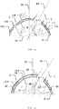
- a thermal weeder 1 as shown in Figures 10a and 10b produces hot air and at the outlet mouth for this hot air, is disposed a diffuser 2, for applying said hot air to an area to be treated.
- This diffuser 2 comprises a hollow body 103.
- This body 103 corresponds to the shield/bell 8 in the embodiments described above.
- This body 103 is substantially closed to the exclusion of three openings 4-6.
- a first opening 4 is shaped to fit and allow the mounting of the diffuser 2 on the outlet mouth of the weeder 1.
- This assembly is substantially airtight.
- a second opening 5 allows application of the diffuser 2 and therefore hot air on an area to be treated.
- At least a third opening 106 allows the air out of the diffuser 2.
- the diffuser 2 further comprises a limiting means capable of limiting the cooling of the air.
- this limiting means limits the cooling of the air, it can make it possible to increase the size of the diffuser 2 and particularly of its second opening 5 which determines the size of the treatable area.
- the limiting means comprises a thermal insulator 107.
- a thermal insulator 107 can be constituent of all or part of the body 103, arranged on the wall of the body 3 of the diffuser 2, over all or part of its inner face and/or its outer face.
- This insulator 107 can be of any type.
- the limiter means comprises at least one inner wall 108 and at least one outer wall 109 substantially parallel to each other.
- Such an arrangement of the body 103 comprising at least two walls can have many advantages with regard to the problems under consideration.
- the space between the two walls 108, 109 contains air and thus forms an insulator which limits the cooling of the air.
- the space between the two walls 108, 109 is advantageously used to house an insulator 107, such as for example a foam-type insulator or a metal straw type.
- the limitation is obtained by forcing the air to lengthen its circulation 10 in the diffuser 2.
- Circulation 10 can be performed in different ways and force the air to circulate longer in the chamber formed by the diffuser 2 or in the thickness of the diffuser 2.
- the body 103 comprises at least one inner wall 108 and at least one outer wall 109 substantially parallel to each other.
- the third opening 106 which allows the exit of the air to the outside, is decomposed into at least one inner orifice 61 pierced in the inner wall 108 and at least one outer orifice 62 pierced in the outer wall 109.
- Said at least one inner orifice 61 is disposed relative to said at least one outer orifice 62 so as to form, between the two walls 108, 109, at least one elongated circulation 10 that is as long as possible.
- Another way to limit the cooling of the air is to promote its circulation by freeing a portion of the volume enveloped by the diffuser 2.
- the second opening 5 may be closed by a grid 11.
- This grid 11 is able to rest on and to press the plants against the ground, preventing them from filling the entire interior volume of the diffuser 2. This promotes a better air circulation within the remaining volume, above the grid 11.
- the grid 11 is advantageously withdrawn or recessed within the inside of the diffuser 2.
- the grid 11 may comprise at least one substantially tubular protuberance 12 extending towards the second opening 5.
- the purpose of this at least one tubular protuberance 12 is to provide a guide for the hot air to the heart of the plants, already pressed by the grid 11.
- These protuberances 12 typically start from the grid 11 and extend towards the plane 13 on which the diffuser 2 will lay in use.
- their length is such that they do not reach said plane 13.
- the first opening 4 has a shape capable of allowing a dismountable assembly on a mouth of a weeder 1, preferably without tools. This is achieved by any known means, such as the techniques used to mount/dismount a diffuser on a heat gun.
- the second opening 5 has a plane outline - a periphery that lies in a plane.
- the diffuser 2 can be placed on the ground thus delimiting an area to be treated. If the ground is substantially flat, the ground closes, substantially tightly, the diffuser chamber 2. This allows the definition of a laying plane 13, which merges advantageously with the ground.
- the second opening 5 has a contour (or periphery) comprising at least one rectilinear segment. This facilitates the treatment of a rectilinear border, allowing the diffuser 2 to be put closer to said border. This is illustrated in Figures 10a, 10b .
- the second opening 5 has a contour (or periphery) comprising at least two rectilinear segments having between them an angle at most equal to 90°. This facilitates the treatment of a re-entrant corner between two rectilinear edges, allowing the diffuser 2 to be placed as close as possible to said corner. This is illustrated in Figures 10a and 10b .
- the rectilinear segment may or may not be one of the two rectilinear segments.
- the second opening may have, for example, a triangular shape - see Figure 10b , or a substantially rectangular shape - see Figure 10a .
- the axis 14 of the first opening 4 which is substantially aligned with the axis of the weeder, is not parallel to the axis 15 of the second opening 5. This allows the axis 14 of the weeder to not be parallel to the axis 15 of the second opening. This allows easy handling of the weeder where its axis 14 is not perpendicular to the laying plane 13.
- the diffuser can be made of any material. Given the temperatures used, say up to or greater than 500°C, preference is given to metal materials, and particularly: steel, stainless steel, and aluminium but in some cases use of other materials might be desirable, say carbon fibre, reinforced plastic, composite materials etc. As above these ideas may be embodied in a diffuser or a thermal weeder 1 equipped with such a diffuser. The ideas are particularly suitable for use with a thermal weeder 1 of the electric type.
Landscapes
- Life Sciences & Earth Sciences (AREA)
- Engineering & Computer Science (AREA)
- Insects & Arthropods (AREA)
- Pest Control & Pesticides (AREA)
- Wood Science & Technology (AREA)
- Zoology (AREA)
- Environmental Sciences (AREA)
- Soil Working Implements (AREA)
- Catching Or Destruction (AREA)
Priority Applications (1)
| Application Number | Priority Date | Filing Date | Title |
|---|---|---|---|
| EP24151976.8A EP4331357A2 (de) | 2018-03-15 | 2019-03-14 | Thermischer unkrautdiffusor |
Applications Claiming Priority (3)
| Application Number | Priority Date | Filing Date | Title |
|---|---|---|---|
| FR1852236A FR3078861B1 (fr) | 2018-03-15 | 2018-03-15 | Diffuseur pour desherbeur |
| FR1852237A FR3078860B1 (fr) | 2018-03-15 | 2018-03-15 | Diffuseur pour desherbeur |
| GB1814212.5A GB2572026B (en) | 2018-03-15 | 2018-08-31 | Thermal Weeders |
Related Child Applications (2)
| Application Number | Title | Priority Date | Filing Date |
|---|---|---|---|
| EP24151976.8A Division-Into EP4331357A2 (de) | 2018-03-15 | 2019-03-14 | Thermischer unkrautdiffusor |
| EP24151976.8A Division EP4331357A2 (de) | 2018-03-15 | 2019-03-14 | Thermischer unkrautdiffusor |
Publications (3)
| Publication Number | Publication Date |
|---|---|
| EP3539378A1 true EP3539378A1 (de) | 2019-09-18 |
| EP3539378C0 EP3539378C0 (de) | 2024-03-13 |
| EP3539378B1 EP3539378B1 (de) | 2024-03-13 |
Family
ID=65686783
Family Applications (1)
| Application Number | Title | Priority Date | Filing Date |
|---|---|---|---|
| EP19162910.4A Active EP3539378B1 (de) | 2018-03-15 | 2019-03-14 | Diffusor eines thermischen unkrautvernichters |
Country Status (1)
| Country | Link |
|---|---|
| EP (1) | EP3539378B1 (de) |
Citations (7)
| Publication number | Priority date | Publication date | Assignee | Title |
|---|---|---|---|---|
| EP0649944A1 (de) * | 1993-10-23 | 1995-04-26 | BTC Biotechnik International GmbH | Vorrichtung zur Beseitigung unerwünschten Pflanzenwuchses auf befestigten Flächen |
| US6029589A (en) * | 1998-12-07 | 2000-02-29 | Simpson; Stephen | Portable steam weed killing apparatus |
| EP1038440A1 (de) * | 1999-03-19 | 2000-09-27 | WR Damp ApS | Vorrichtung zur Beseitigung unerwünschten Pflanzenwuchses mittels Dampf |
| FR2823644A1 (fr) * | 2001-04-23 | 2002-10-25 | C D Sarl | Procede de desherbage thermique de vegetaux au sol et dispositif pour sa mise en oeuvre |
| FR2841633A1 (fr) * | 2002-06-27 | 2004-01-02 | Gerard Jaulent | Dispositif a combustion du type bruleur a gaz et son procede de travail |
| US20170290325A1 (en) * | 2016-04-08 | 2017-10-12 | Zhejiang Prulde Electric Appliance Co., Ltd. | Weed removing tool |
| WO2017201637A1 (zh) * | 2016-05-25 | 2017-11-30 | 杨伟明 | 一种防热回流的除草机用喷嘴 |
-
2019
- 2019-03-14 EP EP19162910.4A patent/EP3539378B1/de active Active
Patent Citations (7)
| Publication number | Priority date | Publication date | Assignee | Title |
|---|---|---|---|---|
| EP0649944A1 (de) * | 1993-10-23 | 1995-04-26 | BTC Biotechnik International GmbH | Vorrichtung zur Beseitigung unerwünschten Pflanzenwuchses auf befestigten Flächen |
| US6029589A (en) * | 1998-12-07 | 2000-02-29 | Simpson; Stephen | Portable steam weed killing apparatus |
| EP1038440A1 (de) * | 1999-03-19 | 2000-09-27 | WR Damp ApS | Vorrichtung zur Beseitigung unerwünschten Pflanzenwuchses mittels Dampf |
| FR2823644A1 (fr) * | 2001-04-23 | 2002-10-25 | C D Sarl | Procede de desherbage thermique de vegetaux au sol et dispositif pour sa mise en oeuvre |
| FR2841633A1 (fr) * | 2002-06-27 | 2004-01-02 | Gerard Jaulent | Dispositif a combustion du type bruleur a gaz et son procede de travail |
| US20170290325A1 (en) * | 2016-04-08 | 2017-10-12 | Zhejiang Prulde Electric Appliance Co., Ltd. | Weed removing tool |
| WO2017201637A1 (zh) * | 2016-05-25 | 2017-11-30 | 杨伟明 | 一种防热回流的除草机用喷嘴 |
Also Published As
| Publication number | Publication date |
|---|---|
| EP3539378C0 (de) | 2024-03-13 |
| EP3539378B1 (de) | 2024-03-13 |
Similar Documents
| Publication | Publication Date | Title |
|---|---|---|
| US20190281809A1 (en) | Thermal weeders | |
| US9950799B2 (en) | Shielded anti-icing system and methods | |
| US10028499B2 (en) | Apparatus, assembly and method for manual and localized weeding | |
| CA2231109A1 (en) | Plasma arc torch | |
| EP3539378B1 (de) | Diffusor eines thermischen unkrautvernichters | |
| US20140110391A1 (en) | Oven baffle | |
| EP2212050B1 (de) | Schutzgaskammer zum schweissen oder waermebehandeln | |
| US10660233B2 (en) | Protective apparatus usable with a forced air cooling system and electrical enclosure | |
| DE19949724A1 (de) | Wrasenkanal für Garofen | |
| EP3501276B1 (de) | Verfahren zur thermischen wildkrautbeseitigung | |
| DE102008032833A1 (de) | Nahrungsmittelbehandlungsgerät | |
| JP2010203632A (ja) | バーナーカバー及びこれを用いた加熱調理器 | |
| WO2017201637A1 (zh) | 一种防热回流的除草机用喷嘴 | |
| EP3770511A1 (de) | Elektrischer konvektionsbackofen und verfahren zum betrieb eines elektrischen konvektionsbackofens | |
| EP3019315B1 (de) | Formwerkzeug und verfahren | |
| US20180043193A1 (en) | Fire-fight ventilator with ovalised air jet | |
| EP3722679B1 (de) | Professioneller kochofen mit dampferzeuger | |
| US20170336098A1 (en) | Hot Air Nozzle and its Production Method | |
| JP6671169B2 (ja) | 加工用ノズルおよび加工装置 | |
| CN111972999B (zh) | 一种烹饪装置 | |
| KR101778769B1 (ko) | 노즐 일체형 토치헤드 및 이를 포함하는 용접장치 | |
| CN217218394U (zh) | 电吹风及其附件 | |
| DE102019117148B4 (de) | Ansauggehäuse und Vorrichtung umfassend ein Ansauggehäuse zur Absaugung von Wra-sen sowie Verfahren zur Absaugung von Wrasen mittels der Vorrichtung und Verwendung der Vorrichtung zur Absaugung von Wrasen | |
| EP3038435A1 (de) | Plasmabrenner | |
| JP2001043801A (ja) | 陰極線管用防爆バンドの装着方法 |
Legal Events
| Date | Code | Title | Description |
|---|---|---|---|
| PUAI | Public reference made under article 153(3) epc to a published international application that has entered the european phase |
Free format text: ORIGINAL CODE: 0009012 |
|
| STAA | Information on the status of an ep patent application or granted ep patent |
Free format text: STATUS: THE APPLICATION HAS BEEN PUBLISHED |
|
| AK | Designated contracting states |
Kind code of ref document: A1 Designated state(s): AL AT BE BG CH CY CZ DE DK EE ES FI FR GB GR HR HU IE IS IT LI LT LU LV MC MK MT NL NO PL PT RO RS SE SI SK SM TR |
|
| AX | Request for extension of the european patent |
Extension state: BA ME |
|
| STAA | Information on the status of an ep patent application or granted ep patent |
Free format text: STATUS: REQUEST FOR EXAMINATION WAS MADE |
|
| 17P | Request for examination filed |
Effective date: 20200317 |
|
| RBV | Designated contracting states (corrected) |
Designated state(s): AL AT BE BG CH CY CZ DE DK EE ES FI FR GB GR HR HU IE IS IT LI LT LU LV MC MK MT NL NO PL PT RO RS SE SI SK SM TR |
|
| STAA | Information on the status of an ep patent application or granted ep patent |
Free format text: STATUS: EXAMINATION IS IN PROGRESS |
|
| 17Q | First examination report despatched |
Effective date: 20220303 |
|
| GRAP | Despatch of communication of intention to grant a patent |
Free format text: ORIGINAL CODE: EPIDOSNIGR1 |
|
| STAA | Information on the status of an ep patent application or granted ep patent |
Free format text: STATUS: GRANT OF PATENT IS INTENDED |
|
| INTG | Intention to grant announced |
Effective date: 20230927 |
|
| GRAS | Grant fee paid |
Free format text: ORIGINAL CODE: EPIDOSNIGR3 |
|
| GRAA | (expected) grant |
Free format text: ORIGINAL CODE: 0009210 |
|
| STAA | Information on the status of an ep patent application or granted ep patent |
Free format text: STATUS: THE PATENT HAS BEEN GRANTED |
|
| RAP3 | Party data changed (applicant data changed or rights of an application transferred) |
Owner name: EXEL INDUSTRIES |
|
| AK | Designated contracting states |
Kind code of ref document: B1 Designated state(s): AL AT BE BG CH CY CZ DE DK EE ES FI FR GB GR HR HU IE IS IT LI LT LU LV MC MK MT NL NO PL PT RO RS SE SI SK SM TR |
|
| REG | Reference to a national code |
Ref country code: GB Ref legal event code: FG4D |
|
| REG | Reference to a national code |
Ref country code: CH Ref legal event code: EP |
|
| REG | Reference to a national code |
Ref country code: DE Ref legal event code: R096 Ref document number: 602019048087 Country of ref document: DE |
|
| U01 | Request for unitary effect filed |
Effective date: 20240313 |
|
| U07 | Unitary effect registered |
Designated state(s): AT BE BG DE DK EE FI FR IT LT LU LV MT NL PT SE SI Effective date: 20240320 |
|
| U20 | Renewal fee paid [unitary effect] |
Year of fee payment: 6 Effective date: 20240327 |