EP3539243B1 - Synchronization signal transmission techniques for peak-to-average power ratio reduction - Google Patents
Synchronization signal transmission techniques for peak-to-average power ratio reduction Download PDFInfo
- Publication number
- EP3539243B1 EP3539243B1 EP17784096.4A EP17784096A EP3539243B1 EP 3539243 B1 EP3539243 B1 EP 3539243B1 EP 17784096 A EP17784096 A EP 17784096A EP 3539243 B1 EP3539243 B1 EP 3539243B1
- Authority
- EP
- European Patent Office
- Prior art keywords
- synchronization signal
- component carriers
- base station
- synchronization signals
- synchronization
- Prior art date
- Legal status (The legal status is an assumption and is not a legal conclusion. Google has not performed a legal analysis and makes no representation as to the accuracy of the status listed.)
- Active
Links
Images


Classifications
-
- H—ELECTRICITY
- H04—ELECTRIC COMMUNICATION TECHNIQUE
- H04J—MULTIPLEX COMMUNICATION
- H04J1/00—Frequency-division multiplex systems
- H04J1/02—Details
-
- H—ELECTRICITY
- H04—ELECTRIC COMMUNICATION TECHNIQUE
- H04L—TRANSMISSION OF DIGITAL INFORMATION, e.g. TELEGRAPHIC COMMUNICATION
- H04L27/00—Modulated-carrier systems
- H04L27/26—Systems using multi-frequency codes
- H04L27/2601—Multicarrier modulation systems
- H04L27/2614—Peak power aspects
-
- H—ELECTRICITY
- H04—ELECTRIC COMMUNICATION TECHNIQUE
- H04L—TRANSMISSION OF DIGITAL INFORMATION, e.g. TELEGRAPHIC COMMUNICATION
- H04L5/00—Arrangements affording multiple use of the transmission path
- H04L5/0001—Arrangements for dividing the transmission path
- H04L5/0014—Three-dimensional division
- H04L5/0023—Time-frequency-space
-
- H—ELECTRICITY
- H04—ELECTRIC COMMUNICATION TECHNIQUE
- H04L—TRANSMISSION OF DIGITAL INFORMATION, e.g. TELEGRAPHIC COMMUNICATION
- H04L5/00—Arrangements affording multiple use of the transmission path
- H04L5/003—Arrangements for allocating sub-channels of the transmission path
- H04L5/0048—Allocation of pilot signals, i.e. of signals known to the receiver
-
- H—ELECTRICITY
- H04—ELECTRIC COMMUNICATION TECHNIQUE
- H04L—TRANSMISSION OF DIGITAL INFORMATION, e.g. TELEGRAPHIC COMMUNICATION
- H04L5/00—Arrangements affording multiple use of the transmission path
- H04L5/02—Channels characterised by the type of signal
- H04L5/06—Channels characterised by the type of signal the signals being represented by different frequencies
-
- H—ELECTRICITY
- H04—ELECTRIC COMMUNICATION TECHNIQUE
- H04L—TRANSMISSION OF DIGITAL INFORMATION, e.g. TELEGRAPHIC COMMUNICATION
- H04L7/00—Arrangements for synchronising receiver with transmitter
- H04L7/04—Speed or phase control by synchronisation signals
- H04L7/041—Speed or phase control by synchronisation signals using special codes as synchronising signal
-
- H—ELECTRICITY
- H04—ELECTRIC COMMUNICATION TECHNIQUE
- H04W—WIRELESS COMMUNICATION NETWORKS
- H04W52/00—Power management, e.g. Transmission Power Control [TPC] or power classes
- H04W52/04—Transmission power control [TPC]
- H04W52/30—Transmission power control [TPC] using constraints in the total amount of available transmission power
- H04W52/36—Transmission power control [TPC] using constraints in the total amount of available transmission power with a discrete range or set of values, e.g. step size, ramping or offsets
-
- H—ELECTRICITY
- H04—ELECTRIC COMMUNICATION TECHNIQUE
- H04W—WIRELESS COMMUNICATION NETWORKS
- H04W56/00—Synchronisation arrangements
- H04W56/001—Synchronization between nodes
-
- H—ELECTRICITY
- H04—ELECTRIC COMMUNICATION TECHNIQUE
- H04W—WIRELESS COMMUNICATION NETWORKS
- H04W72/00—Local resource management
- H04W72/04—Wireless resource allocation
- H04W72/044—Wireless resource allocation based on the type of the allocated resource
- H04W72/0453—Resources in frequency domain, e.g. a carrier in FDMA
-
- H—ELECTRICITY
- H04—ELECTRIC COMMUNICATION TECHNIQUE
- H04L—TRANSMISSION OF DIGITAL INFORMATION, e.g. TELEGRAPHIC COMMUNICATION
- H04L27/00—Modulated-carrier systems
- H04L27/26—Systems using multi-frequency codes
- H04L27/2601—Multicarrier modulation systems
- H04L27/2614—Peak power aspects
- H04L27/2621—Reduction thereof using phase offsets between subcarriers
-
- H—ELECTRICITY
- H04—ELECTRIC COMMUNICATION TECHNIQUE
- H04L—TRANSMISSION OF DIGITAL INFORMATION, e.g. TELEGRAPHIC COMMUNICATION
- H04L5/00—Arrangements affording multiple use of the transmission path
- H04L5/0001—Arrangements for dividing the transmission path
- H04L5/0003—Two-dimensional division
- H04L5/0005—Time-frequency
- H04L5/0007—Time-frequency the frequencies being orthogonal, e.g. OFDM(A) or DMT
- H04L5/001—Time-frequency the frequencies being orthogonal, e.g. OFDM(A) or DMT the frequencies being arranged in component carriers
-
- Y—GENERAL TAGGING OF NEW TECHNOLOGICAL DEVELOPMENTS; GENERAL TAGGING OF CROSS-SECTIONAL TECHNOLOGIES SPANNING OVER SEVERAL SECTIONS OF THE IPC; TECHNICAL SUBJECTS COVERED BY FORMER USPC CROSS-REFERENCE ART COLLECTIONS [XRACs] AND DIGESTS
- Y02—TECHNOLOGIES OR APPLICATIONS FOR MITIGATION OR ADAPTATION AGAINST CLIMATE CHANGE
- Y02D—CLIMATE CHANGE MITIGATION TECHNOLOGIES IN INFORMATION AND COMMUNICATION TECHNOLOGIES [ICT], I.E. INFORMATION AND COMMUNICATION TECHNOLOGIES AIMING AT THE REDUCTION OF THEIR OWN ENERGY USE
- Y02D30/00—Reducing energy consumption in communication networks
- Y02D30/70—Reducing energy consumption in communication networks in wireless communication networks
Definitions
- the following relates generally to wireless communication at a base station, and more specifically to synchronization signal transmission techniques for peak-to-average power ratio (PAPR) reduction.
- PAPR peak-to-average power ratio
- Wireless communications systems are widely deployed to provide various types of communication content such as voice, video, packet data, messaging, broadcast, and so on. These systems may be capable of supporting communication with multiple users by sharing the available system resources (e.g., time, frequency, and power).
- multiple-access systems include code division multiple access (CDMA) systems, time division multiple access (TDMA) systems, frequency division multiple access (FDMA) systems, and orthogonal frequency division multiple access (OFDMA) systems, (e.g., a Long Term Evolution (LTE) system, or a New Radio (NR) system).
- CDMA code division multiple access
- TDMA time division multiple access
- FDMA frequency division multiple access
- OFDMA orthogonal frequency division multiple access
- LTE Long Term Evolution
- NR New Radio
- a wireless multiple-access communications system may include a number of base stations or access network nodes, each simultaneously supporting communication for multiple communication devices, which may be otherwise known as user equipment (UE).
- UE user equipment
- QUALCOMM INCORPORATED "Time Accuracy for Contiguous Carrier Aggregation", 3GPP DRAFT; R4-103053 discloses avoiding a high MPR due to increased cubic metric in a contiguous carrier aggregation case.
- QUALCOMM INCORPORATED “Multi-beam SYNC design", 3GPP DRAFT; R1 -1610159 discloses different aspects of the synchronization in a mmwave system.
- TEXAS INSTRUMENTS "Resolving CM and Cell ID Issues Associated with Aggregated Carriers", 3GPP DRAFT; R1-091839 discloses controlling CM for downlink transmissions by applying different phase offsets to different component carriers.
- QUALCOMM INCORPORATED “Multiplexing of waveforms for SYNC", 3GPP DRAFT; R1-1612026 discloses comparing different multiplexing methids to transmit sync signals within a SS block.
- QUALCOMM INCORPORATED “Multi-beam SYNC design”, 3GPP DRAFT; R1-1612024 discloses different aspects of synchronization in a mmwave system.
- a method performed by a base station and a base station are defined by the appended independent claims 1, 14 respectively.
- the invention is defined by the appended claims.
- Some examples of the method, apparatus, and non-transitory computer-readable medium described above may further include processes, features, means, or instructions for identifying the set of phase offsets based at least in part on a number of component carriers of a set of component carriers, or a sequence of synchronization signals associated with different component carriers of the set of component carriers, or both.
- Some examples of the method, apparatus, and non-transitory computer-readable medium described above may further include processes, features, means, or instructions for identifying a PAPR or a cubic metric (CM) associated with the set of phase offsets, wherein identifying the set of phase offsets may be based at least in part on minimizing the identified PAPR or the identified CM.
- CM cubic metric
- Some examples of the method, apparatus, and non-transitory computer-readable medium described above may further include processes, features, means, or instructions for identifying a PAPR or a CM associated with the set of phase offsets, wherein identifying the set of phase offsets may be based at least in part on whether the identified PAPR or the identified CM may be less than a predetermined threshold.
- Some examples of the method, apparatus, and non-transitory computer-readable medium described above may further include processes, features, means, or instructions for selecting one or more sequences for the set of synchronization signals.
- the one or more sequences comprise a Zadoff-Chu sequence, or a M sequence, or a combination thereof.
- selecting the one or more sequences comprises: selecting one or more combinations of a root and a cyclic shift of a Zadoff-Chu sequence that minimizes a PAPR or a CM.
- Some examples of the method, apparatus, and non-transitory computer-readable medium described above may further include processes, features, means, or instructions for selecting one or more combinations of a polynomial and a cyclic shift of a M sequence that minimized the PAPR or the CM.
- selecting the one or more sequences comprises: selecting one or more combinations of a root and a cyclic shift of a Zadoff-Chu sequence that corresponds to a PAPR value or a CM value that may be below a predetermined threshold.
- Some examples of the method, apparatus, and non-transitory computer-readable medium described above may further include processes, features, means, or instructions for selecting one or more combinations of a polynomial and a cyclic shift of an M sequence that corresponds to a PAPR value or a CM value that may be below a predetermined threshold.
- a method of wireless communication may include identifying a set of synchronization signal blocks and transmitting each synchronization signal block of the set of synchronization signal blocks, each synchronization signal block being transmitted on one or more component carriers of a set of component carriers or transmitted simultaneously on a wideband carrier.
- the apparatus may include means for identifying a set of synchronization signal blocks and means for transmitting each synchronization signal block of the set of synchronization signal blocks, each synchronization signal block being transmitted on one or more component carriers of a set of component carriers or transmitted simultaneously on a wideband carrier.
- transmitting each synchronization signal block comprises: transmitting each synchronization signal block using a first beam configuration having a first width greater than a second width of a second beam configuration, the second beam configuration associated with transmitting a synchronization signal block over multiple component carriers of the set of component carriers from a same antenna port.
- Some wireless communication systems may operate in millimeter wave (mmW) frequency ranges, e.g., 28 GHz, 40 GHz, 60 GHz, etc.
- Wireless communication at these frequencies may be associated with increased signal attenuation (e.g., path loss), which may be influenced by various factors, such as temperature, barometric pressure, diffraction, etc.
- signal processing techniques such as beamforming, may be used to coherently combine energy and overcome the path losses at these frequencies.
- a base station e.g., including primary synchronization signals (PSSs), secondary synchronization signals (SSSs), and physical broadcast channels (PBCHs)
- PSSs primary synchronization signals
- SSSs secondary synchronization signals
- PBCHs physical broadcast channels
- synchronization signals may utilize beamforming techniques to meet a link budget.
- a base station may use several antenna ports ( e.g., 1, 2, 4, 8 antenna ports) connected to subarrays of antennas to form beams in various directions using a number of analog weight factors, and synchronization signals associated with the antenna ports may be transmitted in different directions. That is, the base station may sweep beams in multiple directions, where the synchronization signal may be transmitted for a relatively short duration in each direction.
- Synchronization signals may be transmitted by a base station using time division multiplexing (TDM) or frequency division multiplexing (FDM), although TDM may, in some cases, be associated with a reduced peak-to-average power ratio (PAPR) of synchronization signals, such as PSSs.
- TDM time division multiplexing
- FDM frequency division multiplexing
- PAPR peak-to-average power ratio
- PSS peak-to-average power ratio
- the PSS is transmitted using multiple component carriers (such as with the simultaneous transmission of PSS in multiple directions from different antenna ports) the reduction of PAPR for synchronization signals may not be maintained through the use of TDM alone. Accordingly, there may be techniques in which signals may be transmitted using TDM or FDM that reduce the PAPR (or cubic metric (CM)) of synchronization signals.
- CM cubic metric
- a base station may use a selected set of phase offsets for the transmission of synchronization signals (e.g., PSSs) that are simultaneously transmitted using FDM, where a different phase offset may be applied to one or more synchronization signals transmitted on one or more component carriers. That is, a first synchronization signal transmitted in a first component carrier is phase shifted (e.g., using a first phase offset) relative to a second synchronization signal transmitted in a second component carrier (e.g., using a second phase offset). The synchronization signal may then be transmitted during a symbol period on the one or more component carriers. For example, the synchronization signals is transmitted on different component carriers.
- synchronization signals e.g., PSSs
- a UE 115 may also be a cellular phone, a personal digital assistant (PDA), a wireless modem, a wireless communication device, a handheld device, a tablet computer, a laptop computer, a cordless phone, a personal electronic device, a handheld device, a personal computer, a wireless local loop (WLL) station, an Internet of things (IoT) device, an Internet of Everything (IoE) device, a machine type communication (MTC) device, an appliance, an automobile, or the like.
- PDA personal digital assistant
- WLL wireless local loop
- IoT Internet of things
- IoE Internet of Everything
- MTC machine type communication
- a UE 115 may also be able to communicate directly with other UEs (e.g., using a peer-to-peer (P2P) or device-to-device (D2D) protocol).
- P2P peer-to-peer
- D2D device-to-device
- One or more of a group of UEs 115 utilizing D2D communications may be within the coverage area 110 of a cell. Other UEs 115 in such a group may be outside the coverage area 110 of a cell, or otherwise unable to receive transmissions from a base station 105.
- groups of UEs 115 communicating via D2D communications may utilize a one-to-many (1:M) system in which each UE 115 transmits to every other UE 115 in the group.
- a base station 105 facilitates the scheduling of resources for D2D communications.
- D2D communications are carried out independent of a base station 105.
- Base stations 105 may communicate with the core network 130 and with one another. For example, base stations 105 may interface with the core network 130 through backhaul links 132 (e.g., S1, etc. ) . Base stations 105 may communicate with one another over backhaul links 134 ( e.g., X2, etc .) either directly or indirectly ( e.g., through core network 130). Base stations 105 may perform radio configuration and scheduling for communication with UEs 115, or may operate under the control of a base station controller (not shown). In some examples, base stations 105 may be macro cells, small cells, hot spots, or the like. Base stations 105 may also be referred to as eNodeBs (eNBs) 105.
- eNodeBs eNodeBs
- Wireless communications system 100 may operate in an ultra-high frequency (UHF) frequency region using frequency bands from 700 MHz to 2600 MHz (2.6 GHz), although in some cases wireless local area networks (WLANs) may use frequencies as high as 5 GHz. This region may also be known as the decimeter band, since the wavelengths range from approximately one decimeter to one meter in length.
- UHF waves may propagate mainly by line of sight, and may be blocked by buildings and environmental features. However, the waves may penetrate walls sufficiently to provide service to UEs 115 located indoors. Transmission of UHF waves is characterized by smaller antennas and shorter range ( e.g., less than 100 km) compared to transmission using the smaller frequencies (and longer waves) of the high frequency (HF) or very high frequency (VHF) portion of the spectrum.
- UHF high frequency
- VHF very high frequency
- wireless communications system 100 may also utilize extremely high frequency (EHF) portions of the spectrum (e.g., from 30 GHz to 300 GHz). This region may also be known as the millimeter band, since the wavelengths range from approximately one millimeter to one centimeter in length.
- EHF antennas may be even smaller and more closely spaced than UHF antennas. In some cases, this may facilitate use of antenna arrays within a UE 115 ( e.g., for directional beamforming).
- EHF transmissions may be subject to even greater atmospheric attenuation and shorter range than UHF transmissions.
- Wireless communications system 100 may support millimeter wave (mmW) communications between UEs 115 and base stations 105.
- Devices operating in mmW or EHF bands may have multiple antennas to allow beamforming. That is, a base station 105 may use multiple antennas or antenna arrays to conduct beamforming operations for directional communications with a UE 115.
- Beamforming (which may also be referred to as spatial filtering or directional transmission) is a signal processing technique that may be used at a transmitter (e.g . a base station 105) to shape and/or steer an overall antenna beam in the direction of a target receiver (e.g. a UE 115). This may be achieved by combining elements in an antenna array in such a way that transmitted signals at particular angles experience constructive interference while others experience destructive interference.
- MIMO wireless systems use a transmission scheme between a transmitter (e.g. a base station 105) and a receiver (e.g. a UE 115), where both transmitter and receiver are equipped with multiple antennas.
- Some portions of wireless communications system 100 may use beamforming.
- base station 105 may have an antenna array with a number of rows and columns of antenna ports that the base station 105 may use for beamforming in its communication with UE 115. Signals may be transmitted multiple times in different directions ( e.g., each transmission may be beamformed differently).
- a mmW receiver e.g., a UE 115
- the antennas of a base station 105 or UE 115 may be located within one or more antenna arrays, which may support beamforming or MIMO operation.
- One or more base station antennas or antenna arrays may be collocated at an antenna assembly, such as an antenna tower.
- antennas or antenna arrays associated with a base station 105 may be located in diverse geographic locations.
- a base station 105 may use multiple antennas or antenna arrays to conduct beamforming operations for directional communications with a UE 115.
- SFN system frame number
- Each frame may include ten 1 ms subframes numbered from 0 to 9.
- a subframe may be further divided into two 0.5 ms slots, each of which contains 6 or 7 modulation symbol periods (depending on the length of the cyclic prefix prepended to each symbol). Excluding the cyclic prefix, each symbol contains 2048 sample periods.
- the subframe may be the smallest scheduling unit, also known as a TTI.
- a TTI may be shorter than a subframe or may be dynamically selected (e.g., in short TTI bursts or in selected component carriers using short TTIs).
- Wireless communications system 100 may support operation on multiple cells or carriers, a feature which may be referred to as carrier aggregation (CA) or multi-carrier operation.
- a carrier may also be referred to as a component carrier, a layer, a channel, etc.
- the terms "carrier,” “component carrier,” “cell,” and “channel” may be used interchangeably herein.
- a UE 115 may be configured with multiple downlink component carriers and one or more uplink component carriers for carrier aggregation.
- Carrier aggregation may be used with both frequency division duplexed (FDD) and time division duplexed (TDD) component carriers.
- FDD frequency division duplexed
- TDD time division duplexed
- wireless communications system 100 may utilize enhanced component carriers (eCCs).
- eCC may be characterized by one or more features including: wider bandwidth, shorter symbol duration, shorter TTIs, and modified control channel configuration.
- an eCC may be associated with a carrier aggregation configuration or a dual connectivity configuration (e.g., when multiple serving cells have a suboptimal or non-ideal backhaul link).
- An eCC may also be configured for use in unlicensed spectrum or shared spectrum (where more than one operator is allowed to use the spectrum).
- An eCC characterized by wide bandwidth may include one or more segments that may be utilized by UEs 115 that are not capable of monitoring the whole bandwidth or prefer to use a limited bandwidth ( e.g., to conserve power).
- a device such as a UE 115 or base station 105, utilizing eCCs may transmit wideband signals (e.g., 20, 40, 60, 80 MHz, etc .) at reduced symbol durations ( e.g., 16.67 microseconds).
- a TTI in eCC may consist of one or multiple symbols. In some cases, the TTI duration (that is, the number of symbols in a TTI) may be variable.
- a UE 115 attempting to access a wireless network may perform an initial cell search by detecting a PSS from a base station 105.
- the PSS may enable synchronization of slot timing and may indicate a physical layer identity value.
- the UE 115 may then receive an SSS.
- the SSS may enable radio frame synchronization, and may provide a cell identity value, which may be combined with the physical layer identity value to identify the cell.
- the SSS may also enable detection of a duplexing mode and a cyclic prefix length.
- Some systems, such as TDD systems may transmit an SSS but not a PSS. Both the PSS and the SSS may be located in the central 62 and 72 subcarriers of a carrier, respectively.
- the UE 115 may receive a master information block (MIB), which may be transmitted in the physical broadcast channel (PBCH).
- the MIB may contain system bandwidth information, a system frame number (SFN), and a physical hybrid automatic repeat request (HARQ) indicator channel (PHICH) configuration.
- SIBs system information blocks
- SIB1 may contain cell access parameters and scheduling information for other SIBs. Decoding SIB1 may enable the UE 115 to receive SIB2.
- SIB2 may contain radio resource control (RRC) configuration information related to random access channel (RACH) procedures, paging, physical uplink control channel (PUCCH), physical uplink shared channel (PUSCH), power control, sounding reference signal (SRS), and cell barring.
- RRC radio resource control
- synchronization signals that are transmitted using beamforming may be used to identify a best transmission and reception beam pair that meets a certain link budget (such as with a RACH Message-2).
- synchronization signals in the frequency domain may be limited to a minimum bandwidth.
- synchronization signal transmissions may be associated with a bandwidth between 35 MHz and 40 MHz.
- orthogonal frequency division multiplexing (OFDM) symbols used for synchronization signals may not be frequency division multiplexed with other signals, which may support a full transmission power by a base station.
- Wireless communications system 100 may support the transmission of synchronization signals using a set of phase offsets that are simultaneously transmitted using FDM.
- the described techniques also provide for the transmission of synchronization signal blocks, where each synchronization signal block is transmitted on one or more component carriers or transmitted simultaneously on a wideband carrier.
- a base station 105 may identify a set of synchronization signals (e.g., a set of PSSs) to be transmitted over one or more component carriers.
- each PSS may be associated with a different component carrier, and the base station 105 may apply a different phase offset to each PSS when transmitting the set of PSSs on the different component carriers.
- the base station 105 may transmit the synchronization signal blocks on the component carriers using a different antenna port for each component carrier.
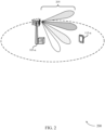
- FIG. 2 illustrates an example of a wireless communications system 200 for synchronization signal transmission techniques for PAPR reduction.
- Wireless communications system 200 may include a base station 105-a and a UE 115-a, which may be examples of the corresponding devices described with reference to FIG. 1 .
- Wireless communications system 200 may be an example of the transmission of PSS from base station 105-a using a set of phase offsets. Additionally or alternatively, wireless communications system 200 may be an example of the transmission of PSS in one component carrier for each antenna port.
- Wireless communications system 200 may be an example of a mmW communications system, and may accordingly use beamforming to overcome path loss within the system.
- the transmission of synchronization signals (e.g., PSSs, SSSs, PBCHs) from base station 105-a may be used by UE 115-a to synchronize its timing with base station 105-a.
- base station 105-a may use beams 205 to transmit synchronization signals in multiple directions, where different antenna ports of base station 105-a are used to transmit in the different directions.
- the synchronization signals transmitted by base station 105-a may be swept through each direction, where the signals corresponding to different directions may be transmitted in different symbol periods (e.g., OFDM symbols).
- base station 105-a may also refrain from multiplexing data with a PSS.
- base station 105-a may use a set of phase offsets for the transmission of synchronization signals sent simultaneously in an FDM manner, where a different phase offset is applied to synchronization signals transmitted on one or more component carriers.
- a first PSS transmitted in a first component carrier may be phase shifted relative to a second PSS in a second component carrier, where the PSSs may be simultaneously transmitted in the different component carriers.
- the application of the phase offsets to synchronization signals transmitted over a set of component carriers may reduce the PAPR of the transmitted signal.
- a PAPR associated with the transmission of PSSs including the phase offset may be lower than the PAPR when PSSs are transmitted without the phase offset.
- a component carrier may include PSS transmission for multiple antenna ports, where the antenna ports each transmit in different directions at the same time. Additionally or alternatively, the synchronization signals having different phase offsets may be transmitted in the frequency domain within a wideband carrier.
- Base station 105-a may use a number of techniques for the application of phase offsets to synchronization signals transmitted across one or more component carriers. For example, a phase ramp may be applied across synchronization signals that are associated with different component carriers, or a phase ramp may be applied across synchronization signals that are associated with a same component carrier.
- a sequence may also be used across different component carriers. For instance, a Zadoff-Chu or a maximum length (M) sequence may be applied across different component carriers. In such cases, a short Zadoff-Chu sequence or a short M sequence may be used across respective carriers. Additionally or alternatively, an extended Zadoff-Chu sequence or extended M sequence may be used across the different component carriers.
- Similar techniques may be used for choosing an M sequence such that the PAPR or CM of the system is minimized or remains below a predetermined threshold. For instance, a polynomial and a cyclic shift, or combinations thereof, may be selected to minimize the PAPR or CM, or both.
- each synchronization signal block may include a number of synchronization signals 320, which may include PSS, SSS, PBCH, or mobility reference signal (MRS), or a combination thereof.
- each synchronization signal block 315 may be associated with a direction transmission of synchronization signals. That is, synchronization signal blocks 315 in each symbol 310 may be designated for a transmission in a different direction.
- transmission scheme 400 may illustrate the transmission of eight different beams for two different antenna ports ( e.g., eight different directions for each antenna port) during four symbols 410.
- Transmission scheme 500 may include multiple antenna port transmissions 505 originating from different antenna ports of base station 105.
- Each antenna port transmission 505 may include multiple symbols 510 that correspond to a transmission of synchronization signals using multiple beams, where each beam ( e.g., b1 through b8) may be associated with a different direction.
- a first antenna port transmission 505-a may include four symbols 510 for eight different beams ( e.g., b1 through b8) from a first antenna port (AP1), where each symbol 510 is associated with two different beams.
- a second antenna port transmission 505-b may include four symbols 510 for eight different beams (e.g., b1 through b8) from a second antenna port (AP2).
- Synchronization signals sent by each antenna port transmission 505 may use a single component carriers 515.
- the PSSs in the first antenna port transmission 505-a and the second antenna port transmission 505-b may be sent using one component carrier 515.
- transmission scheme 500 may illustrate the transmission of eight different beams for two different antenna ports ( e.g., eight different directions for each antenna port) across four symbols 510, but using a single component carrier 515.
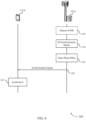
- FIG. 6 illustrates an example of a process flow 600 in a system that supports synchronization signal transmission techniques for PAPR reduction.
- Process flow 600 may include UE 115-b and base station 105-b, which may be examples of the corresponding devices described with reference to FIGs. 1 and 2 .
- base station 105-b and UE 115-b may operate in a mmW communications system.
- Process flow 600 may illustrate the application of a set of phases to synchronization signals transmitted across multiple component carriers.
- base station 105-b may optionally measure a current PAPR (or CM) within a system. In some examples, this measurement may be used to determine a set of phase offsets. Additionally or alternatively, this measurement may be a one-time measurement completed by base station 105-b.
- base station 105-b may identify the set of phase offsets based at least in part on a number of component carriers of the set of component carriers, or a sequence of the synchronization signals associated with the different component carriers of the set of component carriers, or both.
- Base station 105-b may also identify a PAPR or a CM associated with the set of phase offsets. Accordingly, identifying the set of phase offsets may be based on minimizing the identified PAPR or the identified CM.
- base station 105-b may identify the PAPR or the CM associated with the set of phase offsets, where identifying the set of phase offsets is based on whether the identified PAPR or the identified CM is less than a predetermined threshold.
- UE 115-a may achieve synchronization with base station 105-a based on the received PSS, SSS, and PBCH. That is, UE 115-a may identify a radio frame, a subframe, a slot, and a symbol synchronization in the time domain, and may proceed with access procedures with base station 105-a.
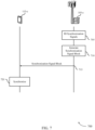
- base station 105-c may identify synchronization signals to be broadcast to multiple UEs 115 ( e.g., including UE 115-c). For example, a set of PSSs may be identified, where each PSS of the set of PSSs may be associated with a different component carrier of a set of component carriers. In some examples, each PSS of the set of PSSs is associated with a same PSS sequence.
- UE 115-c may achieve synchronization with base station 105-c based on the received PSS, SSS, and PBCH. That is, UE 115-c may identify a radio frame, a subframe, a slot, and a symbol synchronization in the time domain, and may proceed with access procedures with base station 105-c.
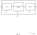
- Receiver 810 may receive information such as packets, user data, or control information associated with various information channels (e.g., control channels, data channels, and information related to synchronization signal transmission techniques for PAPR reduction, etc .) . Information may be passed on to other components of the device.
- the receiver 810 may be an example of aspects of the transceiver 1135 described with reference to FIG. 11 .
- Synchronization signal manager 815 may be an example of aspects of the synchronization signal manager 1115 described with reference to FIG. 11 .
- Synchronization signal manager 815 and/or at least some of its various sub-components may be implemented in hardware, software executed by a processor, firmware, or any combination thereof. If implemented in software executed by a processor, the functions of the synchronization signal manager 815 and/or at least some of its various sub-components may be executed by a general-purpose processor, a digital signal processor (DSP), an application-specific integrated circuit (ASIC), a field-programmable gate array (FPGA) or other programmable logic device, discrete gate or transistor logic, discrete hardware components, or any combination thereof designed to perform the functions described in the present disclosure.
- DSP digital signal processor
- ASIC application-specific integrated circuit
- FPGA field-programmable gate array
- the synchronization signal manager 815 and/or at least some of its various sub-components may be physically located at various positions, including being distributed such that portions of functions are implemented at different physical locations by one or more physical devices.
- synchronization signal manager 815 and/or at least some of its various sub-components may be a separate and distinct component in accordance with various aspects of the present disclosure.
- synchronization signal manager 815 and/or at least some of its various sub-components may be combined with one or more other hardware components, including but not limited to a receiver, a transmitter, a transceiver, one or more other components described in the present disclosure, or a combination thereof in accordance with various aspects of the present disclosure.
- FIG. 9 shows a block diagram 900 of wireless device 905 that supports synchronization signal transmission techniques for PAPR reduction in accordance with various aspects of the present disclosure.
- Wireless device 905 may be an example of aspects of a wireless device 805 or a base station 105 ( e.g., a base station that operates in mmW frequency spectrum) as described with reference to FIGs. 1 and 8 .
- Wireless device 905 may include receiver 910, synchronization signal manager 915, and transmitter 920.
- Wireless device 905 may also include a processor. Each of these components may be in communication with one another ( e.g., via one or more buses).
- Synchronization signal manager 915 may be an example of aspects of the synchronization signal manager 1115 described with reference to FIG. 11 . Synchronization signal manager 915 may also include synchronization signal component 925, phase offset component 930, and component carrier manager 935.
- Synchronization signal manager 915 and/or at least some of its various sub-components may be implemented in hardware, software executed by a processor, firmware, or any combination thereof. If implemented in software executed by a processor, the functions of the synchronization signal manager 915 and/or at least some of its various sub-components may be executed by a general-purpose processor, a DSP, an ASIC, a FPGA or other programmable logic device, discrete gate or transistor logic, discrete hardware components, or any combination thereof designed to perform the functions described in the present disclosure.
- the synchronization signal manager 915 and/or at least some of its various sub-components may be physically located at various positions, including being distributed such that portions of functions are implemented at different physical locations by one or more physical devices.
- synchronization signal manager 915 and/or at least some of its various sub-components may be a separate and distinct component in accordance with various aspects of the present disclosure.
- synchronization signal manager 915 and/or at least some of its various sub-components may be combined with one or more other hardware components, including but not limited to a receiver, a transmitter, a transceiver, one or more other components described in the present disclosure, or a combination thereof in accordance with various aspects of the present disclosure.
- Synchronization signal component 925 may identify a set of synchronization signals.
- each synchronization signal may be associated with a different component carrier of a set of component carriers.
- the set of synchronization signals includes PSSs, or SSSs, or a combination thereof.
- each synchronization signal of the set of synchronization signal is associated with a same sequence.
- synchronization signal component 925 may identify a set of synchronization signal blocks.
- each synchronization signal block includes at least one or more of a PSS, a SSS, a PBCH, and a DMRS of the PBCH.
- phase offset component 930 may identify a PAPR or a CM associated with the set of phase offsets, where identifying the set of phase offsets is based on whether the identified PAPR or the identified CM is less than a predetermined threshold.
- selecting the phase offset includes applying a phase ramp across the synchronization signals each associated with the different component carriers of the set of component carriers.
- selecting the phase offset includes applying a sequence across different component carriers of a set of component carriers.
- the sequence may include a short Zadoff-Chu sequence, or an extended Zadoff-Chu sequence, or a short M sequence, or an extended M sequence.
- selecting the phase offset includes applying a short Zadoff-Chu sequence across the different component carriers of the set of component carriers.
- selecting the phase offset includes applying an extended Zadoff-Chu sequence across the different component carriers of the set of component carriers.
- component carrier manager 935 may transmit each synchronization signal block of the set of synchronization signal blocks, each synchronization signal block being transmitted on one or more component carriers of a set of component carriers or transmitted simultaneously on a wideband carrier.
- transmitting each synchronization signal on one or more component carriers includes transmitting each synchronization signal in a different frequency band.
- transmitting each synchronization signal includes transmitting each synchronization signal on different component carriers of a set of component carriers, where each synchronization signal may be associated with a different component carrier of the set of component carriers.
- transmitting each PSS includes refraining from transmitting another signal while transmitting each synchronization signal. Additionally or alternatively, transmitting each synchronization signal includes refraining from transmitting a data signal while transmitting each synchronization signal.
- transmitting each synchronization signal block includes transmitting each synchronization signal block using a different antenna port of the base station or using a same antenna port of the base station. In some cases, transmitting each synchronization signal block on the one or more component carriers includes transmitting each synchronization signal block on different component carriers of the set of component carriers, each synchronization signal block associated with a different component carrier of the set of component carriers. In some examples, transmitting each synchronization signal block includes transmitting each synchronization signal block using a first beam configuration having a first width greater than a second width of a second beam configuration, the second beam configuration associated with transmitting a synchronization signal block over multiple component carriers of the set of component carriers from a same antenna port. In some cases, the first beam configuration is based at least in part on a plurality of beam directions. In some examples, transmitting each synchronization signal block includes refraining from transmitting another signal while transmitting each synchronization signal block.
- Transmitter 920 may transmit signals generated by other components of the device.
- the transmitter 920 may be collocated with a receiver 910 in a transceiver module.
- the transmitter 920 may be an example of aspects of the transceiver 1135 described with reference to FIG. 11 .
- the transmitter 920 may include a single antenna, or it may include a set of antennas.
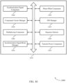
- FIG. 10 shows a block diagram 1000 of a synchronization signal manager 1015 that supports synchronization signal transmission techniques for PAPR reduction in accordance with various aspects of the present disclosure.
- the synchronization signal manager 1015 may be an example of aspects of a synchronization signal manager 815, a synchronization signal manager 915, or a synchronization signal manager 1115 described with reference to FIGs. 8 , 9 , and 11 .
- the synchronization signal manager 1015 may include synchronization signal component 1020, phase offset component 1025, component carrier manager 1030, SSS manager 1035, multiplexing component 1040, sequence selector 1045, synchronization signal block manager 1050, and transmit power component 1055. Each of these modules may communicate, directly or indirectly, with one another (e.g., via one or more buses).
- Synchronization signal manager 1015 and/or at least some of its various sub-components may be implemented in hardware, software executed by a processor, firmware, or any combination thereof. If implemented in software executed by a processor, the functions of the synchronization signal manager 1015 and/or at least some of its various sub-components may be executed by a general-purpose processor, a DSP, an ASIC, a FPGA or other programmable logic device, discrete gate or transistor logic, discrete hardware components, or any combination thereof designed to perform the functions described in the present disclosure.
- the synchronization signal manager 1015 and/or at least some of its various sub-components may be physically located at various positions, including being distributed such that portions of functions are implemented at different physical locations by one or more physical devices.
- synchronization signal manager 1015 and/or at least some of its various sub-components may be a separate and distinct component in accordance with various aspects of the present disclosure.
- synchronization signal manager 1015 and/or at least some of its various sub-components may be combined with one or more other hardware components, including but not limited to a receiver, a transmitter, a transceiver, one or more other components described in the present disclosure, or a combination thereof in accordance with various aspects of the present disclosure.
- Phase offset component 1025 may select a phase offset from a set of phase offsets for each synchronization signal of the set of synchronization signals and may identify the set of phase offsets based on a number of component carriers of the set of component carriers, or a sequence of the synchronization signals associated with the different component carriers of the set of component carriers, or both. In some examples, phase offset component 1025 may identify a PAPR or a CM associated with the set of phase offsets, where identifying the set of phase offsets is based on minimizing the identified PAPR or the identified CM.
- phase offset component 1025 may identify a PAPR or a CM associated with the set of phase offsets, where identifying the set of phase offsets is based on whether the identified PAPR or the identified CM is less than a predetermined threshold.
- selecting the phase offset includes applying a phase ramp across the synchronization signals each associated with the different component carriers of the set of component carriers.
- selecting the phase offset includes applying a sequence across different component carriers of a set of component carriers.
- the sequence may include a short Zadoff-Chu sequence, or an extended Zadoff-Chu sequence, or a short M sequence, or an extended M sequence.
- selecting the phase offset includes applying a short Zadoff-Chu sequence across the different component carriers of the set of component carriers.
- selecting the phase offset includes applying an extended Zadoff-Chu sequence across the different component carriers of the set of component carriers.
- Component carrier manager 1030 may transmit each synchronization signal on one or more component carriers of a set of component carriers using the selected phase offset. In some examples, component carrier manager 1030 may transmit the set of synchronization signals using the selected phase offsets, the set of synchronization signals being simultaneously transmitted using FDM. In some cases, transmitting the set of synchronization signals includes transmitting each synchronization signal on one or more component carriers of a set of component carriers. In some examples, transmitting each synchronization signal on the different component carriers includes transmitting each synchronization signal in a different radio frequency band. In some cases, transmitting the set of synchronization signals includes transmitting the set of synchronization signals simultaneously in a frequency domain within a wideband carrier.
- component carrier manager 1030 may transmit each synchronization signal block of the set of synchronization signal blocks, each synchronization signal block being transmitted on one or more component carriers of a set of component carriers or transmitted simultaneously on a wideband carrier.
- transmitting each synchronization signal on one or more component carriers includes transmitting each synchronization signal in a different frequency band.
- transmitting each synchronization signal includes transmitting each synchronization signal on different component carriers of a set of component carriers, where each synchronization signal may be associated with a different component carrier of the set of component carriers.
- transmitting each synchronization signal block includes refraining from transmitting another signal while transmitting each synchronization signal block. Additionally or alternatively, transmitting each synchronization signal block includes refraining from transmitting a data signal while transmitting each synchronization signal block.
- transmitting each synchronization signal block includes transmitting each synchronization signal block using a different antenna port of the base station or using a same antenna port of the base station. In some cases, transmitting each synchronization signal block on the one or more component carriers includes transmitting each synchronization signal block on different component carriers of the set of component carriers, each synchronization signal block associated with a different component carrier of the set of component carriers. In some examples, transmitting each synchronization signal block includes transmitting each synchronization signal block using a first beam configuration having a first width greater than a second width of a second beam configuration, the second beam configuration associated with transmitting a synchronization signal block over multiple component carriers of the set of component carriers from a same antenna port. In some cases, the first beam configuration is based at least in part on a plurality of beam directions. In some examples, transmitting each synchronization signal block includes refraining from transmitting another signal while transmitting each synchronization signal block.
- SSS manager 1035 may identify a set of SSSs.
- Multiplexing component 1040 may multiplex each PSS and each SSS of a set of synchronization signals using time division multiplexing.
- Sequence selector 1045 may select one or more sequences for the set of synchronization signals.
- the one or more sequences may include a Zadoff-Chu sequence, or a M sequence, or a combination thereof.
- selecting the Zadoff-Chu sequence includes selecting a root and a base sequence length of the Zadoff-Chu sequence that minimizes a PAPR or a CM.
- selecting the Zadoff-Chu sequence includes selecting a root and a base sequence length of the Zadoff-Chu sequence that corresponds to a PAPR value or a CM value that is below a predetermined threshold. In some cases, selecting the one or more sequences includes selecting one or more combinations of a root and a cyclic shift of a Zadoff-Chu sequence that minimizes a PAPR or a CM; or selecting one or more combinations of a polynomial and a cyclic shift of an M sequence that minimized the PAPR or the CM.
- selecting the one or more sequences includes selecting one or more combinations of a root and a cyclic shift of a Zadoff-Chu sequence that corresponds to a PAPR value or a CM value that is below a predetermined threshold; or selecting one or more combinations of a polynomial and a cyclic shift of an M sequence that corresponds to a PAPR value or a CM value that is below a predetermined threshold.
- Synchronization signal block manager 1050 may generate a synchronization signal block corresponding to the different antenna port, transmit the synchronization signal block in one or more component carriers of the set of component carriers from the different antenna port. Synchronization signal block manager 1050 may also identify an indication of an antenna port associated with the component carriers, or a selected transmission beam, or both, where transmitting the synchronization signal block includes transmitting the indication. In some cases, synchronization signal block manager 1050 may transmit a synchronization signal block using the selected phase offset, where the synchronization signal block includes at least one or more of a PSS, an SSS, and a PBCH
- Transmit power component 1055 may identify a first transmit power greater than a second transmit power, the second transmit power associated with transmitting a synchronization signal block over multiple component carriers of the set of component carriers from a same antenna port, where transmitting each synchronization signal block in one or more component carriers of the set of component carriers from the different antenna port includes using the first transmit power.
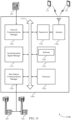
- FIG. 11 shows a diagram of a system 1100 including a device 1105 that supports synchronization signal transmission techniques for PAPR reduction in accordance with various aspects of the present disclosure.
- Device 1105 may be an example of or include the components of wireless device 805, wireless device 905, or a base station 105 as described with reference to FIGs. 1 , 8 and 9 .
- Device 1105 may include components for bi-directional voice and data communications including components for transmitting and receiving communications, including synchronization signal manager 1115, processor 1120, memory 1125, software 1130, transceiver 1135, antenna 1140, network communications manager 1145, and base station communications manager 1150. These components may be in electronic communication via one or more busses ( e.g., bus 1110).
- Device 1105 may communicate wirelessly with one or more UEs 115.
- Processor 1120 may include an intelligent hardware device, (e.g., a general-purpose processor, a DSP, a central processing unit (CPU), a microcontroller, an ASIC, an FPGA, a programmable logic device, a discrete gate or transistor logic component, a discrete hardware component, or any combination thereof).
- processor 1120 may be configured to operate a memory array using a memory controller.
- a memory controller may be integrated into processor 1120.
- Processor 1120 may be configured to execute computer-readable instructions stored in a memory to perform various functions (e.g., functions or tasks supporting synchronization signal transmission techniques for PAPR reduction).
- Memory 1125 may include random access memory (RAM) and read only memory (ROM).
- RAM random access memory
- ROM read only memory
- the memory 1125 may store computer-readable, computer-executable software 1130 including instructions that, when executed, cause the processor to perform various functions described herein.
- the memory 1125 may contain, among other things, a basic input/output system (BIOS) which may control basic hardware and/or software operation such as the interaction with peripheral components or devices.
- BIOS basic input/output system
- Software 1130 may include code to implement aspects of the present disclosure, including code to support synchronization signal transmission techniques for PAPR reduction.
- Software 1130 may be stored in a non-transitory computer-readable medium such as system memory or other memory. In some cases, the software 1130 may not be directly executable by the processor but may cause a computer ( e.g., when compiled and executed) to perform functions described herein.
- Transceiver 1135 may communicate bi-directionally, via one or more antennas, wired, or wireless links as described above.
- the transceiver 1135 may represent a wireless transceiver and may communicate bi-directionally with another wireless transceiver.
- the transceiver 1135 may also include a modem to modulate the packets and provide the modulated packets to the antennas for transmission, and to demodulate packets received from the antennas.
- the wireless device may include a single antenna 1140. However, in some cases the device may have more than one antenna 1140, which may be capable of concurrently transmitting or receiving multiple wireless transmissions.
- Network communications manager 1145 may manage communications with the core network ( e.g., via one or more wired backhaul links). For example, the network communications manager 1145 may manage the transfer of data communications for client devices, such as one or more UEs 115.
- Network communications manager 1145 and/or at least some of its various sub-components may be implemented in hardware, software executed by a processor, firmware, or any combination thereof. If implemented in software executed by a processor, the functions of the network communications manager 1145 and/or at least some of its various sub-components may be executed by a general-purpose processor, a DSP, an ASIC, a FPGA or other programmable logic device, discrete gate or transistor logic, discrete hardware components, or any combination thereof designed to perform the functions described in the present disclosure.
- the network communications manager 1145 and/or at least some of its various sub-components may be physically located at various positions, including being distributed such that portions of functions are implemented at different physical locations by one or more physical devices.
- network communications manager 1145 and/or at least some of its various sub-components may be a separate and distinct component in accordance with various aspects of the present disclosure.
- network communications manager 1145 and/or at least some of its various sub-components may be combined with one or more other hardware components, including but not limited to a receiver, a transmitter, a transceiver, one or more other components described in the present disclosure, or a combination thereof in accordance with various aspects of the present disclosure.
- Base station communications manager 1150 may manage communications with other base stations 105, and may include a controller or scheduler for controlling communications with UEs 115 in cooperation with other base stations 105. For example, the base station communications manager 1150 may coordinate scheduling for transmissions to UEs 115 for various interference mitigation techniques such as beamforming or joint transmission. In some examples, base station communications manager 1150 may provide an X2 interface within an LTE/LTE-A wireless communication network technology to provide communication between base stations 105.
- Base station communications manager 1150 and/or at least some of its various sub-components may be implemented in hardware, software executed by a processor, firmware, or any combination thereof. If implemented in software executed by a processor, the functions of the base station communications manager 1150 and/or at least some of its various sub-components may be executed by a general-purpose processor, DSP, an ASIC, a FPGA or other programmable logic device, discrete gate or transistor logic, discrete hardware components, or any combination thereof designed to perform the functions described in the present disclosure.
- the base station communications manager 1150 and/or at least some of its various sub-components may be physically located at various positions, including being distributed such that portions of functions are implemented at different physical locations by one or more physical devices.
- base station communications manager 1150 and/or at least some of its various sub-components may be a separate and distinct component in accordance with various aspects of the present disclosure.
- base station communications manager 1150 and/or at least some of its various sub-components may be combined with one or more other hardware components, including but not limited to a receiver, a transmitter, a transceiver, one or more other components described in the present disclosure, or a combination thereof in accordance with various aspects of the present disclosure.
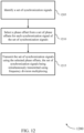
- FIG. 12 shows a flowchart illustrating a method 1200 for synchronization signal transmission techniques for PAPR reduction in accordance with various aspects of the present disclosure.
- the operations of method 1200 may be implemented by a base station 105 or its components as described herein.
- the operations of method 1200 may be performed by a synchronization signal manager as described with reference to FIGs. 8 through 11 .
- a base station 105 may execute a set of codes to control the functional elements of the device to perform the functions described below. Additionally or alternatively, the base station 105 may perform aspects the functions described below using special-purpose hardware.
- the base station 105 may identify a set of synchronization signals.
- the operations of block 1205 may be performed according to the methods described with reference to FIGs. 1 through 7 . In certain examples, aspects of the operations of block 1205 may be performed by a synchronization signal component as described with reference to FIGs. 8 through 11 .
- the base station 105 may select a phase offset from a set of phase offsets for each synchronization signal of the set of synchronization signals.
- the operations of block 1210 may be performed according to the methods described with reference to FIGs. 1 through 7 . In certain examples, aspects of the operations of block 1210 may be performed by a phase offset component as described with reference to FIGs. 8 through 11 .
- the base station 105 may transmit the set of synchronization signals using the selected phase offsets, the set of synchronization signals being simultaneously transmitted using frequency division multiplexing.
- the operations of block 1215 may be performed according to the methods described with reference to FIGs. 1 through 7 . In certain examples, aspects of the operations of block 1215 may be performed by a component carrier manager as described with reference to FIGs. 8 through 11 .
- FIG. 13 shows a flowchart illustrating a method 1300 for synchronization signal transmission techniques for PAPR reduction in accordance with various aspects of the present disclosure.
- the operations of method 1300 may be implemented by a base station 105 or its components as described herein.
- the operations of method 1300 may be performed by a synchronization signal manager as described with reference to FIGs. 8 through 11 .
- a base station 105 may execute a set of codes to control the functional elements of the device to perform the functions described below. Additionally or alternatively, the base station 105 may perform aspects the functions described below using special-purpose hardware.
- the base station 105 may identify a set of synchronization signals.
- the operations of block 1305 may be performed according to the methods described with reference to FIGs. 1 through 7 . In certain examples, aspects of the operations of block 1305 may be performed by a synchronization signal component as described with reference to FIGs. 8 through 11 .
- the base station 105 may select a phase offset from a set of phase offsets for each synchronization signal of the set of synchronization signals.
- the base station 105 may use various techniques to select the phase offset. For instance, at block 1310 the base station may optionally select the phase offset by applying a phase ramp across the synchronization signals each associated with different component carriers of a set of component carriers.
- the operations of block 1310 may be performed according to the methods described with reference to FIGs. 1 through 7 . In certain examples, aspects of the operations of block 1310 may be performed by a phase offset component as described with reference to FIGs. 8 through 11 .
- the base station 105 may optionally select the phase offset by applying a short Zadoff-Chu sequence or a short M sequence across the different component carriers of the set of component carriers.
- the operations of block 1315 may be performed according to the methods described with reference to FIGs. 1 through 7 . In certain examples, aspects of the operations of block 1315 may be performed by a phase offset component as described with reference to FIGs. 8 through 11 .
- the base station 105 may optionally select the phase offset by applying an extended Zadoff-Chu sequence or an extended M sequence across the different component carriers of the set of component carriers at block 1320.
- the operations of block 1320 may be performed according to the methods described with reference to FIGs. 1 through 7 . In certain examples, aspects of the operations of block 1320 may be performed by a phase offset component as described with reference to FIGs. 8 through 11 .
- the base station 105 may transmit the set of synchronization signals using the selected phase offsets, the set of synchronization signals being simultaneously transmitted using frequency division multiplexing.
- the operations of block 1325 may be performed according to the methods described with reference to FIGs. 1 through 7 . In certain examples, aspects of the operations of block 1325 may be performed by a component carrier manager as described with reference to FIGs. 8 through 11 .
- FIG. 14 shows a flowchart illustrating a method 1400 for synchronization signal transmission techniques for PAPR reduction in accordance with various aspects of the present disclosure.
- the operations of method 1400 may be implemented by a base station 105 or its components as described herein.
- the operations of method 1400 may be performed by a synchronization signal manager as described with reference to FIGs. 8 through 11 .
- a base station 105 may execute a set of codes to control the functional elements of the device to perform the functions described below. Additionally or alternatively, the base station 105 may perform aspects the functions described below using special-purpose hardware.
- the base station 105 may identify a set of synchronization signals.
- the operations of block 1405 may be performed according to the methods described with reference to FIGs. 1 through 7 . In certain examples, aspects of the operations of block 1405 may be performed by a synchronization signal component as described with reference to FIGs. 8 through 11 .
- the base station 105 may identify a set of phase offsets based at least in part on a number of component carriers of a set of component carriers, or a sequence of the synchronization signals associated with different component carriers of the set of component carriers, or both.
- the operations of block 1410 may be performed according to the methods described with reference to FIGs. 1 through 7 . In certain examples, aspects of the operations of block 1410 may be performed by a phase offset component as described with reference to FIGs. 8 through 11 .
- the base station 105 may select a phase offset from a set of phase offsets for each synchronization signal.
- the operations of block 1415 may be performed according to the methods described with reference to FIGs. 1 through 7 . In certain examples, aspects of the operations of block 1415 may be performed by a phase offset component as described with reference to FIGs. 8 through 11 .
- the base station 105 may transmit the set of synchronization signals using the selected phase offsets, the set of synchronization signals being simultaneously transmitted using frequency division multiplexing.
- the operations of block 1420 may be performed according to the methods described with reference to FIGs. 1 through 7 . In certain examples, aspects of the operations of block 1420 may be performed by a component carrier manager as described with reference to FIGs. 8 through 11 .
- FIG. 15 shows a flowchart illustrating a method 1500 for synchronization signal transmission techniques for PAPR reduction in accordance with various aspects of the present disclosure.
- the operations of method 1500 may be implemented by a base station 105 or its components as described herein.
- the operations of method 1500 may be performed by a synchronization signal manager as described with reference to FIGs. 8 through 11 .
- a base station 105 may execute a set of codes to control the functional elements of the device to perform the functions described below. Additionally or alternatively, the base station 105 may perform aspects the functions described below using special-purpose hardware.
- the base station 105 may identify a set of synchronization signal blocks.
- the operations of block 1505 may be performed according to the methods described with reference to FIGs. 1 through 7 . In certain examples, aspects of the operations of block 1505 may be performed by a synchronization signal component as described with reference to FIGs. 8 through 11 .
- the base station 105 may transmit each synchronization signal block of the set of synchronization signal blocks, each synchronization signal block being transmitted on one or more component carriers of a set of component carriers or transmitted simultaneously on a wideband carrier.
- the operations of block 1510 may be performed according to the methods described with reference to FIGs. 1 through 7 . In certain examples, aspects of the operations of block 1510 may be performed by a component carrier manager as described with reference to FIGs. 8 through 11 .
- FIG. 16 shows a flowchart illustrating a method 1600 for synchronization signal transmission techniques for PAPR reduction in accordance with various aspects of the present disclosure.
- the operations of method 1600 may be implemented by a base station 105 or its components as described herein.
- the operations of method 1600 may be performed by a synchronization signal manager as described with reference to FIGs. 8 through 11 .
- a base station 105 may execute a set of codes to control the functional elements of the device to perform the functions described below. Additionally or alternatively, the base station 105 may perform aspects the functions described below using special-purpose hardware.
- the base station 105 may identify a set of synchronization signal blocks.
- the operations of block 1605 may be performed according to the methods described with reference to FIGs. 1 through 7 . In certain examples, aspects of the operations of block 1605 may be performed by a synchronization signal component as described with reference to FIGs. 8 through 11 .
- the base station 105 may identify a first transmit power greater than a second transmit power, the second transmit power associated with transmitting a synchronization signal block over multiple component carriers of a set of component carriers from a same antenna port.
- the operations of block 1610 may be performed according to the methods described with reference to FIGs. 1 through 7 . In certain examples, aspects of the operations of block 1610 may be performed by a transmit power component as described with reference to FIGs. 8 through 11 .
- the base station 105 may transmit each synchronization signal block of the set of synchronization signal blocks, each synchronization signal block being transmitted on one or more component carriers of a set of component carriers or transmitted simultaneously on a wideband carrier, where transmitting each synchronization signal block includes using the first transmit power and using a first beam configuration having a first width greater than a second width of a second beam configuration.
- the first beam configuration is based at least in part on a plurality of beam directions.
- the second beam configuration may be associated with transmitting a synchronization signal block over multiple component carriers of the set of component carriers from a same antenna port.
- the operations of block 1615 may be performed according to the methods described with reference to FIGs. 1 through 7 . In certain examples, aspects of the operations of block 1615 may be performed by a component carrier manager as described with reference to FIGs. 8 through 11 .
- aspects from two or more of the methods 1200, 1300, 1400, 1500, or 1600 described with reference to FIGs. 12 through 16 may be combined. It should be noted that the methods 1200, 1300, 1400, 1500, and 1600 are just example implementations, and that the operations of the methods 1200, 1300, 1400, 1500, or 1600 may be rearranged or otherwise modified such that other implementations are possible.
- CDMA code division multiple access
- TDMA time division multiple access
- FDMA frequency division multiple access
- OFDMA orthogonal frequency division multiple access
- SC-FDMA single carrier frequency division multiple access
- CDMA2000 covers IS-2000, IS-95, and IS-856 standards.
- IS-2000 Releases may be commonly referred to as CDMA2000 1X, 1X, etc.
- IS-856 (TIA-856) is commonly referred to as CDMA2000 1xEV-DO, High Rate Packet Data (HRPD), etc.
- UTRA includes Wideband CDMA (WCDMA) and other variants of CDMA.
- WCDMA Wideband CDMA
- a time division multiple access (TDMA) system may implement a radio technology such as Global System for Mobile Communications (GSM).
- GSM Global System for Mobile Communications
- An orthogonal frequency division multiple access (OFDMA) system may implement a radio technology such as Ultra Mobile Broadband (UMB), Evolved UTRA (E-UTRA), Institute of Electrical and Electronics Engineers (IEEE) 802.11 (Wi-Fi), IEEE 802.16 (WiMAX), IEEE 802.20, Flash-OFDM, etc.
- UMB Ultra Mobile Broadband
- E-UTRA Evolved UTRA
- IEEE Institute of Electrical and Electronics Engineers
- Wi-Fi Wi-Fi
- WiMAX IEEE 802.16
- IEEE 802.20 WiMAX
- Flash-OFDM Flash-OFDM
- UTRA, E-UTRA, UMTS, LTE, LTE-A, NR, and Global System for Mobile communications are described in documents from the organization named "3rd Generation Partnership Project” (3GPP).
- CDMA2000 and UMB are described in documents from an organization named "3rd Generation Partnership Project 2" (3GPP2).
- the techniques described herein may be used for the systems and radio technologies mentioned above as well as other systems and radio technologies. While aspects an LTE or an NR system may be described for purposes of example, and LTE or NR terminology may be used in much of the description, the techniques described herein are applicable beyond LTE or NR applications.
- the term evolved node B may be generally used to describe the base stations.
- the wireless communications system or systems described herein may include a heterogeneous LTE/LTE-A or NR network in which different types of evolved node B (eNBs) provide coverage for various geographical regions.
- eNBs evolved node B
- each eNB, next generation NodeB (gNB), or base station may provide communication coverage for a macro cell, a small cell, or other types of cell.
- gNB next generation NodeB
- the term "cell” may be used to describe a base station, a carrier or component carrier associated with a base station, or a coverage area (e.g., sector, etc .) of a carrier or base station, depending on context.
- Base stations may include or may be referred to by those skilled in the art as a base transceiver station, a radio base station, an access point, a radio transceiver, a NodeB, eNB, gNB, Home NodeB, a Home eNodeB, or some other suitable terminology.
- the non-transitory computer-readable media may comprise RAM, ROM, electrically erasable programmable read only memory (EEPROM), compact disk (CD) ROM or other optical disk storage, magnetic disk storage or other magnetic storage devices, or any other non-transitory medium that can be used to carry or store desired program code means in the form of instructions or data structures and that can be accessed by a general-purpose or special-purpose computer, or a general-purpose or special-purpose processor.
- EEPROM electrically erasable programmable read only memory
- CD compact disk
- magnetic disk storage or other magnetic storage devices or any other non-transitory medium that can be used to carry or store desired program code means in the form of instructions or data
- any connection is properly termed a computer-readable medium.
- the software is transmitted from a website, server, or other remote source using a coaxial cable, fiber optic cable, twisted pair, digital subscriber line (DSL), or wireless technologies such as infrared, radio, and microwave
- the coaxial cable, fiber optic cable, twisted pair, digital subscriber line (DSL), or wireless technologies such as infrared, radio, and microwave are included in the definition of medium.
- Disk and disc include CD, laser disc, optical disc, digital versatile disc (DVD), floppy disk and Blu-ray disc where disks usually reproduce data magnetically, while discs reproduce data optically with lasers. Combinations of the above are also included within the scope of computer-readable media.
- Information and signals described herein may be represented using any of a variety of different technologies and techniques.
- data, instructions, commands, information, signals, bits, symbols, and chips that may be referenced throughout the above description may be represented by voltages, currents, electromagnetic waves, magnetic fields or particles, optical fields or particles, or any combination thereof.
- a general-purpose processor may be a microprocessor, but in the alternative, the processor may be any conventional processor, controller, microcontroller, or state machine.
- a processor may also be implemented as a combination of computing devices (e.g., a combination of a DSP and a microprocessor, multiple microprocessors, one or more microprocessors in conjunction with a DSP core, or any other such configuration).
- the functions described herein may be implemented in hardware, software executed by a processor, firmware, or any combination thereof. If implemented in software executed by a processor, the functions may be stored on or transmitted over as one or more instructions or code on a computer-readable medium. Other examples and implementations are within the scope of the disclosure and appended claims. For example, due to the nature of software, functions described above can be implemented using software executed by a processor, hardware, firmware, hardwiring, or combinations of any of these. Features implementing functions may also be physically located at various positions, including being distributed such that portions of functions are implemented at different physical locations.
- any connection is properly termed a computer-readable medium.
- the software is transmitted from a website, server, or other remote source using a coaxial cable, fiber optic cable, twisted pair, digital subscriber line (DSL), or wireless technologies such as infrared, radio, and microwave
- the coaxial cable, fiber optic cable, twisted pair, digital subscriber line (DSL), or wireless technologies such as infrared, radio, and microwave are included in the definition of medium.
- Disk and disc include CD, laser disc, optical disc, digital versatile disc (DVD), floppy disk and Blu-ray disc where disks usually reproduce data magnetically, while discs reproduce data optically with lasers. Combinations of the above are also included within the scope of computer-readable media.
Landscapes
- Engineering & Computer Science (AREA)
- Signal Processing (AREA)
- Computer Networks & Wireless Communication (AREA)
- Mobile Radio Communication Systems (AREA)
- Digital Transmission Methods That Use Modulated Carrier Waves (AREA)
- Transmitters (AREA)
Priority Applications (1)
| Application Number | Priority Date | Filing Date | Title |
|---|---|---|---|
| EP24210636.7A EP4478672A3 (en) | 2016-11-14 | 2017-09-25 | Synchronization signal transmission techniques for peak-to-average power ratio reduction |
Applications Claiming Priority (3)
| Application Number | Priority Date | Filing Date | Title |
|---|---|---|---|
| US201662421630P | 2016-11-14 | 2016-11-14 | |
| US15/713,225 US10938545B2 (en) | 2016-11-14 | 2017-09-22 | Synchronization signal transmission techniques for peak-to-average power ratio reduction |
| PCT/US2017/053240 WO2018089116A1 (en) | 2016-11-14 | 2017-09-25 | Synchronization signal transmission techniques for peak-to-average power ratio reduction |
Related Child Applications (2)
| Application Number | Title | Priority Date | Filing Date |
|---|---|---|---|
| EP24210636.7A Division EP4478672A3 (en) | 2016-11-14 | 2017-09-25 | Synchronization signal transmission techniques for peak-to-average power ratio reduction |
| EP24210636.7A Division-Into EP4478672A3 (en) | 2016-11-14 | 2017-09-25 | Synchronization signal transmission techniques for peak-to-average power ratio reduction |
Publications (2)
| Publication Number | Publication Date |
|---|---|
| EP3539243A1 EP3539243A1 (en) | 2019-09-18 |
| EP3539243B1 true EP3539243B1 (en) | 2024-12-18 |
Family
ID=62108863
Family Applications (2)
| Application Number | Title | Priority Date | Filing Date |
|---|---|---|---|
| EP17784096.4A Active EP3539243B1 (en) | 2016-11-14 | 2017-09-25 | Synchronization signal transmission techniques for peak-to-average power ratio reduction |
| EP24210636.7A Pending EP4478672A3 (en) | 2016-11-14 | 2017-09-25 | Synchronization signal transmission techniques for peak-to-average power ratio reduction |
Family Applications After (1)
| Application Number | Title | Priority Date | Filing Date |
|---|---|---|---|
| EP24210636.7A Pending EP4478672A3 (en) | 2016-11-14 | 2017-09-25 | Synchronization signal transmission techniques for peak-to-average power ratio reduction |
Country Status (8)
| Country | Link |
|---|---|
| US (2) | US10938545B2 (enExample) |
| EP (2) | EP3539243B1 (enExample) |
| JP (2) | JP7130640B2 (enExample) |
| KR (3) | KR20240152418A (enExample) |
| CN (2) | CN114900280B (enExample) |
| BR (1) | BR112019009468A2 (enExample) |
| TW (2) | TWI777668B (enExample) |
| WO (1) | WO2018089116A1 (enExample) |
Families Citing this family (22)
| Publication number | Priority date | Publication date | Assignee | Title |
|---|---|---|---|---|
| US11109398B2 (en) * | 2016-08-10 | 2021-08-31 | Lg Electronics Inc. | Signal transmission method and device using variable resource structure |
| WO2018174587A1 (en) * | 2017-03-23 | 2018-09-27 | Samsung Electronics Co., Ltd. | Method and apparatus for pbch transmission in a multi-beam based system |
| US10701647B2 (en) * | 2017-03-24 | 2020-06-30 | Electronics And Telecommunications Research Institute | Operation method of communication node transmitting synchronization signal in communication network |
| US11184878B2 (en) * | 2017-05-05 | 2021-11-23 | Beijing Xiaomi Mobile Software Co., Ltd. | Signal transmission method, signal transmission apparatus, electronic device and computer-readable storage medium |
| EP3661081B1 (en) * | 2017-07-28 | 2022-04-13 | LG Electronics Inc. | Method for transmitting and receiving synchronization signal block and apparatus therefor |
| WO2019066569A1 (en) * | 2017-09-28 | 2019-04-04 | Lg Electronics Inc. | METHOD AND APPARATUS FOR SUPPORTING MULTIPLE CARRIERS IN A WIRELESS COMMUNICATION SYSTEM |
| EP3692753A1 (en) | 2017-10-02 | 2020-08-12 | Sony Corporation | Method and device for synchronization and measurement in a radio communication system |
| US11398874B2 (en) * | 2017-11-29 | 2022-07-26 | Lg Electronics Inc. | Method and apparatus for measuring signal quality in wireless communication system |
| CN111641982B (zh) * | 2018-01-19 | 2022-01-18 | Oppo广东移动通信有限公司 | 小区重选方法及装置 |
| US11147104B2 (en) * | 2018-05-11 | 2021-10-12 | Apple Inc. | PRACH resource selection |
| CN108781425B (zh) * | 2018-06-21 | 2021-01-22 | 北京小米移动软件有限公司 | 传输同步信号的方法及装置 |
| US10993236B2 (en) * | 2018-12-05 | 2021-04-27 | Qualcomm Incorporated | Synchronization signal measurement for beam detection |
| WO2020197311A1 (ko) * | 2019-03-28 | 2020-10-01 | 엘지전자 주식회사 | 무선 통신 시스템에서 신호를 송수신하는 방법 및 장치 |
| WO2021213659A1 (en) * | 2020-04-23 | 2021-10-28 | Telefonaktiebolaget Lm Ericsson (Publ) | Grouping in series-connected radios |
| US11451425B2 (en) | 2020-05-01 | 2022-09-20 | Qualcomm Incorporated | Peak-to-average power ratio (PAPR) reduction techniques |
| US12040927B2 (en) | 2020-05-01 | 2024-07-16 | Qualcomm Incorporated | Peak-to-average power ratio (PAPR) reduction techniques |
| WO2022081319A2 (en) * | 2020-10-16 | 2022-04-21 | Qualcomm Incorporated | Phase characteristic capability reporting for sounding reference signal (srs) stitching |
| US11831384B2 (en) * | 2020-10-23 | 2023-11-28 | Qualcomm Incorporated | Joint panel parameter update |
| US20220141675A1 (en) * | 2020-11-05 | 2022-05-05 | Qualcomm Incorporated | Reference signal transmissions for multi-beam operation |
| EP4264898A1 (en) * | 2020-12-18 | 2023-10-25 | Telefonaktiebolaget LM Ericsson (publ) | Transmitting synchronisation signals on multiple carriers |
| CN115250524A (zh) * | 2021-04-25 | 2022-10-28 | 维沃移动通信有限公司 | 同步资源配置方法、装置、用户设备及存储介质 |
| US11924006B2 (en) * | 2021-11-17 | 2024-03-05 | T-Mobile Innovations Llc | Enhanced method to do channel estimation in a multiple input multiple output based cellular radio technology by leveraging radio power reception level at per antenna element |
Family Cites Families (41)
| Publication number | Priority date | Publication date | Assignee | Title |
|---|---|---|---|---|
| KR20040106847A (ko) * | 2003-06-11 | 2004-12-18 | 삼성전자주식회사 | 다중 반송파 수신 시스템 및 그의 신호 처리 방법 |
| US8711811B2 (en) * | 2008-06-19 | 2014-04-29 | Telefonaktiebolaget L M Ericsson (Publ) | Identifying multi-component carrier cells |
| WO2010042885A1 (en) * | 2008-10-10 | 2010-04-15 | Powerwave Technologies, Inc. | Crest factor reduction for ofdm communications systems by transmitting phase shifted resource blocks |
| KR101581956B1 (ko) * | 2008-10-22 | 2016-01-04 | 엘지전자 주식회사 | 무선통신 시스템에서 신호 전송 방법 및 장치 |
| US8948208B2 (en) * | 2008-11-07 | 2015-02-03 | Qualcomm Incorporated | Conveying information through phase offset on PSS relative to DL-RS |
| EP2211515B1 (en) * | 2009-01-22 | 2016-05-25 | Samsung Electronics Co., Ltd. | Apparatus and method for transmitting and receiving uplink sounding signal in broadband wireless communication system |
| CN101510867A (zh) * | 2009-03-17 | 2009-08-19 | 中兴通讯股份有限公司 | 同步信号的发送方法和装置 |
| CN101540978B (zh) * | 2009-04-27 | 2013-09-11 | 中兴通讯股份有限公司 | 下行分量载波标识方法、同步下行分量载波上报方法与装置 |
| JP5084951B2 (ja) * | 2009-04-28 | 2012-11-28 | 三菱電機株式会社 | 移動体通信システム |
| CN103096329A (zh) * | 2011-11-02 | 2013-05-08 | 中兴通讯股份有限公司 | 一种载波配置方法及系统 |
| US9591597B2 (en) * | 2011-12-02 | 2017-03-07 | Lg Electronics Inc. | Method for indicating control channel in wireless access system, and base station and user equipment for the same |
| US9247542B2 (en) * | 2012-01-31 | 2016-01-26 | Apple Inc. | Methods and apparatus for efficient spectral usage in extensible carrier deployments |
| US8874103B2 (en) * | 2012-05-11 | 2014-10-28 | Intel Corporation | Determining proximity of user equipment for device-to-device communication |
| US9473229B2 (en) | 2012-10-05 | 2016-10-18 | Samsung Electronics Co., Ltd. | High-throughput beamforming MIMO receiver for millimeter wave communication and method |
| KR101882953B1 (ko) | 2013-04-18 | 2018-07-27 | 한국전자통신연구원 | 무선 프레임 구성 방법 및 이를 이용하는 장치 |
| US9893852B2 (en) * | 2013-08-19 | 2018-02-13 | Qualcomm Incorporated | Coordination of clear channel assessment across component carriers in an unlicensed or shared spectrum |
| EP3066875B1 (en) * | 2013-11-08 | 2019-10-30 | Nokia Solutions and Networks Oy | Synchronization signal design for device to device operation |
| US10348541B2 (en) * | 2013-11-27 | 2019-07-09 | Telefonaktiebolaget Lm Ericsson (Publ) | Sending and detecting synchronization signals and an associated information message |
| EP3075187B1 (en) * | 2013-11-27 | 2022-11-02 | Apple Inc. | Mechanisms for co-existence of lte-u network with itself and with other technologies |
| US9924368B2 (en) * | 2013-12-11 | 2018-03-20 | Qualcomm Incorporated | Apparatus and methods for cellular communications over unused unlicenced spectrum |
| US9730174B2 (en) * | 2014-02-27 | 2017-08-08 | Lg Electronics Inc. | Method of transmitting a scheduling assignment signal for device-to-device communication in a wireless communication system, and an apparatus thereof |
| EP3130189A1 (en) * | 2014-04-09 | 2017-02-15 | IDAC Holdings, Inc. | Mmw physical layer downlink channel scheduling and control signaling |
| US9986518B2 (en) * | 2014-07-03 | 2018-05-29 | Qualcomm Incorporated | Transmission and reception of synchronization signals over an unlicensed radio frequency spectrum band |
| US9602322B2 (en) * | 2014-08-01 | 2017-03-21 | Qualcomm Incorporated | Transmission and reception of discovery signals over a radio frequency spectrum band |
| WO2016147994A1 (ja) | 2015-03-13 | 2016-09-22 | シャープ株式会社 | 端末装置および通信方法 |
| JP6513877B2 (ja) * | 2015-07-24 | 2019-05-15 | インテル コーポレイション | 狭帯域lte配置のための同期信号及びチャネル構造 |
| US10893520B2 (en) * | 2015-08-26 | 2021-01-12 | Qualcomm Incorporated | Downlink and synchronization techniques for narrowband wireless communications |
| WO2017039374A1 (en) * | 2015-09-02 | 2017-03-09 | Lg Electronics Inc. | Method and apparatus for performing random access procedure in nb-iot carrier in wireless communication system |
| US10277270B2 (en) * | 2015-12-08 | 2019-04-30 | Lg Electronics Inc. | Method for transmitting uplink signal in a wireless communication system and apparatus for the same |
| CN106961689B (zh) * | 2016-01-11 | 2019-04-30 | 北京展讯高科通信技术有限公司 | 参考信号的接收方法及装置 |
| US10536940B2 (en) * | 2016-01-12 | 2020-01-14 | Nokia Solutions And Networks Oy | Discovery signal block mapping |
| KR102765392B1 (ko) * | 2016-02-03 | 2025-02-11 | 엘지전자 주식회사 | 협대역 동기신호 송수신 방법 및 이를 위한 장치 |
| US10887143B2 (en) * | 2016-05-06 | 2021-01-05 | Samsung Electronics Co., Ltd. | Method and apparatus for initial access in wireless communication systems |
| WO2017213420A1 (ko) * | 2016-06-07 | 2017-12-14 | 엘지전자(주) | 무선 통신 시스템에서 순환 전치에 대한 정보를 획득하는 방법 및 이를 위한 장치 |
| US11063717B2 (en) * | 2016-08-08 | 2021-07-13 | Lg Electronics Inc. | Channel state information transmitting method and user equipment, and channel state information receiving method and base station |
| CN109478969B (zh) * | 2016-08-10 | 2021-11-16 | Lg 电子株式会社 | 用于在移动通信系统中收发广播信道信号的方法和装置 |
| TWI665925B (zh) * | 2016-10-11 | 2019-07-11 | 聯發科技股份有限公司 | 用於行動通訊中的同步信號塊處理方法及設備 |
| JP7046824B2 (ja) * | 2016-11-02 | 2022-04-04 | 株式会社Nttドコモ | ユーザ端末及び無線通信方法 |
| US10389567B2 (en) * | 2016-11-03 | 2019-08-20 | Samsung Electronics Co., Ltd. | Method and apparatus for synchronization signal design |
| US10980066B2 (en) * | 2016-11-06 | 2021-04-13 | Lg Electronics Inc. | Method and user equipment for transmitting random access signals, and method and base station for receiving random access signals |
| US10548079B2 (en) * | 2017-02-06 | 2020-01-28 | Qualcomm Incorporated | Tracking reference signal for new radio |
-
2017
- 2017-09-22 US US15/713,225 patent/US10938545B2/en active Active
- 2017-09-25 KR KR1020247033463A patent/KR20240152418A/ko active Pending
- 2017-09-25 KR KR1020197013617A patent/KR102613110B1/ko active Active
- 2017-09-25 KR KR1020237013200A patent/KR20230056799A/ko not_active Ceased
- 2017-09-25 WO PCT/US2017/053240 patent/WO2018089116A1/en not_active Ceased
- 2017-09-25 JP JP2019524175A patent/JP7130640B2/ja active Active
- 2017-09-25 BR BR112019009468A patent/BR112019009468A2/pt unknown
- 2017-09-25 CN CN202210660980.2A patent/CN114900280B/zh active Active
- 2017-09-25 TW TW110125778A patent/TWI777668B/zh active
- 2017-09-25 CN CN201780069601.XA patent/CN109923827B/zh active Active
- 2017-09-25 EP EP17784096.4A patent/EP3539243B1/en active Active
- 2017-09-25 EP EP24210636.7A patent/EP4478672A3/en active Pending
- 2017-09-25 TW TW106132760A patent/TWI764932B/zh active
-
2021
- 2021-02-03 US US17/166,655 patent/US20210167940A1/en active Pending
-
2022
- 2022-08-24 JP JP2022133278A patent/JP7646607B2/ja active Active
Also Published As
| Publication number | Publication date |
|---|---|
| JP2022166292A (ja) | 2022-11-01 |
| TWI777668B (zh) | 2022-09-11 |
| EP4478672A2 (en) | 2024-12-18 |
| CN109923827A (zh) | 2019-06-21 |
| KR20240152418A (ko) | 2024-10-21 |
| TWI764932B (zh) | 2022-05-21 |
| BR112019009468A2 (pt) | 2019-07-30 |
| KR20230056799A (ko) | 2023-04-27 |
| KR20190078586A (ko) | 2019-07-04 |
| WO2018089116A1 (en) | 2018-05-17 |
| TW202207752A (zh) | 2022-02-16 |
| KR102613110B1 (ko) | 2023-12-13 |
| JP7646607B2 (ja) | 2025-03-17 |
| JP7130640B2 (ja) | 2022-09-05 |
| CN114900280B (zh) | 2024-05-17 |
| EP3539243A1 (en) | 2019-09-18 |
| US10938545B2 (en) | 2021-03-02 |
| JP2019537896A (ja) | 2019-12-26 |
| US20180139036A1 (en) | 2018-05-17 |
| TW201818765A (zh) | 2018-05-16 |
| CN114900280A (zh) | 2022-08-12 |
| EP4478672A3 (en) | 2025-01-08 |
| US20210167940A1 (en) | 2021-06-03 |
| CN109923827B (zh) | 2022-05-27 |
Similar Documents
| Publication | Publication Date | Title |
|---|---|---|
| EP3539243B1 (en) | Synchronization signal transmission techniques for peak-to-average power ratio reduction | |
| US12225517B2 (en) | Data and control channels in synchronization bursts for millimeter wave new radio | |
| US10728897B2 (en) | Uplink resources for beam recovery | |
| US10700802B2 (en) | Variable length reference signaling for fast acquisition in shared spectrum | |
| US10505773B2 (en) | Association between synchronization signal beams and reference signal beams | |
| EP3659287B1 (en) | Techniques for extended cell discovery | |
| EP3539266B1 (en) | Synchronization signal design | |
| US10873938B2 (en) | Rate matching for broadcast channels | |
| EP3963789A1 (en) | Reference signal transmission techniques for random access messages |
Legal Events
| Date | Code | Title | Description |
|---|---|---|---|
| STAA | Information on the status of an ep patent application or granted ep patent |
Free format text: STATUS: UNKNOWN |
|
| STAA | Information on the status of an ep patent application or granted ep patent |
Free format text: STATUS: THE INTERNATIONAL PUBLICATION HAS BEEN MADE |
|
| PUAI | Public reference made under article 153(3) epc to a published international application that has entered the european phase |
Free format text: ORIGINAL CODE: 0009012 |
|
| STAA | Information on the status of an ep patent application or granted ep patent |
Free format text: STATUS: REQUEST FOR EXAMINATION WAS MADE |
|
| 17P | Request for examination filed |
Effective date: 20190329 |
|
| AK | Designated contracting states |
Kind code of ref document: A1 Designated state(s): AL AT BE BG CH CY CZ DE DK EE ES FI FR GB GR HR HU IE IS IT LI LT LU LV MC MK MT NL NO PL PT RO RS SE SI SK SM TR |
|
| AX | Request for extension of the european patent |
Extension state: BA ME |
|
| DAV | Request for validation of the european patent (deleted) | ||
| DAX | Request for extension of the european patent (deleted) | ||
| STAA | Information on the status of an ep patent application or granted ep patent |
Free format text: STATUS: EXAMINATION IS IN PROGRESS |
|
| 17Q | First examination report despatched |
Effective date: 20210525 |
|
| GRAP | Despatch of communication of intention to grant a patent |
Free format text: ORIGINAL CODE: EPIDOSNIGR1 |
|
| STAA | Information on the status of an ep patent application or granted ep patent |
Free format text: STATUS: GRANT OF PATENT IS INTENDED |
|
| INTG | Intention to grant announced |
Effective date: 20240712 |
|
| GRAS | Grant fee paid |
Free format text: ORIGINAL CODE: EPIDOSNIGR3 |
|
| GRAA | (expected) grant |
Free format text: ORIGINAL CODE: 0009210 |
|
| STAA | Information on the status of an ep patent application or granted ep patent |
Free format text: STATUS: THE PATENT HAS BEEN GRANTED |
|
| AK | Designated contracting states |
Kind code of ref document: B1 Designated state(s): AL AT BE BG CH CY CZ DE DK EE ES FI FR GB GR HR HU IE IS IT LI LT LU LV MC MK MT NL NO PL PT RO RS SE SI SK SM TR |
|
| REG | Reference to a national code |
Ref country code: GB Ref legal event code: FG4D |
|
| REG | Reference to a national code |
Ref country code: CH Ref legal event code: EP |
|
| REG | Reference to a national code |
Ref country code: DE Ref legal event code: R096 Ref document number: 602017086836 Country of ref document: DE |
|
| REG | Reference to a national code |
Ref country code: IE Ref legal event code: FG4D |
|
| REG | Reference to a national code |
Ref country code: LT Ref legal event code: MG9D |
|
| PG25 | Lapsed in a contracting state [announced via postgrant information from national office to epo] |
Ref country code: HR Free format text: LAPSE BECAUSE OF FAILURE TO SUBMIT A TRANSLATION OF THE DESCRIPTION OR TO PAY THE FEE WITHIN THE PRESCRIBED TIME-LIMIT Effective date: 20241218 |
|
| PG25 | Lapsed in a contracting state [announced via postgrant information from national office to epo] |
Ref country code: FI Free format text: LAPSE BECAUSE OF FAILURE TO SUBMIT A TRANSLATION OF THE DESCRIPTION OR TO PAY THE FEE WITHIN THE PRESCRIBED TIME-LIMIT Effective date: 20241218 |
|
| PG25 | Lapsed in a contracting state [announced via postgrant information from national office to epo] |
Ref country code: BG Free format text: LAPSE BECAUSE OF FAILURE TO SUBMIT A TRANSLATION OF THE DESCRIPTION OR TO PAY THE FEE WITHIN THE PRESCRIBED TIME-LIMIT Effective date: 20241218 |
|
| PG25 | Lapsed in a contracting state [announced via postgrant information from national office to epo] |
Ref country code: NO Free format text: LAPSE BECAUSE OF FAILURE TO SUBMIT A TRANSLATION OF THE DESCRIPTION OR TO PAY THE FEE WITHIN THE PRESCRIBED TIME-LIMIT Effective date: 20250318 |
|
| REG | Reference to a national code |
Ref country code: NL Ref legal event code: MP Effective date: 20241218 |
|
| PG25 | Lapsed in a contracting state [announced via postgrant information from national office to epo] |
Ref country code: LV Free format text: LAPSE BECAUSE OF FAILURE TO SUBMIT A TRANSLATION OF THE DESCRIPTION OR TO PAY THE FEE WITHIN THE PRESCRIBED TIME-LIMIT Effective date: 20241218 Ref country code: GR Free format text: LAPSE BECAUSE OF FAILURE TO SUBMIT A TRANSLATION OF THE DESCRIPTION OR TO PAY THE FEE WITHIN THE PRESCRIBED TIME-LIMIT Effective date: 20250319 |
|
| PG25 | Lapsed in a contracting state [announced via postgrant information from national office to epo] |
Ref country code: RS Free format text: LAPSE BECAUSE OF FAILURE TO SUBMIT A TRANSLATION OF THE DESCRIPTION OR TO PAY THE FEE WITHIN THE PRESCRIBED TIME-LIMIT Effective date: 20250318 |
|
| PG25 | Lapsed in a contracting state [announced via postgrant information from national office to epo] |
Ref country code: NL Free format text: LAPSE BECAUSE OF FAILURE TO SUBMIT A TRANSLATION OF THE DESCRIPTION OR TO PAY THE FEE WITHIN THE PRESCRIBED TIME-LIMIT Effective date: 20241218 |
|
| REG | Reference to a national code |
Ref country code: AT Ref legal event code: MK05 Ref document number: 1753109 Country of ref document: AT Kind code of ref document: T Effective date: 20241218 |
|
| PG25 | Lapsed in a contracting state [announced via postgrant information from national office to epo] |
Ref country code: SM Free format text: LAPSE BECAUSE OF FAILURE TO SUBMIT A TRANSLATION OF THE DESCRIPTION OR TO PAY THE FEE WITHIN THE PRESCRIBED TIME-LIMIT Effective date: 20241218 |
|
| PG25 | Lapsed in a contracting state [announced via postgrant information from national office to epo] |
Ref country code: PL Free format text: LAPSE BECAUSE OF FAILURE TO SUBMIT A TRANSLATION OF THE DESCRIPTION OR TO PAY THE FEE WITHIN THE PRESCRIBED TIME-LIMIT Effective date: 20241218 |
|
| PG25 | Lapsed in a contracting state [announced via postgrant information from national office to epo] |
Ref country code: ES Free format text: LAPSE BECAUSE OF FAILURE TO SUBMIT A TRANSLATION OF THE DESCRIPTION OR TO PAY THE FEE WITHIN THE PRESCRIBED TIME-LIMIT Effective date: 20241218 |
|
| PG25 | Lapsed in a contracting state [announced via postgrant information from national office to epo] |
Ref country code: IS Free format text: LAPSE BECAUSE OF FAILURE TO SUBMIT A TRANSLATION OF THE DESCRIPTION OR TO PAY THE FEE WITHIN THE PRESCRIBED TIME-LIMIT Effective date: 20250418 |
|
| PG25 | Lapsed in a contracting state [announced via postgrant information from national office to epo] |
Ref country code: PT Free format text: LAPSE BECAUSE OF FAILURE TO SUBMIT A TRANSLATION OF THE DESCRIPTION OR TO PAY THE FEE WITHIN THE PRESCRIBED TIME-LIMIT Effective date: 20250421 |
|
| PG25 | Lapsed in a contracting state [announced via postgrant information from national office to epo] |
Ref country code: EE Free format text: LAPSE BECAUSE OF FAILURE TO SUBMIT A TRANSLATION OF THE DESCRIPTION OR TO PAY THE FEE WITHIN THE PRESCRIBED TIME-LIMIT Effective date: 20241218 |
|
| PG25 | Lapsed in a contracting state [announced via postgrant information from national office to epo] |
Ref country code: RO Free format text: LAPSE BECAUSE OF FAILURE TO SUBMIT A TRANSLATION OF THE DESCRIPTION OR TO PAY THE FEE WITHIN THE PRESCRIBED TIME-LIMIT Effective date: 20241218 Ref country code: AT Free format text: LAPSE BECAUSE OF FAILURE TO SUBMIT A TRANSLATION OF THE DESCRIPTION OR TO PAY THE FEE WITHIN THE PRESCRIBED TIME-LIMIT Effective date: 20241218 |
|
| PG25 | Lapsed in a contracting state [announced via postgrant information from national office to epo] |
Ref country code: SK Free format text: LAPSE BECAUSE OF FAILURE TO SUBMIT A TRANSLATION OF THE DESCRIPTION OR TO PAY THE FEE WITHIN THE PRESCRIBED TIME-LIMIT Effective date: 20241218 |
|
| PG25 | Lapsed in a contracting state [announced via postgrant information from national office to epo] |
Ref country code: CZ Free format text: LAPSE BECAUSE OF FAILURE TO SUBMIT A TRANSLATION OF THE DESCRIPTION OR TO PAY THE FEE WITHIN THE PRESCRIBED TIME-LIMIT Effective date: 20241218 |
|
| PG25 | Lapsed in a contracting state [announced via postgrant information from national office to epo] |
Ref country code: IT Free format text: LAPSE BECAUSE OF FAILURE TO SUBMIT A TRANSLATION OF THE DESCRIPTION OR TO PAY THE FEE WITHIN THE PRESCRIBED TIME-LIMIT Effective date: 20241218 |
|
| PG25 | Lapsed in a contracting state [announced via postgrant information from national office to epo] |
Ref country code: SE Free format text: LAPSE BECAUSE OF FAILURE TO SUBMIT A TRANSLATION OF THE DESCRIPTION OR TO PAY THE FEE WITHIN THE PRESCRIBED TIME-LIMIT Effective date: 20241218 |
|
| REG | Reference to a national code |
Ref country code: DE Ref legal event code: R097 Ref document number: 602017086836 Country of ref document: DE |
|
| PG25 | Lapsed in a contracting state [announced via postgrant information from national office to epo] |
Ref country code: DK Free format text: LAPSE BECAUSE OF FAILURE TO SUBMIT A TRANSLATION OF THE DESCRIPTION OR TO PAY THE FEE WITHIN THE PRESCRIBED TIME-LIMIT Effective date: 20241218 |
|
| PGFP | Annual fee paid to national office [announced via postgrant information from national office to epo] |
Ref country code: DE Payment date: 20250808 Year of fee payment: 9 |
|
| PGFP | Annual fee paid to national office [announced via postgrant information from national office to epo] |
Ref country code: GB Payment date: 20250814 Year of fee payment: 9 |
|
| PGFP | Annual fee paid to national office [announced via postgrant information from national office to epo] |
Ref country code: FR Payment date: 20250808 Year of fee payment: 9 |
|
| PLBE | No opposition filed within time limit |
Free format text: ORIGINAL CODE: 0009261 |
|
| STAA | Information on the status of an ep patent application or granted ep patent |
Free format text: STATUS: NO OPPOSITION FILED WITHIN TIME LIMIT |
|
| 26N | No opposition filed |
Effective date: 20250919 |