EP3538857B1 - Unterbaugruppe eines drucksensors und herstellung - Google Patents
Unterbaugruppe eines drucksensors und herstellung Download PDFInfo
- Publication number
- EP3538857B1 EP3538857B1 EP17804482.2A EP17804482A EP3538857B1 EP 3538857 B1 EP3538857 B1 EP 3538857B1 EP 17804482 A EP17804482 A EP 17804482A EP 3538857 B1 EP3538857 B1 EP 3538857B1
- Authority
- EP
- European Patent Office
- Prior art keywords
- pressure
- fluid
- pressure sensor
- substrate
- differential pressure
- Prior art date
- Legal status (The legal status is an assumption and is not a legal conclusion. Google has not performed a legal analysis and makes no representation as to the accuracy of the status listed.)
- Active
Links
Images


Classifications
-
- G—PHYSICS
- G01—MEASURING; TESTING
- G01L—MEASURING FORCE, STRESS, TORQUE, WORK, MECHANICAL POWER, MECHANICAL EFFICIENCY, OR FLUID PRESSURE
- G01L9/00—Measuring steady of quasi-steady pressure of fluid or fluent solid material by electric or magnetic pressure-sensitive elements; Transmitting or indicating the displacement of mechanical pressure-sensitive elements, used to measure the steady or quasi-steady pressure of a fluid or fluent solid material, by electric or magnetic means
- G01L9/0041—Transmitting or indicating the displacement of flexible diaphragms
- G01L9/0051—Transmitting or indicating the displacement of flexible diaphragms using variations in ohmic resistance
- G01L9/0052—Transmitting or indicating the displacement of flexible diaphragms using variations in ohmic resistance of piezoresistive elements
- G01L9/0055—Transmitting or indicating the displacement of flexible diaphragms using variations in ohmic resistance of piezoresistive elements bonded on a diaphragm
-
- G—PHYSICS
- G01—MEASURING; TESTING
- G01L—MEASURING FORCE, STRESS, TORQUE, WORK, MECHANICAL POWER, MECHANICAL EFFICIENCY, OR FLUID PRESSURE
- G01L13/00—Devices or apparatus for measuring differences of two or more fluid pressure values
- G01L13/02—Devices or apparatus for measuring differences of two or more fluid pressure values using elastically-deformable members or pistons as sensing elements
- G01L13/025—Devices or apparatus for measuring differences of two or more fluid pressure values using elastically-deformable members or pistons as sensing elements using diaphragms
- G01L13/026—Devices or apparatus for measuring differences of two or more fluid pressure values using elastically-deformable members or pistons as sensing elements using diaphragms involving double diaphragm
-
- G—PHYSICS
- G01—MEASURING; TESTING
- G01L—MEASURING FORCE, STRESS, TORQUE, WORK, MECHANICAL POWER, MECHANICAL EFFICIENCY, OR FLUID PRESSURE
- G01L9/00—Measuring steady of quasi-steady pressure of fluid or fluent solid material by electric or magnetic pressure-sensitive elements; Transmitting or indicating the displacement of mechanical pressure-sensitive elements, used to measure the steady or quasi-steady pressure of a fluid or fluent solid material, by electric or magnetic means
- G01L9/0041—Transmitting or indicating the displacement of flexible diaphragms
- G01L9/0042—Constructional details associated with semiconductive diaphragm sensors, e.g. etching, or constructional details of non-semiconductive diaphragms
Definitions
- This application relates to sensors. More particularly, the application relates to semiconductor pressure sensors.
- Differential pressure sensors measure a difference in pressure between two isolated fluids or gasses.
- EP2189773A2 upon which the pre-characterising portion of the appended Claim 1 is based, discloses an example of a differential pressure sensor including a pressure sensor die that is housed within a package formed by upper and lower package members.
- EP1782029A1 or WO2006/023987A1 discloses another example of a pressure sensor that is housed within a package formed by upper and lower package members. When used in an environment which includes conductive or corrosive gasses or fluids, the sensor must be isolated from these harsh media in order to protect the sensor itself, as well as the electronic or electrical components attached thereto.
- Differential pressure sensors are harder to isolate from harsh media than gage or absolute pressure sensors due to the presence of two pressure sources being applied to opposing sides of the sensor. Therefore, both sides of the sensor must be isolated in some way or the sensor may be damaged.
- US6311561B1 and EP3048434A2 disclose examples of differential pressure sensors including means to isolate the sensor from harsh media.
- US7024937B2 discloses an example of an absolute or gauge pressure sensor including an internal housing component that covers a pressure sensing die and corresponding control circuit.
- the pressure-sensing die is formed from a semiconductor material such as silicon.
- the die is formed from a silicon wafer by methods such as dicing to produce a silicon structure, which is thinned to create a cavity and define an associated diaphragm.
- Piezoresistive elements are formed or placed at the surface of the diaphragm and are configured to exhibit resistance that is proportional to the strain placed on the thinned semiconductor material forming the diaphragm.
- a suitable package may include one or more input ports for receiving the media whose pressure is to be measured.
- the media being measured enters a first volume of the package which is isolated from the pressure-sensing die by a flexible membrane or diaphragm.
- the flexible membrane or diaphragm is formed from a material which can withstand any harsh effects related to the media whose pressure is being measured.
- the flexible membrane or diaphragm that contacts the measured media may comprise stainless steel.
- the flexible membrane or diaphragm is configured to flex when the pressure of the media under test exerts a force to the surface of the flexible membrane or diaphragm.
- the package may further define a second volume in contact with the flexible membrane or diaphragm opposite the first volume containing the media under test.
- the second volume is further in fluid contact with a pressure sensitive surface of the pressure-sensing diaphragm defined in the pressure-sensing die.
- the second volume is filled with a fluid that may safely contact the diaphragm and associated electrical connections of the pressure-sensing die.
- the second volume may be filled with silicon oil, which will not harm the semiconductor-based pressure-sensing die.
- the flexing of the flexible membrane or diaphragm exerts a force against the fluid contained in the second volume.
- This force which is representative of the pressure of the media under test, is transferred through the fluid in the second volume to the semiconductor diaphragm of the pressure-sensing die.
- the applied force causes flexing of the semiconductor diaphragm and the piezoresistive elements formed on the semiconductor diaphragm's surface.
- the strain on the piezoresistive elements cause their resistance to vary in proportion to the applied force due to the media pressure.
- An electrical circuit connected to the piezoresistive elements creates an electrical signal, based in part on the resistance value of the piezoresistive elements. Accordingly, the electrical signal is representative of the pressure of the media under test.
- Packaging of the pressure-sensing die increases the complexity of manufacturing pressure sensors which may be used in harsh environments. Furthermore, the package may have to be fabricated to adapt to a specific use. Therefore, pressure-sensing dies, along with their associated circuitry, are desired which can be easily fabricated and adapted for installation into a variety of packaging implementations.
- the present invention provides a differential pressure sensor according to Claim 1 of the appended claims.
- Optional features are defined in the dependent claims.
- Fluids may be liquid, such as oil or water, or fluids may refer to a gas, such as air or other gasses placed in communication with the sensor via sensing ports.
- the term fluid when used in this disclosure may refer to either a liquid or a gas or both. Further for the purposes of this disclosure, any state of matter which adapts its shape to the dimensions of its container may also be referred to by the term fluid.
- FIG. 1 is a cross-sectional view of a pressure sensor subassembly 100 suitable for use in a differential pressure sensor according to the present invention.
- Pressure sensor subassembly 100 is configured to detect pressure by way of a semiconductor pressure-sensing die 101.
- Pressure-sensing die 101 is thinned to form a thinned region defining a diaphragm 103.
- a surface of diaphragm 103 is doped to form piezoresistive elements (not shown) which exhibit electrical resistance that varies due to flexing of semiconductor diaphragm 103 when one or more pressures act thereon.
- Pressure-sensing die 101 may be configured to detect absolute pressure by applying a pressure under test to one surface of semiconductor diaphragm 103 and applying a reference pressure to another surface of semiconductor diaphragm 103 opposite the first surface. Similarly, pressure-sensing die 101 may be configured to detect a differential pressure between a first pressure and a second pressure. This is accomplished by applying the first pressure to a first surface of semiconductor diaphragm 103, while simultaneously applying a second pressure to a second surface of semiconductor diaphragm 103 opposite the first surface. Semiconductor diaphragm 103 will experience a force which is representative of the net pressure difference between the pressures applied to the first and second surfaces or sides of semiconductor diaphragm 103.
- the piezoresistive elements will exhibit a resistance representative of this net pressure difference applied to semiconductor diaphragm 103.
- Pressure-sensing die 101 is attached to a substrate 105 embodied, for example, as a printed circuit board (PCB).
- PCB printed circuit board
- Pressure-sensing die 101 is attached (e.g., via adhesive, solder or glass frit) to substrate 105 at attachment points 107, as known in the art.
- the piezoresistive elements of semiconductor diaphragm 103 are electrically connected to substrate 105 via bond wires 109 or bonded directly to pads formed on substrate 105 to pressure-sensing die 101 using bump or direct solder techniques, as known in the art.
- bond wires 109 are attached to an electrical path or trace 111 which is disposed on or in the surface of substrate 105.
- electrical path or trace 111 may be a combination of conductors formed on a surface of substrate 105 and conductive layers embedded in substrate 105. Electrically conductive trace 111 may be printed on the surface of substrate 105 using printing or etching techniques, as known in the art.
- Pressure sensor subassembly 100 includes processing circuitry 114 for processing electrical signals generated by the piezoresistive elements of pressure-sensing die 101.
- Processing circuitry 114 may include a microprocessor in communication with a memory, the microprocessor configured for processing instructions which may be stored in the memory.
- the memory may be incorporated in a chip along with the microprocessor, or the memory may be separate from the microprocessor and in electrical communication with the microprocessor through circuitry disposed on substrate 105.
- processing circuitry 114 may be implemented in an application specific integrated circuit (ASIC), a field programmable gate array (FPGA), or other device for processing electrical signals generated by pressure-sensing die 101.
- ASIC application specific integrated circuit
- FPGA field programmable gate array
- Processing circuit 114 is electrically connect to electrically conductive trace 111 and electrically conductive trace 115, each disposed on substrate 105. Processing circuit 114 may be configured to performed processing on signals produced by pressure-sensing die 101 and to produce processed output signals to an electrical contact pin of bond pad 117, which may be used for facilitating electrical connections to external components for further processing based on the output generated by pressure sensor subassembly 100.
- Pressure sensor subassembly 100 includes a housing 121 which defines a volume containing pressure-sensing die 101.
- Housing 121 may be formed from materials such as silicon or other semiconductor materials, glass, metal, plastic, ceramic as well as other suitable materials.
- An opening 123 is defined through housing 121 to provide fluid communication to an upper surface of semiconductor diaphragm 103 of pressure-sensing die 101. Opening 123 may comprise a diameter that is about equal to or greater than the diameter or length of semiconductor diaphragm 103.
- a second opening 119 may be defined through substrate 105 to provide fluid communication to the a lower surface of semiconductor diaphragm 103.
- Pressure sensor subassembly 100 may include a bonding agent or sealant 125 which is applied to the upper surface of housing 121 for surrounding aperture 123, and to the lower surface of substrate 105 for surrounding aperture 119.
- a seal may be formed at the upper surface of the housing 121 and the underside of substrate 105 using an O-ring seal (126, 128, as shown in FIG. 3B and FIG. 3C ). Sealant 125 (or O-ring 126, 128) allows pressure sensor subassembly 100 to be inserted into and sealed with respect to a separately-fabricated sensor housing.
- Sensor housing 121 may include other pressure sensor components, such as fluid ports associated with apertures 123, 119, oil-filled isolated volumes which prevent harsh media whose pressure is being measured from coming into contact with the pressure-sensing die 101 and the electrical components (e.g. piezoresistive elements, bond wires, electrically conductive traces) of pressure sensor subassembly 100.
- fluid ports associated with apertures 123, 119 oil-filled isolated volumes which prevent harsh media whose pressure is being measured from coming into contact with the pressure-sensing die 101 and the electrical components (e.g. piezoresistive elements, bond wires, electrically conductive traces) of pressure sensor subassembly 100.
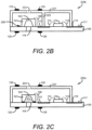
- FIG. 2A is a cross-sectional view of a pressure-sensing subassembly 200a suitable for use in a differential pressure sensor according to the present invention, including an isolated volume containing circuit components.
- Pressure-sensing subassembly 200a is configured to detect pressure using a semiconductor pressure-sensing die 101.
- a portion of semiconductor pressure-sensing die 101 is thinned to define a pressure-sensitive diaphragm 103.
- Piezoresistive elements (not shown) are arranged or formed at one or more surfaces of diaphragm 103. When a pressure is exerted on a surface of diaphragm 103, diaphragm 103 deflects and produces a strain on the piezoresistive elements.
- the piezoresistive elements exhibit an electrical resistance which varies with the amount of this deflection.
- the piezoresistive elements are electrically connected to circuitry of subassembly 200a via a bond wire 109 and an electrically conductive trace 111.
- the piezoresistive elements are further connected to a control circuit 114 via electrically conductive trace 111 and a bond wire 113.
- Control circuit 114 may be configured as an integrated circuit chip which controls and processes signals generated from the electrical circuitry including the piezoresistive elements at the surface of diaphragm 103.
- Control circuit 114 may provide electrical signals to circuits external to subassembly 200a via bond wire 113 connected to another electrically conductive trace 115 which is in electrical contact with output terminals via bond pads 117.
- pressure-sensing die 101 is bonded to a substrate 105 at attachment points 107 using adhesive, anodic bonding or soldering techniques as known in the art.
- a housing 221 is provided which covers the pressure-sensing die 101 and control circuit 114 and is attached to substrate 105 via adhesive, solder or glass frit, by way of example one.
- pressure-sensing die 101 and control circuit 114 are separated by a wall 225 which provides a fluid-tight barrier between pressure-sensing die 101 and control circuit 114. This design minimizes the amount of fill volume and isolates control circuit 114 from the pressure transmitting fluid.
- FIG. 2C illustrates a housing 121 enclosing both pressure-sensing die 101 and control circuit 114 in common volume or interior space. This embodiment minimizes the size of subassembly 200c. However, during use the pressure-sensing die 101 and control circuit 114 of subassembly 200c would be submerged in a pressure-transmitting fluid.
- a first aperture 119 is provided through substrate 105 which allows a fluid to enter aperture 119 and come into fluid contact with a bottom surface of diaphragm 103. According to one embodiment, aperture 119 is configured to have a diameter that is substantially equal or greater to the diameter of diaphragm 103.
- a second aperture 223 is defined through housing 221 which allows a fluid to come into fluid communication with an upper surface of diaphragm 103.
- Pressure-sensing subassembly 200 may act as a differential pressure sensor wherein a first fluid at a first pressure is introduced through aperture 223 and comes into fluid communication with the upper surface of diaphragm 103, while at the same time, a second fluid at a second pressure is introduced through aperture 119 and comes in fluid communication with the lower surface of diaphragm 103.
- the first and second pressures are applied to opposing surfaces of diaphragm 103 and may cause a deflection of diaphragm 103 which is representative of a difference in pressure between the first pressure and the second pressure.
- Pressure-sensing subassembly 200a may include a bonding agent or sealant 125 or O-ring-type seal ( FIG. 3B , 126, 128), both at the upper surface of housing 221 and generally surrounding aperture 223 and at the lower surface of substrate 105 surrounding aperture 119. Sealant 125 allows pressure-sensing subassembly 200 to be inserted into and sealed with respect to a separately-fabricated sensor housing. Referring to FIG. 2B , pressure-sensing die 101 may be anodically bonded directly to substrate 105 at location 208.
- Sensor housing 221 may include other pressure sensor components, such as fluid ports associated with apertures 223 and 119, oil-filled isolated volumes which prevent harsh media whose pressure is being measured from coming into contact with the pressure-sensing die 101 and the electrical components (e.g. piezoresistive elements, bond wires, electrically conductive traces) of pressure-sensing subassembly 200.
- fluid ports associated with apertures 223 and 119 oil-filled isolated volumes which prevent harsh media whose pressure is being measured from coming into contact with the pressure-sensing die 101 and the electrical components (e.g. piezoresistive elements, bond wires, electrically conductive traces) of pressure-sensing subassembly 200.
- FIG. 3A is a cross-sectional view of a differential pressure sensor 300a including a pressure sensor subassembly 100 according to an embodiment of the present invention.
- Pressure sensor subassembly 100 is configured as a modular component insertable into a pressure sensor package.
- the pressure sensor package illustrated in FIG. 3A includes two housing members 350, 360.
- Pressure sensor subassembly 100 is inserted between housing member 350 and housing member 360.
- Pressure sensor subassembly 100 includes a semiconductor pressure-sensing die 101.
- Pressure-sensing die 101 is thinned at a portion of the die to form a thin pressure-sensitive diaphragm 103.
- Piezoresistive elements (not shown) are formed or arranged at a surface of diaphragm 103.
- Substrate 105 includes an opening or aperture defined through the substrate 105 allowing access to the underside of diaphragm 103.
- the aperture defined in substrate 105 may be substantially aligned with the lower surface of diaphragm 103 and may have a diameter which is substantially equal to or greater than the diameter of diaphragm 103.
- a control circuit 114 is disposed on substrate 105 and performs processing of electrical signals generated by the varying resistance of the piezoresistive elements when diaphragm 103 experiences forces created by pressure applied to the surfaces of diaphragm 103.
- the piezoresistive elements may be electrically connected to control circuit 114 via bond wires (109, shown in FIG. 1 ) and electrically conductive traces (111, shown in FIG. 1 ) defined at or on a surface of substrate 105.
- Control circuit 114 may be configured as an integrated circuit chip, for example, control circuit 114 may be an ASIC.
- One or more bond pads 117 may provide electrical connection to circuitry external to the pressure sensor subassembly 100.
- Bond pads 117 are electrically connected to control circuit 114 via bond wires and electrically conductive traces (113, 115, respectively, as shown in FIG. 1 ). Bond pads 117 may be configured as an output terminal, including a conductive pin, blade, socket, or the like for creating an electrical connection with a complimentary electrical connector from an external circuit or system.
- Pressure sensor subassembly includes a housing (121, shown in FIG. 1 ), which contains pressure-sensing die 101.
- An aperture (123, shown if FIG. 1 ) is defined in housing 121 and allows fluid access to the upper surface of sensitive diaphragm 103.
- a seal, such as sealing material 125 is disposed on the upper surface of the housing 121 and generally surrounds aperture 123.
- Sealing material 125 of FIG. 3A may be an adhesive, such as glue, or may comprise solder which may be used to form a fluid-tight joint between housing 121 of pressure sensor assembly 100 and a body 340 of pressure sensor upper member 350.
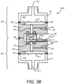
- an O-ring type seal 126, 128 may be used in place of sealant material 125 of FIG. 3A .
- Bond or sealing material 125 (or O-ring 128) is also applied to the lower surface of substrate 105, surrounding opening or aperture 119 defined in substrate 105. Sealing material 125 may be used to for a fluid-tight seal between the lower surface of substrate 105 of pressure sensor subassembly 100 and body 330 of pressure lower sensor member 360.
- Pressure sensor upper member 350 includes an outer wall 301 which is configured to form a fluid inlet port 303.
- Fluid inlet port 303 may include a threaded surface, which may be connected to a threaded conduit carrying a first fluid whose pressure is to be measured by pressure sensor 300.
- a flexible diaphragm 307 forms a wall between outer wall 301 and body 340. The outer edges of flexible diaphragm 307 are positioned between outer wall 301 and body 340 and sealed by welds 302.
- Outer wall 301, body 340 and flexible diaphragm 307 comprise materials which are resistant to damage caused by exposure to harsh media which may be introduced to fluid inlet port 303.
- outer wall 301, body 340 and flexible diaphragm 307 may comprise stainless steel.
- Body 340 includes a chamber 321 extending from one end of body 340 to the other, an oil-fill tube 323 which extends from an outer surface of body 340 to chamber 321.
- Oil-fill tube 323 allows an oil or other fluid to be introduced into and fill chamber 321 forming an oil-filled volume 309 between flexible diaphragm 307 and body 340.
- the oil or fluid introduced via oil-fill tube 323 also travels through chamber 321 and enters aperture 123 defined in housing 121 of pressure sensor subassembly 100. The oil or fluid enters housing 121 and comes into fluid communication with the upper surface of semiconductor pressure-sensing die 101.
- Seal 125 allows the oil or fluid to enter the aperture 123 in housing 121 and provides a fluid-tight seal, maintaining the oil or fluid at pressure inside pressure sensor 300.
- Oil-fill tube 323 may be sealed when chamber 321 and oil-filled volume 309 are filled by a welding ball 325 or other sealing method such as crimping and the like.
- the oil may simply be trapped inside the pressure sensor 300c by introducing the oil prior to the attachment of pressure-sensing die 101 or subassembly 200a to the housing.
- FIG. 3C omits filter tube 323 and welding ball 325.
- 3C provides a lower cost sensor which does not require welded balls or drilled holes for introducing a transmitting fluid after fabrication.
- the pressure-sensing die sub-assembly 100 is inserted between body 330 and body 340, which are mated together. Housing bodies 330, 340 are welded together, while O-rings 126 and 128 are positioned as shown to create a seal between the pressure-sensing die sub-assembly 100 and housing bodies 330, 340.
- Fluid-filled volumes 309, 319 may be filled with oil or other transmitting fluid and sealed by welding flexible diaphragm 307 and flexible diaphragm 317 in place against housing bodies 340 and 330, respectively.
- Flexible diaphragms 307, 317 may be welded in place by an appropriate connection technique such as a resistance weld, by way of example.
- Pressure sensor lower member 360 is configured similarly to pressure sensor upper member 350 and includes an outer wall 311 which is configured to form a fluid inlet port 313.
- Fluid inlet port 313 may include a threaded surface, which may be connected to a threaded conduit carrying a second fluid whose pressure is to be measured by the pressure sensor 300.
- a flexible diaphragm 317 forms a wall between outer wall 311 and body 330. The outer edges of flexible diaphragm 317 are positioned between outer wall 311 and body 330 and sealed by welds 312.
- Outer wall 311, body 330 and flexible diaphragm 317 comprise materials which are resistant to damage caused by exposure to harsh media which may be introduced to fluid inlet port 313.
- outer wall 311, body 330 and flexible diaphragm 317 may comprise stainless steel.
- Body 330 includes a chamber 331 extending from one end of body 330 to the other, an oil-fill tube 333 which extends from an outer surface of body 330 to chamber 331.
- Oil-fill tube 333 allows an oil or other fluid to be introduced into and to fill chamber 331 forming an oil-filled volume 319 between flexible diaphragm 317 and body 330.
- the oil or fluid introduced via oil-fill tube 333 also travels through chamber 331 and enters aperture 119 defined in substrate 105 of pressure sensor subassembly 100.
- the oil or fluid enters aperture 119 and comes into fluid communication with the lower surface of sensitive diaphragm 103 of semiconductor pressure-sensing die 101.
- Oil-fill tube 333 may be sealed once chamber 331 and oil-filled volume 319 are filled by a welding ball 335 or other sealing method such as crimping and the like.
- the oil may simply be trapped inside the pressure sensor 300c by introducing the oil prior to attachment of the pressure-sensing die 101 or the subassembly 200a attachment to the housing.
- FIG. 3C omits filter tube 333 and welding ball 335.
- differential pressure sensor 300d in which fluid inlet port 303 and fluid inlet port 313 are arranged such that input fluids at differential pressures may be introduced to differential pressure sensor 300d from one side of the sensor.
- Differential pressure sensor 300d provides simple access to both fluid inlet port 303 for receiving a first fluid at a first pressure, and second fluid inlet port 313 for receiving a second fluid at a second pressure.
- Differential pressure sensor 300d may be flush mounted and easily connected to a pair of fluid inputs. By way of non-limiting example, differential pressure sensor 300d may be flush mounted to an engine manifold.
- Differential pressure sensor 300d may measure a difference in pressure between the input and the output of a valve, such as an emission gas recirculation (EGR) valve.
- EGR emission gas recirculation
- the pressure at the input of the EGR valve may be introduced to fluid input port 303, while the pressure at the output of the EGR valve may be introduced to fluid input port 313.
- Differential pressure sensor 300d will thereby measure a differential pressure across the EGR valve.
- the measured value of the differential pressure across the valve may be transmitted to control circuity providing master control of an engine's systems.
- the location of fluid input port 303 and fluid input port 313 allow for easy attachment of the fluid inputs, through a modular plug or the like, which is attached to hoses leading from the ends of the EGR valve.
- Other components, such as valves, vacuum sensors, filters and the like may also be adapted for connection to differential pressure sensor 300d.
- Pressure sensor upper member 350 and pressure sensor lower member 360 may be mated together with subassembly 100 positioned therebetween. A joint formed between pressure sensor upper member 350 and pressure sensor lower member 360 is sealed by a weld 345. Pressure sensor lower member 360 may be sealed from the lower surface of substrate 105 by sealing material 125 or O-ring 128. Pressure sensor upper member 350 may be bonded to housing 121 of pressure sensor subassembly 100 by sealing material 125 or O-ring 126. The resulting structure defines differential pressure sensor 300a, 300b, 300c, 300d which includes the pressure sensor housing comprising upper member 350 and lower member 360 which accommodate modular pressure sensor subassembly 100.
- differential pressure sensors operate by attaching a first fluid source at a first pressure to fluid inlet port 303 and a second fluid source at a second pressure to fluid inlet port 313.
- First fluid source introduces a fluid, which may be a gas, at the first pressure via fluid inlet port 303 to fill volume 305.
- Volume 305 includes flexible diaphragm 307 as one of its walls. Therefore, the first fluid comes into contact with flexible diaphragm 307.
- First fluid is at a first pressure which exerts a force on flexible diaphragm 307. The force causes flexible diaphragm 307 to deflect and exert a force on the oil or fluid in oil-filled volume 309. Force is transmitted undiminished through the oil or fluid in oil-filled volume 309, through chamber 321 and onto the upper surface of diaphragm 103 of semiconductor pressure-sensing die 101.
- Second fluid source introduces a fluid, which may be a gas, at the second pressure via fluid inlet port 313 to fill volume 315.
- Volume 315 includes flexible diaphragm 317 as one of its walls. Therefore, the second fluid comes into contact with flexible diaphragm 317.
- Second fluid is at a second pressure which exerts a force on flexible diaphragm 317. The force causes flexible diaphragm 317 to deflect and exert a force on the oil or fluid in oil-filled volume 319. Force is transmitted undiminished through the oil or fluid in oil-filled volume 319, through chamber 331 and onto the lower surface of diaphragm 103 of semiconductor pressure-sensing die 101.
- the first fluid at a first pressure is applied to the upper surface of sensitive diaphragm 103 while the second fluid at a second pressure is simultaneously applied to the lower surface of sensitive diaphragm 103.
- the differential pressure between the first pressure and the second pressure determines the amount of deflection of diaphragm 103, and as a result, the resistance value of the piezoresistive elements formed at or on the surface of diaphragm 103.
- Control circuit 114 is configured to produce an electrical signal that varies with the resistance value of the piezoresistive elements.
- Control circuit 114 may include a processor for processing an electrical signal produced by the resistance value of the piezoresistive elements to produce an output signal which is electrically communicated to bond pads 117.
- the processed electrical signal contains information representative of the differential pressure applied to the upper and lower surfaces of diaphragm 103.
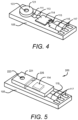
- FIG. 4 is an isometric view of the pressure-sensing subassembly of FIG. 1 .
- Substrate 105 may be a ceramic substrate, a printed circuit board or other suitable material.
- Substrate 105 supports a semiconductor pressure-sensing die (101, shown in FIG. 1 ) which is enclosed by a housing 121.
- Housing 121 has an aperture 123 defined therethrough for providing fluid communication between a fluid under test and the upper surface of a sensitive diaphragm (103, FIG. 1 ) of pressure-sensing die 101.
- Housing 121 is configured as a circular or cylindrical volume which surrounds the pressure-sensing die 101.
- Piezoresistive elements defined at the surface of diaphragm 103 are connected to electrically conductive traces 111 which are disposed at the surface of substrate 105.
- a control circuit 114 which may be configured as an ASIC, is connected to electrically conductive traces 111 and 115 by bond wires 113.
- Electrically conductive traces 115 are electrically connected to bond pads 117 which may be electrically connected to other circuitry external to pressure-sensing subassembly 100.
- FIG. 5 is an isometric view of the pressure-sensing subassembly including an isolated volume containing circuit components of FIG. 2 .
- Substrate 105 may be a ceramic substrate, a printed circuit board or other suitable material.
- Substrate 105 supports a semiconductor pressure-sensing die (101, shown in FIG. 2 ) which is enclosed by a housing 221.
- Housing 221 has an aperture 223 defined therethrough for providing fluid communication between a fluid under test and the upper surface of a sensitive diaphragm (103, FIG. 2 ) of pressure-sensing die 101.
- Housing 221 is configured as a rectangular volume which surrounds the pressure-sensing die 101 and control circuit 114.
- a dividing wall 225 separates pressure-sensing die 101 from control circuit 114.
- Piezoresistive elements defined at the surface of diaphragm 103 are connected to electrically conductive traces which are disposed at the surface of substrate 105.
- a control circuit 114 which may be configured as an ASIC, is connected to electrically conductive traces 115. Electrically conductive traces 115 are electrically connected to bond pads 117 which may be electrically connected to other circuitry external to pressure-sensing subassembly 200.
Landscapes
- Physics & Mathematics (AREA)
- General Physics & Mathematics (AREA)
- Chemical & Material Sciences (AREA)
- Analytical Chemistry (AREA)
- Measuring Fluid Pressure (AREA)
Claims (14)
- Differenzdrucksensor (300), der Folgendes umfasst:ein erstes Sensorgehäuseelement (350) mit einem ersten Fluideinlass (303) zur Aufnahme eines ersten Fluids mit einem ersten Druck;ein zweites Sensorgehäuseelement (360) mit einem zweiten Fluideinlass (313) zur Aufnahme eines zweiten Fluids mit einem zweiten Druck; undeine Druckmessunterbaugruppe (100) mit einem Substrat (105) und einem an dem Substrat (105) angebrachten Halbleiter-Druckmesschip (101), wobei der Halbleiter-Druckmesschip (101) eine empfindliche Membran (103) mit einer Oberseite und einer Unterseite und mindestens ein piezoresistives Element aufweist, das an der Unterseite und/oder der Oberseite der empfindlichen Membran (103) ausgebildet ist, wobei durch das Substrat (105) eine erste Öffnung (119) definiert ist, die im Wesentlichen mit der Unterseite der empfindlichen Membran (103) ausgerichtet ist, wobei die Druckmessunterbaugruppe (100) zum Einsetzen in den Differenzdrucksensor (300) konfiguriert ist, so dass nach dem Einsetzen der erste Fluideinlass (303) in Fluidverbindung mit der Oberseite der empfindlichen Membran (103) steht und der zweite Fluideinlass (313) in Fluidverbindung mit der Unterseite der empfindlichen Membran (103) steht;dadurch gekennzeichnet, dass die Druckmessunterbaugruppe (100) ferner eine an dem Substrat (105) angebrachte und elektrisch mit dem mindestens einen piezoresistiven Element verbundene Steuerschaltung (114) und ein an dem Substrat (105) angebrachtes Gehäuse (121) umfasst, wobei das Gehäuse (121) den Halbleiter-Druckmesschip (101) enthält und eine zweite Öffnung (123) durch es definiert ist, um eine Fluidverbindung mit der Oberseite der empfindlichen Membran (103) herzustellen.
- Differenzdrucksensor (300) nach Anspruch 1, wobei die Druckmessunterbaugruppe (100) ferner Dichtungsmaterial (125) umfasst, das auf einer Oberfläche des Gehäuses (121) um die zweite Öffnung (123) herum und auf einer Unterseite des Substrats (105) um die erste Öffnung (119) herum angeordnet ist, wobei das Dichtungsmaterial (125) eine fluiddichte Abdichtung zwischen dem Gehäuse (121) und dem ersten Sensorgehäuseelement (350) und zwischen der Unterseite des Substrats (105) und dem zweiten Sensorgehäuseelement (360) bereitstellt.
- Differenzdrucksensor (300) nach Anspruch 2, wobei das Dichtungsmaterial (125) ein Klebstoff ist.
- Differenzdrucksensor (300) nach Anspruch 2, wobei das Dichtungsmaterial (125) ein Lot ist.
- Differenzdrucksensor (300) nach Anspruch 2, wobei das Dichtungsmaterial (125) ein Elastomer oder Gummi ist, wie z.B. eine O-Ring-Dichtung.
- Differenzdrucksensor (300) nach Anspruch 1, wobei die Steuerschaltung (114) als anwendungsspezifische integrierte Schaltung konfiguriert ist.
- Differenzdrucksensor (300) nach Anspruch 1, wobei das erste Sensorgehäuseelement (350) mit dem ersten Fluideinlass (303) ferner Folgendes umfasst:eine Außenwand (301), die den ersten Fluideinlass (303) definiert und ferner ein erstes Volumen (305) zur Aufnahme des ersten Fluids bei dem ersten Druck definiert;eine erste flexible Membran (307), die eine Wand des ersten Volumens (305) zur Aufnahme des ersten Fluids mit dem ersten Druck definiert; undeinen ersten Körper (340), der eine erste Kammer (321) enthält, wobei die erste flexible Membran (307) zwischen der den ersten Fluideinlass (303) definierenden Außenwand (301) und dem ersten Körper (340) positioniert ist, wobei ein zweites Volumen (309) zwischen der ersten flexiblen Membran (307) und der ersten Kammer (321) definiert ist, wobei das zweite Volumen (309) zum Füllen mit einem Öl oder Fluid konfiguriert ist, das keine Beschädigung des Halbleiter-Druckmesschips (101) verursacht.
- Differenzdrucksensor (300) nach Anspruch 7, wobei das zweite Sensorgehäuseelement (360) mit dem zweiten Fluideinlass (313) ferner Folgendes umfasst:eine Außenwand (311), die den zweiten Fluideinlass (313) definiert und ferner ein drittes Volumen (315) zur Aufnahme des zweiten Fluids bei dem zweiten Druck definiert;eine zweite flexible Membran (317), die eine Wand des dritten Volumens (315) zur Aufnahme des zweiten Fluids mit dem zweiten Druck definiert; undeinen zweiten Körper (330), der eine zweite Kammer (331) enthält, wobei die zweite flexible Membran (317) zwischen der den zweiten Fluideinlass (313) definierenden Außenwand (311) und dem zweiten Körper (330) angeordnet ist, wobei ein viertes Volumen (319) zwischen der zweiten flexiblen Membran (317) und der zweiten Kammer (331) definiert ist, wobei das vierte Volumen (319) zum Füllen mit einem Öl oder Fluid konfiguriert ist, das keine Beschädigung des Halbleiter-Druckmesschips (101) verursacht.
- Differenzdrucksensor (300) nach Anspruch 8, wobei die den ersten und zweiten Fluideinlass (303, 313) definierenden Außenwände (301, 311), die erste und zweite flexible Membran (307, 317) und der erste und zweite Körper (340, 330) ein Material umfassen, das gegen Beschädigung durch ein raues Medium beständig ist.
- Differenzdrucksensor (300) nach Anspruch 9, wobei die den ersten und zweiten Fluideinlass (303, 313) definierenden Außenwände (301, 311), die erste und zweite flexible Membran (307, 317) und der erste und zweite Körper (340, 330) Edelstahl umfassen.
- Differenzdrucksensor (300) nach Anspruch 1, der ferner Folgendes umfasst:eine elektrisch leitende Spur (111), die auf der Oberfläche und/oder in Schichten unter der Oberfläche des Substrats (105) definiert ist, wobei die elektrisch leitende Spur (111) mit dem mindestens einen piezoresistiven Element über mindestens einen Bonddraht (109) elektrisch verbunden ist und mit der Steuerschaltung (114) elektrisch verbunden ist;mindestens ein Bondpad (117), das auf dem Substrat (105) angeordnet und mit der Steuerschaltung (114) elektrisch verbunden ist;eine erste Dichtung (125) auf einer Oberseite des Gehäuses (121) um die zweite Öffnung (123) herum; undeine zweite Dichtung (125) auf einer Unterseite des Substrats (105) um die erste Öffnung (119) herum.
- Differenzdrucksensor (300) nach Anspruch 11, wobei das Substrat (105) ein Glassubstrat umfasst.
- Differenzdrucksensor (300) nach Anspruch 11, der mindestens einen elektrisch leitenden Ausgangsstift umfasst, der mit dem mindestens einen Bondpad (117) elektrisch verbunden ist, um eine externe elektrische Verbindung mit der Druckmessunterbaugruppe (100) herzustellen.
- Differenzdrucksensor (300) nach Anspruch 11, wobei das Gehäuse (221) ferner zum Umgeben der Steuerschaltung (114) konfiguriert ist und eine Trennwand (225) zwischen dem Halbleiter-Druckmesschip (101) und der Steuerschaltung (114) umfasst.
Applications Claiming Priority (2)
| Application Number | Priority Date | Filing Date | Title |
|---|---|---|---|
| US15/349,699 US10466125B2 (en) | 2016-11-11 | 2016-11-11 | Pressure sensor sub assembly and fabrication |
| PCT/EP2017/078957 WO2018087332A2 (en) | 2016-11-11 | 2017-11-10 | Pressure sensor sub assembly and fabrication |
Publications (2)
| Publication Number | Publication Date |
|---|---|
| EP3538857A2 EP3538857A2 (de) | 2019-09-18 |
| EP3538857B1 true EP3538857B1 (de) | 2024-08-14 |
Family
ID=60473499
Family Applications (1)
| Application Number | Title | Priority Date | Filing Date |
|---|---|---|---|
| EP17804482.2A Active EP3538857B1 (de) | 2016-11-11 | 2017-11-10 | Unterbaugruppe eines drucksensors und herstellung |
Country Status (4)
| Country | Link |
|---|---|
| US (1) | US10466125B2 (de) |
| EP (1) | EP3538857B1 (de) |
| CN (1) | CN109952498A (de) |
| WO (1) | WO2018087332A2 (de) |
Families Citing this family (11)
| Publication number | Priority date | Publication date | Assignee | Title |
|---|---|---|---|---|
| NL2016557B1 (en) * | 2016-04-06 | 2017-10-17 | Fugro Eng B V | Pressure measurement device. |
| US10689248B2 (en) * | 2017-03-16 | 2020-06-23 | Advanced Semiconductor Engineering, Inc. | Semiconductor device package and method of manufacturing the same |
| IT201900019169A1 (it) * | 2019-10-17 | 2021-04-17 | St Microelectronics Srl | Interruttore impermeabile azionabile da un fluido quale aria e utilizzabile in particolare per l'attivazione di un apparecchio inalatore, quale una sigaretta elettronica |
| JP7319182B2 (ja) * | 2019-12-12 | 2023-08-01 | アズビル株式会社 | 差圧計 |
| CN111487006B (zh) * | 2020-04-16 | 2021-07-20 | 南京高华科技股份有限公司 | 基于应力隔离结构的微差压传感器 |
| WO2022030176A1 (ja) * | 2020-08-03 | 2022-02-10 | 株式会社村田製作所 | 圧力センサ用チップ、圧力センサ及びそれらの製造方法 |
| US11506557B2 (en) * | 2020-10-07 | 2022-11-22 | Honywell International Inc. | Differential pressure sensor and method of using the same |
| CN112903176B (zh) * | 2021-03-30 | 2025-06-03 | 明晶芯晟(成都)科技有限责任公司 | 基于封装基板的阵列式压力测量装置 |
| US11585714B2 (en) * | 2021-06-30 | 2023-02-21 | Kulite Semiconductor Products, Inc. | Oil fill transducer with rubber disc for dynamic protection |
| CN115979500B (zh) * | 2023-03-17 | 2023-06-13 | 成都凯天电子股份有限公司 | 一种双气压腔芯体、压力扫描阀及制备方法 |
| US20250076141A1 (en) * | 2023-09-01 | 2025-03-06 | Te Connectivity Solutions Gmbh | Sensor Having a Package with a Sensor Die |
Citations (1)
| Publication number | Priority date | Publication date | Assignee | Title |
|---|---|---|---|---|
| US7024937B2 (en) * | 2003-12-03 | 2006-04-11 | Honeywell International Inc. | Isolated pressure transducer |
Family Cites Families (22)
| Publication number | Priority date | Publication date | Assignee | Title |
|---|---|---|---|---|
| US5184107A (en) * | 1991-01-28 | 1993-02-02 | Honeywell, Inc. | Piezoresistive pressure transducer with a conductive elastomeric seal |
| US5186055A (en) * | 1991-06-03 | 1993-02-16 | Eaton Corporation | Hermetic mounting system for a pressure transducer |
| US6023978A (en) | 1996-07-10 | 2000-02-15 | Honeywell Data Instruments, Inc. | Pressure transducer with error compensation from cross-coupling outputs of two sensors |
| US5684253A (en) * | 1997-01-08 | 1997-11-04 | Honeywell Inc. | Differential pressure sensor with stress reducing pressure balancing means |
| US6311561B1 (en) | 1997-12-22 | 2001-11-06 | Rosemount Aerospace Inc. | Media compatible pressure sensor |
| US6255728B1 (en) * | 1999-01-15 | 2001-07-03 | Maxim Integrated Products, Inc. | Rigid encapsulation package for semiconductor devices |
| US6543291B1 (en) * | 2000-01-06 | 2003-04-08 | Kulite Semiconductor Products, Inc. | Wet-to-wet pressure sensing assembly |
| JP2003315193A (ja) * | 2002-04-24 | 2003-11-06 | Denso Corp | 圧力センサ |
| US7077008B2 (en) | 2004-07-02 | 2006-07-18 | Honeywell International Inc. | Differential pressure measurement using backside sensing and a single ASIC |
| ITMI20070099A1 (it) * | 2007-01-24 | 2008-07-25 | St Microelectronics Srl | Dispositivo elettronico comprendente dispositivi sensori differenziali mems e substrati bucati |
| US8297125B2 (en) * | 2008-05-23 | 2012-10-30 | Honeywell International Inc. | Media isolated differential pressure sensor with cap |
| US7992441B2 (en) * | 2008-07-31 | 2011-08-09 | Sensata Technologies, Inc. | Pressure sensor for measuring pressure in a medium |
| US8230745B2 (en) | 2008-11-19 | 2012-07-31 | Honeywell International Inc. | Wet/wet differential pressure sensor based on microelectronic packaging process |
| IT1394791B1 (it) * | 2009-05-20 | 2012-07-13 | Metallux Sa | Sensore di pressione |
| US8322225B2 (en) * | 2009-07-10 | 2012-12-04 | Honeywell International Inc. | Sensor package assembly having an unconstrained sense die |
| US8230743B2 (en) * | 2010-08-23 | 2012-07-31 | Honeywell International Inc. | Pressure sensor |
| US8371176B2 (en) * | 2011-01-06 | 2013-02-12 | Honeywell International Inc. | Media isolated pressure sensor |
| US8384168B2 (en) * | 2011-04-21 | 2013-02-26 | Freescale Semiconductor, Inc. | Sensor device with sealing structure |
| US9310267B2 (en) * | 2014-02-28 | 2016-04-12 | Measurement Specialities, Inc. | Differential pressure sensor |
| US9593995B2 (en) * | 2014-02-28 | 2017-03-14 | Measurement Specialties, Inc. | Package for a differential pressure sensing die |
| US9638597B2 (en) * | 2014-09-24 | 2017-05-02 | Nxp Usa, Inc. | Differential pressure sensor assembly |
| JP2016133391A (ja) | 2015-01-19 | 2016-07-25 | 株式会社テージーケー | 圧力センサモジュール及び圧力センサモジュールの製造方法 |
-
2016
- 2016-11-11 US US15/349,699 patent/US10466125B2/en active Active
-
2017
- 2017-11-10 WO PCT/EP2017/078957 patent/WO2018087332A2/en not_active Ceased
- 2017-11-10 CN CN201780069860.2A patent/CN109952498A/zh active Pending
- 2017-11-10 EP EP17804482.2A patent/EP3538857B1/de active Active
Patent Citations (1)
| Publication number | Priority date | Publication date | Assignee | Title |
|---|---|---|---|---|
| US7024937B2 (en) * | 2003-12-03 | 2006-04-11 | Honeywell International Inc. | Isolated pressure transducer |
Also Published As
| Publication number | Publication date |
|---|---|
| US20180136063A1 (en) | 2018-05-17 |
| CN109952498A (zh) | 2019-06-28 |
| EP3538857A2 (de) | 2019-09-18 |
| WO2018087332A3 (en) | 2018-06-21 |
| US10466125B2 (en) | 2019-11-05 |
| WO2018087332A2 (en) | 2018-05-17 |
Similar Documents
| Publication | Publication Date | Title |
|---|---|---|
| EP3538857B1 (de) | Unterbaugruppe eines drucksensors und herstellung | |
| JP6920967B2 (ja) | 圧力センサの補正のための方法および装置 | |
| JP6458044B2 (ja) | 差圧センサおよびその製造方法 | |
| EP3111184B1 (de) | Differenzdrucksensorchip | |
| US9593995B2 (en) | Package for a differential pressure sensing die | |
| EP2189773B1 (de) | Design eines Nass/Nass-Differenzdrucksensors auf Grundlage eines Mikroelektronik-Verpackungsverfahrens | |
| EP3287758B1 (de) | Differenzdrucksensor mit statischer druck- fehlerkompensation | |
| EP2474819B1 (de) | Medienisolierter Drucksensor | |
| US10473546B2 (en) | Hermetic pressure sensor having a bending part | |
| EP3205998B1 (de) | Drucksensor mit offenem membran für raue umgebungen | |
| KR20140136885A (ko) | 압력 센서 모듈 및 압력 센서 유닛 |
Legal Events
| Date | Code | Title | Description |
|---|---|---|---|
| STAA | Information on the status of an ep patent application or granted ep patent |
Free format text: STATUS: UNKNOWN |
|
| STAA | Information on the status of an ep patent application or granted ep patent |
Free format text: STATUS: THE INTERNATIONAL PUBLICATION HAS BEEN MADE |
|
| PUAI | Public reference made under article 153(3) epc to a published international application that has entered the european phase |
Free format text: ORIGINAL CODE: 0009012 |
|
| STAA | Information on the status of an ep patent application or granted ep patent |
Free format text: STATUS: REQUEST FOR EXAMINATION WAS MADE |
|
| 17P | Request for examination filed |
Effective date: 20190606 |
|
| AK | Designated contracting states |
Kind code of ref document: A2 Designated state(s): AL AT BE BG CH CY CZ DE DK EE ES FI FR GB GR HR HU IE IS IT LI LT LU LV MC MK MT NL NO PL PT RO RS SE SI SK SM TR |
|
| AX | Request for extension of the european patent |
Extension state: BA ME |
|
| DAV | Request for validation of the european patent (deleted) | ||
| DAX | Request for extension of the european patent (deleted) | ||
| STAA | Information on the status of an ep patent application or granted ep patent |
Free format text: STATUS: EXAMINATION IS IN PROGRESS |
|
| 17Q | First examination report despatched |
Effective date: 20220131 |
|
| RAP3 | Party data changed (applicant data changed or rights of an application transferred) |
Owner name: MEASUREMENT SPECIALTIES, INC. |
|
| GRAP | Despatch of communication of intention to grant a patent |
Free format text: ORIGINAL CODE: EPIDOSNIGR1 |
|
| STAA | Information on the status of an ep patent application or granted ep patent |
Free format text: STATUS: GRANT OF PATENT IS INTENDED |
|
| INTG | Intention to grant announced |
Effective date: 20240411 |
|
| GRAS | Grant fee paid |
Free format text: ORIGINAL CODE: EPIDOSNIGR3 |
|
| GRAA | (expected) grant |
Free format text: ORIGINAL CODE: 0009210 |
|
| STAA | Information on the status of an ep patent application or granted ep patent |
Free format text: STATUS: THE PATENT HAS BEEN GRANTED |
|
| AK | Designated contracting states |
Kind code of ref document: B1 Designated state(s): AL AT BE BG CH CY CZ DE DK EE ES FI FR GB GR HR HU IE IS IT LI LT LU LV MC MK MT NL NO PL PT RO RS SE SI SK SM TR |
|
| REG | Reference to a national code |
Ref country code: GB Ref legal event code: FG4D |
|
| REG | Reference to a national code |
Ref country code: CH Ref legal event code: EP |
|
| REG | Reference to a national code |
Ref country code: DE Ref legal event code: R096 Ref document number: 602017084099 Country of ref document: DE |
|
| REG | Reference to a national code |
Ref country code: IE Ref legal event code: FG4D |
|
| PGFP | Annual fee paid to national office [announced via postgrant information from national office to epo] |
Ref country code: FR Payment date: 20240909 Year of fee payment: 8 |
|
| REG | Reference to a national code |
Ref country code: LT Ref legal event code: MG9D |
|
| REG | Reference to a national code |
Ref country code: NL Ref legal event code: MP Effective date: 20240814 |
|
| PG25 | Lapsed in a contracting state [announced via postgrant information from national office to epo] |
Ref country code: NO Free format text: LAPSE BECAUSE OF FAILURE TO SUBMIT A TRANSLATION OF THE DESCRIPTION OR TO PAY THE FEE WITHIN THE PRESCRIBED TIME-LIMIT Effective date: 20241114 |
|
| REG | Reference to a national code |
Ref country code: AT Ref legal event code: MK05 Ref document number: 1713685 Country of ref document: AT Kind code of ref document: T Effective date: 20240814 |
|
| PG25 | Lapsed in a contracting state [announced via postgrant information from national office to epo] |
Ref country code: FI Free format text: LAPSE BECAUSE OF FAILURE TO SUBMIT A TRANSLATION OF THE DESCRIPTION OR TO PAY THE FEE WITHIN THE PRESCRIBED TIME-LIMIT Effective date: 20240814 Ref country code: GR Free format text: LAPSE BECAUSE OF FAILURE TO SUBMIT A TRANSLATION OF THE DESCRIPTION OR TO PAY THE FEE WITHIN THE PRESCRIBED TIME-LIMIT Effective date: 20241115 Ref country code: NL Free format text: LAPSE BECAUSE OF FAILURE TO SUBMIT A TRANSLATION OF THE DESCRIPTION OR TO PAY THE FEE WITHIN THE PRESCRIBED TIME-LIMIT Effective date: 20240814 Ref country code: PT Free format text: LAPSE BECAUSE OF FAILURE TO SUBMIT A TRANSLATION OF THE DESCRIPTION OR TO PAY THE FEE WITHIN THE PRESCRIBED TIME-LIMIT Effective date: 20241216 Ref country code: PL Free format text: LAPSE BECAUSE OF FAILURE TO SUBMIT A TRANSLATION OF THE DESCRIPTION OR TO PAY THE FEE WITHIN THE PRESCRIBED TIME-LIMIT Effective date: 20240814 |
|
| PG25 | Lapsed in a contracting state [announced via postgrant information from national office to epo] |
Ref country code: BG Free format text: LAPSE BECAUSE OF FAILURE TO SUBMIT A TRANSLATION OF THE DESCRIPTION OR TO PAY THE FEE WITHIN THE PRESCRIBED TIME-LIMIT Effective date: 20240814 |
|
| PG25 | Lapsed in a contracting state [announced via postgrant information from national office to epo] |
Ref country code: LV Free format text: LAPSE BECAUSE OF FAILURE TO SUBMIT A TRANSLATION OF THE DESCRIPTION OR TO PAY THE FEE WITHIN THE PRESCRIBED TIME-LIMIT Effective date: 20240814 |
|
| PG25 | Lapsed in a contracting state [announced via postgrant information from national office to epo] |
Ref country code: AT Free format text: LAPSE BECAUSE OF FAILURE TO SUBMIT A TRANSLATION OF THE DESCRIPTION OR TO PAY THE FEE WITHIN THE PRESCRIBED TIME-LIMIT Effective date: 20240814 Ref country code: IS Free format text: LAPSE BECAUSE OF FAILURE TO SUBMIT A TRANSLATION OF THE DESCRIPTION OR TO PAY THE FEE WITHIN THE PRESCRIBED TIME-LIMIT Effective date: 20241214 |
|
| PG25 | Lapsed in a contracting state [announced via postgrant information from national office to epo] |
Ref country code: HR Free format text: LAPSE BECAUSE OF FAILURE TO SUBMIT A TRANSLATION OF THE DESCRIPTION OR TO PAY THE FEE WITHIN THE PRESCRIBED TIME-LIMIT Effective date: 20240814 |
|
| PG25 | Lapsed in a contracting state [announced via postgrant information from national office to epo] |
Ref country code: RS Free format text: LAPSE BECAUSE OF FAILURE TO SUBMIT A TRANSLATION OF THE DESCRIPTION OR TO PAY THE FEE WITHIN THE PRESCRIBED TIME-LIMIT Effective date: 20241114 Ref country code: ES Free format text: LAPSE BECAUSE OF FAILURE TO SUBMIT A TRANSLATION OF THE DESCRIPTION OR TO PAY THE FEE WITHIN THE PRESCRIBED TIME-LIMIT Effective date: 20240814 |
|
| PG25 | Lapsed in a contracting state [announced via postgrant information from national office to epo] |
Ref country code: RS Free format text: LAPSE BECAUSE OF FAILURE TO SUBMIT A TRANSLATION OF THE DESCRIPTION OR TO PAY THE FEE WITHIN THE PRESCRIBED TIME-LIMIT Effective date: 20241114 Ref country code: PT Free format text: LAPSE BECAUSE OF FAILURE TO SUBMIT A TRANSLATION OF THE DESCRIPTION OR TO PAY THE FEE WITHIN THE PRESCRIBED TIME-LIMIT Effective date: 20241216 Ref country code: PL Free format text: LAPSE BECAUSE OF FAILURE TO SUBMIT A TRANSLATION OF THE DESCRIPTION OR TO PAY THE FEE WITHIN THE PRESCRIBED TIME-LIMIT Effective date: 20240814 Ref country code: NO Free format text: LAPSE BECAUSE OF FAILURE TO SUBMIT A TRANSLATION OF THE DESCRIPTION OR TO PAY THE FEE WITHIN THE PRESCRIBED TIME-LIMIT Effective date: 20241114 Ref country code: NL Free format text: LAPSE BECAUSE OF FAILURE TO SUBMIT A TRANSLATION OF THE DESCRIPTION OR TO PAY THE FEE WITHIN THE PRESCRIBED TIME-LIMIT Effective date: 20240814 Ref country code: LV Free format text: LAPSE BECAUSE OF FAILURE TO SUBMIT A TRANSLATION OF THE DESCRIPTION OR TO PAY THE FEE WITHIN THE PRESCRIBED TIME-LIMIT Effective date: 20240814 Ref country code: IS Free format text: LAPSE BECAUSE OF FAILURE TO SUBMIT A TRANSLATION OF THE DESCRIPTION OR TO PAY THE FEE WITHIN THE PRESCRIBED TIME-LIMIT Effective date: 20241214 Ref country code: HR Free format text: LAPSE BECAUSE OF FAILURE TO SUBMIT A TRANSLATION OF THE DESCRIPTION OR TO PAY THE FEE WITHIN THE PRESCRIBED TIME-LIMIT Effective date: 20240814 Ref country code: GR Free format text: LAPSE BECAUSE OF FAILURE TO SUBMIT A TRANSLATION OF THE DESCRIPTION OR TO PAY THE FEE WITHIN THE PRESCRIBED TIME-LIMIT Effective date: 20241115 Ref country code: FI Free format text: LAPSE BECAUSE OF FAILURE TO SUBMIT A TRANSLATION OF THE DESCRIPTION OR TO PAY THE FEE WITHIN THE PRESCRIBED TIME-LIMIT Effective date: 20240814 Ref country code: ES Free format text: LAPSE BECAUSE OF FAILURE TO SUBMIT A TRANSLATION OF THE DESCRIPTION OR TO PAY THE FEE WITHIN THE PRESCRIBED TIME-LIMIT Effective date: 20240814 Ref country code: BG Free format text: LAPSE BECAUSE OF FAILURE TO SUBMIT A TRANSLATION OF THE DESCRIPTION OR TO PAY THE FEE WITHIN THE PRESCRIBED TIME-LIMIT Effective date: 20240814 Ref country code: AT Free format text: LAPSE BECAUSE OF FAILURE TO SUBMIT A TRANSLATION OF THE DESCRIPTION OR TO PAY THE FEE WITHIN THE PRESCRIBED TIME-LIMIT Effective date: 20240814 |
|
| PG25 | Lapsed in a contracting state [announced via postgrant information from national office to epo] |
Ref country code: RO Free format text: LAPSE BECAUSE OF FAILURE TO SUBMIT A TRANSLATION OF THE DESCRIPTION OR TO PAY THE FEE WITHIN THE PRESCRIBED TIME-LIMIT Effective date: 20240814 Ref country code: SM Free format text: LAPSE BECAUSE OF FAILURE TO SUBMIT A TRANSLATION OF THE DESCRIPTION OR TO PAY THE FEE WITHIN THE PRESCRIBED TIME-LIMIT Effective date: 20240814 Ref country code: DK Free format text: LAPSE BECAUSE OF FAILURE TO SUBMIT A TRANSLATION OF THE DESCRIPTION OR TO PAY THE FEE WITHIN THE PRESCRIBED TIME-LIMIT Effective date: 20240814 |
|
| PG25 | Lapsed in a contracting state [announced via postgrant information from national office to epo] |
Ref country code: EE Free format text: LAPSE BECAUSE OF FAILURE TO SUBMIT A TRANSLATION OF THE DESCRIPTION OR TO PAY THE FEE WITHIN THE PRESCRIBED TIME-LIMIT Effective date: 20240814 |
|
| PG25 | Lapsed in a contracting state [announced via postgrant information from national office to epo] |
Ref country code: CZ Free format text: LAPSE BECAUSE OF FAILURE TO SUBMIT A TRANSLATION OF THE DESCRIPTION OR TO PAY THE FEE WITHIN THE PRESCRIBED TIME-LIMIT Effective date: 20240814 |
|
| PG25 | Lapsed in a contracting state [announced via postgrant information from national office to epo] |
Ref country code: IT Free format text: LAPSE BECAUSE OF FAILURE TO SUBMIT A TRANSLATION OF THE DESCRIPTION OR TO PAY THE FEE WITHIN THE PRESCRIBED TIME-LIMIT Effective date: 20240814 Ref country code: SK Free format text: LAPSE BECAUSE OF FAILURE TO SUBMIT A TRANSLATION OF THE DESCRIPTION OR TO PAY THE FEE WITHIN THE PRESCRIBED TIME-LIMIT Effective date: 20240814 |
|
| REG | Reference to a national code |
Ref country code: DE Ref legal event code: R097 Ref document number: 602017084099 Country of ref document: DE |
|
| PLBE | No opposition filed within time limit |
Free format text: ORIGINAL CODE: 0009261 |
|
| STAA | Information on the status of an ep patent application or granted ep patent |
Free format text: STATUS: NO OPPOSITION FILED WITHIN TIME LIMIT |
|
| REG | Reference to a national code |
Ref country code: CH Ref legal event code: PL |
|
| PG25 | Lapsed in a contracting state [announced via postgrant information from national office to epo] |
Ref country code: MC Free format text: LAPSE BECAUSE OF FAILURE TO SUBMIT A TRANSLATION OF THE DESCRIPTION OR TO PAY THE FEE WITHIN THE PRESCRIBED TIME-LIMIT Effective date: 20240814 |
|
| PG25 | Lapsed in a contracting state [announced via postgrant information from national office to epo] |
Ref country code: LU Free format text: LAPSE BECAUSE OF NON-PAYMENT OF DUE FEES Effective date: 20241110 |
|
| REG | Reference to a national code |
Ref country code: CH Ref legal event code: PL |
|
| 26N | No opposition filed |
Effective date: 20250515 |
|
| GBPC | Gb: european patent ceased through non-payment of renewal fee |
Effective date: 20241114 |
|
| PG25 | Lapsed in a contracting state [announced via postgrant information from national office to epo] |
Ref country code: CH Free format text: LAPSE BECAUSE OF NON-PAYMENT OF DUE FEES Effective date: 20241130 |
|
| REG | Reference to a national code |
Ref country code: BE Ref legal event code: MM Effective date: 20241130 |
|
| PG25 | Lapsed in a contracting state [announced via postgrant information from national office to epo] |
Ref country code: SE Free format text: LAPSE BECAUSE OF FAILURE TO SUBMIT A TRANSLATION OF THE DESCRIPTION OR TO PAY THE FEE WITHIN THE PRESCRIBED TIME-LIMIT Effective date: 20240814 |
|
| PG25 | Lapsed in a contracting state [announced via postgrant information from national office to epo] |
Ref country code: GB Free format text: LAPSE BECAUSE OF NON-PAYMENT OF DUE FEES Effective date: 20241114 Ref country code: BE Free format text: LAPSE BECAUSE OF NON-PAYMENT OF DUE FEES Effective date: 20241130 |
|
| PG25 | Lapsed in a contracting state [announced via postgrant information from national office to epo] |
Ref country code: IE Free format text: LAPSE BECAUSE OF NON-PAYMENT OF DUE FEES Effective date: 20241110 |
|
| PGFP | Annual fee paid to national office [announced via postgrant information from national office to epo] |
Ref country code: DE Payment date: 20250916 Year of fee payment: 9 |
|
| PG25 | Lapsed in a contracting state [announced via postgrant information from national office to epo] |
Ref country code: HU Free format text: LAPSE BECAUSE OF FAILURE TO SUBMIT A TRANSLATION OF THE DESCRIPTION OR TO PAY THE FEE WITHIN THE PRESCRIBED TIME-LIMIT; INVALID AB INITIO Effective date: 20171110 |
|
| PG25 | Lapsed in a contracting state [announced via postgrant information from national office to epo] |
Ref country code: CY Free format text: LAPSE BECAUSE OF FAILURE TO SUBMIT A TRANSLATION OF THE DESCRIPTION OR TO PAY THE FEE WITHIN THE PRESCRIBED TIME-LIMIT; INVALID AB INITIO Effective date: 20171110 |