EP3537613A1 - Compensator arrangement - Google Patents
Compensator arrangement Download PDFInfo
- Publication number
- EP3537613A1 EP3537613A1 EP18465506.6A EP18465506A EP3537613A1 EP 3537613 A1 EP3537613 A1 EP 3537613A1 EP 18465506 A EP18465506 A EP 18465506A EP 3537613 A1 EP3537613 A1 EP 3537613A1
- Authority
- EP
- European Patent Office
- Prior art keywords
- compensator
- signal
- control signal
- cable
- smart phone
- Prior art date
- Legal status (The legal status is an assumption and is not a legal conclusion. Google has not performed a legal analysis and makes no representation as to the accuracy of the status listed.)
- Granted
Links
Images

Classifications
-
- H—ELECTRICITY
- H04—ELECTRIC COMMUNICATION TECHNIQUE
- H04B—TRANSMISSION
- H04B1/00—Details of transmission systems, not covered by a single one of groups H04B3/00 - H04B13/00; Details of transmission systems not characterised by the medium used for transmission
- H04B1/38—Transceivers, i.e. devices in which transmitter and receiver form a structural unit and in which at least one part is used for functions of transmitting and receiving
- H04B1/3827—Portable transceivers
- H04B1/3877—Arrangements for enabling portable transceivers to be used in a fixed position, e.g. cradles or boosters
Definitions
- the present invention relates to mobile communication. More specifically, the present invention relates to a compensator arrangement for a vehicle, for example a GSM (Global System for Mobile Communications) compensator arrangement, comprising a smart phone terminal, a compensator, a smart phone terminal and a vehicle.
- GSM Global System for Mobile Communications
- a compensator arrangement or, more specifically, a mobile communication system compensator arrangement, such as a GSM compensator arrangement, generally represents the electrical infrastructure to connect a mobile phone to an external antenna of a vehicle.
- the chassis of the vehicle shields the electromagnetic waves, so that the link quality deteriorates.
- the mobile device increases its output power with possibly negative effects on the health of the user and on the lifetime of the battery of the mobile device.
- external antennas are used that are mounted, e.g. on the rooftop of a vehicle.
- the unimpeded received RF (radio frequency) signal is conducted by wire from the external antenna into the car, undergoing first some amplification or equalization in a compensator before it is further conducted by wire to a smart phone terminal in the cockpit that holds the mobile device.
- the terminal couples the received RF signal on the wire to the mobile using e.g. a passive antenna coupling method.
- the RF output signal of the mobile is conducted along the same way in opposite direction.
- the compensator may only need to be active when a mobile is residing in the terminal. Thus, usually the compensator provides a sleep mode where only a very few circuits are powered on. In the sleep mode the compensator listens whether a wake-up signal arrives.
- the smart phone terminal If a wake up signal occurs, the circuits that have been powered down are activated and the compensator is fully operable.
- the smart phone terminal generates the wake-up signal when detecting the presence of a mobile device in its cradle.
- the harness between the smart phone terminal and the GSM compensator consists of an RF cable, usually a coax cable, and a second cable for wake-up signal.
- the mobile communication system may be a GSM mobile communication system, or a UMTS, LTE, 3G, 4G or 5G mobile communication system.
- a compensator arrangement for a vehicle comprising a smart phone terminal configured to connect to a mobile phone, a GSM compensator configured to improve a link quality and coverage for the mobile phone, and a cable having a first wire that carries a high frequency signal.
- the smart phone terminal is configured to generate a control signal and to transmit the control signal on the first wire to the compensator.
- the connection from the smart phone terminal to mobile phone is an RF link. This RF link may be established in a known way, e.g. over-the-air using a passive antenna or using a direct physical connection.
- the smart phone terminal is a device for connecting a mobile phone to the cable and the compensator is a device for connecting the cable to an external antenna.
- the mobile transmits and receives RF signals.
- the RF from the mobile is received by the smart phone terminal as described above and is provided to the cable, which conducts the RF signal through its first wire to the compensator.
- the compensator conditions the RF signal and provides the conditioned RF signal to the external antenna.
- the external antenna receives the RF signal from, e.g., a GSM base station.
- the RF signal then is conducted to the compensator that provides it to the cable where it is conducted through its first wire to the smart phone terminal.
- the smart phone terminal passes the RF signal by means of a direct physical connection or an over-the-air connection to the mobile phone.
- the cable is a coax cable.
- the coax cable consists of an inner wire, usually a copper wire, and an outer shield, usually consisting of a metal and other components engineered to block signal interference.
- the inner wire which is nominated "first wire” in the present specification, carries both the RF signal in both directions and the control signal, whereas the outer shield is connected to the electrical ground.
- the compensator is an amplifier or an equalizer.
- the incoming and outgoing RF signals are attenuated on their path between mobile phone antenna and external antenna.
- the attenuation may also be frequency selective.
- the compensator compensates for these losses and conditions or matches the signal to optimize the signal for the mobile phone and the external antenna, respectively.
- the RF signal may be improved in respect to, e.g., adapting the impedance or filtering the signal to suppress or eliminate unwanted signal components.
- the control signal is coupled to the cable using an impedance.
- the cable transmits both signal types, i.e., the RF signals in both directions and the control signal from the smart phone terminal to the compensator at the same time on the same wire.
- the RF signals and the control signal have to be separated in the compensator and in the smart phone terminal in order to avoid mutual impacts on the corresponding circuits.
- This can be achieved using components with high impedance for high frequencies, as e.g. inductors to block the high frequency from the control signal circuits.
- capacitors are used to block the substantially DC (direct current) control signal.
- control signal is a wake-up signal and the compensator is activated upon receiving the wake-up signal.
- the wake-up signal may be generated, e.g., when a mobile device is detected at or near the smart phone terminal.
- a smart phone terminal for connecting a mobile phone to a high frequency transmitting cable.
- the cable comprises a wire carrying the high frequency and the smart phone terminal is arranged to generate a control signal, and to couple the control signal to the wire.
- the smart phone terminal holds the mobile phone or a similar communication device that receives and transmits RF signals.
- the smart phone terminal comprises an interface to receive and transmit RF signals to and from the mobile phone. This interface may be a plugged connection or an over-the-air connection using components being capable to transfer RF energy between the mobile phone and the smart phone terminal.
- the wire of the cable carries these RF signals at the same time as the control signal.
- the smart phone terminal may be a multifunction smartphone terminal and may serve, e.g., as load station or data station for the mobile phone etc.
- control signal is a wake-up signal.
- the smart phone terminal detects the presence of a mobile phone and generates thereupon a wake-up signal intended to wake-up the compensator.
- control signal of the smart phone terminal is coupled to the wire using an impedance.
- impedances allows for separating high frequency signals from low frequency or DC signals or even for blocking them.
- the DC control signal can be blocked using e.g. capacitors, and the RF signals can blocked using, e.g., inductors.
- a compensator for connecting a high frequency transmitting cable to an external antenna.
- the cable comprises a wire carrying the high frequency
- the GSM compensator is arranged to receive a control signal on this wire.
- the compensator represents the link between the external antenna and the cable that is further connected to the smart mobile terminal and the mobile phone.
- the compensator compensates for the losses that occur between the mobile phone and the external antenna in both directions, and adapts and optimizes the RF signals according to the electrical characteristics at the interface to the cable and the external antenna.
- the compensator comprises circuits to separate the RF signals and the control signals carried on the same wire and processes the signals in different circuits.
- the compensator is not limited to GSM signals.
- control signal is a wake-up signal and the compensator is activated upon receiving the wake-up signal.
- the compensator is configured to have an awake or nominal operation mode and a sleep mode in order to save energy. When in sleep mode, great parts of its circuits are powered off but it can still listen to a control signal. Upon receiving the control signal, the sleeping circuits are switched on and the compensator starts its operation.
- control signal is coupled to the wire using an impedance.
- impedances enables the compensator to separate the high frequency signals from the control signal, which is substantially a DC signal.
- a vehicle comprising an arrangement according to one of the embodiments above.
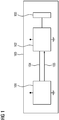
- Fig. 1 shows a compensator arrangement (100), such as a GSM compensator arrangement,) in a vehicle comprising a smart phone terminal (101), a (e.g. GSM) compensator (102) and an external antenna (103).
- the smart phone terminal (101) receives and transmits high frequency signals to and from, respectively, the compensator 102, which is connected to the external antenna 103.
- the RF connection between the smart phone terminal (101) and the compensator (102) is realized with a cable (104).
- the smart phone terminal (101) generates a control signal, e.g., a wake-up signal that is transmitted over a separate cable (105) to the compensator (102).
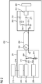
- a compensator arrangement (200) for a vehicle comprising a smart phone terminal (201) configured to connect to a mobile phone (215), a compensator (202) configured to improve a link quality and coverage for the mobile phone (215), and a cable (204) having a first wire (205) that carries a high frequency signal.
- the smart phone terminal (201) is configured to generate a control signal and to transmit the control signal on the first wire (205) to the compensator (202).
- the smart phone terminal (201) connects the mobile phone (215) to the cable (204) which may be a coaxial cable.
- the compensator (202) may be an amplifier or an equalizer.
- a DC switch (208) generates the control signal.
- the control signal passes the inductors (210, 209) and is fed into the wire 205 of the cable 204.
- the capacity 217 blocks the control signal so as not to interfere the RF signal in the matching circuit (207) and the antenna circuit (206) .
- the compensator (202) receives the control signal that is blocked by capacity (211) so as not to pass into the RF part (212) of the compensator (202) but to pass the inductor (216) and the driver (213).
- the control signal may be a wake-up signal and the compensator (202) is activated for nominal operation upon receiving the wake-up signal. Further components as e.g. the capacitor (214) and the resistor (219) may be present to match electrical specifications as voltage levels or impedances etc.
- the smart phone terminal (201) receives the RF signal from the mobile phone (215) using a plugged or an over-the-air connection (218), and feeds the signal over the smart phone terminal antenna circuit (206), the matching circuit (207) and the DC blocking capacitor (217) into the cable (204) .
- the compensator (202) receives the RF signal, passes it to the RF part (212) of the compensator (202), which amplifies and/or equalizes the signal and prepares it for transmission by the external antenna (203).
- Fig. 3 shows a vehicle (300) comprising a compensator arrangement (200) consisting of a compensator (202), a cable (204) and a smart phone terminal (201) according to embodiments of the invention.
- the compensator is connected to the external antenna (203) and the smart phone terminal (201) holds and is connected to the mobile phone (301).
Landscapes
- Engineering & Computer Science (AREA)
- Computer Networks & Wireless Communication (AREA)
- Signal Processing (AREA)
- Transceivers (AREA)
- Telephone Function (AREA)
- Transmitters (AREA)
Abstract
Description
- The present invention relates to mobile communication. More specifically, the present invention relates to a compensator arrangement for a vehicle, for example a GSM (Global System for Mobile Communications) compensator arrangement, comprising a smart phone terminal, a compensator, a smart phone terminal and a vehicle.
- A compensator arrangement or, more specifically, a mobile communication system compensator arrangement, such as a GSM compensator arrangement, generally represents the electrical infrastructure to connect a mobile phone to an external antenna of a vehicle. When communicating inside a vehicle using a mobile device, the chassis of the vehicle shields the electromagnetic waves, so that the link quality deteriorates. As a further effect, the mobile device increases its output power with possibly negative effects on the health of the user and on the lifetime of the battery of the mobile device. For these reasons, external antennas are used that are mounted, e.g. on the rooftop of a vehicle. The unimpeded received RF (radio frequency) signal is conducted by wire from the external antenna into the car, undergoing first some amplification or equalization in a compensator before it is further conducted by wire to a smart phone terminal in the cockpit that holds the mobile device. The terminal couples the received RF signal on the wire to the mobile using e.g. a passive antenna coupling method. The RF output signal of the mobile is conducted along the same way in opposite direction. The compensator may only need to be active when a mobile is residing in the terminal. Thus, usually the compensator provides a sleep mode where only a very few circuits are powered on. In the sleep mode the compensator listens whether a wake-up signal arrives. If a wake up signal occurs, the circuits that have been powered down are activated and the compensator is fully operable. The smart phone terminal generates the wake-up signal when detecting the presence of a mobile device in its cradle. The harness between the smart phone terminal and the GSM compensator consists of an RF cable, usually a coax cable, and a second cable for wake-up signal.
- It should be noted, that the mobile communication system may be a GSM mobile communication system, or a UMTS, LTE, 3G, 4G or 5G mobile communication system.
- There is a desire to reduce the costs and the effort arising by having two cables that have to be installed side by side and to simplify the harness.
- In one embodiment, a compensator arrangement for a vehicle is provided, comprising a smart phone terminal configured to connect to a mobile phone, a GSM compensator configured to improve a link quality and coverage for the mobile phone, and a cable having a first wire that carries a high frequency signal. The smart phone terminal is configured to generate a control signal and to transmit the control signal on the first wire to the compensator. The connection from the smart phone terminal to mobile phone is an RF link. This RF link may be established in a known way, e.g. over-the-air using a passive antenna or using a direct physical connection.
- According to a further embodiment, the smart phone terminal is a device for connecting a mobile phone to the cable and the compensator is a device for connecting the cable to an external antenna. The mobile transmits and receives RF signals. When transmitting, the RF from the mobile is received by the smart phone terminal as described above and is provided to the cable, which conducts the RF signal through its first wire to the compensator. The compensator conditions the RF signal and provides the conditioned RF signal to the external antenna. In receive direction the external antenna receives the RF signal from, e.g., a GSM base station. The RF signal then is conducted to the compensator that provides it to the cable where it is conducted through its first wire to the smart phone terminal. The smart phone terminal passes the RF signal by means of a direct physical connection or an over-the-air connection to the mobile phone.
- According to a further embodiment, the cable is a coax cable. The coax cable consists of an inner wire, usually a copper wire, and an outer shield, usually consisting of a metal and other components engineered to block signal interference. The inner wire, which is nominated "first wire" in the present specification, carries both the RF signal in both directions and the control signal, whereas the outer shield is connected to the electrical ground.
- According to a further embodiment, the compensator is an amplifier or an equalizer. The incoming and outgoing RF signals are attenuated on their path between mobile phone antenna and external antenna. The attenuation may also be frequency selective. The compensator compensates for these losses and conditions or matches the signal to optimize the signal for the mobile phone and the external antenna, respectively. By conditioning or matching, the RF signal may be improved in respect to, e.g., adapting the impedance or filtering the signal to suppress or eliminate unwanted signal components.
- According to a further embodiment, the control signal is coupled to the cable using an impedance. The cable transmits both signal types, i.e., the RF signals in both directions and the control signal from the smart phone terminal to the compensator at the same time on the same wire. Thus, the RF signals and the control signal have to be separated in the compensator and in the smart phone terminal in order to avoid mutual impacts on the corresponding circuits. This can be achieved using components with high impedance for high frequencies, as e.g. inductors to block the high frequency from the control signal circuits. Vice versa, capacitors are used to block the substantially DC (direct current) control signal.
- According to a further embodiment, the control signal is a wake-up signal and the compensator is activated upon receiving the wake-up signal. The wake-up signal may be generated, e.g., when a mobile device is detected at or near the smart phone terminal.
- According to an embodiment, a smart phone terminal for connecting a mobile phone to a high frequency transmitting cable is provided. The cable comprises a wire carrying the high frequency and the smart phone terminal is arranged to generate a control signal, and to couple the control signal to the wire. The smart phone terminal holds the mobile phone or a similar communication device that receives and transmits RF signals. The smart phone terminal comprises an interface to receive and transmit RF signals to and from the mobile phone. This interface may be a plugged connection or an over-the-air connection using components being capable to transfer RF energy between the mobile phone and the smart phone terminal. The wire of the cable carries these RF signals at the same time as the control signal. The smart phone terminal may be a multifunction smartphone terminal and may serve, e.g., as load station or data station for the mobile phone etc.
- According to a further embodiment, the control signal is a wake-up signal. The smart phone terminal detects the presence of a mobile phone and generates thereupon a wake-up signal intended to wake-up the compensator. There may be further conditions for generating the control signal. For example, the signal is generated only when the user presses a button, upon a voice command, or upon the detection of an outgoing call activity, etc.
- According to a further embodiment, the control signal of the smart phone terminal is coupled to the wire using an impedance. The use of impedances allows for separating high frequency signals from low frequency or DC signals or even for blocking them. In this way, the DC control signal can be blocked using e.g. capacitors, and the RF signals can blocked using, e.g., inductors.
- According to an embodiment, a compensator for connecting a high frequency transmitting cable to an external antenna is provided. The cable comprises a wire carrying the high frequency, and the GSM compensator is arranged to receive a control signal on this wire. The compensator represents the link between the external antenna and the cable that is further connected to the smart mobile terminal and the mobile phone. The compensator compensates for the losses that occur between the mobile phone and the external antenna in both directions, and adapts and optimizes the RF signals according to the electrical characteristics at the interface to the cable and the external antenna. The compensator comprises circuits to separate the RF signals and the control signals carried on the same wire and processes the signals in different circuits. The compensator is not limited to GSM signals.
- According to a further embodiment, the control signal is a wake-up signal and the compensator is activated upon receiving the wake-up signal. The compensator is configured to have an awake or nominal operation mode and a sleep mode in order to save energy. When in sleep mode, great parts of its circuits are powered off but it can still listen to a control signal. Upon receiving the control signal, the sleeping circuits are switched on and the compensator starts its operation.
- According to a further embodiment, the control signal is coupled to the wire using an impedance. Using impedances enables the compensator to separate the high frequency signals from the control signal, which is substantially a DC signal.
- According to an embodiment, a vehicle is provided wherein the vehicle comprises an arrangement according to one of the embodiments above.
- The accompanying figures illustrate embodiments of the invention.
- Fig. 1
- shows a compensator arrangement,
- Fig. 2
- shows a compensator arrangement according to an embodiment,
- Fig. 3
- shows a vehicle according to an embodiment.
-
Fig. 1 shows a compensator arrangement (100), such as a GSM compensator arrangement,) in a vehicle comprising a smart phone terminal (101), a (e.g. GSM) compensator (102) and an external antenna (103). The smart phone terminal (101) receives and transmits high frequency signals to and from, respectively, thecompensator 102, which is connected to theexternal antenna 103. The RF connection between the smart phone terminal (101) and the compensator (102) is realized with a cable (104). The smart phone terminal (101) generates a control signal, e.g., a wake-up signal that is transmitted over a separate cable (105) to the compensator (102). - Referring to
Fig. 2 , a compensator arrangement (200) for a vehicle is shown, comprising a smart phone terminal (201) configured to connect to a mobile phone (215), a compensator (202) configured to improve a link quality and coverage for the mobile phone (215), and a cable (204) having a first wire (205) that carries a high frequency signal. The smart phone terminal (201) is configured to generate a control signal and to transmit the control signal on the first wire (205) to the compensator (202). The smart phone terminal (201) connects the mobile phone (215) to the cable (204) which may be a coaxial cable. The compensator (202) may be an amplifier or an equalizer. - A DC switch (208) generates the control signal. The control signal passes the inductors (210, 209) and is fed into the
wire 205 of thecable 204. Thecapacity 217 blocks the control signal so as not to interfere the RF signal in the matching circuit (207) and the antenna circuit (206) . The compensator (202) receives the control signal that is blocked by capacity (211) so as not to pass into the RF part (212) of the compensator (202) but to pass the inductor (216) and the driver (213). The control signal may be a wake-up signal and the compensator (202) is activated for nominal operation upon receiving the wake-up signal. Further components as e.g. the capacitor (214) and the resistor (219) may be present to match electrical specifications as voltage levels or impedances etc. - The smart phone terminal (201) receives the RF signal from the mobile phone (215) using a plugged or an over-the-air connection (218), and feeds the signal over the smart phone terminal antenna circuit (206), the matching circuit (207) and the DC blocking capacitor (217) into the cable (204) . The compensator (202) receives the RF signal, passes it to the RF part (212) of the compensator (202), which amplifies and/or equalizes the signal and prepares it for transmission by the external antenna (203).
-
Fig. 3 shows a vehicle (300) comprising a compensator arrangement (200) consisting of a compensator (202), a cable (204) and a smart phone terminal (201) according to embodiments of the invention. The compensator is connected to the external antenna (203) and the smart phone terminal (201) holds and is connected to the mobile phone (301).
Claims (14)
- Compensator arrangement (200) for a vehicle, comprising a smart phone terminal (201) configured to connect to a mobile phone (215);
a compensator (202) configured to improve a link quality and coverage for the mobile phone (215); and
a cable (204) having a first wire (205) that carries a high frequency signal;
wherein the smart phone terminal (201) is configured to generate a control signal and to transmit the control signal on the first wire (205) to the GSM compensator (202). - Compensator arrangement (200) according to claim 1, wherein the smart phone terminal (201) is a device for connecting a mobile phone (215) to the cable (204); and
wherein the GSM compensator (202) is a device for connecting the cable (204) to an external antenna (203). - Compensator arrangement (200) according to one of the previous claims, wherein the cable (204) is a coaxial cable.
- Compensator arrangement (200) according to one of the previous claims, wherein the GSM compensator (202) is an amplifier or an equalizer.
- Compensator arrangement (200) according to one of the previous claims, wherein the control signal is a wake-up signal and the GSM compensator (202) is activated upon receiving the wake-up signal.
- Compensator arrangement (200) according to one of the previous claims, wherein the control signal is coupled to the cable (204) using an impedance (209, 210).
- Compensator arrangement (200) according to one of the previous claims, configured as a GSM compensator arrangement.
- Smart phone terminal (201) for connecting a mobile phone (215) to a high frequency transmitting cable (204);
wherein the cable (204) comprises a wire (205) carrying the high frequency;
wherein the smart phone terminal (201) is arranged to generate a control signal; and
wherein the smart phone terminal (201) is arranged to couple the control signal to the wire (205). - Smart phone terminal (201) according to claim 8 wherein the control signal is a wake-up signal.
- Smart phone terminal (201) according to claim 8 or 9 wherein the control signal is coupled to the wire (204) using an impedance (209, 210).
- Compensator (202) for connecting a high frequency transmitting cable (204) to an external antenna (203);
wherein the cable (204) comprises a wire (205) carrying the high frequency;
wherein the compensator (202) is arranged to receive a control signal on the wire (205). - Compensator (202) according to claim 11 wherein the control signal is a wake-up signal and wherein the GSM compensator (202) is activated upon receiving the wake-up signal.
- Compensator (202) according to claim 11 or 12 wherein the control signal is coupled to the wire (205) using an impedance (216) .
- Vehicle (300) comprising a Compensator arrangement (200) according to claims 1 to 8.
Priority Applications (1)
| Application Number | Priority Date | Filing Date | Title |
|---|---|---|---|
| EP18465506.6A EP3537613B1 (en) | 2018-03-07 | 2018-03-07 | Compensator arrangement |
Applications Claiming Priority (1)
| Application Number | Priority Date | Filing Date | Title |
|---|---|---|---|
| EP18465506.6A EP3537613B1 (en) | 2018-03-07 | 2018-03-07 | Compensator arrangement |
Publications (2)
| Publication Number | Publication Date |
|---|---|
| EP3537613A1 true EP3537613A1 (en) | 2019-09-11 |
| EP3537613B1 EP3537613B1 (en) | 2026-02-18 |
Family
ID=61873335
Family Applications (1)
| Application Number | Title | Priority Date | Filing Date |
|---|---|---|---|
| EP18465506.6A Active EP3537613B1 (en) | 2018-03-07 | 2018-03-07 | Compensator arrangement |
Country Status (1)
| Country | Link |
|---|---|
| EP (1) | EP3537613B1 (en) |
Citations (3)
| Publication number | Priority date | Publication date | Assignee | Title |
|---|---|---|---|---|
| EP0558210A1 (en) * | 1992-02-24 | 1993-09-01 | Nokia Mobile Phones Ltd. | Radio transceiver apparatus with booster |
| US20030100351A1 (en) * | 2001-11-27 | 2003-05-29 | Arrista Technologies, Inc. | Booster amplifier for cellular telephone cradles |
| US20090131131A1 (en) * | 2007-05-22 | 2009-05-21 | Wilson Electronics, Inc. | Mobile device cradle having an integrated antenna or amplifier |
Family Cites Families (1)
| Publication number | Priority date | Publication date | Assignee | Title |
|---|---|---|---|---|
| US11025290B2 (en) * | 2016-06-23 | 2021-06-01 | Lg Electronics Inc. | Communication signal compensator |
-
2018
- 2018-03-07 EP EP18465506.6A patent/EP3537613B1/en active Active
Patent Citations (3)
| Publication number | Priority date | Publication date | Assignee | Title |
|---|---|---|---|---|
| EP0558210A1 (en) * | 1992-02-24 | 1993-09-01 | Nokia Mobile Phones Ltd. | Radio transceiver apparatus with booster |
| US20030100351A1 (en) * | 2001-11-27 | 2003-05-29 | Arrista Technologies, Inc. | Booster amplifier for cellular telephone cradles |
| US20090131131A1 (en) * | 2007-05-22 | 2009-05-21 | Wilson Electronics, Inc. | Mobile device cradle having an integrated antenna or amplifier |
Also Published As
| Publication number | Publication date |
|---|---|
| EP3537613B1 (en) | 2026-02-18 |
Similar Documents
| Publication | Publication Date | Title |
|---|---|---|
| JP3048076B2 (en) | Mobile radio telephone | |
| CN102224653B (en) | Reduces interference between receiver and wireless power transmitter | |
| EP2847869B1 (en) | A transceiver with an integrated rx/tx configurable passive network | |
| EP2521221A1 (en) | Receiver and method for retrieving an information signal from a magnetic induction signal | |
| US20130149957A1 (en) | Adaptive repeater for improved communication system performance | |
| US9559729B2 (en) | Same-band combiner using dual-bandpass channel filters | |
| US10374653B2 (en) | V2X antenna systems | |
| CN102170305A (en) | Antenna performance control system and method | |
| JP2014532332A5 (en) | ||
| CN109547038B (en) | Inter-band uplink carrier aggregation radio frequency circuit, antenna device and electronic equipment | |
| HUP0200304A2 (en) | Integrated antenna coupler element | |
| CN102833884A (en) | Dual-mode mobile communication terminal | |
| US11223415B2 (en) | Repeater with low power mode for mobile operations | |
| MXPA05002234A (en) | Power amplifier bypass in a half-duplex ic. | |
| CN115483943A (en) | Vehicle-mounted antenna system, antenna compensator thereof and compensation method | |
| CN109150229B (en) | Mobile terminal and time division duplex system for controlling receiving sensitivity of TDD system | |
| US7133652B2 (en) | Circuit arrangement for compensation of the damping in an antenna feed cable for a mobile radio device | |
| JPH066154A (en) | Circuit configuration | |
| CN112737628A (en) | Radio frequency circuit and electronic device | |
| CN101562877A (en) | Remote method and equipment thereof for antenna of worldwide interoperability microwave access user terminal equipment | |
| US6892056B1 (en) | Subscriber station with duplex antenna amplifier | |
| US20190334570A1 (en) | Communication apparatus | |
| EP3537613B1 (en) | Compensator arrangement | |
| CN110365369B (en) | Power line carrier communication system supporting long-distance transmission | |
| CN117639834B (en) | Antenna circuit and OBU equipment |
Legal Events
| Date | Code | Title | Description |
|---|---|---|---|
| PUAI | Public reference made under article 153(3) epc to a published international application that has entered the european phase |
Free format text: ORIGINAL CODE: 0009012 |
|
| STAA | Information on the status of an ep patent application or granted ep patent |
Free format text: STATUS: THE APPLICATION HAS BEEN PUBLISHED |
|
| AK | Designated contracting states |
Kind code of ref document: A1 Designated state(s): AL AT BE BG CH CY CZ DE DK EE ES FI FR GB GR HR HU IE IS IT LI LT LU LV MC MK MT NL NO PL PT RO RS SE SI SK SM TR |
|
| AX | Request for extension of the european patent |
Extension state: BA ME |
|
| STAA | Information on the status of an ep patent application or granted ep patent |
Free format text: STATUS: REQUEST FOR EXAMINATION WAS MADE |
|
| 17P | Request for examination filed |
Effective date: 20200311 |
|
| RBV | Designated contracting states (corrected) |
Designated state(s): AL AT BE BG CH CY CZ DE DK EE ES FI FR GB GR HR HU IE IS IT LI LT LU LV MC MK MT NL NO PL PT RO RS SE SI SK SM TR |
|
| STAA | Information on the status of an ep patent application or granted ep patent |
Free format text: STATUS: EXAMINATION IS IN PROGRESS |
|
| 17Q | First examination report despatched |
Effective date: 20200915 |
|
| RAP1 | Party data changed (applicant data changed or rights of an application transferred) |
Owner name: CONTINENTAL AUTOMOTIVE TECHNOLOGIES GMBH |
|
| RAP3 | Party data changed (applicant data changed or rights of an application transferred) |
Owner name: CONTINENTAL AUTOMOTIVE TECHNOLOGIES GMBH |
|
| GRAP | Despatch of communication of intention to grant a patent |
Free format text: ORIGINAL CODE: EPIDOSNIGR1 |
|
| STAA | Information on the status of an ep patent application or granted ep patent |
Free format text: STATUS: GRANT OF PATENT IS INTENDED |
|
| INTG | Intention to grant announced |
Effective date: 20251006 |
|
| RAP3 | Party data changed (applicant data changed or rights of an application transferred) |
Owner name: AUMOVIO GERMANY GMBH |
|
| GRAS | Grant fee paid |
Free format text: ORIGINAL CODE: EPIDOSNIGR3 |
|
| GRAA | (expected) grant |
Free format text: ORIGINAL CODE: 0009210 |
|
| STAA | Information on the status of an ep patent application or granted ep patent |
Free format text: STATUS: THE PATENT HAS BEEN GRANTED |
|
| AK | Designated contracting states |
Kind code of ref document: B1 Designated state(s): AL AT BE BG CH CY CZ DE DK EE ES FI FR GB GR HR HU IE IS IT LI LT LU LV MC MK MT NL NO PL PT RO RS SE SI SK SM TR |
|
| REG | Reference to a national code |
Ref country code: CH Ref legal event code: F10 Free format text: ST27 STATUS EVENT CODE: U-0-0-F10-F00 (AS PROVIDED BY THE NATIONAL OFFICE) Effective date: 20260218 Ref country code: GB Ref legal event code: FG4D |
|
| REG | Reference to a national code |
Ref country code: DE Ref legal event code: R096 Ref document number: 602018089174 Country of ref document: DE |
|
| REG | Reference to a national code |
Ref country code: IE Ref legal event code: FG4D |
|
| REG | Reference to a national code |
Ref country code: NL Ref legal event code: MP Effective date: 20260218 |
|
| PG25 | Lapsed in a contracting state [announced via postgrant information from national office to epo] |
Ref country code: RS Free format text: LAPSE BECAUSE OF FAILURE TO SUBMIT A TRANSLATION OF THE DESCRIPTION OR TO PAY THE FEE WITHIN THE PRESCRIBED TIME-LIMIT Effective date: 20260518 |
|
| PG25 | Lapsed in a contracting state [announced via postgrant information from national office to epo] |
Ref country code: ES Free format text: LAPSE BECAUSE OF FAILURE TO SUBMIT A TRANSLATION OF THE DESCRIPTION OR TO PAY THE FEE WITHIN THE PRESCRIBED TIME-LIMIT Effective date: 20260218 |
|
| PG25 | Lapsed in a contracting state [announced via postgrant information from national office to epo] |
Ref country code: PL Free format text: LAPSE BECAUSE OF FAILURE TO SUBMIT A TRANSLATION OF THE DESCRIPTION OR TO PAY THE FEE WITHIN THE PRESCRIBED TIME-LIMIT Effective date: 20260218 |
|
| PG25 | Lapsed in a contracting state [announced via postgrant information from national office to epo] |
Ref country code: GR Free format text: LAPSE BECAUSE OF FAILURE TO SUBMIT A TRANSLATION OF THE DESCRIPTION OR TO PAY THE FEE WITHIN THE PRESCRIBED TIME-LIMIT Effective date: 20260519 |
|
| REG | Reference to a national code |
Ref country code: LT Ref legal event code: MG9D |
|
| PG25 | Lapsed in a contracting state [announced via postgrant information from national office to epo] |
Ref country code: LT Free format text: LAPSE BECAUSE OF FAILURE TO SUBMIT A TRANSLATION OF THE DESCRIPTION OR TO PAY THE FEE WITHIN THE PRESCRIBED TIME-LIMIT Effective date: 20260218 |
|
| PGFP | Annual fee paid to national office [announced via postgrant information from national office to epo] |
Ref country code: DE Payment date: 20260331 Year of fee payment: 9 |
|
| PG25 | Lapsed in a contracting state [announced via postgrant information from national office to epo] |
Ref country code: NO Free format text: LAPSE BECAUSE OF FAILURE TO SUBMIT A TRANSLATION OF THE DESCRIPTION OR TO PAY THE FEE WITHIN THE PRESCRIBED TIME-LIMIT Effective date: 20260518 |
|
| PG25 | Lapsed in a contracting state [announced via postgrant information from national office to epo] |
Ref country code: FI Free format text: LAPSE BECAUSE OF FAILURE TO SUBMIT A TRANSLATION OF THE DESCRIPTION OR TO PAY THE FEE WITHIN THE PRESCRIBED TIME-LIMIT Effective date: 20260218 Ref country code: AT Free format text: LAPSE BECAUSE OF FAILURE TO SUBMIT A TRANSLATION OF THE DESCRIPTION OR TO PAY THE FEE WITHIN THE PRESCRIBED TIME-LIMIT Effective date: 20260218 Ref country code: SE Free format text: LAPSE BECAUSE OF FAILURE TO SUBMIT A TRANSLATION OF THE DESCRIPTION OR TO PAY THE FEE WITHIN THE PRESCRIBED TIME-LIMIT Effective date: 20260218 |
|
| REG | Reference to a national code |
Ref country code: AT Ref legal event code: MK05 Ref document number: 1889332 Country of ref document: AT Kind code of ref document: T Effective date: 20260218 |
|
| PG25 | Lapsed in a contracting state [announced via postgrant information from national office to epo] |
Ref country code: HR Free format text: LAPSE BECAUSE OF FAILURE TO SUBMIT A TRANSLATION OF THE DESCRIPTION OR TO PAY THE FEE WITHIN THE PRESCRIBED TIME-LIMIT Effective date: 20260218 |
|
| PG25 | Lapsed in a contracting state [announced via postgrant information from national office to epo] |
Ref country code: PT Free format text: LAPSE BECAUSE OF FAILURE TO SUBMIT A TRANSLATION OF THE DESCRIPTION OR TO PAY THE FEE WITHIN THE PRESCRIBED TIME-LIMIT Effective date: 20260618 Ref country code: IS Free format text: LAPSE BECAUSE OF FAILURE TO SUBMIT A TRANSLATION OF THE DESCRIPTION OR TO PAY THE FEE WITHIN THE PRESCRIBED TIME-LIMIT Effective date: 20260618 |
|
| PG25 | Lapsed in a contracting state [announced via postgrant information from national office to epo] |
Ref country code: NL Free format text: LAPSE BECAUSE OF FAILURE TO SUBMIT A TRANSLATION OF THE DESCRIPTION OR TO PAY THE FEE WITHIN THE PRESCRIBED TIME-LIMIT Effective date: 20260218 |
|
| PG25 | Lapsed in a contracting state [announced via postgrant information from national office to epo] |
Ref country code: LV Free format text: LAPSE BECAUSE OF FAILURE TO SUBMIT A TRANSLATION OF THE DESCRIPTION OR TO PAY THE FEE WITHIN THE PRESCRIBED TIME-LIMIT Effective date: 20260218 |
|
| PG25 | Lapsed in a contracting state [announced via postgrant information from national office to epo] |
Ref country code: BG Free format text: LAPSE BECAUSE OF FAILURE TO SUBMIT A TRANSLATION OF THE DESCRIPTION OR TO PAY THE FEE WITHIN THE PRESCRIBED TIME-LIMIT Effective date: 20260218 |