US11223415B2 - Repeater with low power mode for mobile operations - Google Patents
Repeater with low power mode for mobile operations Download PDFInfo
- Publication number
- US11223415B2 US11223415B2 US16/882,265 US202016882265A US11223415B2 US 11223415 B2 US11223415 B2 US 11223415B2 US 202016882265 A US202016882265 A US 202016882265A US 11223415 B2 US11223415 B2 US 11223415B2
- Authority
- US
- United States
- Prior art keywords
- repeater
- signal
- mobile repeater
- mobile
- voltage
- Prior art date
- Legal status (The legal status is an assumption and is not a legal conclusion. Google has not performed a legal analysis and makes no representation as to the accuracy of the status listed.)
- Active
Links
Images


Classifications
-
- H—ELECTRICITY
- H04—ELECTRIC COMMUNICATION TECHNIQUE
- H04W—WIRELESS COMMUNICATION NETWORKS
- H04W52/00—Power management, e.g. TPC [Transmission Power Control], power saving or power classes
- H04W52/02—Power saving arrangements
- H04W52/0209—Power saving arrangements in terminal devices
- H04W52/0261—Power saving arrangements in terminal devices managing power supply demand, e.g. depending on battery level
- H04W52/0274—Power saving arrangements in terminal devices managing power supply demand, e.g. depending on battery level by switching on or off the equipment or parts thereof
- H04W52/0277—Power saving arrangements in terminal devices managing power supply demand, e.g. depending on battery level by switching on or off the equipment or parts thereof according to available power supply, e.g. switching off when a low battery condition is detected
-
- H—ELECTRICITY
- H02—GENERATION; CONVERSION OR DISTRIBUTION OF ELECTRIC POWER
- H02J—CIRCUIT ARRANGEMENTS OR SYSTEMS FOR SUPPLYING OR DISTRIBUTING ELECTRIC POWER; SYSTEMS FOR STORING ELECTRIC ENERGY
- H02J9/00—Circuit arrangements for emergency or stand-by power supply, e.g. for emergency lighting
- H02J9/005—Circuit arrangements for emergency or stand-by power supply, e.g. for emergency lighting using a power saving mode
-
- H—ELECTRICITY
- H04—ELECTRIC COMMUNICATION TECHNIQUE
- H04B—TRANSMISSION
- H04B1/00—Details of transmission systems, not covered by a single one of groups H04B3/00 - H04B13/00; Details of transmission systems not characterised by the medium used for transmission
- H04B1/005—Details of transmission systems, not covered by a single one of groups H04B3/00 - H04B13/00; Details of transmission systems not characterised by the medium used for transmission adapting radio receivers, transmitters andtransceivers for operation on two or more bands, i.e. frequency ranges
- H04B1/0053—Details of transmission systems, not covered by a single one of groups H04B3/00 - H04B13/00; Details of transmission systems not characterised by the medium used for transmission adapting radio receivers, transmitters andtransceivers for operation on two or more bands, i.e. frequency ranges with common antenna for more than one band
- H04B1/0057—Details of transmission systems, not covered by a single one of groups H04B3/00 - H04B13/00; Details of transmission systems not characterised by the medium used for transmission adapting radio receivers, transmitters andtransceivers for operation on two or more bands, i.e. frequency ranges with common antenna for more than one band using diplexing or multiplexing filters for selecting the desired band
-
- H—ELECTRICITY
- H04—ELECTRIC COMMUNICATION TECHNIQUE
- H04B—TRANSMISSION
- H04B1/00—Details of transmission systems, not covered by a single one of groups H04B3/00 - H04B13/00; Details of transmission systems not characterised by the medium used for transmission
- H04B1/06—Receivers
- H04B1/16—Circuits
- H04B1/1607—Supply circuits
-
- H—ELECTRICITY
- H04—ELECTRIC COMMUNICATION TECHNIQUE
- H04B—TRANSMISSION
- H04B1/00—Details of transmission systems, not covered by a single one of groups H04B3/00 - H04B13/00; Details of transmission systems not characterised by the medium used for transmission
- H04B1/38—Transceivers, i.e. devices in which transmitter and receiver form a structural unit and in which at least one part is used for functions of transmitting and receiving
- H04B1/3827—Portable transceivers
- H04B1/3877—Arrangements for enabling portable transceivers to be used in a fixed position, e.g. cradles or boosters
-
- H—ELECTRICITY
- H04—ELECTRIC COMMUNICATION TECHNIQUE
- H04B—TRANSMISSION
- H04B1/00—Details of transmission systems, not covered by a single one of groups H04B3/00 - H04B13/00; Details of transmission systems not characterised by the medium used for transmission
- H04B1/38—Transceivers, i.e. devices in which transmitter and receiver form a structural unit and in which at least one part is used for functions of transmitting and receiving
- H04B1/3827—Portable transceivers
- H04B1/3888—Arrangements for carrying or protecting transceivers
-
- H—ELECTRICITY
- H04—ELECTRIC COMMUNICATION TECHNIQUE
- H04B—TRANSMISSION
- H04B7/00—Radio transmission systems, i.e. using radiation field
- H04B7/14—Relay systems
- H04B7/15—Active relay systems
- H04B7/155—Ground-based stations
- H04B7/15528—Control of operation parameters of a relay station to exploit the physical medium
- H04B7/15535—Control of relay amplifier gain
-
- H—ELECTRICITY
- H04—ELECTRIC COMMUNICATION TECHNIQUE
- H04B—TRANSMISSION
- H04B7/00—Radio transmission systems, i.e. using radiation field
- H04B7/14—Relay systems
- H04B7/15—Active relay systems
- H04B7/155—Ground-based stations
- H04B7/15557—Selecting relay station operation mode, e.g. between amplify and forward mode, decode and forward mode or FDD - and TDD mode
-
- H—ELECTRICITY
- H04—ELECTRIC COMMUNICATION TECHNIQUE
- H04B—TRANSMISSION
- H04B7/00—Radio transmission systems, i.e. using radiation field
- H04B7/14—Relay systems
- H04B7/15—Active relay systems
- H04B7/185—Space-based or airborne stations; Stations for satellite systems
- H04B7/1853—Satellite systems for providing telephony service to a mobile station, i.e. mobile satellite service
- H04B7/18539—Arrangements for managing radio, resources, i.e. for establishing or releasing a connection
- H04B7/18543—Arrangements for managing radio, resources, i.e. for establishing or releasing a connection for adaptation of transmission parameters, e.g. power control
-
- H—ELECTRICITY
- H04—ELECTRIC COMMUNICATION TECHNIQUE
- H04W—WIRELESS COMMUNICATION NETWORKS
- H04W52/00—Power management, e.g. TPC [Transmission Power Control], power saving or power classes
- H04W52/02—Power saving arrangements
- H04W52/0203—Power saving arrangements in the radio access network or backbone network of wireless communication networks
- H04W52/0206—Power saving arrangements in the radio access network or backbone network of wireless communication networks in access points, e.g. base stations
-
- H—ELECTRICITY
- H02—GENERATION; CONVERSION OR DISTRIBUTION OF ELECTRIC POWER
- H02J—CIRCUIT ARRANGEMENTS OR SYSTEMS FOR SUPPLYING OR DISTRIBUTING ELECTRIC POWER; SYSTEMS FOR STORING ELECTRIC ENERGY
- H02J7/00—Circuit arrangements for charging or depolarising batteries or for supplying loads from batteries
- H02J7/00032—Circuit arrangements for charging or depolarising batteries or for supplying loads from batteries characterised by data exchange
- H02J7/00034—Charger exchanging data with an electronic device, i.e. telephone, whose internal battery is under charge
-
- H—ELECTRICITY
- H02—GENERATION; CONVERSION OR DISTRIBUTION OF ELECTRIC POWER
- H02J—CIRCUIT ARRANGEMENTS OR SYSTEMS FOR SUPPLYING OR DISTRIBUTING ELECTRIC POWER; SYSTEMS FOR STORING ELECTRIC ENERGY
- H02J7/00—Circuit arrangements for charging or depolarising batteries or for supplying loads from batteries
- H02J7/0029—Circuit arrangements for charging or depolarising batteries or for supplying loads from batteries with safety or protection devices or circuits
- H02J7/0031—Circuit arrangements for charging or depolarising batteries or for supplying loads from batteries with safety or protection devices or circuits using battery or load disconnect circuits
- H02J7/0032—Circuit arrangements for charging or depolarising batteries or for supplying loads from batteries with safety or protection devices or circuits using battery or load disconnect circuits disconnection of loads if battery is not under charge, e.g. in vehicle if engine is not running
-
- Y—GENERAL TAGGING OF NEW TECHNOLOGICAL DEVELOPMENTS; GENERAL TAGGING OF CROSS-SECTIONAL TECHNOLOGIES SPANNING OVER SEVERAL SECTIONS OF THE IPC; TECHNICAL SUBJECTS COVERED BY FORMER USPC CROSS-REFERENCE ART COLLECTIONS [XRACs] AND DIGESTS
- Y02—TECHNOLOGIES OR APPLICATIONS FOR MITIGATION OR ADAPTATION AGAINST CLIMATE CHANGE
- Y02B—CLIMATE CHANGE MITIGATION TECHNOLOGIES RELATED TO BUILDINGS, e.g. HOUSING, HOUSE APPLIANCES OR RELATED END-USER APPLICATIONS
- Y02B70/00—Technologies for an efficient end-user side electric power management and consumption
- Y02B70/30—Systems integrating technologies related to power network operation and communication or information technologies for improving the carbon footprint of the management of residential or tertiary loads, i.e. smart grids as climate change mitigation technology in the buildings sector, including also the last stages of power distribution and the control, monitoring or operating management systems at local level
-
- Y—GENERAL TAGGING OF NEW TECHNOLOGICAL DEVELOPMENTS; GENERAL TAGGING OF CROSS-SECTIONAL TECHNOLOGIES SPANNING OVER SEVERAL SECTIONS OF THE IPC; TECHNICAL SUBJECTS COVERED BY FORMER USPC CROSS-REFERENCE ART COLLECTIONS [XRACs] AND DIGESTS
- Y02—TECHNOLOGIES OR APPLICATIONS FOR MITIGATION OR ADAPTATION AGAINST CLIMATE CHANGE
- Y02D—CLIMATE CHANGE MITIGATION TECHNOLOGIES IN INFORMATION AND COMMUNICATION TECHNOLOGIES [ICT], I.E. INFORMATION AND COMMUNICATION TECHNOLOGIES AIMING AT THE REDUCTION OF THEIR OWN ENERGY USE
- Y02D30/00—Reducing energy consumption in communication networks
- Y02D30/70—Reducing energy consumption in communication networks in wireless communication networks
-
- Y—GENERAL TAGGING OF NEW TECHNOLOGICAL DEVELOPMENTS; GENERAL TAGGING OF CROSS-SECTIONAL TECHNOLOGIES SPANNING OVER SEVERAL SECTIONS OF THE IPC; TECHNICAL SUBJECTS COVERED BY FORMER USPC CROSS-REFERENCE ART COLLECTIONS [XRACs] AND DIGESTS
- Y04—INFORMATION OR COMMUNICATION TECHNOLOGIES HAVING AN IMPACT ON OTHER TECHNOLOGY AREAS
- Y04S—SYSTEMS INTEGRATING TECHNOLOGIES RELATED TO POWER NETWORK OPERATION, COMMUNICATION OR INFORMATION TECHNOLOGIES FOR IMPROVING THE ELECTRICAL POWER GENERATION, TRANSMISSION, DISTRIBUTION, MANAGEMENT OR USAGE, i.e. SMART GRIDS
- Y04S20/00—Management or operation of end-user stationary applications or the last stages of power distribution; Controlling, monitoring or operating thereof
- Y04S20/20—End-user application control systems
Definitions
- Signal boosters can be used to increase the quality of wireless communication between a wireless device and a wireless communication access point, such as a cell tower. Signal boosters can improve the quality of the wireless communication by amplifying, filtering, and/or applying other processing techniques to uplink (UL) and downlink (DL) signals communicated between the wireless device and the wireless communication access point.
- UL uplink
- DL downlink
- the signal booster can receive, via an antenna, downlink signals from the wireless communication access point.
- the signal booster can amplify the downlink signal and then provide an amplified downlink signal to the wireless device.
- the signal booster can act as a relay between the wireless device and the wireless communication access point.
- the wireless device can receive a stronger signal from the wireless communication access point.
- uplink signals from the wireless device e.g., telephone calls and other data
- the signal booster can amplify the uplink signals before communicating, via the antenna, the uplink signals to the wireless communication access point.
- FIG. 1 illustrates a signal booster in communication with a wireless device and a base station in accordance with an example
- FIG. 2 illustrates a bi-directional amplifier in accordance with an example
- FIG. 3 illustrates a multi-band bi-directional amplifier in accordance with an example
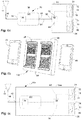
- FIG. 4 is a perspective view of a cradle of a repeater system, with a wireless user device, namely a cellular phone, removed from the cradle, in accordance with an example;
- FIG. 5 is a perspective view of the cradle of a repeater system, with the wireless user device or the cellular phone carried by the cradle, in accordance with an example;
- FIG. 6 a is a schematic view of a repeater system in accordance with an example
- FIG. 6 b is a perspective view of cradles of the repeater system of FIG. 6 a , with first and second wireless user devices removed from the cradles in accordance with an example;
- FIG. 6 c is a schematic view of a repeater system in accordance with another example.
- FIG. 6 d is a perspective view of a cradle of the repeater system of FIG. 6 a with first and second wireless user devices not located on the cradle in accordance with an example;
- FIG. 7 a is a schematic view of another repeater system in accordance with another example.
- FIG. 7 b is a schematic view of another repeater system in accordance with another example.
- FIG. 8 illustrates functionality of a mobile repeater operable to operate in a low power mode, in accordance with an example
- FIG. 9 illustrates functionality of a mobile repeater coupled to a mobile device cradle operable to operate in a low power mode, the mobile repeater, in accordance with an example
- FIG. 10 illustrates functionality of a power adapter for a mobile repeater for reducing battery power consumption, in accordance with an example
- FIG. 11 illustrates a diagram of a wireless device (e.g., UE) in accordance with an example.
- a wireless device e.g., UE
- cellular and “cellular network” refer to a wireless telephone network that connects radio transmissions between a mobile phone and a system of multiple cell sites, each including an antenna and a base station, to a mobile telephone switching office, and ultimately to the public wire line telephone system. Cellular calls are transferred from base station to base station as a user travels from cell to cell.
- cellular network refers to a wireless telephone network that connects radio transmissions between a mobile phone and a system of multiple cell sites, each including an antenna and a base station, to a mobile telephone switching office, and ultimately to the public wire line telephone system. Cellular calls are transferred from base station to base station as a user travels from cell to cell.
- embodiments of the invention can be applied to other wireless networks including those operating on various frequencies throughout the electromagnetic spectrum.
- the phrase “cell phone” or “cellular phone” refer to a wireless device that sends and receives messages using radio frequency signals in the appropriate band.
- the phrase “cellular signal” refers to signals being transmitted in spectrum allocated for cellular communications, such as the third generation partnership project (3GPP) long term evolution (LTE) bands 1-85.
- 3GPP third generation partnership project
- LTE long term evolution
- embodiments of the invention are not limited to operation in these frequency spectrums, but can be applied in other portions of the frequency spectrum as well.
- other wireless devices such as personal digital assistants, laptop computers, and the like can benefit from or be incorporated into embodiments of the invention.
- Cell site and base station are used herein interchangeably.
- Cell site and base station are defined as the location where the wireless network antenna and communications equipment is placed.
- a cell site or base station typically includes a transmitter/receiver, antenna tower, transmission radios and radio controllers for maintaining communications with mobile handsets within a given range.
- a cell phone or cellular device may represent one or more such devices.
- base station or cell site can refer to one or more base stations.
- Cell phone may also represent other devices that communicate through the amplifier.
- Embodiments of the amplifier may amplify signals for one or more cell phones in communication with one or more base stations.
- uplink signal refers to the transmission path of a signal being transmitted from a handset to a base station.
- downlink signal refers to the transmission path of a signal being transmitted from the base station to the handset.
- uplink signal and downlink are not limited to any particular type of data that may be transmitted between a handset and a base station, but instead are simply used to specify the direction in which a signal is being transmitted.
- Cellular repeaters are often used in vehicles to enable wireless user devices to communicate with base stations while traveling in a vehicle through remote areas or other areas with low power cellular signals.
- the cellular repeaters are typically powered using a vehicle power supply, such as a cigarette lighter adapter (CLA) connected to a car's 12 volt battery.
- a vehicle power supply such as a cigarette lighter adapter (CLA) connected to a car's 12 volt battery.
- CLA cigarette lighter adapter
- Vehicles are evolving to include more and more electronics within the vehicle. In addition, people are bringing more external electronics into vehicles and powering them. For example, cell phones, tablets, and laptops are often charged in a vehicle. To accommodate the need for additional charging, vehicle manufacturers are providing more means for connecting to a vehicle's power supply. In some vehicles, the power supply connections are designed to stay on, even when the vehicle is turned off. This can be beneficial to powering digital devices. Some types of digital devices can have a fairly low current draw. However, other types of devices, such as some
- the power level of the vehicle can be identified to determine if the vehicle is active (i.e. the vehicle is charging or providing current from the vehicle alternator) or inactive (i.e. the vehicle is not charging or providing current).
- a cellular repeater such as a mobile repeater, can be configured to be placed in a low power mode for mobile operations when a vehicle is inactive.
- the mobile repeater can be a dual band repeater, a multiple band repeater, or a single band repeater.
- FIG. 1 illustrates an exemplary signal booster 120 in communication with a wireless device 110 and a base station 130 .
- the signal booster 120 (also referred to as a cellular signal amplifier, a cellular repeater, or a repeater) can improve the quality of wireless communication by amplifying, filtering, and/or applying other processing techniques via a signal amplifier 122 to uplink signals communicated from the wireless device 110 to the base station 130 and/or downlink signals communicated from the base station 130 to the wireless device 110 .
- the signal booster 120 can amplify or boost uplink signals and/or downlink signals bi-directionally.
- the signal booster 120 can be at a fixed location, such as in a home or office.
- the signal booster 120 can be configured as a mobile booster that is attached to a mobile object, such as a vehicle, marine vehicle, or a wireless device 110 .
- the signal booster 120 can include a server antenna 124 (e.g., an inside antenna or device antenna or a coupling antenna) and a donor antenna 126 (e.g., an outside antenna or node antenna).
- the server antenna 124 and/or the donor antenna can be integrated.
- the donor antenna 126 can receive the downlink signal from the base station 130 .
- the downlink signal can be provided to the signal amplifier 122 via a second coaxial cable 127 or other type of radio frequency connection operable to communicate radio frequency signals, such as a fiber optic cable or twisted shielded pair cable.
- the signal amplifier 122 can include one or more cellular signal amplifiers for amplification and filtering.
- the downlink signal that has been amplified and filtered can be provided to the server antenna 124 via a first coaxial cable 125 or other type of radio frequency connection operable to communicate radio frequency signals.
- the server antenna 124 can wirelessly communicate the downlink signal that has been amplified and filtered to the wireless device 110 .
- the server antenna 124 can receive an uplink signal from the wireless device 110 .
- the uplink signal can be provided to the signal amplifier 122 via the first coaxial cable 125 or other type of radio frequency connection operable to communicate radio frequency signals.
- the signal amplifier 122 can include one or more cellular signal amplifiers for amplification and filtering.
- the uplink signal that has been amplified and filtered can be provided to the donor antenna 126 via the second coaxial cable 127 or other type of radio frequency connection operable to communicate radio frequency signals.
- the donor antenna 126 can communicate the uplink signal that has been amplified and filtered to a node, such as base station 130 .
- the signal booster 120 can send uplink signals to a node and/or receive downlink signals from the node.
- FIG. 1 shows the node as a base station 130 , this is not intended to be limiting.
- the node can comprise a wireless wide area network (WWAN) access point (AP), a base station (BS), an evolved Node B (eNB), a baseband unit (BBU), a remote radio head (RRH), a remote radio equipment (RRE), a relay station (RS), a radio equipment (RE), a remote radio unit (RRU), a central processing module (CPM), or another type of WWAN access point.
- WWAN wireless wide area network
- AP wireless wide area network
- BS base station
- eNB evolved Node B
- BBU baseband unit
- RRH remote radio head
- RRE remote radio equipment
- RS relay station
- RE radio equipment
- RRU remote radio unit
- CCM central processing module
- the repeater 30 or signal booster can be a Federal Communications Commission (FCC)-compatible consumer signal booster.
- FCC Federal Communications Commission
- the repeater 30 or signal booster can be compatible with FCC Part 20 or 47 Code of Federal Regulations (C.F.R.) Part 20.21 (Mar. 21, 2013).
- the repeater 30 or signal booster can operate on the frequencies used for the provision of subscriber-based services under parts 22 (Cellular), 24 (Broadband PCS), 27 (AWS-1, 700 MHz Lower A-E Blocks, and 700 MHz Upper C Block), and 90 (Specialized Mobile Radio) of 47 C.F.R.
- the repeater 30 or signal booster can be configured to automatically self-monitor its operation to ensure compliance with applicable noise and gain limits.
- the repeater 30 or signal booster can either self-correct or shut down automatically if the signal booster's operations violate the regulations defined in 47 CFR Part 20.21.
- the repeater 30 or signal booster can improve the wireless connection between the wireless user devices 78 and 80 and the base station (e.g., cell tower) or another type of wireless wide area network (WWAN) access point (AP).
- the repeater 30 can boost signals from the Third Generation Partnership Project (3GPP) Technical Specification (TS) 36.101 (Release 16 Jan. 2019) bands or LTE frequency bands.
- 3GPP Third Generation Partnership Project
- TS Technical Specification
- the repeater 30 can boost signals from the LTE frequency bands: 2, 4, 5, 12, 13, 17, 25, and 26.
- the repeater 30 can boost selected frequency bands based on the country or region in which the repeater is used, including any of bands 1-85 or other bands, as disclosed in 3GPP TS 36.104 V16.0.0 (January 2019).
- the repeater 30 can boost signals from the 3GPP Technical Specification (TS) 38.104 (Release 15 Jan. 2019) bands or 5G frequency bands.
- the repeater 220 can boost selected frequency bands based on the country or region in which the repeater is used, including any of bands n1-n86, n257-n261, or other bands, as disclosed in 3GPP TS 38.104 V15.4.0 (January 2019).
- the number of LTE frequency bands and the level of signal improvement can vary based on a particular wireless user device, cellular node, or location. Additional domestic and international frequencies can also be included to offer increased functionality. Selected models of the repeater 30 or signal booster can be configured to operate with selected frequency bands based on the location of use. In another example, the repeater 30 or signal booster can automatically sense from the wireless user devices 78 and 80 or base station (or GPS, etc.) which frequencies are used, which can be a benefit for international travelers.
- FIG. 2 shows a more detailed drawing of a repeater.
- the repeater can be configured to be coupled to a server antenna 202 and a donor antenna 204 .
- the server antenna can be coupled to a diplexer or duplexer 212 .
- the donor antenna can be coupled to a diplexer or duplexer 214 .
- a first direction amplification and filtering path 230 and a second direction amplification and filtering path 240 can be coupled between the diplexer or duplexers 212 , 214 .
- the first direction amplification and filtering path 230 can comprise a low noise amplifier (LNA) 222 , a variable attenuator 224 , a filter 226 , such as a bandpass filter, and a power amplifier (PA) 228 .
- LNA low noise amplifier
- PA power amplifier
- the LNA 222 can amplify a low power signal with minimal degradation of the signal to noise ratio of the low power signal.
- the PA 228 can adjust and amplify the power level of the low power signal by a desired amount.
- the PA can be comprised of an amplifier chain that can include one or more amplifiers configured to apply a gain to signals received by the amplifier chain.
- the second direction amplification and filtering path 240 can comprise an LNA 232 , a variable attenuator 234 , a filter 236 , and a PA 238 that can be comprised of an amplifier chain.
- the first direction amplification and filtering path 230 can be a downlink amplification path or an uplink amplification path.
- the second direction amplification and filtering path 240 can be a downlink amplification path or an uplink amplification path.
- the repeater 200 can also comprise a controller 210 .
- the controller 210 can include one or more processors and memory.
- the controller 200 can be implemented by any suitable mechanism, such as a program, software, function, library, software as a service, analog or digital circuitry, or any combination thereof.
- the controller 200 can also include a processor coupled to memory.
- the processor can include, for example, a microprocessor, microcontroller, digital signal processor (DSP), application specific integrated circuit (ASIC), a Field Programmable Gate Array (FPGA), or any other digital or analog circuitry configured to interpret and/or to execute program instructions and/or to process data.
- the processor can interpret and/or execute program instructions and/or process data stored in the memory.
- the instructions can include instructions for adjusting the gain of the amplifier chain. For example, the adjustments can be based on radio frequency (RF) signal inputs.
- RF radio frequency
- the memory can include any suitable computer readable media configured to retain program instructions and/or data for a period of time.
- computer readable media can include tangible computer readable storage media including random access memory (RAM), read only memory (ROM), electrically erasable programmable read only memory (EEPROM), a compact disk (CD) ROM or other optical disk storage, magnetic disk storage or other magnetic storage devices, flash memory devices (e.g., solid state memory devices) or any other storage medium which can be used to carry or store desired program code in the form of computer executable instructions or data structures and which can be accessed by a general purpose or special purpose computer. Combinations of the above can also be included within the scope of computer readable media.
- Computer executable instructions can include, for example, instructions and data that cause a general purpose computer, special purpose computer, or special purpose processing device to perform a certain function or group of functions.
- FIG. 3 provides an example illustration of a multiband repeater 300 .
- the multiband bi-directional wireless repeater 300 can be configured to amplify an uplink signal and a downlink signal in multiple bands using a separate signal path for each uplink frequency band and downlink frequency band. In one embodiment, adjacent bands can be included on a same signal path.
- the repeater can be configured to be coupled to a donor antenna 310 and a server antenna 330 .
- the donor antenna 310 can receive a downlink signal.
- the downlink signal can be received from a base station.
- the downlink signal can be provided to a first B1/B2 diplexer 312 , wherein B1 represents a first frequency band and B2 represents a second frequency band.
- B1 and B2 frequency bands are used generically in this example and do not represent a specific 3GPP frequency range.
- the first B1/B2 diplexer 312 can direct selected portions of a received signal to a B1 downlink signal path and a B2 downlink signal path. Therefore, a downlink signal that is associated with B1 can travel along the B1 downlink signal path to a first B1 duplexer 314 .
- a portion of the received signal that is within the B2 band can travel along the B2 downlink signal path to a first B2 duplexer 316 .
- the downlink signal can travel through a series of amplifiers (e.g. A10, A11, and A12) and downlink bandpass filters (BPF) to a second B1 duplexer 318 .
- the B2 downlink signal passing through the B2 duplexer 316 can travel through a series of amplifiers (e.g. A07, A08, and A09) and downlink band pass filters (BPF) to a second B2 duplexer 320 .
- the downlink signals (B1 or B2) have been amplified and filtered in accordance with the type of amplifiers and BPFs included in the multiband bi-directional wireless signal booster 300 .
- the second B1/B2 diplexer 322 can direct the B1/B2 amplified downlink signal to the server antenna 330 .
- the server antenna 330 can communicate the amplified downlink signal to a wireless device, such as a user equipment (UE).
- UE user equipment
- the server antenna 330 can receive an uplink (UL) signal from a wireless device.
- the uplink signal can include a Band 1 signal and a Band 2 signal.
- the uplink signal can be provided to the second B1/B2 diplexer 322 .
- the second B1/B2 diplexer 322 can direct the signals, based on their frequency, to a B1 uplink signal path and a B2 uplink signal path. Therefore, an uplink signal that is associated with B1 can travel along the B1 uplink signal path to a second B1 duplexer 318 , and an uplink signal that is associated with B2 can travel along the B2 uplink signal path to a second B2 duplexer 320 .
- the second B1 duplexer 318 can direct the B1 uplink signal to travel through a series of amplifiers (e.g. A01, A02, and A03) and uplink bandpass filters (BPF) to the first B1 duplexer 314 .
- the second B2 duplexer 320 can direct the B2 uplink signal to travel through an amplifier chain comprising a series of amplifiers (e.g. A04, A05, and A06) and downlink band pass filters (BPF) to the first B2 duplexer 316 .
- the uplink signals (B1 and B2) have been amplified and filtered in accordance with the type of amplifiers and BPFs included in the bi-directional wireless repeater 300 .
- the uplink signals from the first B1 duplexer 314 and the first B2 duplexer 316 , respectively, can be provided to the first B1/B2 diplexer 312 .
- the first B1/B2 diplexer 312 can direct the B1 and B2 amplified uplink signals to the donor antenna 310 .
- the donor antenna 310 can communicate the amplified uplink signals to a base station.
- a repeater designed for a mobile vehicle can be configured to be attached to a vehicle mount or cradle that is designed to carry one or more wireless user devices.
- FIG. 4 and FIG. 5 depict a perspective view of a cradle 24 configured to be coupled to a repeater.
- the cradle is illustrated with a wireless user device 78 , namely a cellular phone.
- the wireless user device 78 can be carried by the cradle 24 and removed from the cradle 24 .
- a radio frequency connection 68 can be used to couple the cradle 24 to the repeater system.
- the repeater system can boost or amplify one or more radio frequency (RF) communication signals between a donor antenna and one or more server antennas.
- the donor antenna can be an exterior donor antenna disposed outside of a vehicle or structure.
- the server antenna can be an RF signal coupler carried by and disposed in the cradle 24 .
- the repeater system can comprise a repeater, the mobile device cradle 24 with one or more server antennas configured as RF signal couplers, and the donor antenna.
- the repeater can comprise a bi-directional amplifier (BDA) to amplify the one or more RF communication signals in a first direction and a second direction.
- BDA bi-directional amplifier
- the repeater can improve the quality of wireless communication and the one or more RF communication signals by amplifying, filtering, and/or applying other processing techniques via the BDA.
- the mobile device cradle can be disposed in a desired location, such as inside a vehicle, RV, marine vehicle (i.e. boat) or the like.
- the repeater can include a donor port configured to be coupled to the donor antenna.
- the donor port can be a co-axial coupler or other type of RF cable 68 operable to couple to the donor antenna, or other type of radio frequency connection operable to communicate radio frequency signals.
- the repeater can also have a server port.
- the server port can be operatively coupled to the repeater.
- the server port can be coupled to the RF cable 68 that is coupled to the mobile device cradle 24 .
- the server port can be configured to provide an electrical connection between the repeater and the mobile device cradle 24 .
- the RF cable 68 or another cable, can be configured to be coupled to a power supply, such as the CLA, in order to receive power from a vehicle, to be supplied to the mobile device cradle 24 .
- the mobile device cradle 24 can have an interface 72 , respectively, capable of selectively carrying a wireless user device 78 .
- the wireless user devices 78 can be cellular phones, hot spots, such as jetpacks or MiFi, laptop computers, tablet computers, etc.
- the interface 72 can removably receive, hold and carry the wireless user device 78 .
- the interface 72 can be sized and shaped to hold and grip the wireless user device 78 .
- the interfaces 72 can comprise opposite fingers, sides or ends that are movable with respect to one another and biased towards one another to clamp the wireless user device 78 there between.
- the mobile device cradle 24 can also have one or more integrated server antennas configured as signal to wirelessly couple the one or more RF communication signals to the wireless user devices 78 when carried by the mobile device cradle 24 .
- a back of the interface 72 can abut to the wireless user devices 78 , to space the wireless user device 78 with respect to the RF signal couplers or the server antennas.
- fingers, sides or ends can align, or position and orient, the wireless user device 78 with respect to the RF signal couples or server antennas.
- FIGS. 6 a -6 c depict an example of a repeater system 10 or signal booster configured to carry two or more wireless user devices 78 , 80 .
- the repeater system 10 can boost or amplify one or more radio frequency (RF) communication signals between a donor antenna port 42 configured to be coupled to a donor antenna 14 and one or more server antenna ports 62 , 64 , configured to be coupled to server antennas, such as first and second server antennas 18 and 20 , respectively.
- the donor antenna 14 can be an exterior donor antenna disposed outside of a vehicle.
- the server antennas 18 and 20 can be first and second RF signal couplers carried by and disposed in first and second cradles 24 and 26 associated with the repeater system 10 .
- the repeater system 10 can comprise a repeater 30 , the first and second cradles 24 and 26 with the first and second server antennas 18 and 20 configured as first and second RF signal couplers, and the donor antenna 14 .
- the donor antenna can be separate from the repeater system 10 .
- the repeater 30 can comprise a bi-directional amplifier (BDA) 34 having at least a first direction amplification and filtering path and a second direction amplification and filtering path, as illustrated in FIGS. 2 and 3 , configured to amplify the one or more RF communication signals.
- BDA bi-directional amplifier
- the repeater 30 can be single band or multiband, a frequency division duplex (FDD) repeater, a time division duplex (TDD) repeater, or a combined FDD/TDD repeater.
- FDD frequency division duplex
- TDD time division duplex
- the repeater can improve the quality of wireless communication of the one or more RF communication signals by amplifying, filtering, and/or applying other processing techniques via the BDA 34 .
- the repeater 30 can be disposed in a desired location, such as inside an RV, vehicle, marine vehicle, or the like.
- the repeater 30 includes a donor port 42 coupled to the BDA 34 .
- the donor port is configured to enable the donor antenna 14 to be coupled to the repeater 30 .
- the donor port 42 can be a co-axial coupler carried by the housing 38 and coupled to a co-axial cable 46 associated with the donor antenna 14 , or other type of radio frequency connection operable to communicate radio frequency signals.
- the repeater 30 can also have a server port 50 .
- the server port 50 can be communicatively coupled to the BDA 34 .
- the server port 50 can be a co-axial coupler carried by the housing 38 and coupled to one or more co-axial cables 54 associated with the cradles 24 and 26 , or the signal splitter 58 described below.
- the server port 50 can be an electrical connection between the repeater 30 and external devices, such as the cradles 24 and 26 or a similar device having one or more RF coupling antennas configured to couple to a user device antenna, a direct connect device, or a server antenna, via the signal splitter 58 .
- the signal splitter 58 is communicatively coupled to the repeater 30 .
- the signal splitter 58 can be coupled to the server port 50 .
- the signal splitter 58 can be integrated into the repeater 30 .
- the signal splitter 58 can have first and second signal splitter ports 62 and 64 , respectively.
- the first and second signal splitter ports 62 and 64 can be first and second server ports, or the signal splitter 58 can split the server port 50 into first and second server ports.
- first and/or second signal splitter ports 62 and 64 can be co-axial couplers carried by the signal splitter 58 , or housing thereof, and coupled to co-axial cables 68 and 69 associated with the cradles 24 and 26 , or other type of radio frequency connection operable to communicate radio frequency signals.
- first and/or second signal splitter ports 62 and 64 can be electrical connections between the signal splitter 58 and the cradles 24 and 26 , or electrical components thereof, such as the antennas 18 and 20 .
- the signal splitter 58 can direct the one or more RF communication signals between the first and second signal splitter ports 62 and 64 , the first and second cradles 24 and 26 , and the first and second server antennas 18 and 20 or the first and second RF signal couplers 62 , 64 .
- the signal splitter 58 can evenly divide the one or more RF communication signals.
- the signal splitter 58 , and the repeater 30 can be configured so that signal measured at the signal splitter 58 has a predetermined maximum gain at the first and/or second signal splitter ports 62 and 64 , relative to the signal at the input port, such as port 42 .
- the signal splitter 58 and the repeater 30 , can be configured to provide a maximum gain of 23 dB at the first and second antennas 18 and 20 or at the first and second RF signal splitter ports 62 , 64 , and/or at the first and second cradles 24 and 26 .
- One or more additional amplifiers, repeaters, attenuators, variable attenuators, or filters may be included in the signal path to provide the desired signal gain at the splitter ports 62 , 64 or the signal paths 68 , 69 from the signal ports 62 , 64 .
- FIGS. 6 a and 6 b depict an example in which the repeater system 10 has a single cradle housing 84 comprising the first and second cradles 24 and 26 , the first and second interfaces 72 and 74 , and the signal splitter 58 .
- the first and second cradles have a single, shared cradle housing 84 .
- the cradles 24 and 26 or the interfaces 72 and 74 can be commonly located.
- the cradle housing 84 , or the first and second cradles 24 and 26 and the first and second interfaces 72 and 74 can be affixed to the dashboard or console in the vehicle between the driver's seat and the passenger's seat for ease of access by both the driver and the passenger.
- first and second cradles 24 and 26 can be equidistance from the server port 50 of the repeater 30 .
- the power of the one or more RF communication signals can be substantially the same at the first and second cradles 24 and 26 , or the first and second server antennas 18 and 20 thereof. However, this is not necessary. Different length cables can be used that can result in unequal power delivered to the cradles 24 and 26 .
- FIG. 6 c depicts another example of a repeater system 10 e in an example of the invention which is similar in many respects to those described above, and which descriptions are hereby incorporated herein by reference.
- the repeater system 10 e has a single, shared housing 84 e comprising the first and second cradles 24 and 26 , the first and second interfaces 72 and 74 , the repeater 30 , and/or the signal splitter 58 .
- the housing 84 e and thus the cradles 24 and 26 or the interfaces 72 and 74 , and the repeater 30 , can be commonly located.
- the signal splitter 58 can be integrated with the repeater 30 , as described above.
- the cradles 24 and 26 illustrated in FIGS. 6 a -6 c can also be direct connect devices.
- FIG. 6 d depicts another example of a repeater system 10 f in a single cradle housing 84 .
- the cradle housing 84 can use other means for retaining the user devices 78 and 80 .
- user device retention areas 23 and 27 are configured to retain the user devices 78 and 80 , respectively.
- the user device retention areas 23 and 27 can be substantially flat or concave.
- a surface adhesion material may be applied, such as a plastic, silicon, or rubber material to allow the user devices 78 and 80 to adhere to the retention areas 23 and 27 .
- a magnetic retention device 29 can be located behind a front surface of the single cradle housing 84 .
- the magnetic retention device 29 can be a single magnet, or a material that includes two or more separate magnets. The magnets can adhere directly to the user devices 78 and 80 to retain the user devices. Alternatively, a second magnetic retention device can be configured to be applied to each user device 78 , 80 . The second magnetic retention device can be applied using an adhesive, or can be applied to another material, such as a case configured to retain a user device. The second magnetic retention device can magnetically mate with the magnetic retention device 29 to align each user device 78 , 80 with a server antenna, such as the RF coupling antennas 18 and 20 illustrated in FIGS. 6 a and 6 c . Signals can be communicated between the repeater 30 and the coupling antennas 18 and 20 via the splitter 58 , as previously discussed.
- Regulatory groups such as the FCC in the United States, limit the amount of gain a repeater, such as a cellular signal booster, can apply to a downlink signal.
- the amount of gain is determined based on the type of antenna or device in communication with a server antenna.
- the antenna or device that is communicatively coupled to the server port of the repeater can be referred to as a server antenna device.
- Server antenna devices can be categorized into groups, or classes, based on the amount of gain that can be applied for signals sent to devices in the group.
- server antenna devices in a first server antenna device class are devices that are configured to receive the one or more RF communication signals with a signal gain of 15 decibels (dB) at a signal splitter path (i.e. 68 or 69 ) relative to the one or more RF communication signals at the donor port 42 .
- This group can include direct connect devices.
- a second server antenna device class is for server antenna devices that are configured to receive the one or more RF communication signals with a signal gain of 23 dB at the signal splitter path relative to the one or more RF communication signals at the donor port.
- Examples of devices in this group are devices, such as cradles, that have RF coupling antennas that are configured to couple to an antenna in a wireless user device.
- a third server antenna device class is for server antenna devices that are configured to receive the one or more RF communication signals with a signal gain of 50 dB at the signal splitter path ( 68 or 69 ) relative to the one or more RF communication signals at the donor port.
- Examples of devices in this group are mobile server antennas configured for land or marine vehicles (i.e. boats).
- a fourth server antenna device class is for server antenna devices that are configured to receive the one or more RF communication signals with a signal gain of 65 to 72 dB at the signal splitter path relative to the one or more RF communication signals at the donor port.
- Examples of devices in this group are stationary server antennas.
- the stationary server antennas can be located in buildings or stationary mobile vehicles such as trailers or mobile homes.
- FIG. 7 a depicts another example of a repeater system 10 g in an example of the invention which is similar in many respects to those described above, and which descriptions are hereby incorporated herein by reference.
- the repeater system 10 g can boost the one or more RF communication signals for both a cradle 24 c and a server antenna 90 .
- the server antenna 90 can have a greater power and a greater range than the cradle 24 c .
- a user can dispose a wireless user device 78 in the cradle 24 c , while still providing a signal for others in the vehicle.
- the server antenna 90 can be coupled to the second signal splitter port 64 via a cable, such as coaxial cable 69 .
- the cable 69 can have a different length than the cable 68 used to connect port 62 to the cradle 24 c .
- the repeater system 10 g can comprise a signal tap 58 f .
- the signal tap 58 f can split the one or more RF communication signals disproportionally between a coupled signal path 94 to the first signal splitter port 62 , and a second signal path 98 to the second signal splitter port 64 .
- the second signal path 98 can be a low-loss signal path.
- the signal tap 58 f can provide a majority of the power of the one or more RF communication signals along the second signal path 98 while a smaller amount of the power of the one or more RF communication signals can be tapped off by the signal tap along the coupled path 94 .
- the power of the one or more RF communication signals at the second signal splitter port 64 can be greater than the power of the one or more RF communication signals at the first signal splitter port 62 .
- the server antenna 90 can be coupled to the second signal path 98 .
- the signal tap 58 f , and the repeater 30 can be configured to provide a signal with a maximum gain of 23 dB at the first signal splitter port 62 or at the first cradle 24 c relative to the signal at the donor port.
- the signal tap 58 f , and the repeater 30 can provide a signal with a greater maximum gain at the second signal splitter port 64 or the server antenna 90 , such as 50 dB or 65-72 dB, or another desired power level based on the application and regulatory requirements.
- the server antenna 90 can be located a greater distance from the repeater 30 than the cradle 24 .
- the server antenna 90 can be an internal server antenna 90 and can be located inside an RV, and used when the RV is stationary.
- a variable attenuator can be included that can enable the output of the second signal splitter port 64 to be variable.
- the repeater when an RV is moving, can be configured to provide a signal at the second signal splitter port 64 with a maximum gain of 50 dB relative to the signal at the donor port.
- the repeater When the RV is stationary, the repeater can provide a signal at the second signal splitter port with a maximum gain of 65 to 72 dB relative to the signal at the donor port, or another gain level based on a regulatory requirement where the repeater system 10 g is located.
- the signal tap 58 f can be separate from the repeater 30 , and communicatively coupled to the repeater 30 , such as by a co-axial cable 54 , as shown.
- the cradle 24 c can be a direct connect device configured to receive a signal with a gain of 15 dB. The gain can be measured at the port 62 or at the direct connect device. The location where the gain is measured can depend on the regulatory group governing the use of the repeater system 10 g.
- a repeater system can comprise a repeater 30 having a server port 50 and a donor port 42 that is configured to be coupled to a donor antenna 14 .
- the repeater 30 can include a first direction amplification and filtering path 108 coupled between the donor port and the server port; and a second direction amplification and filtering path 110 coupled between the donor port and the server port, as illustrated in FIG. 1 a .
- the repeater system can further comprise a signal splitter 58 communicatively coupled to the server port 50 and having at least first 62 and second 64 signal splitter ports.
- the signal splitter may be located internal to, or external from a housing 38 of the repeater 30 .
- a first signal splitter path 68 can be coupled to the first signal splitter port 62 .
- a second signal splitter path 69 can be coupled to the second signal splitter port 64 .
- the repeater system can be configured to receive one or more RF communications signals at the donor port 42 , from the donor antenna 14 .
- a selected amount of gain can be applied to the one or more RF communications signals at each of the signal splitter paths 68 , 69 .
- the amount of gain applied to signals at each signal splitter path can be determined, or predetermined, based on the server antenna device that is connected, or configured to be connected, to each signal splitter path.
- the amount of gain applied can be selected using a signal tap 58 f .
- Additional amplifiers, attenuators, variable attenuators, or repeaters can also be used to reduce or increase gain at each signal splitter path to provide a desired amount of gain to a server antenna device communicatively coupled to a signal splitter port 62 , 64 via a signal splitter path 68 , 69 .
- FIG. 7 b depicts another example of a repeater system 10 h in an example of the invention which is similar in many respects to those described above, and which descriptions are hereby incorporated herein by reference.
- the repeater 30 g has the signal tap 58 g integrated into the repeater 30 g , or the housing 38 and electrical components thereof, and providing first and second server ports 62 and 64 .
- the signal tap 58 g can be disposed in the housing 38 along with the electrical components of the repeater 30 g , such as the BDA 34 .
- the signal tap 58 g and the repeater 30 g can share the housing 38 , and the housing 38 can be a single shared housing.
- the signal tap 58 g can be located with the other electrical components of the repeater 30 g on one or more PCBs disposed in the housing 38 .
- the gain can be measured at each server port 62 and 64 relative to the input signal at port 42 .
- the repeater 300 can draw a substantial amount of current. This can be especially true when the repeater is configured to amplify signals in multiple bands and is coupled to multiple server antenna devices and/or server antenna devices in multiple different server antenna device classes.
- a repeater 300 configured to be installed in a motorhome can be configured to be coupled to a cradle 84 operating at the front of the motorhome.
- the cradle can include two server antennas 18 , 20 .
- a downlink signal with 23 dB of gain relative to the downlink signal at the donor port 42 can be sent to each server antenna in the cradle 84 .
- An additional server antenna can be located in a cab of the motorhome.
- the server antenna 90 can receive downlink signals with a gain of 50 dB relative to the downlink signal at the donor port 42 . This can allow wireless user devices to communicate in the cab while the motorhome is moving. An additional server antenna 90 can be located in the living quarters of the motorhome. This server antenna can receive downlink signals with a gain of 65-72 dB relative to the downlink signal at the donor port 42 .
- the repeater 300 can include multiple amplifier chains for 5 or more bands in the uplink and downlink directions. Each of the amplifier chains in the repeater 300 and the mobile server antenna devices 24 , 26 , 90 can draw current at a selected voltage. This can lead to a substantial power draw on a battery of a vehicle.
- the repeater 300 and/or mobile server antenna devices 24 , 84 , 90 can be configured to be placed in a low power mode.
- the repeater and/or mobile server antenna devices can be configured to operate with a reduced current draw relative to operating in a full power mode.
- the repeater and mobile server antenna devices may offer reduced functionality. However, they can still allow a wireless user device 78 to communicate with a base station 130 via the repeater 300 while operating in the low power mode.
- Full functionality can be restored to the repeater 300 and/or mobile server antenna devices via a user interface with the repeater or by activating (turning on) the vehicle in which the repeater 300 is located.
- the repeater 300 when the repeater 300 is set to a low power mode, selected settings of the repeater can be changed to reduce current draw at the repeater.
- the settings can be changed to turn off or reduce a power draw of one or more signal chain components in one or more signal chains including at least one power amplifier (PA) to reduce a power draw of the mobile repeater.
- PA power amplifier
- the power draw can be reduced by: reducing a current to the one or more components, reducing a voltage to the one or more components, or cycling the voltage and/or current to the one or more components.
- the components can include one or more of a low noise amplifier (LNA), a gain block, a variable attenuator, a signal detector, a processor, a controller, an active component, or a memory.
- LNA low noise amplifier
- the repeater 300 can be configured to operate the first direction amplification and filtering paths and/or second direction amplification and filtering paths on a selected duty cycle to reduce current draw when the repeater and/or mobile server antenna devices 24 , 84 , 90 are in a low power mode.
- the first direction amplification and filtering path can be configured for an uplink signal from one or more user devices.
- the second direction amplification and filtering path can be configured for a downlink signal from a base station.
- the amplifiers in the signal chain can be powered a certain amount of time, such as 20% of each second, while being turned off for 80% of each second.
- the duty cycle percentage is provided as an example and is not intended to be limiting.
- the actual duty cycle can be selected to provide a desired reduction in current draw while enabling the wireless user device to maintain contact with a base station frequently enough to maintain a data link between the base station and the wireless user device.
- the signal chains for each band in the repeater for the UL and/or DL signal can be turned on for 1 milliseconds (ms) and off for 5 ms, or some other suitable predetermined time period that would be short enough that the power cycle and boosting capabilities of the repeater are not disrupted.
- the repeater 300 can be configured to enter a low power mode after a predetermined period of time after it is used. For example, it may enter a low power mode after a period of 5, 10, 20, 30, 45, 60, 90, or 120 minutes, or the like.
- the repeater 300 and/or mobile server antenna devices 24 , 84 , 90 can be configured to detect when an uplink signal is received from a user device to identify when the repeater is in use.
- the mobile repeater and/or mobile server antenna devices 24 , 84 , 90 can be set to the low power mode when the uplink signal is not detected within a selected or predetermined period of time to reduce a current draw.
- repeater 300 and/or mobile server antenna devices 24 , 84 , 90 can be set to a low power mode to reduce a current draw when a downlink signal from a base station for a wireless user device is not detected within the selected period of time.
- the repeater 300 can detect an uplink signal having a power level greater than a selected threshold for a selected period of time, and set the repeater 300 to a full power mode when the uplink signal has the power level that is higher than the selected threshold for the selected period of time.
- the repeater 300 can be configured to connect to a battery via a direct current (DC) power adapter.
- the DC power adapter can comprise but not be limited to, a CLA, a universal serial bus (USB) adapter, or an alternating current (AC) adapter.
- the DC power adapter can further be configured to determine when the battery is not being charged and send a signal to the mobile repeater to set the mobile repeater to the low power mode to reduce a power draw on the battery when the battery is not being charged.
- the DC adapter can further be configured to comprise one or more voltage adapter processors that can be configured to determine an average DC voltage at the DC power adapter.
- the voltage adapter processors can further be configured to determine an average DC voltage input. Accordingly, a voltage anomaly can further be identified when the voltage has increased over a selected voltage threshold, over a period of time that is greater than a predetermined threshold that is the average DC voltage. Additionally, the voltage adapter processors can determine that the battery is not being charged when the voltage anomaly does not occur for a first period of time. When the battery is not being charged during the first period of time, the voltage adapter processors can send a first charge indication to the mobile repeater to set the mobile repeater to a first low power mode to reduce a power draw on the battery when the battery is not being charged.
- the power adapter Upon being set to a first low power mode the power adapter can be configured to send the charge indication to the mobile repeater from the power adapter to enable the mobile repeater to power one or more signal chain components, in one or more uplink signal chains or one or more downlink signal chains, of the mobile repeater.
- This setting can be established for a selected duty cycle to reduce a power draw of the mobile repeater on the battery when the battery is not being charged.
- the first charge indication signal can be sent after a predetermined time period.
- the repeater 300 can be maintained at full power for a selected time after the voltage anomaly does not occur.
- the first charge indication signal can be sent after 5, 10, 20, 30, 45, 60, 90, 120 minutes, or the like.
- the amount of time can be selected based on the type of battery that the repeater is connected to. A large batter may be able to power the repeater for hours. The selected time period may be relatively short, such as 15 minutes after the last voltage anomaly occurred. At that time, the first charge indication signal can be sent, as previously described.
- the voltage adapter processors can send a second charge indication to the repeater 300 to set the repeater to a second low power mode to reduce a power draw on the battery even further when the battery is not being charged.
- the power adapter upon being configured to set the mobile repeater to a second low power mode, can be configured to send a second charge indication to the repeater from the power adapter after a second period of time that is greater than the first period of time.
- This configuration can be utilized to enable the repeater to turn off or reduce a power draw of one or more signal chain components in one or more uplink signal chains or one or more downlink signal chains of the mobile repeater, to further reduce a power draw of the mobile repeater on the battery when the battery is not being charged for the second period of time.
- the voltage adapter processors can also be configured to identify, as a voltage anomaly, a voltage increase over a selected voltage change period of time that is greater than the average DC voltage by a predetermined voltage threshold. Additionally, the voltage adapter processors can be configured to determine that the battery is not being charged when the voltage anomaly does not occur for a selected voltage anomaly period of time. The voltage adapter processors can also be configured to send a voltage anomaly signal to the mobile repeater to set the mobile repeater to a voltage anomaly low power mode to reduce a power draw on the battery when the battery is not being charged.
- the voltage anomaly low power mode can be configured to be different from the low power mode.
- the mobile repeater can receive the voltage anomaly signal at the mobile repeater from the DC voltage adapter. Additionally, the mobile repeater can power one or more signal chain components in one or more signal chains of the mobile repeater for a selected duty cycle to reduce a power draw of the mobile repeater on the battery when the battery is not being charged. Alternatively or simultaneously, the mobile repeater can turn off or reduce a power draw of one or more signal chain components in one or more signal chains of the mobile repeater to reduce a power draw of the mobile repeater on the battery when the battery is not being charged.
- the signal chain components can include but not be limited to a LNA, a power amplifier (PA), a gain block, a band pass filter, and an attenuator.
- a cradle 24 , 26 , 84 can be configured to detect a presence of a mobile device at the cradle and send a mobile device presence indication to the mobile vehicle repeater 300 to enable the mobile vehicle repeater to enter a low power mode to reduce a power draw of the mobile vehicle repeater when a mobile device is not in the cradle.
- a mobile device detector can also be configured to be coupled to the mobile device cradle. Further the mobile device detector can be configured to comprise one or more of a mechanical switch, an electrical switch, an optical sensor, infra-red (IR) sensor or a Hall Effect sensor. The usage of any of these can be utilized in order to indicate whether the mobile device is attached to the cradle, and the booster should be turned on. For example, in the case of the mechanical switch, when extended, an indication can be received or noticed that the phone is in the cradle, and the booster should be on and active for detection.
- the mobile device cradle 24 , 26 , 84 can be configured to support a mobile device cradle transmitter (MDCT), which can be coupled to the mobile device detector.
- the MDCT can be configured to send a signal to the mobile vehicle repeater to indicate that the mobile device is not at the mobile device cradle to enable the mobile vehicle repeater to enter a low power mode to reduce a power draw of the mobile vehicle repeater.
- the MDCT can be a wired transmitter, a wireless transmitter, or a processor.
- the vehicle repeater 300 can be coupled to the mobile device cradle and configured to determine a presence of a mobile device detection signal received from a mobile device cradle 24 , 26 , 84 to identify when a mobile device is located at the mobile device cradle.
- the mobile repeater can be configured to detect the mobile device detection signal configured to identify that the mobile device is not located at the mobile device cradle. Additionally, the mobile repeater can be configured to determine the mobile device detection signal is not received for a selected threshold period of time to identify that the mobile device is not present at the mobile device cradle.
- the repeater 300 can be configured to set the mobile repeater to a low power mode when the mobile device is not located at the mobile device cradle to reduce a power draw of the mobile repeater.
- the repeater 300 can be a mobile repeater system configured to transmit a mobile device detection signal from the repeater to an antenna coupled to the device cradle 24 , 26 , 84 .
- the repeater 300 can also be configured to measure a return loss of the mobile device detection signal.
- the repeater 300 can also be configured to determine a presence of the mobile device at the device cradle 24 , 26 , 84 based on the return loss. Additionally, the repeater 300 can be configured to set the repeater to the low power mode when the mobile device 78 , 80 is not present at the device cradle 24 , 26 , 84 .
- the repeater 300 or mobile server antenna devices such as the mobile device cradle 84 or server antenna 90 can detect spikes in the vehicle power supply, such as a CLA port power supply or USB power supply.
- the spikes can be created by the operation of an alternator used to charge the vehicle battery. If there is a continuous number of power spikes at a selected frequency, the vehicle can be considered to be active. If there is a lack of a power spikes over a selected time period, the vehicle is inactive, and the repeater 300 and/or mobile server antenna devices 24 , 26 , 84 , 90 can placed in a low power mode.
- the repeater 300 and/or mobile server antenna devices 24 , 26 , 84 , 90 can include detection circuitry.
- the detection circuitry determines that the engine of the vehicle is not running, the repeater and/or mobile server antenna devices can enter a low power mode.
- the repeater and/or mobile server antenna devices can be configured to operate in a full power operational mode.
- FIG. 8 illustrates functionality 800 of a mobile repeater operable to operate in a low power mode.
- the mobile repeater can comprise one or more processors configured to detect an uplink signal from one or more mobile devices over a selected period of time 810 .
- the mobile repeater can comprise one or more processors configured to set the mobile repeater to the low power mode when the uplink signal is not detected within the selected period of time to reduce a power draw 820 .
- Setting the mobile repeater to the low power mode can comprise: turning off one or more signal chain components in one or more signal chains including at least one power amplifier (PA) to reduce a power draw of the mobile repeater.
- the one or more signal chain components can further comprise a low noise amplifier (LNA), a gain block, or a variable attenuator 830 that can be turned off in a low power mode.
- LNA low noise amplifier
- the one or more processors are further configured to detect the uplink signal having a power level greater than a selected threshold level during the selected period of time, and set the mobile repeater to a full power mode when the uplink signal has the power level that is higher than the selected threshold over the selected period of time.
- the one or more signal chain components further comprises: a signal detector, a processor, a controller, or an active component.
- the one or more processors are further configured to: set the mobile repeater to the low power mode, comprising: power one or more signal chain components in one or more signal chains for a selected duty cycle to reduce a power draw of the mobile repeater.
- the one or more signal chain components can comprise: a low noise amplifier (LNA); a power amplifier (PA); and a gain block.
- the one or more signal chains can include one or more uplink signal chains or one or more downlink signal chains.
- the one or more processors are further configured to: set the mobile repeater to a normal power mode when the uplink signal is detected within the selected period of time.
- the mobile repeater is a mobile vehicle repeater configured to operate in a vehicle.
- the mobile vehicle repeater is configured to reduce a power draw on the vehicle by setting the mobile repeater to the low power mode when the uplink signal is not detected within the selected period of time.
- the mobile repeater is powered by a vehicle battery.
- the mobile repeater is configured to reduce a power draw on the vehicle battery by setting the mobile repeater to the low power mode when the uplink signal is not detected within the selected period of time.
- the mobile repeater is configured to connect to the battery via a direct current (DC) power adapter.
- DC direct current
- the DC power adapter is one or more of a cigarette lighter adapter (CLA), a universal serial bus (USB) adapter, or an alternating current (AC) to DC adapter.
- CLA cigarette lighter adapter
- USB universal serial bus
- AC alternating current
- the DC power adapter is configured to: determine when the battery is not being charged; and send a signal to the mobile repeater to set the mobile repeater to the low power mode to reduce a power draw on the battery when the battery is not being charged.
- the mobile repeater is configured to connect to the battery via the DC power adapter, wherein the DC power adapter comprises one or more voltage adapter processors.
- the one or more voltage adapter processors are configured to determine an average DC voltage at the DC power adapter; identify, as a voltage anomaly, a voltage increase over a selected voltage change period of time that is greater than the average DC voltage by a predetermined voltage threshold; determine that the battery is not being charged when the voltage anomaly does not occur for a selected voltage anomaly period of time; and send a voltage anomaly signal to the mobile repeater to set the mobile repeater to a voltage anomaly low power mode to reduce a power draw on the battery when the battery is not being charged.
- the voltage anomaly low power mode is different than the low power mode.
- the one or more processors are further configured to set the mobile repeater to the voltage anomaly low power mode comprising: receive the voltage anomaly signal at the mobile repeater from the DC voltage adapter; power one or more signal chain components in one or more signal chains of the mobile repeater for a selected duty cycle to reduce a power draw of the mobile repeater on the battery when the battery is not being charged.
- the one or more signal chain components can comprise: a low noise amplifier (LNA); a power amplifier (PA); a gain block; a band pass filter; or an attenuator.
- the one or more processors are further configured to set the mobile repeater to the voltage anomaly low power mode comprising: receive the voltage anomaly signal at the mobile repeater from the DC voltage adapter; turn off or reduce a power draw of one or more signal chain components in one or more signal chains of the mobile repeater to reduce a power draw of the mobile repeater on the battery when the battery is not being charged.
- the one or more signal chain components can comprise a low noise amplifier (LNA); a power amplifier (PA); or a gain block.
- FIG. 9 illustrates functionality 900 of a mobile repeater coupled to a mobile device cradle operable to operate in a low power mode.
- the mobile repeater can comprise one or more processors configured to determine a presence of a mobile device detection signal received from a mobile device cradle to identify when a mobile device is located at the mobile device cradle 910 .
- the mobile repeater can comprise one or more processors configured to set the mobile repeater to a low power mode when the mobile device is not located at the mobile device cradle to reduce a power draw of the mobile repeater 920 .
- the one or more processors are further configured to determine a presence of the mobile device at the mobile device cradle, comprising: detect the mobile device detection signal configured to identify that the mobile device is not located at the mobile device cradle; or determine the mobile device detection signal is not received for a selected threshold period of time to identify that the mobile device is not present at the mobile device cradle.
- the one or more processors are further configured to transmit a mobile device detection signal from the mobile repeater to an antenna coupled to the mobile device cradle; measure a return loss of the mobile device detection signal; determine a presence of the mobile device at the mobile device cradle based on the return loss; and set the mobile repeater to the low power mode when the mobile device is not present.
- FIG. 10 illustrates functionality 1000 of a power adapter for a mobile repeater for reducing battery power consumption.
- the power adapter can comprise one or more voltage adapter processors configured to determine an average DC voltage input 1010 .
- the power adapter can comprise one or more voltage adapter processors configured to identify, as a voltage anomaly, a voltage increase over a selected voltage change period of time that is greater than the average DC voltage by a predetermined voltage threshold 1020 .
- the power adapter can comprise one or more voltage adapter processors configured to determine that the battery is not being charged when the voltage anomaly does not occur for a first period of time 1030 .
- the power adapter can comprise one or more voltage adapter processors configured to send a first charge indication to the mobile repeater to set the mobile repeater to a first low power mode to reduce a power draw on the battery when the battery is not being charged 1040 .
- the one or more voltage adapter processors are further configured to send the charge indication to the mobile repeater from the power adapter to enable the mobile repeater to power one or more signal chain components in one or more uplink signal chains or one or more downlink signal chains of the mobile repeater for a selected duty cycle to reduce a power draw of the mobile repeater on the battery when the battery is not being charged.
- the one or more signal chain components can comprise a low noise amplifier (LNA), a power amplifier (PA), or a gain block.
- the one or more voltage adapter processors are further configured to send a second charge indication to the mobile repeater from the power adapter after a second period of time that is greater than the first period of time to enable the mobile repeater to turn off or reduce a power draw of one or more signal chain components in one or more uplink signal chains or one or more downlink signal chains of the mobile repeater to further reduce a power draw of the mobile repeater on the battery when the battery is not being charged for the second period of time.
- the one or more signal chain components can comprise a low noise amplifier (LNA), a power amplifier (PA), a gain block, a processor, a controller or an attenuator.
- FIG. 11 provides an example illustration of the wireless device, such as a user equipment (UE), a mobile station (MS), a mobile communication device, a tablet, a handset, a wireless transceiver coupled to a processor, or other type of wireless device.
- the wireless device can include one or more antennas configured to communicate with a node or transmission station, such as an access point (AP), a base station (BS), an evolved Node B (eNB), a baseband unit (BBU), a remote radio head (RRH), a remote radio equipment (RRE), a relay station (RS), a radio equipment (RE), a remote radio unit (RRU), a central processing module (CPM), or other type of wireless wide area network (WWAN) access point.
- the wireless device can communicate using separate antennas for each wireless communication standard or shared antennas for multiple wireless communication standards.
- the wireless device can communicate in a wireless local area network (WLAN), a wireless personal area network (WPAN), and/or a WWAN.
- WLAN wireless local area network
- FIG. 11 also provides an illustration of a microphone and one or more speakers that can be used for audio input and output from the wireless device.
- the display screen can be a liquid crystal display (LCD) screen, or other type of display screen such as an organic light emitting diode (OLED) display.
- the display screen can be configured as a touch screen.
- the touch screen can use capacitive, resistive, or another type of touch screen technology.
- An application processor and a graphics processor can be coupled to internal memory to provide processing and display capabilities.
- a non-volatile memory port can also be used to provide data input/output options to a user.
- the non-volatile memory port can also be used to expand the memory capabilities of the wireless device.
- a keyboard can be with the wireless device or wirelessly connected to the wireless device to provide additional user input.
- a virtual keyboard can also be provided using the touch screen.
Abstract
Description
Claims (35)
Priority Applications (3)
| Application Number | Priority Date | Filing Date | Title |
|---|---|---|---|
| US16/882,265 US11223415B2 (en) | 2019-05-24 | 2020-05-22 | Repeater with low power mode for mobile operations |
| CA3081299A CA3081299A1 (en) | 2019-05-24 | 2020-05-24 | Repeater with low power mode for mobile operations |
| EP20176298.6A EP3750754A3 (en) | 2019-05-24 | 2020-05-25 | Repeater with low power mode for mobile operations |
Applications Claiming Priority (2)
| Application Number | Priority Date | Filing Date | Title |
|---|---|---|---|
| US201962852888P | 2019-05-24 | 2019-05-24 | |
| US16/882,265 US11223415B2 (en) | 2019-05-24 | 2020-05-22 | Repeater with low power mode for mobile operations |
Publications (2)
| Publication Number | Publication Date |
|---|---|
| US20200373995A1 US20200373995A1 (en) | 2020-11-26 |
| US11223415B2 true US11223415B2 (en) | 2022-01-11 |
Family
ID=70861213
Family Applications (1)
| Application Number | Title | Priority Date | Filing Date |
|---|---|---|---|
| US16/882,265 Active US11223415B2 (en) | 2019-05-24 | 2020-05-22 | Repeater with low power mode for mobile operations |
Country Status (3)
| Country | Link |
|---|---|
| US (1) | US11223415B2 (en) |
| EP (1) | EP3750754A3 (en) |
| CA (1) | CA3081299A1 (en) |
Families Citing this family (3)
| Publication number | Priority date | Publication date | Assignee | Title |
|---|---|---|---|---|
| CN115694585A (en) * | 2021-07-30 | 2023-02-03 | 维沃移动通信有限公司 | Control method of amplifier, amplifier and network side equipment |
| CN114039556B (en) * | 2021-09-30 | 2022-12-16 | 锐磐微电子科技(上海)有限公司 | Radio frequency power amplifier and radio frequency power amplification system |
| CN114567361B (en) * | 2022-04-28 | 2022-07-15 | 南京燧锐科技有限公司 | FDD/TDD dual-mode microwave direct amplification relay station |
Citations (40)
| Publication number | Priority date | Publication date | Assignee | Title |
|---|---|---|---|---|
| US4776032A (en) | 1985-05-15 | 1988-10-04 | Nippon Telegraph And Telephone Corporation | Repeater for a same frequency with spillover measurement |
| US5095528A (en) * | 1988-10-28 | 1992-03-10 | Orion Industries, Inc. | Repeater with feedback oscillation control |
| US5303395A (en) | 1991-11-06 | 1994-04-12 | Mitsubishi Consumer Electronics America, Inc. | Power control with a constant gain amplifier for portable radio transceivers |
| US5737687A (en) | 1995-03-01 | 1998-04-07 | Qualcomm Incorporated | Self-attenuating RF transceiver system using antenna and modem interfaces and cable link |
| US5777530A (en) | 1996-01-31 | 1998-07-07 | Matsushita Electric Industrial Co., Ltd. | Switch attenuator |
| US5835848A (en) | 1996-12-30 | 1998-11-10 | Lucent Technologies Inc. | Range repeater for a transmission system |
| US6005884A (en) | 1995-11-06 | 1999-12-21 | Ems Technologies, Inc. | Distributed architecture for a wireless data communications system |
| US6052646A (en) | 1998-04-15 | 2000-04-18 | Magellan Dis, Inc. | Vehicle navigation system with improved powerup performance |
| US20020044594A1 (en) | 2000-10-18 | 2002-04-18 | Spotwave Wireless Inc. | Coverage area signature in an on-frequency repeater |
| US20030123401A1 (en) | 2001-11-20 | 2003-07-03 | Dean Richard F. | Reverse link power controlled repeater |
| US6711388B1 (en) | 2000-03-30 | 2004-03-23 | Nokia Corporation | Distributed power level control system of transmitter for cellular communication |
| US20040137854A1 (en) | 1999-03-15 | 2004-07-15 | David Ge | Smart amplifier for time division duplex wireless applications |
| US20040146013A1 (en) | 2003-01-22 | 2004-07-29 | Hong Kong Applied Science And Technology Research Institute Co., Ltd | Wireless local area network time division duplex relay system with high speed automatic up-link and down-link detection |
| US20040166802A1 (en) | 2003-02-26 | 2004-08-26 | Ems Technologies, Inc. | Cellular signal enhancer |
| US20040219876A1 (en) | 2002-12-05 | 2004-11-04 | Baker Kenneth Robert | System and method for setting the reverse link gain of repeaters in wireless communications systems |
| US20040235417A1 (en) | 2003-02-24 | 2004-11-25 | Dean Richard F. | Repeater oscillation prevention |
| US6889033B2 (en) | 2000-10-18 | 2005-05-03 | Spotwave Wireless Inc. | Intelligent gain control in an on-frequency repeater |
| US20050118949A1 (en) | 2003-09-16 | 2005-06-02 | Spotwave Wireless Inc. | Method for detecting an oscillation in an on-frequency repeater |
| US20050231042A1 (en) | 2004-03-22 | 2005-10-20 | David Kephart | Programmable power control unit |
| US6990313B1 (en) | 2002-03-14 | 2006-01-24 | Sprint Communications Company L.P. | Wireless repeater with intelligent signal display |
| US20060084379A1 (en) | 2003-03-04 | 2006-04-20 | O'neill Frank P | Repeater system for strong signal environments |
| US20070071128A1 (en) | 2003-06-30 | 2007-03-29 | Dekolink Wireless Ltd. | Method for automatic control of rf level of a repeater |
| US7221967B2 (en) | 2004-09-14 | 2007-05-22 | Wilson Electronics, Inc. | Enhanced gain selected cell phone booster system |
| US20070188235A1 (en) | 2006-01-27 | 2007-08-16 | Dean Richard F | Repeater open loop gain measurement |
| US20070285053A1 (en) * | 2006-06-12 | 2007-12-13 | Teledex, Inc. | Portable charger |
| US20080031174A1 (en) | 2006-06-30 | 2008-02-07 | Nokia Corporation | Relay |
| US20080081555A1 (en) | 2006-10-03 | 2008-04-03 | Wireless Data Communication Co., Ltd | Unified communication repeater |
| US20080096483A1 (en) | 2006-10-20 | 2008-04-24 | Wilson Electronics | Power saving circuits for time division multiple access amplifiers |
| US20080106391A1 (en) * | 2006-11-02 | 2008-05-08 | Joseph Santavicca | Range extending positive repeater |
| EP1525678B1 (en) | 2002-06-21 | 2008-07-30 | QUALCOMM Incorporated | Wireless local area network repeater |
| US20080278237A1 (en) | 2007-05-07 | 2008-11-13 | Guillaume Blin | Techniques to reduce the power consumption of an RF log-amp detector |
| US20110151775A1 (en) | 2009-12-21 | 2011-06-23 | Electronics And Telecommunications Research Institute | Repeating apparatus and method in wireless communication system |
| US20110201393A1 (en) * | 2010-02-15 | 2011-08-18 | Research In Motion Limited | Electronic device including automatic gain adjustment for hearing aid compatibility |
| US20120099490A1 (en) | 2008-10-27 | 2012-04-26 | Andrew Wireless Systems Gmbh | Repeater and method for operating such a repeater |
| GB2502143A (en) | 2012-05-18 | 2013-11-20 | Stella Doradus Waterford Ltd | A wireless signal repeater providing an amplified uplink channel when communication is detected on the uplink channel |
| US8849187B2 (en) | 2011-08-23 | 2014-09-30 | Wilson Electronics, Llc | Radio frequency amplifier noise reduction system |
| US20170111864A1 (en) * | 2015-10-14 | 2017-04-20 | Wilson Electronics, Llc | Signal booster |
| WO2017215634A1 (en) | 2016-06-17 | 2017-12-21 | Cellphone-Mate, Inc. | Radio frequency signal boosters for vehicles |
| GB2559819A (en) | 2017-02-15 | 2018-08-22 | Mahindra Electric Mobility Ltd | Methods and systems for energy management in vehicles |
| US10236921B1 (en) * | 2018-05-31 | 2019-03-19 | Kathrein Automotive Gmbh | Signal booster device, a means of transportation comprising a signal booster device and a method for operating a signal booster device |
-
2020
- 2020-05-22 US US16/882,265 patent/US11223415B2/en active Active
- 2020-05-24 CA CA3081299A patent/CA3081299A1/en active Pending
- 2020-05-25 EP EP20176298.6A patent/EP3750754A3/en not_active Withdrawn
Patent Citations (44)
| Publication number | Priority date | Publication date | Assignee | Title |
|---|---|---|---|---|
| US4776032A (en) | 1985-05-15 | 1988-10-04 | Nippon Telegraph And Telephone Corporation | Repeater for a same frequency with spillover measurement |
| US5095528A (en) * | 1988-10-28 | 1992-03-10 | Orion Industries, Inc. | Repeater with feedback oscillation control |
| US5303395A (en) | 1991-11-06 | 1994-04-12 | Mitsubishi Consumer Electronics America, Inc. | Power control with a constant gain amplifier for portable radio transceivers |
| US5737687A (en) | 1995-03-01 | 1998-04-07 | Qualcomm Incorporated | Self-attenuating RF transceiver system using antenna and modem interfaces and cable link |
| US6005884A (en) | 1995-11-06 | 1999-12-21 | Ems Technologies, Inc. | Distributed architecture for a wireless data communications system |
| US5777530A (en) | 1996-01-31 | 1998-07-07 | Matsushita Electric Industrial Co., Ltd. | Switch attenuator |
| US5835848A (en) | 1996-12-30 | 1998-11-10 | Lucent Technologies Inc. | Range repeater for a transmission system |
| US6052646A (en) | 1998-04-15 | 2000-04-18 | Magellan Dis, Inc. | Vehicle navigation system with improved powerup performance |
| US6055479A (en) | 1998-04-15 | 2000-04-25 | Magellan Dis, Inc. | Vehicle navigation system with improved powerup performance |
| US6059843A (en) | 1998-04-15 | 2000-05-09 | Magellan Dis, Inc. | Vehicle navigation system with improved powerup performance |
| US20040137854A1 (en) | 1999-03-15 | 2004-07-15 | David Ge | Smart amplifier for time division duplex wireless applications |
| US6711388B1 (en) | 2000-03-30 | 2004-03-23 | Nokia Corporation | Distributed power level control system of transmitter for cellular communication |
| US20020044594A1 (en) | 2000-10-18 | 2002-04-18 | Spotwave Wireless Inc. | Coverage area signature in an on-frequency repeater |
| US6889033B2 (en) | 2000-10-18 | 2005-05-03 | Spotwave Wireless Inc. | Intelligent gain control in an on-frequency repeater |
| US20030123401A1 (en) | 2001-11-20 | 2003-07-03 | Dean Richard F. | Reverse link power controlled repeater |
| US7035587B1 (en) | 2002-03-14 | 2006-04-25 | Sprint Spectrum L.P. | Method and system for decreasing noise from wireless repeaters |
| US6990313B1 (en) | 2002-03-14 | 2006-01-24 | Sprint Communications Company L.P. | Wireless repeater with intelligent signal display |
| EP1525678B1 (en) | 2002-06-21 | 2008-07-30 | QUALCOMM Incorporated | Wireless local area network repeater |
| US20040219876A1 (en) | 2002-12-05 | 2004-11-04 | Baker Kenneth Robert | System and method for setting the reverse link gain of repeaters in wireless communications systems |
| US20040146013A1 (en) | 2003-01-22 | 2004-07-29 | Hong Kong Applied Science And Technology Research Institute Co., Ltd | Wireless local area network time division duplex relay system with high speed automatic up-link and down-link detection |
| US20040235417A1 (en) | 2003-02-24 | 2004-11-25 | Dean Richard F. | Repeater oscillation prevention |
| US20040166802A1 (en) | 2003-02-26 | 2004-08-26 | Ems Technologies, Inc. | Cellular signal enhancer |
| US20060084379A1 (en) | 2003-03-04 | 2006-04-20 | O'neill Frank P | Repeater system for strong signal environments |
| US20070071128A1 (en) | 2003-06-30 | 2007-03-29 | Dekolink Wireless Ltd. | Method for automatic control of rf level of a repeater |
| US20050118949A1 (en) | 2003-09-16 | 2005-06-02 | Spotwave Wireless Inc. | Method for detecting an oscillation in an on-frequency repeater |
| US20050231042A1 (en) | 2004-03-22 | 2005-10-20 | David Kephart | Programmable power control unit |
| US7221967B2 (en) | 2004-09-14 | 2007-05-22 | Wilson Electronics, Inc. | Enhanced gain selected cell phone booster system |
| US7974573B2 (en) | 2006-01-27 | 2011-07-05 | Qualcomm Incorporated | Repeater open loop gain measurement |
| US20070188235A1 (en) | 2006-01-27 | 2007-08-16 | Dean Richard F | Repeater open loop gain measurement |
| US20070285053A1 (en) * | 2006-06-12 | 2007-12-13 | Teledex, Inc. | Portable charger |
| US20080031174A1 (en) | 2006-06-30 | 2008-02-07 | Nokia Corporation | Relay |
| US20080081555A1 (en) | 2006-10-03 | 2008-04-03 | Wireless Data Communication Co., Ltd | Unified communication repeater |
| US20080096483A1 (en) | 2006-10-20 | 2008-04-24 | Wilson Electronics | Power saving circuits for time division multiple access amplifiers |
| US20080106391A1 (en) * | 2006-11-02 | 2008-05-08 | Joseph Santavicca | Range extending positive repeater |
| US20080278237A1 (en) | 2007-05-07 | 2008-11-13 | Guillaume Blin | Techniques to reduce the power consumption of an RF log-amp detector |
| US20120099490A1 (en) | 2008-10-27 | 2012-04-26 | Andrew Wireless Systems Gmbh | Repeater and method for operating such a repeater |
| US20110151775A1 (en) | 2009-12-21 | 2011-06-23 | Electronics And Telecommunications Research Institute | Repeating apparatus and method in wireless communication system |
| US20110201393A1 (en) * | 2010-02-15 | 2011-08-18 | Research In Motion Limited | Electronic device including automatic gain adjustment for hearing aid compatibility |
| US8849187B2 (en) | 2011-08-23 | 2014-09-30 | Wilson Electronics, Llc | Radio frequency amplifier noise reduction system |
| GB2502143A (en) | 2012-05-18 | 2013-11-20 | Stella Doradus Waterford Ltd | A wireless signal repeater providing an amplified uplink channel when communication is detected on the uplink channel |
| US20170111864A1 (en) * | 2015-10-14 | 2017-04-20 | Wilson Electronics, Llc | Signal booster |
| WO2017215634A1 (en) | 2016-06-17 | 2017-12-21 | Cellphone-Mate, Inc. | Radio frequency signal boosters for vehicles |
| GB2559819A (en) | 2017-02-15 | 2018-08-22 | Mahindra Electric Mobility Ltd | Methods and systems for energy management in vehicles |
| US10236921B1 (en) * | 2018-05-31 | 2019-03-19 | Kathrein Automotive Gmbh | Signal booster device, a means of transportation comprising a signal booster device and a method for operating a signal booster device |
Non-Patent Citations (5)
| Title |
|---|
| 3GPP2 C.S0011-B; "Recommended Minimum Performance Standards for cdma2000® Spread Spectrum Mobile Stations"; TIA-98-E; (Dec. 13, 2002); 448 pages; Release B, V1.0, Revision E. |
| ADL5513; "1 MHz to 4 GHz, 80 dB Logarithmic Detector/Controller"; Data Sheet; (2008); 12 pages; Analog Devices, Inc. |
| HMC713LP3E; "54 dB, Logarithmic Detector / Controller, 50-8000 MHz"; Data Sheet; (2010); 12 pages. |
| HMC909LP4E; "RMS Power Detector Single-Ended, DC—5.8 GHz"; Data Sheet; (2010); 21 pages. |
| PIC16F873; "28/40-Pin 8-Bit CMOS FLASH Microcontrollers"; (2001); Data Sheet; 218 pages. |
Also Published As
| Publication number | Publication date |
|---|---|
| EP3750754A2 (en) | 2020-12-16 |
| US20200373995A1 (en) | 2020-11-26 |
| CA3081299A1 (en) | 2020-11-24 |
| EP3750754A3 (en) | 2021-04-21 |
Similar Documents
| Publication | Publication Date | Title |
|---|---|---|
| US11223415B2 (en) | Repeater with low power mode for mobile operations | |
| CN111327344B (en) | Radio frequency system and electronic equipment | |
| US10251127B2 (en) | Wireless device signal amplifier | |
| US20230396316A1 (en) | Desktop Signal Booster | |
| US10630374B2 (en) | Allocating and adjusting power between active ports of a multi-port booster | |
| US10873387B2 (en) | Signal booster with spectrally adjacent bands | |
| CA2733036A1 (en) | Mobile device cradle having an integrated antenna or amplifier | |
| EP3542466B1 (en) | Desktop signal booster | |
| CA2631932A1 (en) | Mobile device cradle having an integrated antenna or amplifier | |
| US10925115B2 (en) | Signal booster with coaxial cable connections | |
| WO2018144945A1 (en) | Signal booster with spectrally adjacent bands | |
| WO2018208830A1 (en) | Signal booster system with automatic gain control | |
| EP3745600A1 (en) | Power adaptor with integrated server antenna | |
| JP2004207880A (en) | Portable radio terminal | |
| US11031995B2 (en) | Multi-use booster | |
| CA3052454C (en) | Signal booster with spectrally adjacent bands | |
| KR200387120Y1 (en) | A Common Junction Unit for a Cellular Radio Phone and a Wireless Installation | |
| CA3074191A1 (en) | Power adaptor with integrated server antenna | |
| WO2016088242A1 (en) | Communication terminal device, attachment device, and program |
Legal Events
| Date | Code | Title | Description |
|---|---|---|---|
| FEPP | Fee payment procedure |
Free format text: ENTITY STATUS SET TO UNDISCOUNTED (ORIGINAL EVENT CODE: BIG.); ENTITY STATUS OF PATENT OWNER: SMALL ENTITY |
|
| FEPP | Fee payment procedure |
Free format text: ENTITY STATUS SET TO SMALL (ORIGINAL EVENT CODE: SMAL); ENTITY STATUS OF PATENT OWNER: SMALL ENTITY |
|
| AS | Assignment |
Owner name: WILSON ELECTRONICS, LLC, UTAH Free format text: ASSIGNMENT OF ASSIGNORS INTEREST;ASSIGNORS:BRADSHAW, NOLAN J.;ASHWORTH, CHRISTOPHER KEN;ANDERSON, DALE ROBERT;SIGNING DATES FROM 20200608 TO 20200707;REEL/FRAME:053167/0989 |
|
| STPP | Information on status: patent application and granting procedure in general |
Free format text: DOCKETED NEW CASE - READY FOR EXAMINATION |
|
| STPP | Information on status: patent application and granting procedure in general |
Free format text: NON FINAL ACTION MAILED |
|
| STPP | Information on status: patent application and granting procedure in general |
Free format text: RESPONSE TO NON-FINAL OFFICE ACTION ENTERED AND FORWARDED TO EXAMINER |
|
| STPP | Information on status: patent application and granting procedure in general |
Free format text: NOTICE OF ALLOWANCE MAILED -- APPLICATION RECEIVED IN OFFICE OF PUBLICATIONS |
|
| STPP | Information on status: patent application and granting procedure in general |
Free format text: AWAITING TC RESP., ISSUE FEE NOT PAID |
|
| STPP | Information on status: patent application and granting procedure in general |
Free format text: NOTICE OF ALLOWANCE MAILED -- APPLICATION RECEIVED IN OFFICE OF PUBLICATIONS |
|
| STPP | Information on status: patent application and granting procedure in general |
Free format text: PUBLICATIONS -- ISSUE FEE PAYMENT VERIFIED |
|
| STCF | Information on status: patent grant |
Free format text: PATENTED CASE |
|
| AS | Assignment |
Owner name: SOUND POINT AGENCY LLC, NEW YORK Free format text: SECURITY INTEREST;ASSIGNORS:WILSON ELECTRONICS, LLC;ZBOOST, LLC;REEL/FRAME:060269/0001 Effective date: 20220517 |