EP3537593A1 - Dispositif de rotation d'une roue dentée - Google Patents
Dispositif de rotation d'une roue dentée Download PDFInfo
- Publication number
- EP3537593A1 EP3537593A1 EP18160980.1A EP18160980A EP3537593A1 EP 3537593 A1 EP3537593 A1 EP 3537593A1 EP 18160980 A EP18160980 A EP 18160980A EP 3537593 A1 EP3537593 A1 EP 3537593A1
- Authority
- EP
- European Patent Office
- Prior art keywords
- rotation
- wheel
- passive element
- jumper
- axially
- Prior art date
- Legal status (The legal status is an assumption and is not a legal conclusion. Google has not performed a legal analysis and makes no representation as to the accuracy of the status listed.)
- Granted
Links
Images
Classifications
-
- H—ELECTRICITY
- H02—GENERATION; CONVERSION OR DISTRIBUTION OF ELECTRIC POWER
- H02N—ELECTRIC MACHINES NOT OTHERWISE PROVIDED FOR
- H02N2/00—Electric machines in general using piezoelectric effect, electrostriction or magnetostriction
- H02N2/02—Electric machines in general using piezoelectric effect, electrostriction or magnetostriction producing linear motion, e.g. actuators; Linear positioners ; Linear motors
- H02N2/04—Constructional details
-
- H—ELECTRICITY
- H02—GENERATION; CONVERSION OR DISTRIBUTION OF ELECTRIC POWER
- H02N—ELECTRIC MACHINES NOT OTHERWISE PROVIDED FOR
- H02N2/00—Electric machines in general using piezoelectric effect, electrostriction or magnetostriction
- H02N2/02—Electric machines in general using piezoelectric effect, electrostriction or magnetostriction producing linear motion, e.g. actuators; Linear positioners ; Linear motors
- H02N2/026—Electric machines in general using piezoelectric effect, electrostriction or magnetostriction producing linear motion, e.g. actuators; Linear positioners ; Linear motors by pressing one or more vibrators against the driven body
-
- F—MECHANICAL ENGINEERING; LIGHTING; HEATING; WEAPONS; BLASTING
- F16—ENGINEERING ELEMENTS AND UNITS; GENERAL MEASURES FOR PRODUCING AND MAINTAINING EFFECTIVE FUNCTIONING OF MACHINES OR INSTALLATIONS; THERMAL INSULATION IN GENERAL
- F16H—GEARING
- F16H19/00—Gearings comprising essentially only toothed gears or friction members and not capable of conveying indefinitely-continuing rotary motion
- F16H19/02—Gearings comprising essentially only toothed gears or friction members and not capable of conveying indefinitely-continuing rotary motion for interconverting rotary or oscillating motion and reciprocating motion
-
- F—MECHANICAL ENGINEERING; LIGHTING; HEATING; WEAPONS; BLASTING
- F16—ENGINEERING ELEMENTS AND UNITS; GENERAL MEASURES FOR PRODUCING AND MAINTAINING EFFECTIVE FUNCTIONING OF MACHINES OR INSTALLATIONS; THERMAL INSULATION IN GENERAL
- F16H—GEARING
- F16H19/00—Gearings comprising essentially only toothed gears or friction members and not capable of conveying indefinitely-continuing rotary motion
- F16H19/02—Gearings comprising essentially only toothed gears or friction members and not capable of conveying indefinitely-continuing rotary motion for interconverting rotary or oscillating motion and reciprocating motion
- F16H19/04—Gearings comprising essentially only toothed gears or friction members and not capable of conveying indefinitely-continuing rotary motion for interconverting rotary or oscillating motion and reciprocating motion comprising a rack
-
- F—MECHANICAL ENGINEERING; LIGHTING; HEATING; WEAPONS; BLASTING
- F16—ENGINEERING ELEMENTS AND UNITS; GENERAL MEASURES FOR PRODUCING AND MAINTAINING EFFECTIVE FUNCTIONING OF MACHINES OR INSTALLATIONS; THERMAL INSULATION IN GENERAL
- F16H—GEARING
- F16H27/00—Step-by-step mechanisms without freewheel members, e.g. Geneva drives
- F16H27/02—Step-by-step mechanisms without freewheel members, e.g. Geneva drives with at least one reciprocating or oscillating transmission member
-
- F—MECHANICAL ENGINEERING; LIGHTING; HEATING; WEAPONS; BLASTING
- F16—ENGINEERING ELEMENTS AND UNITS; GENERAL MEASURES FOR PRODUCING AND MAINTAINING EFFECTIVE FUNCTIONING OF MACHINES OR INSTALLATIONS; THERMAL INSULATION IN GENERAL
- F16H—GEARING
- F16H31/00—Other gearings with freewheeling members or other intermittently driving members
- F16H31/001—Mechanisms with freewheeling members
-
- G—PHYSICS
- G04—HOROLOGY
- G04B—MECHANICALLY-DRIVEN CLOCKS OR WATCHES; MECHANICAL PARTS OF CLOCKS OR WATCHES IN GENERAL; TIME PIECES USING THE POSITION OF THE SUN, MOON OR STARS
- G04B13/00—Gearwork
-
- G—PHYSICS
- G04—HOROLOGY
- G04C—ELECTROMECHANICAL CLOCKS OR WATCHES
- G04C3/00—Electromechanical clocks or watches independent of other time-pieces and in which the movement is maintained by electric means
- G04C3/08—Electromechanical clocks or watches independent of other time-pieces and in which the movement is maintained by electric means wherein movement is regulated by a mechanical oscillator other than a pendulum or balance, e.g. by a tuning fork, e.g. electrostatically
- G04C3/12—Electromechanical clocks or watches independent of other time-pieces and in which the movement is maintained by electric means wherein movement is regulated by a mechanical oscillator other than a pendulum or balance, e.g. by a tuning fork, e.g. electrostatically driven by piezoelectric means; driven by magneto-strictive means
-
- H—ELECTRICITY
- H02—GENERATION; CONVERSION OR DISTRIBUTION OF ELECTRIC POWER
- H02N—ELECTRIC MACHINES NOT OTHERWISE PROVIDED FOR
- H02N2/00—Electric machines in general using piezoelectric effect, electrostriction or magnetostriction
- H02N2/0005—Electric machines in general using piezoelectric effect, electrostriction or magnetostriction producing non-specific motion; Details common to machines covered by H02N2/02 - H02N2/16
- H02N2/001—Driving devices, e.g. vibrators
-
- H—ELECTRICITY
- H02—GENERATION; CONVERSION OR DISTRIBUTION OF ELECTRIC POWER
- H02N—ELECTRIC MACHINES NOT OTHERWISE PROVIDED FOR
- H02N2/00—Electric machines in general using piezoelectric effect, electrostriction or magnetostriction
- H02N2/02—Electric machines in general using piezoelectric effect, electrostriction or magnetostriction producing linear motion, e.g. actuators; Linear positioners ; Linear motors
- H02N2/04—Constructional details
- H02N2/043—Mechanical transmission means, e.g. for stroke amplification
- H02N2/046—Mechanical transmission means, e.g. for stroke amplification for conversion into rotary motion
-
- H—ELECTRICITY
- H10—SEMICONDUCTOR DEVICES; ELECTRIC SOLID-STATE DEVICES NOT OTHERWISE PROVIDED FOR
- H10N—ELECTRIC SOLID-STATE DEVICES NOT OTHERWISE PROVIDED FOR
- H10N30/00—Piezoelectric or electrostrictive devices
- H10N30/20—Piezoelectric or electrostrictive devices with electrical input and mechanical output, e.g. functioning as actuators or vibrators
-
- G—PHYSICS
- G04—HOROLOGY
- G04B—MECHANICALLY-DRIVEN CLOCKS OR WATCHES; MECHANICAL PARTS OF CLOCKS OR WATCHES IN GENERAL; TIME PIECES USING THE POSITION OF THE SUN, MOON OR STARS
- G04B11/00—Click devices; Stop clicks; Clutches
- G04B11/02—Devices allowing the motion of a rotatable part in only one direction
Definitions
- the invention relates to the technical field of gears rotation devices by means of linear piezoelectric motors.
- a linear piezoelectric motor conventionally comprises a passive element and an actuator for linearly moving the passive element using the piezoelectric effect.
- the linear piezoelectric motors for which the passive element is an elongate element 20 are known
- the piezoelectric actuator comprises a resonator 30 formed by a pair of connected arms 31, 32. one to the other at a connection zone 33, substantially in the form of tuning fork or U.
- the actuator further comprises two piezoelectric elements (not shown), each attached to one of the arms 31, 32, and playing the role of excitation means of the arms to impose vibrations.
- the passive element 20 extends substantially parallel to the arms 31, 32 of the resonator 30, its axial guiding being provided by guide means 50 located at a distance from the resonator.
- the passive element 20 is also in local contact with the free ends 310, 320 of the arms 31, 32 of the resonator 30, so that the passive element 20 is displaced axially by friction of the free ends 310, 320 of the arms 31, 32 on the contact area.
- the arms 31, 32 of the resonator 30 In applications where it is important to reduce the space requirement of the piezoelectric motor, particularly in the horological field, the arms 31, 32 of the resonator 30 must be of short length, which limits the maximum linear stroke of the passive element 20.
- the axial translation of the passive element 20 in the direction of the connection zone 33 is limited by the presence of said zone of connection 33 which acts as a stop, and its axial displacement in the other direction is limited by the length of the arms 31, 32.
- This limited stroke is problematic in certain situations, especially if the passive element 20 meshes with a wheel 60, for example by means of a rack system 70, since the rotation of the wheel 60 is then restricted.
- the stroke of the passive element 20 is limited to about 1 millimeter, then the diameter of the wheel 60 must be at most about 0.3 millimeter so that said wheel 60 can perform a complete revolution when the race. This dimension is too small to be technically feasible.
- the object of the present invention is to allow a complete rotation of the wheel without increasing the maximum linear stroke of the passive element.
- the wheel With each linear displacement of the passive element in the first direction of movement achieved by means of the piezoelectric actuator, the wheel rotates with a tooth in the first direction of rotation thanks to the transmission member. With each linear displacement of the passive element in a second direction of displacement opposite to the first one realized thanks to the piezoelectric actuator, the wheel remains motionless thanks to the lowered jumper. The wheel can therefore perform a complete revolution in the first direction of rotation by repeated movements of the comings and goings of the passive element.
- the rotation device comprises biasing means tending to return the jumper in the lowered position when the jumper is deflected under the effect of a rotation of the wheel in the first direction of rotation.
- the return means are for example resilient means for maintaining the jumper against the toothing of the wheel when the wheel rotates in the first direction of rotation.
- This first embodiment is particularly suitable for ratchet wheels.
- the jumper is supported in the teeth of the ratchet wheel (it is in the lowered position).
- the passive element moves in the first direction of displacement, it causes a rotation of the wheel of a tooth in the first direction of rotation, via the transmission member which pushes the ratchet of the wheel with which he comes in contact with.
- the jumper is lifted under the effect of the passage of the ratchet of the wheel with which it comes into contact, then resumes its lowered position as soon as said ratchet is passed under the effect of the return means.
- the passive element moves in the second direction of displacement, a rotation of the wheel in the second direction of rotation prevented by the jumper.
- This second embodiment is advantageous because it allows, as desired, to rotate the wheel in the first direction of rotation or in the second direction of rotation.
- the wheel can not be ratchet: indeed, the transmission member must be able to turn the wheel of a tooth in the second direction of rotation when the jumper is not in the lowered position and that the passive element is moved in the second direction of movement.
- Each axial movement of the passive element in the second direction of movement achieved by the piezoelectric actuator the wheel rotates one tooth in the second direction of rotation through the transmission member.
- the wheel With each linear movement of the passive element in the first direction of movement thanks to the piezoelectric actuator, the wheel remains stationary thanks to the lowered jumper. The wheel can therefore perform a complete revolution in the second direction of rotation by repeated movements of the comings and goings of the passive element.
- the rotation device comprises actuating means for tilting the jumper from one end position to the other.
- the actuating means include for example a second linear piezoelectric actuator for approaching and moving the jumper from the wheel.
- the position of the jumper is thus controlled independently: the wheel can not dislodge the jumper from the lowered position as in the first embodiment.
- the piezoelectric actuator comprises a resonator comprising a pair of arms connected at one of their ends at a connection zone, the other two ends being said to be free, the passive element passing through. between the free ends of said arms so as to be axially displaced by friction of the free ends on its surface.
- Such an actuator is of small size, especially of small thickness, and is easy to manufacture and assemble.
- the rotation device comprises means for axially guiding the passive element tending to bring the passive element back to its initial position when the passive element is deflected under the effect of an axial displacement of the passive element. the passive element combined with a locking rotation of the wheel.
- the passive element when the passive element is rearmed, that is to say returns to its initial position after turning the wheel of a tooth, it can lift under the effect of contact between the organ transmission and the next tooth that the transmission member will have to push to rotate again turn the wheel.
- the guiding means make it possible to prevent the passive element from being offset, by bringing it back into its initial alignment.
- the invention relates to a timepiece comprising a wheel and a rotation device according to one of the embodiments presented above.
- the timepiece comprises a needle integral in rotation with the wheel.
- steps A, B, C and D are repeated as many times as necessary.
- the figure 2 shows a rotation device 100 of a wheel 61 according to a first embodiment of the invention
- the figure 3 shows a rotation device 101 of a wheel 62 according to a second embodiment of the invention
- the rotation device 100, 101 comprises a piezoelectric motor.
- the piezoelectric motor comprises a passive element 20 of elongate shape, and a piezoelectric actuator for translating (ie moving linearly / axially) the passive element 20 using the piezoelectric effect.
- the piezoelectric actuator piezoelectric excitation means not shown, and a resonator 30 comprising two arms 31, 32 able to oscillate.
- the excitation means advantageously consist of two parts, each attached to a different arm.
- other embodiments of the excitation means are possible, they may for example consist of a single portion arranged at a joint between the arms.
- the arms 31, 32 are connected at a connection zone 33, and extend substantially parallel to each other from said connection zone 33.
- the resonator 30 therefore has generally a tuning fork shape, that is to say a form of U. However, this form is not limiting.
- the ends of the arms not connected to the connection zone 33 are so-called free ends 310, 320.
- the amplitude of the oscillations of the arms 31, 32 is maximal at these ends 310, 320.
- the passive element 20 extends substantially parallel to the arms 31, 32 and passes between the free ends 310, 320 of said arms 31, 32.
- the resonator 30 surrounds a first end zone of the passive element 20.
- Multidimensional oscillations free ends 310, 320 of the arms 31, 32 make it possible to impose an axial translation on the passive element 20, by friction of said ends 310, 320 against the passive element 20. It is understood that the translation in the direction of the zone connection 33 is limited by said connection zone 33, and that the translation in the other direction is limited by the length of the arms 31, 32.
- the piezoelectric actuator could quite be of a type other than that previously described, the important thing being that it is able to translate axially the passive element 20 in a direction of movement as in the other.
- the rotation device 100, 101 also comprises means 50 for guiding the passive element 20, to maintain its orientation during its translation.
- the guide means 50 are placed at a distance from the piezoelectric actuator. This is for example a rail.
- the rotation device also comprises a transmission member 71, 72 and a jumper 81, 82.
- the transmission member 71, 72 and the jumper 81, 82 comprise a notch whose shape is advantageously adapted to the teeth of the wheel.
- the transmission member 71, 72 is fixed to a second end zone of the passive element 20, opposite to the first end zone.
- the transmission member 71, 72 is arranged relative to the wheel so as to able to rotate the wheel in at least one direction of rotation when the passive element 20 is translated in a direction of movement under the action of the piezoelectric actuator.
- the jumper 81, 82 is movable between two extremal positions. In one of these positions, said lowered position, the jumper 81, 82 is wedged between two teeth of the wheel 61, 62.
- wheel 61 is a ratchet wheel, intended to rotate only in a first direction of rotation R1.
- a rotation in the first direction of rotation R1 is possible through the transmission member 71 only when the passive element 20 is translated in a first direction of movement T1: the transmission member 71 comes into contact then pushing one of the ratchets 610 of the wheel 61, rotating the wheel 61 of a tooth.
- the rotation device 100 comprises return means 91 in the form of an elastic member, for example a spring or a blade, tending to push the jumper 81 against the ratchets of the wheel.
- return means 91 in the form of an elastic member, for example a spring or a blade, tending to push the jumper 81 against the ratchets of the wheel.
- the wheel 61 rotates in the first direction of rotation R1
- the jumper 81 is raised under the passage of a tooth, and returned to the lowered position under the effect of the return means 91, so as to substantially follow the shape of the toothing.
- the ratchet wheel 61 can not rotate in a second direction of rotation R2 opposite the first direction of rotation R1.
- the ratchet wheel 61 rotates with one tooth, and during a translation of the passive element 20 in a direction of movement T2 opposite in the direction of movement T1, the ratchet wheel 61 is immobilized by the jumper 81.
- the jumper 81 By performing a plurality of trips of the passive element 20, it is possible to turn the wheel 61 in the first direction of rotation R1 of a plurality of teeth. A low maximum stroke of the passive element 20 is therefore sufficient.
- the wheel 62 is of conventional teeth: it is designed to rotate in the first direction of rotation R1 as well as in the second direction of rotation R2.
- a rotation in the first direction of rotation R1 is possible via the transmission member 71 when the passive element 20 is translated in the first direction of movement T1
- a rotation in the second direction of rotation R2 is possible through the transmission member 71 when the passive element 20 is translated in the second direction of movement T2.
- the rotation device 100 comprises actuating means 92 in the form of a second linear piezoelectric actuator (but which could take other forms, the important thing being that it is acting of an active element, contrary to the first embodiment), able to control the position of the jumper 82.
- the transmission member 72 If it is desired to turn the wheel 62 in the first direction of rotation R1, the transmission member 72 must be moved in the first moving direction T1 through the passive element 20, so as to rotate the wheel 62 of a tooth in the first direction of rotation R1.
- the jumper 82 In parallel, the jumper 82 must be in the raised position, that is to say that it must not be in contact with the wheel 62 so as not to hinder its rotation.
- the jumper 82 must be brought into the lowered position, so as to lock the wheel 61, and the transmission member 72 must be moved in the second direction of movement T2 through the passive element 20, so to be rearmed.
- the transmission member 72 must be moved in the second direction of movement T2 through the passive element 20, so that rotating the wheel 62 of a tooth in the second direction of rotation R2.
- the jumper 82 must be in the raised position, that is to say that it must not be in contact with the wheel 62 so as not to hinder its rotation. Then, the jumper 82 must be brought into the lowered position, so as to lock the wheel 62, and the transmission member 72 must be moved in the first direction of movement T1 through the passive element 20, so to be rearmed.
- the resetting of the passive element 20 is impeded by a tooth of the wheel 61, 62: during rearming, the end of the passive element 20 bearing the transmission member 71, 72 is raised, but is reduced in its initial inclination by the guide means as soon as the tooth is passed.
- the rotation device 100, 101 can quite be integrated with a timepiece of the wristwatch type, in particular a timepiece comprising a coaxial needle 40 with and rotationally secured to the wheel 61, 62.
- the rotation device according to one of the embodiments of the invention could be used to drive in rotation not a needle, but a disk (for example a record of the dates or a moon phase disk), a wheel or a ring.
Landscapes
- Engineering & Computer Science (AREA)
- General Engineering & Computer Science (AREA)
- Mechanical Engineering (AREA)
- Physics & Mathematics (AREA)
- General Physics & Mathematics (AREA)
- General Electrical Machinery Utilizing Piezoelectricity, Electrostriction Or Magnetostriction (AREA)
Abstract
- un moteur piézoélectrique linéaire comprenant :
• un élément passif (20) de forme allongée,
• un actionneur piézoélectrique (30) apte à déplacer axialement l'élément passif (20) de manière bidirectionnelle,
- un organe de transmission (71) fixé à l'élément passif (20), en prise avec une denture (610) de la roue (61) de sorte à faire tourner la roue (61) d'une dent selon un premier sens de rotation (R1) lorsque l'élément passif (20) est déplacé axialement selon un premier sens de déplacement (T1),
- un sautoir (81) mobile entre deux positions extrémales dont une position abaissée dans laquelle il bloque une rotation de la roue dans un deuxième sens de rotation (R2) opposé au premier sens de rotation (R1).
Description
- L'invention se rapporte au domaine technique des dispositifs de rotation de roues dentées au moyen de moteurs piézoélectriques linéaires.
- Un moteur piézoélectrique linéaire comporte classiquement un élément passif et un actionneur permettant de déplacer linéairement l'élément passif en utilisant l'effet piézoélectrique. En référence à la
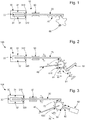
figure 1 , on connait en particulier les moteurs piézoélectriques 10 linéaires pour lesquels l'élément passif est un élément allongé 20 (par exemple une barre à section rectangulaire) et l'actionneur piézoélectrique comporte un résonateur 30 formé d'une paire de bras 31, 32 connectés l'un à l'autre au niveau d'une zone de connexion 33, sensiblement en forme de diapason ou de U. L'actionneur comporte en outre deux éléments piézoélectriques (non représentés), chacun attaché à l'un des bras 31, 32, et jouant le rôle de moyens d'excitation des bras pour leur imposer des vibrations. D'autre part, l'élément passif 20 s'étend sensiblement parallèlement aux bras 31, 32 du résonateur 30, son guidage axial étant assuré par des moyens de guidage 50 se trouvant à distance du résonateur. L'élément passif 20 est également en contact local avec les extrémités libres 310, 320 des bras 31, 32 du résonateur 30, de sorte que l'élément passif 20 soit déplacé axialement par friction des extrémités libres 310, 320 des bras 31, 32 sur la région de contact. - Dans des applications où il est important de réduire l'encombrement du moteur piézoélectrique, en particulier dans le domaine horloger, les bras 31, 32 du résonateur 30 doivent être de faible longueur, ce qui limite la course linéaire maximale de l'élément passif 20. La translation axiale de l'élément passif 20 dans le sens de la zone de connexion 33 est limitée par la présence de ladite zone de connexion 33 qui fait office de butée, et son déplacement axial dans l'autre sens est limitée par la longueur des bras 31, 32. Cette course limitée est problématique dans certaines situations, notamment si l'élément passif 20 engrène avec une roue 60, par exemple par l'intermédiaire d'un système à crémaillère 70, car la rotation de la roue 60 est alors restreinte. A titre d'exemple, si la course de l'élément passif 20 est limitée à environ 1 millimètre, alors le diamètre de la roue 60 doit être au maximum d'environ 0.3 millimètre pour que ladite roue 60 puisse effectuer un tour complet lors de la course. Cette dimension est trop faible pour être réalisable techniquement.
- Le but de la présente invention est de permettre une rotation complète de la roue sans augmenter la course linéaire maximale de l'élément passif.
- A cet effet, selon un premier aspect, l'invention se rapporte à un dispositif de rotation d'une roue dentée, comprenant :
- un moteur piézoélectrique linéaire comprenant :
- un élément passif de forme allongée,
- un actionneur piézoélectrique apte à déplacer axialement l'élément passif de manière bidirectionnelle,
- un organe de transmission solidaire fixé à l'élément passif, en prise avec une denture de la roue de sorte à faire tourner la roue d'une dent selon un premier sens de rotation lorsque l'élément passif est déplacé axialement selon un premier sens de déplacement,
- un sautoir mobile entre deux positions extrémales dont une position abaissée dans laquelle il bloque une rotation de la roue dans un deuxième sens de rotation opposé au premier sens de rotation.
- A chaque déplacement linéaire de l'élément passif dans le premier sens de déplacement réalisé grâce à l'actionneur piézoélectrique, la roue tourne d'une dent dans le premier sens de rotation grâce à l'organe de transmission. A chaque déplacement linéaire de l'élément passif dans un deuxième sens de déplacement opposé au premier réalisé grâce à l'actionneur piézoélectrique, la roue reste immobile grâce au sautoir abaissé. La roue peut donc effectuer un tour complet dans le premier sens de rotation par des mouvements répétés de va et vient de l'élément passif.
- Dans un premier mode de réalisation de l'invention, le dispositif de rotation comprend des moyens de rappel tendant à ramener le sautoir dans la position abaissée lorsque le sautoir en est dévié sous l'effet d'une rotation de la roue dans le premier sens de rotation. Les moyens de rappel sont par exemple des moyens élastiques, permettant de maintenir le sautoir contre la denture de la roue lorsque la roue tourne dans le premier sens de rotation.
- Ce premier mode de réalisation est particulièrement adapté aux roues à rochet. Initialement, le sautoir est en appui dans la denture de la roue à rochet (il est dans la position abaissée). Lorsque l'élément passif se déplace dans la première direction de déplacement, il provoque une rotation de la roue d'une dent selon le premier sens de rotation, par l'intermédiaire de l'organe de transmission qui pousse le rochet de la roue avec lequel il vient en contact. Le sautoir se soulève sous l'effet du passage du rochet de la roue avec lequel il vient en contact, puis reprend sa position abaissée dès que ledit rochet est passé, sous l'effet des moyens de rappel. En revanche, lorsque l'élément passif se déplace dans la deuxième direction de déplacement, une rotation de la roue dans le deuxième sens de rotation empêchée par le sautoir. Ainsi, par des avancées et reculs successifs de l'élément passif, une rotation complète de la roue dans le premier sens de rotation peut être effectuée.
- Dans un deuxième mode de réalisation de l'invention :
- l'organe de transmission est en prise avec la denture de la roue de sorte à faire tourner la roue d'une dent dans le deuxième sens de rotation lorsque l'élément passif est déplacé axialement selon un deuxième sens de déplacement opposé au premier sens de déplacement,
- le sautoir, dans sa position abaissée, bloque une rotation de la roue dans le premier sens de rotation.
- Ce deuxième mode de réalisation est avantageux car il permet, au choix, de faire tourner la roue dans le premier sens de rotation ou alors dans le deuxième sens de rotation. La roue ne peut toutefois pas être à rochet : en effet, l'organe de transmission doit être capable de faire tourner la roue d'une dent dans le deuxième sens de rotation lorsque le sautoir n'est pas en position abaissée et que l'élément passif est déplacé dans le deuxième sens de déplacement. A chaque déplacement axial de l'élément passif dans le deuxième sens de déplacement réalisé grâce à l'actionneur piézoélectrique, la roue tourne d'une dent dans le deuxième sens de rotation grâce à l'organe de transmission. A chaque déplacement linéaire de l'élément passif dans le premier sens de déplacement grâce à l'actionneur piézoélectrique, la roue reste immobile grâce au sautoir abaissé. La roue peut donc effectuer un tour complet dans le deuxième sens de rotation par des mouvements répétés de va et vient de l'élément passif.
- Dans un mode particulier du deuxième mode de réalisation, le dispositif de rotation comporte des moyens d'actionnement permettant de basculer le sautoir d'une position extrémale à l'autre. Les moyens d'actionnement comprennent par exemple un deuxième actionneur piézoélectrique linéaire permettant d'approcher et d'éloigner le sautoir de la roue.
- La position du sautoir est ainsi contrôlée de manière indépendante : la roue ne peut pas déloger le sautoir de la position abaissée comme dans le premier mode de réalisation.
- Dans un mode de réalisation non limitatif, l'actionneur piézoélectrique comporte un résonateur comprenant une paire de bras connectés à l'une de leurs extrémités au niveau d'une zone de connexion, les deux autres extrémités étant dites libres, l'élément passif passant entre les extrémités libres desdits bras de sorte à être déplacé axialement par friction des extrémités libres sur sa surface.
- Un tel actionneur est de faible encombrement, notamment de faible épaisseur, et est facile à fabriquer et à assembler.
- Dans un mode de réalisation, le dispositif de rotation comprend des moyens de guidage axial de l'élément passif tendant à ramener l'élément passif dans sa position initiale lorsque l'élément passif en est dévié sous l'effet d'un déplacement axial de l'élément passif combiné à un blocage en rotation de la roue.
- En effet, lorsque l'élément passif se réarme, c'est-à-dire revient dans sa position initiale après avoir fait tourner la roue d'une dent, il peut se soulever sous l'effet d'un contact entre l'organe de transmission et la prochaine dent que l'organe de transmission devra pousser pour faire tourner à nouveau tourner la roue. Les moyens de guidage permettent d'éviter que l'élément passif ne se désaxe, en le ramenant dans son alignement initial.
- Selon un deuxième aspect, l'invention concerne une pièce d'horlogerie comportant une roue et un dispositif de rotation selon l'un des modes de réalisation présentés précédemment.
- Dans un mode de réalisation, la pièce d'horlogerie comporte une aiguille solidaire en rotation de la roue.
- Selon un troisième aspect, l'invention concerne un procédé de rotation d'une roue dentée au moyen d'un dispositif de rotation selon l'un des modes de réalisation présentés précédemment, comprenant les étapes suivantes successives :
- A : au moyen de l'actionneur piézoélectrique, déplacer axialement l'élément passif dans le premier sens de déplacement,
- B : au moyen de l'organe de transmission, faire tourner la roue d'une dent selon le premier sens de rotation,
- C : placer le sautoir dans la position abaissée,
- D : au moyen de l'actionneur piézoélectrique, déplacer axialement l'élément passif dans le deuxième sens de déplacement.
- Dans un mode de réalisation permettant de faire tourner la roue de plus d'une dent, les étapes A, B, C et D sont répétées autant de fois que nécessaire.
- D'autres particularités et avantages ressortiront clairement de la description qui en est faite ci-après, à titre indicatif et nullement limitatif, en référence aux dessins annexés, dans lesquels :
- la
figure 1 , déjà décrite, représente schématiquement un dispositif de rotation selon l'art antérieur, - la
figure 2 représente schématiquement un dispositif de rotation selon un premier mode de réalisation de l'invention, - la
figure 3 représente schématiquement un dispositif de rotation selon un deuxième mode de réalisation de l'invention, - la
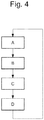
figure 4 représente schématiquement un diagramme fonctionnel des étapes d'un procédé de rotation d'une roue selon un mode de réalisation de l'invention. - La
figure 2 montre un dispositif de rotation 100 d'une roue 61 selon un premier mode de réalisation de l'invention, et lafigure 3 montre un dispositif de rotation 101 d'une roue 62 selon un deuxième mode de réalisation de l'invention. Dans les deux cas, le dispositif de rotation 100, 101 comporte un moteur piézoélectrique. Le moteur piézoélectrique comprend un élément passif 20 de forme allongée, et un actionneur piézoélectrique permettant de mettre en translation (c'est-à-dire déplacer linéairement/axialement) l'élément passif 20 en utilisant l'effet piézoélectrique. - Dans le mode de réalisation illustré, l'actionneur piézoélectrique des moyens d'excitation piézoélectrique, non représentés, et un résonateur 30 comprenant deux bras 31, 32 aptes à osciller. Les moyens d'excitation sont avantageusement constitués de deux parties, chacune attachée à un bras différent. Toutefois, d'autres modes de réalisation des moyens d'excitation sont possibles, ils peuvent par exemple être constitués d'une seule partie disposés au niveau d'une jointure entre les bras. Lors de l'application d'une tension adaptée aux moyens d'excitation, les moyens d'excitation se déforment, et des contraintes mécaniques sont transmises aux bras 31, 32 qui se mettent alors à osciller. Par une conception et un montage appropriés des moyens d'excitation sur les bras, des oscillations multidimensionnelles de forme souhaitée peuvent être réalisées.
- Les bras 31, 32 sont connectés au niveau d'une zone de connexion 33, et s'étendent sensiblement parallèlement l'un à l'autre depuis ladite zone de connexion 33. Le résonateur 30 a donc globalement une forme de diapason, c'est-à-dire une forme de U. Toutefois, cette forme n'est pas limitative. Les extrémités des bras non connectées à la zone de connexion 33, sont dites extrémités libres 310, 320. L'amplitude des oscillations des bras 31, 32 est maximale à ces extrémités 310, 320.
- L'élément passif 20 s'étend sensiblement parallèlement aux bras 31, 32 et passe entre les extrémités libres 310, 320 desdits bras 31, 32. Ainsi, le résonateur 30 encadre une première zone extrémale de l'élément passif 20. Les oscillations multidimensionnelles des extrémités libres 310, 320 des bras 31, 32 permettent d'imposer une translation axiale à l'élément passif 20, par frottement desdites extrémités 310, 320 contre l'élément passif 20. On comprend que la translation dans le sens de la zone de connexion 33 est limitée par ladite zone de connexion 33, et que la translation dans l'autre sens est limitée par la longueur des bras 31, 32.
- On note que l'actionneur piézoélectrique pourrait tout à fait être d'un autre type que celui précédemment décrit, l'important étant qu'il est apte à translater axialement l'élément passif 20 dans un sens de déplacement comme dans l'autre.
- Le dispositif de rotation 100, 101 comporte également des moyens de guidage 50 axial de l'élément passif 20, permettant de maintenir son orientation lors de sa translation. Les moyens de guidage 50 sont placés à distance de l'actionneur piézoélectrique. Il s'agit par exemple d'un rail.
- Le dispositif de rotation comporte également un organe de transmission 71, 72 et un sautoir 81, 82. L'organe de transmission 71, 72 et le sautoir 81, 82 comportent un cran dont la forme est avantageusement adaptée à la denture de la roue. L'organe de transmission 71, 72 est fixé à une deuxième zone extrémale de l'élément passif 20, opposée par rapport à la première zone extrémale. L'organe de transmission 71, 72 est disposé par rapport à la roue de sorte à pouvoir faire tourner la roue dans au moins un sens de rotation lorsque l'élément passif 20 est translaté dans un sens de déplacement sous l'action de l'actionneur piézoélectrique. Le sautoir 81, 82 est mobile entre deux positions extrémales. Dans une de ces positions, dite position abaissée, le sautoir 81, 82 est calé entre deux dents de la roue 61, 62.
- Dans le premier mode de réalisation illustré à la
figure 2 , la roue 61 est une roue à rochet, destinée à ne tourner que dans un premier sens de rotation R1. Une rotation dans le premier sens de rotation R1 n'est possible par l'intermédiaire de l'organe de transmission 71 que lorsque l'élément passif 20 est translaté dans un premier sens de déplacement T1 : l'organe de transmission 71 vient en contact puis pousse un des rochets 610 de la roue 61, faisant tourner la roue 61 d'une dent. - Dans le premier mode de réalisation, le dispositif de rotation 100 comporte des moyens de rappel 91 se présentant sous la forme d'un élément élastique, par exemple un ressort ou une lame, tendant à pousser le sautoir 81 contre les rochets de la roue. Lorsque la roue 61 tourne dans le premier sens de rotation R1, le sautoir 81 est soulevé sous le passage d'une dent, et ramené en position abaissée sous l'effet des moyens de rappel 91, de sorte à suivre sensiblement la forme de la denture. Naturellement, lorsque le sautoir est en position abaissée, la roue à rochet 61 ne peut pas tourner dans un deuxième sens de rotation R2 opposé au premier sens de rotation R1.
- Ainsi, lors d'une translation de l'élément passif 20 dans le sens de déplacement T1, la roue à rochet 61 tourne d'une dent, et lors d'une translation de l'élément passif 20 dans un sens de déplacement T2 opposé au sens de déplacement T1, la roue à rochet 61 est immobilisée par le sautoir 81. En effectuant une pluralité d'allers et retours de l'élément passif 20, il est possible de faire tourner la roue 61 dans le premier sens de rotation R1 d'une pluralité de dents. Une course maximale faible de l'élément passif 20 suffit donc.
- En référence à la
figure 4 , on comprend que le procédé de mise en rotation de la roue 61 au moyen du dispositif de rotation 100 décrit précédemment, comporte les étapes suivantes : - étape A : au moyen de l'actionneur piézoélectrique 30, déplacer axialement l'élément passif 20 dans le premier sens de déplacement,
- étape B : au moyen de l'organe de transmission 71 poussant sur une dent 610 de la roue 61, faire tourner la roue 61 d'une dent selon le premier sens de rotation R1,
- étape D : au moyen de l'actionneur piézoélectrique 30, déplacer axialement l'élément passif 20 dans le deuxième sens de déplacement T2, le sautoir étant maintenu dans la position abaissée par les moyens de rappel 91 (étape C),
- répéter les étapes A, B, C, D autant de fois que nécessaire.
- Dans le deuxième mode de réalisation illustré à la
figure 3 , la roue 62 est à denture classique : elle est conçue pour tourner dans le premier sens de rotation R1 aussi bien que dans le deuxième sens de rotation R2. Une rotation dans le premier sens de rotation R1 est possible par l'intermédiaire de l'organe de transmission 71 lorsque l'élément passif 20 est translaté dans le premier sens de déplacement T1, et une rotation dans le deuxième sens de rotation R2 est possible par l'intermédiaire de l'organe de transmission 71 lorsque l'élément passif 20 est translaté dans le deuxième sens de déplacement T2. - Dans le deuxième mode de réalisation, le dispositif de rotation 100 comporte des moyens d'actionnement 92 se présentant sous la forme d'un deuxième actionneur piézoélectrique linéaire (mais qui pourrait prendre d'autres formes, l'important étant qu'il s'agisse d'un élément actif, contrairement au premier mode de réalisation), apte à commander la position du sautoir 82. Si l'on souhaite faire tourner la roue 62 dans le premier sens de rotation R1, l'organe de transmission 72 doit être déplacé dans le premier sens de déplacement T1 par l'intermédiaire de l'élément passif 20, de sorte à faire tourner la roue 62 d'une dent dans le premier sens de rotation R1. En parallèle, le sautoir 82 doit être en position soulevée, c'est-à-dire qu'il ne doit pas être en contact avec la roue 62 pour ne pas entraver sa rotation. Puis, le sautoir 82 doit être amené en position abaissée, de sorte à bloquer la roue 61, et l'organe de transmission 72 doit être déplacé dans le deuxième sens de déplacement T2 par l'intermédiaire de l'élément passif 20, de sorte à être réarmé. En effectuant une pluralité d'allers et retours de l'élément passif 20, il est possible de faire tourner la roue dans le premier sens de rotation R1 d'une pluralité de dents.
- Au contraire, si l'on souhaite faire tourner la roue 61 dans le deuxième de rotation R2, l'organe de transmission 72 doit être déplacé dans le deuxième sens de déplacement T2 par l'intermédiaire de l'élément passif 20, de sorte à faire tourner la roue 62 d'une dent dans le deuxième sens de rotation R2. En parallèle, le sautoir 82 doit être en position soulevée, c'est-à-dire qu'il ne doit pas être en contact avec la roue 62 pour ne pas entraver sa rotation. Puis, le sautoir 82 doit être amené en position abaissée, de sorte à bloquer la roue 62, et l'organe de transmission 72 doit être déplacé dans le premier sens de déplacement T1 par l'intermédiaire de l'élément passif 20, de sorte à être réarmé. En effectuant une pluralité d'allers et retours de l'élément passif 20, il est possible de faire tourner la roue dans le deuxième sens de rotation R2 d'une pluralité de dents.
- On comprend que le procédé de mise en rotation de la roue 62 au moyen du dispositif de rotation 101 décrit précédemment, comporte les étapes suivantes :
- étape A : au moyen de l'actionneur piézoélectrique 30, déplacer axialement l'élément passif 20 dans un sens de déplacement,
- étape B : au moyen de l'organe de transmission 72 poussant sur une dent 620 de la roue 62, faire tourner la roue 62 d'une dent selon un sens de rotation, le sautoir 82 étant dans la position soulevée,
- étape C : placer le sautoir 82 dans la position abaissée au moyen des moyens d'actionnement 92,
- étape D : au moyen de l'actionneur piézoélectrique 30, déplacer axialement l'élément passif 20 dans un sens de déplacement opposé à celui de l'étape A, le sautoir étant maintenu dans la position abaissée,
- répéter les étapes A, B, C, D autant de fois que nécessaire.
- On note que dans le premier mode de réalisation comme dans le deuxième, le réarmement de l'élément passif 20 est gêné par une dent de la roue 61, 62: lors du réarmement, l'extrémité de l'élément passif 20 portant l'organe de transmission 71, 72 se soulève donc, mais est ramené dans son inclinaison initiale par les moyens de guidage dès que la dent est passée.
- Le dispositif de rotation 100, 101 selon l'un des modes de réalisation de l'invention peut tout à fait être intégré à une pièce d'horlogerie de type montre-bracelet, notamment une pièce d'horlogerie comprenant une aiguille 40 coaxiale avec et solidaire en rotation de la roue 61, 62. Toutefois, le dispositif de rotation selon un des modes de réalisation de l'invention pourrait être utilisé pour entrainer en rotation non pas une aiguille, mais un disque (par exemple un disque des quantièmes ou un disque de phase de lune), une roue ou encore un anneau.
- On comprendra que diverses modifications et/ou améliorations et/ou combinaisons évidentes pour l'homme du métier peuvent être apportées aux différentes formes d'exécution de l'invention exposée ci-dessus sans sortir du cadre de l'invention définie par les revendications annexées.
Claims (12)
- Dispositif de rotation (100 ; 101) d'une roue dentée (61 ; 62), comprenant :- un moteur piézoélectrique linéaire comprenant :• un élément passif (20) de forme allongée,• un actionneur piézoélectrique (30) apte à déplacer axialement l'élément passif (20) de manière bidirectionnelle,- un organe de transmission (71 ; 72) fixé à l'élément passif (20), en prise avec une denture (610 ; 620) de la roue (61 ; 62) de sorte à faire tourner la roue (61 ; 62) d'une dent selon un premier sens de rotation (R1) lorsque l'élément passif (20) est déplacé axialement selon un premier sens de déplacement (T1),- un sautoir (81 ; 82) mobile entre deux positions extrémales dont une position abaissée dans laquelle il bloque une rotation de la roue dans un deuxième sens de rotation (R2) opposé au premier sens de rotation (R1).
- Dispositif de rotation (100) selon la revendication précédente, comprenant des moyens de rappel (91) tendant à ramener le sautoir (81) dans la position abaissée lorsque le sautoir (81) en est dévié sous l'effet d'une rotation de la roue (61) dans le premier sens de rotation (R1).
- Dispositif de rotation (100) selon la revendication précédente, dans lequel les moyens de rappel (91) sont des moyens élastiques, permettant de maintenir le sautoir (82) contre la denture de la roue (61) lorsque la roue tourne dans le premier sens de rotation (R1).
- Dispositif de rotation (101) selon la revendication 1, dans lequel :- l'organe de transmission (72) est en prise avec la denture de la roue (62) de sorte à faire tourner la roue (62) d'une dent dans le deuxième sens de rotation (R2) lorsque l'élément passif (20) est déplacé axialement selon un deuxième sens de déplacement (T2) opposé au premier sens de déplacement (T1),- le sautoir (82), dans sa position abaissée, bloque une rotation de la roue dans le premier sens de rotation (R1).
- Dispositif de rotation (101) selon la revendication précédente, comprenant des moyens d'actionnement (92) permettant de basculer le sautoir (82) d'une position extrémale à l'autre.
- Dispositif de rotation (101) selon la revendication précédente, dans lequel les moyens d'actionnement (92) comprenant un deuxième actionneur piézoélectrique linéaire permettant d'approcher et d'éloigner le sautoir (82) de la roue (62).
- Dispositif de rotation (100 ; 101) selon l'une des revendications précédentes, dans lequel l'actionneur piézoélectrique (30) comporte un résonateur comprenant une paire de bras (31, 32) connectés à l'une de leurs extrémités au niveau d'une zone de connexion (33), les deux autres extrémités (310, 320) étant dites libres, l'élément passif (20) passant entre les extrémités libres (310, 320) desdits bras (31, 32) de sorte à être déplacé axialement par friction des extrémités libres (310, 320) sur sa surface.
- Dispositif de rotation (100 ; 101) selon l'une des revendications précédentes, comprenant des moyens de guidage (50) axial de l'élément passif (20) tendant à ramener l'élément passif (20) dans sa position initiale lorsque l'élément passif (20) en est dévié sous l'effet d'un déplacement axial de l'élément passif (20) combiné à un blocage en rotation de la roue.
- Pièce d'horlogerie comportant une roue (61, 62) et un dispositif de rotation (100 ; 101) selon l'une des revendications précédentes.
- Pièce d'horlogerie selon la revendication précédente, comportant une aiguille (40) solidaire en rotation de la roue (61 ; 62).
- Procédé de rotation d'une roue dentée (61 ; 62) au moyen d'un dispositif de rotation (100 ; 101) selon l'une des revendications 1 à 8, comprenant les étapes suivantes successives :- A : au moyen de l'actionneur piézoélectrique (30), déplacer axialement l'élément passif (20) dans le premier sens de déplacement (T1),- B : au moyen de l'organe de transmission (71 ; 72), faire tourner la roue (61 ; 62) d'une dent selon le premier sens de rotation (R1),- C : placer le sautoir (81 ; 82) dans la position abaissée,- D : au moyen de l'actionneur piézoélectrique (30), déplacer axialement l'élément passif (20) dans le deuxième sens de déplacement (T2).
- Procédé de rotation selon la revendication précédente, comprenant l'étape suivante, réalisée suite à l'étape D : répéter les étapes A, B, C et D.
Priority Applications (5)
| Application Number | Priority Date | Filing Date | Title |
|---|---|---|---|
| EP18160980.1A EP3537593B1 (fr) | 2018-03-09 | 2018-03-09 | Dispositif de rotation d'une roue dentée |
| US16/286,653 US11428298B2 (en) | 2018-03-09 | 2019-02-27 | Device for rotating a toothed wheel |
| JP2019039274A JP6802868B2 (ja) | 2018-03-09 | 2019-03-05 | 歯車を回転させるための機器 |
| CN201910175083.0A CN110244540B (zh) | 2018-03-09 | 2019-03-08 | 用于使有齿的轮旋转的装置 |
| KR1020190027101A KR102269430B1 (ko) | 2018-03-09 | 2019-03-08 | 톱니형 휠을 회전하기 위한 디바이스 |
Applications Claiming Priority (1)
| Application Number | Priority Date | Filing Date | Title |
|---|---|---|---|
| EP18160980.1A EP3537593B1 (fr) | 2018-03-09 | 2018-03-09 | Dispositif de rotation d'une roue dentée |
Publications (2)
| Publication Number | Publication Date |
|---|---|
| EP3537593A1 true EP3537593A1 (fr) | 2019-09-11 |
| EP3537593B1 EP3537593B1 (fr) | 2024-04-24 |
Family
ID=61626925
Family Applications (1)
| Application Number | Title | Priority Date | Filing Date |
|---|---|---|---|
| EP18160980.1A Active EP3537593B1 (fr) | 2018-03-09 | 2018-03-09 | Dispositif de rotation d'une roue dentée |
Country Status (5)
| Country | Link |
|---|---|
| US (1) | US11428298B2 (fr) |
| EP (1) | EP3537593B1 (fr) |
| JP (1) | JP6802868B2 (fr) |
| KR (1) | KR102269430B1 (fr) |
| CN (1) | CN110244540B (fr) |
Families Citing this family (3)
| Publication number | Priority date | Publication date | Assignee | Title |
|---|---|---|---|---|
| JP2023043037A (ja) * | 2021-09-15 | 2023-03-28 | エスゼット ディージェイアイ テクノロジー カンパニー リミテッド | 超音波モータ |
| CN115143382A (zh) * | 2022-08-30 | 2022-10-04 | 山东中艺音美器材有限公司 | 一种音乐用分贝测声仪 |
| DE102023124182B4 (de) * | 2023-09-07 | 2025-04-10 | Anton LEDWON | Getriebe mit Energiespeicher |
Citations (7)
| Publication number | Priority date | Publication date | Assignee | Title |
|---|---|---|---|---|
| US3297889A (en) * | 1964-01-15 | 1967-01-10 | Breskend Sam | Clock driver |
| US3509714A (en) * | 1968-04-25 | 1970-05-05 | Hamilton Watch Co | Electromechanical timepiece |
| FR2034030A5 (fr) * | 1969-02-12 | 1970-12-04 | Philips Nv | |
| US20070029197A1 (en) * | 2005-08-03 | 2007-02-08 | Baker Hughes, Inc. | Downhole uses of electroactive polymers |
| US20070164635A1 (en) * | 2004-06-24 | 2007-07-19 | Miniswys Sa | Drive unit |
| EP2735923A1 (fr) * | 2012-11-23 | 2014-05-28 | ETA SA Manufacture Horlogère Suisse | Mécanisme d'entraînement d'aiguilles d'une montre électro-mécanique, muni d'un dispositif de verrouillage |
| US20160181951A1 (en) * | 2014-12-23 | 2016-06-23 | Max-Planck-Gesellschaft Zur Foerderung Der Wissenschaften E.V. | Ultrasonic actuator device and applications thereof |
Family Cites Families (12)
| Publication number | Priority date | Publication date | Assignee | Title |
|---|---|---|---|---|
| GB1284929A (en) * | 1969-10-21 | 1972-08-09 | Horstmann Gear Co Ltd | Electromechanical motor |
| US3614486A (en) * | 1969-11-10 | 1971-10-19 | Physics Int Co | Lever motion multiplier driven by electroexpansive material |
| CH1553471A4 (fr) * | 1971-09-27 | 1975-12-31 | ||
| US4871939A (en) * | 1987-12-21 | 1989-10-03 | Emhart Industries, Inc. | Piezoelectric motor |
| DE19942269A1 (de) * | 1999-09-04 | 2001-03-08 | Philips Corp Intellectual Pty | Piezoelektrische Antriebsvorrichtung |
| ATE370519T1 (de) * | 1999-11-29 | 2007-09-15 | Miniswys Sa | Piezoelektrischer antrieb |
| US7119478B1 (en) * | 2004-02-11 | 2006-10-10 | Honeywell Federal Manufacturing & Technologies, Llc | Piezoelectric step-motion actuator |
| JP2008306826A (ja) * | 2007-06-07 | 2008-12-18 | Seiko Epson Corp | 圧電アクチュエータ及びその駆動方法 |
| EP2596406B1 (fr) * | 2010-07-19 | 2019-03-27 | Nivarox-FAR S.A. | Mecanisme oscillant a pivot elastique et mobile de transmission d'energie |
| EP2503410B1 (fr) | 2011-03-22 | 2014-05-21 | Montres Breguet SA | Mecanisme de calendrier comportant un correcteur rapide de mois |
| JP5780261B2 (ja) | 2013-04-24 | 2015-09-16 | カシオ計算機株式会社 | アクチュエータ |
| CN203835235U (zh) | 2014-05-24 | 2014-09-17 | 宁波市鄞州荣利金属制品有限公司 | 扭簧防断裂装置 |
-
2018
- 2018-03-09 EP EP18160980.1A patent/EP3537593B1/fr active Active
-
2019
- 2019-02-27 US US16/286,653 patent/US11428298B2/en active Active
- 2019-03-05 JP JP2019039274A patent/JP6802868B2/ja active Active
- 2019-03-08 CN CN201910175083.0A patent/CN110244540B/zh active Active
- 2019-03-08 KR KR1020190027101A patent/KR102269430B1/ko active Active
Patent Citations (7)
| Publication number | Priority date | Publication date | Assignee | Title |
|---|---|---|---|---|
| US3297889A (en) * | 1964-01-15 | 1967-01-10 | Breskend Sam | Clock driver |
| US3509714A (en) * | 1968-04-25 | 1970-05-05 | Hamilton Watch Co | Electromechanical timepiece |
| FR2034030A5 (fr) * | 1969-02-12 | 1970-12-04 | Philips Nv | |
| US20070164635A1 (en) * | 2004-06-24 | 2007-07-19 | Miniswys Sa | Drive unit |
| US20070029197A1 (en) * | 2005-08-03 | 2007-02-08 | Baker Hughes, Inc. | Downhole uses of electroactive polymers |
| EP2735923A1 (fr) * | 2012-11-23 | 2014-05-28 | ETA SA Manufacture Horlogère Suisse | Mécanisme d'entraînement d'aiguilles d'une montre électro-mécanique, muni d'un dispositif de verrouillage |
| US20160181951A1 (en) * | 2014-12-23 | 2016-06-23 | Max-Planck-Gesellschaft Zur Foerderung Der Wissenschaften E.V. | Ultrasonic actuator device and applications thereof |
Also Published As
| Publication number | Publication date |
|---|---|
| CN110244540A (zh) | 2019-09-17 |
| KR102269430B1 (ko) | 2021-06-25 |
| JP6802868B2 (ja) | 2020-12-23 |
| JP2019162021A (ja) | 2019-09-19 |
| KR20190106813A (ko) | 2019-09-18 |
| CN110244540B (zh) | 2021-03-12 |
| EP3537593B1 (fr) | 2024-04-24 |
| US11428298B2 (en) | 2022-08-30 |
| US20190277376A1 (en) | 2019-09-12 |
Similar Documents
| Publication | Publication Date | Title |
|---|---|---|
| EP3499319B1 (fr) | Bascule d'embrayage et dispositif d'embrayage pour mecanisme horloger | |
| EP3537593B1 (fr) | Dispositif de rotation d'une roue dentée | |
| EP2407830B1 (fr) | Piece d'horlogerie | |
| CH709508A2 (fr) | Mouvement horloger muni d'un mécanisme d'entraînement d'un indicateur analogique à déplacement périodique ou intermittent. | |
| EP2864167B1 (fr) | Servofrein electrique a compensation de jeu de transmission | |
| EP2798413B1 (fr) | Ressort pour mouvement horloger | |
| EP3489766B1 (fr) | Mécanisme de correction d'une fonction d'un mouvement d'une pièce d'horlogerie | |
| CH714734A2 (fr) | Dispositif de rotation d’une roue dentée. | |
| EP2177960B1 (fr) | Mécanisme de blocage pour module d'entraînement horloger | |
| EP3763030A1 (fr) | Moteur piezoélectrique linéaire à course allongée | |
| CH720212B1 (fr) | Mouvement horloger comprenant un module de liaison cinématique interposé entre un dispositif de sélection et de commande de fonctions et un dispositif d'affichage | |
| EP2515185B1 (fr) | Moteur à moment de force constant | |
| EP2735923B1 (fr) | Mécanisme d'entraînement d'aiguilles d'une montre électro-mécanique, muni d'un dispositif de verrouillage | |
| FR3060091A1 (fr) | Dispositif de blocage mecanique d'un arbre de transmission d'un vehicule automobile | |
| EP1960846B1 (fr) | Mouvement d'horlogerie | |
| EP3537232A1 (fr) | Moteur piezoélectrique rotatif pour disque | |
| CH714735A2 (fr) | Moteur piézoélectrique linéaire à course allongée. | |
| EP3845973A1 (fr) | Mécanisme horloger destiné à être entrainé suivant un nombre de pas variable | |
| CH714372A2 (fr) | Mécanisme de correction d'une fonction d'un mouvement d'une pièce d'horlogerie. | |
| CH719095A2 (fr) | Moteur piézoélectrique rotatif à précontrainte axiale. | |
| CH702996A1 (fr) | Engrenage. | |
| WO2025012315A1 (fr) | Méthode d'entretien des oscillations d'un oscillateur d'une pièce d'horlogerie | |
| EP4495707A1 (fr) | Mécanisme d'un mouvement horloger comprenant un dispositif de blocage d'un mobile | |
| WO2025016871A1 (fr) | Mécanisme d'un mouvement horloger comprenant un dispositif de blocage d'un mobile | |
| EP4163732A1 (fr) | Mécanisme horloger d'embrayage |
Legal Events
| Date | Code | Title | Description |
|---|---|---|---|
| PUAI | Public reference made under article 153(3) epc to a published international application that has entered the european phase |
Free format text: ORIGINAL CODE: 0009012 |
|
| STAA | Information on the status of an ep patent application or granted ep patent |
Free format text: STATUS: THE APPLICATION HAS BEEN PUBLISHED |
|
| AK | Designated contracting states |
Kind code of ref document: A1 Designated state(s): AL AT BE BG CH CY CZ DE DK EE ES FI FR GB GR HR HU IE IS IT LI LT LU LV MC MK MT NL NO PL PT RO RS SE SI SK SM TR |
|
| AX | Request for extension of the european patent |
Extension state: BA ME |
|
| STAA | Information on the status of an ep patent application or granted ep patent |
Free format text: STATUS: REQUEST FOR EXAMINATION WAS MADE |
|
| 17P | Request for examination filed |
Effective date: 20200311 |
|
| RBV | Designated contracting states (corrected) |
Designated state(s): AL AT BE BG CH CY CZ DE DK EE ES FI FR GB GR HR HU IE IS IT LI LT LU LV MC MK MT NL NO PL PT RO RS SE SI SK SM TR |
|
| P01 | Opt-out of the competence of the unified patent court (upc) registered |
Effective date: 20230701 |
|
| GRAP | Despatch of communication of intention to grant a patent |
Free format text: ORIGINAL CODE: EPIDOSNIGR1 |
|
| STAA | Information on the status of an ep patent application or granted ep patent |
Free format text: STATUS: GRANT OF PATENT IS INTENDED |
|
| RIC1 | Information provided on ipc code assigned before grant |
Ipc: G04C 3/12 20060101ALI20231124BHEP Ipc: G04B 11/02 20060101ALI20231124BHEP Ipc: H02N 2/04 20060101ALI20231124BHEP Ipc: H02N 2/02 20060101AFI20231124BHEP |
|
| INTG | Intention to grant announced |
Effective date: 20231212 |
|
| GRAS | Grant fee paid |
Free format text: ORIGINAL CODE: EPIDOSNIGR3 |
|
| GRAA | (expected) grant |
Free format text: ORIGINAL CODE: 0009210 |
|
| STAA | Information on the status of an ep patent application or granted ep patent |
Free format text: STATUS: THE PATENT HAS BEEN GRANTED |
|
| AK | Designated contracting states |
Kind code of ref document: B1 Designated state(s): AL AT BE BG CH CY CZ DE DK EE ES FI FR GB GR HR HU IE IS IT LI LT LU LV MC MK MT NL NO PL PT RO RS SE SI SK SM TR |
|
| REG | Reference to a national code |
Ref country code: GB Ref legal event code: FG4D Free format text: NOT ENGLISH |
|
| REG | Reference to a national code |
Ref country code: CH Ref legal event code: EP |
|
| REG | Reference to a national code |
Ref country code: DE Ref legal event code: R096 Ref document number: 602018068441 Country of ref document: DE |
|
| REG | Reference to a national code |
Ref country code: IE Ref legal event code: FG4D Free format text: LANGUAGE OF EP DOCUMENT: FRENCH |
|
| REG | Reference to a national code |
Ref country code: LT Ref legal event code: MG9D |
|
| REG | Reference to a national code |
Ref country code: NL Ref legal event code: MP Effective date: 20240424 |
|
| REG | Reference to a national code |
Ref country code: AT Ref legal event code: MK05 Ref document number: 1680700 Country of ref document: AT Kind code of ref document: T Effective date: 20240424 |
|
| PG25 | Lapsed in a contracting state [announced via postgrant information from national office to epo] |
Ref country code: NL Free format text: LAPSE BECAUSE OF FAILURE TO SUBMIT A TRANSLATION OF THE DESCRIPTION OR TO PAY THE FEE WITHIN THE PRESCRIBED TIME-LIMIT Effective date: 20240424 |
|
| PG25 | Lapsed in a contracting state [announced via postgrant information from national office to epo] |
Ref country code: NL Free format text: LAPSE BECAUSE OF FAILURE TO SUBMIT A TRANSLATION OF THE DESCRIPTION OR TO PAY THE FEE WITHIN THE PRESCRIBED TIME-LIMIT Effective date: 20240424 |
|
| PG25 | Lapsed in a contracting state [announced via postgrant information from national office to epo] |
Ref country code: IS Free format text: LAPSE BECAUSE OF FAILURE TO SUBMIT A TRANSLATION OF THE DESCRIPTION OR TO PAY THE FEE WITHIN THE PRESCRIBED TIME-LIMIT Effective date: 20240824 |
|
| PG25 | Lapsed in a contracting state [announced via postgrant information from national office to epo] |
Ref country code: BG Free format text: LAPSE BECAUSE OF FAILURE TO SUBMIT A TRANSLATION OF THE DESCRIPTION OR TO PAY THE FEE WITHIN THE PRESCRIBED TIME-LIMIT Effective date: 20240424 |
|
| PG25 | Lapsed in a contracting state [announced via postgrant information from national office to epo] |
Ref country code: HR Free format text: LAPSE BECAUSE OF FAILURE TO SUBMIT A TRANSLATION OF THE DESCRIPTION OR TO PAY THE FEE WITHIN THE PRESCRIBED TIME-LIMIT Effective date: 20240424 Ref country code: FI Free format text: LAPSE BECAUSE OF FAILURE TO SUBMIT A TRANSLATION OF THE DESCRIPTION OR TO PAY THE FEE WITHIN THE PRESCRIBED TIME-LIMIT Effective date: 20240424 |
|
| PG25 | Lapsed in a contracting state [announced via postgrant information from national office to epo] |
Ref country code: GR Free format text: LAPSE BECAUSE OF FAILURE TO SUBMIT A TRANSLATION OF THE DESCRIPTION OR TO PAY THE FEE WITHIN THE PRESCRIBED TIME-LIMIT Effective date: 20240725 |
|
| PG25 | Lapsed in a contracting state [announced via postgrant information from national office to epo] |
Ref country code: PT Free format text: LAPSE BECAUSE OF FAILURE TO SUBMIT A TRANSLATION OF THE DESCRIPTION OR TO PAY THE FEE WITHIN THE PRESCRIBED TIME-LIMIT Effective date: 20240826 |
|
| PG25 | Lapsed in a contracting state [announced via postgrant information from national office to epo] |
Ref country code: ES Free format text: LAPSE BECAUSE OF FAILURE TO SUBMIT A TRANSLATION OF THE DESCRIPTION OR TO PAY THE FEE WITHIN THE PRESCRIBED TIME-LIMIT Effective date: 20240424 |
|
| PG25 | Lapsed in a contracting state [announced via postgrant information from national office to epo] |
Ref country code: AT Free format text: LAPSE BECAUSE OF FAILURE TO SUBMIT A TRANSLATION OF THE DESCRIPTION OR TO PAY THE FEE WITHIN THE PRESCRIBED TIME-LIMIT Effective date: 20240424 |
|
| PG25 | Lapsed in a contracting state [announced via postgrant information from national office to epo] |
Ref country code: PL Free format text: LAPSE BECAUSE OF FAILURE TO SUBMIT A TRANSLATION OF THE DESCRIPTION OR TO PAY THE FEE WITHIN THE PRESCRIBED TIME-LIMIT Effective date: 20240424 |
|
| PG25 | Lapsed in a contracting state [announced via postgrant information from national office to epo] |
Ref country code: LV Free format text: LAPSE BECAUSE OF FAILURE TO SUBMIT A TRANSLATION OF THE DESCRIPTION OR TO PAY THE FEE WITHIN THE PRESCRIBED TIME-LIMIT Effective date: 20240424 |
|
| PG25 | Lapsed in a contracting state [announced via postgrant information from national office to epo] |
Ref country code: PT Free format text: LAPSE BECAUSE OF FAILURE TO SUBMIT A TRANSLATION OF THE DESCRIPTION OR TO PAY THE FEE WITHIN THE PRESCRIBED TIME-LIMIT Effective date: 20240826 Ref country code: PL Free format text: LAPSE BECAUSE OF FAILURE TO SUBMIT A TRANSLATION OF THE DESCRIPTION OR TO PAY THE FEE WITHIN THE PRESCRIBED TIME-LIMIT Effective date: 20240424 Ref country code: NO Free format text: LAPSE BECAUSE OF FAILURE TO SUBMIT A TRANSLATION OF THE DESCRIPTION OR TO PAY THE FEE WITHIN THE PRESCRIBED TIME-LIMIT Effective date: 20240724 Ref country code: LV Free format text: LAPSE BECAUSE OF FAILURE TO SUBMIT A TRANSLATION OF THE DESCRIPTION OR TO PAY THE FEE WITHIN THE PRESCRIBED TIME-LIMIT Effective date: 20240424 Ref country code: IS Free format text: LAPSE BECAUSE OF FAILURE TO SUBMIT A TRANSLATION OF THE DESCRIPTION OR TO PAY THE FEE WITHIN THE PRESCRIBED TIME-LIMIT Effective date: 20240824 Ref country code: HR Free format text: LAPSE BECAUSE OF FAILURE TO SUBMIT A TRANSLATION OF THE DESCRIPTION OR TO PAY THE FEE WITHIN THE PRESCRIBED TIME-LIMIT Effective date: 20240424 Ref country code: GR Free format text: LAPSE BECAUSE OF FAILURE TO SUBMIT A TRANSLATION OF THE DESCRIPTION OR TO PAY THE FEE WITHIN THE PRESCRIBED TIME-LIMIT Effective date: 20240725 Ref country code: FI Free format text: LAPSE BECAUSE OF FAILURE TO SUBMIT A TRANSLATION OF THE DESCRIPTION OR TO PAY THE FEE WITHIN THE PRESCRIBED TIME-LIMIT Effective date: 20240424 Ref country code: ES Free format text: LAPSE BECAUSE OF FAILURE TO SUBMIT A TRANSLATION OF THE DESCRIPTION OR TO PAY THE FEE WITHIN THE PRESCRIBED TIME-LIMIT Effective date: 20240424 Ref country code: BG Free format text: LAPSE BECAUSE OF FAILURE TO SUBMIT A TRANSLATION OF THE DESCRIPTION OR TO PAY THE FEE WITHIN THE PRESCRIBED TIME-LIMIT Effective date: 20240424 Ref country code: AT Free format text: LAPSE BECAUSE OF FAILURE TO SUBMIT A TRANSLATION OF THE DESCRIPTION OR TO PAY THE FEE WITHIN THE PRESCRIBED TIME-LIMIT Effective date: 20240424 Ref country code: RS Free format text: LAPSE BECAUSE OF FAILURE TO SUBMIT A TRANSLATION OF THE DESCRIPTION OR TO PAY THE FEE WITHIN THE PRESCRIBED TIME-LIMIT Effective date: 20240724 |
|
| PG25 | Lapsed in a contracting state [announced via postgrant information from national office to epo] |
Ref country code: DK Free format text: LAPSE BECAUSE OF FAILURE TO SUBMIT A TRANSLATION OF THE DESCRIPTION OR TO PAY THE FEE WITHIN THE PRESCRIBED TIME-LIMIT Effective date: 20240424 |
|
| PG25 | Lapsed in a contracting state [announced via postgrant information from national office to epo] |
Ref country code: EE Free format text: LAPSE BECAUSE OF FAILURE TO SUBMIT A TRANSLATION OF THE DESCRIPTION OR TO PAY THE FEE WITHIN THE PRESCRIBED TIME-LIMIT Effective date: 20240424 |
|
| PG25 | Lapsed in a contracting state [announced via postgrant information from national office to epo] |
Ref country code: CZ Free format text: LAPSE BECAUSE OF FAILURE TO SUBMIT A TRANSLATION OF THE DESCRIPTION OR TO PAY THE FEE WITHIN THE PRESCRIBED TIME-LIMIT Effective date: 20240424 |
|
| PG25 | Lapsed in a contracting state [announced via postgrant information from national office to epo] |
Ref country code: RO Free format text: LAPSE BECAUSE OF FAILURE TO SUBMIT A TRANSLATION OF THE DESCRIPTION OR TO PAY THE FEE WITHIN THE PRESCRIBED TIME-LIMIT Effective date: 20240424 Ref country code: SK Free format text: LAPSE BECAUSE OF FAILURE TO SUBMIT A TRANSLATION OF THE DESCRIPTION OR TO PAY THE FEE WITHIN THE PRESCRIBED TIME-LIMIT Effective date: 20240424 |
|
| REG | Reference to a national code |
Ref country code: DE Ref legal event code: R097 Ref document number: 602018068441 Country of ref document: DE |
|
| PG25 | Lapsed in a contracting state [announced via postgrant information from national office to epo] |
Ref country code: SM Free format text: LAPSE BECAUSE OF FAILURE TO SUBMIT A TRANSLATION OF THE DESCRIPTION OR TO PAY THE FEE WITHIN THE PRESCRIBED TIME-LIMIT Effective date: 20240424 |
|
| PG25 | Lapsed in a contracting state [announced via postgrant information from national office to epo] |
Ref country code: SM Free format text: LAPSE BECAUSE OF FAILURE TO SUBMIT A TRANSLATION OF THE DESCRIPTION OR TO PAY THE FEE WITHIN THE PRESCRIBED TIME-LIMIT Effective date: 20240424 Ref country code: SK Free format text: LAPSE BECAUSE OF FAILURE TO SUBMIT A TRANSLATION OF THE DESCRIPTION OR TO PAY THE FEE WITHIN THE PRESCRIBED TIME-LIMIT Effective date: 20240424 Ref country code: RO Free format text: LAPSE BECAUSE OF FAILURE TO SUBMIT A TRANSLATION OF THE DESCRIPTION OR TO PAY THE FEE WITHIN THE PRESCRIBED TIME-LIMIT Effective date: 20240424 Ref country code: EE Free format text: LAPSE BECAUSE OF FAILURE TO SUBMIT A TRANSLATION OF THE DESCRIPTION OR TO PAY THE FEE WITHIN THE PRESCRIBED TIME-LIMIT Effective date: 20240424 Ref country code: DK Free format text: LAPSE BECAUSE OF FAILURE TO SUBMIT A TRANSLATION OF THE DESCRIPTION OR TO PAY THE FEE WITHIN THE PRESCRIBED TIME-LIMIT Effective date: 20240424 Ref country code: CZ Free format text: LAPSE BECAUSE OF FAILURE TO SUBMIT A TRANSLATION OF THE DESCRIPTION OR TO PAY THE FEE WITHIN THE PRESCRIBED TIME-LIMIT Effective date: 20240424 |
|
| PLBE | No opposition filed within time limit |
Free format text: ORIGINAL CODE: 0009261 |
|
| STAA | Information on the status of an ep patent application or granted ep patent |
Free format text: STATUS: NO OPPOSITION FILED WITHIN TIME LIMIT |
|
| 26N | No opposition filed |
Effective date: 20250127 |
|
| PG25 | Lapsed in a contracting state [announced via postgrant information from national office to epo] |
Ref country code: SI Free format text: LAPSE BECAUSE OF FAILURE TO SUBMIT A TRANSLATION OF THE DESCRIPTION OR TO PAY THE FEE WITHIN THE PRESCRIBED TIME-LIMIT Effective date: 20240424 |
|
| PGFP | Annual fee paid to national office [announced via postgrant information from national office to epo] |
Ref country code: CH Payment date: 20250401 Year of fee payment: 8 |
|
| PG25 | Lapsed in a contracting state [announced via postgrant information from national office to epo] |
Ref country code: SE Free format text: LAPSE BECAUSE OF FAILURE TO SUBMIT A TRANSLATION OF THE DESCRIPTION OR TO PAY THE FEE WITHIN THE PRESCRIBED TIME-LIMIT Effective date: 20240424 |
|
| PG25 | Lapsed in a contracting state [announced via postgrant information from national office to epo] |
Ref country code: MC Free format text: LAPSE BECAUSE OF FAILURE TO SUBMIT A TRANSLATION OF THE DESCRIPTION OR TO PAY THE FEE WITHIN THE PRESCRIBED TIME-LIMIT Effective date: 20240424 |
|
| PG25 | Lapsed in a contracting state [announced via postgrant information from national office to epo] |
Ref country code: LU Free format text: LAPSE BECAUSE OF NON-PAYMENT OF DUE FEES Effective date: 20250309 |
|
| REG | Reference to a national code |
Ref country code: BE Ref legal event code: MM Effective date: 20250331 |
|
| PG25 | Lapsed in a contracting state [announced via postgrant information from national office to epo] |
Ref country code: BE Free format text: LAPSE BECAUSE OF NON-PAYMENT OF DUE FEES Effective date: 20250331 |
|
| PG25 | Lapsed in a contracting state [announced via postgrant information from national office to epo] |
Ref country code: IE Free format text: LAPSE BECAUSE OF NON-PAYMENT OF DUE FEES Effective date: 20250309 |
|
| PG25 | Lapsed in a contracting state [announced via postgrant information from national office to epo] |
Ref country code: IT Free format text: LAPSE BECAUSE OF FAILURE TO SUBMIT A TRANSLATION OF THE DESCRIPTION OR TO PAY THE FEE WITHIN THE PRESCRIBED TIME-LIMIT Effective date: 20240424 |
|
| REG | Reference to a national code |
Ref country code: CH Ref legal event code: U11 Free format text: ST27 STATUS EVENT CODE: U-0-0-U10-U11 (AS PROVIDED BY THE NATIONAL OFFICE) Effective date: 20260401 |
|
| PGFP | Annual fee paid to national office [announced via postgrant information from national office to epo] |
Ref country code: GB Payment date: 20260220 Year of fee payment: 9 |
|
| PGFP | Annual fee paid to national office [announced via postgrant information from national office to epo] |
Ref country code: DE Payment date: 20260219 Year of fee payment: 9 |
|
| PGFP | Annual fee paid to national office [announced via postgrant information from national office to epo] |
Ref country code: FR Payment date: 20260220 Year of fee payment: 9 |