EP3537510A1 - Battery module and battery pack including same - Google Patents
Battery module and battery pack including same Download PDFInfo
- Publication number
- EP3537510A1 EP3537510A1 EP18828675.1A EP18828675A EP3537510A1 EP 3537510 A1 EP3537510 A1 EP 3537510A1 EP 18828675 A EP18828675 A EP 18828675A EP 3537510 A1 EP3537510 A1 EP 3537510A1
- Authority
- EP
- European Patent Office
- Prior art keywords
- operation body
- battery module
- battery
- pivoting
- bus bar
- Prior art date
- Legal status (The legal status is an assumption and is not a legal conclusion. Google has not performed a legal analysis and makes no representation as to the accuracy of the status listed.)
- Pending
Links
Images



Classifications
-
- H—ELECTRICITY
- H01—ELECTRIC ELEMENTS
- H01M—PROCESSES OR MEANS, e.g. BATTERIES, FOR THE DIRECT CONVERSION OF CHEMICAL ENERGY INTO ELECTRICAL ENERGY
- H01M50/00—Constructional details or processes of manufacture of the non-active parts of electrochemical cells other than fuel cells, e.g. hybrid cells
- H01M50/50—Current conducting connections for cells or batteries
- H01M50/572—Means for preventing undesired use or discharge
- H01M50/574—Devices or arrangements for the interruption of current
- H01M50/578—Devices or arrangements for the interruption of current in response to pressure
-
- H—ELECTRICITY
- H01—ELECTRIC ELEMENTS
- H01M—PROCESSES OR MEANS, e.g. BATTERIES, FOR THE DIRECT CONVERSION OF CHEMICAL ENERGY INTO ELECTRICAL ENERGY
- H01M50/00—Constructional details or processes of manufacture of the non-active parts of electrochemical cells other than fuel cells, e.g. hybrid cells
- H01M50/20—Mountings; Secondary casings or frames; Racks, modules or packs; Suspension devices; Shock absorbers; Transport or carrying devices; Holders
- H01M50/204—Racks, modules or packs for multiple batteries or multiple cells
- H01M50/207—Racks, modules or packs for multiple batteries or multiple cells characterised by their shape
- H01M50/211—Racks, modules or packs for multiple batteries or multiple cells characterised by their shape adapted for pouch cells
-
- H—ELECTRICITY
- H01—ELECTRIC ELEMENTS
- H01M—PROCESSES OR MEANS, e.g. BATTERIES, FOR THE DIRECT CONVERSION OF CHEMICAL ENERGY INTO ELECTRICAL ENERGY
- H01M50/00—Constructional details or processes of manufacture of the non-active parts of electrochemical cells other than fuel cells, e.g. hybrid cells
- H01M50/50—Current conducting connections for cells or batteries
- H01M50/502—Interconnectors for connecting terminals of adjacent batteries; Interconnectors for connecting cells outside a battery casing
- H01M50/505—Interconnectors for connecting terminals of adjacent batteries; Interconnectors for connecting cells outside a battery casing comprising a single busbar
-
- H—ELECTRICITY
- H01—ELECTRIC ELEMENTS
- H01M—PROCESSES OR MEANS, e.g. BATTERIES, FOR THE DIRECT CONVERSION OF CHEMICAL ENERGY INTO ELECTRICAL ENERGY
- H01M50/00—Constructional details or processes of manufacture of the non-active parts of electrochemical cells other than fuel cells, e.g. hybrid cells
- H01M50/50—Current conducting connections for cells or batteries
- H01M50/572—Means for preventing undesired use or discharge
- H01M50/584—Means for preventing undesired use or discharge for preventing incorrect connections inside or outside the batteries
- H01M50/588—Means for preventing undesired use or discharge for preventing incorrect connections inside or outside the batteries outside the batteries, e.g. incorrect connections of terminals or busbars
-
- B—PERFORMING OPERATIONS; TRANSPORTING
- B60—VEHICLES IN GENERAL
- B60K—ARRANGEMENT OR MOUNTING OF PROPULSION UNITS OR OF TRANSMISSIONS IN VEHICLES; ARRANGEMENT OR MOUNTING OF PLURAL DIVERSE PRIME-MOVERS IN VEHICLES; AUXILIARY DRIVES FOR VEHICLES; INSTRUMENTATION OR DASHBOARDS FOR VEHICLES; ARRANGEMENTS IN CONNECTION WITH COOLING, AIR INTAKE, GAS EXHAUST OR FUEL SUPPLY OF PROPULSION UNITS IN VEHICLES
- B60K6/00—Arrangement or mounting of plural diverse prime-movers for mutual or common propulsion, e.g. hybrid propulsion systems comprising electric motors and internal combustion engines
- B60K6/20—Arrangement or mounting of plural diverse prime-movers for mutual or common propulsion, e.g. hybrid propulsion systems comprising electric motors and internal combustion engines the prime-movers consisting of electric motors and internal combustion engines, e.g. HEVs
- B60K6/22—Arrangement or mounting of plural diverse prime-movers for mutual or common propulsion, e.g. hybrid propulsion systems comprising electric motors and internal combustion engines the prime-movers consisting of electric motors and internal combustion engines, e.g. HEVs characterised by apparatus, components or means specially adapted for HEVs
- B60K6/28—Arrangement or mounting of plural diverse prime-movers for mutual or common propulsion, e.g. hybrid propulsion systems comprising electric motors and internal combustion engines the prime-movers consisting of electric motors and internal combustion engines, e.g. HEVs characterised by apparatus, components or means specially adapted for HEVs characterised by the electric energy storing means, e.g. batteries or capacitors
-
- B—PERFORMING OPERATIONS; TRANSPORTING
- B60—VEHICLES IN GENERAL
- B60L—PROPULSION OF ELECTRICALLY-PROPELLED VEHICLES; SUPPLYING ELECTRIC POWER FOR AUXILIARY EQUIPMENT OF ELECTRICALLY-PROPELLED VEHICLES; ELECTRODYNAMIC BRAKE SYSTEMS FOR VEHICLES IN GENERAL; MAGNETIC SUSPENSION OR LEVITATION FOR VEHICLES; MONITORING OPERATING VARIABLES OF ELECTRICALLY-PROPELLED VEHICLES; ELECTRIC SAFETY DEVICES FOR ELECTRICALLY-PROPELLED VEHICLES
- B60L50/00—Electric propulsion with power supplied within the vehicle
- B60L50/50—Electric propulsion with power supplied within the vehicle using propulsion power supplied by batteries or fuel cells
- B60L50/60—Electric propulsion with power supplied within the vehicle using propulsion power supplied by batteries or fuel cells using power supplied by batteries
- B60L50/64—Constructional details of batteries specially adapted for electric vehicles
-
- B—PERFORMING OPERATIONS; TRANSPORTING
- B60—VEHICLES IN GENERAL
- B60Y—INDEXING SCHEME RELATING TO ASPECTS CROSS-CUTTING VEHICLE TECHNOLOGY
- B60Y2200/00—Type of vehicle
- B60Y2200/90—Vehicles comprising electric prime movers
- B60Y2200/91—Electric vehicles
-
- B—PERFORMING OPERATIONS; TRANSPORTING
- B60—VEHICLES IN GENERAL
- B60Y—INDEXING SCHEME RELATING TO ASPECTS CROSS-CUTTING VEHICLE TECHNOLOGY
- B60Y2200/00—Type of vehicle
- B60Y2200/90—Vehicles comprising electric prime movers
- B60Y2200/92—Hybrid vehicles
-
- B—PERFORMING OPERATIONS; TRANSPORTING
- B60—VEHICLES IN GENERAL
- B60Y—INDEXING SCHEME RELATING TO ASPECTS CROSS-CUTTING VEHICLE TECHNOLOGY
- B60Y2400/00—Special features of vehicle units
- B60Y2400/11—Electric energy storages
- B60Y2400/112—Batteries
-
- H—ELECTRICITY
- H01—ELECTRIC ELEMENTS
- H01M—PROCESSES OR MEANS, e.g. BATTERIES, FOR THE DIRECT CONVERSION OF CHEMICAL ENERGY INTO ELECTRICAL ENERGY
- H01M2200/00—Safety devices for primary or secondary batteries
- H01M2200/20—Pressure-sensitive devices
-
- H—ELECTRICITY
- H01—ELECTRIC ELEMENTS
- H01M—PROCESSES OR MEANS, e.g. BATTERIES, FOR THE DIRECT CONVERSION OF CHEMICAL ENERGY INTO ELECTRICAL ENERGY
- H01M2220/00—Batteries for particular applications
- H01M2220/20—Batteries in motive systems, e.g. vehicle, ship, plane
-
- Y—GENERAL TAGGING OF NEW TECHNOLOGICAL DEVELOPMENTS; GENERAL TAGGING OF CROSS-SECTIONAL TECHNOLOGIES SPANNING OVER SEVERAL SECTIONS OF THE IPC; TECHNICAL SUBJECTS COVERED BY FORMER USPC CROSS-REFERENCE ART COLLECTIONS [XRACs] AND DIGESTS
- Y02—TECHNOLOGIES OR APPLICATIONS FOR MITIGATION OR ADAPTATION AGAINST CLIMATE CHANGE
- Y02E—REDUCTION OF GREENHOUSE GAS [GHG] EMISSIONS, RELATED TO ENERGY GENERATION, TRANSMISSION OR DISTRIBUTION
- Y02E60/00—Enabling technologies; Technologies with a potential or indirect contribution to GHG emissions mitigation
- Y02E60/10—Energy storage using batteries
-
- Y—GENERAL TAGGING OF NEW TECHNOLOGICAL DEVELOPMENTS; GENERAL TAGGING OF CROSS-SECTIONAL TECHNOLOGIES SPANNING OVER SEVERAL SECTIONS OF THE IPC; TECHNICAL SUBJECTS COVERED BY FORMER USPC CROSS-REFERENCE ART COLLECTIONS [XRACs] AND DIGESTS
- Y02—TECHNOLOGIES OR APPLICATIONS FOR MITIGATION OR ADAPTATION AGAINST CLIMATE CHANGE
- Y02T—CLIMATE CHANGE MITIGATION TECHNOLOGIES RELATED TO TRANSPORTATION
- Y02T10/00—Road transport of goods or passengers
- Y02T10/60—Other road transportation technologies with climate change mitigation effect
- Y02T10/70—Energy storage systems for electromobility, e.g. batteries
Definitions
- the present disclosure relates to a battery module and a battery pack including the battery module, and more particularly, to a battery module capable of preventing the overcharge of a battery cell and a battery pack including the battery module.
- a nickel-cadmium battery or a hydrogen ion battery has been used as the secondary battery.
- a lithium secondary battery is recently widely used because charging and discharging is free due to rare memory effect in comparison with a nickel-based secondary battery, a self-discharge rate is very low, and an energy density is high.
- the lithium secondary battery mainly uses a lithium oxide and a carbonaceous material as a positive electrode active material and a negative electrode active material, respectively.
- the lithium secondary battery includes an electrode assembly in which a positive electrode plate and a negative electrode plate, respectively coated with the positive electrode active material and the negative electrode active material, are arranged with a separator therebetween, and an outer member, that is a battery case, which seals and receives the electrode assembly together with an electrolyte solution.
- the lithium secondary battery includes a positive electrode, a negative electrode, and a separator interposed therebetween and an electrolyte.
- the lithium secondary battery is classified into a lithium ion battery (LIB) and a polymer lithium ion battery (PLIB).
- LIB lithium ion battery
- PKIB polymer lithium ion battery
- an electrode of the lithium secondary battery is prepared by applying the positive or negative electrode active material to a current collector made of aluminum or copper sheet, mesh, film, foil, or the like and then drying the same.
- the present disclosure is directed to providing a battery module capable of preventing the overcharge of a battery cell regardless of a BMS, such as when an error occurs in the BMS, and a battery pack including the battery module.
- the present disclosure is directed to providing a battery module capable of preventing the overcharge of a battery cell by using the pressure generated when the overcharge occurs at the battery cell, and a battery pack including battery module.
- a battery module comprising: a battery cell stack having a plurality of battery cells stacked; a bus bar configured to electrically connect electrode leads respectively provided at the plurality of battery cells; and a breaking unit disposed between the plurality of battery cells to be spaced apart from the bus bar and configured to operate by a gas pressure of gas generated in the battery cells to break the electric connection between the electrode lead and the bus bar.
- the breaking unit may include: an operation body having a holding portion, a first elastic member being coupled to the operation body; and a fixing member hooked to the holding portion of the operation body to fix the operation body in a state where the operation body is elastically contracted by the first elastic member, a second elastic member being coupled to the fixing member so that the operation body keeps the fixed state.
- the battery module may further comprise a fracture member coupled to the operation body to face the bus bar and having a sharp tip portion formed to face the bus bar.
- a fracture groove may be formed at the bus bar, and the sharp tip portion of the fracture member may be disposed to face the fracture groove of the bus bar.
- a first inclined portion may be formed at the holding portion of the operation body to be inclined upwards from an inside of the operation body toward an outside thereof, and the first elastic member may be coupled to a lower side of a center of the operation body.
- the fixing member may include: a pivoting portion having a second inclined portion corresponding to the first inclined portion to contact the first inclined portion of the holding portion, the second elastic member being coupled to the pivoting portion; and a pivotal shaft coupled to the pivoting portion.
- the pivoting portion may include a first pivoting portion at which the second inclined portion is formed and to which the second elastic member is coupled; and a second pivoting portion extending from the first pivoting portion and pressed by the battery cells.
- the pivoting portion may be provided in a pair, and the pair of pivoting portions may be respectively disposed at both sides of the operation body so that the operation body is disposed between the pair of pivoting portions.
- a first inclined portion may be formed at the holding portion of the operation body to be inclined downward from an inside of the operation body toward an outside thereof, and the first elastic member may be respectively coupled to lower sides of both ends of the operation body.
- the fixing member may include: a pivoting portion having a second inclined portion corresponding to the first inclined portion to contact the first inclined portion of the holding portion, the second elastic member being coupled to the pivoting portion; and a pivotal shaft coupled to the pivoting portion.
- the pivoting portion may include a first pivoting portion at which the second inclined portion is formed; and a second pivoting portion extending from the first pivoting portion, coupled with the second elastic member and pressed by the battery cells.
- the pivoting portion may be provided in a pair, and the pair of pivoting portions may be disposed to cross each other at the pivotal shaft on the basis of the pivotal shaft.
- the battery module may further comprise a support member disposed between the plurality of battery cells so that the breaking unit is supported in contact with the support member.
- the breaking unit may be installed at a terrace portion at which the electrode lead of the battery cell is disposed and supported.
- a battery pack including the battery module described above, and there is also provided a vehicle including the battery module.
- a breaking unit for breaking electric connection between the electrode lead and the bus bar operates when the battery cell is overcharged, it is possible to prevent the overcharge of the battery cell regardless of a BMS, such as when the BMS malfunctions and thus it is impossible or difficult to control the overcharge.
- the force is stored in the elastic member elastically contracted and the pressure generated when the battery cell is overcharged may act as a trigger of the elastic member, it is possible to prevent the overcharge of the battery cell.
- 'combine' or 'connect' may refer not only to a case where one member and another member are directly combined or directly connected but also a case where one member is indirectly combined with another member via a connecting member or is indirectly connected.
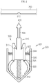
- FIG. 1 is a cross-sectioned view showing a portion of a battery module according to the first embodiment of the present disclosure
- FIGS. 2 and 3 are diagrams for illustrating an operating process of a breaking unit at the battery module according to the first embodiment of the present disclosure.
- a battery module according to the first embodiment of the present disclosure includes a battery cell stack 100, a bus bar 200 and a breaking unit 300.
- the battery cell stack 100 may be configured so that a plurality of battery cells 110 are stacked therein (see FIG. 1 ).
- the battery cells 110 may have various structures, and the plurality of unit cells 110 may be stacked in various ways.
- the battery cell 110 may be configured so that a plurality of unit cells, in each of which a positive electrode plate, a separator and a negative electrode plate are arranged in order, or a plurality of bi-cells, in each of which a positive electrode plate, a separator, a negative electrode plate, a separator, a positive electrode plate, a separator and a negative electrode plate are arranged in order, are stacked suitable for a battery capacity.
- the battery cell 110 may have an electrode lead 111.
- the electrode lead 111 is a type of terminal that is exposed to the outside and connected to an external device and may be made of a conductive material.
- the electrode lead 111 may include a positive electrode lead and a negative electrode lead.
- the positive electrode lead and the negative electrode lead may be disposed in opposite directions with respect to the longitudinal direction of the battery cell 110, or the positive electrode lead and the negative electrode lead may be positioned in the same direction with respect to the longitudinal direction of the battery cell 110.
- the electrode lead 111 may be electrically coupled to the bus bar 200, explained later.
- the breaking unit 300 may be installed at the terrace portion 600 which is swollen by the gas collected in the gas collector (not shown) at overcharge. That is, the breaking unit 300 may be operated by the gas pressure applied to the breaking unit 300 at the terrace portion 600.
- the case of the battery cell 110 may have various types. For convenience of explanation, the case of the battery cell 110 will be described as a pouch-type case.
- the battery cell stack 100 may include a plurality of cartridges (not shown) for accommodating the battery cells 110.
- Each cartridge (not shown) may be fabricated by injection-molding plastic, and a plurality of cartridges (not shown) having an accommodation portion for accommodating the battery cell 110 may be stacked.
- a cartridge assembly in which a plurality of cartridges (not shown) are stacked may include a connector element or a terminal element.
- the connector element may include various types of electrical connecting components or connecting components for connecting to, for example, a battery management system (BMS) (not shown) capable of providing data on voltage or temperature of the battery cells 110.
- BMS battery management system
- the terminal element includes a positive electrode terminal and a negative electrode terminal as main terminals connected to the battery cell 110, and the terminal element may have a terminal bolt to be electrically connected to the outside.
- the battery cell 110 may have various shapes.
- the bus bar 200 is coupled to the electrode leads 111 respectively provided at the plurality of battery cells 110 to electrically connect the electrode leads 111.
- the electric connection may include serial or parallel connection.
- the bus bar 200 and the electrode lead 111 may be connected in various ways, for example by welding.
- a fracture groove 210 may be formed at the bus bar 200 so that the bus bar 200 may be easily fractured when an overcharge occurs at the battery cell 110. This will be described in detail later.
- the support member 500 is disposed between the plurality of battery cells 110, and the breaking unit 300 may be supported in contact with the support member 500. That is, referring to FIG. 1 , the support member 500 may be coupled to the terrace portion 600 between one battery cell 110 and another battery cell 110 adjacent to one battery cell 110, and the breaking unit 300, explained later, may be coupled to and supported by the support member 500.
- the support member 500 may be configured in various manners, for example an interconnector provided at the battery module.
- the interconnector is disposed around the battery cells 110 and transmits an electric signal corresponding to the temperature of the battery cell 110 or an electric signal corresponding to the current or voltage of the battery cell 110 to the BMS while the battery cell is repeatedly charged or discharged.
- the breaking unit 300 may be coupled to the interconnector.
- the support member 500 does not necessarily have to be an interconnector.
- the breaking unit 300 is provided to operate by the gas pressure of the gas generated in the battery cell 110 when the battery cell 110 is charged or discharged, or particularly overcharged. That is, if the gas is generated in the case of the battery cell 110 as described above, the gas is collected in the gas collector (not shown) disposed near the terrace portion 600 where the electrode lead 111 of the battery cell 110 is provided and supported, and thus the breaking unit 300 may be disposed between the plurality of battery cells 110 at a location close to the terrace portion 600 where the gas collector (not shown) is located, at this time to be spaced apart from the bus bar 200. However, if the gas collector (not shown) is away from the terrace portion 600, the position of the breaking unit 300 may be changed to be adjacent to the gas collector (not shown).
- the breaking unit 300 may operate by the gas pressure of the gas generated when the battery cell 110 is overcharged, to break the electrical connection between the electrode lead 111 and the bus bar 200. By doing so, it is possible to prevent the overcharge of the battery cell 110 regardless of the BMS.
- the breaking unit 300 may include an operation body 310 and a fixing member 320.
- a holding portion 311 may be formed at the operation body 310 and a first elastic member 312 may be coupled thereto.
- the fixing member 320 is hooked to the holding portion 311 of the operation body 310 to fix the operation body 310 so that the operation body 310 may keep elastically contracted by the first elastic member 312.
- a second elastic member 324 is coupled to the fixing member 320 so that the fixing member 320 keeps hooked to the holding portion 311 of the operation body 310 and fixed to the operation body 310.
- the operation body 310 coupled to the first elastic member 312 in a state where the first elastic member 312 is elastically contracted is hooked and fixed to the fixing member 320.
- the operation body 310 is hooked and fixed to the fixing member 320 in a state where the first elastic member 312 is elastically contracted.
- the gas pressure is transmitted to the fixing member 320 of the breaking unit 300, so that the fixing member 320 pivots while overcoming the elastic force of the second elastic member 324. If so, the operation body 310 hooked to the fixing member 320 is released, so that the operation body 310 is fired toward the bus bar 200 due to the elastic recovery force of the first elastic member 312.
- a fracture member 400 may be coupled to the operation body 310. That is, the fracture member 400 may be coupled to the operation body 310 to face the bus bar 200 and have a sharp tip portion 410 facing the bus bar 200.
- the fracture member 400 having the sharp tip portion 410 may collide with the bus bar 200 to fracture the bus bar 200 itself or the connection portion between the bus bar 200 and the electrode lead 111.
- the operation body 310 may collide with the bus bar 200 to fracture the bus bar 200 itself or the connection portion between the bus bar 200 and the electrode lead 111.
- the fracture groove 210 may be formed at the bus bar 200 so that the bus bar 200 itself may be easily fractured.
- the fracture groove 210 may have various shapes or various sizes. If the fracture groove 210 is formed at the bus bar 200, the sharp tip portion 410 of the fracture member 400 may be disposed to face the fracture groove 210 of the bus bar 200. That is, if the operation body 310 is fired, the sharp tip portion 410 of the fracture member 400 may collide with the fracture groove 210 of the bus bar (see FIG. 3 ) to fracture the bus bar 200 about the fracture groove 210 of the bus bar 200.
- the hooked portion 311 of the operation body 310 may have a first inclined portion 315 that is inclined upwards from the inside of the operation body 310 toward the outside thereof.
- the first inclined portion 315 may be formed to be hooked to a second inclined portion 323 formed at the pivoting portion 321 of the fixing member 320.
- the first elastic member 312 is coupled to a lower side of the center of the operation body 310 and the holding portion 311 of the operation body 310 is hooked and fixed to the fixing member 320 in a state where the first elastic member 312 is elastically contracted.
- the fixing member 320 may include a pivoting portion 321 and a pivotal shaft 326.
- the pivoting portion 321 may include a first pivoting portion 322 at which the second inclined portion 323 corresponding to the first inclined portion 315 to contact the first inclined portion 315 of the holding portion 311 is formed and to which the second elastic member 324 is coupled, and a second pivoting portion 325 extending from the first pivoting portion 322 and pressed by the battery cell 110. That is, since the second inclined portion 323 of the fixing member 320 is hooked to the first inclined portion 315 formed at the holding portion 311 of the operation body 310 in a state where the first elastic member 312 is elastically contracted, the operation body 310 is fixed as shown in FIG. 2 .
- first elastic member 312 may be in contact with the support member 500.
- the pivoting portion 321 may be provided in a pair, and the pair of pivoting portions 321 may be disposed at both sides of the operation body 310, respectively. By doing so, the operation body 310 may be disposed between the pair of pivoting portions 321.
- the second elastic member 324 and the second pivoting portion 325 may contact the support member 500.
- the pivotal shaft 326 may be coupled to the pivoting portion 321. That is, the pivoting portion 321 may pivot relative to the pivotal shaft 326.
- the operation body 310 is fired toward the bus bar 200 due to the elastic recovery force of the first elastic member 312, and the sharp tip portion 410 of the fracture member 400 coupled to the operation body 310 collides with the fracture groove 210 of the bar 200 and fractures the bus bar 200, or the operation body 310 to the fracture member 400 collides with the bus bar 200 to break the electrical connection between the bus bar 200 and the electrode lead 111.
- the breaking unit 300 is disposed between the plurality of battery cells 110, and the operation body 310 of the breaking unit 300 is fixed by the fixing member 320 in a state where the first elastic member 312 is elastically contracted.
- the second inclined portion 323 is formed at the first pivoting portion 322 of the fixing member 320, and the second inclined portion 323 is hooked to the first inclined portion 315 formed at the holding portion 311 of the operation body 310, thereby fixing the operation body 310.
- the pivoting portion 321 of the fixing member 320 pivots based on the pivotal shaft 326 due to the gas pressure, and if the pivoting portion 321 pivots, the operation body 310 is released and thus fired.
- the operation body 310 collides with the bus bar 200, or the fracture member 400 coupled to the operation body 310 collides with the bus bar 200, thereby fracturing the bus bar 200 itself or fracturing the connection portion between the bus bar 200 and the electrode lead 111 to prevent the battery cell 110 from being overcharged.
- the battery module according to the first embodiment of the present disclosure uses the first elastic member 312 and the second elastic member 324, it is possible to amplify the force as great as fracturing the bus bar 200 itself or the connection portion between the bus bar 200 and the electrode lead 111.
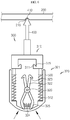
- FIG. 4 is a cross-sectioned view showing a portion of a battery module according to the second embodiment of the present disclosure
- FIGS. 5 and 6 are diagrams for illustrating an operating process of a breaking unit at the battery module according to the second embodiment of the present disclosure.
- the second embodiment of the present disclosure is different from the first embodiment in the point that the detailed shape of the breaking unit 300 is different.
- the first inclined portion 315 is formed at the holding portion 311 of the operation body 310 so as to be inclined downward from the inside of the operation body 310 toward the outside thereof, and the first elastic member 312 may be coupled to lower sides of both ends of the operation body 310, respectively.
- the first elastic member 312 may be elastically contracted in contact with the support member 500, similar to the first embodiment.
- the fixing member 320 may include a pivoting portion 321 and a pivotal shaft 326.
- the pivoting portion 321 may include a second inclined portion 323 corresponding to the first inclined portion 315 to be in contact with the first inclined portion 315 of the holding portion 311, and the second elastic member 324 may be coupled thereto.
- the pivoting portion 321 may include a first pivoting portion 322 at which the second inclined portion 323 is formed, and a second pivoting portion 325 extending from the first pivoting portion 322, coupled with the second elastic member 324 and pressed by the battery cell 110.
- the pivoting portion 321 may be provided in a pair, similar to the first embodiment, but its structure is different from that of the first embodiment. Referring to FIGS. 5 and 6 , the pair of pivoting portions 321 may be disposed to cross each other at the pivotal shaft 326 on the basis of the pivotal shaft 326.
- the basic operation of the breaking unit 300 according to the second embodiment is common to that of the breaking unit 300 of the first embodiment, and thus a detailed description thereof is replaced with that of the first embodiment.
- a battery pack (not shown) according to an embodiment of the present disclosure, may include one or more battery modules according to an embodiment of the present disclosure as described above. Also, in addition to the battery modules, the battery pack (not shown) may further includes a case for accommodating the battery modules, and various devices for controlling charge and discharge of the battery modules, such as a BMS, a current sensor, a fuse, and the like.
- a vehicle (not shown) may include the battery module or the battery pack (not shown) described above, and the battery pack (not shown) may include the battery module.
- the battery module according to an embodiment of the present disclosure may be applied to the vehicle (not shown), for example, a predetermined vehicle (not shown) provided to use electricity like an electric vehicle or a hybrid electric vehicle.
- the present disclosure is directed to a battery module and a battery pack including the battery module and is particularly applicable to industries associated with a secondary battery.
Landscapes
- Chemical & Material Sciences (AREA)
- Chemical Kinetics & Catalysis (AREA)
- Electrochemistry (AREA)
- General Chemical & Material Sciences (AREA)
- Connection Of Batteries Or Terminals (AREA)
- Battery Mounting, Suspending (AREA)
Abstract
Description
- The present application claims priority to Korean Patent Application No.
10-2017-0085992 filed on July 6, 2017 - The present disclosure relates to a battery module and a battery pack including the battery module, and more particularly, to a battery module capable of preventing the overcharge of a battery cell and a battery pack including the battery module.
- As technology development and demand for a mobile device have increased, demand for a secondary battery as an energy source has rapidly increased. Conventionally, a nickel-cadmium battery or a hydrogen ion battery has been used as the secondary battery. However, a lithium secondary battery is recently widely used because charging and discharging is free due to rare memory effect in comparison with a nickel-based secondary battery, a self-discharge rate is very low, and an energy density is high.
- The lithium secondary battery mainly uses a lithium oxide and a carbonaceous material as a positive electrode active material and a negative electrode active material, respectively. The lithium secondary battery includes an electrode assembly in which a positive electrode plate and a negative electrode plate, respectively coated with the positive electrode active material and the negative electrode active material, are arranged with a separator therebetween, and an outer member, that is a battery case, which seals and receives the electrode assembly together with an electrolyte solution.
- The lithium secondary battery includes a positive electrode, a negative electrode, and a separator interposed therebetween and an electrolyte. Depending on which material is used for the positive electrode active material and the negative electrode active material, the lithium secondary battery is classified into a lithium ion battery (LIB) and a polymer lithium ion battery (PLIB). Generally, an electrode of the lithium secondary battery is prepared by applying the positive or negative electrode active material to a current collector made of aluminum or copper sheet, mesh, film, foil, or the like and then drying the same.
- In relation to the conventional battery module, there is known a technique of preventing overcharge based on a voltage and breaking a voltage through a battery management system (BMS) when the voltage measured by a sensor is an overvoltage. However, this conventional technique has a problem because overcharge cannot be prevented when the BMS operates abnormally.
- The present disclosure is directed to providing a battery module capable of preventing the overcharge of a battery cell regardless of a BMS, such as when an error occurs in the BMS, and a battery pack including the battery module.
- In addition, the present disclosure is directed to providing a battery module capable of preventing the overcharge of a battery cell by using the pressure generated when the overcharge occurs at the battery cell, and a battery pack including battery module.
- In one aspect of the present disclosure, there is provided a battery module, comprising: a battery cell stack having a plurality of battery cells stacked; a bus bar configured to electrically connect electrode leads respectively provided at the plurality of battery cells; and a breaking unit disposed between the plurality of battery cells to be spaced apart from the bus bar and configured to operate by a gas pressure of gas generated in the battery cells to break the electric connection between the electrode lead and the bus bar.
- Also, the breaking unit may include: an operation body having a holding portion, a first elastic member being coupled to the operation body; and a fixing member hooked to the holding portion of the operation body to fix the operation body in a state where the operation body is elastically contracted by the first elastic member, a second elastic member being coupled to the fixing member so that the operation body keeps the fixed state.
- In addition, the battery module may further comprise a fracture member coupled to the operation body to face the bus bar and having a sharp tip portion formed to face the bus bar.
- Also, a fracture groove may be formed at the bus bar, and the sharp tip portion of the fracture member may be disposed to face the fracture groove of the bus bar.
- In addition, a first inclined portion may be formed at the holding portion of the operation body to be inclined upwards from an inside of the operation body toward an outside thereof, and the first elastic member may be coupled to a lower side of a center of the operation body.
- Also, the fixing member may include: a pivoting portion having a second inclined portion corresponding to the first inclined portion to contact the first inclined portion of the holding portion, the second elastic member being coupled to the pivoting portion; and a pivotal shaft coupled to the pivoting portion.
- In addition, the pivoting portion may include a first pivoting portion at which the second inclined portion is formed and to which the second elastic member is coupled; and a second pivoting portion extending from the first pivoting portion and pressed by the battery cells.
- Also, the pivoting portion may be provided in a pair, and the pair of pivoting portions may be respectively disposed at both sides of the operation body so that the operation body is disposed between the pair of pivoting portions.
- In addition, a first inclined portion may be formed at the holding portion of the operation body to be inclined downward from an inside of the operation body toward an outside thereof, and the first elastic member may be respectively coupled to lower sides of both ends of the operation body.
- Also, the fixing member may include: a pivoting portion having a second inclined portion corresponding to the first inclined portion to contact the first inclined portion of the holding portion, the second elastic member being coupled to the pivoting portion; and a pivotal shaft coupled to the pivoting portion.
- In addition, the pivoting portion may include a first pivoting portion at which the second inclined portion is formed; and a second pivoting portion extending from the first pivoting portion, coupled with the second elastic member and pressed by the battery cells.
- Also, the pivoting portion may be provided in a pair, and the pair of pivoting portions may be disposed to cross each other at the pivotal shaft on the basis of the pivotal shaft.
- In addition, the battery module may further comprise a support member disposed between the plurality of battery cells so that the breaking unit is supported in contact with the support member.
- Also, the breaking unit may be installed at a terrace portion at which the electrode lead of the battery cell is disposed and supported.
- Meanwhile, in another aspect of the present disclosure, there is also provided a battery pack including the battery module described above, and there is also provided a vehicle including the battery module.
- According to the embodiments of the present disclosure, since a breaking unit for breaking electric connection between the electrode lead and the bus bar operates when the battery cell is overcharged, it is possible to prevent the overcharge of the battery cell regardless of a BMS, such as when the BMS malfunctions and thus it is impossible or difficult to control the overcharge.
- In addition, since the force is stored in the elastic member elastically contracted and the pressure generated when the battery cell is overcharged may act as a trigger of the elastic member, it is possible to prevent the overcharge of the battery cell.
-
-
FIG. 1 is a cross-sectioned view showing a portion of a battery module according to the first embodiment of the present disclosure. -
FIGS. 2 and3 are diagrams for illustrating an operating process of a breaking unit at the battery module according to the first embodiment of the present disclosure. -
FIG. 4 is a cross-sectioned view showing a portion of a battery module according to the second embodiment of the present disclosure. -
FIGS. 5 and6 are diagrams for illustrating an operating process of a breaking unit at the battery module according to the second embodiment of the present disclosure. - Hereinafter, preferred embodiments of the present disclosure will be described in detail with reference to the accompanying drawings. Prior to the description, it should be understood that the terms used in the specification and the appended claims should not be construed as limited to general and dictionary meanings, but interpreted based on the meanings and concepts corresponding to technical aspects of the present disclosure on the basis of the principle that the inventor is allowed to define terms appropriately for the best explanation. Therefore, the description proposed herein is just a preferable example for the purpose of illustrations only, not intended to limit the scope of the disclosure, so it should be understood that other equivalents and modifications could be made thereto without departing from the scope of the disclosure.
- In the drawings, the size of each element or a specific part of the element may be exaggerated, omitted, or schematically illustrated for convenience and clarity of a description. Thus, the size of each element does not entirely reflect the actual size of the element. A detailed description of well-known functions or elements associated with the present disclosure will be omitted if it unnecessarily obscures the subject matter of the present disclosure.
- The term, 'combine' or 'connect' as used herein, may refer not only to a case where one member and another member are directly combined or directly connected but also a case where one member is indirectly combined with another member via a connecting member or is indirectly connected.
-
FIG. 1 is a cross-sectioned view showing a portion of a battery module according to the first embodiment of the present disclosure, andFIGS. 2 and3 are diagrams for illustrating an operating process of a breaking unit at the battery module according to the first embodiment of the present disclosure. - Referring to
FIGS. 1 to 3 , a battery module according to the first embodiment of the present disclosure includes abattery cell stack 100, abus bar 200 and abreaking unit 300. - The
battery cell stack 100 may be configured so that a plurality ofbattery cells 110 are stacked therein (seeFIG. 1 ). Thebattery cells 110 may have various structures, and the plurality ofunit cells 110 may be stacked in various ways. Thebattery cell 110 may be configured so that a plurality of unit cells, in each of which a positive electrode plate, a separator and a negative electrode plate are arranged in order, or a plurality of bi-cells, in each of which a positive electrode plate, a separator, a negative electrode plate, a separator, a positive electrode plate, a separator and a negative electrode plate are arranged in order, are stacked suitable for a battery capacity. - The
battery cell 110 may have anelectrode lead 111. Theelectrode lead 111 is a type of terminal that is exposed to the outside and connected to an external device and may be made of a conductive material. Theelectrode lead 111 may include a positive electrode lead and a negative electrode lead. The positive electrode lead and the negative electrode lead may be disposed in opposite directions with respect to the longitudinal direction of thebattery cell 110, or the positive electrode lead and the negative electrode lead may be positioned in the same direction with respect to the longitudinal direction of thebattery cell 110. Theelectrode lead 111 may be electrically coupled to thebus bar 200, explained later. If thebattery cell 110 is charged or discharged, gas is generated inside the case of thebattery cell 110, and the gas may be collected in a gas collector (not shown) disposed near aterrace portion 600 where theelectrode lead 111 of thebattery cell 110 is provided and supported. Also, thebreaking unit 300 may be installed at theterrace portion 600 which is swollen by the gas collected in the gas collector (not shown) at overcharge. That is, the breakingunit 300 may be operated by the gas pressure applied to the breakingunit 300 at theterrace portion 600. The case of thebattery cell 110 may have various types. For convenience of explanation, the case of thebattery cell 110 will be described as a pouch-type case. - The
battery cell stack 100 may include a plurality of cartridges (not shown) for accommodating thebattery cells 110. Each cartridge (not shown) may be fabricated by injection-molding plastic, and a plurality of cartridges (not shown) having an accommodation portion for accommodating thebattery cell 110 may be stacked. A cartridge assembly in which a plurality of cartridges (not shown) are stacked may include a connector element or a terminal element. The connector element may include various types of electrical connecting components or connecting components for connecting to, for example, a battery management system (BMS) (not shown) capable of providing data on voltage or temperature of thebattery cells 110. In addition, the terminal element includes a positive electrode terminal and a negative electrode terminal as main terminals connected to thebattery cell 110, and the terminal element may have a terminal bolt to be electrically connected to the outside. Meanwhile, thebattery cell 110 may have various shapes. - The
bus bar 200 is coupled to the electrode leads 111 respectively provided at the plurality ofbattery cells 110 to electrically connect the electrode leads 111. Here, the electric connection may include serial or parallel connection. Thebus bar 200 and theelectrode lead 111 may be connected in various ways, for example by welding. Afracture groove 210 may be formed at thebus bar 200 so that thebus bar 200 may be easily fractured when an overcharge occurs at thebattery cell 110. This will be described in detail later. - The
support member 500 is disposed between the plurality ofbattery cells 110, and thebreaking unit 300 may be supported in contact with thesupport member 500. That is, referring toFIG. 1 , thesupport member 500 may be coupled to theterrace portion 600 between onebattery cell 110 and anotherbattery cell 110 adjacent to onebattery cell 110, and thebreaking unit 300, explained later, may be coupled to and supported by thesupport member 500. Here, thesupport member 500 may be configured in various manners, for example an interconnector provided at the battery module. Here, the interconnector is disposed around thebattery cells 110 and transmits an electric signal corresponding to the temperature of thebattery cell 110 or an electric signal corresponding to the current or voltage of thebattery cell 110 to the BMS while the battery cell is repeatedly charged or discharged. In the present disclosure, thebreaking unit 300 may be coupled to the interconnector. However, thesupport member 500 does not necessarily have to be an interconnector. - The
breaking unit 300 is provided to operate by the gas pressure of the gas generated in thebattery cell 110 when thebattery cell 110 is charged or discharged, or particularly overcharged. That is, if the gas is generated in the case of thebattery cell 110 as described above, the gas is collected in the gas collector (not shown) disposed near theterrace portion 600 where theelectrode lead 111 of thebattery cell 110 is provided and supported, and thus thebreaking unit 300 may be disposed between the plurality ofbattery cells 110 at a location close to theterrace portion 600 where the gas collector (not shown) is located, at this time to be spaced apart from thebus bar 200. However, if the gas collector (not shown) is away from theterrace portion 600, the position of thebreaking unit 300 may be changed to be adjacent to the gas collector (not shown). Also, thebreaking unit 300 may operate by the gas pressure of the gas generated when thebattery cell 110 is overcharged, to break the electrical connection between theelectrode lead 111 and thebus bar 200. By doing so, it is possible to prevent the overcharge of thebattery cell 110 regardless of the BMS. - The
breaking unit 300 may include anoperation body 310 and a fixingmember 320. Referring toFIGS. 2 and3 , a holdingportion 311 may be formed at theoperation body 310 and a firstelastic member 312 may be coupled thereto. The fixingmember 320 is hooked to the holdingportion 311 of theoperation body 310 to fix theoperation body 310 so that theoperation body 310 may keep elastically contracted by the firstelastic member 312. Here, a secondelastic member 324 is coupled to the fixingmember 320 so that the fixingmember 320 keeps hooked to the holdingportion 311 of theoperation body 310 and fixed to theoperation body 310. Here, theoperation body 310 coupled to the firstelastic member 312 in a state where the firstelastic member 312 is elastically contracted is hooked and fixed to the fixingmember 320. That is, referring toFIGS. 1 and2 , theoperation body 310 is hooked and fixed to the fixingmember 320 in a state where the firstelastic member 312 is elastically contracted. In addition, if gas is generated in thebattery cell 110 due to overcharge, the gas pressure is transmitted to the fixingmember 320 of thebreaking unit 300, so that the fixingmember 320 pivots while overcoming the elastic force of the secondelastic member 324. If so, theoperation body 310 hooked to the fixingmember 320 is released, so that theoperation body 310 is fired toward thebus bar 200 due to the elastic recovery force of the firstelastic member 312. Due to the firing force of theoperation body 310, theoperation body 310 collides with thebus bar 200 to fracture thebus bar 200 or fracture a connecting portion of thebus bar 200 and theelectrode lead 111. To this end, afracture member 400 may be coupled to theoperation body 310. That is, thefracture member 400 may be coupled to theoperation body 310 to face thebus bar 200 and have asharp tip portion 410 facing thebus bar 200. Here, if theoperation body 310 is fired, thefracture member 400 having thesharp tip portion 410 may collide with thebus bar 200 to fracture thebus bar 200 itself or the connection portion between thebus bar 200 and theelectrode lead 111. If thefracture member 400 is not provided and only theoperation body 310 is provided, theoperation body 310 may collide with thebus bar 200 to fracture thebus bar 200 itself or the connection portion between thebus bar 200 and theelectrode lead 111. Thefracture groove 210 may be formed at thebus bar 200 so that thebus bar 200 itself may be easily fractured. Thefracture groove 210 may have various shapes or various sizes. If thefracture groove 210 is formed at thebus bar 200, thesharp tip portion 410 of thefracture member 400 may be disposed to face thefracture groove 210 of thebus bar 200. That is, if theoperation body 310 is fired, thesharp tip portion 410 of thefracture member 400 may collide with thefracture groove 210 of the bus bar (seeFIG. 3 ) to fracture thebus bar 200 about thefracture groove 210 of thebus bar 200. - Referring to
FIGS. 2 and3 , the hookedportion 311 of theoperation body 310 may have a firstinclined portion 315 that is inclined upwards from the inside of theoperation body 310 toward the outside thereof. Here, the firstinclined portion 315 may be formed to be hooked to a secondinclined portion 323 formed at the pivotingportion 321 of the fixingmember 320. In addition, the firstelastic member 312 is coupled to a lower side of the center of theoperation body 310 and the holdingportion 311 of theoperation body 310 is hooked and fixed to the fixingmember 320 in a state where the firstelastic member 312 is elastically contracted. - The fixing
member 320 may include a pivotingportion 321 and apivotal shaft 326. The pivotingportion 321 may include afirst pivoting portion 322 at which the secondinclined portion 323 corresponding to the firstinclined portion 315 to contact the firstinclined portion 315 of the holdingportion 311 is formed and to which the secondelastic member 324 is coupled, and asecond pivoting portion 325 extending from thefirst pivoting portion 322 and pressed by thebattery cell 110. That is, since the secondinclined portion 323 of the fixingmember 320 is hooked to the firstinclined portion 315 formed at the holdingportion 311 of theoperation body 310 in a state where the firstelastic member 312 is elastically contracted, theoperation body 310 is fixed as shown inFIG. 2 . In addition, the firstelastic member 312 may be in contact with thesupport member 500. Here, the pivotingportion 321 may be provided in a pair, and the pair of pivotingportions 321 may be disposed at both sides of theoperation body 310, respectively. By doing so, theoperation body 310 may be disposed between the pair of pivotingportions 321. Here, the secondelastic member 324 and thesecond pivoting portion 325 may contact thesupport member 500. Thepivotal shaft 326 may be coupled to the pivotingportion 321. That is, the pivotingportion 321 may pivot relative to thepivotal shaft 326. Namely, if gas is generated due to the overcharge of thebattery cell 110, gas pressure is generated near theterrace portion 600 of thebattery cell 110, so that the gas pressure is applied to thesecond pivoting portion 325 to press thesecond pivoting portion 325. In addition, if thesecond pivoting portion 325 pivots relative to thepivotal shaft 326, thefirst pivoting portion 322 extending from thesecond pivoting portion 325 also pivots, and the secondinclined portion 323 of thefirst pivoting portion 322 moves along the firstinclined portion 321 of the holdingportion 311 of theoperation body 310. If the secondinclined portion 323 moves and is released from the firstinclined portion 315, theoperation body 310 is fired toward thebus bar 200 due to the elastic recovery force of the firstelastic member 312, and thesharp tip portion 410 of thefracture member 400 coupled to theoperation body 310 collides with thefracture groove 210 of thebar 200 and fractures thebus bar 200, or theoperation body 310 to thefracture member 400 collides with thebus bar 200 to break the electrical connection between thebus bar 200 and theelectrode lead 111. - Hereinafter, the operation and effect of the battery module according to the first embodiment of the present disclosure will be described with reference to the drawings.
- Referring to
FIGS. 1 and2 , thebreaking unit 300 is disposed between the plurality ofbattery cells 110, and theoperation body 310 of thebreaking unit 300 is fixed by the fixingmember 320 in a state where the firstelastic member 312 is elastically contracted. Here, the secondinclined portion 323 is formed at thefirst pivoting portion 322 of the fixingmember 320, and the secondinclined portion 323 is hooked to the firstinclined portion 315 formed at the holdingportion 311 of theoperation body 310, thereby fixing theoperation body 310. Referring toFIG. 3 , if gas is generated in thebattery cell 110 due to overcharge or the like, the pivotingportion 321 of the fixingmember 320 pivots based on thepivotal shaft 326 due to the gas pressure, and if the pivotingportion 321 pivots, theoperation body 310 is released and thus fired. In addition, theoperation body 310 collides with thebus bar 200, or thefracture member 400 coupled to theoperation body 310 collides with thebus bar 200, thereby fracturing thebus bar 200 itself or fracturing the connection portion between thebus bar 200 and theelectrode lead 111 to prevent thebattery cell 110 from being overcharged. - Since the battery module according to the first embodiment of the present disclosure uses the first
elastic member 312 and the secondelastic member 324, it is possible to amplify the force as great as fracturing thebus bar 200 itself or the connection portion between thebus bar 200 and theelectrode lead 111. -
FIG. 4 is a cross-sectioned view showing a portion of a battery module according to the second embodiment of the present disclosure, andFIGS. 5 and6 are diagrams for illustrating an operating process of a breaking unit at the battery module according to the second embodiment of the present disclosure. - Hereinafter, the function and effect of a battery module according to the second embodiment according to the present disclosure will be described with reference to the drawings, but features common to the battery module according to the first embodiment of the present disclosure will not be described again in detail.
- The second embodiment of the present disclosure is different from the first embodiment in the point that the detailed shape of the
breaking unit 300 is different. - Referring to
FIGS. 4 to 6 , the firstinclined portion 315 is formed at the holdingportion 311 of theoperation body 310 so as to be inclined downward from the inside of theoperation body 310 toward the outside thereof, and the firstelastic member 312 may be coupled to lower sides of both ends of theoperation body 310, respectively. Here, the firstelastic member 312 may be elastically contracted in contact with thesupport member 500, similar to the first embodiment. - In addition, the fixing
member 320 may include a pivotingportion 321 and apivotal shaft 326. The pivotingportion 321 may include a secondinclined portion 323 corresponding to the firstinclined portion 315 to be in contact with the firstinclined portion 315 of the holdingportion 311, and the secondelastic member 324 may be coupled thereto. Here, the pivotingportion 321 may include afirst pivoting portion 322 at which the secondinclined portion 323 is formed, and asecond pivoting portion 325 extending from thefirst pivoting portion 322, coupled with the secondelastic member 324 and pressed by thebattery cell 110. The pivotingportion 321 may be provided in a pair, similar to the first embodiment, but its structure is different from that of the first embodiment. Referring toFIGS. 5 and6 , the pair of pivotingportions 321 may be disposed to cross each other at thepivotal shaft 326 on the basis of thepivotal shaft 326. - Here, the basic operation of the
breaking unit 300 according to the second embodiment is common to that of thebreaking unit 300 of the first embodiment, and thus a detailed description thereof is replaced with that of the first embodiment. - Meanwhile, a battery pack (not shown) according to an embodiment of the present disclosure, may include one or more battery modules according to an embodiment of the present disclosure as described above. Also, in addition to the battery modules, the battery pack (not shown) may further includes a case for accommodating the battery modules, and various devices for controlling charge and discharge of the battery modules, such as a BMS, a current sensor, a fuse, and the like.
- Meanwhile, a vehicle (not shown) according to an embodiment of the present disclosure may include the battery module or the battery pack (not shown) described above, and the battery pack (not shown) may include the battery module. In addition, the battery module according to an embodiment of the present disclosure may be applied to the vehicle (not shown), for example, a predetermined vehicle (not shown) provided to use electricity like an electric vehicle or a hybrid electric vehicle.
- The present disclosure has been described in detail. However, it should be understood that the detailed description and specific examples, while indicating preferred embodiments of the disclosure, are given by way of illustration only, since various changes and modifications within the scope of the disclosure will become apparent to those skilled in the art from this detailed description.
- The present disclosure is directed to a battery module and a battery pack including the battery module and is particularly applicable to industries associated with a secondary battery.
Claims (16)
- A battery module, comprising:a battery cell stack having a plurality of battery cells stacked;a bus bar configured to electrically connect electrode leads respectively provided at the plurality of battery cells; anda breaking unit disposed between the plurality of battery cells to be spaced apart from the bus bar and configured to operate by a gas pressure of gas generated in the battery cells to break the electric connection between the electrode lead and the bus bar.
- The battery module according to claim 1,
wherein the breaking unit includes:an operation body having a holding portion, a first elastic member being coupled to the operation body; anda fixing member hooked to the holding portion of the operation body to fix the operation body in a state where the operation body is elastically contracted by the first elastic member, a second elastic member being coupled to the fixing member so that the operation body keeps the fixed state. - The battery module according to claim 2, further comprising:
a fracture member coupled to the operation body to face the bus bar and having a sharp tip portion formed to face the bus bar. - The battery module according to claim 3,
wherein a fracture groove is formed at the bus bar, and the sharp tip portion of the fracture member is disposed to face the fracture groove of the bus bar. - The battery module according to claim 2,
wherein a first inclined portion is formed at the holding portion of the operation body to be inclined upwards from an inside of the operation body toward an outside thereof, and the first elastic member is coupled to a lower side of a center of the operation body. - The battery module according to claim 5,
wherein the fixing member includes:a pivoting portion having a second inclined portion corresponding to the first inclined portion to contact the first inclined portion of the holding portion, the second elastic member being coupled to the pivoting portion; anda pivotal shaft coupled to the pivoting portion. - The battery module according to claim 6,
wherein the pivoting portion includes:a first pivoting portion at which the second inclined portion is formed and to which the second elastic member is coupled; anda second pivoting portion extending from the first pivoting portion and pressed by the battery cells. - The battery module according to claim 6,
wherein the pivoting portion is provided in a pair, and
wherein the pair of pivoting portions are respectively disposed at both sides of the operation body so that the operation body is disposed between the pair of pivoting portions. - The battery module according to claim 2,
wherein a first inclined portion is formed at the holding portion of the operation body to be inclined downward from an inside of the operation body toward an outside thereof, and the first elastic member is respectively coupled to lower sides of both ends of the operation body. - The battery module according to claim 9,
wherein the fixing member includes:a pivoting portion having a second inclined portion corresponding to the first inclined portion to contact the first inclined portion of the holding portion, the second elastic member being coupled to the pivoting portion; anda pivotal shaft coupled to the pivoting portion. - The battery module according to claim 10,
wherein the pivoting portion includes:a first pivoting portion at which the second inclined portion is formed; anda second pivoting portion extending from the first pivoting portion, coupled with the second elastic member and pressed by the battery cells. - The battery module according to claim 10,
wherein the pivoting portion is provided in a pair, and
wherein the pair of pivoting portions are disposed to cross each other at the pivotal shaft on the basis of the pivotal shaft. - The battery module according to claim 1, further comprising:
a support member disposed between the plurality of battery cells so that the breaking unit is supported in contact with the support member. - The battery module according to claim 1,
wherein the breaking unit is installed at a terrace portion at which the electrode lead of the battery cell is disposed and supported. - A battery pack comprising a battery module defined in any one of claims 1 to 14.
- A vehicle comprising a battery module defined in any one of claims 1 to 14.
Applications Claiming Priority (2)
| Application Number | Priority Date | Filing Date | Title |
|---|---|---|---|
| KR1020170085992A KR102256605B1 (en) | 2017-07-06 | 2017-07-06 | Battery module and battery pack including the same |
| PCT/KR2018/005991 WO2019009519A1 (en) | 2017-07-06 | 2018-05-25 | Battery module and battery pack including same |
Publications (2)
| Publication Number | Publication Date |
|---|---|
| EP3537510A1 true EP3537510A1 (en) | 2019-09-11 |
| EP3537510A4 EP3537510A4 (en) | 2020-02-12 |
Family
ID=64950228
Family Applications (1)
| Application Number | Title | Priority Date | Filing Date |
|---|---|---|---|
| EP18828675.1A Pending EP3537510A4 (en) | 2017-07-06 | 2018-05-25 | BATTERY MODULE AND BATTERY PACK INCLUDING IT |
Country Status (6)
| Country | Link |
|---|---|
| US (1) | US10903476B2 (en) |
| EP (1) | EP3537510A4 (en) |
| JP (1) | JP7048844B2 (en) |
| KR (1) | KR102256605B1 (en) |
| CN (1) | CN109891636B (en) |
| WO (1) | WO2019009519A1 (en) |
Cited By (2)
| Publication number | Priority date | Publication date | Assignee | Title |
|---|---|---|---|---|
| EP4383418A1 (en) * | 2022-12-07 | 2024-06-12 | Commissariat à l'énergie atomique et aux énergies alternatives | Battery module having a flexible pack battery stack accommodated in holders interconnected in form-fitting manner and supporting circuit breaker-line busbar |
| WO2024136490A1 (en) * | 2022-12-22 | 2024-06-27 | 주식회사 엘지에너지솔루션 | Bus bar assembly and battery module comprising same |
Families Citing this family (1)
| Publication number | Priority date | Publication date | Assignee | Title |
|---|---|---|---|---|
| KR102741690B1 (en) * | 2019-12-04 | 2024-12-11 | 에스케이온 주식회사 | Battery module |
Family Cites Families (19)
| Publication number | Priority date | Publication date | Assignee | Title |
|---|---|---|---|---|
| KR100573093B1 (en) * | 1998-10-14 | 2006-08-30 | 삼성에스디아이 주식회사 | Pouch Type Lithium Ion Secondary Battery |
| KR200185300Y1 (en) | 2000-01-07 | 2000-06-15 | 임영삼 | Circuit to prevent over-charge for portable dry battery |
| KR101046192B1 (en) | 2007-10-30 | 2011-07-05 | 에스케이이노베이션 주식회사 | Overcharge safety device for secondary battery |
| KR101082862B1 (en) | 2008-10-14 | 2011-11-11 | 주식회사 엘지화학 | Battery Pack Containing Electrode Terminal Connecting Device |
| JP2010257625A (en) | 2009-04-22 | 2010-11-11 | Mitsubishi Electric Corp | Bypass switch |
| WO2011123808A2 (en) * | 2010-04-02 | 2011-10-06 | Boston-Power, Inc. | Battery pack safety techniques |
| US8709628B2 (en) | 2010-09-02 | 2014-04-29 | Bathium Canada Inc. | Battery pack with connecting device |
| KR101294168B1 (en) | 2011-09-26 | 2013-08-08 | 기아자동차주식회사 | Apparatus for preventing overcharge battery |
| JP5866463B2 (en) * | 2012-02-29 | 2016-02-17 | エルジー・ケム・リミテッド | Battery cell assembly with improved safety and battery module including the same |
| KR101449307B1 (en) * | 2013-06-28 | 2014-10-08 | 현대자동차주식회사 | Battery safety device |
| KR101500101B1 (en) | 2013-07-10 | 2015-03-06 | 현대자동차주식회사 | Apparatus for Battery Overcharge Protection |
| KR101583873B1 (en) * | 2013-10-22 | 2016-01-08 | 현대자동차주식회사 | Apparatus for preventing over charging of battery and battery comprising the same |
| KR101558685B1 (en) | 2013-12-09 | 2015-10-07 | 현대자동차주식회사 | System And Method for providing a Communication Service, and Vehicle supporting the same |
| KR101500229B1 (en) * | 2013-12-18 | 2015-03-06 | 현대자동차주식회사 | Apparatus for preventing over-charge for battery of vehicle |
| KR101500222B1 (en) | 2013-12-18 | 2015-03-06 | 현대자동차주식회사 | Apparatus for preventing over charging of battery |
| KR20150071571A (en) | 2013-12-18 | 2015-06-26 | 현대자동차주식회사 | Apparatus for preventing over-charge for battery of vehicle |
| KR102092852B1 (en) | 2015-09-30 | 2020-03-24 | 주식회사 엘지화학 | Battery Pack |
| KR102067711B1 (en) * | 2015-12-22 | 2020-01-17 | 주식회사 엘지화학 | Secondary battery module improved in preventing structure of battery overcharge |
| US10448507B2 (en) | 2016-01-15 | 2019-10-15 | Jx Nippon Mining & Metals Corporation | Copper foil, copper-clad laminate board, method for producing printed wiring board, method for producing electronic apparatus, method for producing transmission channel, and method for producing antenna |
-
2017
- 2017-07-06 KR KR1020170085992A patent/KR102256605B1/en active Active
-
2018
- 2018-05-25 JP JP2019526499A patent/JP7048844B2/en active Active
- 2018-05-25 US US16/341,399 patent/US10903476B2/en active Active
- 2018-05-25 WO PCT/KR2018/005991 patent/WO2019009519A1/en not_active Ceased
- 2018-05-25 CN CN201880004129.6A patent/CN109891636B/en active Active
- 2018-05-25 EP EP18828675.1A patent/EP3537510A4/en active Pending
Cited By (3)
| Publication number | Priority date | Publication date | Assignee | Title |
|---|---|---|---|---|
| EP4383418A1 (en) * | 2022-12-07 | 2024-06-12 | Commissariat à l'énergie atomique et aux énergies alternatives | Battery module having a flexible pack battery stack accommodated in holders interconnected in form-fitting manner and supporting circuit breaker-line busbar |
| FR3143216A1 (en) * | 2022-12-07 | 2024-06-14 | Commissariat A L'energie Atomique Et Aux Energies Alternatives | Battery module with stack of flexible packaging accumulators housed in supports fixed together by complementary connection of shapes and supporting busbars with break lines with current interrupter function (CID). |
| WO2024136490A1 (en) * | 2022-12-22 | 2024-06-27 | 주식회사 엘지에너지솔루션 | Bus bar assembly and battery module comprising same |
Also Published As
| Publication number | Publication date |
|---|---|
| CN109891636B (en) | 2021-10-29 |
| JP2019537829A (en) | 2019-12-26 |
| KR20190005402A (en) | 2019-01-16 |
| EP3537510A4 (en) | 2020-02-12 |
| US10903476B2 (en) | 2021-01-26 |
| US20200044228A1 (en) | 2020-02-06 |
| CN109891636A (en) | 2019-06-14 |
| JP7048844B2 (en) | 2022-04-06 |
| KR102256605B1 (en) | 2021-05-26 |
| WO2019009519A1 (en) | 2019-01-10 |
Similar Documents
| Publication | Publication Date | Title |
|---|---|---|
| EP3614453B1 (en) | Battery module and battery pack including same | |
| US11923564B2 (en) | Method for producing battery module | |
| EP3550635B1 (en) | Battery module and battery pack including the same | |
| EP3584856A1 (en) | Battery module and battery pack comprising same | |
| US11011802B2 (en) | Battery module with short-circuit unit, and battery pack and vehicle including same | |
| EP3389114B1 (en) | Battery module, and battery pack comprising same | |
| EP3573131A1 (en) | Battery module and battery module manufacturing method | |
| EP4152503B1 (en) | Battery pack and vehicle comprising same | |
| EP3285312B1 (en) | Battery module and battery pack comprising same | |
| US10903476B2 (en) | Battery module and battery pack including same | |
| EP4084206A1 (en) | Battery module, and battery pack and vehicle comprising battery module | |
| EP3285313B1 (en) | Battery module and battery pack comprising same | |
| EP4087012B1 (en) | Battery module, and battery pack and vehicle which comprise same | |
| EP4336639B1 (en) | Battery module and battery pack and vehicle comprising same | |
| EP4625655A1 (en) | Battery pack including battery module and vehicle including same | |
| EP4283775A1 (en) | Battery pack and vehicle including same |
Legal Events
| Date | Code | Title | Description |
|---|---|---|---|
| STAA | Information on the status of an ep patent application or granted ep patent |
Free format text: STATUS: THE INTERNATIONAL PUBLICATION HAS BEEN MADE |
|
| PUAI | Public reference made under article 153(3) epc to a published international application that has entered the european phase |
Free format text: ORIGINAL CODE: 0009012 |
|
| STAA | Information on the status of an ep patent application or granted ep patent |
Free format text: STATUS: REQUEST FOR EXAMINATION WAS MADE |
|
| 17P | Request for examination filed |
Effective date: 20190604 |
|
| AK | Designated contracting states |
Kind code of ref document: A1 Designated state(s): AL AT BE BG CH CY CZ DE DK EE ES FI FR GB GR HR HU IE IS IT LI LT LU LV MC MK MT NL NO PL PT RO RS SE SI SK SM TR |
|
| AX | Request for extension of the european patent |
Extension state: BA ME |
|
| A4 | Supplementary search report drawn up and despatched |
Effective date: 20200114 |
|
| RIC1 | Information provided on ipc code assigned before grant |
Ipc: H01M 2/10 20060101ALI20200108BHEP Ipc: H01M 2/20 20060101ALI20200108BHEP Ipc: H01M 2/34 20060101AFI20200108BHEP |
|
| DAV | Request for validation of the european patent (deleted) | ||
| DAX | Request for extension of the european patent (deleted) | ||
| RAP1 | Party data changed (applicant data changed or rights of an application transferred) |
Owner name: LG ENERGY SOLUTION LTD. |
|
| RAP3 | Party data changed (applicant data changed or rights of an application transferred) |
Owner name: LG ENERGY SOLUTION, LTD. |
|
| STAA | Information on the status of an ep patent application or granted ep patent |
Free format text: STATUS: EXAMINATION IS IN PROGRESS |
|
| 17Q | First examination report despatched |
Effective date: 20220714 |