EP3537499A1 - Battery containing device and unmanned aerial vehicle - Google Patents
Battery containing device and unmanned aerial vehicle Download PDFInfo
- Publication number
- EP3537499A1 EP3537499A1 EP16920892.3A EP16920892A EP3537499A1 EP 3537499 A1 EP3537499 A1 EP 3537499A1 EP 16920892 A EP16920892 A EP 16920892A EP 3537499 A1 EP3537499 A1 EP 3537499A1
- Authority
- EP
- European Patent Office
- Prior art keywords
- key
- battery
- assembly
- locking
- cylinder
- Prior art date
- Legal status (The legal status is an assumption and is not a legal conclusion. Google has not performed a legal analysis and makes no representation as to the accuracy of the status listed.)
- Withdrawn
Links
Images



Classifications
-
- H—ELECTRICITY
- H01—ELECTRIC ELEMENTS
- H01M—PROCESSES OR MEANS, e.g. BATTERIES, FOR THE DIRECT CONVERSION OF CHEMICAL ENERGY INTO ELECTRICAL ENERGY
- H01M50/00—Constructional details or processes of manufacture of the non-active parts of electrochemical cells other than fuel cells, e.g. hybrid cells
- H01M50/20—Mountings; Secondary casings or frames; Racks, modules or packs; Suspension devices; Shock absorbers; Transport or carrying devices; Holders
- H01M50/262—Mountings; Secondary casings or frames; Racks, modules or packs; Suspension devices; Shock absorbers; Transport or carrying devices; Holders with fastening means, e.g. locks
-
- B—PERFORMING OPERATIONS; TRANSPORTING
- B64—AIRCRAFT; AVIATION; COSMONAUTICS
- B64U—UNMANNED AERIAL VEHICLES [UAV]; EQUIPMENT THEREFOR
- B64U20/00—Constructional aspects of UAVs
- B64U20/70—Constructional aspects of the UAV body
-
- H—ELECTRICITY
- H01—ELECTRIC ELEMENTS
- H01M—PROCESSES OR MEANS, e.g. BATTERIES, FOR THE DIRECT CONVERSION OF CHEMICAL ENERGY INTO ELECTRICAL ENERGY
- H01M50/00—Constructional details or processes of manufacture of the non-active parts of electrochemical cells other than fuel cells, e.g. hybrid cells
- H01M50/20—Mountings; Secondary casings or frames; Racks, modules or packs; Suspension devices; Shock absorbers; Transport or carrying devices; Holders
- H01M50/262—Mountings; Secondary casings or frames; Racks, modules or packs; Suspension devices; Shock absorbers; Transport or carrying devices; Holders with fastening means, e.g. locks
- H01M50/264—Mountings; Secondary casings or frames; Racks, modules or packs; Suspension devices; Shock absorbers; Transport or carrying devices; Holders with fastening means, e.g. locks for cells or batteries, e.g. straps, tie rods or peripheral frames
-
- B—PERFORMING OPERATIONS; TRANSPORTING
- B64—AIRCRAFT; AVIATION; COSMONAUTICS
- B64U—UNMANNED AERIAL VEHICLES [UAV]; EQUIPMENT THEREFOR
- B64U50/00—Propulsion; Power supply
- B64U50/30—Supply or distribution of electrical power
- B64U50/39—Battery swapping
-
- H—ELECTRICITY
- H01—ELECTRIC ELEMENTS
- H01M—PROCESSES OR MEANS, e.g. BATTERIES, FOR THE DIRECT CONVERSION OF CHEMICAL ENERGY INTO ELECTRICAL ENERGY
- H01M2220/00—Batteries for particular applications
- H01M2220/20—Batteries in motive systems, e.g. vehicle, ship, plane
-
- Y—GENERAL TAGGING OF NEW TECHNOLOGICAL DEVELOPMENTS; GENERAL TAGGING OF CROSS-SECTIONAL TECHNOLOGIES SPANNING OVER SEVERAL SECTIONS OF THE IPC; TECHNICAL SUBJECTS COVERED BY FORMER USPC CROSS-REFERENCE ART COLLECTIONS [XRACs] AND DIGESTS
- Y02—TECHNOLOGIES OR APPLICATIONS FOR MITIGATION OR ADAPTATION AGAINST CLIMATE CHANGE
- Y02T—CLIMATE CHANGE MITIGATION TECHNOLOGIES RELATED TO TRANSPORTATION
- Y02T50/00—Aeronautics or air transport
- Y02T50/60—Efficient propulsion technologies, e.g. for aircraft
Definitions
- the present invention relates to unmanned aerial vehicle technologies and, more particularly, to a battery housing apparatus, and an unmanned aerial vehicle.
- unmanned aerial vehicles are gradually adopted in various industries, such as civil, marine, and aviation industries.
- a battery housing apparatus and an unmanned aerial vehicle To solve the technical problems with respect to battery mounting and whether the batteries are securely mounted in place in unmanned aerial vehicles, there is provided a battery housing apparatus and an unmanned aerial vehicle.
- a battery housing apparatus including: a housing body and a battery locking mechanism.
- the housing body is configured with at least one battery compartment for housing a battery.
- the battery locking mechanism is disposed on the housing body and configured to indicate whether the battery is mounted in place during a process of mounting the battery in the battery compartment and to lock the battery in the battery compartment after the battery is mounted in place.
- the battery locking mechanism includes a locking assembly and an indicator assembly.
- the locking assembly is configured to be dislocated by the battery in the process of mounting the battery in the battery compartment and to be restored to lock the battery in the battery compartment after the battery is mounted in place.
- the indicator assembly is disposed on the housing body and configured to be operatively coupled with the locking assembly to indicate whether the battery is mounted in place under a control of the locking assembly.
- the locking assembly includes a locking slider and a slider spring.
- the battery overcomes an elastic force of the slider spring to dislocate the locking slider.
- the locking slider is restored by the elastic force of the slider spring to lock the battery in the battery compartment.
- the locking assembly further includes a slider bracket.
- the slider bracket is fixed in the battery compartment.
- the locking slider is supported on the slider bracket by the elastic force of the slider spring.
- the slider bracket is fixed to a bottom of the battery compartment.
- a first guide slot coupling with a first guide rail on the battery and a first open slot connected to the first guide slot are disposed on the slider bracket and extend in a direction of inserting the battery.
- the locking slider is disposed on a side of the slider bracket facing away from the battery, and is partially exposed in the first guide slot through the first open slot.
- the first guide rail inserts into the first guide slot to dislocate the locking slider during the process of mounting the battery in the battery compartment.
- a locking portion is configured on a side of the locking slider adjacent to the slider bracket.
- the locking portion is exposed in the first guide slot through the first open slot.
- a second open slot and a first fixing post adjacent to the second open slot are configured on the locking slider.
- An extension portion is configured on a side of the slider bracket adjacent to the locking slider. The extension portion inserts into the second open slot.
- a second fixing post is configured on the extension portion to extend toward the first fixing post. Two ends of the slider spring are configured to sleeve on the first fixing post and the second fixing post, respectively, such that the locking slider is elastically supported on the slider bracket.
- the dislocation direction is perpendicular to the direction of the battery insertion.
- the locking portion includes a guide surface disposed on a side of the locking portion facing toward the direction of the battery insertion to guide the first guide rail, and a locking surface disposed on a side of the locking portion facing away from the direction of the battery insertion to lock the first guide rail. When the battery is mounted in place, the locking portion locks the battery in the direction of the battery insertion.
- a second guide rail or a second guide slot is configured on a side wall of the battery compartment to extend in the direction of the battery insertion.
- the second guide rail or the second guide slot configured on the housing body is used to couple with a second guide slot or a second guide rail on the battery to lock the battery in a direction perpendicular to the bottom of the battery compartment.
- the locking assembly further includes a slider blocker.
- the slider blocker is fixed to the slider bracket.
- the locking slider is disposed between the slider blocker and the slider bracket to confine the locking slider to move in the dislocation direction.
- the indicator assembly includes a key assembly.
- the key assembly cooperatively couples with the locking assembly to indicate whether the battery is mounted in place under the control of the locking assembly.
- the key assembly further controls the locking assembly to unlock the battery to allow the battery to be taken out of the battery compartment.
- the key assembly is placed at different heights relative to the housing body.
- the indicator assembly further includes a key spring.
- the key assembly When the locking assembly is dislocated by the battery, the key assembly is restored by an elastic force of the key spring. When the locking assembly is restored, the locking assembly overcomes the elastic force of the key spring to dislocate the key assembly, such that the key assembly is placed at a different height relative to the housing body.
- the key assembly connects with the locking assembly.
- the locking assembly drives the key assembly to different heights relative to the housing body.
- the indicator assembly further includes an indicator bracket.
- the indicator bracket is fixed to the housing body.
- the key assembly is enclosed in the indicator bracket.
- the housing body includes a first battery compartment and a second battery compartment disposed on two opposite sides.
- the locking assembly includes a first locking assembly corresponding to the first battery compartment and a second locking assembly corresponding to the second battery compartment.
- the indicator assembly includes a first key assembly and a second key assembly enclosing with each other.
- the first key assembly cooperatively couples with the first locking assembly to indicate whether the battery is mounted in place in the first battery compartment under a control of the first locking assembly.
- the second key assembly cooperatively couples with the second locking assembly to indicate whether the battery is mounted in place in the second battery compartment under a control of the second locking assembly.
- the indicator assembly further includes an indicator bracket.
- the indicator bracket is fixed to the housing body.
- the indicator bracket, the first key assembly, and the second key assembly are sequentially nested.
- a rotation-limiting mechanism is configured between the indicator bracket and the first key assembly or between the first key assembly and the second key assembly.
- the first key assembly includes a first key and a first key lock.
- the second key assembly includes a second key and a second key lock.
- the first key lock includes a first cylinder and a first extension disposed on an end of the first cylinder.
- the second key lock includes a second cylinder and a second extension disposed on an end of the second cylinder.
- the indicator bracket, the first cylinder, and the second cylinder are enclosed with each other.
- the first key is fixed to the other end of the first cylinder.
- the second key is fixed to the other end of the second cylinder.
- the second key is enclosed in the first key.
- the first extension and the second extension extend toward two opposite sides of the indicator bracket, and contact with the first locking assembly and the second locking assembly respectively when the first locking assembly and the second locking assembly are restored.
- the first cylinder connects to the first key by screw threads.
- the second cylinder fixedly connects to the second key by a screw inserted into one end of the second cylinder.
- the indicator assembly further includes at least one limiting key.
- the at least one limiting key is configured between the indicator bracket and the first cylinder or between the first cylinder and the second cylinder to prevent the first cylinder from rotating relative to the indicator bracket or the second cylinder from rotating relative to the first cylinder.
- the at least one limiting key includes a first limiting key and a second limiting key.
- the first limiting key is disposed between the indicator bracket and the first cylinder to prevent the first cylinder from rotating relative to the indicator bracket.
- the second limiting key is disposed between the first cylinder and the second cylinder to prevent the second cylinder from rotating relative to the first cylinder.
- a first receiving hole and a second receiving hole are configured on the indicator bracket.
- the indicator assembly further includes a first lock pin, a first key spring, a first threaded stud, a second lock pin, a second key spring, and a second threaded stud.
- the first lock pin and the first key spring are locked in the first receiving hole by the first threaded stud, such that the first lock pin elastically acts on the first extension.
- the first lock pin drives the first key assembly to restore.
- the first locking assembly overcomes an elastic force of the first key spring to dislocate the first key assembly.
- the second lock pin and the second key spring are locked in the second receiving hole by the second threaded stud, such that second lock pin elastically acts on the second extension.
- the second lock pin drives the second key assembly to restore.
- the second locking assembly overcomes an elastic force of the second key spring to dislocate the second key assembly.
- the first key assembly includes a first key and a first key lock.
- the second key assembly includes a second key and a second key lock.
- the first key includes a first cylinder and a first fixing portion disposed on one end of the first cylinder.
- the second key includes a second cylinder and a second fixing portion disposed on one end of the second cylinder.
- the indicator bracket, the first cylinder, and the second cylinder are enclosed with each other.
- the first key lock is connected between the first fixing portion and the first locking assembly. When the first locking assembly is dislocated and restored, the first locking assembly drives the first key assembly to different heights relative to the housing body.
- the second key lock is connected between the second fixing portion and the second locking assembly. When the second locking assembly is dislocated and restored, the second locking assembly drives the second key assembly to different heights relative to the housing body.
- first key lock and the second key lock are fixedly connected to the first fixing portion and the second fixing portion by screws, respectively.
- first key lock and the second key lock are snapped to the first locking assembly and the second locking assembly, respectively.
- gaskets are configured between the first key lock and the indicator bracket and between the second key lock and the indicator bracket.
- the indicator bracket couples with the first cylinder by a D-shaped cross-section in a direction vertical to an axis direction to prevent the first cylinder from rotating relative to the indicator bracket
- At least one rotation-limiting rib is configured on the first key lock and the second key, respectively.
- the at least one rotation-limiting rib on the first key lock misaligns with the at least one rotation-limiting rib on the second key lock to prevent the second cylinder from rotating relative to the first cylinder.
- Another technical solution to the above problem provides an unmanned aerial vehicle, including a disclosed battery housing apparatus.
- the beneficial effects of the present disclosure are provided below.
- the indication of mounting the battery in place facilitates service personnel to conveniently mount the batteries and increases chances that the batteries are mounted in place. At the same time, batteries mounted in place are locked to prevent the batteries from loosening or falling off, particularly suitable for unmanned aerial vehicles.
- the present invention provides a battery housing apparatus that indicates whether batteries are mounted in place through a battery locking mechanism, facilitates service personnel to conveniently mount the batteries, and increases chances that the batteries are mounted in place. At the same time, batteries mounted in place are locked to prevent the batteries from loosening or falling off.
- the battery housing apparatus is suitable for unmanned aerial vehicles.
- the present invention provides a battery housing apparatus 100.
- the battery housing apparatus 100 includes a housing body 1 and a battery locking mechanism 2.
- the battery locking mechanism 2 is disposed on the housing body 1.
- the housing body 1 includes at least one battery compartment 11, 12 for housing batteries 200.
- the battery locking mechanism 2 is used to indicate whether the batteries 200 are mounted in place during a process of mounting the batteries 200 in the compartments 11, 12 of the housing body 1. After the batteries 200 are mounted in place (shown in FIG. 1 ), the batteries 200 are locked in the battery compartments.
- An electricity capacity indicator 13 is disposed on top of the housing body 1. In some embodiments, the electricity capacity indicator 13 includes four LED indicators.
- the battery locking mechanism 2 includes locking assemblies 21, 22 and an indicator assembly 23.
- the indicator assembly 23 is disposed on the housing body 1, and cooperatively couples with the locking assemblies 21, 22.
- the locking assemblies 21, 22 are dislocated during a process of mounting the batteries in the battery compartments 11, 12, and are restored to lock the batteries in the battery compartments 11, 12 after the batteries are mounted in place. Because the indicator assembly 23 cooperatively couples with the locking assembly 21, the indicator assembly 23 is capable of indicating whether the batteries are mounted in place under a control of the locking assembly 21.
- the locking assembly 21 includes a locking slider 211 and a slider spring 212.
- the batteries overcome an elastic force of the slider spring 212 to dislocate the locking slider 211.
- the locking slider 211 is restored by the elastic force of the slider spring 212 to lock the batteries in the battery compartments 11, 12.
- the indicator assembly 23 includes a key assembly, such as a first key assembly 231 and/or a second key assembly 232.
- the key assembly cooperatively couples with the locking assembly 21, and indicates whether the battery is mounted in place under the control of the locking assembly 21. Further, in the present invention, the indicator assembly 23 determines whether the battery is successfully mounted in place by checking a height of the battery relative to the housing body 1. It is intuitive and convenient for battery mounting and dismounting. Specifically, when the locking assembly 21 is dislocated and restored, the key assembly is placed at different heights relative to the housing body 1. In addition, the key assembly controls the locking assembly 21 to unlock the battery, such that the battery can be removed from the battery compartment. Further, in the present invention, the indicator assembly 23 includes an indicator bracket 234.
- the indicator bracket 234 is fixed to the housing body 1.
- the key assembly is disposed and enclosed in the indicator bracket 234.
- the indicator bracket 234 is fixedly connected to the housing body 1 by screws.
- the indicator assembly 234 may be connected to the housing body 1 in other manners, such as snapping, which is not limited herein.
- the indicator assembly 23 includes a key spring, such as a first key spring 235b and/or a second key spring 236b.
- a key spring such as a first key spring 235b and/or a second key spring 236b.
- the battery housing apparatus of the first embodiment will be described below in detail.
- the first embodiment of the present invention provides a battery housing apparatus.
- the battery housing apparatus 100 includes a housing body 1 and a battery locking mechanism 2.
- the housing body 1 includes a first battery compartment 11 and a second battery compartment 12 to house batteries 200.
- the battery locking mechanism 2 is disposed on the housing body 1.
- the battery locking mechanism 2 is used to indicate whether the battery 200 is mounted in place during a process of mounting the battery 200 in the first battery compartment 11 or the second battery compartment 12 of the housing body 1, and to lock the battery 200 in the first battery compartment 11 or the second battery compartment 12 after the battery 200 is mounted in place.
- the battery locking mechanism 2 includes a first locking assembly 21, a second locking assembly 22, and an indicator assembly 23.
- the indicator assembly 23 is disposed on the housing body 1, and cooperatively couples with the first locking assembly 21 and the second locking assembly 22, respectively.
- the first locking assembly 21 is dislocated by the battery 200 in the process of mounting the battery 200 in the first battery compartment 11, and is restored to lock the battery 200 in the first battery compartment 11 after the battery 200 is mounted in place. Because the indicator assembly 23 cooperatively couples with the first locking assembly 21, the indicator assembly 23 is capable of indicating whether the battery 200 is mounted in place under a control of the first locking assembly 21.
- the second locking assembly 22 is dislocated by the battery 200 in the process of mounting the battery 200 in the second battery compartment 12, and is restored to lock the battery 200 in the second battery compartment 12 after the battery 200 is mounted in place. Because the indicator assembly 23 cooperatively couples with the second locking assembly 22, the indicator assembly 23 is capable of indicating whether the battery 200 is mounted in place under a control of the second locking assembly 22. It should be noted that, in other embodiments, the battery housing apparatus 100 only houses one battery 200.
- the battery locking mechanism 2 includes only the first locking assembly 21 or the second locking assembly 22, which is dislocated by the battery 200 in the process of mounting the battery 200 in the first battery compartment 11 or the second battery compartment 12, and is restored to lock the battery 200 in the first battery compartment 11 or the second battery compartment 12 after the battery 200 is mounted in place.
- the first locking assembly 21 includes a locking slider 211, a slider spring 212, and a slider bracket 213.
- the slider bracket 213 is fixed in the first battery compartment 11.
- the locking slider 211 is supported on the slider bracket 213 by an elastic force of the slider spring 212.
- the battery 200 overcomes the elastic force of the slider spring 212 to dislocate the locking slider 211.
- the locking slider 211 is restored by the elastic force of the slider spring 212 to lock the battery 200 in the first battery compartment 11.
- the first locking assembly 21 includes a slider blocker 214.
- the slider blocker 214 is fixedly connected to the slider bracket 213.
- the locking slider 211 is disposed between the slider blocker 214 and the slider bracket 213, such that the locking slider 211 is confined to move in a dislocation direction.
- the slider bracket 213 is fixed in the first battery compartment 11.
- the slider bracket 213 is fixed to the bottom of the battery compartment 11.
- the slider bracket 213 includes a first guide slot 2131 coupled to a first guide rail 201 on the battery 200 extending in a direction of inserting the battery 200 and a first open slot 2132 connecting to the first guide slot 2131.
- the slider bracket 213 is configured with two first guide slots 2131 in parallel with each other.
- One of the two first guide slots 2131 is connected to the first open slot 2132.
- the battery 200 is configured with two first guide rails 201 in parallel with each other.
- the slider bracket 213 may be configured with three or more first guide slots 2131 in parallel with each other.
- the locking slider 211 is disposed on a side of the slider bracket 213 facing away from the battery 200, and is partially exposed in the first guide slot 2131 through the first open slot 2132.
- the first guide rails 201 insert into the first guide slots 2131 and dislocate the locking slider 211.
- a locking portion 2111 is disposed on a side of the locking slider 211 adjacent to the slider bracket 213. The locking portion 2111 is exposed in the first guide slot 2131 through the first open slot 2132.
- a second open slot 2112 and a first fixing post 2113 adjacent to the second open slot 2112 are disposed on the locking slider 211. As shown in FIG.
- an extension portion 2133 is disposed on a side of the slider bracket 213 adjacent to the locking slider 211.
- the extension portion 2133 inserts into the second open slot 2112.
- a second fixing post 2134 is disposed on the extension portion 2133 and extends toward the first fixing post 2113.
- Two ends of the slider spring 212 are configured to sleeve on the first fixing post 2113 and the second fixing post 2132, respectively, such that the locking slider 211 is elastically supported on the slider bracket 213.
- the dislocation direction of the locking slider 211 is perpendicular to the direction of the battery insertion.
- the locking portion 2111 includes a guide surface 2111a disposed on a side of the locking portion 2111 facing toward the direction of the battery insertion to guide the first guide rail 201, and a locking surface 2111b disposed on a side of the locking portion 2111 facing away from the direction of the battery insertion to lock the first guide rail 201. After the battery 200 is mounted in place, the locking portion 2111 locks the battery 200 in the direction of the battery insertion.
- the first battery compartment 11 includes a second guide rail 111 disposed on a side wall and extending in the direction of the battery insertion. That is, the second guide rail 111 is disposed on the housing body 1.
- the battery 200 includes a second guide slot 202.
- the second guide rail 111 couples with the second guide slot 202 on the battery 200 to lock the battery 200 in a direction vertical to the bottom of the first battery compartment 11.
- the first battery compartment 11 includes a second guide slot disposed on the side wall and extending in the direction of the battery insertion.
- the battery 200 includes a second guide rail.
- the second guide slot disposed on the housing body 1 couples with the second guide rail disposed on the battery 200 to lock the battery 200 in the vertical direction.
- the first battery compartment 11 and the second battery compartment 12 are disposed on two opposite sides of the housing body 1, respectively.
- the first locking assembly 21 corresponds to the first battery compartment 11 and the second locking assembly 22 corresponds to the second battery compartment 12.
- the second locking assembly 22 is the same as the first locking assembly 21 and the second battery compartment 12 is the same as the first battery compartment 11.
- the detailed technical characteristics of the second locking assembly 22 and the second battery compartment 12 can be referred to the description of the first locking assembly 21 and the first battery compartment 11, respectively, and will not be repeated herein.
- the indicator assembly 23 includes a first key assembly 231 and a second key assembly 232 mutually enclosed with each other.
- the first key assembly 231 cooperatively couples with the first locking assembly 21 and the second key assembly 232 cooperatively couples with the second locking assembly 22, such that the first key assembly 231 indicates whether the battery 200 is mounted in place in the first battery compartment 11 under a control of the first locking assembly 21 and the second key assembly 232 indicates whether the battery 200 is mounted in place in the second battery compartment 12 under a control of the second locking assembly 22.
- the first key assembly 231 is placed at different heights relative to the housing body 1.
- the second key assembly 232 is placed at different heights relative to the housing body 1.
- the first key assembly 231 controls the first locking assembly 21 to unlock the battery 200 to allow the battery 200 to be taken out from the first battery compartment 11.
- the second key assembly 232 controls the second locking assembly 22 to unlock the battery 200 to allow the battery 200 to be taken out from the second battery compartment 12.
- the battery housing apparatus 100 only houses one battery 200.
- the indicator assembly 23 includes either the first key assembly 231 or the second key assembly 232, and indicates whether the battery 200 is mounted in place in the first battery compartment 11 under the control of the first locking assembly 21 or in the second battery compartment 12 under the control of the second locking assembly 22.
- the indicator assembly 23 includes an indicator bracket 234.
- the indicator bracket 234 is fixed to the housing body 1.
- the indicator bracket 234, the second key assembly 232, and the first key assembly 231 are sequentially nested.
- the indicator bracket 234 is fixedly connected to the housing body 1 by screws.
- the first key assembly 231 includes a first key 231a and a first key lock 231b.
- the second key assembly 232 includes a second key 232a and a second key lock 232b.
- the first key lock 231b includes a first cylinder 2311b and a first extension 2312b disposed on an end of the first cylinder 2311b.
- the second key lock 232b includes a second cylinder 2321b and a second extension 2322b disposed on an end of the second cylinder 2321b.
- the indicator bracket 234, the second cylinder 2321b, and first cylinder 2311b are mutually enclosed.
- the first key 231a is fixed to the other end of the first cylinder 2311a.
- the second key 232a is fixed to the other end of the second cylinder 2321b.
- the second key 232a is enclosed in the first key 231a.
- the first extension 2312b and the second extension 2322b extend toward both sides of the indicator bracket 234, respectively.
- the first cylinder 2311b connects to the first key 231a by screw threads.
- the second cylinder 2321b is fixedly connected to the second key 232a by screwing a screw 237 into one end of the second cylinder 2321b.
- the coupling between the first cylinder 2311b and the first key 231a and the coupling between the second cylinder 2321b and the second key 232a may be implemented in other manners, such as being bonded by an adhesive substance.
- a rotation-limiting mechanism is configured between the indicator bracket 234 and the first key assembly 231 or between the first key assembly 231 and the second key assembly 232.
- the indicator assembly 23 includes at least one limiting key (2331 or 2332 as shown in FIG. 5 ). The at least one limiting key (2331 or 2332 as shown in FIG.
- the at least one limiting key includes a first limiting key 2331 and a second limiting key 2332.
- the first limiting key 2331 is disposed between the indicator bracket 234 and the first cylinder 2311b to prevent the first cylinder 2311b from rotating relative to the indicator bracket 234.
- the second limiting key 2332 is disposed between the first cylinder 2311b and the second cylinder 2321b to prevent the second cylinder 2321 from rotating relative to the first cylinder 2311b.
- a first receiving hole 2341 and a second receiving hole 2342 are disposed on the indicator bracket 234.
- the first receiving hole 2341 and the second receiving hole 2342 are disposed on opposite sides.
- the indicator assembly 23 includes a first threaded stud 235a, a first key spring 235b, a first lock pin 235c, a second threaded stud 236a, a second key spring 236b, and a second lock pin 236c.
- the first lock pin 235c and the first key spring 235b are locked in the first receiving hole 2341 by the first threaded stud 235a, such that the first lock pin 235c elastically acts on the first extension 2312b.
- the first lock pin 235c drives the first key assembly 231 to restore (the first operating state as shown in FIG. 7A ).
- the first locking assembly 21 overcomes an elastic force of the first key spring 235b to dislocate the first key assembly 231 (a second operating state as shown in FIG. 7B ).
- the locking slider 211 of the first locking assembly 21 has a flat surface on a side adjacent to the first key assembly 231.
- the locking slider 221 of the second locking assembly 22 has a flat surface on a side adjacent to the second key assembly 232.
- the second lock pin 236c and the second key spring 236b are locked in the second receiving hole 2342 by the second threaded stud 236a, such that second lock pin 236c elastically acts on the second extension 2322b.
- the second lock pin 236c drives the second key assembly 232 to restore (the first operating state as shown in FIG. 7A ).
- the second locking assembly 22 overcomes an elastic force of the second key spring 236b to dislocate the second key assembly 232 (the second operating state as shown in FIG. 7B ).
- the battery 200 overcomes the elastic force of the slider spring 212 in the first locking assembly 21 to dislocate the locking portion 2111 of the locking slider 211.
- the indicator assembly 23 is in the first operating state.
- the first lock pin 235c in the indicator assembly 23 drives the first key assembly 231 to restore, such that the first key assembly 231 is placed at a different height relative to the housing body 1. That is, the first key 231a is placed at a different height relative to the housing body 1.
- the locking portion 2111 of the locking slider 211 is restored by the elastic force of the slider spring 212.
- a locking surface 2111b of the locking portion 2111 of the locking slider 211 tightly contacts with the battery 200 to lock the battery 200 in the direction of the battery insertion.
- the indicator assembly 23 is in the second operating state.
- the locking slider 211 of the first locking assembly 21 overcomes the elastic force of the first key spring 235b of the indicator assembly 23 to dislocate the first key assembly 231. That is, the first key 231a is dislocated. Then, the first key 231a is dislocated to reach a same height as an external surface of the housing body 1, thereby indicating that the battery is mounted in place (as shown in FIG. 1 ).
- the first key 231a of the first key assembly 231 is pressed. Then, the first key assembly 231 controls the locking slider 211 of the first locking assembly 21 to dislocate to unlock the battery 200, such that the battery 200 can be taken out of the first battery compartment 11.
- the battery is mounted in place in the second battery compartment 12 and the battery is taken out of the second battery compartment 12. The specific process is not described in detail.
- the present invention provides another battery housing apparatus 800.
- the battery housing apparatus 800 includes a housing body 8 and a battery locking mechanism 9.
- the battery locking mechanism 9 is disposed on the housing body 8.
- the housing body 8 includes at least one battery compartment 81, 82 to house the battery 200.
- the battery locking mechanism 9 is used to indicate whether the battery 200 is mounted in place during a process of mounting the battery 200 in the battery compartment of the housing body 8, and locks the battery 200 in the battery compartment after the battery 200 is mounted in place.
- An electricity capacity indicator 83 is disposed on top of the housing body 8. In some embodiments, the electricity capacity indicator 83 includes four LED indicators.
- the battery locking mechanism 9 includes locking assemblies 91, 92, and an indicator assembly 93.
- the indicator assembly 93 is disposed on the housing body 8.
- the indicator assembly 93 cooperatively couples with the locking assemblies 91, 92.
- the locking assemblies 91, 92 are dislocated by the batteries in the process of mounting the batteries in the battery compartment. After the batteries are mounted in place, the locking assemblies 91, 92 lock the batteries in the battery compartments. Because the indicator assembly 93 cooperatively couples with the locking assemblies 91, 92, the indicator assembly 93 indicates whether the batteries are mounted in place under controls of the locking assemblies 91, 92.
- the locking assembly includes a locking slider 911 and a slider spring 912.
- the battery overcomes an elastic force of the slider spring 912 to dislocate the locking slider 911.
- the locking slider 911 is restored by the elastic force of the slider spring 912 to lock the battery in the battery compartment 81, 82.
- the indicator assembly 93 includes a key assembly, such as a first key assembly 931 and/or a second key assembly 932.
- the key assembly cooperatively couples with the locking assembly 91, 92, and indicates whether the battery is mounted in place under a control of the locking assembly 91, 92. Further, in the present invention, the indicator assembly 93 determines whether the battery is mounted in place by checking a height of the battery relative to the housing body 8. It is intuitive and convenient for battery mounting and dismounting. Specifically, after the locking assembly 91, 92 is dislocated and restored, the key assembly is placed at different heights relative to the housing body 8.
- the key assembly controls the locking assembly 91, 92 to unlock the batteries, such that the batteries can be removed from the battery compartments.
- the indicator assembly 93 includes an indicator bracket 934.
- the indicator bracket 934 is fixedly connected to the housing body 8.
- the key assembly is disposed and enclosed in the indicator bracket 934.
- the indicator bracket 934 is fixed to the housing body 8 by screws.
- the indicator bracket 934 may be fixed to the housing body 8 in other manners, such as snapping, which will not be limited herein.
- the key assembly is connected to the locking assembly 91, 92.
- the locking assembly 91, 92 drives the key assembly to different heights relative to the housing body.
- the key assembly may be connected to the locking assembly through snapping or bonding by an adhesive substance, which will not be limited herein.
- the present invention provides another battery housing apparatus.
- the differences include the cooperatively coupling methods between the first key assembly 931 and the first locking assembly 91, between the second key assembly 932 and the second locking assembly 92, and between the first key assembly 931 and the second key assembly 932. The specifics are described below.
- the first key assembly 931 is connected to the first locking assembly 91. After the first locking assembly 931 is dislocated and restored, the first locking assembly 91 drives the first key assembly 931 to different heights relative to the housing body 8.
- the second key assembly 932 is connected to the second locking assembly 92. After the second locking assembly 932 is dislocated and restored, the second locking assembly 92 drives the second key assembly 932 to different heights relative to the housing body 8.
- the first key assembly 931 includes a first key 931a and a first key lock 931b.
- the second key assembly 932 includes a second key 932a and a second key lock 932b.
- the first key 931a includes a first cylinder 9311a and a first fixing portion 9312a disposed on one end of the first cylinder 9311a.
- the second key 932a includes a second cylinder 9321a and a second fixing portion 9322a disposed on one end of the second cylinder 9321a.
- the indicator bracket 934, the first cylinder 9311a, and the second cylinder 9321a are enclosed with each other.
- the first key lock 931b is connected between the first fixing portion 9312a and the first locking assembly 91. After the first locking assembly 91 is dislocated and restored, the first locking assembly 91 drives the first key assembly 931 to different heights relative to the housing body 8.
- the second key lock 932b is connected between the second fixing portion 9322a and the second locking assembly 92. After the second locking assembly 92 is dislocated and restored, the second locking assembly 92 drives the second key assembly 932 to different heights relative to the housing body 8.
- first key lock 931b and the second key lock 932b are fixedly connected to the first fixing 9312a and the second fixing portion 9322a by screws 935, respectively.
- first key lock 931b and the first fastening portion 9312a may be fixedly connected in other manners, for example, being bonded by an adhesive substance, which will not be limited herein.
- the first key lock 931b and the second key lock 932b are snapped to the first locking assembly 91 and the second locking assembly 92, respectively.
- a snapping portion 9114 is disposed on a side of the locking slider 911 of the first locking assembly 91 adjacent to the first key lock 931b.
- the snapping portion 9114 is connected to the first key lock 931b and the second key lock 932b, respectively.
- a snapping portion is disposed on a side of the locking slider 921 of the second locking assembly 92 adjacent to the second key lock 932b.
- first key lock 931b and the second key lock 932b may be connected to the first locking assembly 91 and the second locking assembly 92 in other manners, respectively, for example, being bonded by an adhesive substance, which will not be limited herein.
- gaskets 933 are disposed between both the first key lock 931b and the second key lock 932b and the indicator bracket 934.
- the gasket 933 reduces an impact by the first key 931a or the second key 932a to protect the first key 931a or the second key 932a and reduces noise at the same time.
- the gaskets 933 can be made of rubber, or other elastic material, such as a thermoplastic elastomer.
- the indicator bracket 934 couples with the first cylinder 9311 a by a D-shaped cross-section in a direction vertical to an axis direction to prevent the first cylinder 9311a from rotating relative to the indicator bracket 934.
- a D-shaped portion 9313a is disposed on a side of the first cylinder 9311a. Because the first cylinder 9311a is enclosed in the indicator bracket 934, correspondingly, another D-shaped portion (not shown) is disposed in the indicator bracket 934 matching the D-shaped portion 9313a, such that the indicator bracket 934 couples with the first cylinder 9311a by a D-shaped cross-section in a direction vertical to the axis direction.
- At least one rotation-limiting rib 936 is configured on the first key lock 931a and the second key lock 932a.
- three rotation-limiting ribs 936 are configured on both the first key lock 931a and the second key lock 932a. At least one rotation-limiting rib 936 on the first key lock 931a misaligns with at least one rotation-limiting rib 936 on the second key lock 932a to prevent the second cylinder 9321a from rotating relative to the first cylinder 9311 a.
- the battery 200 overcomes the elastic force of the slider spring 912 in the first locking assembly 91 to dislocate the locking portion 9111 of the locking slider 911.
- the first locking assembly 91 drives the first key assembly 931 to different heights relative to the housing body 8. That is, the first key 931a is placed at different heights relative to the housing body 8.
- a locking surface 9111b of the locking portion 9111 of the locking slider 911 tightly contacts with the battery 200 to lock the battery 200 in the direction of the battery insertion. Because the first locking assembly 91 is connected to the first key assembly 931 of the indicator assembly 93, the first locking assembly 91 drives the first key assembly 931 to different heights relative to the housing body 8. The first key 931a is dislocated to reach a same height as an external surface of the housing body 8, thereby indicating that the battery 200 is mounted in place.
- the first key 931a of the first key assembly 931 is pressed. Then, the first key assembly 931 controls the locking slider 911 of the first locking assembly 91 to dislocate to unlock the battery 200., such that the battery 200 can be taken out of the first battery compartment 81.
- the battery is mounted in place in the second battery compartment and the battery is taken out of the second battery compartment. The specific process is not described in detail.
- the present invention also provides an unmanned aerial vehicle.
- the unmanned vehicle includes the battery housing apparatus in the embodiments described above.
Landscapes
- Chemical & Material Sciences (AREA)
- Chemical Kinetics & Catalysis (AREA)
- Electrochemistry (AREA)
- General Chemical & Material Sciences (AREA)
- Engineering & Computer Science (AREA)
- Remote Sensing (AREA)
- Aviation & Aerospace Engineering (AREA)
- Mechanical Engineering (AREA)
- Battery Mounting, Suspending (AREA)
Abstract
Description
- The present invention relates to unmanned aerial vehicle technologies and, more particularly, to a battery housing apparatus, and an unmanned aerial vehicle.
- With the rapid development of the unmanned aerial vehicle technology, unmanned aerial vehicles are gradually adopted in various industries, such as civil, marine, and aviation industries.
- Most small unmanned aerial vehicles use their own batteries to power the aerial vehicles. Thus, battery mounting is an important technology. If the batteries are not mounted in place, it is very dangerous. After an aerial vehicle takes off, batteries mounted on the aerial vehicle may get loosen or detached, thereby causing loss of power and crashing of the aerial vehicle. Moreover, it even poses a threat to human life and causes property damages. Thus, before the aerial vehicle takes off, it is extremely important to ensure that the batteries are one hundred percent securely mounted.
- To solve the technical problems with respect to battery mounting and whether the batteries are securely mounted in place in unmanned aerial vehicles, there is provided a battery housing apparatus and an unmanned aerial vehicle.
- One technical solution to the above problems provides a battery housing apparatus, including: a housing body and a battery locking mechanism. The housing body is configured with at least one battery compartment for housing a battery. The battery locking mechanism is disposed on the housing body and configured to indicate whether the battery is mounted in place during a process of mounting the battery in the battery compartment and to lock the battery in the battery compartment after the battery is mounted in place.
- Optionally, the battery locking mechanism includes a locking assembly and an indicator assembly. The locking assembly is configured to be dislocated by the battery in the process of mounting the battery in the battery compartment and to be restored to lock the battery in the battery compartment after the battery is mounted in place. The indicator assembly is disposed on the housing body and configured to be operatively coupled with the locking assembly to indicate whether the battery is mounted in place under a control of the locking assembly.
- Optionally, the locking assembly includes a locking slider and a slider spring. In the process of mounting the battery in the battery compartment, the battery overcomes an elastic force of the slider spring to dislocate the locking slider. After the battery is mounted in place, the locking slider is restored by the elastic force of the slider spring to lock the battery in the battery compartment.
- Optionally, the locking assembly further includes a slider bracket. The slider bracket is fixed in the battery compartment. The locking slider is supported on the slider bracket by the elastic force of the slider spring.
- Optionally, the slider bracket is fixed to a bottom of the battery compartment. A first guide slot coupling with a first guide rail on the battery and a first open slot connected to the first guide slot are disposed on the slider bracket and extend in a direction of inserting the battery. The locking slider is disposed on a side of the slider bracket facing away from the battery, and is partially exposed in the first guide slot through the first open slot. The first guide rail inserts into the first guide slot to dislocate the locking slider during the process of mounting the battery in the battery compartment.
- Optionally, a locking portion is configured on a side of the locking slider adjacent to the slider bracket. The locking portion is exposed in the first guide slot through the first open slot. A second open slot and a first fixing post adjacent to the second open slot are configured on the locking slider. An extension portion is configured on a side of the slider bracket adjacent to the locking slider. The extension portion inserts into the second open slot. A second fixing post is configured on the extension portion to extend toward the first fixing post. Two ends of the slider spring are configured to sleeve on the first fixing post and the second fixing post, respectively, such that the locking slider is elastically supported on the slider bracket.
- Optionally, the dislocation direction is perpendicular to the direction of the battery insertion. The locking portion includes a guide surface disposed on a side of the locking portion facing toward the direction of the battery insertion to guide the first guide rail, and a locking surface disposed on a side of the locking portion facing away from the direction of the battery insertion to lock the first guide rail. When the battery is mounted in place, the locking portion locks the battery in the direction of the battery insertion.
- Optionally, a second guide rail or a second guide slot is configured on a side wall of the battery compartment to extend in the direction of the battery insertion. The second guide rail or the second guide slot configured on the housing body is used to couple with a second guide slot or a second guide rail on the battery to lock the battery in a direction perpendicular to the bottom of the battery compartment.
- Optionally, the locking assembly further includes a slider blocker. The slider blocker is fixed to the slider bracket. The locking slider is disposed between the slider blocker and the slider bracket to confine the locking slider to move in the dislocation direction.
- Optionally, the indicator assembly includes a key assembly. The key assembly cooperatively couples with the locking assembly to indicate whether the battery is mounted in place under the control of the locking assembly.
- Optionally, the key assembly further controls the locking assembly to unlock the battery to allow the battery to be taken out of the battery compartment.
- Optionally, when the locking assembly is dislocated or restored, the key assembly is placed at different heights relative to the housing body.
- Optionally, the indicator assembly further includes a key spring. When the locking assembly is dislocated by the battery, the key assembly is restored by an elastic force of the key spring. When the locking assembly is restored, the locking assembly overcomes the elastic force of the key spring to dislocate the key assembly, such that the key assembly is placed at a different height relative to the housing body.
- Optionally, the key assembly connects with the locking assembly. When the locking assembly is dislocated or restored, the locking assembly drives the key assembly to different heights relative to the housing body.
- Optionally, the indicator assembly further includes an indicator bracket. The indicator bracket is fixed to the housing body. The key assembly is enclosed in the indicator bracket.
- Optionally, the housing body includes a first battery compartment and a second battery compartment disposed on two opposite sides. The locking assembly includes a first locking assembly corresponding to the first battery compartment and a second locking assembly corresponding to the second battery compartment. The indicator assembly includes a first key assembly and a second key assembly enclosing with each other. The first key assembly cooperatively couples with the first locking assembly to indicate whether the battery is mounted in place in the first battery compartment under a control of the first locking assembly. The second key assembly cooperatively couples with the second locking assembly to indicate whether the battery is mounted in place in the second battery compartment under a control of the second locking assembly.
- Optionally, the indicator assembly further includes an indicator bracket. The indicator bracket is fixed to the housing body. The indicator bracket, the first key assembly, and the second key assembly are sequentially nested.
- Optionally, a rotation-limiting mechanism is configured between the indicator bracket and the first key assembly or between the first key assembly and the second key assembly.
- Optionally, the first key assembly includes a first key and a first key lock. The second key assembly includes a second key and a second key lock. The first key lock includes a first cylinder and a first extension disposed on an end of the first cylinder. The second key lock includes a second cylinder and a second extension disposed on an end of the second cylinder. The indicator bracket, the first cylinder, and the second cylinder are enclosed with each other. The first key is fixed to the other end of the first cylinder. The second key is fixed to the other end of the second cylinder. The second key is enclosed in the first key. The first extension and the second extension extend toward two opposite sides of the indicator bracket, and contact with the first locking assembly and the second locking assembly respectively when the first locking assembly and the second locking assembly are restored.
- Optionally, the first cylinder connects to the first key by screw threads. The second cylinder fixedly connects to the second key by a screw inserted into one end of the second cylinder.
- Optionally, the indicator assembly further includes at least one limiting key. The at least one limiting key is configured between the indicator bracket and the first cylinder or between the first cylinder and the second cylinder to prevent the first cylinder from rotating relative to the indicator bracket or the second cylinder from rotating relative to the first cylinder.
- Optionally, the at least one limiting key includes a first limiting key and a second limiting key. The first limiting key is disposed between the indicator bracket and the first cylinder to prevent the first cylinder from rotating relative to the indicator bracket. The second limiting key is disposed between the first cylinder and the second cylinder to prevent the second cylinder from rotating relative to the first cylinder.
- Optionally, a first receiving hole and a second receiving hole are configured on the indicator bracket. The indicator assembly further includes a first lock pin, a first key spring, a first threaded stud, a second lock pin, a second key spring, and a second threaded stud. The first lock pin and the first key spring are locked in the first receiving hole by the first threaded stud, such that the first lock pin elastically acts on the first extension. When the first locking assembly is dislocated, the first lock pin drives the first key assembly to restore. When the first locking assembly is restored, the first locking assembly overcomes an elastic force of the first key spring to dislocate the first key assembly. The second lock pin and the second key spring are locked in the second receiving hole by the second threaded stud, such that second lock pin elastically acts on the second extension. When the second locking assembly is dislocated, the second lock pin drives the second key assembly to restore. When the second locking assembly is restored, the second locking assembly overcomes an elastic force of the second key spring to dislocate the second key assembly.
- Optionally, the first key assembly includes a first key and a first key lock. The second key assembly includes a second key and a second key lock. The first key includes a first cylinder and a first fixing portion disposed on one end of the first cylinder. The second key includes a second cylinder and a second fixing portion disposed on one end of the second cylinder. The indicator bracket, the first cylinder, and the second cylinder are enclosed with each other. The first key lock is connected between the first fixing portion and the first locking assembly. When the first locking assembly is dislocated and restored, the first locking assembly drives the first key assembly to different heights relative to the housing body. The second key lock is connected between the second fixing portion and the second locking assembly. When the second locking assembly is dislocated and restored, the second locking assembly drives the second key assembly to different heights relative to the housing body.
- Optionally, the first key lock and the second key lock are fixedly connected to the first fixing portion and the second fixing portion by screws, respectively.
- Optionally, the first key lock and the second key lock are snapped to the first locking assembly and the second locking assembly, respectively.
- Optionally, gaskets are configured between the first key lock and the indicator bracket and between the second key lock and the indicator bracket.
- Optionally, the indicator bracket couples with the first cylinder by a D-shaped cross-section in a direction vertical to an axis direction to prevent the first cylinder from rotating relative to the indicator bracket
- Optionally, at least one rotation-limiting rib is configured on the first key lock and the second key, respectively. The at least one rotation-limiting rib on the first key lock misaligns with the at least one rotation-limiting rib on the second key lock to prevent the second cylinder from rotating relative to the first cylinder.
- Another technical solution to the above problem provides an unmanned aerial vehicle, including a disclosed battery housing apparatus.
- The beneficial effects of the present disclosure are provided below. The indication of mounting the battery in place facilitates service personnel to conveniently mount the batteries and increases chances that the batteries are mounted in place. At the same time, batteries mounted in place are locked to prevent the batteries from loosening or falling off, particularly suitable for unmanned aerial vehicles.
- To more clearly illustrate the technical solutions of the present invention, the accompanying drawings to be used in the description of the disclosed embodiments are briefly described hereinafter.
-
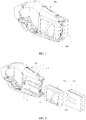
FIG. 1 is an overall view of mounted batteries mounted in place according to an example embodiment. -
FIG. 2 is a 3-dimentional view of a battery housing apparatus and batteries according to the first embodiment. -
FIG. 3 is an exploded view of a battery housing apparatus according to the first embodiment. -
FIG. 4 is a cross-sectional view of a battery housing apparatus according to the first embodiment. -
FIG. 5 is an exploded view of an indication assembly according to the first embodiment. -
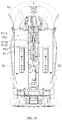
FIG. 6 is a top view of an indication assembly according to the first embodiment. -
FIG. 7A is a cross-sectional view of an indication assembly in a first operation state along AA' line inFIG. 6 according to the first embodiment. -
FIG. 7B is a cross-sectional view of an indication assembly in a second operation state along AA' line inFIG. 6 according to the first embodiment. -
FIG. 8 is an overall view of a battery housing apparatus according to the second embodiment. -
FIG. 9 is an exploded view of a battery housing apparatus according to the second embodiment. -
FIG. 10 is a cross-sectional view of a battery housing apparatus according to the second embodiment. -
FIG. 11 is an exploded view of an indication assembly according to the second embodiment. -
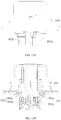
FIG. 12A is a side view of an indication assembly according to the second embodiment. -
FIG. 12B is a cross-sectional view of an indication assembly according to the second embodiment. - The present invention provides a battery housing apparatus that indicates whether batteries are mounted in place through a battery locking mechanism, facilitates service personnel to conveniently mount the batteries, and increases chances that the batteries are mounted in place. At the same time, batteries mounted in place are locked to prevent the batteries from loosening or falling off. The battery housing apparatus is suitable for unmanned aerial vehicles.
- Various embodiments of the present invention will be described below in detail.
- Referring to
FIGS. 1-7 , the present invention provides abattery housing apparatus 100. Thebattery housing apparatus 100 includes ahousing body 1 and abattery locking mechanism 2. Thebattery locking mechanism 2 is disposed on thehousing body 1. Thehousing body 1 includes at least onebattery compartment housing batteries 200. Thebattery locking mechanism 2 is used to indicate whether thebatteries 200 are mounted in place during a process of mounting thebatteries 200 in thecompartments housing body 1. After thebatteries 200 are mounted in place (shown inFIG. 1 ), thebatteries 200 are locked in the battery compartments. Anelectricity capacity indicator 13 is disposed on top of thehousing body 1. In some embodiments, theelectricity capacity indicator 13 includes four LED indicators. - Specifically, as shown in
FIG. 3 , thebattery locking mechanism 2 includes lockingassemblies indicator assembly 23. Theindicator assembly 23 is disposed on thehousing body 1, and cooperatively couples with thelocking assemblies locking assemblies indicator assembly 23 cooperatively couples with the lockingassembly 21, theindicator assembly 23 is capable of indicating whether the batteries are mounted in place under a control of the lockingassembly 21. - Referring further to
FIG. 3 andFIG. 4 , the lockingassembly 21 includes a lockingslider 211 and aslider spring 212. In the process of mounting the batteries in the battery compartments, the batteries overcome an elastic force of theslider spring 212 to dislocate the lockingslider 211. After the batteries are mounted in place, the lockingslider 211 is restored by the elastic force of theslider spring 212 to lock the batteries in the battery compartments 11, 12. - As shown in
FIGS. 2-7 , theindicator assembly 23 includes a key assembly, such as a firstkey assembly 231 and/or a secondkey assembly 232. The key assembly cooperatively couples with the lockingassembly 21, and indicates whether the battery is mounted in place under the control of the lockingassembly 21. Further, in the present invention, theindicator assembly 23 determines whether the battery is successfully mounted in place by checking a height of the battery relative to thehousing body 1. It is intuitive and convenient for battery mounting and dismounting. Specifically, when the lockingassembly 21 is dislocated and restored, the key assembly is placed at different heights relative to thehousing body 1. In addition, the key assembly controls the lockingassembly 21 to unlock the battery, such that the battery can be removed from the battery compartment. Further, in the present invention, theindicator assembly 23 includes anindicator bracket 234. Theindicator bracket 234 is fixed to thehousing body 1. The key assembly is disposed and enclosed in theindicator bracket 234. Theindicator bracket 234 is fixedly connected to thehousing body 1 by screws. Of course, theindicator assembly 234 may be connected to thehousing body 1 in other manners, such as snapping, which is not limited herein. - Further, for the
indicator assembly 23 to cooperatively couple with thelocking assemblies FIGS. 2-7 , theindicator assembly 23 includes a key spring, such as a firstkey spring 235b and/or a secondkey spring 236b. When the lockingassembly 21 is dislocated by the battery, the key assembly is restored by an elastic force of the key spring. When the lockingassembly 21 is restored, the lockingassembly 21 overcomes the elastic force of the key spring to dislocate the key assembly, such that the key assembly is placed at a different height relative tohousing body 1. - The battery housing apparatus of the first embodiment will be described below in detail.
- Referring to
FIGS. 2-7 , the first embodiment of the present invention provides a battery housing apparatus. Thebattery housing apparatus 100 includes ahousing body 1 and abattery locking mechanism 2. Thehousing body 1 includes afirst battery compartment 11 and asecond battery compartment 12 to housebatteries 200. Thebattery locking mechanism 2 is disposed on thehousing body 1. Thebattery locking mechanism 2 is used to indicate whether thebattery 200 is mounted in place during a process of mounting thebattery 200 in thefirst battery compartment 11 or thesecond battery compartment 12 of thehousing body 1, and to lock thebattery 200 in thefirst battery compartment 11 or thesecond battery compartment 12 after thebattery 200 is mounted in place. - Specifically, as shown in
FIG. 2 ,FIG. 3 , andFIG. 4 , thebattery locking mechanism 2 includes afirst locking assembly 21, asecond locking assembly 22, and anindicator assembly 23. Theindicator assembly 23 is disposed on thehousing body 1, and cooperatively couples with thefirst locking assembly 21 and thesecond locking assembly 22, respectively. Thefirst locking assembly 21 is dislocated by thebattery 200 in the process of mounting thebattery 200 in thefirst battery compartment 11, and is restored to lock thebattery 200 in thefirst battery compartment 11 after thebattery 200 is mounted in place. Because theindicator assembly 23 cooperatively couples with thefirst locking assembly 21, theindicator assembly 23 is capable of indicating whether thebattery 200 is mounted in place under a control of thefirst locking assembly 21. Similarly, thesecond locking assembly 22 is dislocated by thebattery 200 in the process of mounting thebattery 200 in thesecond battery compartment 12, and is restored to lock thebattery 200 in thesecond battery compartment 12 after thebattery 200 is mounted in place. Because theindicator assembly 23 cooperatively couples with thesecond locking assembly 22, theindicator assembly 23 is capable of indicating whether thebattery 200 is mounted in place under a control of thesecond locking assembly 22. It should be noted that, in other embodiments, thebattery housing apparatus 100 only houses onebattery 200. At this time, thebattery locking mechanism 2 includes only thefirst locking assembly 21 or thesecond locking assembly 22, which is dislocated by thebattery 200 in the process of mounting thebattery 200 in thefirst battery compartment 11 or thesecond battery compartment 12, and is restored to lock thebattery 200 in thefirst battery compartment 11 or thesecond battery compartment 12 after thebattery 200 is mounted in place. - As shown in
FIG. 3 andFIG. 4 , thefirst locking assembly 21 includes a lockingslider 211, aslider spring 212, and aslider bracket 213. Theslider bracket 213 is fixed in thefirst battery compartment 11. The lockingslider 211 is supported on theslider bracket 213 by an elastic force of theslider spring 212. In the process of mounting thebattery 200 in thefirst battery compartment 11, thebattery 200 overcomes the elastic force of theslider spring 212 to dislocate the lockingslider 211. After thebattery 200 is mounted in place, the lockingslider 211 is restored by the elastic force of theslider spring 212 to lock thebattery 200 in thefirst battery compartment 11. - Further, the
first locking assembly 21 includes aslider blocker 214. Theslider blocker 214 is fixedly connected to theslider bracket 213. The lockingslider 211 is disposed between theslider blocker 214 and theslider bracket 213, such that the lockingslider 211 is confined to move in a dislocation direction. - The
slider bracket 213 is fixed in thefirst battery compartment 11. For example, in some embodiments as illustrated in the drawings, theslider bracket 213 is fixed to the bottom of thebattery compartment 11. Theslider bracket 213 includes afirst guide slot 2131 coupled to afirst guide rail 201 on thebattery 200 extending in a direction of inserting thebattery 200 and a firstopen slot 2132 connecting to thefirst guide slot 2131. In some embodiments as illustrated in the drawings, to mount thebattery 200 more securely in thebattery housing apparatus 100, theslider bracket 213 is configured with twofirst guide slots 2131 in parallel with each other. One of the twofirst guide slots 2131 is connected to the firstopen slot 2132. Correspondingly, thebattery 200 is configured with twofirst guide rails 201 in parallel with each other. Of course, in other embodiments, theslider bracket 213 may be configured with three or morefirst guide slots 2131 in parallel with each other. - As shown in
FIG. 2 andFIG. 3 , the lockingslider 211 is disposed on a side of theslider bracket 213 facing away from thebattery 200, and is partially exposed in thefirst guide slot 2131 through the firstopen slot 2132. When thebattery 200 is being mounted in thefirst battery compartment 11, thefirst guide rails 201 insert into thefirst guide slots 2131 and dislocate the lockingslider 211. Specifically, a locking portion 2111 is disposed on a side of the lockingslider 211 adjacent to theslider bracket 213. The locking portion 2111 is exposed in thefirst guide slot 2131 through the firstopen slot 2132. Further, a second open slot 2112 and a first fixingpost 2113 adjacent to the second open slot 2112 are disposed on the lockingslider 211. As shown inFIG. 4 , anextension portion 2133 is disposed on a side of theslider bracket 213 adjacent to the lockingslider 211. Theextension portion 2133 inserts into the second open slot 2112. Asecond fixing post 2134 is disposed on theextension portion 2133 and extends toward the first fixingpost 2113. Two ends of theslider spring 212 are configured to sleeve on the first fixingpost 2113 and thesecond fixing post 2132, respectively, such that the lockingslider 211 is elastically supported on theslider bracket 213. - The dislocation direction of the locking
slider 211 is perpendicular to the direction of the battery insertion. As shown inFIG. 3 , the locking portion 2111 includes aguide surface 2111a disposed on a side of the locking portion 2111 facing toward the direction of the battery insertion to guide thefirst guide rail 201, and a locking surface 2111b disposed on a side of the locking portion 2111 facing away from the direction of the battery insertion to lock thefirst guide rail 201. After thebattery 200 is mounted in place, the locking portion 2111 locks thebattery 200 in the direction of the battery insertion. - As shown in
FIG. 2 andFIG. 3 , thefirst battery compartment 11 includes asecond guide rail 111 disposed on a side wall and extending in the direction of the battery insertion. That is, thesecond guide rail 111 is disposed on thehousing body 1. Correspondingly, thebattery 200 includes asecond guide slot 202. Thesecond guide rail 111 couples with thesecond guide slot 202 on thebattery 200 to lock thebattery 200 in a direction vertical to the bottom of thefirst battery compartment 11. Of course, in other embodiments, thefirst battery compartment 11 includes a second guide slot disposed on the side wall and extending in the direction of the battery insertion. Correspondingly, thebattery 200 includes a second guide rail. The second guide slot disposed on thehousing body 1 couples with the second guide rail disposed on thebattery 200 to lock thebattery 200 in the vertical direction. - In some embodiments as illustrated in the drawings, the
first battery compartment 11 and thesecond battery compartment 12 are disposed on two opposite sides of thehousing body 1, respectively. Thefirst locking assembly 21 corresponds to thefirst battery compartment 11 and thesecond locking assembly 22 corresponds to thesecond battery compartment 12. Thesecond locking assembly 22 is the same as thefirst locking assembly 21 and thesecond battery compartment 12 is the same as thefirst battery compartment 11. Thus, the detailed technical characteristics of thesecond locking assembly 22 and thesecond battery compartment 12 can be referred to the description of thefirst locking assembly 21 and thefirst battery compartment 11, respectively, and will not be repeated herein. - As shown in
FIG. 2 ,FIG. 4 ,FIG. 5 , andFIG. 7 , theindicator assembly 23 includes a firstkey assembly 231 and a secondkey assembly 232 mutually enclosed with each other. The firstkey assembly 231 cooperatively couples with thefirst locking assembly 21 and the secondkey assembly 232 cooperatively couples with thesecond locking assembly 22, such that the firstkey assembly 231 indicates whether thebattery 200 is mounted in place in thefirst battery compartment 11 under a control of thefirst locking assembly 21 and the secondkey assembly 232 indicates whether thebattery 200 is mounted in place in thesecond battery compartment 12 under a control of thesecond locking assembly 22. Further, in some embodiments, when thefirst locking assembly 21 is dislocated and restored, the firstkey assembly 231 is placed at different heights relative to thehousing body 1. Similarly, when thesecond locking assembly 22 is dislocated and restored, the secondkey assembly 232 is placed at different heights relative to thehousing body 1. In addition, when thebattery 200 is taken out from thebattery housing apparatus 100, the firstkey assembly 231 controls thefirst locking assembly 21 to unlock thebattery 200 to allow thebattery 200 to be taken out from thefirst battery compartment 11. Similarly, the secondkey assembly 232 controls thesecond locking assembly 22 to unlock thebattery 200 to allow thebattery 200 to be taken out from thesecond battery compartment 12. It should be noted that, in other embodiments, thebattery housing apparatus 100 only houses onebattery 200. At this time, theindicator assembly 23 includes either the firstkey assembly 231 or the secondkey assembly 232, and indicates whether thebattery 200 is mounted in place in thefirst battery compartment 11 under the control of thefirst locking assembly 21 or in thesecond battery compartment 12 under the control of thesecond locking assembly 22. - Further, the
indicator assembly 23 includes anindicator bracket 234. Theindicator bracket 234 is fixed to thehousing body 1. Theindicator bracket 234, the secondkey assembly 232, and the firstkey assembly 231 are sequentially nested. In some embodiments as illustrated in the drawings, theindicator bracket 234 is fixedly connected to thehousing body 1 by screws. - As shown in
FIG. 5 andFIG. 7 , the firstkey assembly 231 includes a first key 231a and a firstkey lock 231b. The secondkey assembly 232 includes a second key 232a and a secondkey lock 232b. The firstkey lock 231b includes afirst cylinder 2311b and afirst extension 2312b disposed on an end of thefirst cylinder 2311b. The secondkey lock 232b includes asecond cylinder 2321b and asecond extension 2322b disposed on an end of thesecond cylinder 2321b. Theindicator bracket 234, thesecond cylinder 2321b, andfirst cylinder 2311b are mutually enclosed. The first key 231a is fixed to the other end of the first cylinder 2311a. The second key 232a is fixed to the other end of thesecond cylinder 2321b. The second key 232a is enclosed in the first key 231a. Thefirst extension 2312b and thesecond extension 2322b extend toward both sides of theindicator bracket 234, respectively. When thefirst locking assembly 21 and thesecond locking assembly 22 are restored, thefirst extension 2312b and thesecond extension 2322b contact with thefirst locking assembly 21 and thesecond locking assembly 22, respectively, as shown inFIG. 7A . Then, theindicator assembly 23 is in a first operation state. - In some embodiments as illustrated in the drawings, the
first cylinder 2311b connects to thefirst key 231a by screw threads. Thesecond cylinder 2321b is fixedly connected to thesecond key 232a by screwing ascrew 237 into one end of thesecond cylinder 2321b. Of course, in other embodiments, the coupling between thefirst cylinder 2311b and the first key 231a and the coupling between thesecond cylinder 2321b and the second key 232a may be implemented in other manners, such as being bonded by an adhesive substance. - To prevent the
first cylinder 2311b from rotating relative to theindicator bracket 234 or thesecond cylinder 2321b from rotating relative to thefirst cylinder 2311b, a rotation-limiting mechanism is configured between theindicator bracket 234 and the firstkey assembly 231 or between the firstkey assembly 231 and the secondkey assembly 232. Further, theindicator assembly 23 includes at least one limiting key (2331 or 2332 as shown inFIG. 5 ). The at least one limiting key (2331 or 2332 as shown inFIG. 5 ) is configured between theindicator bracket 234 and thefirst cylinder 2311b or between thefirst cylinder 2311b and thesecond cylinder 2321b to prevent thefirst cylinder 2311b from rotating relative to theindicator bracket 234 or thesecond cylinder 2321b from rotating relative to thefirst cylinder 2311b. Specifically, as shown inFIG. 4 andFIG. 5 , the at least one limiting key includes a first limiting key 2331 and a second limiting key 2332. The first limiting key 2331 is disposed between theindicator bracket 234 and thefirst cylinder 2311b to prevent thefirst cylinder 2311b from rotating relative to theindicator bracket 234. The second limiting key 2332 is disposed between thefirst cylinder 2311b and thesecond cylinder 2321b to prevent the second cylinder 2321 from rotating relative to thefirst cylinder 2311b. - As shown in
FIG. 7 , afirst receiving hole 2341 and asecond receiving hole 2342 are disposed on theindicator bracket 234. In some embodiments, thefirst receiving hole 2341 and thesecond receiving hole 2342 are disposed on opposite sides. - Further, as shown in
FIG. 5 andFIG. 7 , theindicator assembly 23 includes a first threadedstud 235a, a firstkey spring 235b, afirst lock pin 235c, a second threadedstud 236a, a secondkey spring 236b, and asecond lock pin 236c. Thefirst lock pin 235c and the firstkey spring 235b are locked in thefirst receiving hole 2341 by the first threadedstud 235a, such that thefirst lock pin 235c elastically acts on thefirst extension 2312b. After thefirst locking assembly 21 is dislocated, thefirst lock pin 235c drives the firstkey assembly 231 to restore (the first operating state as shown inFIG. 7A ). After thefirst locking assembly 21 is restored, thefirst locking assembly 21 overcomes an elastic force of the firstkey spring 235b to dislocate the first key assembly 231 (a second operating state as shown inFIG. 7B ). It should be noted that, in some embodiments, to overcome the elastic force of the firstkey spring 235b by thefirst locking assembly 21 to dislocate the firstkey assembly 231 more effectively, the lockingslider 211 of thefirst locking assembly 21 has a flat surface on a side adjacent to the firstkey assembly 231. Similarly, the locking slider 221 of thesecond locking assembly 22 has a flat surface on a side adjacent to the secondkey assembly 232. - Similarly, the
second lock pin 236c and the secondkey spring 236b are locked in thesecond receiving hole 2342 by the second threadedstud 236a, such thatsecond lock pin 236c elastically acts on thesecond extension 2322b. After thesecond locking assembly 22 is dislocated, thesecond lock pin 236c drives the secondkey assembly 232 to restore (the first operating state as shown inFIG. 7A ). After thesecond locking assembly 22 is restored, thesecond locking assembly 22 overcomes an elastic force of the secondkey spring 236b to dislocate the second key assembly 232 (the second operating state as shown inFIG. 7B ). - The operation principle of the battery housing apparatus in some embodiments will be described below.
- During the process of mounting the
battery 200 in thefirst battery compartment 11 of thebattery housing apparatus 100, thebattery 200 overcomes the elastic force of theslider spring 212 in thefirst locking assembly 21 to dislocate the locking portion 2111 of the lockingslider 211. In the process, theindicator assembly 23 is in the first operating state. Thefirst lock pin 235c in theindicator assembly 23 drives the firstkey assembly 231 to restore, such that the firstkey assembly 231 is placed at a different height relative to thehousing body 1. That is, the first key 231a is placed at a different height relative to thehousing body 1. After thebattery 200 is mounted in place (as show inFIG. 1 ), the locking portion 2111 of the lockingslider 211 is restored by the elastic force of theslider spring 212. Then, a locking surface 2111b of the locking portion 2111 of the lockingslider 211 tightly contacts with thebattery 200 to lock thebattery 200 in the direction of the battery insertion. Theindicator assembly 23 is in the second operating state. The lockingslider 211 of thefirst locking assembly 21 overcomes the elastic force of the firstkey spring 235b of theindicator assembly 23 to dislocate the firstkey assembly 231. That is, the first key 231a is dislocated. Then, the first key 231a is dislocated to reach a same height as an external surface of thehousing body 1, thereby indicating that the battery is mounted in place (as shown inFIG. 1 ). - When the
battery 200 is taken out of thefirst battery compartment 11, the first key 231a of the firstkey assembly 231 is pressed. Then, the firstkey assembly 231 controls the lockingslider 211 of thefirst locking assembly 21 to dislocate to unlock thebattery 200, such that thebattery 200 can be taken out of thefirst battery compartment 11. - Similarly, the battery is mounted in place in the
second battery compartment 12 and the battery is taken out of thesecond battery compartment 12. The specific process is not described in detail. - Referring to
FIG. 8 , the present invention provides anotherbattery housing apparatus 800. Thebattery housing apparatus 800 includes ahousing body 8 and abattery locking mechanism 9. Thebattery locking mechanism 9 is disposed on thehousing body 8. Thehousing body 8 includes at least onebattery compartment battery 200. Thebattery locking mechanism 9 is used to indicate whether thebattery 200 is mounted in place during a process of mounting thebattery 200 in the battery compartment of thehousing body 8, and locks thebattery 200 in the battery compartment after thebattery 200 is mounted in place. Anelectricity capacity indicator 83 is disposed on top of thehousing body 8. In some embodiments, theelectricity capacity indicator 83 includes four LED indicators. - Specifically, as shown in
FIG. 9 , thebattery locking mechanism 9 includes lockingassemblies indicator assembly 93. Theindicator assembly 93 is disposed on thehousing body 8. Theindicator assembly 93 cooperatively couples with thelocking assemblies locking assemblies locking assemblies indicator assembly 93 cooperatively couples with thelocking assemblies indicator assembly 93 indicates whether the batteries are mounted in place under controls of thelocking assemblies - As shown in
FIG. 9 andFIG. 10 , the locking assembly includes a lockingslider 911 and aslider spring 912. In the process of mounting the battery in the battery compartment, the battery overcomes an elastic force of theslider spring 912 to dislocate the lockingslider 911. After the battery is mounted in place, the lockingslider 911 is restored by the elastic force of theslider spring 912 to lock the battery in thebattery compartment - As shown in
FIGS. 8-12 , theindicator assembly 93 includes a key assembly, such as a firstkey assembly 931 and/or a secondkey assembly 932. The key assembly cooperatively couples with the lockingassembly assembly indicator assembly 93 determines whether the battery is mounted in place by checking a height of the battery relative to thehousing body 8. It is intuitive and convenient for battery mounting and dismounting. Specifically, after the lockingassembly housing body 8. In addition, the key assembly controls the lockingassembly indicator assembly 93 includes anindicator bracket 934. Theindicator bracket 934 is fixedly connected to thehousing body 8. The key assembly is disposed and enclosed in theindicator bracket 934. Theindicator bracket 934 is fixed to thehousing body 8 by screws. Of course, theindicator bracket 934 may be fixed to thehousing body 8 in other manners, such as snapping, which will not be limited herein. - Further, for the indicator assembly to cooperatively couples with the locking assembly, as shown in
FIGS. 8-12 , the key assembly is connected to the lockingassembly assembly assembly - Referring to
FIGS. 8-12 , the present invention provides another battery housing apparatus. Compared to the first embodiment, the differences include the cooperatively coupling methods between the firstkey assembly 931 and thefirst locking assembly 91, between the secondkey assembly 932 and thesecond locking assembly 92, and between the firstkey assembly 931 and the secondkey assembly 932. The specifics are described below. - The first
key assembly 931 is connected to thefirst locking assembly 91. After thefirst locking assembly 931 is dislocated and restored, thefirst locking assembly 91 drives the firstkey assembly 931 to different heights relative to thehousing body 8. The secondkey assembly 932 is connected to thesecond locking assembly 92. After thesecond locking assembly 932 is dislocated and restored, thesecond locking assembly 92 drives the secondkey assembly 932 to different heights relative to thehousing body 8. - In addition, as shown in
FIG. 11 , the firstkey assembly 931 includes a first key 931a and a firstkey lock 931b. The secondkey assembly 932 includes a second key 932a and a secondkey lock 932b. In some embodiments, the first key 931a includes afirst cylinder 9311a and afirst fixing portion 9312a disposed on one end of thefirst cylinder 9311a. The second key 932a includes asecond cylinder 9321a and asecond fixing portion 9322a disposed on one end of thesecond cylinder 9321a. Theindicator bracket 934, thefirst cylinder 9311a, and thesecond cylinder 9321a are enclosed with each other. The firstkey lock 931b is connected between thefirst fixing portion 9312a and thefirst locking assembly 91. After thefirst locking assembly 91 is dislocated and restored, thefirst locking assembly 91 drives the firstkey assembly 931 to different heights relative to thehousing body 8. The secondkey lock 932b is connected between thesecond fixing portion 9322a and thesecond locking assembly 92. After thesecond locking assembly 92 is dislocated and restored, thesecond locking assembly 92 drives the secondkey assembly 932 to different heights relative to thehousing body 8. - As shown in
FIG. 10 andFIG. 11 , the firstkey lock 931b and the secondkey lock 932b are fixedly connected to thefirst fixing 9312a and thesecond fixing portion 9322a byscrews 935, respectively. In other embodiments, the firstkey lock 931b and thefirst fastening portion 9312a may be fixedly connected in other manners, for example, being bonded by an adhesive substance, which will not be limited herein. - As shown in
FIG. 9 andFIG. 10 , the firstkey lock 931b and the secondkey lock 932b are snapped to thefirst locking assembly 91 and thesecond locking assembly 92, respectively. In some embodiments, a snappingportion 9114 is disposed on a side of the lockingslider 911 of thefirst locking assembly 91 adjacent to the firstkey lock 931b. The snappingportion 9114 is connected to the firstkey lock 931b and the secondkey lock 932b, respectively. Similarly, a snapping portion is disposed on a side of the locking slider 921 of thesecond locking assembly 92 adjacent to the secondkey lock 932b. Of course, in other embodiments, the firstkey lock 931b and the secondkey lock 932b may be connected to thefirst locking assembly 91 and thesecond locking assembly 92 in other manners, respectively, for example, being bonded by an adhesive substance, which will not be limited herein. - As shown in
FIG. 11 ,gaskets 933 are disposed between both the firstkey lock 931b and the secondkey lock 932b and theindicator bracket 934. When the first key 931a or the second key 932a pops up, thegasket 933 reduces an impact by the first key 931a or the second key 932a to protect the first key 931a or the second key 932a and reduces noise at the same time. In some embodiments, thegaskets 933 can be made of rubber, or other elastic material, such as a thermoplastic elastomer. - The
indicator bracket 934 couples with thefirst cylinder 9311 a by a D-shaped cross-section in a direction vertical to an axis direction to prevent thefirst cylinder 9311a from rotating relative to theindicator bracket 934. As shown inFIG. 11 , a D-shapedportion 9313a is disposed on a side of thefirst cylinder 9311a. Because thefirst cylinder 9311a is enclosed in theindicator bracket 934, correspondingly, another D-shaped portion (not shown) is disposed in theindicator bracket 934 matching the D-shapedportion 9313a, such that theindicator bracket 934 couples with thefirst cylinder 9311a by a D-shaped cross-section in a direction vertical to the axis direction. - As shown in
FIG. 11 , at least one rotation-limitingrib 936 is configured on the firstkey lock 931a and the secondkey lock 932a. In some embodiments, three rotation-limitingribs 936 are configured on both the firstkey lock 931a and the secondkey lock 932a. At least one rotation-limitingrib 936 on the firstkey lock 931a misaligns with at least one rotation-limitingrib 936 on the secondkey lock 932a to prevent thesecond cylinder 9321a from rotating relative to thefirst cylinder 9311 a. - The operation principle of the battery housing apparatus of some embodiments will be described below.
- In the process of mounting the
battery 200 in thefirst battery compartment 81 of thebattery housing apparatus 800, thebattery 200 overcomes the elastic force of theslider spring 912 in thefirst locking assembly 91 to dislocate thelocking portion 9111 of the lockingslider 911. In the process, because thefirst locking assembly 91 is connected to firstkey assembly 931 of theindicator assembly 93, thefirst locking assembly 91 drives the firstkey assembly 931 to different heights relative to thehousing body 8. That is, the first key 931a is placed at different heights relative to thehousing body 8. After thebattery 200 is mounted in place (as shown inFIG. 1 ), the lockingportion 9111 of the lockingslider 911 is restored by the elastic force of theslider spring 912. Then, alocking surface 9111b of the lockingportion 9111 of the lockingslider 911 tightly contacts with thebattery 200 to lock thebattery 200 in the direction of the battery insertion. Because thefirst locking assembly 91 is connected to the firstkey assembly 931 of theindicator assembly 93, thefirst locking assembly 91 drives the firstkey assembly 931 to different heights relative to thehousing body 8. The first key 931a is dislocated to reach a same height as an external surface of thehousing body 8, thereby indicating that thebattery 200 is mounted in place. - When the
battery 200 is taken out of thefirst battery compartment 81, the first key 931a of the firstkey assembly 931 is pressed. Then, the firstkey assembly 931 controls the lockingslider 911 of thefirst locking assembly 91 to dislocate to unlock the battery 200., such that thebattery 200 can be taken out of thefirst battery compartment 81. - Similarly, the battery is mounted in place in the second battery compartment and the battery is taken out of the second battery compartment. The specific process is not described in detail.
- It should be noted that the shapes of the housing bodies in the two embodiments may be the same or different, which will not be limited herein.
- The present invention also provides an unmanned aerial vehicle. The unmanned vehicle includes the battery housing apparatus in the embodiments described above.
- It will be appreciated that the described embodiments are some rather than all of the embodiments of the present invention. Other embodiments of the invention will be apparent to those skilled in the art from consideration of the specification and practice of the embodiments disclosed herein. It is intended that the specification and examples be considered as example only and not to limit the scope of the invention, with a true scope and spirit of the invention being indicated by the following claims.
Claims (30)
- A battery housing apparatus, comprising:
a housing body and a battery locking mechanism, wherein:the housing body is configured with at least one battery compartment for housing a battery; andthe battery locking mechanism is disposed on the housing body and configured to indicate whether the battery is mounted in place during a process of mounting the battery in the battery compartment and to lock the battery in the battery compartment after the battery is mounted in place. - The apparatus of claim 1, wherein the battery locking mechanism includes:
a locking assembly and an indicator assembly, wherein:the locking assembly is configured to be dislocated by the battery in the process of mounting the battery in the battery compartment and to be restored to lock the battery in the battery compartment after the battery is mounted in place; andthe indicator assembly is disposed on the housing body and configured to be operatively coupled with the locking assembly to indicate whether the battery is mounted in place under a control of the locking assembly. - The apparatus of claim 2, wherein:the locking assembly includes a locking slider and a slider spring;in the process of mounting the battery in the battery compartment, the battery overcomes an elastic force of the slider spring to dislocate the locking slider; andafter the battery is mounted in place, the locking slider is restored by the elastic force of the slider spring to lock the battery in the battery compartment.
- The apparatus of claim 3, wherein:the locking assembly further includes a slider bracket;the slider bracket is fixed in the battery compartment; andthe locking slider is supported on the slider bracket by the elastic force of the slider spring.
- The apparatus of claim 4, wherein:the slider bracket is fixed to a bottom of the battery compartment;a first guide slot coupling with a first guide rail on the battery and a first open slot connected to the first guide slot are disposed on the slider bracket and extend in a direction of inserting the battery;the locking slider is disposed on a side of the slider bracket facing away from the battery, and is partially exposed in the first guide slot through the first open slot; andthe first guide rail inserts into the first guide slot to dislocate the locking slider during the process of mounting the battery in the battery compartment.
- The apparatus of claim 5, wherein:a locking portion is configured on a side of the locking slider adjacent to the slider bracket;the locking portion is exposed in the first guide slot through the first open slot;a second open slot and a first fixing post adjacent to the second open slot are configured on the locking slider;an extension portion is configured on a side of the slider bracket adjacent to the locking slider;the extension portion inserts into the second open slot;a second fixing post is configured on the extension portion to extend toward the first fixing post; andtwo ends of the slider spring are configured to sleeve on the first fixing post and the second fixing post, respectively, such that the locking slider is elastically supported on the slider bracket.
- The apparatus of claim 6, wherein:the dislocation direction is perpendicular to the direction of the battery insertion;the locking portion includes a guide surface disposed on a side of the locking portion facing toward the direction of the battery insertion to guide the first guide rail, and a locking surface disposed on a side of the locking portion facing away from the direction of the battery insertion to lock the first guide rail; andwhen the battery is mounted in place, the locking portion locks the battery in the direction of the battery insertion.
- The apparatus of claim 5, wherein:a second guide rail or a second guide slot is configured on a side wall of the battery compartment to extend in the direction of the battery insertion; andthe second guide rail or the second guide slot configured on the housing body is used to couple with a second guide slot or a second guide rail on the battery to lock the battery in a direction perpendicular to the bottom of the battery compartment.
- The apparatus of claim 4, wherein:the locking assembly further includes a slider blocker;the slider blocker is fixed to the slider bracket; andthe locking slider is disposed between the slider blocker and the slider bracket to confine the locking slider to move in the dislocation direction.
- The apparatus of claim 2, wherein:the indicator assembly includes a key assembly; andthe key assembly cooperatively couples with the locking assembly to indicate whether the battery is mounted in place under the control of the locking assembly.
- The apparatus of claim 10, wherein:
the key assembly further controls the locking assembly to unlock the battery to allow the battery to be taken out of the battery compartment. - The apparatus of claim 10, wherein:
when the locking assembly is dislocated or restored, the key assembly is placed at different heights relative to the housing body. - The apparatus of claim 12, wherein:the indicator assembly further includes a key spring;when the locking assembly is dislocated by the battery, the key assembly is restored by an elastic force of the key spring; andwhen the locking assembly is restored, the locking assembly overcomes the elastic force of the key spring to dislocate the key assembly, such that the key assembly is placed at a different height relative to the housing body.
- The apparatus of claim 12, wherein:the key assembly connects with the locking assembly; andwhen the locking assembly is dislocated or restored, the locking assembly drives the key assembly to different heights relative to the housing body.
- The apparatus of claim 10, wherein:the indicator assembly further includes an indicator bracket;the indicator bracket is fixed to the housing body; andthe key assembly is enclosed in the indicator bracket.
- The apparatus of claim 10, wherein:the housing body includes a first battery compartment and a second battery compartment disposed on two opposite sides;the locking assembly includes a first locking assembly corresponding to the first battery compartment and a second locking assembly corresponding to the second battery compartment;the indicator assembly includes a first key assembly and a second key assembly enclosing with each other;the first key assembly cooperatively couples with the first locking assembly to indicate whether the battery is mounted in place in the first battery compartment under a control of the first locking assembly; andthe second key assembly cooperatively couples with the second locking assembly to indicate whether the battery is mounted in place in the second battery compartment under a control of the second locking assembly.
- The apparatus of claim 16, wherein:the indicator assembly further includes an indicator bracket;the indicator bracket is fixed to the housing body; andthe indicator bracket, the first key assembly, and the second key assembly are sequentially nested.
- The apparatus of claim 17, wherein:
a rotation-limiting mechanism is configured between the indicator bracket and the first key assembly or between the first key assembly and the second key assembly. - The apparatus of claim 17, wherein:the first key assembly includes a first key and a first key lock;the second key assembly includes a second key and a second key lock;the first key lock includes a first cylinder and a first extension disposed on an end of the first cylinder;the second key lock includes a second cylinder and a second extension disposed on an end of the second cylinder;the indicator bracket, the first cylinder, and the second cylinder are enclosed with each other;the first key is fixed to the other end of the first cylinder;the second key is fixed to the other end of the second cylinder;the second key is enclosed in the first key; andthe first extension and the second extension extend toward two opposite sides of the indicator bracket, and contact with the first locking assembly and the second locking assembly respectively when the first locking assembly and the second locking assembly are restored.
- The apparatus of claim 19, wherein:the first cylinder connects to the first key by screw threads; andthe second cylinder fixedly connects to the second key by a screw inserted into one end of the second cylinder.
- The apparatus of claim 19, wherein:the indicator assembly further includes at least one limiting key; andthe at least one limiting key is configured between the indicator bracket and the first cylinder or between the first cylinder and the second cylinder to prevent the first cylinder from rotating relative to the indicator bracket or the second cylinder from rotating relative to the first cylinder.
- The apparatus of claim 21, wherein:the at least one limiting key includes a first limiting key and a second limiting key;the first limiting key is disposed between the indicator bracket and the first cylinder to prevent the first cylinder from rotating relative to the indicator bracket; andthe second limiting key is disposed between the first cylinder and the second cylinder to prevent the second cylinder from rotating relative to the first cylinder.
- The apparatus of claim 19, wherein:a first receiving hole and a second receiving hole are configured on the indicator bracket;the indicator assembly further includes a first lock pin, a first key spring, a first threaded stud, a second lock pin, a second key spring, and a second threaded stud;the first lock pin and the first key spring are locked in the first receiving hole by the first threaded stud, such that the first lock pin elastically acts on the first extension;when the first locking assembly is dislocated, the first lock pin drives the first key assembly to restore;when the first locking assembly is restored, the first locking assembly overcomes an elastic force of the first key spring to dislocate the first key assembly;the second lock pin and the second key spring are locked in the second receiving hole by the second threaded stud, such that second lock pin elastically acts on the second extension;when the second locking assembly is dislocated, the second lock pin drives the second key assembly to restore; andwhen the second locking assembly is restored, the second locking assembly overcomes an elastic force of the second key spring to dislocate the second key assembly.
- The apparatus of claim 17, wherein:the first key assembly includes a first key and a first key lock;the second key assembly includes a second key and a second key lock;the first key includes a first cylinder and a first fixing portion disposed on one end of the first cylinder;the second key includes a second cylinder and a second fixing portion disposed on one end of the second cylinder;the indicator bracket, the first cylinder, and the second cylinder are enclosed with each other;the first key lock is connected between the first fixing portion and the first locking assembly;when the first locking assembly is dislocated and restored, the first locking assembly drives the first key assembly to different heights relative to the housing body;the second key lock is connected between the second fixing portion and the second locking assembly; andwhen the second locking assembly is dislocated and restored, the second locking assembly drives the second key assembly to different heights relative to the housing body.
- The apparatus of claim 24, wherein:
the first key lock and the second key lock are fixedly connected to the first fixing portion and the second fixing portion by screws, respectively. - The apparatus of claim 24, wherein:
the first key lock and the second key lock are snapped to the first locking assembly and the second locking assembly, respectively. - The apparatus of claim 24, wherein:
gaskets are configured between the first key lock and the indicator bracket and between the second key lock and the indicator bracket. - The apparatus of claim 24, wherein:
the indicator bracket couples with the first cylinder by a D-shaped cross-section in a direction vertical to an axis direction to prevent the first cylinder from rotating relative to the indicator bracket - The apparatus of claim 24, wherein:at least one rotation-limiting rib is configured on the first key lock and the second key, respectively; andthe at least one rotation-limiting rib on the first key lock misaligns with the at least one rotation-limiting rib on the second key lock to prevent the second cylinder from rotating relative to the first cylinder.
- An unmanned aerial vehicle, comprising a battery housing apparatus of any of claims 1-29.
Applications Claiming Priority (1)
| Application Number | Priority Date | Filing Date | Title |
|---|---|---|---|
| PCT/CN2016/104368 WO2018081957A1 (en) | 2016-11-02 | 2016-11-02 | Battery containing device and unmanned aerial vehicle |
Publications (2)
| Publication Number | Publication Date |
|---|---|
| EP3537499A1 true EP3537499A1 (en) | 2019-09-11 |
| EP3537499A4 EP3537499A4 (en) | 2019-12-04 |
Family
ID=59623880
Family Applications (1)
| Application Number | Title | Priority Date | Filing Date |
|---|---|---|---|
| EP16920892.3A Withdrawn EP3537499A4 (en) | 2016-11-02 | 2016-11-02 | CONTAINER DEVICE FOR BATTERY, BATTERY AND AERIAL VEHICLE WITHOUT PILOT |
Country Status (5)
| Country | Link |
|---|---|
| US (2) | US11088414B2 (en) |
| EP (1) | EP3537499A4 (en) |
| JP (1) | JP6853353B2 (en) |
| CN (2) | CN110021723B (en) |
| WO (1) | WO2018081957A1 (en) |
Families Citing this family (17)
| Publication number | Priority date | Publication date | Assignee | Title |
|---|---|---|---|---|
| CN107223108B (en) * | 2016-02-29 | 2019-09-27 | 深圳市大疆创新科技有限公司 | Power components, unmanned aerial vehicles and remote control mobile devices |
| EP3299291B1 (en) * | 2016-09-23 | 2020-04-08 | microdrones GmbH | Unmanned aircraft |
| WO2019140642A1 (en) * | 2018-01-19 | 2019-07-25 | 深圳市大疆创新科技有限公司 | Battery safety alert system |
| CN109353514B (en) * | 2018-11-20 | 2025-01-03 | 一飞智控(天津)科技有限公司 | Warehouse integrated logistics drone |
| CN109353513B (en) * | 2018-11-20 | 2025-03-04 | 一飞智控(天津)科技有限公司 | Integrated logistics drone |
| CN111356639A (en) * | 2019-03-19 | 2020-06-30 | 深圳市大疆创新科技有限公司 | Drones and Batteries |
| CN110299490B (en) * | 2019-07-01 | 2022-04-05 | 纳恩博(北京)科技有限公司 | Battery device of scooter and battery pack thereof |
| WO2021120073A1 (en) * | 2019-12-18 | 2021-06-24 | 深圳市大疆创新科技有限公司 | Switch structure, battery assembly, and electronic device |
| DE102020104783A1 (en) * | 2020-02-24 | 2021-08-26 | Volocopter Gmbh | Battery holding device, battery system, aircraft and method for changing a battery for an aircraft |
| CN112740468A (en) * | 2020-03-02 | 2021-04-30 | 深圳市大疆创新科技有限公司 | Locking Assembly and Removable Platform |
| JP7537984B2 (en) | 2020-10-19 | 2024-08-21 | Ihi運搬機械株式会社 | What is a drone port and how to use it? |
| TWI779431B (en) * | 2020-12-18 | 2022-10-01 | 東友科技股份有限公司 | Drone and battery exchange system thereof |
| DE102021105375A1 (en) | 2021-03-05 | 2022-09-08 | Volocopter Gmbh | Battery cooling device and method for cooling a battery cell of an electrically powered aircraft |
| DE102021105378A1 (en) | 2021-03-05 | 2022-09-08 | Volocopter Gmbh | Battery cooling method and cooling system |
| CN112918684B (en) * | 2021-03-17 | 2023-04-07 | 深圳市道通智能航空技术股份有限公司 | Unmanned aerial vehicle and control method thereof |
| CN113086218B (en) * | 2021-06-09 | 2021-08-13 | 南京信息工程大学 | A power supply device for an unmanned aerial vehicle for marine exploration |
| EP4556380A1 (en) * | 2023-11-17 | 2025-05-21 | "Rogoz" Spolka z Ograniczona Odpowiedzialnoscia- A-Spolka Komandytowo-Akcyjna | A frame for unmanned aerial vehicle and a method of replacing battery |
Family Cites Families (31)
| Publication number | Priority date | Publication date | Assignee | Title |
|---|---|---|---|---|
| JPH01227350A (en) * | 1988-03-08 | 1989-09-11 | Fuji Photo Film Co Ltd | Locking mechanism of battery |
| US5191855A (en) * | 1990-02-26 | 1993-03-09 | Pittway Corporation | Battery missing indicator |
| JP3256978B2 (en) * | 1991-04-24 | 2002-02-18 | 松下電器産業株式会社 | Battery locking device |
| JP3612801B2 (en) * | 1995-07-03 | 2005-01-19 | ソニー株式会社 | Electronics |
| KR200153281Y1 (en) * | 1996-10-04 | 1999-08-02 | 김영환 | Battery pack detaching apparatus of portable wireless phone |
| CN1229802C (en) * | 2002-06-14 | 2005-11-30 | 上海乐金广电电子有限公司 | Portable DVD player battery components fixing device |
| CN100420087C (en) * | 2003-06-23 | 2008-09-17 | 比亚迪股份有限公司 | Laminated lithium-ion secondary battery |
| KR100595625B1 (en) * | 2003-12-10 | 2006-06-30 | 엘지전자 주식회사 | Battery lock of portable terminal |
| TWI252015B (en) * | 2004-07-16 | 2006-03-21 | Benq Corp | Mobile phone and battery-fixing device |
| KR100664210B1 (en) * | 2005-09-01 | 2007-01-03 | 엘지전자 주식회사 | Battery separator of mobile communication terminal |
| JP2007157663A (en) * | 2005-12-08 | 2007-06-21 | Eastman Kodak Co | Battery storage device |
| JP4725317B2 (en) * | 2005-12-26 | 2011-07-13 | ソニー株式会社 | Electronics |
| CN101232083A (en) * | 2007-01-26 | 2008-07-30 | 深圳迈瑞生物医疗电子股份有限公司 | Battery disassembly structure |
| JP2009205980A (en) * | 2008-02-28 | 2009-09-10 | Sony Corp | Battery mounting device and portable electronic equipment |
| CN101626069B (en) * | 2008-07-11 | 2013-06-05 | 深圳富泰宏精密工业有限公司 | Battery cover snapclose structure |
| CN101728502B (en) * | 2008-10-31 | 2012-03-07 | 鸿富锦精密工业(深圳)有限公司 | Battery fixing device |
| CN201294234Y (en) * | 2008-11-07 | 2009-08-19 | 华晶科技股份有限公司 | Push-type battery exit structure |
| JP2011258444A (en) * | 2010-06-10 | 2011-12-22 | Sony Corp | Battery lock mechanism and electronic apparatus |
| CN201918754U (en) * | 2010-09-10 | 2011-08-03 | 庄森 | Parallel charging device for multiple power batteries |
| JP5748990B2 (en) * | 2010-11-30 | 2015-07-15 | 三洋電機株式会社 | Battery pack and electric vehicle equipped with the same |
| BR112013014098B1 (en) * | 2010-12-06 | 2020-10-27 | Omnicell, Inc | system and method for monitoring and controlling a medical storage unit |
| CN202196818U (en) * | 2011-07-21 | 2012-04-18 | 北京理工大学 | Drawer-type quick change battery box of electric sedan |
| CN102514471B (en) * | 2011-12-16 | 2014-04-02 | 奇瑞汽车股份有限公司 | Mounting structure of battery of electric vehicle |
| CN103187546B (en) * | 2011-12-30 | 2016-06-15 | 北京谊安医疗系统股份有限公司 | A kind of drawing box assembly for battery altering and the method changing battery |
| CN103617692A (en) * | 2013-11-13 | 2014-03-05 | 东南(福建)汽车工业有限公司 | Battery pack locking alarming device of quick-changing-type electric automobile |
| CN107742915B (en) * | 2013-12-06 | 2021-02-19 | 深圳市大疆创新科技有限公司 | Battery and aircraft with same |
| CN204223172U (en) * | 2014-10-27 | 2015-03-25 | 广州极飞电子科技有限公司 | Rotor craft battery fastening structure |
| CN205376593U (en) * | 2015-12-14 | 2016-07-06 | 深圳市道通智能航空技术有限公司 | Unmanned aerial vehicle battery and unmanned aerial vehicle |
| CN107438566B (en) * | 2016-10-27 | 2019-07-19 | 深圳市大疆创新科技有限公司 | Cell fixing device, battery and unmanned vehicle |
| CN206155799U (en) * | 2016-11-02 | 2017-05-10 | 深圳市大疆创新科技有限公司 | Battery storage device and unmanned aerial vehicle |
| CN206528646U (en) * | 2017-02-24 | 2017-09-29 | 深圳市大疆创新科技有限公司 | Battery compartment and unmanned vehicle |
-
2016
- 2016-11-02 EP EP16920892.3A patent/EP3537499A4/en not_active Withdrawn
- 2016-11-02 CN CN201910188771.0A patent/CN110021723B/en not_active Expired - Fee Related
- 2016-11-02 WO PCT/CN2016/104368 patent/WO2018081957A1/en not_active Ceased
- 2016-11-02 JP JP2019522311A patent/JP6853353B2/en not_active Expired - Fee Related
- 2016-11-02 CN CN201680002377.8A patent/CN107074372B/en active Active
-
2019
- 2019-04-29 US US16/397,555 patent/US11088414B2/en active Active
-
2021
- 2021-08-09 US US17/397,239 patent/US20210376414A1/en not_active Abandoned
Also Published As
| Publication number | Publication date |
|---|---|
| US11088414B2 (en) | 2021-08-10 |
| JP2019537822A (en) | 2019-12-26 |
| CN107074372A (en) | 2017-08-18 |
| CN110021723A (en) | 2019-07-16 |
| EP3537499A4 (en) | 2019-12-04 |
| US20210376414A1 (en) | 2021-12-02 |
| JP6853353B2 (en) | 2021-03-31 |
| CN110021723B (en) | 2022-06-14 |
| US20190259998A1 (en) | 2019-08-22 |
| CN107074372B (en) | 2019-03-29 |
| WO2018081957A1 (en) | 2018-05-11 |
Similar Documents
| Publication | Publication Date | Title |
|---|---|---|
| US11088414B2 (en) | Battery housing apparatus and unmanned aerial vehicle | |
| US8936124B2 (en) | Fastening device | |
| KR100889242B1 (en) | WMS with waterproof function | |
| EP3663142A1 (en) | Battery box, bracket and battery box assembly | |
| KR20170073468A (en) | Battery moduel, battery pack comprising the battery moduel and vehicle comprising the battery pack | |
| JP2013514939A (en) | Device for attaching batteries to the car chassis | |
| CN109421505A (en) | For storing the device of electric energy for motor vehicles | |
| CN103633490B (en) | The reliable plug-in connection of a kind of connector without latch assembly and assembly method thereof and docking calculation | |
| US20210157019A1 (en) | Removable battery connector adapter | |
| US10879507B2 (en) | Onboard battery | |
| US6926994B2 (en) | Device with detachable battery mounting | |
| CN205355323U (en) | Reliable connector | |
| CN219406935U (en) | Unmanned aerial vehicle nacelle joint formula quick detach structure | |
| CN216250206U (en) | Insulating sleeve made of thermoplastic material | |
| CN212161966U (en) | Bolt-sealed connector, mounting structure thereof and battery box | |
| CN212588430U (en) | Communication equipment | |
| CN209804954U (en) | Quick access device and emergency distribution box of generator car | |
| CN210779066U (en) | Energy storage connector | |
| CN221883963U (en) | Protective device for communication line connector | |
| CN217603711U (en) | Bracket structure and vehicle oil pump bracket assembly | |
| CN215184678U (en) | Connector with excellent anti-combustion performance | |
| CN223267059U (en) | Power distribution network inspection device | |
| CN219393940U (en) | Pre-fixed charging socket | |
| CN114142148B (en) | Automatic battery replacement structure | |
| CN215732318U (en) | Quick change device |
Legal Events
| Date | Code | Title | Description |
|---|---|---|---|
| STAA | Information on the status of an ep patent application or granted ep patent |
Free format text: STATUS: THE INTERNATIONAL PUBLICATION HAS BEEN MADE |
|
| PUAI | Public reference made under article 153(3) epc to a published international application that has entered the european phase |
Free format text: ORIGINAL CODE: 0009012 |
|
| STAA | Information on the status of an ep patent application or granted ep patent |
Free format text: STATUS: REQUEST FOR EXAMINATION WAS MADE |
|
| 17P | Request for examination filed |
Effective date: 20190222 |
|
| AK | Designated contracting states |
Kind code of ref document: A1 Designated state(s): AL AT BE BG CH CY CZ DE DK EE ES FI FR GB GR HR HU IE IS IT LI LT LU LV MC MK MT NL NO PL PT RO RS SE SI SK SM TR |
|
| AX | Request for extension of the european patent |
Extension state: BA ME |
|
| A4 | Supplementary search report drawn up and despatched |
Effective date: 20191104 |
|
| RIC1 | Information provided on ipc code assigned before grant |
Ipc: B64C 7/00 20060101ALI20191028BHEP Ipc: H01M 2/10 20060101AFI20191028BHEP |
|
| DAV | Request for validation of the european patent (deleted) | ||
| DAX | Request for extension of the european patent (deleted) | ||
| STAA | Information on the status of an ep patent application or granted ep patent |
Free format text: STATUS: EXAMINATION IS IN PROGRESS |
|
| 17Q | First examination report despatched |
Effective date: 20210204 |
|
| GRAP | Despatch of communication of intention to grant a patent |
Free format text: ORIGINAL CODE: EPIDOSNIGR1 |
|
| STAA | Information on the status of an ep patent application or granted ep patent |
Free format text: STATUS: GRANT OF PATENT IS INTENDED |
|
| RIC1 | Information provided on ipc code assigned before grant |
Ipc: H01M 50/20 20210101AFI20220311BHEP |
|
| INTG | Intention to grant announced |
Effective date: 20220420 |
|
| STAA | Information on the status of an ep patent application or granted ep patent |
Free format text: STATUS: THE APPLICATION IS DEEMED TO BE WITHDRAWN |
|
| 18D | Application deemed to be withdrawn |
Effective date: 20220831 |