EP3537375B1 - Bildsegmentierungsverfahren, bildsegmentierungssystem und vorrichtung damit, und speichermedium - Google Patents
Bildsegmentierungsverfahren, bildsegmentierungssystem und vorrichtung damit, und speichermedium Download PDFInfo
- Publication number
- EP3537375B1 EP3537375B1 EP17835447.8A EP17835447A EP3537375B1 EP 3537375 B1 EP3537375 B1 EP 3537375B1 EP 17835447 A EP17835447 A EP 17835447A EP 3537375 B1 EP3537375 B1 EP 3537375B1
- Authority
- EP
- European Patent Office
- Prior art keywords
- connected region
- positions
- target object
- image
- reference position
- Prior art date
- Legal status (The legal status is an assumption and is not a legal conclusion. Google has not performed a legal analysis and makes no representation as to the accuracy of the status listed.)
- Active
Links
- 238000003709 image segmentation Methods 0.000 title claims description 39
- 238000000034 method Methods 0.000 title claims description 37
- 230000011218 segmentation Effects 0.000 claims description 52
- 238000012847 principal component analysis method Methods 0.000 claims description 5
- 238000004590 computer program Methods 0.000 claims 4
- 210000000707 wrist Anatomy 0.000 description 16
- 238000012545 processing Methods 0.000 description 8
- 238000004364 calculation method Methods 0.000 description 7
- 238000004458 analytical method Methods 0.000 description 5
- 230000008569 process Effects 0.000 description 5
- 230000003993 interaction Effects 0.000 description 4
- 238000010586 diagram Methods 0.000 description 3
- 238000005516 engineering process Methods 0.000 description 3
- 238000011160 research Methods 0.000 description 3
- 230000008859 change Effects 0.000 description 2
- 238000000605 extraction Methods 0.000 description 2
- 210000000245 forearm Anatomy 0.000 description 2
- 230000006870 function Effects 0.000 description 2
- 238000004422 calculation algorithm Methods 0.000 description 1
- 230000001419 dependent effect Effects 0.000 description 1
- 238000001514 detection method Methods 0.000 description 1
- 238000011161 development Methods 0.000 description 1
- 230000018109 developmental process Effects 0.000 description 1
- 230000000694 effects Effects 0.000 description 1
- 238000010801 machine learning Methods 0.000 description 1
- 239000004065 semiconductor Substances 0.000 description 1
- 239000004984 smart glass Substances 0.000 description 1
- 238000007619 statistical method Methods 0.000 description 1
- 238000012360 testing method Methods 0.000 description 1
- 230000009466 transformation Effects 0.000 description 1
- 230000000007 visual effect Effects 0.000 description 1
Images


Classifications
-
- G—PHYSICS
- G06—COMPUTING; CALCULATING OR COUNTING
- G06V—IMAGE OR VIDEO RECOGNITION OR UNDERSTANDING
- G06V40/00—Recognition of biometric, human-related or animal-related patterns in image or video data
- G06V40/20—Movements or behaviour, e.g. gesture recognition
- G06V40/28—Recognition of hand or arm movements, e.g. recognition of deaf sign language
-
- G—PHYSICS
- G06—COMPUTING; CALCULATING OR COUNTING
- G06T—IMAGE DATA PROCESSING OR GENERATION, IN GENERAL
- G06T7/00—Image analysis
- G06T7/10—Segmentation; Edge detection
- G06T7/11—Region-based segmentation
-
- G—PHYSICS
- G06—COMPUTING; CALCULATING OR COUNTING
- G06T—IMAGE DATA PROCESSING OR GENERATION, IN GENERAL
- G06T7/00—Image analysis
- G06T7/10—Segmentation; Edge detection
- G06T7/155—Segmentation; Edge detection involving morphological operators
-
- G—PHYSICS
- G06—COMPUTING; CALCULATING OR COUNTING
- G06T—IMAGE DATA PROCESSING OR GENERATION, IN GENERAL
- G06T7/00—Image analysis
- G06T7/10—Segmentation; Edge detection
- G06T7/194—Segmentation; Edge detection involving foreground-background segmentation
-
- G—PHYSICS
- G06—COMPUTING; CALCULATING OR COUNTING
- G06T—IMAGE DATA PROCESSING OR GENERATION, IN GENERAL
- G06T7/00—Image analysis
- G06T7/50—Depth or shape recovery
-
- G—PHYSICS
- G06—COMPUTING; CALCULATING OR COUNTING
- G06T—IMAGE DATA PROCESSING OR GENERATION, IN GENERAL
- G06T7/00—Image analysis
- G06T7/60—Analysis of geometric attributes
- G06T7/62—Analysis of geometric attributes of area, perimeter, diameter or volume
-
- G—PHYSICS
- G06—COMPUTING; CALCULATING OR COUNTING
- G06T—IMAGE DATA PROCESSING OR GENERATION, IN GENERAL
- G06T7/00—Image analysis
- G06T7/70—Determining position or orientation of objects or cameras
- G06T7/73—Determining position or orientation of objects or cameras using feature-based methods
-
- G—PHYSICS
- G06—COMPUTING; CALCULATING OR COUNTING
- G06V—IMAGE OR VIDEO RECOGNITION OR UNDERSTANDING
- G06V10/00—Arrangements for image or video recognition or understanding
- G06V10/20—Image preprocessing
- G06V10/255—Detecting or recognising potential candidate objects based on visual cues, e.g. shapes
-
- G—PHYSICS
- G06—COMPUTING; CALCULATING OR COUNTING
- G06V—IMAGE OR VIDEO RECOGNITION OR UNDERSTANDING
- G06V40/00—Recognition of biometric, human-related or animal-related patterns in image or video data
- G06V40/10—Human or animal bodies, e.g. vehicle occupants or pedestrians; Body parts, e.g. hands
- G06V40/107—Static hand or arm
- G06V40/113—Recognition of static hand signs
-
- G—PHYSICS
- G06—COMPUTING; CALCULATING OR COUNTING
- G06T—IMAGE DATA PROCESSING OR GENERATION, IN GENERAL
- G06T2207/00—Indexing scheme for image analysis or image enhancement
- G06T2207/10—Image acquisition modality
- G06T2207/10028—Range image; Depth image; 3D point clouds
-
- G—PHYSICS
- G06—COMPUTING; CALCULATING OR COUNTING
- G06T—IMAGE DATA PROCESSING OR GENERATION, IN GENERAL
- G06T2207/00—Indexing scheme for image analysis or image enhancement
- G06T2207/20—Special algorithmic details
- G06T2207/20112—Image segmentation details
- G06T2207/20132—Image cropping
-
- G—PHYSICS
- G06—COMPUTING; CALCULATING OR COUNTING
- G06T—IMAGE DATA PROCESSING OR GENERATION, IN GENERAL
- G06T2207/00—Indexing scheme for image analysis or image enhancement
- G06T2207/30—Subject of image; Context of image processing
- G06T2207/30196—Human being; Person
-
- G—PHYSICS
- G06—COMPUTING; CALCULATING OR COUNTING
- G06V—IMAGE OR VIDEO RECOGNITION OR UNDERSTANDING
- G06V10/00—Arrangements for image or video recognition or understanding
- G06V10/20—Image preprocessing
- G06V10/26—Segmentation of patterns in the image field; Cutting or merging of image elements to establish the pattern region, e.g. clustering-based techniques; Detection of occlusion
- G06V10/267—Segmentation of patterns in the image field; Cutting or merging of image elements to establish the pattern region, e.g. clustering-based techniques; Detection of occlusion by performing operations on regions, e.g. growing, shrinking or watersheds
Definitions
- the present invention relates to image segmentation methods, an image segmentation system, a storage medium and an apparatus including the image segmentation system.
- gesture recognition may be applied to a smart device such as an AR eyeglass.
- a smart device such as an AR eyeglass.
- processing the image by a hand segmentation process to acquire an image only including the hand, and then analyzing the image only including the hand, the movement (namely, the gesture) of the hand or the information of a fingertip is obtained.
- the effect of the hand segmentation process directly affects the subsequent feature extraction and recognition accuracy.
- Kurakin et al "A real time system for dynamic hand gesture recognition with a depth sensor” (SIGNAL PROCESSING CONFERENCE (EUSIPCO), 2012 PROCEEDINGS OF THE 20TH EUROPEAN, IEEE, 27 August 2012, pp. 1975-1979, ISBN: 978-1-4673-1068-0 ) discloses a real time system for dynamic hand gesture recognition with a depth sensor.
- US 2015/253 863 A1 discloses an image processor comprising a gesture recognition system.
- Embodiments of the present disclosure provide image segmentation methods as specified in claims 1 and 5, respectively.
- the embodiments of the present disclosure are used for hand segmentation in gesture recognition.
- the target object is a human hand, and the embodiments of the present disclosure acquire a high-quality image of the hand, so the scanning range and the error rate of fingertip extraction are reduced, and accurate test samples for machine learning based gesture recognition are provided.
- the present disclosure provides an image segmentation method, which includes: step S1, obtaining a connected region where a target object is located from a depth image; step S2, determining a principal direction or a secondary direction of the connected region by a principal component analysis method; and step S3, acquiring an image of the target object from the connected region according to relationship between morphology of the target object and the principal direction or the secondary direction.
- step S1 The obtaining of the connected region where the target object is located from the depth image described in step S1 will be described in detail below with reference to FIG. 2 to FIG. 5 .
- the depth image is a two-dimensional depth image obtained by a depth camera
- a value of each pixel point in the two-dimensional depth image is a distance from an object that the pixel point represents to the depth camera (namely, the value of each pixel point in the two-dimensional depth image is a depth value) and is, for example, expressed in millimeters (mm).
- mm millimeters
- the resolution of the depth image is set according to actual needs, and is not limited here.
- the resolution of the depth image is 320 ⁇ 240.
- the resolution of the depth image is reduced, for example, to 160 ⁇ 120.
- the connected region is formed by a plurality of pixel points connected to each other, that is, each pixel point in the connected region and a neighboring pixel point spatially adjacent to the pixel point satisfy a similarity rule.
- the similarity rule is that an absolute value of a depth difference between each pixel point and the neighboring pixel point is smaller than or equal to a preset depth difference.
- the preset depth difference is from 10 mm to 15 mm, so as to obtain a high-quality connected region of the target object.
- the target object is a human hand, and there is generally no abrupt change between depth values of pixel points spatially adjacent to each other for the connected region of the hand. Therefore, setting the preset depth difference to be from 10 mm-15 mm is advantageous for obtaining a high-quality connected region of the hand.
- the embodiments of the setting of the depth difference include but are not limited to 10 mm to 15 mm.
- the two pixel points spatially adjacent to each other are described below with reference to FIG. 2 .
- the pixel point p has four neighboring pixel points spatially adjacent to the pixel point p, that is, the pixel point with coordinate (x, y + 1) which is directly above the pixel point p, the pixel point with coordinate (x, y- 1) which is directly below the pixel point p, the pixel point with coordinate (x- 1, y) which is on the left of the pixel point p and the pixel point with coordinate (x- 1, y) which is on the right of the pixel point p, and the four neighboring pixel points in the horizontal and vertical directions form the 4 neighborhoods of the pixel point p.
- the pixel point p has 4 neighboring pixel points spatially adjacent to the pixel point p, that is, the pixel point with coordinate (x-1, y + 1) which is on the upper left of the pixel point p, the pixel point with coordinate (x + 1, y + 1) which is on the upper right of the pixel point p, the pixel point with coordinate (x- 1, y- 1) which is on the lower left of the pixel point p and the pixel point with coordinate (x + 1, y- 1) which is on the lower right of the pixel point p and the four neighboring pixel points in the diagonal directions form diagonal neighborhoods of the pixel point p.
- the four neighborhoods and the diagonal neighborhoods constitute the eight neighborhoods of the pixel point p.
- the pixel point p is spatially adjacent to each pixel point of its four neighborhoods, diagonal neighborhoods, and eight neighborhoods.
- the obtaining the connected region where the target object is located from the depth image in step S1 includes: detecting all of connected regions in the depth image and a same parameter of each of the connected regions; and taking a connected region having a preset parameter as the connected region where the target object is located.
- the same parameter is a minimum depth value
- the preset parameter is a minimum depth value which is smallest among minimum depth values of the connected regions. That is to say, the obtaining the connected region where the target object is located from the depth image in step S1 includes: detecting all of the connected regions in the depth image and the same parameter of each of the connected regions; and taking a. connected region having a smallest minimum depth value as the connected region where the target object is located. It should be noted that, the minimum depth value of each connected region is a non-zero depth value of a pixel point having a smallest depth value among all the pixel points in the connected region.
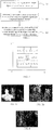
- FIG. 3a shows a depth image taken with a depth camera facing the front of a user
- FIG. 3b shows a depth image taken in a situation where the depth camera and the front of the user have a same orientation.
- the depth image generally includes a plurality of connected regions; and the hand is closest to the depth camera, so the connected region where the hand is located is a connected region with a smallest depth value in the depth image. Accordingly, for example, all the connected regions in the depth image and the minimum depth value of each connected region are detected, and then the connected region having the smallest minimum depth value is taken as the connected region where the hand is located.
- the acquired connected region where the hand is located is shown in the image of the hand in FIG. 4 .
- the connected region where the target object is located is obtained according to any other parameter of the connected region (such as the contour shape, length, area of region or the like of the connected region) except for the minimum depth value.
- the image segmentation method provided by the present disclosure includes the following steps S11 to S14, which are described in detail below.
- Step S11 taking a preset pixel point in the depth image as an initial point and adding the preset pixel point to a preset queue.
- step S11 the preset pixel point is selected by a processor who processes the depth image or is determined by an image processing algorithm.
- the preset queue is an FIFO (First Input First Output) queue, that is, a first-in first-out queue.
- FIFO First Input First Output
- a first-entered instruction is completed and then retires before executing a second instruction, and so on.
- Step S12 determining a neighboring pixel point that is spatially adjacent to the initial point.
- step S12 four neighborhoods or eight neighborhoods of the initial point are detected to determine the neighboring pixel point that is spatially adjacent to the initial point.
- Step S13 calculating an absolute value of a depth difference between the neighboring pixel point and the initial point, in which in a situation where the absolute value of the depth difference is smaller than or equal to a preset depth difference, the neighboring pixel point is added to a connected region where the initial point is located.
- the preset depth difference is from 10 mm to 15 mm, for example, 10 mm, 13 mm or 15 mm, or the like.
- Step S14 taking the neighboring pixel point as a next initial point and adding the neighboring pixel point to the preset queue for a subsequent detection of neighborhoods of the neighboring pixel point.
- step S12 to step S14 are repeated until each pixel point in the preset queue is processed, so as to determine the connected region where the initial point is located. After all the connected regions in the depth image are detected in a similar way, the connected region with the smallest minimum depth value is selected to serve as the connected region where the target object is located.
- the depth values of other pixel points in the depth image except the pixel points in the connected region where the target object is located are set to a null value of 0.
- the depth values of the remaining pixel points are set to 0 except for the pixel points in the connected region where the hand is located.
- step S2 The determination of the principal direction or the secondary direction of the connected region by the principal component analysis method described in step S2 will be described in detail below.
- the principle component analysis (PCA) method is a multivariate statistical analysis method that transforms data into a new coordinate system by linear transformation so that the variance of the data on the first coordinate axis is largest, the variance of the data on the second coordinate axis is second largest, and so on.
- the direction of the first coordinate axis is the principal direction (that is, the principal direction is the direction with the largest variance of the data) and the direction of the other coordinate axis are the secondary direction (the secondary direction is the direction with the variance of the data is not the largest).
- the principal direction obtained by the PCA method of the connected region acquired in step S1 is shown by a white straight line in FIG. 6 .
- step S3 the acquiring the image of the target object from the connected region according to the relationship between the morphology of the target object and the principal direction or the secondary direction in step S3 will be described in detail
- the morphology of the target object is a contour shape, a variation trend of a contour, a size, an area of region, or other parameter of the target object or an object including the target object.
- the morphology of the hand is a variation trend of a contour that gradually narrows from a forearm to a wrist of the hand and gradually widens from the wrist of the hand to a palm of the hand. Therefore, for example, a wrist position is taken as a segmentation position for obtaining an image of the hand from the connected region and removing an image of the arm.
- a suitable segmentation position may be found according to the specific shape of the object.
- the target object is a human head
- the morphology of the human head is a contour shape of the human head, a variation trend of a contour, a length or an area of region because there are obvious differences between the human head and a part of a human body below the human head in the contour shape, in the variation trend of the contour, in the length and in the area of region.
- the relationship between the morphology of the target object and the secondary direction is, for example, a shoulder of the human body has a largest width in the secondary direction which is a direction from a left hand side to a right hand side of the human body. Therefore, for example, the shoulder serves as a segmentation position for obtaining an image of the human head from a connected region where the human body is located.
- the target object is the human hand
- the image of the target object is acquired from the connected region where the target object is located according to the relationship between the morphology of the target object and the principal direction, and the step S3 will be described in detail below.
- the acquiring the image of the target object includes: determining a variation trend of pixel-point numbers respectively at a plurality of different positions in the connected region where the target object is located along the principal direction, in which pixel points at each of the plurality of positions are sequentially arranged along the secondary direction of the connected region, and the secondary direction is perpendicular to the principal direction; comparing the variation trend with a variation trend of the morphology of the target object along the principal direction; and determining a segmentation position for acquiring the image of the target object in the connected region according to a comparison result.
- the variation trend of pixel-point numbers respectively at the plurality of different positions reflects the variation trend of the morphology of the target object along the principal direction, so a suitable segmentation position is determined, for example, by comparing the two variation trends, so as to obtain the image only including the target object from the connected region where the target object is located according to the segmentation position.
- the acquiring the image of the target object in the step S3 includes: determining a real width of the connected region along the secondary direction at each of the plurality of positions, in which the secondary direction is perpendicular to the principal direction, the plurality of positions are sequentially arranged along the principal direction, and pixel points at each of the plurality of positions are sequentially arranged along the secondary direction; and comparing the real width with a reference width to determine the segmentation position for acquiring the image of the target object in the connected region.
- the variation trend of the pixel-point numbers along the principal direction is determined at first, and then the real width of the connected region at each of the plurality of positions is calculated to determine the segmentation position.
- the determination of the variation trend of the pixel-point numbers along the principal direction is omitted, the width variation trend of the connected region along the principal direction is determined according to real widths of the connected region respectively at the plurality of positions, and a position having a real width within a range of the reference width is selected from the plurality of positions, so as to determine the segmentation position.
- a width of the wrist is from 40 mm to 100 mm, so the reference width is from 40 mm to 100 mm, for example, 40 mm, 60 mm, 80 mm or 100 mm.
- the real width of the connected region at each of the plurality of positions is determined.
- the acquiring the image of the target object in the step S3 further includes: determining a real distance from each of the plurality of positions to a vertex of the connected region; and comparing the real distance with a reference length to determine the segmentation position.
- the vertex of the connected region is determined according to the position relationship between the coordinate of the vertex and the principal direction.
- the reference length is from 40 mm to 200 mm because a length of the human hand (a length from a fingertip to the wrist) is, for example, from 40 mm to 200 mm.
- a position having a real distance within a range of the reference length serves as the segmentation position.
- a real distance from each of the plurality of positions to the vertex of the connected region is determined.
- the target object is the human hand
- the acquiring the image of the target object in the step S3 includes, for example, the flowing step S31 to step S 35, which will be described in detail below with reference to FIG. 7 to FIG. 10 .
- Step S31 determining pixel-point numbers respectively at a plurality of different positions in the connected region where the hand is located, the plurality of different positions are arranged sequentially along the principal direction, pixel points at each of the plurality of positions are sequentially arranged along the secondary direction of the connected region, and the secondary direction is perpendicular to the principal direction;
- the original coordinate system of the depth image is rotated based on the principal direction until the Y axis of the new coordinate system (referring to the rectangular coordinate system XOY shown in FIG. 7 ) of the depth image is parallel to the principal direction (for example, the Y axis is oriented in the same direction as or opposite to the principal direction).
- the X axis is parallel to the above secondary direction (as shown by the white line in FIG. 7 ), and all the pixel points in the original depth image are given a new coordinate value under the new coordinate system.
- the pixel-point numbers at these positions are stored in an array disData (k).
- the array disData (k) represents the width variation trend of the connected region where the hand is located in the two-dimensional depth image along the principal direction. According to the width variation trend, along with the variation trend of the morphology of the human hand along the principal direction, a basis is provided to the determining of the wrist and the removing of the arm.
- Step S32 determining a real width of the connected region where the hand is located along the secondary direction at each of the plurality of positions
- the realDis (k) is in millimeters (mm). It should be noted that the "ratio" is the camera's focal distance ratio and is determined according to the camera itself.
- the real width realDis (k) of the connected region at each of the plurality of positions is determined according to the number disData (k) of the pixel points at each of the plurality of positions, the average depth value aveDepth (k) of the pixel points at each of the plurality of positions, and the focal distance ratio "ratio" of the camera for acquiring the depth image, which are obtained in step S31.
- Step S33 determining a real distance from each of the plurality of positions to the vertex of the connected region.
- an array realLenth (n) representing the real length is obtained in this step S33 after obtaining the array realDis (k) representing the real width in step S32.
- Step S34 comparing the real width at each position obtained in step S32 with the reference width of the hand, taking into account of the width variation trend of connected region along the principal direction (for example, the width variation trend is determined according to the pixel-point numbers obtained in step S31 or the real widths respectively at the positions obtained in the step S32), and comparing the real distance from each position to the vertex of the connected region obtained in the step S33 with the reference length of the hand, so as to determine the wrist position (an example of the segmentation position).
- the width variation trend is determined according to the pixel-point numbers obtained in step S31 or the real widths respectively at the positions obtained in the step S32
- the reference width of the wrist is from 40 mm to 100 mm, for example, 40 mm, 80 mm or 100 mm.
- the reference length of the hand is from 40 mm to 200 mm.
- the reference position indicated by the upper white line is not suitable as the segmentation position; the reference position indicated by the lower white line below is suitable as the segmentation position; and both of the reference positions have a width close to the wrist width, satisfy the characteristic that the width of the connected region widens from the part of the connected region below each of the reference positions to the part of the connected region above each of the reference positions, and have a segmentation length within the range from the minimum value of the hand to the maximum value of the hand.
- a segmentation error may occur, for example, it is possible to get only 4 fingers according to the upper reference position in FIG. 8 .
- the inventors of the present application found that, for a human hand, there is a null value between a part of adjacent pixel points at a reference position unsuitable as a segmentation position (for example, the upper reference position in FIG. 8 ); thus, during calculating the number of pixel points, at the reference position unsuitable as the segmentation position, the difference (which is a positive value) obtained by subtracting the coordinates of two furthest pixel points in the connected region where the hand is located is significantly greater than the number of the pixel points at the reference position; and at the reference position suitable as the segmentation position (as shown by the lower reference position in FIG. 8 ), the difference obtained by subtracting the coordinates of the two pixel points farthest apart in the connected region where the hand is located is roughly equal to the number of the pixel points at the reference position.
- the acquiring the image of the target object in the step S3 further includes: obtaining a plurality of reference positions among the plurality of positions; calculating a difference (the difference is positive value) between coordinates of two pixel points which are farthest away from each other at each of the reference positions; and determining the segment position according to a size relationship between the difference of the coordinates and the number of pixel points at each of the reference positions.
- the plurality of reference positions include a first reference position and a second reference position, a difference between coordinates of two pixel points farthest away from each other at the first reference position is ⁇ X1 ( ⁇ X1 is greater than 0), the number of pixel points at the first reference position is N1, and in a situation where ( ⁇ X1-N1) / N1 is smaller than or equal to a preset value which is from 10% to 15%, the first reference position is taken as the segmentation position.
- the segmentation position is selected from the first reference position and the second reference position.
- the lower reference position in FIG. 8 is determined to be the segmentation position and the upper reference position in FIG. 8 is determined to be not suitable as the segmentation position.
- the embodiments of the preset value include, but are not limited to, 10% to 15%, and may be set according to actual needs.
- the inventors of the present application also found that, for a human hand, in a situation where at least three reference positions are obtained, for example, the first reference position, the second reference position and a third reference position, after the second reference position is determined to be not suitable as the segmentation position according to the size relationship between the difference of the coordinates and the number of pixel points, and in a case that the distance between the third reference position and the second reference position along the principal direction is smaller than or equal to a preset distance (for example, 24 mm - 26 mm), the third reference position is also not suitable as a segmentation position.
- a preset distance for example, 24 mm - 26 mm
- a difference between coordinates of two pixel points farthest away from each other at the second reference position is ⁇ X2 ( ⁇ X2 is greater than 0), the number of pixel points at the second reference position is N2, and in a situation where ( ⁇ X2-N2) / N2 is greater than the above preset value (for example, greater than 15%) and where the distance from the third reference position (the third reference position is between the vertex of the connected region and the second reference position or is at a side of the second reference position away from the vertex of the connected region) to the second reference position is smaller than or equal to the preset distance, the third reference position is not selected to be the segmentation position, namely the distance from an appropriate segmentation position to the second reference position is greater than the preset distance.
- the preset distance is from 24 mm to 26 mm, for example, 24 mm, 25 mm or 26 mm.
- FIG. 9 four reference positions are shown in FIG. 9 , the four reference positions are sequentially numbered from top to bottom as 1, 2, 3, and 4, reference positions 1 to 3 are not suitable for serving as the segmentation position, and reference position 4 is used as the segmentation position.
- the reference positions are sequentially evaluated in the principal direction (namely, starting from the vertex of the connected region).
- the reference position 1 is not suitable as the segment position according to the size relationship between the number of pixel points and the difference between the coordinates of the pixel points; then, it is determined that the reference position 2 is not suitable as the segmentation position based on the size relationship between the distance from the reference position 2 to the reference position 1 and the preset value; and afterwards, it is judged that the reference position 3 is not suitable as the segmentation position according to the size relationship between the difference of coordinates and the number of pixel points, and thus it is obtained that the reference position 4 is suitable as the segmentation position.
- Step S35 after the wrist position is determined by step S34, acquiring the image of the hand from the connected region where the hand is located and removing the image of the arm according to the wrist position. For example, a relatively good image of the hand shown in FIG. 10 is obtained.
- a flow chart of a method is summarized as FIG. 11 , that is, the method includes: extracting the connected region from the depth image, then determining the principal direction of the connected region via the PCA method, afterwards calculating the real width and the real length of the connected region, then determining the segmentation position according to heuristic characteristics and finally acquiring the image of the hand from the connected region.
- the heuristic characteristics include: the reference width of the hand, the reference length of the hand, the variation trend of the width of the connected region where the hand is located in the principal direction, the fact that a null value occurs at a reference position unsuitable as the segmentation position and causes a large difference between the coordinate difference of pixel points farthest away from each other at the reference position and the number of pixel points at the reference position, and the fact that a reference position is not suitable as the segmentation position in a situation where the distance from the reference position to another reference position unsuitable as the segmentation position is smaller than or equal to the preset distance (for example, 24 mm - 26 mm), and so on.
- the preset distance for example, 24 mm - 26 mm
- the present disclosure further provides an image segmentation system, as shown in FIG. 12 , the image segmentation system includes: a first image segmentation device configured to process a depth image to obtain a connected region where a target object is located from the depth image; an analysis device connected to the first image segmentation device and configured to determine a principal direction or a secondary direction of the connected region acquired by the first image segmentation device by a principal component analysis method; and a second image segmentation device connected to the analysis device and configured to acquire an image of the target object (for example, a hand) from the connected region according to relationship between morphology of the target object and the principal direction or the secondary direction .
- a first image segmentation device configured to process a depth image to obtain a connected region where a target object is located from the depth image
- an analysis device connected to the first image segmentation device and configured to determine a principal direction or a secondary direction of the connected region acquired by the first image segmentation device by a principal component analysis method
- a second image segmentation device connected to the analysis device and configured to acquire
- the second image segmentation device includes a calculator device connected to the analysis device and a comparison device connected to the calculator device.
- the calculator device is configured to calculate pixel-point numbers respectively at a plurality of positions in the connected region and to determine a variation trend of the point-pixel numbers along the principal direction, pixel points at each of the plurality of positions are sequentially arranged along the secondary direction of the connected region, and the secondary direction is perpendicular to the principal direction; and accordingly, the comparison device is configured to compare the variation trend with a variation trend of the morphology of the target object along the principal direction, to determine a segmentation position for acquiring the image of the target object in the connected region.
- the calculator device is configured to calculate a real width of the connected region along the secondary direction at each of a plurality of positions, the secondary direction is perpendicular to the principal direction, the plurality of positions are sequentially arranged along the principal direction, and the pixel points at each of the plurality of positions are sequentially arranged along the secondary direction; and accordingly, the comparison device is configured to compare the real width with a reference width to determine a segmentation position for acquiring the image of the target object in the connected region.
- the reference width is from 40 mm to 100 mm, for example, 40 mm, 80 mm or 100 mm.
- the calculator device is configured not only to determine the variation trend of the point-pixel numbers along the principal direction, but also to determine the real width of the connected region along the secondary direction at each of the plurality of positions; and accordingly, the comparison device is configured not only to compare the variation trend of the point-pixel numbers along the principal direction with the variation trend of the morphology of the target object along the principal direction, but also to compare the real width of the connected region at each of the plurality of positions with the reference width, to determine the segmentation position.
- the calculator device is further configured to calculate a real distance from each of the plurality of positions to a vertex of the connected region, and the comparison device is accordingly further configured to compare the real distance with a reference length to determine the segmentation position.
- the target object being a human hand
- the reference length is from 40 mm to 200 mm.
- the image segmentation system further includes a depth camera configured to acquire the depth image and to output the depth image to the first image segmentation device.
- each of the specific structures of the first image segmentation device, the analysis device, the second image segmentation device, the calculator device, and the comparison device in the image segmentation system is a processor, such as a processor comprising hardware.
- the processor is an electronic component or a collection of electronic components having a processing function such as a central processing unit (CPU), a micro controller unit (MCU), a digital signal processing (DSP), or a programmable logic controller (PLC).
- CPU central processing unit
- MCU micro controller unit
- DSP digital signal processing
- PLC programmable logic controller
- the above devices of the present disclosure may all be integrated in one processor or may be implemented by different processors respectively, or any two or more devices may be integrated in one processor.
- the above devices may be implemented in the form of hardware, or may be implemented in the form of hardware plus software functional unit.
- At least one embodiment of the present disclosure further provides an image segmentation system as specified in claim 12 and as illustrated in FIG. 13 .
- the memory includes at least one of read-only memory and random access memory and provides instructions and data to the processor.
- a portion of the memory also includes non-volatile random access memory (NVRAM).
- NVRAM non-volatile random access memory
- the processor may be a general purpose processor, a digital signal processor (DSP), an application specific integrated circuit (ASIC), a field programmable gate array (FPGA) or other programmable logic device, discrete gate or transistor logic, discrete hardware components.
- DSP digital signal processor
- ASIC application specific integrated circuit
- FPGA field programmable gate array
- the general purpose processor may be a microprocessor or any conventional processor or the like.
- the image segmentation system further includes a depth camera configured to acquire the depth image and to output the depth image to the first image segmentation device.
- At least one embodiment of the present disclosure further provides a storage medium as specified in claim 13.
- the storage medium may be a semiconductor memory, a magnetic surface memory, a laser memory, a random access memory, a read only memory, a serial access memory, a non-permanent memory, a permanent memory, or any other form of storage medium well known in the art.
- the processor may be a general purpose processor, a digital signal processor (DSP), an application specific integrated circuit (ASIC), a field programmable gate array (FPGA) or other programmable logic device, discrete gate or transistor logic, discrete hardware components.
- DSP digital signal processor
- ASIC application specific integrated circuit
- FPGA field programmable gate array
- the general purpose processor may be a microprocessor or any conventional processor or the like.
- At least one embodiment of the present disclosure further provides an apparatus as specified in claim 14.
- the apparatus is a human-machine interaction device such as an AR smart glasses or a display.
- the device acquires an image including an instruction of a user (for example, the image of the target object) by using the image segmentation system included in the apparatus, and realizes the human-computer interaction by analyzing and processing the image.
Landscapes
- Engineering & Computer Science (AREA)
- Physics & Mathematics (AREA)
- General Physics & Mathematics (AREA)
- Theoretical Computer Science (AREA)
- Computer Vision & Pattern Recognition (AREA)
- Multimedia (AREA)
- Human Computer Interaction (AREA)
- Geometry (AREA)
- Health & Medical Sciences (AREA)
- General Health & Medical Sciences (AREA)
- Psychiatry (AREA)
- Social Psychology (AREA)
- Image Analysis (AREA)
Claims (14)
- Bildsegmentierungsverfahren, das von einem Prozessor ausgeführt wird, wobei das Verfahren aufweist:Abrufen einer zusammenhängenden Region, in der sich ein Zielobjekt befindet, aus einem Tiefenbild;Bestimmen einer Hauptrichtung und einer Nebenrichtung der zusammenhängenden Region durch ein Hauptkomponentenanalyseverfahren; undErfassen eines Bildes des Zielobjekts aus der zusammenhängenden Region gemäß der Beziehung zwischen der Morphologie des Zielobjekts und der Hauptrichtung,wobei das Erfassen des Bildes des Zielobjekts aufweist:Bestimmen einer realen Breite der zusammenhängenden Region entlang der Nebenrichtung an jeder einer Vielzahl von Positionen, wobei die Nebenrichtung senkrecht zu der Hauptrichtung ist, die Vielzahl von Positionen sequentiell entlang der Hauptrichtung angeordnet sind, und Pixelpunkte der zusammenhängenden Region an jeder der Vielzahl von Positionen sequentiell entlang der Nebenrichtung angeordnet sind; undVergleichen der realen Breite mit einer Referenzbreite, um eine Vielzahl von Referenzpositionen unter der Vielzahl von Positionen zu bestimmen;Bestimmen eines realen Abstandes von jeder der Vielzahl von Referenzpositionen zu einem Scheitelpunkt der zusammenhängenden Region;Vergleichen des realen Abstandes mit einer Referenzlänge, um mindestens eine Referenzposition aus der Vielzahl von Referenzpositionen auszuwählen;Berechnen einer Differenz zwischen den Koordinaten von zwei Pixelpunkten der zusammenhängenden Region, die an jeder der mindestens einen Referenzposition am weitesten voneinander entfernt sind; undBestimmen einer Segmentierungsposition zum Erfassen des Bildes des Zielobjekts von mindestens einer Referenzposition, gemäß einem Größenverhältnis zwischen der Differenz der Koordinaten und der Anzahl von Pixelpunkten der zusammenhängenden Region an jeder der mindestens einen Referenzposition; wobeidas Zielobjekt eine menschliche Hand ist, die Referenzbreite von 40 mm bis 100 mm beträgt und die Referenzlänge von 40 mm bis 200 mm beträgt,wobeigemäß einer Anzahl der Pixelpunkte der zusammenhängenden Region an jeder der mehreren Positionen, einem durchschnittlichen Tiefenwert der Pixelpunkte der zusammenhängenden Region an jeder der mehreren Positionen und einem Brennweitenverhältnis einer Kamera zum Erfassen des Tiefenbildes die tatsächliche Breite der zusammenhängenden Region an jeder der mehreren Positionen bestimmt wird, undgemäß einer Differenz zwischen durchschnittlichen Tiefenwerten von und einem realen Abstand entlang der Hauptrichtung jeder Gruppe von zwei benachbarten der Positionen zwischen jeder der Vielzahl von Positionen und dem Scheitelpunkt der zusammenhängenden Region ein realer Abstand von jeder der Vielzahl von Positionen zum Scheitelpunkt der zusammenhängenden Region bestimmt wird.
- Verfahren nach Anspruch 1, wobei das Abrufen der zusammenhängenden Region, in der sich das Zielobjekt befindet, aus dem Tiefenbild aufweist:Erfassen aller zusammenhängenden Regionen in dem Tiefenbild und eines gleichen Parameters jeder der zusammenhängenden Regionen; undErfassen einer zusammenhängenden Region mit einem voreingestellten Parameter als die zusammenhängenden Region, in der sich das Zielobjekt befindet.
- Verfahren nach Anspruch 1 oder 2, ferner aufweisend:Schritt S11: Nehmen eines voreingestellten Pixelpunktes in dem Tiefenbild als einen Anfangspunkt und Hinzufügen des voreingestellten Pixelpunktes zu einer voreingestellten Warteschlange;Schritt S12: Bestimmen eines benachbarten Pixelpunkts, der räumlich an den Anfangspunkt angrenzt;Schritt S13: Berechnen eines Absolutwerts einer Tiefendifferenz zwischen dem benachbarten Pixelpunkt und dem Anfangspunkt, wobei in einer Situation, in der der Absolutwert der Tiefendifferenz kleiner als oder gleich einer voreingestellten Tiefendifferenz ist, der benachbarte Pixelpunkt zu einer zusammenhängenden Region hinzugefügt wird, in der sich der Anfangspunkt befindet;Schritt S14: Nehmen des benachbarten Pixelpunkts als einen nächsten Anfangspunkt und Hinzufügen des benachbarten Pixelpunkts zu der voreingestellten Warteschlange; undWiederholen des obigen Schritts S12 bis Schritt S14, um die zusammenhängende Region zu bestimmen, in der sich der Anfangspunkt befindet.
- Verfahren nach Anspruch 1, wobei
die mehreren Bezugspositionen eine erste Bezugsposition und eine zweite Bezugsposition aufweisen, eine Differenz zwischen Koordinaten von zwei am weitesten voneinander entfernten Pixelpunkten der zusammenhängenden Region an der ersten Bezugsposition ΔX1 ist, die größer als 0 ist, die Anzahl der Pixelpunkte der zusammenhängenden Region an der ersten Bezugsposition N1 ist, und
in einer Situation, in der (ΔX1-N1) / N1 kleiner oder gleich einem voreingestellten Wert ist, der zwischen 10% und 15% liegt, die erste Referenzposition als die Segmentierungsposition genommen wird. - Bildsegmentierungsverfahren, das von einem Prozessor ausgeführt wird, wobei das Verfahren aufweist
Abrufen einer zusammenhängenden Region, in der sich ein Zielobjekt befindet, aus einem Tiefenbild;
Bestimmen einer Hauptrichtung und einer Nebenrichtung der zusammenhängenden Region durch ein Hauptkomponentenanalyseverfahren; und
Erfassen eines Bildes des Zielobjekts aus der zusammenhängenden Region gemäß der Beziehung zwischen der Morphologie des Zielobjekts und der Hauptrichtung,
wobei das Erfassen des Bildes des Zielobjekts aufweist:Bestimmen eines Variationstrends von Pixelpunktzahlen jeweils an einer Vielzahl von Positionen in der zusammenhängenden Region entlang der Hauptrichtung, wobei Pixelpunkte der zusammenhängenden Region an jeder der Vielzahl von Positionen sequentiell entlang der Sekundärrichtung der zusammenhängenden Region angeordnet sind und die Sekundärrichtung senkrecht zu der Hauptrichtung ist;Vergleichen des Veränderungstrends mit einem Veränderungstrend der Morphologie des Zielobjekts entlang der Hauptrichtung; undBestimmen einer Mehrzahl von Referenzpositionen unter der Mehrzahl von Positionen in der zusammenhängenden Region gemäß einem Vergleichsergebnis;Bestimmen eines realen Abstandes von jeder der Vielzahl von Referenzpositionen zu einem Scheitelpunkt der zusammenhängenden Region;Vergleichen des realen Abstandes mit einer Referenzlänge, um mindestens eine Referenzposition aus der Vielzahl von Referenzpositionen auszuwählen;Berechnen einer Differenz zwischen den Koordinaten von zwei Pixelpunkten der zusammenhängenden Region, die an jeder der mindestens einen Referenzposition am weitesten voneinander entfernt sind; undBestimmen einer Segmentierungsposition zum Erfassen des Bildes des Zielobjekts von mindestens einer Referenzposition, gemäß einem Größenverhältnis zwischen der Differenz der Koordinaten und der Anzahl von Pixelpunkten der zusammenhängenden Region an jeder der mindestens einen Referenzposition;wobei das Zielobjekt eine menschliche Hand ist, undwobei gemäß einer Differenz zwischen durchschnittlichen Tiefenwerten von und einem realen Abstand entlang der Hauptrichtung jeder Gruppe von zwei benachbarten der Positionen zwischen jeder der Vielzahl von Positionen und dem Scheitelpunkt der zusammenhängenden Region ein realer Abstand von jeder der Vielzahl von Positionen zu dem Scheitelpunkt der zusammenhängenden Region bestimmt wird. - Verfahren nach Anspruch 5, wobei das Abrufen der zusammenhängenden Region, in der sich das Zielobjekt befindet, aus dem Tiefenbild aufweist:Erfassen aller zusammenhängenden Regionen in dem Tiefenbild und eines gleichen Parameters jeder der zusammenhängenden Regionen; undErfassen einer zusammenhängenden Region mit einem voreingestellten Parameter als die zusammenhängenden Region, in der sich das Zielobjekt befindet.
- Verfahren nach Anspruch 5 oder 6, ferner aufweisend:Schritt S11: Nehmen eines voreingestellten Pixelpunktes in dem Tiefenbild als einen Anfangspunkt und Hinzufügen des voreingestellten Pixelpunktes zu einer voreingestellten Warteschlange;Schritt S12: Bestimmen eines benachbarten Pixelpunkts, der räumlich an den Anfangspunkt angrenzt;Schritt S13: Berechnen eines Absolutwerts einer Tiefendifferenz zwischen dem benachbarten Pixelpunkt und dem Anfangspunkt, wobei in einer Situation, in der der Absolutwert der Tiefendifferenz kleiner als oder gleich einer voreingestellten Tiefendifferenz ist, der benachbarte Pixelpunkt zu einer zusammenhängenden Region hinzugefügt wird, in der sich der Anfangspunkt befindet;Schritt S14: Nehmen des benachbarten Pixelpunkts als einen nächsten Anfangspunkt und Hinzufügen des benachbarten Pixelpunkts zu der voreingestellten Warteschlange; undWiederholen des obigen Schritts S12 bis Schritt S14, um die zusammenhängende Region zu bestimmen, in der sich der Anfangspunkt befindet.
- Verfahren nach Anspruch 5, wobei
die mehreren Bezugspositionen eine erste Bezugsposition und eine zweite Bezugsposition aufweisen, eine Differenz zwischen Koordinaten von zwei am weitesten voneinander entfernten Pixelpunkten der zusammenhängenden Region an der ersten Bezugsposition ΔX1 ist, die größer als 0 ist, die Anzahl der Pixelpunkte der zusammenhängenden Region an der ersten Bezugsposition N1 ist, und
in einer Situation, in der (ΔX1-N1) /N1 kleiner oder gleich einem voreingestellten Wert ist, der zwischen 10% und 15% liegt, wird die erste Referenzposition als die Segmentierungsposition genommen. - Verfahren nach Anspruch 2 oder 6, wobei
der gleiche Parameter ein minimaler Tiefenwert ist, und der voreingestellte Parameter ein minimaler Tiefenwert ist, der unter den minimalen Tiefenwerten der zusammenhängenden Regionen am kleinsten ist. - Verfahren nach Anspruch 3 oder 7, wobei
die voreingestellte Tiefendifferenz zwischen 10 mm und 15 mm liegt. - Verfahren nach Anspruch 4 oder 8, wobei
eine Differenz zwischen den Koordinaten von zwei am weitesten voneinander entfernten Pixelpunkten der zusammenhängenden Region an der zweiten Referenzposition ΔX2 ist, die größer als 0 ist, die Anzahl der Pixelpunkte der zusammenhängenden Region an der zweiten Referenzposition N2 ist, und
in einer Situation, in der (ΔX2-N2) / N2 größer als der voreingestellte Wert ist, ein Abstand von der Segmentierungsposition zu der zweiten Referenzposition größer als ein voreingestellter Abstand ist, und der voreingestellte Abstand von 24 mm bis 26 mm ist. - Bildsegmentierungssystem, das Folgendes aufweist:einen Prozessor;einen Speicher; undeinen Computerprogrammbefehl, der in dem Speicher gespeichert ist, wobei der Prozessor so konfiguriert ist, dass er den Computerprogrammbefehl ausführt, um das Bildsegmentierungsverfahren nach einem der Ansprüche 1-11 auszuführen.
- Speichermedium, in dem ein Computerprogrammbefehl gespeichert ist, wobei der Computerprogrammbefehl, wenn er von einem Prozessor ausgeführt wird, den Prozessor veranlasst, das Bildsegmentierungsverfahren nach einem der Ansprüche 1-11 auszuführen.
- Vorrichtung, aufweisend das Bildsegmentierungssystem nach Anspruch 12.
Applications Claiming Priority (2)
| Application Number | Priority Date | Filing Date | Title |
|---|---|---|---|
| CN201610905435.XA CN107958458B (zh) | 2016-10-17 | 2016-10-17 | 图像分割方法、图像分割系统及包括其的设备 |
| PCT/CN2017/091986 WO2018072483A1 (zh) | 2016-10-17 | 2017-07-06 | 图像分割方法、图像分割系统和存储介质及包括其的设备 |
Publications (3)
| Publication Number | Publication Date |
|---|---|
| EP3537375A1 EP3537375A1 (de) | 2019-09-11 |
| EP3537375A4 EP3537375A4 (de) | 2020-07-08 |
| EP3537375B1 true EP3537375B1 (de) | 2021-09-01 |
Family
ID=61953939
Family Applications (1)
| Application Number | Title | Priority Date | Filing Date |
|---|---|---|---|
| EP17835447.8A Active EP3537375B1 (de) | 2016-10-17 | 2017-07-06 | Bildsegmentierungsverfahren, bildsegmentierungssystem und vorrichtung damit, und speichermedium |
Country Status (4)
| Country | Link |
|---|---|
| US (1) | US10650523B2 (de) |
| EP (1) | EP3537375B1 (de) |
| CN (1) | CN107958458B (de) |
| WO (1) | WO2018072483A1 (de) |
Families Citing this family (16)
| Publication number | Priority date | Publication date | Assignee | Title |
|---|---|---|---|---|
| US10803616B1 (en) | 2017-04-13 | 2020-10-13 | Facebook Technologies, Llc | Hand calibration using single depth camera |
| CN109426789B (zh) * | 2017-08-31 | 2022-02-01 | 京东方科技集团股份有限公司 | 手和图像检测方法和系统、手分割方法、存储介质和设备 |
| US11957975B2 (en) * | 2018-05-24 | 2024-04-16 | Microsoft Technology Licensing, Llc | Dead reckoning and latency improvement in 3D game streaming scenario |
| CN108876795A (zh) * | 2018-06-07 | 2018-11-23 | 四川斐讯信息技术有限公司 | 一种图像中物体的分割方法及系统 |
| CN109003282B (zh) * | 2018-07-27 | 2022-04-29 | 京东方科技集团股份有限公司 | 一种图像处理的方法、装置及计算机存储介质 |
| CN109048918B (zh) * | 2018-09-25 | 2022-02-22 | 华南理工大学 | 一种轮椅机械臂机器人的视觉引导方法 |
| CN110390666B (zh) * | 2019-06-14 | 2023-06-27 | 平安科技(深圳)有限公司 | 道路损伤检测方法、装置、计算机设备及存储介质 |
| CN110544256B (zh) * | 2019-08-08 | 2022-03-22 | 北京百度网讯科技有限公司 | 基于稀疏特征的深度学习图像分割方法及装置 |
| CN112711250B (zh) * | 2019-10-25 | 2022-07-05 | 科沃斯机器人股份有限公司 | 一种自行走设备移动控制方法与自行走设备 |
| CN112907569B (zh) * | 2021-03-24 | 2024-03-15 | 贝壳找房(北京)科技有限公司 | 头部图像区域的分割方法、装置、电子设备和存储介质 |
| CN113129305B (zh) * | 2021-05-18 | 2023-06-16 | 浙江大华技术股份有限公司 | 丝锭状态的确定方法、装置、存储介质及电子装置 |
| CN113436175B (zh) * | 2021-06-30 | 2023-08-18 | 平安科技(深圳)有限公司 | 车图像分割质量的评估方法、装置、设备及存储介质 |
| CN114299406B (zh) * | 2022-03-07 | 2022-06-07 | 山东鹰联光电科技股份有限公司 | 基于无人机航拍的光纤电缆线路巡检方法 |
| CN114842033B (zh) * | 2022-06-29 | 2022-09-02 | 江西财经大学 | 一种用于智能ar设备的图像处理方法 |
| CN116703251B (zh) * | 2023-08-08 | 2023-11-17 | 德润杰(山东)纺织科技有限公司 | 基于人工智能的胶圈生产质量检测方法 |
| CN118123228B (zh) * | 2024-05-07 | 2024-08-06 | 东莞市晨兴智能精密装备有限公司 | 一种基于激光定位的高精度加工方法及装置 |
Family Cites Families (12)
| Publication number | Priority date | Publication date | Assignee | Title |
|---|---|---|---|---|
| US8379987B2 (en) | 2008-12-30 | 2013-02-19 | Nokia Corporation | Method, apparatus and computer program product for providing hand segmentation for gesture analysis |
| US9417700B2 (en) * | 2009-05-21 | 2016-08-16 | Edge3 Technologies | Gesture recognition systems and related methods |
| US8625897B2 (en) | 2010-05-28 | 2014-01-07 | Microsoft Corporation | Foreground and background image segmentation |
| CN102831378B (zh) * | 2011-06-14 | 2015-10-21 | 株式会社理光 | 人的检测和跟踪方法与系统 |
| CN102867311B (zh) * | 2011-07-07 | 2015-11-25 | 株式会社理光 | 目标跟踪方法和目标跟踪设备 |
| EP2680228B1 (de) * | 2012-06-25 | 2014-11-26 | Softkinetic Software | Verbesserungen bei oder im Zusammenhang mit dreidimensionalen nahen Interaktionen |
| US9152243B2 (en) * | 2012-08-23 | 2015-10-06 | Qualcomm Incorporated | Object tracking using background and foreground models |
| US9311550B2 (en) * | 2013-03-06 | 2016-04-12 | Samsung Electronics Co., Ltd. | Device and method for image processing |
| CN104217192B (zh) * | 2013-06-03 | 2018-04-17 | 株式会社理光 | 基于深度图像的手定位方法和设备 |
| CN104765440B (zh) * | 2014-01-02 | 2017-08-11 | 株式会社理光 | 手检测方法和设备 |
| RU2014108870A (ru) * | 2014-03-06 | 2015-09-20 | ЭлЭсАй Корпорейшн | Процессор изображений, содержащий систему распознавания жестов с распознаванием неподвижной позы кисти на основе первого и второго наборов признаков |
| CN105096259B (zh) * | 2014-05-09 | 2018-01-09 | 株式会社理光 | 深度图像的深度值恢复方法和系统 |
-
2016
- 2016-10-17 CN CN201610905435.XA patent/CN107958458B/zh active Active
-
2017
- 2017-07-06 WO PCT/CN2017/091986 patent/WO2018072483A1/zh unknown
- 2017-07-06 US US15/750,410 patent/US10650523B2/en active Active
- 2017-07-06 EP EP17835447.8A patent/EP3537375B1/de active Active
Also Published As
| Publication number | Publication date |
|---|---|
| EP3537375A4 (de) | 2020-07-08 |
| US10650523B2 (en) | 2020-05-12 |
| WO2018072483A1 (zh) | 2018-04-26 |
| EP3537375A1 (de) | 2019-09-11 |
| CN107958458A (zh) | 2018-04-24 |
| CN107958458B (zh) | 2021-01-22 |
| US20190043199A1 (en) | 2019-02-07 |
Similar Documents
| Publication | Publication Date | Title |
|---|---|---|
| EP3537375B1 (de) | Bildsegmentierungsverfahren, bildsegmentierungssystem und vorrichtung damit, und speichermedium | |
| US10430951B2 (en) | Method and device for straight line detection and image processing | |
| EP3678046B1 (de) | Handdetektionsverfahren und system, bilddetektionsverfahren und system, handsegmentierungsverfahren, speichermedium und vorrichtung | |
| CN108875534B (zh) | 人脸识别的方法、装置、系统及计算机存储介质 | |
| US20150253864A1 (en) | Image Processor Comprising Gesture Recognition System with Finger Detection and Tracking Functionality | |
| WO2015149712A1 (zh) | 一种指向交互方法、装置及系统 | |
| CN112508037B (zh) | 图像模板匹配方法、装置及存储装置 | |
| CN112336342B (zh) | 手部关键点检测方法、装置及终端设备 | |
| CN112633084B (zh) | 人脸框确定方法、装置、终端设备及存储介质 | |
| EP2704056A2 (de) | Bildverarbeitungsvorrichtung, Bildverarbeitungsverfahren | |
| CN113780201B (zh) | 手部图像的处理方法及装置、设备和介质 | |
| WO2018176514A1 (zh) | 指纹配准方法及装置 | |
| JP6487642B2 (ja) | 手指形状の検出方法、そのプログラム、そのプログラムの記憶媒体、及び、手指の形状を検出するシステム。 | |
| CN110363817A (zh) | 目标位姿估计方法、电子设备和介质 | |
| US10922535B2 (en) | Method and device for identifying wrist, method for identifying gesture, electronic equipment and computer-readable storage medium | |
| CN110832542A (zh) | 识别处理设备、识别处理方法和程序 | |
| CN107272899B (zh) | 一种基于动态手势的vr交互方法、装置及电子设备 | |
| CN107153806B (zh) | 一种人脸检测方法及装置 | |
| CN106406507B (zh) | 图像处理方法以及电子设备 | |
| EP2887261B1 (de) | Informationsverarbeitungsvorrichtung, Informationsverarbeitungsverfahren und Programm | |
| CN111709269B (zh) | 一种深度图像中基于二维关节信息的人手分割方法和装置 | |
| JP5051671B2 (ja) | 情報処理装置、情報処理方法およびプログラム | |
| US10140509B2 (en) | Information processing for detection and distance calculation of a specific object in captured images | |
| CN113128324B (zh) | 基于深度数据的手势分割方法及其系统和电子设备 | |
| CN113033256B (zh) | 一种指尖检测模型的训练方法和设备 |
Legal Events
| Date | Code | Title | Description |
|---|---|---|---|
| STAA | Information on the status of an ep patent application or granted ep patent |
Free format text: STATUS: UNKNOWN |
|
| STAA | Information on the status of an ep patent application or granted ep patent |
Free format text: STATUS: THE INTERNATIONAL PUBLICATION HAS BEEN MADE |
|
| PUAI | Public reference made under article 153(3) epc to a published international application that has entered the european phase |
Free format text: ORIGINAL CODE: 0009012 |
|
| STAA | Information on the status of an ep patent application or granted ep patent |
Free format text: STATUS: REQUEST FOR EXAMINATION WAS MADE |
|
| 17P | Request for examination filed |
Effective date: 20180205 |
|
| AK | Designated contracting states |
Kind code of ref document: A1 Designated state(s): AL AT BE BG CH CY CZ DE DK EE ES FI FR GB GR HR HU IE IS IT LI LT LU LV MC MK MT NL NO PL PT RO RS SE SI SK SM TR |
|
| AX | Request for extension of the european patent |
Extension state: BA ME |
|
| DAV | Request for validation of the european patent (deleted) | ||
| DAX | Request for extension of the european patent (deleted) | ||
| A4 | Supplementary search report drawn up and despatched |
Effective date: 20200608 |
|
| RIC1 | Information provided on ipc code assigned before grant |
Ipc: G06T 7/194 20170101ALI20200603BHEP Ipc: G06T 7/62 20170101ALI20200603BHEP Ipc: G06T 7/11 20170101AFI20200603BHEP |
|
| GRAP | Despatch of communication of intention to grant a patent |
Free format text: ORIGINAL CODE: EPIDOSNIGR1 |
|
| STAA | Information on the status of an ep patent application or granted ep patent |
Free format text: STATUS: GRANT OF PATENT IS INTENDED |
|
| INTG | Intention to grant announced |
Effective date: 20210215 |
|
| GRAS | Grant fee paid |
Free format text: ORIGINAL CODE: EPIDOSNIGR3 |
|
| RAP3 | Party data changed (applicant data changed or rights of an application transferred) |
Owner name: BOE TECHNOLOGY GROUP CO., LTD. |
|
| GRAA | (expected) grant |
Free format text: ORIGINAL CODE: 0009210 |
|
| STAA | Information on the status of an ep patent application or granted ep patent |
Free format text: STATUS: THE PATENT HAS BEEN GRANTED |
|
| AK | Designated contracting states |
Kind code of ref document: B1 Designated state(s): AL AT BE BG CH CY CZ DE DK EE ES FI FR GB GR HR HU IE IS IT LI LT LU LV MC MK MT NL NO PL PT RO RS SE SI SK SM TR |
|
| REG | Reference to a national code |
Ref country code: GB Ref legal event code: FG4D |
|
| REG | Reference to a national code |
Ref country code: CH Ref legal event code: EP Ref country code: AT Ref legal event code: REF Ref document number: 1427013 Country of ref document: AT Kind code of ref document: T Effective date: 20210915 |
|
| REG | Reference to a national code |
Ref country code: DE Ref legal event code: R096 Ref document number: 602017045373 Country of ref document: DE |
|
| REG | Reference to a national code |
Ref country code: IE Ref legal event code: FG4D |
|
| REG | Reference to a national code |
Ref country code: LT Ref legal event code: MG9D |
|
| REG | Reference to a national code |
Ref country code: NL Ref legal event code: MP Effective date: 20210901 |
|
| PG25 | Lapsed in a contracting state [announced via postgrant information from national office to epo] |
Ref country code: SE Free format text: LAPSE BECAUSE OF FAILURE TO SUBMIT A TRANSLATION OF THE DESCRIPTION OR TO PAY THE FEE WITHIN THE PRESCRIBED TIME-LIMIT Effective date: 20210901 Ref country code: RS Free format text: LAPSE BECAUSE OF FAILURE TO SUBMIT A TRANSLATION OF THE DESCRIPTION OR TO PAY THE FEE WITHIN THE PRESCRIBED TIME-LIMIT Effective date: 20210901 Ref country code: HR Free format text: LAPSE BECAUSE OF FAILURE TO SUBMIT A TRANSLATION OF THE DESCRIPTION OR TO PAY THE FEE WITHIN THE PRESCRIBED TIME-LIMIT Effective date: 20210901 Ref country code: ES Free format text: LAPSE BECAUSE OF FAILURE TO SUBMIT A TRANSLATION OF THE DESCRIPTION OR TO PAY THE FEE WITHIN THE PRESCRIBED TIME-LIMIT Effective date: 20210901 Ref country code: FI Free format text: LAPSE BECAUSE OF FAILURE TO SUBMIT A TRANSLATION OF THE DESCRIPTION OR TO PAY THE FEE WITHIN THE PRESCRIBED TIME-LIMIT Effective date: 20210901 Ref country code: NO Free format text: LAPSE BECAUSE OF FAILURE TO SUBMIT A TRANSLATION OF THE DESCRIPTION OR TO PAY THE FEE WITHIN THE PRESCRIBED TIME-LIMIT Effective date: 20211201 Ref country code: LT Free format text: LAPSE BECAUSE OF FAILURE TO SUBMIT A TRANSLATION OF THE DESCRIPTION OR TO PAY THE FEE WITHIN THE PRESCRIBED TIME-LIMIT Effective date: 20210901 Ref country code: BG Free format text: LAPSE BECAUSE OF FAILURE TO SUBMIT A TRANSLATION OF THE DESCRIPTION OR TO PAY THE FEE WITHIN THE PRESCRIBED TIME-LIMIT Effective date: 20211201 |
|
| REG | Reference to a national code |
Ref country code: AT Ref legal event code: MK05 Ref document number: 1427013 Country of ref document: AT Kind code of ref document: T Effective date: 20210901 |
|
| PG25 | Lapsed in a contracting state [announced via postgrant information from national office to epo] |
Ref country code: PL Free format text: LAPSE BECAUSE OF FAILURE TO SUBMIT A TRANSLATION OF THE DESCRIPTION OR TO PAY THE FEE WITHIN THE PRESCRIBED TIME-LIMIT Effective date: 20210901 Ref country code: LV Free format text: LAPSE BECAUSE OF FAILURE TO SUBMIT A TRANSLATION OF THE DESCRIPTION OR TO PAY THE FEE WITHIN THE PRESCRIBED TIME-LIMIT Effective date: 20210901 Ref country code: GR Free format text: LAPSE BECAUSE OF FAILURE TO SUBMIT A TRANSLATION OF THE DESCRIPTION OR TO PAY THE FEE WITHIN THE PRESCRIBED TIME-LIMIT Effective date: 20211202 |
|
| PG25 | Lapsed in a contracting state [announced via postgrant information from national office to epo] |
Ref country code: AT Free format text: LAPSE BECAUSE OF FAILURE TO SUBMIT A TRANSLATION OF THE DESCRIPTION OR TO PAY THE FEE WITHIN THE PRESCRIBED TIME-LIMIT Effective date: 20210901 |
|
| PG25 | Lapsed in a contracting state [announced via postgrant information from national office to epo] |
Ref country code: IS Free format text: LAPSE BECAUSE OF FAILURE TO SUBMIT A TRANSLATION OF THE DESCRIPTION OR TO PAY THE FEE WITHIN THE PRESCRIBED TIME-LIMIT Effective date: 20220101 Ref country code: SM Free format text: LAPSE BECAUSE OF FAILURE TO SUBMIT A TRANSLATION OF THE DESCRIPTION OR TO PAY THE FEE WITHIN THE PRESCRIBED TIME-LIMIT Effective date: 20210901 Ref country code: SK Free format text: LAPSE BECAUSE OF FAILURE TO SUBMIT A TRANSLATION OF THE DESCRIPTION OR TO PAY THE FEE WITHIN THE PRESCRIBED TIME-LIMIT Effective date: 20210901 Ref country code: RO Free format text: LAPSE BECAUSE OF FAILURE TO SUBMIT A TRANSLATION OF THE DESCRIPTION OR TO PAY THE FEE WITHIN THE PRESCRIBED TIME-LIMIT Effective date: 20210901 Ref country code: PT Free format text: LAPSE BECAUSE OF FAILURE TO SUBMIT A TRANSLATION OF THE DESCRIPTION OR TO PAY THE FEE WITHIN THE PRESCRIBED TIME-LIMIT Effective date: 20220103 Ref country code: NL Free format text: LAPSE BECAUSE OF FAILURE TO SUBMIT A TRANSLATION OF THE DESCRIPTION OR TO PAY THE FEE WITHIN THE PRESCRIBED TIME-LIMIT Effective date: 20210901 Ref country code: EE Free format text: LAPSE BECAUSE OF FAILURE TO SUBMIT A TRANSLATION OF THE DESCRIPTION OR TO PAY THE FEE WITHIN THE PRESCRIBED TIME-LIMIT Effective date: 20210901 Ref country code: CZ Free format text: LAPSE BECAUSE OF FAILURE TO SUBMIT A TRANSLATION OF THE DESCRIPTION OR TO PAY THE FEE WITHIN THE PRESCRIBED TIME-LIMIT Effective date: 20210901 Ref country code: AL Free format text: LAPSE BECAUSE OF FAILURE TO SUBMIT A TRANSLATION OF THE DESCRIPTION OR TO PAY THE FEE WITHIN THE PRESCRIBED TIME-LIMIT Effective date: 20210901 |
|
| REG | Reference to a national code |
Ref country code: DE Ref legal event code: R097 Ref document number: 602017045373 Country of ref document: DE |
|
| PLBE | No opposition filed within time limit |
Free format text: ORIGINAL CODE: 0009261 |
|
| STAA | Information on the status of an ep patent application or granted ep patent |
Free format text: STATUS: NO OPPOSITION FILED WITHIN TIME LIMIT |
|
| PG25 | Lapsed in a contracting state [announced via postgrant information from national office to epo] |
Ref country code: IT Free format text: LAPSE BECAUSE OF FAILURE TO SUBMIT A TRANSLATION OF THE DESCRIPTION OR TO PAY THE FEE WITHIN THE PRESCRIBED TIME-LIMIT Effective date: 20210901 Ref country code: DK Free format text: LAPSE BECAUSE OF FAILURE TO SUBMIT A TRANSLATION OF THE DESCRIPTION OR TO PAY THE FEE WITHIN THE PRESCRIBED TIME-LIMIT Effective date: 20210901 |
|
| 26N | No opposition filed |
Effective date: 20220602 |
|
| PG25 | Lapsed in a contracting state [announced via postgrant information from national office to epo] |
Ref country code: SI Free format text: LAPSE BECAUSE OF FAILURE TO SUBMIT A TRANSLATION OF THE DESCRIPTION OR TO PAY THE FEE WITHIN THE PRESCRIBED TIME-LIMIT Effective date: 20210901 |
|
| PG25 | Lapsed in a contracting state [announced via postgrant information from national office to epo] |
Ref country code: MC Free format text: LAPSE BECAUSE OF FAILURE TO SUBMIT A TRANSLATION OF THE DESCRIPTION OR TO PAY THE FEE WITHIN THE PRESCRIBED TIME-LIMIT Effective date: 20210901 |
|
| REG | Reference to a national code |
Ref country code: CH Ref legal event code: PL |
|
| GBPC | Gb: european patent ceased through non-payment of renewal fee |
Effective date: 20220706 |
|
| REG | Reference to a national code |
Ref country code: BE Ref legal event code: MM Effective date: 20220731 |
|
| PG25 | Lapsed in a contracting state [announced via postgrant information from national office to epo] |
Ref country code: LU Free format text: LAPSE BECAUSE OF NON-PAYMENT OF DUE FEES Effective date: 20220706 Ref country code: LI Free format text: LAPSE BECAUSE OF NON-PAYMENT OF DUE FEES Effective date: 20220731 Ref country code: FR Free format text: LAPSE BECAUSE OF NON-PAYMENT OF DUE FEES Effective date: 20220731 Ref country code: CH Free format text: LAPSE BECAUSE OF NON-PAYMENT OF DUE FEES Effective date: 20220731 |
|
| PG25 | Lapsed in a contracting state [announced via postgrant information from national office to epo] |
Ref country code: GB Free format text: LAPSE BECAUSE OF NON-PAYMENT OF DUE FEES Effective date: 20220706 Ref country code: BE Free format text: LAPSE BECAUSE OF NON-PAYMENT OF DUE FEES Effective date: 20220731 |
|
| PG25 | Lapsed in a contracting state [announced via postgrant information from national office to epo] |
Ref country code: IE Free format text: LAPSE BECAUSE OF NON-PAYMENT OF DUE FEES Effective date: 20220706 |
|
| PG25 | Lapsed in a contracting state [announced via postgrant information from national office to epo] |
Ref country code: HU Free format text: LAPSE BECAUSE OF FAILURE TO SUBMIT A TRANSLATION OF THE DESCRIPTION OR TO PAY THE FEE WITHIN THE PRESCRIBED TIME-LIMIT; INVALID AB INITIO Effective date: 20170706 |
|
| PG25 | Lapsed in a contracting state [announced via postgrant information from national office to epo] |
Ref country code: MK Free format text: LAPSE BECAUSE OF FAILURE TO SUBMIT A TRANSLATION OF THE DESCRIPTION OR TO PAY THE FEE WITHIN THE PRESCRIBED TIME-LIMIT Effective date: 20210901 Ref country code: CY Free format text: LAPSE BECAUSE OF FAILURE TO SUBMIT A TRANSLATION OF THE DESCRIPTION OR TO PAY THE FEE WITHIN THE PRESCRIBED TIME-LIMIT Effective date: 20210901 |
|
| PG25 | Lapsed in a contracting state [announced via postgrant information from national office to epo] |
Ref country code: TR Free format text: LAPSE BECAUSE OF FAILURE TO SUBMIT A TRANSLATION OF THE DESCRIPTION OR TO PAY THE FEE WITHIN THE PRESCRIBED TIME-LIMIT Effective date: 20210901 |
|
| PG25 | Lapsed in a contracting state [announced via postgrant information from national office to epo] |
Ref country code: MT Free format text: LAPSE BECAUSE OF FAILURE TO SUBMIT A TRANSLATION OF THE DESCRIPTION OR TO PAY THE FEE WITHIN THE PRESCRIBED TIME-LIMIT Effective date: 20210901 |
|
| PGFP | Annual fee paid to national office [announced via postgrant information from national office to epo] |
Ref country code: DE Payment date: 20240719 Year of fee payment: 8 |