EP3537178A1 - Optical distance measuring sensor - Google Patents
Optical distance measuring sensor Download PDFInfo
- Publication number
- EP3537178A1 EP3537178A1 EP18212351.3A EP18212351A EP3537178A1 EP 3537178 A1 EP3537178 A1 EP 3537178A1 EP 18212351 A EP18212351 A EP 18212351A EP 3537178 A1 EP3537178 A1 EP 3537178A1
- Authority
- EP
- European Patent Office
- Prior art keywords
- distance
- light receiving
- light
- measuring sensor
- distance measuring
- Prior art date
- Legal status (The legal status is an assumption and is not a legal conclusion. Google has not performed a legal analysis and makes no representation as to the accuracy of the status listed.)
- Granted
Links
Images


Classifications
-
- G—PHYSICS
- G01—MEASURING; TESTING
- G01S—RADIO DIRECTION-FINDING; RADIO NAVIGATION; DETERMINING DISTANCE OR VELOCITY BY USE OF RADIO WAVES; LOCATING OR PRESENCE-DETECTING BY USE OF THE REFLECTION OR RERADIATION OF RADIO WAVES; ANALOGOUS ARRANGEMENTS USING OTHER WAVES
- G01S7/00—Details of systems according to groups G01S13/00, G01S15/00, G01S17/00
- G01S7/48—Details of systems according to groups G01S13/00, G01S15/00, G01S17/00 of systems according to group G01S17/00
- G01S7/481—Constructional features, e.g. arrangements of optical elements
- G01S7/4816—Constructional features, e.g. arrangements of optical elements of receivers alone
-
- G—PHYSICS
- G01—MEASURING; TESTING
- G01B—MEASURING LENGTH, THICKNESS OR SIMILAR LINEAR DIMENSIONS; MEASURING ANGLES; MEASURING AREAS; MEASURING IRREGULARITIES OF SURFACES OR CONTOURS
- G01B11/00—Measuring arrangements characterised by the use of optical techniques
- G01B11/02—Measuring arrangements characterised by the use of optical techniques for measuring length, width or thickness
-
- G—PHYSICS
- G01—MEASURING; TESTING
- G01B—MEASURING LENGTH, THICKNESS OR SIMILAR LINEAR DIMENSIONS; MEASURING ANGLES; MEASURING AREAS; MEASURING IRREGULARITIES OF SURFACES OR CONTOURS
- G01B11/00—Measuring arrangements characterised by the use of optical techniques
- G01B11/14—Measuring arrangements characterised by the use of optical techniques for measuring distance or clearance between spaced objects or spaced apertures
-
- G—PHYSICS
- G01—MEASURING; TESTING
- G01S—RADIO DIRECTION-FINDING; RADIO NAVIGATION; DETERMINING DISTANCE OR VELOCITY BY USE OF RADIO WAVES; LOCATING OR PRESENCE-DETECTING BY USE OF THE REFLECTION OR RERADIATION OF RADIO WAVES; ANALOGOUS ARRANGEMENTS USING OTHER WAVES
- G01S17/00—Systems using the reflection or reradiation of electromagnetic waves other than radio waves, e.g. lidar systems
- G01S17/02—Systems using the reflection of electromagnetic waves other than radio waves
- G01S17/06—Systems determining position data of a target
- G01S17/08—Systems determining position data of a target for measuring distance only
-
- G—PHYSICS
- G01—MEASURING; TESTING
- G01S—RADIO DIRECTION-FINDING; RADIO NAVIGATION; DETERMINING DISTANCE OR VELOCITY BY USE OF RADIO WAVES; LOCATING OR PRESENCE-DETECTING BY USE OF THE REFLECTION OR RERADIATION OF RADIO WAVES; ANALOGOUS ARRANGEMENTS USING OTHER WAVES
- G01S17/00—Systems using the reflection or reradiation of electromagnetic waves other than radio waves, e.g. lidar systems
- G01S17/88—Lidar systems specially adapted for specific applications
- G01S17/89—Lidar systems specially adapted for specific applications for mapping or imaging
- G01S17/894—Three-dimensional [3D] imaging with simultaneous measurement of time-of-flight at a two-dimensional [2D] array of receiver pixels, e.g. time-of-flight cameras or flash lidar
-
- G—PHYSICS
- G01—MEASURING; TESTING
- G01S—RADIO DIRECTION-FINDING; RADIO NAVIGATION; DETERMINING DISTANCE OR VELOCITY BY USE OF RADIO WAVES; LOCATING OR PRESENCE-DETECTING BY USE OF THE REFLECTION OR RERADIATION OF RADIO WAVES; ANALOGOUS ARRANGEMENTS USING OTHER WAVES
- G01S7/00—Details of systems according to groups G01S13/00, G01S15/00, G01S17/00
- G01S7/48—Details of systems according to groups G01S13/00, G01S15/00, G01S17/00 of systems according to group G01S17/00
- G01S7/4808—Evaluating distance, position or velocity data
-
- G—PHYSICS
- G01—MEASURING; TESTING
- G01S—RADIO DIRECTION-FINDING; RADIO NAVIGATION; DETERMINING DISTANCE OR VELOCITY BY USE OF RADIO WAVES; LOCATING OR PRESENCE-DETECTING BY USE OF THE REFLECTION OR RERADIATION OF RADIO WAVES; ANALOGOUS ARRANGEMENTS USING OTHER WAVES
- G01S7/00—Details of systems according to groups G01S13/00, G01S15/00, G01S17/00
- G01S7/48—Details of systems according to groups G01S13/00, G01S15/00, G01S17/00 of systems according to group G01S17/00
- G01S7/497—Means for monitoring or calibrating
-
- G—PHYSICS
- G02—OPTICS
- G02B—OPTICAL ELEMENTS, SYSTEMS OR APPARATUS
- G02B13/00—Optical objectives specially designed for the purposes specified below
-
- G—PHYSICS
- G02—OPTICS
- G02B—OPTICAL ELEMENTS, SYSTEMS OR APPARATUS
- G02B7/00—Mountings, adjusting means, or light-tight connections, for optical elements
- G02B7/02—Mountings, adjusting means, or light-tight connections, for optical elements for lenses
- G02B7/14—Mountings, adjusting means, or light-tight connections, for optical elements for lenses adapted to interchange lenses
-
- G—PHYSICS
- G01—MEASURING; TESTING
- G01S—RADIO DIRECTION-FINDING; RADIO NAVIGATION; DETERMINING DISTANCE OR VELOCITY BY USE OF RADIO WAVES; LOCATING OR PRESENCE-DETECTING BY USE OF THE REFLECTION OR RERADIATION OF RADIO WAVES; ANALOGOUS ARRANGEMENTS USING OTHER WAVES
- G01S17/00—Systems using the reflection or reradiation of electromagnetic waves other than radio waves, e.g. lidar systems
- G01S17/88—Lidar systems specially adapted for specific applications
- G01S17/93—Lidar systems specially adapted for specific applications for anti-collision purposes
Definitions
- the disclosure relates to an optical distance measuring sensor.
- Patent Document 1 discloses a distance sensor including a light receiving device having a single-photon avalanche diode (SPAD) array divided into macro pixels, which is a distance sensor that monitors a danger area by using a protection area.
- a distance sensor including a light receiving device having a single-photon avalanche diode (SPAD) array divided into macro pixels, which is a distance sensor that monitors a danger area by using a protection area.
- SPAD single-photon avalanche diode
- Patent Document 1 Japanese Laid-open No. 2017-78707 (published on April 27, 2017 )
- Patent Document 1 has a problem that, for example, in the case where an object is present in the detection area, a measurement error may occur in the measurement of the distance to the object due to the influence of the distance to the background.
- An objective of an embodiment of the disclosure is to accurately measure a distance to an object.
- the optical distance measuring sensor is an optical distance measuring sensor that measures a distance to an object arranged in an area within a predetermined maximum measurement distance by projecting light to the object and receiving reflected light thereof.
- the optical distance measuring sensor includes a light receiving part including a plurality of light receiving elements and receiving the reflected light via an optical system. A minimum value of a size of the object, which is measurable within the maximum measurement distance, as viewed from the light receiving part is determined.
- the optical system is configured such that, in the case where the object having the size of the minimum value is arranged in the area within the maximum measurement distance, two or more of the light receiving elements receive the reflected light from the object.
- the light receiving part that receives the reflected light from the object is a multi-pixel light receiving part having a plurality of light receiving elements. Therefore, for example, in the case where the optical distance measuring sensor calculates the distance to a detection object for each light reception signal of the plurality of light receiving elements, a shortest distance among the distances to the detection object can be determined as the distance to the object. Therefore, compared with the case where the light receiving part is not of a multi-pixel type and the distance to the object is measured over the entire observation area, it is possible to accurately measure the distance to the object.
- the optical system is configured such that two or more light receiving elements of the light receiving elements of the light receiving part receive the reflected light from the object. Therefore, it is possible to accurately measure the distance to the object without causing a measurement error due to the influence of the distance to the background, which occurs in the case of receiving the reflected light with only one light receiving element.
- the optical system preferably includes a zoom lens capable of changing a focal length.
- the optical system includes the zoom lens, at least one of the maximum measurement distance and the minimum value of the size of the object can be changed by changing the focal length. Therefore, it is possible to deal with various measurement environments and measurement objects.
- the optical system preferably includes a replacement mechanism configured to be capable of replacing at least one lens of the optical system.
- the optical system includes a replacement mechanism configured to be capable of replacing at least one lens of the optical system. Therefore, by replacing the lens, at least one of the maximum measurement distance and the minimum value of the size of the object can be changed. Therefore, it is possible to deal with various measurement environments and measurement objects.
- the optical distance measuring sensor is adopted as the sensor for avoiding collision between a device provided with the optical distance measuring sensor and the object, it is possible to accurately measure the distance to the object. Therefore, collision between the device provided with the optical distance measuring sensor and the object can be reliably avoided.
- FIG. 1 is a schematic view schematically showing an example of the application scene of an optical distance measuring sensor 1 according to the present embodiment and showing an example of the configuration of the optical distance measuring sensor 1 according to the embodiment of the disclosure.
- the optical distance measuring sensor 1 measures a distance to an object P1 arranged in an area within a predetermined maximum measurement distance D1 by projecting light to the object P1 and receiving the reflected light thereof.
- the optical distance measuring sensor 1 includes a light projecting part 10, an optical system 20, a light receiving part 30, and a processing part 40.
- a small TOF (Time of Flight) distance measuring sensor that can operate even in a dark place and is used for a small camera, etc. may be adopted as the optical distance measuring sensor 1. Further, by adopting a small TOF distance measuring sensor as the optical distance measuring sensor 1, the cost for adopting the optical distance measuring sensor 1 can be reduced.
- the light projecting part 10 is, for example, a light projector that projects an incident light L1 to the object P1.
- the light projecting part 10 includes a light source (not shown) that emits light, a light projection optical fiber (not shown) that receives the light from the light source and guides the light to outside of the optical distance measuring sensor 1, and a light projection circuit (not shown) provided on a substrate (not shown).
- the light source may be, for example, an LED (light emitting diode).
- the light projection circuit may include an amplifier circuit.
- the optical system 20 may include, for example, a lens made of translucent glass or resin.
- the optical system 20 is arranged in the vicinity of the light receiving part 30, and a convex lens may be adopted as the lens included in the optical system 20.
- a reflected light L2 from a detection object such as the object P1 passes through the optical system 20.
- the light receiving part 30 is a multi-pixel light receiving part having a plurality of light receiving elements 31 and receives the reflected light from the object P1 via the optical system 20.
- the light receiving part 30 includes a light reception optical fiber (not shown) that receives the reflected light L2 and guides the reflected light L2 to the plurality of light receiving elements 31, and a light reception circuit (not shown) provided on a substrate 32.
- the light receiving part 30 may have a structure in which the plurality of light receiving elements 31 are arranged in a matrix of m ⁇ n (m and n are natural numbers) on the substrate 32.
- the plurality of light receiving elements 31 are arranged in a matrix of, for example, 8 ⁇ 8.
- the processing part 40 includes a light projection control part 410, a light reception control part 420, an image recognition part 430, a distance calculation part 440, and a distance determination part 450.
- the processing part 40 calculates the distance to the detection object for each light reception signal of the plurality of light receiving elements 31.
- the processing part 40 may, for example, perform a process for determining that the shortest distance among the distances to the detection object is the distance to the object P1. The details will be described below.
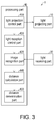
- FIG. 3 is a block diagram showing an example of the configuration of the optical distance measuring sensor 1 according to the embodiment of the disclosure.
- FIG. 3 details of the processing part 40 are shown, and the optical system 20 is omitted.
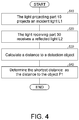
- FIG. 4 is a flowchart showing an example of the operation of the optical distance measuring sensor 1 according to the embodiment of the disclosure.
- the light projection control part 410 controls the light projecting part 10 to project the incident light L1 and instructs the light reception control part 420 to perform a process.
- the light projecting part 10 starts projecting the incident light L1 (step S10).
- the light reception control part 420 instructs the image recognition part 430 to receive light reception signals from the plurality of light receiving elements 31 of the light receiving part 30.
- the image recognition part 430 Upon being instructed by the light reception control part 420, the image recognition part 430 starts receiving light reception signals from the plurality of light receiving elements 31 of the light receiving part 30. After the light projecting part 10 starts projecting the incident light L1, the light receiving part 30 receives the reflected light L2 (step S20), and the image recognition part 430 receives the light reception signals from the plurality of light receiving elements 31 of the light receiving part 30.
- the image recognized by the image recognition part 430 receiving the light reception signals from the plurality of light receiving elements 31 of the light receiving part 30 is an image in which the pixels are arranged in a matrix of 8 ⁇ 8, as shown in (b) of Fig. 2 . That is, the image recognition part 430 recognizes the light reception signals from the plurality of light receiving elements 31 of the light receiving part 30 as a plurality of pixels. At this time, the light reception signals of the plurality of light receiving elements 31 correspond with the plurality of pixels in a one-to-one manner.
- the image recognition part 430 transmits the data of the recognized image to the distance calculation part 440.
- the distance calculation part 440 Upon receiving the image data from the image recognition part 430, the distance calculation part 440 calculates the distance between the light receiving part 30 and the detection object for all the pixels of the image recognized by the image recognition part 430 (step S30). In particular, the distance calculation part 440 calculates the distance for each pixel based on the received light amount of the light reception signal and the time difference between the time when the light projecting part 10 starts emitting the incident light L1 and the time when the image recognition part 430 receives the light reception signal. The distance calculation part 440 transmits the data of the calculated distances to the distance determination part 450.
- the distance determination part 450 determines that the shortest distance among the distances to the detection object calculated by the distance calculation part 440 is the distance to the object P1 (step S40). At this time, the object P1 is the detection object closest to the light receiving part 30. The result determined by the distance determination part 450 may be transmitted to the device provided with the optical distance measuring sensor 1.
- the optical distance measuring sensor 1 is adopted as a sensor for avoiding collision between the device provided with the optical distance measuring sensor 1 and the object P1, it is possible to accurately measure the distance to the object P1. Therefore, collision between the device provided with the optical distance measuring sensor 1 and the object P1 can be reliably avoided.
- the minimum value of a size D2 of the object PI which is measurable within the maximum measurement distance D1, as viewed from the light receiving part 30 is determined.
- the size D2 is the length in any direction of the object P1 as viewed from the light receiving part 30.
- the case where a minimum value Dmin of the size D2 of the object P1 is determined is taken into consideration.
- the optical system 20 is configured such that two or more light receiving elements 31 receive the reflected light from the object P1.
- the magnification ratio or reduction ratio of the convex lens of the optical system 20 and the position of the optical system 20 are determined such that the two or more light receiving elements 31 receive the reflected light from the object P1 having the size of the minimum value Dmin.
- the object P1 includes two or more pixels.
- the light receiving part 30, which receives the reflected light L2 from the object PI is a multi-pixel light receiving part having the plurality of light receiving elements 31. Therefore, for example, in the case where the processing part 40 calculates the distance to the detection object for each light reception signal of the plurality of light receiving elements 31, it is possible to determine that the shortest distance among the distances to the detection object is the distance to the object P1. Thus, compared with the case where the light receiving part 30 is not of a multi-pixel type and the distance to the object P1 is measured over the entire observation area, the distance to the object P1 can be accurately measured.
- the optical system 20 is configured such that two or more light receiving elements 31 among the plurality of light receiving elements 31 of the light receiving part 30 receive the reflected light from the object P1. Therefore, it is possible to accurately measure the distance to the object P1 without a measurement error due to the influence of the distance to the background, which occurs in the case of receiving the reflected light from the object with only one light receiving element.
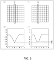
- FIG. 5 is a diagram showing an example of the case where an object P2 is arranged at the center of pixels arranged in any one column among a plurality of pixels when the object P2 includes one pixel among the plurality of pixels in the image recognized by the image recognition part 430.
- (b) of Fig. 5 is a diagram showing an example of the case where the object P2 is arranged at the boundary between any two columns of pixels among a plurality of pixels when the object P2 includes one pixel among the plurality of pixels in the image recognized by the image recognition part 430.
- "the object P2 including one pixel among the plurality of pixels" means that the width in the lateral direction of the object P2 is the same as or substantially the same as the width of one pixel.
- FIG. 5 is a view showing a measured distance of each pixel in the case of (a) of Fig. 5
- (d) of Fig. 5 is a view showing a measured distance of each pixel in the case of (b) of Fig. 5
- the horizontal axis corresponds to the column among the plurality of light receiving elements 31
- the vertical axis corresponds to the measured distance. For example, in the horizontal axis, if it is 1, it corresponds to the first column among the plurality of light receiving elements 31, and if it is 2, it corresponds to the second column among the plurality of light receiving elements 31. This also applies to (c) of Fig. 6 and (d) of Fig. 6 to be described later.
- the image recognition part 430 may not be able to accurately recognize the object P2.
- the object P2 is arranged at the boundary between any two columns of pixels among the plurality of pixels.
- the pixels adjacent to the boundary between the two columns include a part of the object P2. Therefore, a portion (background) other than the object P2 appears in these pixels.
- the measured distance M2 calculated with these pixels is a weighted average value of the distance based on the reflected light from the object P2 and the distance based on the reflected light from the background, the measured distance M2 does not match the actual distance between the light receiving part 30 and the object P2.
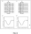
- FIG. 6 is a diagram showing an example of the case where an object P2 is arranged at the center of pixels arranged in any one column among a plurality of pixels when the object P2 includes two or more pixels among the plurality of pixels in the image recognized by the image recognition part 430.
- (b) of Fig. 6 is a diagram showing an example of the case where the object P2 is arranged at the boundary between any two columns of pixels among a plurality of pixels when the object P2 includes two or more pixels among the plurality of pixels in the image recognized by the image recognition part 430.
- "the object P2 including two or more pixels among the plurality of pixels" means that the width in the lateral direction of the object P2 is larger than the width of two pixels.
- FIG. 6 is a view showing a measured distance of each pixel in the case of (a) of Fig. 6
- (d) of Fig. 6 is a view showing a measured distance of each pixel in the case of (b) of Fig. 6 .
- two or more light receiving elements 31 among the plurality of light receiving elements 31 receive the reflected light from the object P2 such that the distance between the light receiving part 30 and the object P2 can be accurately measured.
- FIG. 7 is a schematic diagram showing the configuration of an optical distance measuring sensor 1a according to Modified Example 1 of the disclosure. As shown in FIG. 7 , the optical distance measuring sensor 1a is different from the optical distance measuring sensor 1 in that the optical system 20 is changed to an optical system 20a.
- the optical system 20a may include, for example, a zoom lens capable of changing the focal length.
- the optical system 20a includes a zoom lens, it is possible to change at least one of the maximum measurement distance D1 and the minimum value Dmin of the size D2 of the object P1 by changing the focal length. Therefore, it is possible to deal with various measurement environments and measurement objects.
- the zoom lens may be configured such that the focal length can be manually changed by a user or may be configured such that the focal length can be mechanically changed by a driving part included in the optical system 20a.
- FIG. 8 is a schematic diagram showing the configuration of an optical distance measuring sensor 1b according to Modified Example 2 of the disclosure. As shown in FIG. 8 , the optical distance measuring sensor 1b is different from the optical distance measuring sensor 1 in that the optical system 20 is changed to an optical system 20b.
- the optical system 20b may include, for example, a replacement mechanism configured to be capable of replacing at least one lens of the optical system 20b.
- the optical system 20b includes a replacement mechanism configured to be capable of replacing at least one lens of the optical system 20b. Therefore, by replacing the lens, at least one of the maximum measurement distance D1 and the minimum value Dmin of the size D2 of the object P1 can be changed. Thus, it is possible to deal with various measurement environments and measurement objects.
- the replacement mechanism may be configured such that at least one lens can be manually replaced by a user or may be configured such that at least one lens can be mechanically replaced by a driving part included in the optical system 20b.
- the control block (particularly the processing part 40) of the optical distance measuring sensor 1 may be realized by a logic circuit (hardware) formed in an integrated circuit (IC chip), etc. or may be realized by software.
- the optical distance measuring sensor 1 includes a computer that executes commands of a program, which is software for realizing each function.
- the computer includes, for example, one or more processors and includes a computer readable recording medium storing the program.
- the processor reads the program from the recording medium and executes the program, so as to achieve the disclosure.
- a CPU Central Processing Unit
- a non-transitory tangible medium such as a ROM (Read Only Memory), a tape, a disk, a card, a semiconductor memory, a programmable logic circuit, etc. may be used as the recording medium.
- a RAM Random Access Memory
- the above program may be provided to the computer via any transmission medium (e.g., a communication network, a broadcast wave, etc.) capable of transmitting the program.
- a transmission medium e.g., a communication network, a broadcast wave, etc.
- An embodiment of the disclosure can also be realized in the form of a data signal embedded in a carrier wave, in which the program is embodied by electronic transmission.
Landscapes
- Physics & Mathematics (AREA)
- Engineering & Computer Science (AREA)
- General Physics & Mathematics (AREA)
- Computer Networks & Wireless Communication (AREA)
- Radar, Positioning & Navigation (AREA)
- Remote Sensing (AREA)
- Electromagnetism (AREA)
- Optics & Photonics (AREA)
- Measurement Of Optical Distance (AREA)
- Optical Radar Systems And Details Thereof (AREA)
Abstract
Description
- The disclosure relates to an optical distance measuring sensor.
-
Patent Document 1 discloses a distance sensor including a light receiving device having a single-photon avalanche diode (SPAD) array divided into macro pixels, which is a distance sensor that monitors a danger area by using a protection area. - [Patent Document 1] Japanese Laid-open No.
2017-78707 (published on April 27, 2017 - However, the device disclosed in
Patent Document 1 has a problem that, for example, in the case where an object is present in the detection area, a measurement error may occur in the measurement of the distance to the object due to the influence of the distance to the background. - An objective of an embodiment of the disclosure is to accurately measure a distance to an object.
- In order to solve the above problem, the optical distance measuring sensor according to an embodiment of the disclosure is an optical distance measuring sensor that measures a distance to an object arranged in an area within a predetermined maximum measurement distance by projecting light to the object and receiving reflected light thereof. The optical distance measuring sensor includes a light receiving part including a plurality of light receiving elements and receiving the reflected light via an optical system. A minimum value of a size of the object, which is measurable within the maximum measurement distance, as viewed from the light receiving part is determined. The optical system is configured such that, in the case where the object having the size of the minimum value is arranged in the area within the maximum measurement distance, two or more of the light receiving elements receive the reflected light from the object.
- According to the above configuration, the light receiving part that receives the reflected light from the object is a multi-pixel light receiving part having a plurality of light receiving elements. Therefore, for example, in the case where the optical distance measuring sensor calculates the distance to a detection object for each light reception signal of the plurality of light receiving elements, a shortest distance among the distances to the detection object can be determined as the distance to the object. Therefore, compared with the case where the light receiving part is not of a multi-pixel type and the distance to the object is measured over the entire observation area, it is possible to accurately measure the distance to the object.
- Also, the optical system is configured such that two or more light receiving elements of the light receiving elements of the light receiving part receive the reflected light from the object. Therefore, it is possible to accurately measure the distance to the object without causing a measurement error due to the influence of the distance to the background, which occurs in the case of receiving the reflected light with only one light receiving element.
- In the optical distance measuring sensor according to an embodiment of the disclosure, the optical system preferably includes a zoom lens capable of changing a focal length.
- According to the above configuration, since the optical system includes the zoom lens, at least one of the maximum measurement distance and the minimum value of the size of the object can be changed by changing the focal length. Therefore, it is possible to deal with various measurement environments and measurement objects.
- In the optical distance measuring sensor according to an embodiment of the disclosure, the optical system preferably includes a replacement mechanism configured to be capable of replacing at least one lens of the optical system.
- According to the above configuration, the optical system includes a replacement mechanism configured to be capable of replacing at least one lens of the optical system. Therefore, by replacing the lens, at least one of the maximum measurement distance and the minimum value of the size of the object can be changed. Therefore, it is possible to deal with various measurement environments and measurement objects.
- It is preferable to further provide a processing part that performs a process of calculating a distance to a detection object for each light reception signal of the plurality of light receiving elements and determining that a shortest distance among the distances to the detection object is the distance to the object.
- According to the above configuration, compared with the case where the light receiving part is not of a multi-pixel type and the distance to the object is measured over the entire observation area, it is possible to accurately measure the distance to the object. In addition, in the case where the optical distance measuring sensor is adopted as the sensor for avoiding collision between a device provided with the optical distance measuring sensor and the object, it is possible to accurately measure the distance to the object. Therefore, collision between the device provided with the optical distance measuring sensor and the object can be reliably avoided.
- According to an embodiment of the disclosure, it is possible to accurately measure the distance to the object.
-
-
FIG. 1 is a schematic diagram showing an example of the configuration of an optical distance measuring sensor according to the embodiment of the disclosure. - (a) of
FIG. 2 is a schematic diagram showing an example of the configuration of a light receiving part, and (b) ofFIG. 2 is a diagram showing an example of an image recognized by the light receiving part. -
FIG. 3 is a block diagram showing an example of the configuration of the optical distance measuring sensor according to the embodiment of the disclosure. -
FIG. 4 is a flowchart showing an example of the operation of the optical distance measuring sensor according to the embodiment of the disclosure. - (a) of
Fig. 5 is a diagram showing an example of the case where an object is arranged at the center of pixels arranged in any one column among a plurality of pixels when the object includes one pixel among the plurality of pixels in the image recognized by an image recognition part. (b) ofFig. 5 is a diagram showing an example of the case where the object is arranged at the boundary between any two columns of pixels among a plurality of pixels when the object includes one pixel among the plurality of pixels in the image recognized by the image recognition part. (c) ofFig. 5 is a view showing a measured distance of each pixel in the case of (a) ofFig. 5 , and (d) ofFig. 5 is a view showing a measured distance of each pixel in the case of (b) ofFig. 5 . - (a) of
Fig. 6 is a diagram showing an example of the case where an object is arranged at the center of pixels arranged in any one column among a plurality of pixels when the object includes two or more pixels among the plurality of pixels in the image recognized by the image recognition part. (b) ofFig. 6 is a diagram showing an example of the case where the object is arranged at the boundary between any two columns of pixels among a plurality of pixels when the object includes two or more pixels among the plurality of pixels in the image recognized by the image recognition part. (c) ofFig. 6 is a view showing a measured distance of each pixel in the case of (a) ofFig. 6 , and (d) ofFig. 6 is a view showing a measured distance of each pixel in the case of (b) ofFig. 6 . -
FIG. 7 is a schematic diagram showing an example of the configuration of an optical distance measuring sensor according to Modified Example 1 of the disclosure. -
FIG. 8 is a schematic diagram showing an example of the configuration of an optical distance measuring sensor according to Modified Example 2 of the disclosure. - Hereinafter, an embodiment (hereinafter also referred to as "the present embodiment") according to an aspect of the disclosure will be described with reference to the drawings.
- First, referring to
FIG. 1 , an example of the scene to which the disclosure is applied will be described.FIG. 1 is a schematic view schematically showing an example of the application scene of an opticaldistance measuring sensor 1 according to the present embodiment and showing an example of the configuration of the opticaldistance measuring sensor 1 according to the embodiment of the disclosure. - As shown in
FIG. 1 , the opticaldistance measuring sensor 1 measures a distance to an object P1 arranged in an area within a predetermined maximum measurement distance D1 by projecting light to the object P1 and receiving the reflected light thereof. The opticaldistance measuring sensor 1 includes alight projecting part 10, anoptical system 20, alight receiving part 30, and aprocessing part 40. A small TOF (Time of Flight) distance measuring sensor that can operate even in a dark place and is used for a small camera, etc. may be adopted as the opticaldistance measuring sensor 1. Further, by adopting a small TOF distance measuring sensor as the opticaldistance measuring sensor 1, the cost for adopting the opticaldistance measuring sensor 1 can be reduced. - The
light projecting part 10 is, for example, a light projector that projects an incident light L1 to the object P1. Thelight projecting part 10 includes a light source (not shown) that emits light, a light projection optical fiber (not shown) that receives the light from the light source and guides the light to outside of the opticaldistance measuring sensor 1, and a light projection circuit (not shown) provided on a substrate (not shown). The light source may be, for example, an LED (light emitting diode). The light projection circuit may include an amplifier circuit. - The
optical system 20 may include, for example, a lens made of translucent glass or resin. Theoptical system 20 is arranged in the vicinity of thelight receiving part 30, and a convex lens may be adopted as the lens included in theoptical system 20. A reflected light L2 from a detection object such as the object P1 passes through theoptical system 20. - (a) of
Fig. 2 is a schematic diagram showing an example of the configuration of thelight receiving part 30, and (b) ofFig. 2 is a diagram showing an example of an image recognized by thelight receiving part 30. As shown in (a) ofFig. 2 , thelight receiving part 30 is a multi-pixel light receiving part having a plurality of light receivingelements 31 and receives the reflected light from the object P1 via theoptical system 20. Thelight receiving part 30 includes a light reception optical fiber (not shown) that receives the reflected light L2 and guides the reflected light L2 to the plurality of light receivingelements 31, and a light reception circuit (not shown) provided on asubstrate 32. For example, thelight receiving part 30 may have a structure in which the plurality of light receivingelements 31 are arranged in a matrix of m × n (m and n are natural numbers) on thesubstrate 32. In (a) ofFig. 2 , the plurality of light receivingelements 31 are arranged in a matrix of, for example, 8 × 8. - As shown in
FIG. 3 , theprocessing part 40 includes a lightprojection control part 410, a lightreception control part 420, animage recognition part 430, adistance calculation part 440, and adistance determination part 450. Theprocessing part 40 calculates the distance to the detection object for each light reception signal of the plurality of light receivingelements 31. In addition, in the case where the opticaldistance measuring sensor 1 is adopted as a sensor for avoiding collision between a device provided with the opticaldistance measuring sensor 1 and the object P1, theprocessing part 40 may, for example, perform a process for determining that the shortest distance among the distances to the detection object is the distance to the object P1. The details will be described below. - Next, the operation of the optical
distance measuring sensor 1 will be described with reference toFIG. 3 andFIG. 4 .FIG. 3 is a block diagram showing an example of the configuration of the opticaldistance measuring sensor 1 according to the embodiment of the disclosure. InFIG. 3 , details of theprocessing part 40 are shown, and theoptical system 20 is omitted.FIG. 4 is a flowchart showing an example of the operation of the opticaldistance measuring sensor 1 according to the embodiment of the disclosure. - First, the light
projection control part 410 controls thelight projecting part 10 to project the incident light L1 and instructs the lightreception control part 420 to perform a process. As a result, thelight projecting part 10 starts projecting the incident light L1 (step S10). Upon being instructed by the lightprojection control part 410 to perform a process, the lightreception control part 420 instructs theimage recognition part 430 to receive light reception signals from the plurality of light receivingelements 31 of thelight receiving part 30. - Upon being instructed by the light
reception control part 420, theimage recognition part 430 starts receiving light reception signals from the plurality of light receivingelements 31 of thelight receiving part 30. After thelight projecting part 10 starts projecting the incident light L1, thelight receiving part 30 receives the reflected light L2 (step S20), and theimage recognition part 430 receives the light reception signals from the plurality of light receivingelements 31 of thelight receiving part 30. - Here, in
FIG. 2A , the plurality of light receivingelements 31 are arranged in a matrix of 8 × 8. For this reason, the image recognized by theimage recognition part 430 receiving the light reception signals from the plurality of light receivingelements 31 of thelight receiving part 30 is an image in which the pixels are arranged in a matrix of 8 × 8, as shown in (b) ofFig. 2 . That is, theimage recognition part 430 recognizes the light reception signals from the plurality of light receivingelements 31 of thelight receiving part 30 as a plurality of pixels. At this time, the light reception signals of the plurality of light receivingelements 31 correspond with the plurality of pixels in a one-to-one manner. Theimage recognition part 430 transmits the data of the recognized image to thedistance calculation part 440. - Upon receiving the image data from the
image recognition part 430, thedistance calculation part 440 calculates the distance between the light receivingpart 30 and the detection object for all the pixels of the image recognized by the image recognition part 430 (step S30). In particular, thedistance calculation part 440 calculates the distance for each pixel based on the received light amount of the light reception signal and the time difference between the time when thelight projecting part 10 starts emitting the incident light L1 and the time when theimage recognition part 430 receives the light reception signal. Thedistance calculation part 440 transmits the data of the calculated distances to thedistance determination part 450. - Upon receiving the distance data from the
distance calculation part 440, thedistance determination part 450 determines that the shortest distance among the distances to the detection object calculated by thedistance calculation part 440 is the distance to the object P1 (step S40). At this time, the object P1 is the detection object closest to thelight receiving part 30. The result determined by thedistance determination part 450 may be transmitted to the device provided with the opticaldistance measuring sensor 1. - As described above, in the case where the optical
distance measuring sensor 1 is adopted as a sensor for avoiding collision between the device provided with the opticaldistance measuring sensor 1 and the object P1, it is possible to accurately measure the distance to the object P1. Therefore, collision between the device provided with the opticaldistance measuring sensor 1 and the object P1 can be reliably avoided. - In addition, as shown in
FIG. 1 , the minimum value of a size D2 of the object PI, which is measurable within the maximum measurement distance D1, as viewed from thelight receiving part 30 is determined. The size D2 is the length in any direction of the object P1 as viewed from thelight receiving part 30. Here, the case where a minimum value Dmin of the size D2 of the object P1 is determined is taken into consideration. In this case, when the object P1 having the size of the minimum value Dmin is arranged in the area within the maximum measurement distance D1, theoptical system 20 is configured such that two or morelight receiving elements 31 receive the reflected light from the object P1. - That is, at this time, for example, the magnification ratio or reduction ratio of the convex lens of the
optical system 20 and the position of theoptical system 20 are determined such that the two or morelight receiving elements 31 receive the reflected light from the object P1 having the size of the minimum value Dmin. In the case where the two or morelight receiving elements 31 receive the reflected light from the object P1 having the size of the minimum value Dmin, as shown in (b) ofFig. 2 , in the image recognized by theimage recognition part 430, the object P1 includes two or more pixels. - As described above, the
light receiving part 30, which receives the reflected light L2 from the object PI, is a multi-pixel light receiving part having the plurality of light receivingelements 31. Therefore, for example, in the case where theprocessing part 40 calculates the distance to the detection object for each light reception signal of the plurality of light receivingelements 31, it is possible to determine that the shortest distance among the distances to the detection object is the distance to the object P1. Thus, compared with the case where thelight receiving part 30 is not of a multi-pixel type and the distance to the object P1 is measured over the entire observation area, the distance to the object P1 can be accurately measured. - In addition, the
optical system 20 is configured such that two or morelight receiving elements 31 among the plurality of light receivingelements 31 of thelight receiving part 30 receive the reflected light from the object P1. Therefore, it is possible to accurately measure the distance to the object P1 without a measurement error due to the influence of the distance to the background, which occurs in the case of receiving the reflected light from the object with only one light receiving element. - (a) of
Fig. 5 is a diagram showing an example of the case where an object P2 is arranged at the center of pixels arranged in any one column among a plurality of pixels when the object P2 includes one pixel among the plurality of pixels in the image recognized by theimage recognition part 430. (b) ofFig. 5 is a diagram showing an example of the case where the object P2 is arranged at the boundary between any two columns of pixels among a plurality of pixels when the object P2 includes one pixel among the plurality of pixels in the image recognized by theimage recognition part 430. In (a) ofFig. 5 and (b) ofFig. 5 , "the object P2 including one pixel among the plurality of pixels" means that the width in the lateral direction of the object P2 is the same as or substantially the same as the width of one pixel. - (c) of
Fig. 5 is a view showing a measured distance of each pixel in the case of (a) ofFig. 5 , and (d) ofFig. 5 is a view showing a measured distance of each pixel in the case of (b) ofFig. 5 . In (c) ofFig. 5 and (d) ofFig. 5 , the horizontal axis corresponds to the column among the plurality of light receivingelements 31, and the vertical axis corresponds to the measured distance. For example, in the horizontal axis, if it is 1, it corresponds to the first column among the plurality of light receivingelements 31, and if it is 2, it corresponds to the second column among the plurality of light receivingelements 31. This also applies to (c) ofFig. 6 and (d) ofFig. 6 to be described later. - In (c) of
Fig. 5 , in the image recognized by theimage recognition part 430, in the case where the object P2 includes one pixel among the plurality of pixels, a measured distance M1 between the light receivingpart 30 and the object P2 matches the actual distance between the light receivingpart 30 and the object P2. However, in (d) ofFig. 5 , in the image recognized by theimage recognition part 430, in the case where the object P2 includes one pixel among the plurality of pixels, a measured distance M2 between the light receivingpart 30 and the object P2 does not match the actual distance between the light receivingpart 30 and the object P2. The reasons are as described below. In the case where the object P2 includes one pixel among the plurality of pixels, depending on the position of the object P2, theimage recognition part 430 may not be able to accurately recognize the object P2. For example, as shown in (b) ofFig. 5 , there is a case where the object P2 is arranged at the boundary between any two columns of pixels among the plurality of pixels. In this case, since the object P2 is arranged at the boundary between the two columns, the pixels adjacent to the boundary between the two columns include a part of the object P2. Therefore, a portion (background) other than the object P2 appears in these pixels. As a result, since the measured distance M2 calculated with these pixels is a weighted average value of the distance based on the reflected light from the object P2 and the distance based on the reflected light from the background, the measured distance M2 does not match the actual distance between the light receivingpart 30 and the object P2. - (a) of
Fig. 6 is a diagram showing an example of the case where an object P2 is arranged at the center of pixels arranged in any one column among a plurality of pixels when the object P2 includes two or more pixels among the plurality of pixels in the image recognized by theimage recognition part 430. (b) ofFig. 6 is a diagram showing an example of the case where the object P2 is arranged at the boundary between any two columns of pixels among a plurality of pixels when the object P2 includes two or more pixels among the plurality of pixels in the image recognized by theimage recognition part 430. In (a) ofFig. 6 and (b) ofFig. 6 , "the object P2 including two or more pixels among the plurality of pixels" means that the width in the lateral direction of the object P2 is larger than the width of two pixels. - (c) of
Fig. 6 is a view showing a measured distance of each pixel in the case of (a) ofFig. 6 , and (d) ofFig. 6 is a view showing a measured distance of each pixel in the case of (b) ofFig. 6 . - In (c) of
Fig. 6 and (d) ofFig. 6 , in the image recognized by theimage recognition part 430, in the case where the object P2 includes two or more pixels among the plurality of pixels, a measured distance M1 between the light receivingpart 30 and the object P2 matches the actual distance between the light receivingpart 30 and the object P2. - As described above, even in the case where the object P2 is arranged at the boundary between any two columns of pixels among the plurality of pixels, two or more
light receiving elements 31 among the plurality of light receivingelements 31 receive the reflected light from the object P2 such that the distance between the light receivingpart 30 and the object P2 can be accurately measured. -
FIG. 7 is a schematic diagram showing the configuration of an optical distance measuring sensor 1a according to Modified Example 1 of the disclosure. As shown inFIG. 7 , the optical distance measuring sensor 1a is different from the opticaldistance measuring sensor 1 in that theoptical system 20 is changed to anoptical system 20a. Theoptical system 20a may include, for example, a zoom lens capable of changing the focal length. - In this way, since the
optical system 20a includes a zoom lens, it is possible to change at least one of the maximum measurement distance D1 and the minimum value Dmin of the size D2 of the object P1 by changing the focal length. Therefore, it is possible to deal with various measurement environments and measurement objects. - The zoom lens may be configured such that the focal length can be manually changed by a user or may be configured such that the focal length can be mechanically changed by a driving part included in the
optical system 20a. -
FIG. 8 is a schematic diagram showing the configuration of an opticaldistance measuring sensor 1b according to Modified Example 2 of the disclosure. As shown inFIG. 8 , the opticaldistance measuring sensor 1b is different from the opticaldistance measuring sensor 1 in that theoptical system 20 is changed to anoptical system 20b. Theoptical system 20b may include, for example, a replacement mechanism configured to be capable of replacing at least one lens of theoptical system 20b. - In this way, the
optical system 20b includes a replacement mechanism configured to be capable of replacing at least one lens of theoptical system 20b. Therefore, by replacing the lens, at least one of the maximum measurement distance D1 and the minimum value Dmin of the size D2 of the object P1 can be changed. Thus, it is possible to deal with various measurement environments and measurement objects. - The replacement mechanism may be configured such that at least one lens can be manually replaced by a user or may be configured such that at least one lens can be mechanically replaced by a driving part included in the
optical system 20b. - The control block (particularly the processing part 40) of the optical
distance measuring sensor 1 may be realized by a logic circuit (hardware) formed in an integrated circuit (IC chip), etc. or may be realized by software. - In the latter case, the optical
distance measuring sensor 1 includes a computer that executes commands of a program, which is software for realizing each function. The computer includes, for example, one or more processors and includes a computer readable recording medium storing the program. In the computer, the processor reads the program from the recording medium and executes the program, so as to achieve the disclosure. For example, a CPU (Central Processing Unit) may be used as the processor. In addition to a "non-transitory tangible medium" such as a ROM (Read Only Memory), a tape, a disk, a card, a semiconductor memory, a programmable logic circuit, etc. may be used as the recording medium. Further, a RAM (Random Access Memory), etc. may be further included for developing the above program. In addition, the above program may be provided to the computer via any transmission medium (e.g., a communication network, a broadcast wave, etc.) capable of transmitting the program. An embodiment of the disclosure can also be realized in the form of a data signal embedded in a carrier wave, in which the program is embodied by electronic transmission. -
- 1, 1a, and 1b
- optical distance measuring sensor
- 10
- light projecting part
- 20, 20a, and 20b
- optical system
- 30
- light receiving part
- 31
- light receiving element
- 32
- substrate
- 40
- processing part
- 410
- light projection control part
- 420
- light reception control part
- 430
- image recognition part
- 440
- distance calculation part
- 450
- distance determination part
- D1
- maximum measurement distance
- Dmin
- minimum value
- L1
- incident light
- L2
- reflected light
- M1 and M2
- measured distance
- P1 and P2
- object
Claims (4)
- An optical distance measuring sensor (1, 1a, 1b) that measures a distance to an object (P1, P2) arranged in an area within a predetermined maximum measurement distance by projecting light to the object (P1, P2) and receiving reflected light thereof, the optical distance measuring sensor (1, 1a, 1b) characterized in comprising:a light receiving part (30) comprising a plurality of light receiving elements (31) and receiving the reflected light via an optical system (20, 20a, 20b), whereina minimum value of a size of the object (P1, P2), which is measurable within the maximum measurement distance, as viewed from the light receiving part (30) is determined, andthe optical system (20, 20a, 20b) is configured such that, in the case where the object (P1, P2) having the size of the minimum value is arranged in the area within the maximum measurement distance, two or more of the light receiving elements (31) receive the reflected light from the object (P1, P2).
- The optical distance measuring sensor (1, 1a, 1b) according to claim 1, wherein the optical system (20, 20a, 20b) comprises a zoom lens capable of changing a focal length.
- The optical distance measuring sensor (1, 1a, 1b) according to claim 1, wherein the optical system (20, 20a, 20b) comprises a replacement mechanism configured to be capable of replacing at least one lens of the optical system (20, 20a, 20b).
- The optical distance measuring sensor (1, 1a, 1b) according to any one of claims 1 to 3, further comprising a processing part (40) that performs a process of calculating a distance to a detection object (P1, P2) for each light reception signal of the plurality of light receiving elements (31) and determining that a shortest distance among the distances to the detection object (P1, P2) is the distance to the object (P1, P2).
Applications Claiming Priority (1)
| Application Number | Priority Date | Filing Date | Title |
|---|---|---|---|
| JP2018039803A JP2019152616A (en) | 2018-03-06 | 2018-03-06 | Optical distance measuring sensor |
Publications (2)
| Publication Number | Publication Date |
|---|---|
| EP3537178A1 true EP3537178A1 (en) | 2019-09-11 |
| EP3537178B1 EP3537178B1 (en) | 2023-04-19 |
Family
ID=64665444
Family Applications (1)
| Application Number | Title | Priority Date | Filing Date |
|---|---|---|---|
| EP18212351.3A Active EP3537178B1 (en) | 2018-03-06 | 2018-12-13 | Optical distance measuring sensor |
Country Status (6)
| Country | Link |
|---|---|
| US (1) | US20190277948A1 (en) |
| EP (1) | EP3537178B1 (en) |
| JP (1) | JP2019152616A (en) |
| KR (1) | KR102177993B1 (en) |
| CN (1) | CN110231629A (en) |
| TW (1) | TWI695179B (en) |
Families Citing this family (3)
| Publication number | Priority date | Publication date | Assignee | Title |
|---|---|---|---|---|
| US11560153B2 (en) * | 2019-03-07 | 2023-01-24 | 6 River Systems, Llc | Systems and methods for collision avoidance by autonomous vehicles |
| WO2022064576A1 (en) | 2020-09-23 | 2022-03-31 | 株式会社ソニー・インタラクティブエンタテインメント | Position information acquisition device, head-mounted display, and position information acquisition method |
| WO2022064583A1 (en) | 2020-09-24 | 2022-03-31 | 株式会社ソニー・インタラクティブエンタテインメント | Distance information generation device and distance information generation method |
Citations (3)
| Publication number | Priority date | Publication date | Assignee | Title |
|---|---|---|---|---|
| EP1845334A1 (en) * | 2006-04-11 | 2007-10-17 | Leuze electronic GmbH + Co. KG | Optical sensor |
| US20150108376A1 (en) * | 2013-10-18 | 2015-04-23 | Keyence Corporation | Distance Measuring Photoelectric Sensor And Method For Controlling Light Projection Spot Thereof |
| JP2017078707A (en) | 2015-07-31 | 2017-04-27 | ジック アーゲー | Distance sensor |
Family Cites Families (14)
| Publication number | Priority date | Publication date | Assignee | Title |
|---|---|---|---|---|
| DE1139736B (en) * | 1960-09-07 | 1962-11-15 | Zeiss Ikon Ag | Device for image recording or playback |
| DE1278755B (en) * | 1967-01-26 | 1968-09-26 | Leitz Ernst Gmbh | Stereo microscope |
| KR100620910B1 (en) * | 2004-03-08 | 2006-09-13 | 엠텍비젼 주식회사 | Mobile phones with cameras with interchangeable lenses |
| JPWO2009031550A1 (en) * | 2007-09-05 | 2010-12-16 | 株式会社 ニコンビジョン | Ranging device |
| JP2010164440A (en) * | 2009-01-16 | 2010-07-29 | Stanley Electric Co Ltd | Distance image processing device and photographing device |
| JP5116754B2 (en) * | 2009-12-10 | 2013-01-09 | シャープ株式会社 | Optical detection device and electronic apparatus |
| DE102011076491A1 (en) * | 2011-05-26 | 2012-11-29 | Esw Gmbh | Measuring device for distance measurement |
| KR20130102400A (en) * | 2012-03-07 | 2013-09-17 | 삼성전자주식회사 | Time of flight sensor and time of flight camera |
| US9689987B1 (en) * | 2012-06-13 | 2017-06-27 | Physical Optics Corporation | Integrative optics system, device, and method |
| JP2014157044A (en) * | 2013-02-15 | 2014-08-28 | Canon Inc | Distance detection camera |
| EP2865596B1 (en) * | 2013-10-23 | 2018-03-28 | Airbus Operations GmbH | Automatic transportation arrangement for cargo loading system |
| US11243294B2 (en) * | 2014-05-19 | 2022-02-08 | Rockwell Automation Technologies, Inc. | Waveform reconstruction in a time-of-flight sensor |
| JP6597150B2 (en) * | 2015-10-09 | 2019-10-30 | 富士通株式会社 | Distance measuring device, distance measuring method, distance measuring program, and table creation method |
| US10557943B2 (en) * | 2016-08-22 | 2020-02-11 | Apple Inc. | Optical systems |
-
2018
- 2018-03-06 JP JP2018039803A patent/JP2019152616A/en active Pending
- 2018-12-11 KR KR1020180158814A patent/KR102177993B1/en active Active
- 2018-12-11 TW TW107144614A patent/TWI695179B/en active
- 2018-12-12 CN CN201811516144.7A patent/CN110231629A/en active Pending
- 2018-12-13 EP EP18212351.3A patent/EP3537178B1/en active Active
- 2018-12-14 US US16/219,959 patent/US20190277948A1/en not_active Abandoned
Patent Citations (3)
| Publication number | Priority date | Publication date | Assignee | Title |
|---|---|---|---|---|
| EP1845334A1 (en) * | 2006-04-11 | 2007-10-17 | Leuze electronic GmbH + Co. KG | Optical sensor |
| US20150108376A1 (en) * | 2013-10-18 | 2015-04-23 | Keyence Corporation | Distance Measuring Photoelectric Sensor And Method For Controlling Light Projection Spot Thereof |
| JP2017078707A (en) | 2015-07-31 | 2017-04-27 | ジック アーゲー | Distance sensor |
Non-Patent Citations (1)
| Title |
|---|
| OLLIKKALA A V H ET AL: "Range imaging using a time-of-flight 3D camera and a cooperative object", 2009 IEEE INTRUMENTATION AND MEASUREMENT TECHNOLOGY CONFERENCE (I2MTC) - 5-7 MAY 2009 - SINGAPORE, SINGAPORE, IEEE, PISCATAWAY, NJ, USA, 5 May 2009 (2009-05-05), pages 817 - 821, XP031492748, ISBN: 978-1-4244-3352-0 * |
Also Published As
| Publication number | Publication date |
|---|---|
| TW201939064A (en) | 2019-10-01 |
| US20190277948A1 (en) | 2019-09-12 |
| KR20190106649A (en) | 2019-09-18 |
| CN110231629A (en) | 2019-09-13 |
| TWI695179B (en) | 2020-06-01 |
| EP3537178B1 (en) | 2023-04-19 |
| KR102177993B1 (en) | 2020-11-12 |
| JP2019152616A (en) | 2019-09-12 |
Similar Documents
| Publication | Publication Date | Title |
|---|---|---|
| KR101033428B1 (en) | Position detection device using area image sensor | |
| US8390793B2 (en) | Optical ranging sensor and electronic equipment | |
| US20200195875A1 (en) | Dynamically programmable image sensor | |
| CN112204420B (en) | Time-of-flight rangefinder for structured light systems | |
| US11906353B2 (en) | Digital pixel with extended dynamic range | |
| EP3537178B1 (en) | Optical distance measuring sensor | |
| KR102691741B1 (en) | Methods and apparatus for using range data to predict object features | |
| US9759549B2 (en) | Distance detecting device | |
| KR20220023979A (en) | Position detection system, image processing device, position detection method and position detection program | |
| US9158183B2 (en) | Stereoscopic image generating device and stereoscopic image generating method | |
| US20200092464A1 (en) | Electronic device and notification method | |
| US11940568B2 (en) | Enhanced multispectral sensor calibration | |
| JP7275941B2 (en) | 3D information acquisition device and 3D information acquisition method | |
| US20170363723A1 (en) | Optical calibration system adapted for optical distance measurement system | |
| US10215628B2 (en) | Image calibrating method and device of testing apparatus for thin film transistor substrate | |
| EP3832273A1 (en) | Electromagnetic wave detection device and information acquisition system | |
| US6791617B1 (en) | Distance detecting device and a method for distance detection | |
| US11493332B1 (en) | Three-dimensional sensing system for determining three-dimensional profile of object and method thereof | |
| US12424070B2 (en) | Smoke detector and optical sensing system | |
| US20250072145A1 (en) | Optical sensing system and light gating layer | |
| EP3637044B1 (en) | Multi-image projector and electronic device having the multi-image projector | |
| JP2015232495A (en) | Optical characteristic measurement device | |
| US20250219729A1 (en) | Free space optical communication system, management apparatus, and free space optical communication apparatus | |
| JP4229964B2 (en) | Position detection device using area image sensor | |
| EP4261610A1 (en) | Electromagnetic wave detection device and electromagnetic wave detection method |
Legal Events
| Date | Code | Title | Description |
|---|---|---|---|
| PUAI | Public reference made under article 153(3) epc to a published international application that has entered the european phase |
Free format text: ORIGINAL CODE: 0009012 |
|
| STAA | Information on the status of an ep patent application or granted ep patent |
Free format text: STATUS: REQUEST FOR EXAMINATION WAS MADE |
|
| 17P | Request for examination filed |
Effective date: 20181213 |
|
| AK | Designated contracting states |
Kind code of ref document: A1 Designated state(s): AL AT BE BG CH CY CZ DE DK EE ES FI FR GB GR HR HU IE IS IT LI LT LU LV MC MK MT NL NO PL PT RO RS SE SI SK SM TR |
|
| AX | Request for extension of the european patent |
Extension state: BA ME |
|
| RBV | Designated contracting states (corrected) |
Designated state(s): AL AT BE BG CH CY CZ DE DK EE ES FI FR GB GR HR HU IE IS IT LI LT LU LV MC MK MT NL NO PL PT RO RS SE SI SK SM TR |
|
| STAA | Information on the status of an ep patent application or granted ep patent |
Free format text: STATUS: EXAMINATION IS IN PROGRESS |
|
| 17Q | First examination report despatched |
Effective date: 20211005 |
|
| REG | Reference to a national code |
Ref country code: DE Ref legal event code: R079 Ref document number: 602018048528 Country of ref document: DE Free format text: PREVIOUS MAIN CLASS: G01S0017890000 Ipc: G01S0017894000 |
|
| RIC1 | Information provided on ipc code assigned before grant |
Ipc: G01S 7/497 20060101ALI20221111BHEP Ipc: G01S 17/93 20060101ALI20221111BHEP Ipc: G01S 7/481 20060101ALI20221111BHEP Ipc: G01S 17/894 20200101AFI20221111BHEP |
|
| GRAP | Despatch of communication of intention to grant a patent |
Free format text: ORIGINAL CODE: EPIDOSNIGR1 |
|
| STAA | Information on the status of an ep patent application or granted ep patent |
Free format text: STATUS: GRANT OF PATENT IS INTENDED |
|
| INTG | Intention to grant announced |
Effective date: 20230104 |
|
| GRAS | Grant fee paid |
Free format text: ORIGINAL CODE: EPIDOSNIGR3 |
|
| GRAA | (expected) grant |
Free format text: ORIGINAL CODE: 0009210 |
|
| STAA | Information on the status of an ep patent application or granted ep patent |
Free format text: STATUS: THE PATENT HAS BEEN GRANTED |
|
| REG | Reference to a national code |
Ref country code: DE Ref legal event code: R081 Ref document number: 602018048528 Country of ref document: DE Owner name: OMRON CORPORATION, JP Free format text: FORMER OWNER: OMRON CORPORATION, KYOTO-SHI, KYOTO, JP |
|
| AK | Designated contracting states |
Kind code of ref document: B1 Designated state(s): AL AT BE BG CH CY CZ DE DK EE ES FI FR GB GR HR HU IE IS IT LI LT LU LV MC MK MT NL NO PL PT RO RS SE SI SK SM TR |
|
| REG | Reference to a national code |
Ref country code: GB Ref legal event code: FG4D |
|
| REG | Reference to a national code |
Ref country code: DE Ref legal event code: R096 Ref document number: 602018048528 Country of ref document: DE |
|
| REG | Reference to a national code |
Ref country code: CH Ref legal event code: EP |
|
| REG | Reference to a national code |
Ref country code: IE Ref legal event code: FG4D |
|
| REG | Reference to a national code |
Ref country code: AT Ref legal event code: REF Ref document number: 1561604 Country of ref document: AT Kind code of ref document: T Effective date: 20230515 |
|
| REG | Reference to a national code |
Ref country code: LT Ref legal event code: MG9D |
|
| REG | Reference to a national code |
Ref country code: NL Ref legal event code: MP Effective date: 20230419 |
|
| REG | Reference to a national code |
Ref country code: AT Ref legal event code: MK05 Ref document number: 1561604 Country of ref document: AT Kind code of ref document: T Effective date: 20230419 |
|
| PG25 | Lapsed in a contracting state [announced via postgrant information from national office to epo] |
Ref country code: NL Free format text: LAPSE BECAUSE OF FAILURE TO SUBMIT A TRANSLATION OF THE DESCRIPTION OR TO PAY THE FEE WITHIN THE PRESCRIBED TIME-LIMIT Effective date: 20230419 |
|
| PG25 | Lapsed in a contracting state [announced via postgrant information from national office to epo] |
Ref country code: SE Free format text: LAPSE BECAUSE OF FAILURE TO SUBMIT A TRANSLATION OF THE DESCRIPTION OR TO PAY THE FEE WITHIN THE PRESCRIBED TIME-LIMIT Effective date: 20230419 Ref country code: PT Free format text: LAPSE BECAUSE OF FAILURE TO SUBMIT A TRANSLATION OF THE DESCRIPTION OR TO PAY THE FEE WITHIN THE PRESCRIBED TIME-LIMIT Effective date: 20230821 Ref country code: NO Free format text: LAPSE BECAUSE OF FAILURE TO SUBMIT A TRANSLATION OF THE DESCRIPTION OR TO PAY THE FEE WITHIN THE PRESCRIBED TIME-LIMIT Effective date: 20230719 Ref country code: ES Free format text: LAPSE BECAUSE OF FAILURE TO SUBMIT A TRANSLATION OF THE DESCRIPTION OR TO PAY THE FEE WITHIN THE PRESCRIBED TIME-LIMIT Effective date: 20230419 Ref country code: AT Free format text: LAPSE BECAUSE OF FAILURE TO SUBMIT A TRANSLATION OF THE DESCRIPTION OR TO PAY THE FEE WITHIN THE PRESCRIBED TIME-LIMIT Effective date: 20230419 |
|
| PG25 | Lapsed in a contracting state [announced via postgrant information from national office to epo] |
Ref country code: RS Free format text: LAPSE BECAUSE OF FAILURE TO SUBMIT A TRANSLATION OF THE DESCRIPTION OR TO PAY THE FEE WITHIN THE PRESCRIBED TIME-LIMIT Effective date: 20230419 Ref country code: PL Free format text: LAPSE BECAUSE OF FAILURE TO SUBMIT A TRANSLATION OF THE DESCRIPTION OR TO PAY THE FEE WITHIN THE PRESCRIBED TIME-LIMIT Effective date: 20230419 Ref country code: LV Free format text: LAPSE BECAUSE OF FAILURE TO SUBMIT A TRANSLATION OF THE DESCRIPTION OR TO PAY THE FEE WITHIN THE PRESCRIBED TIME-LIMIT Effective date: 20230419 Ref country code: LT Free format text: LAPSE BECAUSE OF FAILURE TO SUBMIT A TRANSLATION OF THE DESCRIPTION OR TO PAY THE FEE WITHIN THE PRESCRIBED TIME-LIMIT Effective date: 20230419 Ref country code: IS Free format text: LAPSE BECAUSE OF FAILURE TO SUBMIT A TRANSLATION OF THE DESCRIPTION OR TO PAY THE FEE WITHIN THE PRESCRIBED TIME-LIMIT Effective date: 20230819 Ref country code: HR Free format text: LAPSE BECAUSE OF FAILURE TO SUBMIT A TRANSLATION OF THE DESCRIPTION OR TO PAY THE FEE WITHIN THE PRESCRIBED TIME-LIMIT Effective date: 20230419 Ref country code: GR Free format text: LAPSE BECAUSE OF FAILURE TO SUBMIT A TRANSLATION OF THE DESCRIPTION OR TO PAY THE FEE WITHIN THE PRESCRIBED TIME-LIMIT Effective date: 20230720 Ref country code: AL Free format text: LAPSE BECAUSE OF FAILURE TO SUBMIT A TRANSLATION OF THE DESCRIPTION OR TO PAY THE FEE WITHIN THE PRESCRIBED TIME-LIMIT Effective date: 20230419 |
|
| PG25 | Lapsed in a contracting state [announced via postgrant information from national office to epo] |
Ref country code: FI Free format text: LAPSE BECAUSE OF FAILURE TO SUBMIT A TRANSLATION OF THE DESCRIPTION OR TO PAY THE FEE WITHIN THE PRESCRIBED TIME-LIMIT Effective date: 20230419 |
|
| PG25 | Lapsed in a contracting state [announced via postgrant information from national office to epo] |
Ref country code: SK Free format text: LAPSE BECAUSE OF FAILURE TO SUBMIT A TRANSLATION OF THE DESCRIPTION OR TO PAY THE FEE WITHIN THE PRESCRIBED TIME-LIMIT Effective date: 20230419 |
|
| REG | Reference to a national code |
Ref country code: DE Ref legal event code: R097 Ref document number: 602018048528 Country of ref document: DE |
|
| PG25 | Lapsed in a contracting state [announced via postgrant information from national office to epo] |
Ref country code: SM Free format text: LAPSE BECAUSE OF FAILURE TO SUBMIT A TRANSLATION OF THE DESCRIPTION OR TO PAY THE FEE WITHIN THE PRESCRIBED TIME-LIMIT Effective date: 20230419 Ref country code: SK Free format text: LAPSE BECAUSE OF FAILURE TO SUBMIT A TRANSLATION OF THE DESCRIPTION OR TO PAY THE FEE WITHIN THE PRESCRIBED TIME-LIMIT Effective date: 20230419 Ref country code: RO Free format text: LAPSE BECAUSE OF FAILURE TO SUBMIT A TRANSLATION OF THE DESCRIPTION OR TO PAY THE FEE WITHIN THE PRESCRIBED TIME-LIMIT Effective date: 20230419 Ref country code: EE Free format text: LAPSE BECAUSE OF FAILURE TO SUBMIT A TRANSLATION OF THE DESCRIPTION OR TO PAY THE FEE WITHIN THE PRESCRIBED TIME-LIMIT Effective date: 20230419 Ref country code: DK Free format text: LAPSE BECAUSE OF FAILURE TO SUBMIT A TRANSLATION OF THE DESCRIPTION OR TO PAY THE FEE WITHIN THE PRESCRIBED TIME-LIMIT Effective date: 20230419 Ref country code: CZ Free format text: LAPSE BECAUSE OF FAILURE TO SUBMIT A TRANSLATION OF THE DESCRIPTION OR TO PAY THE FEE WITHIN THE PRESCRIBED TIME-LIMIT Effective date: 20230419 |
|
| PLBE | No opposition filed within time limit |
Free format text: ORIGINAL CODE: 0009261 |
|
| STAA | Information on the status of an ep patent application or granted ep patent |
Free format text: STATUS: NO OPPOSITION FILED WITHIN TIME LIMIT |
|
| 26N | No opposition filed |
Effective date: 20240122 |
|
| PG25 | Lapsed in a contracting state [announced via postgrant information from national office to epo] |
Ref country code: SI Free format text: LAPSE BECAUSE OF FAILURE TO SUBMIT A TRANSLATION OF THE DESCRIPTION OR TO PAY THE FEE WITHIN THE PRESCRIBED TIME-LIMIT Effective date: 20230419 |
|
| PG25 | Lapsed in a contracting state [announced via postgrant information from national office to epo] |
Ref country code: SI Free format text: LAPSE BECAUSE OF FAILURE TO SUBMIT A TRANSLATION OF THE DESCRIPTION OR TO PAY THE FEE WITHIN THE PRESCRIBED TIME-LIMIT Effective date: 20230419 Ref country code: IT Free format text: LAPSE BECAUSE OF FAILURE TO SUBMIT A TRANSLATION OF THE DESCRIPTION OR TO PAY THE FEE WITHIN THE PRESCRIBED TIME-LIMIT Effective date: 20230419 |
|
| REG | Reference to a national code |
Ref country code: CH Ref legal event code: PL |
|
| PG25 | Lapsed in a contracting state [announced via postgrant information from national office to epo] |
Ref country code: LU Free format text: LAPSE BECAUSE OF NON-PAYMENT OF DUE FEES Effective date: 20231213 |
|
| PG25 | Lapsed in a contracting state [announced via postgrant information from national office to epo] |
Ref country code: MC Free format text: LAPSE BECAUSE OF FAILURE TO SUBMIT A TRANSLATION OF THE DESCRIPTION OR TO PAY THE FEE WITHIN THE PRESCRIBED TIME-LIMIT Effective date: 20230419 |
|
| GBPC | Gb: european patent ceased through non-payment of renewal fee |
Effective date: 20231213 |
|
| REG | Reference to a national code |
Ref country code: BE Ref legal event code: MM Effective date: 20231231 |
|
| PG25 | Lapsed in a contracting state [announced via postgrant information from national office to epo] |
Ref country code: MC Free format text: LAPSE BECAUSE OF FAILURE TO SUBMIT A TRANSLATION OF THE DESCRIPTION OR TO PAY THE FEE WITHIN THE PRESCRIBED TIME-LIMIT Effective date: 20230419 Ref country code: LU Free format text: LAPSE BECAUSE OF NON-PAYMENT OF DUE FEES Effective date: 20231213 |
|
| REG | Reference to a national code |
Ref country code: IE Ref legal event code: MM4A |
|
| PG25 | Lapsed in a contracting state [announced via postgrant information from national office to epo] |
Ref country code: IE Free format text: LAPSE BECAUSE OF NON-PAYMENT OF DUE FEES Effective date: 20231213 |
|
| PG25 | Lapsed in a contracting state [announced via postgrant information from national office to epo] |
Ref country code: GB Free format text: LAPSE BECAUSE OF NON-PAYMENT OF DUE FEES Effective date: 20231213 |
|
| PG25 | Lapsed in a contracting state [announced via postgrant information from national office to epo] |
Ref country code: BE Free format text: LAPSE BECAUSE OF NON-PAYMENT OF DUE FEES Effective date: 20231231 |
|
| PG25 | Lapsed in a contracting state [announced via postgrant information from national office to epo] |
Ref country code: FR Free format text: LAPSE BECAUSE OF NON-PAYMENT OF DUE FEES Effective date: 20231231 |
|
| PG25 | Lapsed in a contracting state [announced via postgrant information from national office to epo] |
Ref country code: CH Free format text: LAPSE BECAUSE OF NON-PAYMENT OF DUE FEES Effective date: 20231231 |
|
| PG25 | Lapsed in a contracting state [announced via postgrant information from national office to epo] |
Ref country code: IE Free format text: LAPSE BECAUSE OF NON-PAYMENT OF DUE FEES Effective date: 20231213 Ref country code: GB Free format text: LAPSE BECAUSE OF NON-PAYMENT OF DUE FEES Effective date: 20231213 Ref country code: FR Free format text: LAPSE BECAUSE OF NON-PAYMENT OF DUE FEES Effective date: 20231231 Ref country code: CH Free format text: LAPSE BECAUSE OF NON-PAYMENT OF DUE FEES Effective date: 20231231 Ref country code: BE Free format text: LAPSE BECAUSE OF NON-PAYMENT OF DUE FEES Effective date: 20231231 |
|
| PG25 | Lapsed in a contracting state [announced via postgrant information from national office to epo] |
Ref country code: BG Free format text: LAPSE BECAUSE OF FAILURE TO SUBMIT A TRANSLATION OF THE DESCRIPTION OR TO PAY THE FEE WITHIN THE PRESCRIBED TIME-LIMIT Effective date: 20230419 |
|
| PG25 | Lapsed in a contracting state [announced via postgrant information from national office to epo] |
Ref country code: BG Free format text: LAPSE BECAUSE OF FAILURE TO SUBMIT A TRANSLATION OF THE DESCRIPTION OR TO PAY THE FEE WITHIN THE PRESCRIBED TIME-LIMIT Effective date: 20230419 |
|
| PG25 | Lapsed in a contracting state [announced via postgrant information from national office to epo] |
Ref country code: CY Free format text: LAPSE BECAUSE OF FAILURE TO SUBMIT A TRANSLATION OF THE DESCRIPTION OR TO PAY THE FEE WITHIN THE PRESCRIBED TIME-LIMIT; INVALID AB INITIO Effective date: 20181213 |
|
| PG25 | Lapsed in a contracting state [announced via postgrant information from national office to epo] |
Ref country code: HU Free format text: LAPSE BECAUSE OF FAILURE TO SUBMIT A TRANSLATION OF THE DESCRIPTION OR TO PAY THE FEE WITHIN THE PRESCRIBED TIME-LIMIT; INVALID AB INITIO Effective date: 20181213 |
|
| PG25 | Lapsed in a contracting state [announced via postgrant information from national office to epo] |
Ref country code: TR Free format text: LAPSE BECAUSE OF FAILURE TO SUBMIT A TRANSLATION OF THE DESCRIPTION OR TO PAY THE FEE WITHIN THE PRESCRIBED TIME-LIMIT Effective date: 20230419 |
|
| PGFP | Annual fee paid to national office [announced via postgrant information from national office to epo] |
Ref country code: DE Payment date: 20251222 Year of fee payment: 8 |