EP3537172A1 - Empfangsanordnung zum empfang von lichtsignalen und verfahren zum empfangen von lichtsignalen - Google Patents
Empfangsanordnung zum empfang von lichtsignalen und verfahren zum empfangen von lichtsignalen Download PDFInfo
- Publication number
- EP3537172A1 EP3537172A1 EP19156476.4A EP19156476A EP3537172A1 EP 3537172 A1 EP3537172 A1 EP 3537172A1 EP 19156476 A EP19156476 A EP 19156476A EP 3537172 A1 EP3537172 A1 EP 3537172A1
- Authority
- EP
- European Patent Office
- Prior art keywords
- time
- correlated photon
- receiving
- receiving arrangement
- light signals
- Prior art date
- Legal status (The legal status is an assumption and is not a legal conclusion. Google has not performed a legal analysis and makes no representation as to the accuracy of the status listed.)
- Granted
Links
Images


Classifications
-
- G—PHYSICS
- G01—MEASURING; TESTING
- G01S—RADIO DIRECTION-FINDING; RADIO NAVIGATION; DETERMINING DISTANCE OR VELOCITY BY USE OF RADIO WAVES; LOCATING OR PRESENCE-DETECTING BY USE OF THE REFLECTION OR RERADIATION OF RADIO WAVES; ANALOGOUS ARRANGEMENTS USING OTHER WAVES
- G01S7/00—Details of systems according to groups G01S13/00, G01S15/00, G01S17/00
- G01S7/48—Details of systems according to groups G01S13/00, G01S15/00, G01S17/00 of systems according to group G01S17/00
- G01S7/497—Means for monitoring or calibrating
-
- G—PHYSICS
- G01—MEASURING; TESTING
- G01S—RADIO DIRECTION-FINDING; RADIO NAVIGATION; DETERMINING DISTANCE OR VELOCITY BY USE OF RADIO WAVES; LOCATING OR PRESENCE-DETECTING BY USE OF THE REFLECTION OR RERADIATION OF RADIO WAVES; ANALOGOUS ARRANGEMENTS USING OTHER WAVES
- G01S17/00—Systems using the reflection or reradiation of electromagnetic waves other than radio waves, e.g. lidar systems
- G01S17/88—Lidar systems specially adapted for specific applications
-
- G—PHYSICS
- G01—MEASURING; TESTING
- G01S—RADIO DIRECTION-FINDING; RADIO NAVIGATION; DETERMINING DISTANCE OR VELOCITY BY USE OF RADIO WAVES; LOCATING OR PRESENCE-DETECTING BY USE OF THE REFLECTION OR RERADIATION OF RADIO WAVES; ANALOGOUS ARRANGEMENTS USING OTHER WAVES
- G01S17/00—Systems using the reflection or reradiation of electromagnetic waves other than radio waves, e.g. lidar systems
- G01S17/88—Lidar systems specially adapted for specific applications
- G01S17/93—Lidar systems specially adapted for specific applications for anti-collision purposes
- G01S17/931—Lidar systems specially adapted for specific applications for anti-collision purposes of land vehicles
-
- G—PHYSICS
- G01—MEASURING; TESTING
- G01S—RADIO DIRECTION-FINDING; RADIO NAVIGATION; DETERMINING DISTANCE OR VELOCITY BY USE OF RADIO WAVES; LOCATING OR PRESENCE-DETECTING BY USE OF THE REFLECTION OR RERADIATION OF RADIO WAVES; ANALOGOUS ARRANGEMENTS USING OTHER WAVES
- G01S7/00—Details of systems according to groups G01S13/00, G01S15/00, G01S17/00
- G01S7/48—Details of systems according to groups G01S13/00, G01S15/00, G01S17/00 of systems according to group G01S17/00
- G01S7/481—Constructional features, e.g. arrangements of optical elements
- G01S7/4816—Constructional features, e.g. arrangements of optical elements of receivers alone
-
- G—PHYSICS
- G01—MEASURING; TESTING
- G01S—RADIO DIRECTION-FINDING; RADIO NAVIGATION; DETERMINING DISTANCE OR VELOCITY BY USE OF RADIO WAVES; LOCATING OR PRESENCE-DETECTING BY USE OF THE REFLECTION OR RERADIATION OF RADIO WAVES; ANALOGOUS ARRANGEMENTS USING OTHER WAVES
- G01S7/00—Details of systems according to groups G01S13/00, G01S15/00, G01S17/00
- G01S7/48—Details of systems according to groups G01S13/00, G01S15/00, G01S17/00 of systems according to group G01S17/00
- G01S7/483—Details of pulse systems
- G01S7/486—Receivers
-
- G—PHYSICS
- G01—MEASURING; TESTING
- G01S—RADIO DIRECTION-FINDING; RADIO NAVIGATION; DETERMINING DISTANCE OR VELOCITY BY USE OF RADIO WAVES; LOCATING OR PRESENCE-DETECTING BY USE OF THE REFLECTION OR RERADIATION OF RADIO WAVES; ANALOGOUS ARRANGEMENTS USING OTHER WAVES
- G01S7/00—Details of systems according to groups G01S13/00, G01S15/00, G01S17/00
- G01S7/48—Details of systems according to groups G01S13/00, G01S15/00, G01S17/00 of systems according to group G01S17/00
- G01S7/483—Details of pulse systems
- G01S7/486—Receivers
- G01S7/4865—Time delay measurement, e.g. time-of-flight measurement, time of arrival measurement or determining the exact position of a peak
-
- G—PHYSICS
- G01—MEASURING; TESTING
- G01S—RADIO DIRECTION-FINDING; RADIO NAVIGATION; DETERMINING DISTANCE OR VELOCITY BY USE OF RADIO WAVES; LOCATING OR PRESENCE-DETECTING BY USE OF THE REFLECTION OR RERADIATION OF RADIO WAVES; ANALOGOUS ARRANGEMENTS USING OTHER WAVES
- G01S7/00—Details of systems according to groups G01S13/00, G01S15/00, G01S17/00
- G01S7/48—Details of systems according to groups G01S13/00, G01S15/00, G01S17/00 of systems according to group G01S17/00
- G01S7/483—Details of pulse systems
- G01S7/486—Receivers
- G01S7/4861—Circuits for detection, sampling, integration or read-out
Definitions
- the invention relates to a receiving arrangement for receiving light signals or a method for receiving light signals according to the preamble of the independent claims.
- WO 2017/081294 A1 For example, an apparatus and a method for optical distance measurement are known.
- a transmission matrix for sending measurement pulses and a reception matrix for receiving the reflected measurement pulses are used.
- a subset of the transmission matrix is used.
- the receiving arrangement according to the invention for the reception of light signals or the method according to the invention for receiving light signals with the features of the independent claims have the advantage that now the distance measurement by means of light signals is better ensured that a time-correlated photon count is performed at least twice.
- high data integrity in signal processing is achieved, in particular in the case of LiDAR applications in the vehicle sector.
- the determination of histograms used in the time-correlated photon counting and the further processing steps are thereby effectively protected against errors.
- the receiving arrangement is an assembly which has the specified light receiver and an evaluation circuit. This can be as However, it may also be that the receiving arrangement is distributed, so not as a single module. Receive the light signals, which were usually previously sent with a present transmitter.
- the LiDAR technique has proven to be suitable. It is possible for the environment interpretation of vehicles capturing the environment by such laser signals. These laser signals are generated by semiconductor lasers usually even laser arrays so fields of such lasers.
- the VCSELs known from the prior art are used. These are to produce in semiconductor technology in a reliable and simple manner. Typically, infrared wavelengths are used for LiDAR applications. However, wavelengths in the visible range can also be used.
- laser pulses are used which are preferably transmitted within a period of two microseconds, i. per period a pulse packet with a width of, for example, 5ns is sent. These two microseconds correspond to a simple distance around the vehicle of 300 meters.
- the distance determination is usually carried out by the so-called time-of-flight method, i. It measures the time it takes the light to be emitted by the transmitter and arrive at the receiver.
- the receiver uses a start signal, which signals the light emission of the light signals, and the received light signals. From the time difference between the start signal and the reception time for the received light signals or light pulses, the receiver can determine the distance of the objects.
- the start signal is transmitted by the transmitter eleltrisch and / or optically to the receiver.
- a light receiver usually a field of so-called single-photon avalanche diodes (SPAD) is used. These diodes are operated under high high blocking voltage, which is above the breakdown voltage, operated in the so-called Geiger mode, so that in principle a photon is sufficient to trigger the avalanche process. However, since there is stray light, there will be a certain noise wave, from which the avalanche effect comes into effect. However, other light receivers are possible in the present case.
- SBAD single-photon avalanche diodes
- the function of the light receiver is to convert the optical signal into an electrical signal. This is achieved by the photoelectric effect.
- the light receiver is further connected to an evaluation circuit, which determines from the electrical signals by means of a time-correlated photon count, which assigns the electrical signals at times, a distance between the receiving arrangement and the at least one object, at which the light signals are reflected.
- the evaluation circuit also uses the start signal from the transmitter, which indicates the emission of the light signals or light pulses.
- This start signal may, for example, come from a pulse generator or laser driver of the transmitter.
- the evaluation circuit may be an integrated circuit, wherein the functions are executed hardware and / or software. It is possible that there are a plurality of integrated circuits but also discrete components or combinations of these components.
- Time-correlated photon counting is the method used to determine the time of flight. In this case, a time is determined from the electrical signal that generated the photons and this time is entered in a histogram. A maximum search will then look for this time after many measurements that have the most hits. It is then assumed that the light pulse has been used for this time from the sender to the receiver, and from this the distance can then be determined casually. For this purpose, as described above, the start signal is used.
- the time-correlated photon counting individual received photons of the emitted light pulses are detected and counted and entered into a histogram and at what point, seen in terms of time, the or the photons occur based on the emission of the light pulses.
- the emission of the light pulse and the count are repeated many times. This achieves a very accurate time measurement of the laser pulse. For example. an object is hit by a transmitter with many photons, which then passes through the receiver array be received. Due to the frequent repetition of this photon determination, it is possible to precisely determine the light pulse with respect to its time of flight.
- the SPADs single photon avalanche diodes
- the receiver arrangement each deliver a binary pulse in the detection of a photon.
- the times of the pulses are determined with time-to-digital converters and then entered into the histogram.
- the time-correlated photon counting is realized in the present case.
- the time-correlated photon counting is now carried out at least twice. This can be done in parallel or sequentially. If it is carried out in parallel, the output signals of the same receiver elements, for example, an SPAD of, for example, two evaluation circuits are to be evaluated. These evaluation circuits may be the same or different, for example, they may differ in accuracy. In particular, random errors are to be detected and eliminated from the evaluation process so that the evaluation of the LiDAR signal does not determine any incorrect control signals in a vehicle or another application for which the LiDAR is used.
- the electrical signals are in particular digital signals, wherein the light receiver outputs an analog signal, from which then a digital signal or at least one pulse is generated.
- the object on which the light signals are reflected is an object which is irradiated by the transmitting means by the light signals and whose reflection arrives at the receiving arrangement.
- This may be, for example, another car, a pedestrian or a stationary object in traffic.
- the evaluation circuit executes the at least one second time-correlated photon count with a lower temporal resolution than the first time-correlated photon count. Since this is for hedging purposes, a lower resolution can be used. This saves resources and processing time.
- the first time-correlated photon count has a resolution four times, eight times or sixteen times higher than the at least one second time-correlated photon count. Ie. it is possible to go down to one-fourth, eighth or sixteenth of the resolution to perform the second time-correlated photon counting for backup. Thus, corresponding savings are possible.
- a respective time-to-digital conversion is provided for the first and the at least one further time-correlated photon count.
- the time-to-digital conversion is performed purely software-wise and that there are two different software programs, each performing the time-to-digital conversion. This can also be done on the same hardware. The same program can alternatively execute the time-to-digital conversion one after the other. This is then performed by the different times of execution of the time-to-digital conversion, a separation to turn off the above error sources.
- time-to-digital conversion has a counter for the at least one second time-correlated photon count. This represents a simpler variant of a time-to-digital conversion than, for example, the expression that is presented below.
- a time-to-digital conversion is a method for determining a time between, for example, two pulses and converting them into a digital word.
- a counter can be used, which is activated by a start and a stop signal, for example. The received light pulse or the emitted light pulse.
- a so-called interpolation is used in order to determine the error at the beginning and at the end of the count determined by the counter.
- a delay circuit can be used.
- the advantage of this method is the high temporal resolution of about 100 ps. This corresponds to a sampling rate of 10 GHz or a distance measuring accuracy of 1.4 cm.
- a plausibility unit which outputs a plausibility signal on the basis of data of the first and at least one second time-correlated photon count. This provides additional assurance as to whether the time-correlated photon counts are plausible. This can be realized, for example, in that the sums of four or eight adjacent histogram entries of the first and second photon counts are the same or at least have a permitted difference.
- the data for this plausibility check is a number of counts in a certain period or an object detection.
- the number of counts By means of the number of counts, a plausibility check of the two measurements in the histogram with the high and with the low resolution can be carried out. But even with the object detection, ie the distance determination or other object parameters, such a plausibility of the two histograms can be done.
- the first and at least one second time-correlated photon count are determined on separate evaluation paths in the evaluation circuit. This explicitly states that the time-correlated photon counts are executed on separate evaluation paths and thus there is a high degree of certainty with regard to the result.
- the counter in the second evaluation path is connected to a module for phase shifting, since a reference clock, with which the counter is supplied, is delayed in response to the start signal, which is received by a transmission circuit.
- the second time-correlated photon count is set to the start signal of the transmission circuit and provided with the same phase delay compared to the reference clock. This allows better signal processing.
- Fig. 1 shows a vehicle V moving in the direction R.
- the vehicle V has the LiDAR modules Li1 to Li6.
- a LiDAR module is a transmitting device for sending light signals and the receiving arrangement according to the invention for receiving the then reflected light signals.
- These LiDAR modules detect the environment of the vehicle V. More or less LiDAR modules can be used and also at other locations of the vehicle V. Therefore, the object OB is detected by the LiDAR module Li1.
- a distance determination and corresponding characterization based on the motion parameters of the object, it is possible to conclude on a possible collision and to influence corresponding movements of the vehicle V, so as not to collide with the object OB.
- the LiDAR modules Li1 to Li6 have a receiver arrangement according to the invention and a transmitter device which, as described above, uses a laser array to send the laser pulses in order to then receive the laser pulses reflected at the object OB with a SPAD array and then to evaluate them in accordance with the time-correlated photon count to determine the distance between the object OB and the vehicle V.
- the time-of-flight method is used for this.
- Fig. 2 shows in a first block diagram the receiving arrangement according to the invention.
- a converter 20 converts the optical signal that is the light signal into an electrical signal. This electrical signal is passed to an analog-to-digital conversion 21.
- the analog-to-digital conversion may be a device that generates from the signal of the converter 20, preferably a SPAD, a digital signal, which may also be referred to as an event signal or event. However, it may also be provided only a pulse formation or pulse extension.
- the thus converted electrical signal which can also undergo further processing steps, is then applied to two separate hardware paths by executing a first time-correlated photon count ZPZ1 in the first hardware path or evaluation path and a second time-correlated photon count ZPZ2 in the second evaluation path.
- These signals are forwarded to an evaluation module A, in that the two histograms are then filled once with higher resolution and secondly with lower resolution or even with the same resolution with these signals.
- the distance in the two histograms is then determined by the receiving circuit to the object and these results are compared with each other, whether present a plausible signal.
- a start signal for the emission the laser pulses used which is passed from the transmitter to the receiving device.
- the distance signal or a derivative thereof is delivered via the interface module IF to further processing units to calculate, for example, vehicle functions.
- Fig. 3 shows a second block diagram of the receiving arrangement according to the invention.
- an electrical signal is generated from the light signals.
- This is then converted in block 21 again into a digital signal.
- the time-correlated photon counting takes place. In the present case, this is carried out twice and the corresponding signals are then successively forwarded to the evaluation module A, which in turn fills the two histograms.
- the distance determination or a derived signal thereof is passed on via interface module IF.
- the time-correlated photon counting the emission of the laser pulse is repeated many times. Before starting the repeated measurement, all memory locations in the respective histogram with, for example, high and low resolution are set to zero.
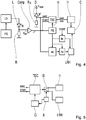
- Fig. 4 shows a circuit diagram of the receiving arrangement according to the invention in conjunction with a transmitting device.
- the transmitting means comprises a pulse generator PG which supplies a laser driver LD with a corresponding signal to output a laser pulse at given times via the semiconductor laser L which is in an array in which many such laser diodes are arranged.
- the laser diode L is connected via a resistor R to ground. Between the laser diode L and the resistor R, the output signal of the laser diode is output as a voltage to the comparator Comp and compared with the reference voltage V ref . In response, a pulse is output as a start signal to the receiving device.
- This start signal is applied to the time-to-digital conversion TDC and to a phase shifter PS.
- the light signals are presently received with the diode D, which stands for an entire diode array. It is present, as stated above, to a SPAD. This is under the bias V spad .
- the diode D is switched to ground via the quench resistor.
- the so-called quenching takes place via the quench resistance RQ: the avalanche effect is throttled and ultimately stopped, in the present case by the resistance RQ. Again, this happens in a time that is much less than 1 ns. This quenching is necessary to prevent self-destruction of the photodiode. Quenching with a resistor, which is most commonly used, is called passive quenching. There are even more complicated embodiments, which are then called accordingly.
- the signal event goes between the photodiode D and the quench resistor R Q in the block TDC, which performs the time-to-digital conversion.
- the start signal from the transmitting device also goes into this block.
- the time-to-digital conversion TDC is supplied by the block PS with the clock RC. This clock is also sent from the block RPS to the evaluation path parallel to the TDC starting with the event counter EC. Also in the Event Counter EC the signal event goes. This allows the SPAD signal to be processed in parallel by both the time-to-digital conversion and the event counter.
- the time-to-digital conversion TDC outputs the event time, ie the time at which the photon or photons were received by the diode D, to the histogram H.
- the time-to-digital conversion TDC uses, for example, a 500 MHz reference clock and internally generates, for example via a delay circuit, a high temporal resolution of, for example, 250 ps.
- the event counter which receives phase-shifted from the transmitter by the phase shifter PS according to the start signal, outputs a signal to the holding member ho.
- the event counter can count multiple events occurring in a 500 MHz interval asynchronously. With each clock cycle, the current count is buffered in a latch and subsequently added to the value of the corresponding memory location.
- the signal ho of the holding member is entered into another histogram LRH, which has a lower resolution than the histogram H.
- the memory location of this histogram LRH is also selected by the so-called Bin Counter bc.
- the Bin Counter bc is also reset by the Start signal. Both the histogram H and the histogram LRH output their signal to a block C which compares these signals. Due to signal deviations, this block C may allow small differences in the histograms.
- the counter EC can also be executed in certain constellations as a 1-bit counter.
- a single SPAD cell usually has a dead time of 10 to 20 ns. Therefore, in a 2ns interval (500MHz clock) only a single event can occur.
- SPAD cells in parallel via a combination logic to a time measuring unit.
- multiple SPAD triggers may occur in a 2ns reference clock cycle, and a counter of correspondingly more word width is needed.
- the reference clock can also be chosen significantly lower than 500 MHz, which can also occur more events per time interval.
- Fig. 5 shows a partial circuit diagram of another embodiment of the receiving circuit according to the invention.
- TDC time-to-digital conversion
- the signals event from the photodiodes and signal start from the transmitting device. From this, the time at which the photons have arrived in the receiving device after they have been sent is again determined accordingly. This time is either output to the histogram H or to the histogram LRH, depending on the resolution with which the time-to-digital conversion TDC is working. In the histogram H is only with high resolution so for example.
- Fig. 6 shows in a flow chart the inventive method.
- the photodiodes D convert the received light signals into electrical signals.
- these electrical signals are used to perform a distance determination in which a time-correlated photon count is performed. In this case, a time-to-digital conversion is used, which is now performed twice to eliminate random sources of error.
Landscapes
- Engineering & Computer Science (AREA)
- Physics & Mathematics (AREA)
- Computer Networks & Wireless Communication (AREA)
- General Physics & Mathematics (AREA)
- Radar, Positioning & Navigation (AREA)
- Remote Sensing (AREA)
- Electromagnetism (AREA)
- Optical Radar Systems And Details Thereof (AREA)
Abstract
Description
- Die Erfindung betrifft eine Empfangsanordnung zum Empfang von Lichtsignalen bzw. ein Verfahren zum Empfangen von Lichtsignalen nach der Gattung der unabhängigen Patentansprüche.
- Aus
WO 2017/081294 A1 sind eine Vorrichtung und ein Verfahren zur optischen Distanzmessung bekannt. Dabei wird eine Sendematrix zum Versenden von Messpulsen und eine Empfangsmatrix zum Empfangen der reflektieren Messpulse verwendet. Zum Versenden der Messpulse wird eine Untermenge der Sendematrix verwendet. - Die erfindungsgemäße Empfangsanordnung zum Empfang von Lichtsignalen bzw. das erfindungsgemäße Verfahren zum Empfangen von Lichtsignalen mit den Merkmalen der unabhängigen Patentansprüche haben demgegenüber den Vorteil, dass nunmehr die Entfernungsmessung mittels Lichtsignalen dadurch besser abgesichert wird, dass eine zeitkorrelierte Photonenzählung wenigstens zweimal durchgeführt wird. Durch diese Maßnahme wird insbesondere bei LiDAR-Anwendungen im Fahrzeugbereich eine hohe Datenintegrität in der Signalverarbeitung erreicht. Die bei der zeitkorrelierten Photonenzählung verwendete Bestimmung von Histogrammen und die weiteren Verarbeitungsschritte werden dadurch effektiv gegen Fehler geschützt. Es gibt verschiedene Fehlerszenarien, die insbesondere bei der Histogrammberechnung auftreten können. Bspw. können zufällig Speicherwerte durch Strahlung verändert werden. Es kann ein Lese- oder Schreibadressenfehler auftreten. Es kann ein Wert in seiner Höhe zufällig verändert werden. Solche Fehler werden durch die Erfindung in ihrer Auswirkung vermieden. Da bspw. bei LiDAR-Anwendung im Fahrzeug solche Umfeldinterpretationen dazu verwendet werden können, das Fahrzeug in seiner Bewegung zu beeinflussen, muss vorliegend eine hohe Zuverlässigkeit der Signalverarbeitung gewährleistet sein.
- Bei der Empfangsanordnung handelt es sich vorliegend um eine Baugruppe, die den angegebenen Lichtempfänger und eine Auswerteschaltung aufweist. Dies kann als einstückiges Modul vorliegen, es kann jedoch auch sein, dass die Empfangsanordnung verteilt vorliegt, also nicht als eine einzige Baugruppe. Empfangen werden die Lichtsignale, die üblicherweise vorher mit einer vorliegenden Sendeeinrichtung versendet wurden. Insbesondere zur Entfernungsmessung hat sich die LiDAR-Technik als geeignet erwiesen. Dabei ist für die Umfeldinterpretation von Fahrzeugen eine Erfassung der Umgebung durch solche Lasersignale möglich. Diese Lasersignale werden durch Halbleiterlaser üblicherweise sogar Laserarrays also Feldern von solchen Lasern erzeugt. Dafür werden die aus dem Stand der Technik bekannten VCSEL verwendet. Diese sind in Halbleitertechnik in zuverlässiger und einfacher Art und Weise herzustellen. Üblicherweise werden für LiDAR-Anwendungen Wellenlängen im Infrarotbereich verwendet. Es können jedoch auch Wellenlängen im sichtbaren Bereich verwendet werden.
- Als Lichtsignale werden vorzugsweise Laserimpulse verwendet, die vorzugsweise innerhalb einer Zeitperiode von zwei Mikrosekunden versendet werden, d.h. pro Periode wird ein Impulspaket mit einer Breite von bspw. 5ns versendet. Diese zwei Mikrosekunden entsprechen einer einfachen Entfernung um das Fahrzeug von 300 Metern. Die Entfernungsbestimmung erfolgt üblicherweise durch die sogenannte Time-of-flight-Methode, d.h. es wird die Zeit gemessen, die das Licht braucht, um vom Sender ausgestrahlt zu werden und beim Empfänger anzukommen. Dazu verwendet der Empfänger ein Startsignal, das die Lichtemission der Lichtsignale signalisiert, und die empfangenen Lichtsignale. Aus der Zeitdifferenz zwischen dem Startsignal und der Empfangszeit für die empfangenen Lichtsignale oder Lichtimpulse kann der Empfänger die Entfernung der Objekte bestimmen. Das Startsignal wird vom Sender eleltrisch und/oder optisch an den Empfänger übertragen.
- Als Lichtempfänger wird üblicherweise ein Feld von sogenannten Single-Photon-Avalanche-Diodes (SPAD) verwendet. Diese Dioden werden unter großer hoher Sperrspannung, die über der Durchbruchsspannung liegt, betrieben im sogenannten Geiger-Modus, sodass bereits im Prinzip ein Photon genügt, um den Lawinenprozess auszulösen. Da jedoch Streulicht vorliegt, wird es eine gewisse Rauschwelle geben, ab der der Lawineneffekt erst zum Tragen kommt. Es sind jedoch auch andere Lichtempfänger vorliegend möglich.
- Die Funktion des Lichtempfängers ist, das optische Signal in ein elektrisches Signal zu wandeln. Dies gelingt durch den lichtelektrischen Effekt.
- Der Lichtempfänger ist weiterhin an eine Auswerteschaltung angeschlossen, die aus den elektrischen Signalen mittels einer zeitkorrelierten Photonenzählung, die die elektrischen Signale zu Zeiten zuordnet, eine Entfernung zwischen der Empfangsanordnung und dem wenigstens einen Objekt, an dem die Lichtsignale reflektiert werden, bestimmt. Hierzu verwendet die Auswerteschaltung auch das Startsignal vom Sender, das die Emission der Lichtsignale oder Lichtimpulse anzeigt. Dieses Startsignal kann bspw. von einem Pulsgenerator oder Lasertreiber des Senders stammen.
- Die Auswerteschaltung kann eine integrierte Schaltung sein, wobei die Funktionen hardware- und/oder softwaremäßig ausgeführt werden. Es ist möglich, dass eine Mehrzahl von integrierten Schaltungen vorliegt aber auch diskrete Bauelemente oder Kombinationen aus diesen Bausteinen.
- Die zeitkorrelierte Photonenzählung ist vorliegend die Methode, um die Flugzeit zu bestimmen. Dabei wird aus dem elektrischen Signal, das die Photonen erzeugt haben, eine Zeit bestimmt und diese Zeit wird in ein Histogramm eingetragen. Durch eine Maximumsuche wird dann diese Zeit nach vielen Messungen gesucht, die die meisten Treffer hat. Es wird dann angenommen, dass der Lichtimpuls für diese Zeit vom Sender bis zum Empfänger gebraucht hat und daraus kann dann zwanglos die Entfernung bestimmt werden. Hierzu wird wie oben beschrieben auch das Startsignal verwendet.
- Bei der zeitkorrelierten Photonenzählung werden einzelne empfangene Photonen der ausgesendeten Lichtimpulse detektiert und gezählt und in ein Histogramm eingetragen und zwar an welcher Stelle, in zeitlicher Hinsicht gesehen, das oder die Photonen auftreten bezogen auf das Aussenden der Lichtimpulse. Das Aussenden des Lichtimpulses und die Zählung werden viele Male wiederholt. Dadurch gelingt eine sehr genaue Zeitmessung des Laserimpulses. Bspw. wird ein Objekt von einer Sendeeinrichtung mit vielen Photonen getroffen, die dann durch die Empfängeranordnung empfangen werden. Durch das häufige Wiederholen dieser Photonenbestimmung ist es möglich, den Lichtimpuls bzgl. seiner Flugzeit genau zu bestimmen. Vorliegend liefern die SPADs (Single Photon Avalanche Diodes) in der Empängeranordnung jeweils einen binären Impuls bei der Detektion eines Photons. Die Zeitpunkte der Impulse werden mit Zeit-Digital-Wandlern ermittelt und dann in das Histogramm eingetragen. So wird vorliegend die zeitkorrelierte Photonenzählung realisiert.
- Erfindungsgemäß wird nunmehr die zeitkorrelierte Photonenzählung wenigstens zweimal durchgeführt. Die kann parallel erfolgen oder sequentiell. Erfolgt es parallel, sollen die Ausgangssignale der selben Empfängerelemente bspw. einer SPAD von bspw. zwei Auswerteschaltungen ausgewertet werden. Diese Auswerteschaltungen können gleich oder unterschiedlich sein, bspw. können sie sich in der Genauigkeit unterscheiden. Damit sollen insbesondere zufällige Fehler erfasst werden und aus dem Auswerteprozess eliminiert werden, sodass mit der Auswertung des LiDAR-Signals keine falschen Steuersignale in einem Fahrzeug oder einer anderen Anwendung, für die das LiDAR verwendet wird, bestimmt werden.
- Die elektrischen Signale sind insbesondere Digitalsignale, wobei der Lichtempfänger ein analoges Signal ausgibt, aus dem dann ein Digitalsignal oder zumindest ein Impuls erzeugt wird.
- Das Objekt an dem die Lichtsignale reflektiert werden ist ein Objekt, das von der Sendeeinrichtung durch die Lichtsignale bestrahlt wird und dessen Reflexion bei der Empfangsanordnung ankommen. Dabei kann es sich im Verkehr bspw. um ein anderes Auto, einen Fußgänger oder ein feststehendes Objekt handeln.
- Es wird vorgeschlagen, die zeitkorrelierte Photonenzählung wenigstens zweimal durchzuführen. Es ist möglich sie mehr als zweimal durchzuführen, um eine größere Absicherung des Ergebnisses zu erreichen als wenn es nur zweimal durchgeführt worden wäre.
- Durch die in abhängigen Ansprüchen angegebenen Maßnahmen und Weiterbildung sind vorteilhafte Ausgestaltungen der Erfindung möglich.
- Von Vorteil ist, dass die Auswerteschaltung die wenigstens eine zweite zeitkorrelierte Photonenzählung mit einer niedrigeren zeitlichen Auflösung als die erste zeitkorrelierte Photonenzählung ausführt. Da es sich hier um Absicherungszwecke handelt, kann eine niedrigere Auflösung verwendet werden. Dies spart Ressourcen und Verarbeitungszeit.
- Weiterhin ist von Vorteil, dass die erste zeitkorrelierte Photonenzählung eine viermal, achtmal oder sechzehnmal höhere Auflösung aufweist als die wenigstens eine zweite zeitkorrelierte Photonenzählung. D. h. es ist möglich, bis auf ein Viertel, Achtel oder Sechzehntel der Auflösung herunterzugehen, um die zweite zeitkorrelierte Photonenzählung zur Absicherung durchzuführen. Damit sind entsprechende Einsparungen möglich.
- Darüber hinaus ist es von Vorteil, dass für die erste und die wenigstens eine weitere zeitkorrelierte Photonenzählung eine jeweilige Zeit-Digital-Wandlung vorgesehen ist. Dies bedeutet, dass zwei getrennte Hardwarepfade für die erste und die weitere zeitkorrelierte Photonenzählungen vorliegen. Dies ermöglicht eine gute Absicherung des Ergebnisses, denn es ist dann unwahrscheinlicher, dass beide Hardwarepfade gleichzeitig durch eine Fehlerquelle beeinflusst werden. Alternativ ist es jedoch möglich, dass die Zeit-Digital-Wandlung rein softwaremäßig durchgeführt wird und dass zwei verschiedene Softwareprogramme vorliegen, die jeweils die Zeit-Digital-Wandlung durchführen. Dies kann auch auf der gleichen Hardware durchgeführt werden. Das gleiche Programm kann die die Zeit-Digital-Wandlung alternativ auch nacheinander ausführen. Damit wird dann durch die unterschiedlichen Zeiten der Ausführung der Zeit-Digital-Wandlung eine Trennung durchgeführt, um die oben genannten Fehlerquellen auszuschalten.
- Vorteilhaft ist, dass die Zeit-Digital-Wandlung für die wenigstens eine zweite zeitkorrelierte Photonenzählung einen Zähler aufweist. Dies stellt eine einfachere Variante einer Zeit-Digital-Wandlung dar als bspw. die Ausprägung, die im Folgenden dargestellt wird.
- Eine Zeit-Digital-Wandlung ist ein Verfahren, um eine Zeit beispielsweise zwischen zwei Impulsen zu bestimmen und in ein Digitalwort umzusetzen. Dazu kann bspw. ein Zähler verwendet werden, der durch ein Start- und ein Stoppsignal bspw. des empfangenen Lichtimpulses bzw. des ausgesendeten Lichtimpulses aktiviert wird. Um den Fehler zu Beginn und zu Ende des durch den Zähler ermittelten Zählerstandes zu bestimmen, wird eine sogenannte Interpolation verwendet. Dazu kann eine Verzögerungsschaltung verwendet werden. Es ist jedoch auch möglich, zwei zueinander verstimmte Oszillatoren zu verwenden oder eine sogenannte Überabtastung bspw. eine Vierfach-Überabtastung zu verwenden und damit das Signal abzutasten. Durch den Zählerstand und die Werte, die aus der Interpolation gewonnen werden zu Beginn der Zählung und zu Ende der Zählung, kann dann die Zeit und damit die Flugzeit genau gemessen werden.
- Der Vorteil dieser Methode besteht in der hohen zeitlichen Auflösung von ca. 100 ps. Dies entspricht einer Abtastrate von 10 GHz oder einer Distanzmessgenauigkeit von 1,4 cm.
- Weiterhin ist es vorteilhaft, dass eine Plausibilisierungseinheit vorgesehen ist, die anhand von Daten der ersten und wenigstens einen zweiten zeitkorrelierten Photonenzählung ein Plausibilisierungssignal ausgibt. Dies ermöglicht eine zusätzliche Absicherung, ob die zeitkorrelierten Photonenzählungen plausible Werte ausgeben. Dies kann bspw. dadurch realisiert werden, dass die Summen von vier oder acht benachbarten Histogrammeinträgen der ersten und der zweiten Photonenzählung gleich sind oder zumindest einen erlaubten Unterschied aufweisen.
- Darüber hinaus ist von Vorteil, dass die Daten für diese Plausibilisierung eine Anzahl von Zählungen in einem bestimmten Zeitabschnitt sind oder eine Objektdetektion. Über die Zahl der Zählungen kann eine Plausibilisierung der beiden Messungen in dem Histogramm mit der hohen und mit der niedrigen Auflösung durchgeführt werden. Aber auch mit der Objektdetektion, d.h. der Entfernungsbestimmung oder andere Objektparameter kann eine solche Plausibilisierung der beiden Histogramme erfolgen.
- Es ist von Vorteil, dass die erste und wenigstens eine zweite zeitkorrelierte Photonenzählung auf getrennten Auswertepfaden in der Auswerteschaltung bestimmt werden. Dies gibt explizit an, dass die zeitkorrelierten Photonenzählungen auf getrennten Auswertepfaden ausgeführt werden und damit eine hohe Absicherung hinsichtlich des Ergebnisses besteht.
- Weiterhin ist es von Vorteil, dass der Zähler im zweiten Auswertepfad mit einem Baustein zur Phasenverschiebung verbunden ist, da ein Referenztakt, mit dem der Zähler versorgt wird, in Abhängigkeit vom Startsignal, das von einer Sendeschaltung empfangen wird, verzögert wird. Damit wird die zweite zeitkorrelierte Photonenzählung auf das Startsignal der Sendeschaltung eingestellt und mit dem gleichen Phasenverzug im Vergleich zum Referenztakt versehen. Dies ermöglicht eine bessere Signalverarbeitung.
- Ausführungsbeispiele der Erfindung sind in der Zeichnung dargestellt und werden in der nachfolgenden Beschreibung näher erläutert.
- Es zeigen:
-
Fig. 1 ein Fahrzeug und ein Objekt, -
Fig. 2 ein erstes Blockschaltbild der erfindungsgemäßen Empfangsanordnung, -
Fig. 3 ein zweites Blockschaltbild der erfindungsgemäßen Empfangsanordnung, -
Fig. 4 eine erste Schaltung der erfindungsgemäßen Empfangsanordnung, -
Fig. 5 ein Teilschaltbild der erfindungsgemäßen Empfangsanordnung und -
Fig. 6 ein Flussdiagramm des erfindungsgemäßen Verfahrens. -
Fig. 1 zeigt ein Fahrzeug V, das sich in die Richtung R bewegt. Das Fahrzeug V weist die LiDAR-Module Li1 bis Li6 auf. Bei einem LiDAR-Modul handelt es sich um eine Sendeeinrichtung zur Versendung von Lichtsignalen und der erfindungsgemäßen Empfangsanordnung zum Empfang von den dann reflektierten Lichtsignalen. Diese LiDAR-Module erfassen die Umgebung des Fahrzeugs V. Es können mehr oder weniger LiDAR-Module verwendet werden und auch an weiteren Stellen des Fahrzeugs V. Daher wird das Objekt OB durch das LiDAR-Modul Li1 erfasst. Durch eine Entfernungsbestimmung und entsprechende Charakterisierung anhand der Bewegungsparameter des Objekts ist es möglich, auf eine mögliche Kollision zu schließen und entsprechende Bewegungen des Fahrzeugs V zu beeinflussen, um nicht mit dem Objekt OB zu kollidieren. - Die LiDAR-Module Li1 bis Li6 weisen eine erfindungsgemäße Empfängeranordnung auf und eine Sendereinrichtung, die wie oben beschrieben mit einem Laserarray die Laserimpulse versendet, um die am Objekt OB reflektierten Laserimpulse dann mit einem SPAD-Array zu empfangen und dann entsprechend mit der zeitkorrelierten Photonenzählung auszuwerten, um die Entfernung zwischen dem Objekt OB und dem Fahrzeug V zu bestimmen. Dafür wird die Time-of-Flight-Methode verwendet.
-
Fig. 2 zeigt in einem ersten Blockschaltbild die erfindungsgemäße Empfangsanordnung. Ein Wandler 20 wandelt das optische Signal also das Lichtsignal in ein elektrisches Signal. Dieses elektrische Signal wird an eine Analog-Digital-Wandlung 21 weitergegeben. Die Analog-Digital-Wandlung kann eine Einrichtung sein, die aus dem Signal des Wandlers 20, vorzugsweise eine SPAD, ein Digitalsignal erzeugt, was auch als Ereignissignal oder Event bezeichnet werden kann. Es kann jedoch auch lediglich eine Impulsbildung oder Impulsverlängerung vorgesehen sein. - Das so umgeformte elektrische Signal, das auch noch weitere Verarbeitungsschritte durchlaufen kann, wird dann auf zwei getrennte Hardwarepfade gegeben, indem im ersten Hardwarepfad oder Auswertepfad eine erste zeitkorrelierte Photonenzählung ZPZ1 und im zweiten Auswertepfad eine zweite zeitkorrelierte Photonenzählung ZPZ2 ausgeführt werden. Diese Signale werden an einen Auswertebaustein A weitergegeben, indem dann mit diesen Signalen die beiden Histogramme einmal eines mit höherer Auflösung und zum anderen eines mit niedriger Auflösung oder sogar mit gleicher Auflösung gefüllt werden. Durch eine Maximumsuche nach vielen Zählungen und dem Füllen dieser Histogramme wird dann die Entfernung in den beiden Histogrammen von der Empfangsschaltung zum Objekt bestimmt und diese Ergebnisse werden miteinander abgeglichen, ob vorliegend ein plausibles Signal vorliegt. Für die Entfernungsbestimmung wird wie oben angegeben ein Startsignal für die Emission der Laserimpulse verwendet, das vom Sender an die Empfangsanordnung übergeben wird.
- Dann wird das Entfernungssignal oder eine Ableitung davon über den Schnittstellenbaustein IF an weitere Verarbeitungseinheiten abgegeben, um bspw. Fahrzeugfunktionen auszurechnen.
-
Fig. 3 zeigt ein zweites Blockschaltbild der erfindungsgemäßen Empfangsanordnung. Wiederum wird im Block 20 aus den Lichtsignalen ein elektrisches Signal erzeugt. Dies wird dann im Block 21 wiederum in ein digitales Signal umgewandelt. Im Block ZPZ3 erfolgt die zeitkorrelierte Photonenzählung. Diese wird vorliegend zweimal durchgeführt und die entsprechenden Signale werden dann sukzessive an den Auswertebaustein A weitergegeben, der wiederum die beiden Histogramme füllt. In analoger Weise wird über Schnittstellenbaustein IF die Entfernungsbestimmung oder ein abgeleitetes Signal davon weitergegeben. Bei der zeitkorrelierten Photonenzählung wird das Aussenden des Laserimpulses vielfach wiederholt. Vor Beginn der wiederholten Messung werden alle Speicherstellen im jeweiligen Histogramm mit bspw. hoher und niedriger Auflösung auf Null gesetzt. -
Fig. 4 zeigt ein Schaltbild der erfindungsgemäßen Empfangsanordnung in Verbindung mit einer Sendeeinrichtung. Die Sendeeinrichtung weist einen Pulsgenerator PG auf, der einen Lasertreiber LD mit einem entsprechenden Signal versorgt, um einen Laserimpuls zu gegebenen Zeiten auszugeben über den Haltleiterlaser L, der in einem Array vorliegt, in dem viele solcher Laserdioden angeordnet sind. Die Laserdiode L ist über einen Widerstand R mit Masse verbunden. Zwischen der Laserdiode L und dem Widerstand R wird das Ausgangssignal der Laserdiode als Spannung an den Komparator Comp ausgegeben und mit der Referenzspannung Vref verglichen. In Abhängigkeit davon wird ein Impuls als Startsignal an die Empfangsanordnung ausgegeben. - Dieses Startsignal geht an die Zeit-Digital-Wandlung TDC und an einen Phasenshifter PS. Die Lichtsignale werden vorliegend mit der Diode D empfangen, die für ein ganzes Diodenarray steht. Es handelt sich vorliegend, wie oben ausgeführt, um eine SPAD. Diese ist unter der Vorspannung Vspad. Die Diode D wird über den Quench-Widerstand gegen Masse geschaltet. Über den Quenchwiderstand RQ erfolgt das sogenannte Quenching: Der Lawineneffekt wird gedrosselt und letztlich gestoppt, vorliegend durch den Widerstand RQ. Auch dies geschieht in einer Zeit, die sehr viel kleiner als 1 ns ist. Dieses Quenchen ist notwendig, um die Selbstzerstörung der Photodiode zu verhindern. Das Quenchen mit einem Widerstand, was am häufigsten verwendet wird, wird als passives Quenchen bezeichnet. Es gibt noch kompliziertere Ausgestaltungen, die dann entsprechend genannt werden.
- Das Signal event geht zwischen der Photodiode D und dem Quench-Widerstand RQ in den Block TDC, der die Zeit-Digital-Wandlung ausführt. In diesen Block geht auch das Startsignal von der Sendeeinrichtung. Weiterhin wird die Zeit-Digital-Wandlung TDC von dem Block PS mit dem Takt RC versorgt. Dieser Takt wird vom Block RPS auch an den zur TDC parallelen Auswertepfad beginnend mit dem Event Counter EC gesendet. Auch in den Event Counter EC geht das Signal event. Damit kann das Signal von der SPAD sowohl von der Zeit-Digital-Wandlung als auch vom Event Counter parallel verarbeitet werden. Die Zeit-Digital-Wandlung TDC gibt die Eventtime, also die Zeit zu der das Photon oder die Photonen durch die Diode D empfangen wurden, an das Histogramm H aus. Dort wird im Histogramm die entsprechende Zeit eingetragen, d.h. in dem Histogramm wird der Wert der Speicherstelle um eins erhöht, der der Laufzeit seit Aussenden des Laserimpulses entspricht. Die Zeit-Digital-Wandlung TDC verwendet bspw. einen 500MHz Referenztakt und erzeugt intern bspw. über eine Verzögerungsschaltung eine hohe zeitliche Auflösung von bspw. 250ps.
- Der Event Counter, der vom Phaseshifter PS den Takt entsprechend dem Startsignal vom Sender phasenverschoben erhält, gibt ein Signal an das Halteglied ho aus. Über den Phasenshifter PS kann der Event Counter in der 500MHz Basis in der Phasenlage an den Startimpuls (=Startsignal) angglichen werden, der auch als Referenz für den Start der Zeit-Digitalwandlung TDC herangezogen wird. Dadurch ist es möglich, die Zeitbereiche der Event-Aggregation mehrerer Speicherstellen des 250ps-Histogramms zu synchronisieren.
- Der Event Counter kann mehrere Ereignisse, die in einem 500MHz-lntervall auftreten, asynchron zählen. Mit jedem Taktzyklus wird der aktuelle Zählerstand in einem Halteglied zwischengespeichert und nachfolgend zu dem Wert der entsprechenden Speicherstelle addiert. Das Signal ho des Halteglieds wird in ein weiteres Histogramm LRH eingetragen, das eine niedrigere Auflösung als das Histogramm H aufweist. Die Speicherstelle dieses Histogramms LRH wird auch noch von dem sogenannten Bin Counter bc ausgewählt. Der Bin Counter bc wird durch das Signal Start ebenfalls resetiert. Sowohl das Histogramm H als auch das Histogramm LRH geben ihr Signal an einen Block C aus, der diese Signale vergleicht. Aufgrund von Signalabweichungen kann dieser Block C kleine Unterschiede in den Histogrammen erlauben.
- Der Zähler EC kann in bestimmten Konstellationen auch als 1-bit Zähler ausgeführt werden. Eine einzelne SPAD Zelle hat in der Regel eine Totzeit von 10 bis 20 ns. Daher kann in einem 2ns Intervall (500MHz Takt) nur ein einziger Event auftreten.
- Es ist aber auch möglich, mehrere SPAD-Zellen parallel über eine Kombinationslogik an einer Zeitmesseinheit anzuschließen. In diesem Fall können in einem 2ns Referenztaktzyklus mehrere SPAD Auslösungen auftreten, und es wird ein Zähler mit entsprechend mehr Wortbreite benötigt.
- Schließlich kann der Referenztakt auch deutlich niedriger als 500 MHz gewählt werden, wodurch ebenfalls mehr Events pro Zeitintervall auftreten können.
-
Fig. 5 zeigt ein Teilschaltbild einer weiteren Ausführung der erfindungsgemäßen Empfangsschaltung. Vorliegend ist nun kein zweiter Auswertepfad mehr vorhanden, sondern nur eine einzige Zeit-Digital-Wandlung TDC, die dann einer gesonderten Prüfung unterzogen werden muss. In die Zeit-Digital-Wandlung gehen die Signale event von den Photodioden und Signal Start von der Sendeeinrichtung ein. Daraus wird wieder entsprechend die Zeit ermittelt, mit der die Photonen in der Empfangseinrichtung nach ihrem Versenden angekommen sind. Diese Zeit wird entweder, je nachdem mit welcher Auflösung die Zeit-Digital-Wandlung TDC arbeitet, an das Histogramm H oder an das Histogramm LRH ausgegeben. In das Histogramm H wird erst mit hoher Auflösung also bspw. der achtfachen Auflösung eingetragen und in das Histogramm LRH mit der entsprechend niedrigeren. Dies nimmt eine Schalteinrichtung S vor, die einen Schalter SL entsprechend ansteuert. Diese Steuerung S steuert auch einen Taktgeber CL an, der in der Lage ist, die Zeit-Digital-Wandlung vom Takt herunterzunehmen, um so die Auflösung zu reduzieren. Es sind auch andere Möglichkeiten denkbar, um den Takt zu reduzieren und damit die Auflösung. -
Fig. 6 zeigt in einem Flussdiagramm das erfindungsgemäße Verfahren. In Verfahrensschritt 600 wandeln die Photodioden D die empfangenen Lichtsignale in elektrische Signale. In Verfahrensschritt 601 werden diese elektrischen Signale dazu verwendet, eine Enfernungsbestimmung durchzuführen, in dem eine zeitkorrelierte Photonenzählung durchgeführt wird. Dabei wird eine Zeit-Digital-Wandlung verwendet, die nun zweimal durchgeführt wird, um zufällige Fehlerquellen zu eliminieren. -
- OB
- Objekt
- V
- Fahrzeug
- R
- Richtung
- Li1-8
- LiDAR-Module
- 20
- Wandler von Lichtsignalen in elektrische Signale
- 21
- Analog-Digital-Wandlung
- ZPZ1
- erste zeitkorrelierte Photonenzählung
- ZPZ2
- zweite zeitkorrelierte Photonenzählung
- A
- Auswertebaustein
- IF
- Schnittstellenbaustein
- ZPZ3
- zeitkorrelierte Photonenzählung
- PG
- Pulsgenerator
- LD
- Lasertreiber
- L
- Laserdiode
- R
- Widerstand
- Comp
- Komparator
- Vref
- Referenzspannung
- Vspad
- Sperrspannung für SPAD
- D
- Lichtempfänger, SPAD
- Rq
- Quenchwiderstand
- TDC
- Zeit-Digital-Wandlung
- PS
- Phasenshifter
- ec
- Zähler
- ho
- Halteglied
- bc
- Bin-Zähler
- LRH
- Histogramm mit niedriger Auflösung
- H
- Histogramm mit hoher Auflösung
- C
- Vergleicher
- CI
- Taktgeber
- SI
- Schalter
- S
- Schalteinrichtung
- 600
- Verfahrensschritt
- 601
- Verfahrensschritt
Claims (10)
- Empfangsanordnung zum Empfang von Lichtsignalen mit:- einem Lichtempfänger, der die Lichtsignale in elektrische Signale wandelt,- einer Auswerteschaltung, die aus den elektrischen Signalen mittels einer zeitkorrelierten Photonenzählung, die die elektrischen Signale zu Zeiten zuordnet, und einem Startsignal für die Emission der Lichtsignale eine Entfernung zwischen der Empfangsanordnung und wenigstens einem Objekt bestimmt, wobei die zeitkorrelierte Photonenzählung wenigstens zweimal durchgeführt wird.
- Empfangsanordnung nach Anspruch 1, dadurch gekennzeichnet, dass die Auswerteschaltung die wenigstens eine zweite zeitkorrelierte Photonenzählung mit einer niedrigeren zeitlichen Auflösung als die erste zeitkorrelierte Photonenzählung ausführt.
- Empfangsanordnung nach Anspruch 2, dadurch gekennzeichnet, dass die erste zeitkorrelierte Photonenzählung eine viermal, achtmal oder sechzehnmal höhere Auflösung aufweist als die wenigstens eine zweite zeitkorrelierte Photonenzählung.
- Empfangsanordnung nach einem der vorhergehenden Ansprüche, dadurch gekennzeichnet, dass für jede zeitkorrelierte Photonenzählung eine jeweilige Zeit-Digital-Wandlung (TDC) vorgesehen ist.
- Empfangsanordnung nach Anspruch 4, dadurch gekennzeichnet, dass die Zeit-Digital-Wandlung für die wenigstens eine zweite Photonenzählung einen Zähler aufweist.
- Empfangsanordnung nach einem der vorhergehenden Ansprüche, dadurch gekennzeichnet, dass die eine Plausibilisierungseinheit vorgesehen ist, die anhand von Daten der ersten und wenigstens einen zweiten zeitkorrelierten Photonenzählung ein Plausibilisierungssignal ausgibt.
- Empfangsanordnung nach Anspruch 6, dadurch gekennzeichnet, dass die Daten eine Anzahl von Zählungen in einem bestimmten Zeitabschnitt sind oder eine Objektdetektion.
- Empfangsanordnung nach einem der vorhergehenden Ansprüche, dadurch gekennzeichnet, dass die erste und die wenigstens eine zweite zeitkorrelierte Photonenzählung auf getrennten Auswertepfaden in der Auswerteschaltung bestimmt werden.
- Empfangsanordnung nach Anspruch 8, dadurch gekennzeichnet, dass der Zähler im zweiten Auswertepfad mit einem Baustein zur Phasenverschiebung verbunden ist, der einen Referenztakt, mit dem der Zähler versorgt wird, in Abhängigkeit vom Startsignal, das von einer Sendeschaltung empfangen wird, verzögert.
- Verfahren zum Empfangen von Lichtsignalen mit folgenden Verfahrensschritten:- Wandeln der empfangenen Lichtsignale in elektrische Signale.- Bestimmen einer Entfernung zwischen einer Empfangsanordnung und einem Objekt mittels einer zeitkorrelierten Photonenzählung, die die elektrischen Signale zu Zeiten zuordnet, und einem Startsignal für die Emission der Lichtsignale, wobei die zeitkorrelierte Photonenzählung wenigstens zweimal durchgeführt wird.
Applications Claiming Priority (1)
| Application Number | Priority Date | Filing Date | Title |
|---|---|---|---|
| DE102018203533.4A DE102018203533A1 (de) | 2018-03-08 | 2018-03-08 | Empfangsanordnung zum Empfang von Lichtsignalen und Verfahren zum Empfangen von Lichtsignalen |
Publications (2)
| Publication Number | Publication Date |
|---|---|
| EP3537172A1 true EP3537172A1 (de) | 2019-09-11 |
| EP3537172B1 EP3537172B1 (de) | 2024-04-10 |
Family
ID=65408977
Family Applications (1)
| Application Number | Title | Priority Date | Filing Date |
|---|---|---|---|
| EP19156476.4A Active EP3537172B1 (de) | 2018-03-08 | 2019-02-11 | Empfangsanordnung zum empfang von lichtsignalen und verfahren zum empfangen von lichtsignalen |
Country Status (3)
| Country | Link |
|---|---|
| EP (1) | EP3537172B1 (de) |
| CN (1) | CN110244315B (de) |
| DE (1) | DE102018203533A1 (de) |
Cited By (3)
| Publication number | Priority date | Publication date | Assignee | Title |
|---|---|---|---|---|
| CN112305560A (zh) * | 2020-10-30 | 2021-02-02 | 中国科学院光电技术研究所 | 一种基于首光子组的单光子激光雷达快速成像方法 |
| US20220128691A1 (en) * | 2020-10-27 | 2022-04-28 | Denso Wave Incorporated | Laser radar |
| US11536835B2 (en) | 2018-05-30 | 2022-12-27 | Fraunhofer-Gesellschaft Zur Foerderung Der Angewandten Forschung E.V. | Laser measuring means for measuring a distance from an object, and method of operating same |
Families Citing this family (3)
| Publication number | Priority date | Publication date | Assignee | Title |
|---|---|---|---|---|
| DE102020203796B4 (de) | 2020-03-24 | 2025-07-17 | Fraunhofer-Gesellschaft zur Förderung der angewandten Forschung eingetragener Verein | Verfahren und Vorrichtung zum Bestimmen einer Messinformation und LiDAR-Gerät |
| CN111856485B (zh) * | 2020-06-12 | 2022-04-26 | 深圳奥锐达科技有限公司 | 一种距离测量系统及测量方法 |
| US20240027616A1 (en) * | 2020-11-27 | 2024-01-25 | Ningbo ABAX Sensing Electronic Technology Co., Ltd. | Distance information acquisition system |
Citations (3)
| Publication number | Priority date | Publication date | Assignee | Title |
|---|---|---|---|---|
| EP3091271A1 (de) * | 2015-05-05 | 2016-11-09 | Sick Ag | Lichttaster |
| US20170052065A1 (en) * | 2015-08-20 | 2017-02-23 | Apple Inc. | SPAD array with gated histogram construction |
| WO2017081294A1 (de) | 2015-11-11 | 2017-05-18 | Ibeo Automotive Systems GmbH | Verfahren und vorrichtung zur optischen distanzmessung |
Family Cites Families (10)
| Publication number | Priority date | Publication date | Assignee | Title |
|---|---|---|---|---|
| JP2003060500A (ja) * | 2001-08-09 | 2003-02-28 | Nippon Signal Co Ltd:The | カウンタ回路 |
| KR101690318B1 (ko) * | 2009-05-28 | 2016-12-27 | 코닌클리케 필립스 엔.브이. | 디지털 실리콘 광전자증배기들의 시간 분해능을 개선하기 위한 방법 |
| DE102010061382B4 (de) * | 2010-12-21 | 2019-02-14 | Sick Ag | Optoelektronischer Sensor und Verfahren zur Erfassung und Abstandsbestimmung von Objekten |
| US9354332B2 (en) * | 2011-04-05 | 2016-05-31 | Koninklijke Philips N.V. | Detector array with time-to-digital conversion having improved temporal accuracy |
| KR101871361B1 (ko) * | 2011-11-01 | 2018-08-03 | 삼성전자주식회사 | 고해상도 및 고대조도 영상을 동시에 생성하기 위한 광자 계수 검출 장치 및 방법 |
| EP2589980A1 (de) * | 2011-11-04 | 2013-05-08 | Leica Geosystems AG | Entfernungsmesser |
| CN103208994A (zh) * | 2013-03-11 | 2013-07-17 | 东南大学 | 一种两段式时间数字转换电路 |
| US10067224B2 (en) * | 2015-10-22 | 2018-09-04 | Stmicroelectronics (Research & Development) Limited | Time to digital converter (TDC) with synchronous output and related methods |
| CN105871371B (zh) * | 2016-03-25 | 2018-08-10 | 东南大学 | 一种基于锁相环的三段式时间数字转换电路 |
| US10145948B2 (en) * | 2016-07-13 | 2018-12-04 | Texas Instruments Incorporated | Methods and apparatus for narrowband ranging systems using coarse and fine delay estimation |
-
2018
- 2018-03-08 DE DE102018203533.4A patent/DE102018203533A1/de not_active Withdrawn
-
2019
- 2019-02-11 EP EP19156476.4A patent/EP3537172B1/de active Active
- 2019-03-07 CN CN201910171041.XA patent/CN110244315B/zh not_active Expired - Fee Related
Patent Citations (3)
| Publication number | Priority date | Publication date | Assignee | Title |
|---|---|---|---|---|
| EP3091271A1 (de) * | 2015-05-05 | 2016-11-09 | Sick Ag | Lichttaster |
| US20170052065A1 (en) * | 2015-08-20 | 2017-02-23 | Apple Inc. | SPAD array with gated histogram construction |
| WO2017081294A1 (de) | 2015-11-11 | 2017-05-18 | Ibeo Automotive Systems GmbH | Verfahren und vorrichtung zur optischen distanzmessung |
Non-Patent Citations (3)
| Title |
|---|
| MARKOVIC BOJAN ET AL: "Monolithic single-photon detectors and time-to-digital converters for picoseconds time-of-flight ranging", SENSORS, CAMERAS, AND SYSTEMS FOR INDUSTRIAL, SCIENTIFIC, AND CONSUMER APPLICATIONS XII, SPIE, 1000 20TH ST. BELLINGHAM WA 98225-6705 USA, vol. 7875, no. 1, 10 February 2011 (2011-02-10), pages 1 - 6, XP060005640, DOI: 10.1117/12.872424 * |
| ROBERT A LAMB ET AL: "Pseudo-random single photon counting: Absolute rangefinding without alaising", ELECTRONICS, COMMUNICATIONS AND PHOTONICS CONFERENCE (SIECPC), 2011 SAUDI INTERNATIONAL, IEEE, 24 April 2011 (2011-04-24), pages 1 - 6, XP031993259, ISBN: 978-1-4577-0068-2, DOI: 10.1109/SIECPC.2011.5876950 * |
| SCHULTZ STEVEN E ET AL: "Low-SWaP coincidence processing for Geiger-mode LIDAR video", VISUAL COMMUNICATIONS AND IMAGE PROCESSING; 20-1-2004 - 20-1-2004; SAN JOSE,, vol. 9465, 19 May 2015 (2015-05-19), pages 94650F - 94650F, XP060054775, ISBN: 978-1-62841-730-2, DOI: 10.1117/12.2180991 * |
Cited By (5)
| Publication number | Priority date | Publication date | Assignee | Title |
|---|---|---|---|---|
| US11536835B2 (en) | 2018-05-30 | 2022-12-27 | Fraunhofer-Gesellschaft Zur Foerderung Der Angewandten Forschung E.V. | Laser measuring means for measuring a distance from an object, and method of operating same |
| US20220128691A1 (en) * | 2020-10-27 | 2022-04-28 | Denso Wave Incorporated | Laser radar |
| US11965963B2 (en) * | 2020-10-27 | 2024-04-23 | Denso Wave Incorporated | Laser radar |
| CN112305560A (zh) * | 2020-10-30 | 2021-02-02 | 中国科学院光电技术研究所 | 一种基于首光子组的单光子激光雷达快速成像方法 |
| CN112305560B (zh) * | 2020-10-30 | 2022-06-14 | 中国科学院光电技术研究所 | 一种基于首光子组的单光子激光雷达快速成像方法 |
Also Published As
| Publication number | Publication date |
|---|---|
| CN110244315B (zh) | 2024-05-31 |
| DE102018203533A1 (de) | 2019-09-12 |
| CN110244315A (zh) | 2019-09-17 |
| EP3537172B1 (de) | 2024-04-10 |
Similar Documents
| Publication | Publication Date | Title |
|---|---|---|
| EP3537172B1 (de) | Empfangsanordnung zum empfang von lichtsignalen und verfahren zum empfangen von lichtsignalen | |
| EP3537180B1 (de) | Empfängeranordnung zum empfang von lichtimpulsen, lidar-modul und verfahren zum empfangen von lichtimpulsen | |
| EP3185038B1 (de) | Optoelektronischer sensor und verfahren zur messung einer entfernung | |
| DE102014100696B3 (de) | Entfernungsmessender Sensor und Verfahren zur Erfassung und Abstandsbestimmung von Objekten | |
| EP2189814B1 (de) | Optoelektronischer Sensor und Verfahren zur Messung von Entfernungen nach dem Lichtlaufzeitprinzip | |
| EP2189805B1 (de) | Optoelektronischer Sensor und Verfahren zur Messung von Entfernungen nach dem Lichtlaufzeitprinzip | |
| EP3557286B1 (de) | Optoelektronischer sensor und verfahren zur erfassung und abstandsbestimmung eines objekts | |
| EP3611535A1 (de) | Erfassen von licht mit einer vielzahl von lawinenphotodiodenelementen | |
| WO2019115185A1 (de) | Empfangsanordnung zum empfang von lichtsignalen | |
| WO2019115184A1 (de) | Anordnung und verfahren zur ermittlung einer entfernung wenigstens eines objekts mit lichtsignalen | |
| DE102017202957B4 (de) | Empfängeranordnung, Halbleiterbaustein und Verfahren zum Empfang von Lichtimpulsen und zur Ausgabe eines Empfangssignals | |
| DE102018220688A1 (de) | Analog-Digital-Wandler | |
| EP3091271A1 (de) | Lichttaster | |
| EP3671276B1 (de) | Optoelektronischer sensor und verfahren zur erfassung eines objekts | |
| DE102015103472B4 (de) | Entfernungsmessender Sensor und Verfahren zur Erfassung und Abstandsbestimmung von Objekten | |
| EP3770633B1 (de) | Optoelektronischer sensor und verfahren zur abstandsbestimmung | |
| EP3994481B1 (de) | Auslesevorrichtung und lidar-messvorrichtung | |
| WO2007054422A2 (de) | Verfahren zur umfelderfassung | |
| EP3839556A1 (de) | Optoelektronischer sensor und verfahren zur erfassung eines objekts | |
| DE102016224509A1 (de) | Empfängeranordnung und Verfahren zum Empfang wenigstens eines Lichtimpulses und zur Ausgabe eines Empfangssignals | |
| DE102021118660A1 (de) | Laserscanner und Verfahren zur Erfassung von Objekten mit einem Laserscanner | |
| DE202018104258U1 (de) | Sicherheitslichtgitter | |
| DE102021116241A1 (de) | Sensor und Verfahren zur Bestimmung einer Laufzeit | |
| DE10032162C1 (de) | Verfahren und Vorrichtung zur Richtungserkennung von gepulsten Laserstrahlen nach dem Zeitintervallmeßprinzip | |
| EP3663798B1 (de) | Optoelektronischer sensor und verfahren zur erfassung und abstandsbestimmung von objekten |
Legal Events
| Date | Code | Title | Description |
|---|---|---|---|
| PUAI | Public reference made under article 153(3) epc to a published international application that has entered the european phase |
Free format text: ORIGINAL CODE: 0009012 |
|
| STAA | Information on the status of an ep patent application or granted ep patent |
Free format text: STATUS: THE APPLICATION HAS BEEN PUBLISHED |
|
| AK | Designated contracting states |
Kind code of ref document: A1 Designated state(s): AL AT BE BG CH CY CZ DE DK EE ES FI FR GB GR HR HU IE IS IT LI LT LU LV MC MK MT NL NO PL PT RO RS SE SI SK SM TR |
|
| AX | Request for extension of the european patent |
Extension state: BA ME |
|
| STAA | Information on the status of an ep patent application or granted ep patent |
Free format text: STATUS: REQUEST FOR EXAMINATION WAS MADE |
|
| 17P | Request for examination filed |
Effective date: 20200311 |
|
| STAA | Information on the status of an ep patent application or granted ep patent |
Free format text: STATUS: EXAMINATION IS IN PROGRESS |
|
| 17Q | First examination report despatched |
Effective date: 20210413 |
|
| RAP1 | Party data changed (applicant data changed or rights of an application transferred) |
Owner name: IBEO AUTOMOTIVE SYSTEMS GMBH |
|
| RAP1 | Party data changed (applicant data changed or rights of an application transferred) |
Owner name: MICROVISION, INC. |
|
| P01 | Opt-out of the competence of the unified patent court (upc) registered |
Effective date: 20230530 |
|
| REG | Reference to a national code |
Ref country code: DE Ref legal event code: R079 Free format text: PREVIOUS MAIN CLASS: G01S0007486000 Ipc: G01S0007486500 Ref document number: 502019010996 Country of ref document: DE |
|
| RIC1 | Information provided on ipc code assigned before grant |
Ipc: G01S 7/4861 20200101ALI20231129BHEP Ipc: G01S 7/497 20060101ALI20231129BHEP Ipc: G01S 7/4865 20200101AFI20231129BHEP |
|
| GRAP | Despatch of communication of intention to grant a patent |
Free format text: ORIGINAL CODE: EPIDOSNIGR1 |
|
| STAA | Information on the status of an ep patent application or granted ep patent |
Free format text: STATUS: GRANT OF PATENT IS INTENDED |
|
| INTG | Intention to grant announced |
Effective date: 20240122 |
|
| GRAS | Grant fee paid |
Free format text: ORIGINAL CODE: EPIDOSNIGR3 |
|
| GRAA | (expected) grant |
Free format text: ORIGINAL CODE: 0009210 |
|
| STAA | Information on the status of an ep patent application or granted ep patent |
Free format text: STATUS: THE PATENT HAS BEEN GRANTED |
|
| AK | Designated contracting states |
Kind code of ref document: B1 Designated state(s): AL AT BE BG CH CY CZ DE DK EE ES FI FR GB GR HR HU IE IS IT LI LT LU LV MC MK MT NL NO PL PT RO RS SE SI SK SM TR |
|
| REG | Reference to a national code |
Ref country code: GB Ref legal event code: FG4D Free format text: NOT ENGLISH |
|
| REG | Reference to a national code |
Ref country code: CH Ref legal event code: EP |
|
| REG | Reference to a national code |
Ref country code: DE Ref legal event code: R096 Ref document number: 502019010996 Country of ref document: DE |
|
| REG | Reference to a national code |
Ref country code: IE Ref legal event code: FG4D Free format text: LANGUAGE OF EP DOCUMENT: GERMAN |
|
| REG | Reference to a national code |
Ref country code: LT Ref legal event code: MG9D |
|
| REG | Reference to a national code |
Ref country code: NL Ref legal event code: MP Effective date: 20240410 |
|
| PG25 | Lapsed in a contracting state [announced via postgrant information from national office to epo] |
Ref country code: NL Free format text: LAPSE BECAUSE OF FAILURE TO SUBMIT A TRANSLATION OF THE DESCRIPTION OR TO PAY THE FEE WITHIN THE PRESCRIBED TIME-LIMIT Effective date: 20240410 |
|
| PG25 | Lapsed in a contracting state [announced via postgrant information from national office to epo] |
Ref country code: NL Free format text: LAPSE BECAUSE OF FAILURE TO SUBMIT A TRANSLATION OF THE DESCRIPTION OR TO PAY THE FEE WITHIN THE PRESCRIBED TIME-LIMIT Effective date: 20240410 |
|
| PG25 | Lapsed in a contracting state [announced via postgrant information from national office to epo] |
Ref country code: IS Free format text: LAPSE BECAUSE OF FAILURE TO SUBMIT A TRANSLATION OF THE DESCRIPTION OR TO PAY THE FEE WITHIN THE PRESCRIBED TIME-LIMIT Effective date: 20240810 |
|
| PG25 | Lapsed in a contracting state [announced via postgrant information from national office to epo] |
Ref country code: BG Free format text: LAPSE BECAUSE OF FAILURE TO SUBMIT A TRANSLATION OF THE DESCRIPTION OR TO PAY THE FEE WITHIN THE PRESCRIBED TIME-LIMIT Effective date: 20240410 |
|
| PG25 | Lapsed in a contracting state [announced via postgrant information from national office to epo] |
Ref country code: FI Free format text: LAPSE BECAUSE OF FAILURE TO SUBMIT A TRANSLATION OF THE DESCRIPTION OR TO PAY THE FEE WITHIN THE PRESCRIBED TIME-LIMIT Effective date: 20240410 Ref country code: HR Free format text: LAPSE BECAUSE OF FAILURE TO SUBMIT A TRANSLATION OF THE DESCRIPTION OR TO PAY THE FEE WITHIN THE PRESCRIBED TIME-LIMIT Effective date: 20240410 |
|
| PG25 | Lapsed in a contracting state [announced via postgrant information from national office to epo] |
Ref country code: GR Free format text: LAPSE BECAUSE OF FAILURE TO SUBMIT A TRANSLATION OF THE DESCRIPTION OR TO PAY THE FEE WITHIN THE PRESCRIBED TIME-LIMIT Effective date: 20240711 |
|
| PG25 | Lapsed in a contracting state [announced via postgrant information from national office to epo] |
Ref country code: PT Free format text: LAPSE BECAUSE OF FAILURE TO SUBMIT A TRANSLATION OF THE DESCRIPTION OR TO PAY THE FEE WITHIN THE PRESCRIBED TIME-LIMIT Effective date: 20240812 |
|
| PG25 | Lapsed in a contracting state [announced via postgrant information from national office to epo] |
Ref country code: ES Free format text: LAPSE BECAUSE OF FAILURE TO SUBMIT A TRANSLATION OF THE DESCRIPTION OR TO PAY THE FEE WITHIN THE PRESCRIBED TIME-LIMIT Effective date: 20240410 |
|
| PG25 | Lapsed in a contracting state [announced via postgrant information from national office to epo] |
Ref country code: PL Free format text: LAPSE BECAUSE OF FAILURE TO SUBMIT A TRANSLATION OF THE DESCRIPTION OR TO PAY THE FEE WITHIN THE PRESCRIBED TIME-LIMIT Effective date: 20240410 |
|
| PG25 | Lapsed in a contracting state [announced via postgrant information from national office to epo] |
Ref country code: LV Free format text: LAPSE BECAUSE OF FAILURE TO SUBMIT A TRANSLATION OF THE DESCRIPTION OR TO PAY THE FEE WITHIN THE PRESCRIBED TIME-LIMIT Effective date: 20240410 |
|
| PG25 | Lapsed in a contracting state [announced via postgrant information from national office to epo] |
Ref country code: PT Free format text: LAPSE BECAUSE OF FAILURE TO SUBMIT A TRANSLATION OF THE DESCRIPTION OR TO PAY THE FEE WITHIN THE PRESCRIBED TIME-LIMIT Effective date: 20240812 Ref country code: PL Free format text: LAPSE BECAUSE OF FAILURE TO SUBMIT A TRANSLATION OF THE DESCRIPTION OR TO PAY THE FEE WITHIN THE PRESCRIBED TIME-LIMIT Effective date: 20240410 Ref country code: NO Free format text: LAPSE BECAUSE OF FAILURE TO SUBMIT A TRANSLATION OF THE DESCRIPTION OR TO PAY THE FEE WITHIN THE PRESCRIBED TIME-LIMIT Effective date: 20240710 Ref country code: LV Free format text: LAPSE BECAUSE OF FAILURE TO SUBMIT A TRANSLATION OF THE DESCRIPTION OR TO PAY THE FEE WITHIN THE PRESCRIBED TIME-LIMIT Effective date: 20240410 Ref country code: IS Free format text: LAPSE BECAUSE OF FAILURE TO SUBMIT A TRANSLATION OF THE DESCRIPTION OR TO PAY THE FEE WITHIN THE PRESCRIBED TIME-LIMIT Effective date: 20240810 Ref country code: HR Free format text: LAPSE BECAUSE OF FAILURE TO SUBMIT A TRANSLATION OF THE DESCRIPTION OR TO PAY THE FEE WITHIN THE PRESCRIBED TIME-LIMIT Effective date: 20240410 Ref country code: GR Free format text: LAPSE BECAUSE OF FAILURE TO SUBMIT A TRANSLATION OF THE DESCRIPTION OR TO PAY THE FEE WITHIN THE PRESCRIBED TIME-LIMIT Effective date: 20240711 Ref country code: FI Free format text: LAPSE BECAUSE OF FAILURE TO SUBMIT A TRANSLATION OF THE DESCRIPTION OR TO PAY THE FEE WITHIN THE PRESCRIBED TIME-LIMIT Effective date: 20240410 Ref country code: ES Free format text: LAPSE BECAUSE OF FAILURE TO SUBMIT A TRANSLATION OF THE DESCRIPTION OR TO PAY THE FEE WITHIN THE PRESCRIBED TIME-LIMIT Effective date: 20240410 Ref country code: BG Free format text: LAPSE BECAUSE OF FAILURE TO SUBMIT A TRANSLATION OF THE DESCRIPTION OR TO PAY THE FEE WITHIN THE PRESCRIBED TIME-LIMIT Effective date: 20240410 Ref country code: RS Free format text: LAPSE BECAUSE OF FAILURE TO SUBMIT A TRANSLATION OF THE DESCRIPTION OR TO PAY THE FEE WITHIN THE PRESCRIBED TIME-LIMIT Effective date: 20240710 |
|
| REG | Reference to a national code |
Ref country code: DE Ref legal event code: R097 Ref document number: 502019010996 Country of ref document: DE |
|
| PG25 | Lapsed in a contracting state [announced via postgrant information from national office to epo] |
Ref country code: DK Free format text: LAPSE BECAUSE OF FAILURE TO SUBMIT A TRANSLATION OF THE DESCRIPTION OR TO PAY THE FEE WITHIN THE PRESCRIBED TIME-LIMIT Effective date: 20240410 |
|
| PG25 | Lapsed in a contracting state [announced via postgrant information from national office to epo] |
Ref country code: EE Free format text: LAPSE BECAUSE OF FAILURE TO SUBMIT A TRANSLATION OF THE DESCRIPTION OR TO PAY THE FEE WITHIN THE PRESCRIBED TIME-LIMIT Effective date: 20240410 |
|
| PG25 | Lapsed in a contracting state [announced via postgrant information from national office to epo] |
Ref country code: CZ Free format text: LAPSE BECAUSE OF FAILURE TO SUBMIT A TRANSLATION OF THE DESCRIPTION OR TO PAY THE FEE WITHIN THE PRESCRIBED TIME-LIMIT Effective date: 20240410 |
|
| PG25 | Lapsed in a contracting state [announced via postgrant information from national office to epo] |
Ref country code: SK Free format text: LAPSE BECAUSE OF FAILURE TO SUBMIT A TRANSLATION OF THE DESCRIPTION OR TO PAY THE FEE WITHIN THE PRESCRIBED TIME-LIMIT Effective date: 20240410 Ref country code: RO Free format text: LAPSE BECAUSE OF FAILURE TO SUBMIT A TRANSLATION OF THE DESCRIPTION OR TO PAY THE FEE WITHIN THE PRESCRIBED TIME-LIMIT Effective date: 20240410 |
|
| PG25 | Lapsed in a contracting state [announced via postgrant information from national office to epo] |
Ref country code: SM Free format text: LAPSE BECAUSE OF FAILURE TO SUBMIT A TRANSLATION OF THE DESCRIPTION OR TO PAY THE FEE WITHIN THE PRESCRIBED TIME-LIMIT Effective date: 20240410 |
|
| PG25 | Lapsed in a contracting state [announced via postgrant information from national office to epo] |
Ref country code: SM Free format text: LAPSE BECAUSE OF FAILURE TO SUBMIT A TRANSLATION OF THE DESCRIPTION OR TO PAY THE FEE WITHIN THE PRESCRIBED TIME-LIMIT Effective date: 20240410 Ref country code: SK Free format text: LAPSE BECAUSE OF FAILURE TO SUBMIT A TRANSLATION OF THE DESCRIPTION OR TO PAY THE FEE WITHIN THE PRESCRIBED TIME-LIMIT Effective date: 20240410 Ref country code: RO Free format text: LAPSE BECAUSE OF FAILURE TO SUBMIT A TRANSLATION OF THE DESCRIPTION OR TO PAY THE FEE WITHIN THE PRESCRIBED TIME-LIMIT Effective date: 20240410 Ref country code: EE Free format text: LAPSE BECAUSE OF FAILURE TO SUBMIT A TRANSLATION OF THE DESCRIPTION OR TO PAY THE FEE WITHIN THE PRESCRIBED TIME-LIMIT Effective date: 20240410 Ref country code: DK Free format text: LAPSE BECAUSE OF FAILURE TO SUBMIT A TRANSLATION OF THE DESCRIPTION OR TO PAY THE FEE WITHIN THE PRESCRIBED TIME-LIMIT Effective date: 20240410 Ref country code: CZ Free format text: LAPSE BECAUSE OF FAILURE TO SUBMIT A TRANSLATION OF THE DESCRIPTION OR TO PAY THE FEE WITHIN THE PRESCRIBED TIME-LIMIT Effective date: 20240410 |
|
| PG25 | Lapsed in a contracting state [announced via postgrant information from national office to epo] |
Ref country code: IT Free format text: LAPSE BECAUSE OF FAILURE TO SUBMIT A TRANSLATION OF THE DESCRIPTION OR TO PAY THE FEE WITHIN THE PRESCRIBED TIME-LIMIT Effective date: 20240410 |
|
| PLBE | No opposition filed within time limit |
Free format text: ORIGINAL CODE: 0009261 |
|
| STAA | Information on the status of an ep patent application or granted ep patent |
Free format text: STATUS: NO OPPOSITION FILED WITHIN TIME LIMIT |
|
| 26N | No opposition filed |
Effective date: 20250113 |
|
| PG25 | Lapsed in a contracting state [announced via postgrant information from national office to epo] |
Ref country code: SI Free format text: LAPSE BECAUSE OF FAILURE TO SUBMIT A TRANSLATION OF THE DESCRIPTION OR TO PAY THE FEE WITHIN THE PRESCRIBED TIME-LIMIT Effective date: 20240410 |
|
| REG | Reference to a national code |
Ref country code: DE Ref legal event code: R119 Ref document number: 502019010996 Country of ref document: DE |
|
| PG25 | Lapsed in a contracting state [announced via postgrant information from national office to epo] |
Ref country code: SE Free format text: LAPSE BECAUSE OF FAILURE TO SUBMIT A TRANSLATION OF THE DESCRIPTION OR TO PAY THE FEE WITHIN THE PRESCRIBED TIME-LIMIT Effective date: 20240410 |
|
| PG25 | Lapsed in a contracting state [announced via postgrant information from national office to epo] |
Ref country code: MC Free format text: LAPSE BECAUSE OF FAILURE TO SUBMIT A TRANSLATION OF THE DESCRIPTION OR TO PAY THE FEE WITHIN THE PRESCRIBED TIME-LIMIT Effective date: 20240410 |
|
| REG | Reference to a national code |
Ref country code: CH Ref legal event code: PL |
|
| PG25 | Lapsed in a contracting state [announced via postgrant information from national office to epo] |
Ref country code: LU Free format text: LAPSE BECAUSE OF NON-PAYMENT OF DUE FEES Effective date: 20250211 |
|
| PG25 | Lapsed in a contracting state [announced via postgrant information from national office to epo] |
Ref country code: CH Free format text: LAPSE BECAUSE OF NON-PAYMENT OF DUE FEES Effective date: 20250228 |
|
| GBPC | Gb: european patent ceased through non-payment of renewal fee |
Effective date: 20250211 |
|
| REG | Reference to a national code |
Ref country code: BE Ref legal event code: MM Effective date: 20250228 |
|
| PG25 | Lapsed in a contracting state [announced via postgrant information from national office to epo] |
Ref country code: DE Free format text: LAPSE BECAUSE OF NON-PAYMENT OF DUE FEES Effective date: 20250902 |
|
| PG25 | Lapsed in a contracting state [announced via postgrant information from national office to epo] |
Ref country code: GB Free format text: LAPSE BECAUSE OF NON-PAYMENT OF DUE FEES Effective date: 20250211 |
|
| PG25 | Lapsed in a contracting state [announced via postgrant information from national office to epo] |
Ref country code: FR Free format text: LAPSE BECAUSE OF NON-PAYMENT OF DUE FEES Effective date: 20250228 |
|
| PG25 | Lapsed in a contracting state [announced via postgrant information from national office to epo] |
Ref country code: BE Free format text: LAPSE BECAUSE OF NON-PAYMENT OF DUE FEES Effective date: 20250228 |
|
| PG25 | Lapsed in a contracting state [announced via postgrant information from national office to epo] |
Ref country code: IE Free format text: LAPSE BECAUSE OF NON-PAYMENT OF DUE FEES Effective date: 20250211 |
|
| PG25 | Lapsed in a contracting state [announced via postgrant information from national office to epo] |
Ref country code: AT Free format text: LAPSE BECAUSE OF NON-PAYMENT OF DUE FEES Effective date: 20250211 |
|
| REG | Reference to a national code |
Ref country code: AT Ref legal event code: MM01 Ref document number: 1675443 Country of ref document: AT Kind code of ref document: T Effective date: 20250211 |