EP3536940A1 - Verfahren zur diagnose einer einspritzvorrichtung für eine verbrennungskraftmaschine - Google Patents
Verfahren zur diagnose einer einspritzvorrichtung für eine verbrennungskraftmaschine Download PDFInfo
- Publication number
- EP3536940A1 EP3536940A1 EP19160622.7A EP19160622A EP3536940A1 EP 3536940 A1 EP3536940 A1 EP 3536940A1 EP 19160622 A EP19160622 A EP 19160622A EP 3536940 A1 EP3536940 A1 EP 3536940A1
- Authority
- EP
- European Patent Office
- Prior art keywords
- pressure
- volume
- injection device
- combustion engine
- internal combustion
- Prior art date
- Legal status (The legal status is an assumption and is not a legal conclusion. Google has not performed a legal analysis and makes no representation as to the accuracy of the status listed.)
- Granted
Links
Images
Classifications
-
- F—MECHANICAL ENGINEERING; LIGHTING; HEATING; WEAPONS; BLASTING
- F02—COMBUSTION ENGINES; HOT-GAS OR COMBUSTION-PRODUCT ENGINE PLANTS
- F02D—CONTROLLING COMBUSTION ENGINES
- F02D41/00—Electrical control of supply of combustible mixture or its constituents
- F02D41/22—Safety or indicating devices for abnormal conditions
- F02D41/222—Safety or indicating devices for abnormal conditions relating to the failure of sensors or parameter detection devices
-
- F—MECHANICAL ENGINEERING; LIGHTING; HEATING; WEAPONS; BLASTING
- F02—COMBUSTION ENGINES; HOT-GAS OR COMBUSTION-PRODUCT ENGINE PLANTS
- F02D—CONTROLLING COMBUSTION ENGINES
- F02D41/00—Electrical control of supply of combustible mixture or its constituents
- F02D41/30—Controlling fuel injection
- F02D41/38—Controlling fuel injection of the high pressure type
- F02D41/3809—Common rail control systems
- F02D41/3836—Controlling the fuel pressure
-
- F—MECHANICAL ENGINEERING; LIGHTING; HEATING; WEAPONS; BLASTING
- F02—COMBUSTION ENGINES; HOT-GAS OR COMBUSTION-PRODUCT ENGINE PLANTS
- F02M—SUPPLYING COMBUSTION ENGINES IN GENERAL WITH COMBUSTIBLE MIXTURES OR CONSTITUENTS THEREOF
- F02M63/00—Other fuel-injection apparatus having pertinent characteristics not provided for in groups F02M39/00 - F02M57/00 or F02M67/00; Details, component parts, or accessories of fuel-injection apparatus, not provided for in, or of interest apart from, the apparatus of groups F02M39/00 - F02M61/00 or F02M67/00; Combination of fuel pump with other devices, e.g. lubricating oil pump
-
- F—MECHANICAL ENGINEERING; LIGHTING; HEATING; WEAPONS; BLASTING
- F02—COMBUSTION ENGINES; HOT-GAS OR COMBUSTION-PRODUCT ENGINE PLANTS
- F02M—SUPPLYING COMBUSTION ENGINES IN GENERAL WITH COMBUSTIBLE MIXTURES OR CONSTITUENTS THEREOF
- F02M65/00—Testing fuel-injection apparatus, e.g. testing injection timing ; Cleaning of fuel-injection apparatus
-
- G—PHYSICS
- G01—MEASURING; TESTING
- G01M—TESTING STATIC OR DYNAMIC BALANCE OF MACHINES OR STRUCTURES; TESTING OF STRUCTURES OR APPARATUS, NOT OTHERWISE PROVIDED FOR
- G01M3/00—Investigating fluid-tightness of structures
- G01M3/02—Investigating fluid-tightness of structures by using fluid or vacuum
- G01M3/025—Details with respect to the testing of engines or engine parts
-
- G—PHYSICS
- G01—MEASURING; TESTING
- G01M—TESTING STATIC OR DYNAMIC BALANCE OF MACHINES OR STRUCTURES; TESTING OF STRUCTURES OR APPARATUS, NOT OTHERWISE PROVIDED FOR
- G01M3/00—Investigating fluid-tightness of structures
- G01M3/02—Investigating fluid-tightness of structures by using fluid or vacuum
- G01M3/26—Investigating fluid-tightness of structures by using fluid or vacuum by measuring rate of loss or gain of fluid, e.g. by pressure-responsive devices, by flow detectors
- G01M3/28—Investigating fluid-tightness of structures by using fluid or vacuum by measuring rate of loss or gain of fluid, e.g. by pressure-responsive devices, by flow detectors for pipes, cables or tubes; for pipe joints or seals; for valves ; for welds
- G01M3/2807—Investigating fluid-tightness of structures by using fluid or vacuum by measuring rate of loss or gain of fluid, e.g. by pressure-responsive devices, by flow detectors for pipes, cables or tubes; for pipe joints or seals; for valves ; for welds for pipes
- G01M3/2815—Investigating fluid-tightness of structures by using fluid or vacuum by measuring rate of loss or gain of fluid, e.g. by pressure-responsive devices, by flow detectors for pipes, cables or tubes; for pipe joints or seals; for valves ; for welds for pipes using pressure measurements
-
- F—MECHANICAL ENGINEERING; LIGHTING; HEATING; WEAPONS; BLASTING
- F02—COMBUSTION ENGINES; HOT-GAS OR COMBUSTION-PRODUCT ENGINE PLANTS
- F02D—CONTROLLING COMBUSTION ENGINES
- F02D41/00—Electrical control of supply of combustible mixture or its constituents
- F02D41/22—Safety or indicating devices for abnormal conditions
- F02D2041/224—Diagnosis of the fuel system
- F02D2041/225—Leakage detection
-
- F—MECHANICAL ENGINEERING; LIGHTING; HEATING; WEAPONS; BLASTING
- F02—COMBUSTION ENGINES; HOT-GAS OR COMBUSTION-PRODUCT ENGINE PLANTS
- F02D—CONTROLLING COMBUSTION ENGINES
- F02D2200/00—Input parameters for engine control
- F02D2200/02—Input parameters for engine control the parameters being related to the engine
- F02D2200/06—Fuel or fuel supply system parameters
- F02D2200/0602—Fuel pressure
-
- F—MECHANICAL ENGINEERING; LIGHTING; HEATING; WEAPONS; BLASTING
- F02—COMBUSTION ENGINES; HOT-GAS OR COMBUSTION-PRODUCT ENGINE PLANTS
- F02D—CONTROLLING COMBUSTION ENGINES
- F02D2200/00—Input parameters for engine control
- F02D2200/02—Input parameters for engine control the parameters being related to the engine
- F02D2200/06—Fuel or fuel supply system parameters
- F02D2200/0606—Fuel temperature
- F02D2200/0608—Estimation of fuel temperature
-
- F—MECHANICAL ENGINEERING; LIGHTING; HEATING; WEAPONS; BLASTING
- F02—COMBUSTION ENGINES; HOT-GAS OR COMBUSTION-PRODUCT ENGINE PLANTS
- F02M—SUPPLYING COMBUSTION ENGINES IN GENERAL WITH COMBUSTIBLE MIXTURES OR CONSTITUENTS THEREOF
- F02M63/00—Other fuel-injection apparatus having pertinent characteristics not provided for in groups F02M39/00 - F02M57/00 or F02M67/00; Details, component parts, or accessories of fuel-injection apparatus, not provided for in, or of interest apart from, the apparatus of groups F02M39/00 - F02M61/00 or F02M67/00; Combination of fuel pump with other devices, e.g. lubricating oil pump
- F02M63/02—Fuel-injection apparatus having several injectors fed by a common pumping element, or having several pumping elements feeding a common injector; Fuel-injection apparatus having provisions for cutting-out pumps, pumping elements, or injectors; Fuel-injection apparatus having provisions for variably interconnecting pumping elements and injectors alternatively
Definitions
- the invention relates to a method for the diagnosis of an injection device for an internal combustion engine, in particular a gasoline engine or a diesel engine.
- a fuel is injected into the combustion chamber of the internal combustion engine via an electrically actuated injection valve in the correct amount and with a specified spray pattern.
- the shape of these injectors does not guarantee complete tightness between the supply pipe filled with the fuel (common rail, pressure line, hereafter referred to as volume) and the combustion chamber outside the electrically controlled actuation. Leakage of the fuel through which fuel enters the combustion chamber outside of the combustion process adversely affects pollutant emissions. The fuel takes part in the combustion uncontrolled. It can cause soot particles. Partially, the conversion (oxidation) of the fuel in the catalyst or the hydrocarbon molecules pass through the catalyst unhindered into the environment.
- the object of the present invention is at least partially to solve the problems mentioned with reference to the prior art.
- a method is to be specified, by which a leakage in the fuel supply pipe (volume) can be detected.
- the volume is filled in particular via a first pump with the liquid (eg a fuel) and pressurized. Between the pump and the volume, a pressure line is arranged. Between the pressure line and the volume in particular a valve is arranged, via which the liquid is supplied to the volume.
- a first pump with the liquid (eg a fuel) and pressurized.
- a pressure line is arranged between the pressure line and the volume.
- a valve is arranged, via which the liquid is supplied to the volume.
- the volume is in particular connected via an outlet (possibly a plurality of outlets) to at least one combustion chamber (or a plurality of combustion chambers).
- each outlet has a valve, via which the liquid is supplied to the at least one combustion chamber.
- the volume has another valve (eg, a pressure relief valve) in a return line through which the liquid from the volume can be returned to a tank for the liquid or to a line upstream of the first pump.
- a pressure relief valve e.g., a pressure relief valve
- the first state of the injection device comprises in particular that the at least one inlet and the at least one outlet are closed and the volume thus has a constant volume.
- the liquid can therefore not escape from the volume at the present pressure (except possibly unintentionally as leakage).
- the first state is present in particular in phases without controlled supply and removal of liquid into or out of the volume (for example in the case of fuel cut or gas operation of the internal combustion engine, electric operation of the motor vehicle, or in a follow-up phase in which a control device of the internal combustion engine is still awake is.)
- the first pump possibly also a second pump in a tank for the liquid
- the first pump is switched off, wherein an outflow of liquid from the volume via the return line is also not present.
- the volume is in particular completely filled by the liquid.
- Complete means here in particular a degree of filling of the volume of at least 99%, preferably of 100%.
- the completely filled volume is due to the set pressure and the present temperature in the "fluidic" range, so that outgassing by the formation of a wet steam is not possible in particular. An evaporation of the liquid or the presence of gas within the volume is therefore not possible in particular.
- the pressure within the volume is in particular at least 80 bar, preferably at least 150 bar. In particular, the pressure is at most 450 bar.
- the pressure change evaluated in step d) may indicate a leak.
- a gradient of the pressure change ie change in pressure per unit of time
- can be used to deduce the extent of the leakage volume flow, ie liters / minute).
- the detected leakage can be stored as an entry in a control unit. Possibly. a fault message can be generated or the entry can be read out by a diagnostic device. The indication of the leakage can be used in a maintenance of the internal combustion engine for troubleshooting.
- Step iii. takes place in particular instead of or as a special embodiment of step d).
- Step i. takes place in particular at the same time as or as a special embodiment of step b).
- Step ii. takes place in particular at the same time or as a special embodiment of step c). Possibly.
- Pressure and temperature are determined within a time window.
- the first or second time then includes z. B. a period of at most 20 seconds, in particular of at most 5 seconds.
- the change in the pressure of the fluid correlates with the change in temperature.
- This correlation can z. B. in a leak-free or sealed system (eg., On a test bench) for a reference liquid (or for the type of liquid used in the operation) determined and in a control unit of the internal combustion engine (eg in the form of a characteristic ) are deposited.
- the temperatures determined at the respective times can be used to determine the (permissible) pressure change caused thereby. A further deviation from this (permissible) pressure change then indicates a leakage.
- the evaluation of the pressure change takes place taking into account an outgassing activity of the liquid used.
- the outgassing activity of the liquid used can be determined in the injection device.
- a method for determining the outgassing activity by an injection device is z. B. from the DE 10 2004 062 613 A1 known.
- the physical properties of the currently used liquid can also be determined in the internal combustion engine itself.
- the volume for only partially filled with the liquid and the change in pressure as a function of the temperature can be determined.
- an outgassing activity of the liquid can be determined which significantly determines the correlation of pressure and temperature of the liquid in the liquid state of the liquid.
- a characteristic curve (for the liquid used), which represents the pressure change as a function of the temperature of the liquid, is determined in a leak-free injection device (eg on a test bench, on which, for example, ideal - ie completely sealing - injection valves) representable or at least reproducible).
- the characteristic curve can be used for step iii. be taken into account.
- Leakage means here in particular that a leak in the leak-free injection device, eg. B. in a defined time window and under defined environmental conditions, does not occur.
- the first temperature and the second temperature can be measured by means of a temperature sensor.
- the first temperature and the second temperature can be determined by calculation using a heat conduction model or a temperature model.
- the temperature profile of the liquid correlates with the temperature profile of the internal combustion engine, to which the volume is thermally coupled.
- the temporal offset of the temperature curves of the internal combustion engine and volume must be taken into account.
- an evaluation of a lambda control of the internal combustion engine can be used to determine a leakage via the at least one outlet.
- a lambda control of the internal combustion engine that is, the measurement of the content of air in the exhaust gas
- the liquid (ie fuel) has reached the combustion chambers via the outlet.
- a lambda control takes place for each combustion chamber. This could be used to determine via which outlet a leak occurs.
- leakage is possible in addition to the leakage via the outlets (that is, for example, via an injection valve for fuel into the combustion chamber).
- Another leakage may include the liquid exiting the volume via the inlet and possibly flowing back into a region of lower pressure (ie upstream of the first pump) via the first pump. This type of leakage is in particular not harmful to the internal combustion engine, as long as a certain volume flow is not exceeded.
- the total leakage can be determined and the (individual) leakages can be assigned.
- the injection device for an internal combustion engine.
- the injection device has a volume with at least one inlet, via which the volume can be fluidly connected to a pressure line, and with at least one outlet, via which the volume can be connected to at least one combustion chamber of the internal combustion engine.
- the injection device further comprises a first pressure sensor for measuring a pressure in the volume and a control device (control unit). The control device is set up to carry out the method already described.
- an internal combustion engine with at least one combustion chamber and the injection device already described is proposed, wherein via the injection device of the at least one combustion chamber, a fuel is supplied.
- the internal combustion engine additionally comprises a device for lambda control of the internal combustion engine, wherein the evaluation according to step d) or iii. of the method, a total leakage of the injection device can be determined. Based on the total leakage, a leakage over the at least one outlet can be determined via an evaluation of the lambda control of the internal combustion engine.
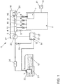
- Fig. 1 shows an internal combustion engine 2 with an injection device. 1
- the internal combustion engine 2 comprises a plurality of combustion chambers 7, wherein the liquid 12 can be supplied via the injection device 1 of each combustion chamber 7 via the outlet 6 (an injection valve).
- the internal combustion engine 2 comprises a device 19 for lambda control of the internal combustion engine 2, wherein the evaluation according to step d) or iii. of the method, a total leakage of the injection device 1 can be determined. Based on the total leakage, a leakage via the at least one outlet 6 can be determined via an evaluation of the lambda control of the internal combustion engine 2.
- the injection device 1 has a volume 3 with an inlet 4, via which the volume 3 with a pressure line 5 and with a first (high-pressure) pump 22 fluid technology is connectable. Via a plurality of outlets 6, the volume 3 can be connected to a plurality of combustion chambers 7 of the internal combustion engine 2.
- the injection device 1 has a first pressure sensor 8 for measuring a pressure 9, 10 in the volume 3.
- step a) of the method a first state 11 of the injection device 1 is established, in which the inlet 4 and the outlets 6 are closed and the volume 3 has a constant volume.
- the volume 3 is completely filled by a liquid 12 intended for injection.
- step b) a first pressure 9 at a first time 13 is measured.
- a second pressure 10 is measured at a later second time 14.
- a first temperature 15 of the liquid 12 in the volume 3 at the first time 13 is determined via a temperature sensor 18.
- a second temperature 16 of the liquid 12 in the volume 3 at the second time 14 is determined.
- An evaluation of a pressure change from the first pressure 9 to the second pressure 10 taking into account the first temperature 15 and the second temperature 16.
- the liquid 12 is conveyed via a second pump 23 from the tank 21 via a filter 25 to the first pump 22. In this area (low pressure area), a second pressure sensor 24 is arranged.
- the volume 3 is filled with the liquid 12 (eg a fuel) via the first pump 22 and pressurized 9, 10. Between the first pump 22 and the volume 3, a pressure line 5 is arranged. Between the pressure line 5 and the volume 3, the inlet 4 is arranged, via which the liquid 12 is supplied to the volume 3.
- the volume 3 is connected via a valve 26 (eg a pressure limiting valve) to a return line 27, via which the liquid 12 is returned from the volume 3 to a tank 21 for the liquid 12 or to a line upstream of the first pump 22 can (low pressure area).
- a valve 26 eg a pressure limiting valve
- the detected leakage can be deposited as an entry in the control device 20. Possibly. a fault message can be generated or the entry can be read out by a diagnostic device.
- the reference to the leakage can be used in a maintenance of the internal combustion engine 2 for troubleshooting. It is further proposed to take into account the physical properties of the fuel in determining the leakage. It should be noted that the liquid 12 (eg fuel) at a constant volume changes its pressure 9, 10 as a function of the present temperature 15, 16.
- a characteristic curve 17 (for the liquid 12 used), which represents the pressure change as a function of the temperature 15, 16 of the liquid 12, can be determined (for example on a test stand) in a leak-free injection device 1.
- the characteristic 17 can be stored in the control device 20 and for step iii. be taken into account.
- the first temperature 15 and the second temperature 16 are measured via a temperature sensor 18.
Landscapes
- Engineering & Computer Science (AREA)
- Chemical & Material Sciences (AREA)
- Combustion & Propulsion (AREA)
- Mechanical Engineering (AREA)
- General Engineering & Computer Science (AREA)
- Physics & Mathematics (AREA)
- General Physics & Mathematics (AREA)
- Combined Controls Of Internal Combustion Engines (AREA)
- Fuel-Injection Apparatus (AREA)
Abstract
Description
- Die Erfindung betrifft ein Verfahren zur Diagnose einer Einspritzvorrichtung für eine Verbrennungskraftmaschine, insbesondere eines Ottomotors oder eines Dieselmotors.
- In direkteinspritzenden Verbrennungskraftmaschinen wird ein Kraftstoff in den Brennraum der Verbrennungskraftmaschine über ein elektrisch betätigtes Einspritzventil in der richtigen Menge und mit einem spezifizierten Spraybild eingespritzt. Die Ausformung dieser Einspritzventile garantiert keine vollständige Dichtheit zwischen dem mit dem Kraftstoff gefüllten Versorgungsrohr (common rail, Druckleitung, im Folgenden als Volumen bezeichnet) und dem Brennraum außerhalb der elektrisch angesteuerten Betätigung. Eine Leckage des Kraftstoffs, durch die Kraftstoff in den Brennraum außerhalb des Verbrennungsvorgangs eintritt, wirkt sich nachteilig im Hinblick auf Schadstoff-Emissionen aus. Der Kraftstoff nimmt unkontrolliert an der Verbrennung teil. Es können dabei Rußpartikel entstehen. Teilweise erfolgt die Umsetzung (Oxidation) des Kraftstoffs im Katalysator oder die Kohlenwasserstoff-Moleküle gelangen durch den Katalysator ungehindert in die Umwelt.
- Wird nach längeren Abstellphasen die Verbrennungskraftmaschine erneut gestartet, drohen im Fall von größeren Leckagen Kraftstoffschläge. Eine weitere Gefahr bei zu niedrigem Kraftstoffdruck ist, dass das Druckgefälle zwischen Brennraum und Versorgungsrohr (Volumen) sich umdreht und das Einspritzventil vom hohen Druck des Gases im Brennraum aufgedrückt wird. Dadurch kann das Einspritzventil verschmutzen. In der Folge der Verschmutzung kann das Spraybild der Kraftstoffeinspritzung negativ beeinflusst werden.
- Aufgabe der vorliegenden Erfindung ist es, die mit Bezug auf den Stand der Technik angeführten Probleme zumindest teilweise zu lösen. Insbesondere soll ein Verfahren angegeben werden, durch das eine Leckage im Kraftstoff-Versorgungsrohr (Volumen) erkannt werden kann.
- Zur Lösung dieser Aufgaben trägt ein Verfahren mit den Merkmalen gemäß Patentanspruch 1 bei. Vorteilhafte Weiterbildungen sind Gegenstand der abhängigen Patentansprüche. Die in den Patentansprüchen einzeln aufgeführten Merkmale sind in technologisch sinnvoller Weise miteinander kombinierbar und können durch erläuternde Sachverhalte aus der Beschreibung und/oder Details aus der Figur ergänzt werden, wobei weitere Ausführungsvarianten der Erfindung aufgezeigt werden.
- Es wird ein Verfahren zur Diagnose einer Einspritzvorrichtung für eine (insbesondere direkteinspritzende) Verbrennungskraftmaschine vorgeschlagen. Die Einspritzvorrichtung weist ein Volumen auf mit mindestens einem Einlass, über den das Volumen (insbesondere über ein Ventil) mit einer Druckleitung (und mit einer (Hochdruck-) Pumpe) fluidtechnisch verbindbar ist, und mindestens einem Auslass, über den das Volumen (insbesondere über ein Ventil) mit mindestens einer Brennkammer der Verbrennungskraftmaschine verbindbar ist. Die Einspritzvorrichtung weist weiter einen ersten Drucksensor zur Messung eines Drucks in dem Volumen auf. Das Verfahren weist zumindest die folgenden Schritte aufweist:
- a) Feststellen eines ersten Zustands der Einspritzvorrichtung, bei dem der mindestens eine Einlass (alle Einlässe) und der mindestens eine Auslass (alle Auslässe) geschlossen sind und das Volumen ein konstantes Volumen aufweist; wobei das Volumen durch eine zur Einspritzung vorgesehene Flüssigkeit vollständig gefüllt ist;
- b) Messen eines ersten Druckes zu einem ersten Zeitpunkt;
- c) Messen eines zweiten Druckes zu einem späteren zweiten Zeitpunkt;
- d) Auswertung einer Druckveränderung von dem ersten Druck zu dem zweiten Druck.
- Das Volumen wird insbesondere über eine erste Pumpe mit der Flüssigkeit (z. B. ein Kraftstoff) gefüllt und unter Druck gesetzt. Zwischen der Pumpe und dem Volumen ist eine Druckleitung angeordnet. Zwischen der Druckleitung und dem Volumen ist insbesondere ein Ventil angeordnet, über das die Flüssigkeit dem Volumen zugeführt wird.
- Das Volumen ist insbesondere über einen Auslass (ggf. mehrere Auslässe) mit mindestens einer Brennkammer (oder mehreren Brennkammern) verbunden. Insbesondere weist jeder Auslass ein Ventil auf, über das die Flüssigkeit dem mindestens einen Brennraum zugeführt wird.
- Insbesondere weist das Volumen ein weiteres Ventil (z. B. ein Druckbegrenzungsventil) in einer Rücklaufleitung auf, über das die Flüssigkeit aus dem Volumen in einen Tank für die Flüssigkeit oder in eine Leitung stromaufwärts der ersten Pumpe zurückgeführt werden kann.
- Der erste Zustand der Einspritzvorrichtung umfasst insbesondere, dass der mindestens eine Einlass und der mindestens eine Auslass geschlossen sind und das Volumen damit ein konstantes Volumen aufweist. Die Flüssigkeit kann bei dem vorliegenden Druck also nicht aus dem Volumen austreten (außer ggf. ungewollt als Leckage).
- Der erste Zustand liegt insbesondere in Phasen ohne gesteuerte Zufuhr und Abfuhr von Flüssigkeit in oder aus dem Volumen vor (z. B. bei Schubabschaltung oder Gasbetrieb der Verbrennungskraftmaschine, elektrischer Betrieb des Kraftfahrzeuges; oder in einer Nachlaufphase, in der ein Steuergerät der Verbrennungskraftmaschine noch wach ist.)
- In derartigen Phasen ist insbesondere die erste Pumpe (ggf. auch eine zweite Pumpe in einem Tank für die Flüssigkeit) abgeschaltet, wobei ein Abfluss von Flüssigkeit aus dem Volumen über die Rücklaufleitung ebenfalls nicht vorliegt.
- Das Volumen ist durch die Flüssigkeit insbesondere vollständig gefüllt. Vollständig heißt hier insbesondere ein Füllgrad des Volumens von mindestens 99 %, bevorzugt von 100 %. Das vollständig gefüllte Volumen befindet sich durch den eingestellten Druck und die vorliegende Temperatur im "fluidischen" Bereich, so dass ein Ausgasen durch das Bilden eines Nassdampfes insbesondere nicht möglich ist. Eine Verdampfung der Flüssigkeit bzw. das Vorliegen von Gas innerhalb des Volumens ist also insbesondere nicht möglich.
- Der Druck innerhalb des Volumens beträgt insbesondere mindestens 80 bar, bevorzugt mindestens 150 bar. Insbesondere beträgt der Druck höchstens 450 bar.
- Die in Schritt d) ausgewertete Druckveränderung kann auf eine Leckage hindeuten. Insbesondere kann über einen Gradienten der Druckveränderung (also Veränderung Druck pro Zeiteinheit) auf das Ausmaß der Leckage (Volumenstrom; also Liter/Minute) geschlossen werden.
- Die festgestellte Leckage kann als Eintrag in einem Steuergerät hinterlegt werden. Ggf. kann eine Störungsmeldung erzeugt oder der Eintrag durch ein Diagnosegerät ausgelesen werden. Der Hinweis auf die Leckage kann bei einer Wartung der Verbrennungskraftmaschine zur Fehlerbehebung genutzt werden.
- Insbesondere umfasst das Verfahren die folgenden zusätzlichen Schritte:
- i. Ermitteln einer ersten Temperatur der Flüssigkeit in dem Volumen zu dem ersten Zeitpunkt;
- ii. Ermitteln einer zweiten Temperatur der Flüssigkeit in dem Volumen zu dem zweiten Zeitpunkt;
- iii. Auswertung einer Druckveränderung von dem ersten Druck zu dem zweiten Druck unter Berücksichtigung der ersten Temperatur und der zweiten Temperatur.
- Schritt iii. erfolgt insbesondere anstatt bzw. als spezielle Ausgestaltung von Schritt d).
- Schritt i. erfolgt insbesondere zeitgleich mit bzw. als spezielle Ausgestaltung von Schritt b). Schritt ii. erfolgt insbesondere zeitgleich mit bzw. als spezielle Ausgestaltung von Schritt c). Ggf. werden Druck und Temperatur innerhalb eines Zeitfensters ermittelt. Der erste bzw. zweite Zeitpunkt umfasst dann z. B. einen Zeitraum von höchstens 20 Sekunden, insbesondere von höchstens 5 Sekunden.
- Insbesondere wird vorgeschlagen, die physikalischen Eigenschaften des Kraftstoffs bei der Ermittlung der Leckage zu berücksichtigen. Dabei ist zu berücksichtigen, dass die Flüssigkeit (z. B. Kraftstoff) bei konstantem Volumen ihren Druck in Abhängigkeit von der vorliegenden Temperatur ändert.
- Die Veränderung des Drucks der Flüssigkeit korreliert mit der Veränderung der Temperatur. Diese Korrelation kann z. B. in einem Leckage-freien bzw. dichten System (z. B. auf einem Prüfstand) für eine Referenzflüssigkeit (oder für den Typ der im Betrieb verwendeten Flüssigkeit) ermittelt und in einem Steuergerät der Verbrennungskraftmaschine (z. B. in Form einer Kennlinie) hinterlegt werden.
- Die zu den betreffenden Zeitpunkten ermittelten Temperaturen können genutzt werden, um die dadurch bewirkte (zulässige) Druckveränderung bestimmen zu können. Eine weitere Abweichung von dieser (zulässigen) Druckveränderung deutet dann auf eine Leckage hin.
- Insbesondere erfolgt die Auswertung der Druckveränderung unter Berücksichtigung einer Ausgasungsaktivität der verwendeten Flüssigkeit.
- Die Ausgasungsaktivität der verwendeten Flüssigkeit kann in der Einspritzvorrichtung ermittelt werden. Ein Verfahren zur Ermittlung der Ausgasungsaktivität durch eine Einspritzvorrichtung ist z. B. aus der
DE 10 2004 062 613 A1 bekannt. - Insbesondere können die physikalischen Eigenschaften der aktuell verwendeten Flüssigkeit auch in der Verbrennungskraftmaschine selber bestimmt werden. Insbesondere kann das Volumen dafür nur teilweise mit der Flüssigkeit gefüllt und die Veränderung des Drucks in Abhängigkeit von der Temperatur bestimmt werden. Damit kann eine Ausgasungsaktivität der Flüssigkeit bestimmt werden, die die Korrelation von Druck und Temperatur der Flüssigkeit auch im flüssigen Zustand der Flüssigkeit maßgeblich bedingt.
- Insbesondere wird eine Kennlinie (für die verwendete Flüssigkeit), die die Druckveränderung in Abhängigkeit von der Temperatur der Flüssigkeit darstellt, in einer leckagefreien Einspritzvorrichtung ermittelt (z. B. auf einem Prüfstand, auf dem z. B. ideale - also vollständig abdichtende - Einspritzventile darstellbar oder zumindest nachbildbar sind). Die Kennlinie kann für Schritt iii. berücksichtigt werden.
- Leckagefrei heißt hier insbesondere, dass eine Leckage in der leckagefreien Einspritzvorrichtung, z. B. in einem definierten Zeitfenster und unter definierten Umgebungsbedingungen, nicht auftritt.
- Gemäß einer ersten Ausgestaltung können die erste Temperatur und die zweite Temperatur mittels eines Temperatursensors gemessen werden.
- Gemäß einer alternativen Ausgestaltung können die erste Temperatur und die zweite Temperatur über ein Wärmeleitmodell bzw. ein Temperaturmodell rechnerisch ermittelt werden.
- Insbesondere wird berücksichtigt, dass der Temperaturverlauf der Flüssigkeit mit dem Temperaturverlauf der Verbrennungskraftmaschine korreliert, an die das Volumen wärmetechnisch gekoppelt ist. Die Verbindung von Volumen und Verbrennungskraftmaschine stellt thermisch betrachtet eine Wärmebrücke dar. Dabei ist der zeitliche Versatz der Temperaturverläufe von Verbrennungskraftmaschine und Volumen zu berücksichtigen.
- Verfahren nach einem der vorhergehenden Patentansprüche, wobei mit der Auswertung nach Schritt d) oder iii. eine Gesamtleckage der Einspritzvorrichtung ermittelt wird.
- Insbesondere kann ausgehend von der Gesamtleckage über eine Auswertung einer Lambdaregelung der Verbrennungskraftmaschine eine Leckage über den mindestens einen Auslass ermittelt werden.
- Insbesondere kann über eine Lambdaregelung der Verbrennungskraftmaschine (also die Messung des Gehalts von Luft im Abgas) festgestellt werden, ob die Flüssigkeit (also Kraftstoff) über den Auslass in die Brennräume gelangt ist.
- Insbesondere erfolgt eine Lambdaregelung für jeden Brennraum. Damit könnte bestimmt werden, über welchen Auslass eine Leckage erfolgt.
- Insbesondere sind neben der Leckage über die Auslässe (also z. B. über ein Einspritzventil für Kraftstoff in den Brennraum) weitere Leckagen möglich. Eine weitere Leckage kann umfassen, dass die Flüssigkeit über den Einlass aus dem Volumen austritt und ggf. über die erste Pumpe in einen Bereich geringeren Druckes (also stromaufwärts der ersten Pumpe) zurückströmt. Diese Art der Leckage ist insbesondere nicht schädlich für die Verbrennungskraftmaschine, solange ein gewisser Volumenstrom nicht überschritten wird.
- Durch die vorstehend beschriebene Ermittlung der Leckage über den Auslass (über die Lambdaregelung) können die Gesamtleckage ermittelt und die (Einzel-)Leckagen zugeordnet werden.
- Es wird weiter eine Einspritzvorrichtung für eine Verbrennungskraftmaschine vorgeschlagen. Die Einspritzvorrichtung weist ein Volumen auf mit mindestens einem Einlass, über den das Volumen mit einer Druckleitung fluidtechnisch verbindbar ist, und mit mindestens einem Auslass, über den das Volumen mit mindestens einer Brennkammer der Verbrennungskraftmaschine verbindbar ist. Die Einspritzvorrichtung weist weiter einen ersten Drucksensor zur Messung eines Drucks in dem Volumen sowie eine Steuervorrichtung (Steuergerät) auf. Die Steuervorrichtung ist zur Durchführung des bereits beschriebenen Verfahrens eingerichtet.
- Weiter wird eine Verbrennungskraftmaschine mit mindestens einer Brennkammer und der bereits beschriebenen Einspritzvorrichtung vorgeschlagen, wobei über die Einspritzvorrichtung der mindestens einen Brennkammer ein Kraftstoff zuführbar ist.
- Insbesondere umfasst die Verbrennungskraftmaschine zusätzlich eine Einrichtung zur Lambdaregelung der Verbrennungskraftmaschine, wobei mit der Auswertung nach Schritt d) oder iii. des Verfahrens eine Gesamtleckage der Einspritzvorrichtung ermittelbar ist. Ausgehend von der Gesamtleckage ist über eine Auswertung der Lambdaregelung der Verbrennungskraftmaschine eine Leckage über den mindestens einen Auslass ermittelbar.
- Die Ausführungen zu dem vorgeschlagenen Verfahren sind auf die vorgeschlagene Einspritzvorrichtung und die Verbrennungskraftmaschine übertragbar und umgekehrt.
- Vorsorglich sei angemerkt, dass die hier verwendeten Zahlwörter ("erste", "zweite", ...) vorrangig (nur) zur Unterscheidung von mehreren gleichartigen Gegenständen, Größen oder Prozessen dienen, also insbesondere keine Abhängigkeit und/oder Reihenfolge dieser Gegenstände, Größen oder Prozesse zueinander zwingend vorgeben. Sollte eine Abhängigkeit und/oder Reihenfolge erforderlich sein, ist dies hier explizit angegeben oder es ergibt sich offensichtlich für den Fachmann beim Studium der konkret beschriebenen Ausgestaltung.
- Die Erfindung sowie das technische Umfeld werden nachfolgend anhand der Figur näher erläutert. Es ist darauf hinzuweisen, dass die Erfindung durch das gezeigte Ausführungsbeispiel nicht beschränkt werden soll. Insbesondere ist es, soweit nicht explizit anders dargestellt, auch möglich, Teilaspekte der in der Figur erläuterten Sachverhalte zu extrahieren und mit anderen Bestandteilen und Erkenntnissen aus der vorliegenden Beschreibung zu kombinieren. Insbesondere ist darauf hinzuweisen, dass die Figur und insbesondere die dargestellten Größenverhältnisse nur schematisch sind.
Fig. 1 zeigt eine Verbrennungskraftmaschine 2 mit einer Einspritzvorrichtung 1. - Die Verbrennungskraftmaschine 2 umfasst mehrere Brennkammern 7, wobei über die Einspritzvorrichtung 1 jeder Brennkammer 7 über den Auslass 6 (ein Einspritzventil) die Flüssigkeit 12 zuführbar ist.
- Die Verbrennungskraftmaschine 2 umfasst eine Einrichtung 19 zur Lambdaregelung der Verbrennungskraftmaschine 2, wobei mit der Auswertung nach Schritt d) oder iii. des Verfahrens eine Gesamtleckage der Einspritzvorrichtung 1 ermittelbar ist. Ausgehend von der Gesamtleckage ist über eine Auswertung der Lambdaregelung der Verbrennungskraftmaschine 2 eine Leckage über den mindestens einen Auslass 6 ermittelbar.
- Die Einspritzvorrichtung 1 weist ein Volumen 3 auf mit einem Einlass 4, über den das Volumen 3 mit einer Druckleitung 5 und mit einer ersten (Hochdruck-)Pumpe 22 fluidtechnisch verbindbar ist. Über eine Mehrzahl von Auslässen 6 ist das Volumen 3 mit einer Mehrzahl von Brennkammern 7 der Verbrennungskraftmaschine 2 verbindbar. Die Einspritzvorrichtung 1 weist einen ersten Drucksensor 8 zur Messung eines Drucks 9, 10 in dem Volumen 3 auf. In Schritt a) des Verfahrens wird ein erster Zustand 11 der Einspritzvorrichtung 1 festgestellt, bei dem der Einlass 4 und die Auslässe 6 geschlossen sind und das Volumen 3 ein konstantes Volumen aufweist. Das Volumen 3 ist durch eine zur Einspritzung vorgesehene Flüssigkeit 12 vollständig gefüllt. In Schritt b) wird ein erster Druck 9 zu einem ersten Zeitpunkt 13 gemessen. In Schritt c) wird ein zweiter Druck 10 zu einem späteren zweiten Zeitpunkt 14 gemessen. In Schritt d) erfolgt eine Auswertung einer Druckveränderung von dem ersten Druck 9 zu dem zweiten Druck 10, z. B. über die Steuervorrichtung 20.
- In einem weiteren Schritt i. wird eine erste Temperatur 15 der Flüssigkeit 12 in dem Volumen 3 zu dem ersten Zeitpunkt 13 über einen Temperatursensor 18 ermittelt. In Schritt ii. wird eine zweite Temperatur 16 der Flüssigkeit 12 in dem Volumen 3 zu dem zweiten Zeitpunkt 14 ermittelt. In Schritt iii. erfolgt eine Auswertung einer Druckveränderung von dem ersten Druck 9 zu dem zweiten Druck 10 unter Berücksichtigung der ersten Temperatur 15 und der zweiten Temperatur 16.
- Die Flüssigkeit 12 wird über eine zweite Pumpe 23 aus dem Tank 21 über einen Filter 25 hin zur ersten Pumpe 22 gefördert. In diesem Bereich (Niederdruckbereich) ist ein zweiter Drucksensor 24 angeordnet. Das Volumen 3 wird über die erste Pumpe 22 mit der Flüssigkeit 12 (z. B. ein Kraftstoff) gefüllt und unter Druck 9, 10 gesetzt. Zwischen der ersten Pumpe 22 und dem Volumen 3 ist eine Druckleitung 5 angeordnet. Zwischen der Druckleitung 5 und dem Volumen 3 ist der Einlass 4 angeordnet, über den die Flüssigkeit 12 dem Volumen 3 zugeführt wird.
- Das Volumen 3 ist über ein Ventil 26 (z. B. ein Druckbegrenzungsventil) mit einer Rücklaufleitung 27 verbunden, über die die Flüssigkeit 12 aus dem Volumen 3 in einen Tank 21 für die Flüssigkeit 12 oder in eine Leitung stromaufwärts der ersten Pumpe 22 zurückgeführt werden kann (Niederdruckbereich).
- Die festgestellte Leckage kann als Eintrag in der Steuervorrichtung 20 hinterlegt werden. Ggf. kann eine Störungsmeldung erzeugt werden oder der Eintrag durch ein Diagnosegerät ausgelesen werden. Der Hinweis auf die Leckage kann bei einer Wartung der Verbrennungskraftmaschine 2 zur Fehlerbehebung genutzt werden. Weiter wird vorgeschlagen, die physikalischen Eigenschaften des Kraftstoffs bei der Ermittlung der Leckage zu berücksichtigen. Dabei ist zu berücksichtigen, dass die Flüssigkeit 12 (z. B. Kraftstoff) bei konstantem Volumen ihren Druck 9, 10 in Abhängigkeit von der vorliegenden Temperatur 15, 16 ändert.
- Eine Kennlinie 17 (für die verwendete Flüssigkeit 12), die die Druckveränderung in Abhängigkeit von der Temperatur 15, 16 der Flüssigkeit 12 darstellt, kann in einer leckagefreien Einspritzvorrichtung 1 ermittelt (z. B. auf einem Prüfstand) werden. Die Kennlinie 17 kann in der Steuervorrichtung 20 gespeichert und für Schritt iii. berücksichtigt werden.
- Die erste Temperatur 15 und die zweite Temperatur 16 werden über einen Temperatursensor 18 gemessen.
-
- 1
- Einspritzvorrichtung
- 2
- Verbrennungskraftmaschine
- 3
- Volumen
- 4
- Einlass
- 5
- Druckleitung
- 6
- Auslass
- 7
- Brennkammer
- 8
- erster Drucksensor
- 9
- erster Druck
- 10
- zweiter Druck
- 11
- erster Zustand
- 12
- Flüssigkeit
- 13
- erster Zeitpunkt
- 14
- zweiter Zeitpunkt
- 15
- erste Temperatur
- 16
- zweite Temperatur
- 17
- Kennlinie
- 18
- Temperatursensor
- 19
- Einrichtung
- 20
- Steuervorrichtung
- 21
- Tank
- 22
- erste Pumpe
- 23
- zweite Pumpe
- 24
- zweiter Drucksensor
- 25
- Filter
- 26
- Ventil
- 27
- Rücklaufleitung
Claims (12)
- Verfahren zur Diagnose einer Einspritzvorrichtung (1) für eine Verbrennungskraftmaschine (2), wobei die Einspritzvorrichtung (1) ein Volumen (3) aufweist mit mindestens einem Einlass (4), über den das Volumen (3) mit einer Druckleitung (5) fluidtechnisch verbindbar ist, und mindestens einem Auslass (6), über den das Volumen (3) mit mindestens einer Brennkammer (7) der Verbrennungskraftmaschine (2) verbindbar ist; wobei die Einspritzvorrichtung (1) weiter einen ersten Drucksensor (8) zur Messung eines Drucks (9, 10) in dem Volumen (3) aufweist; wobei das Verfahren zumindest die folgenden Schritte aufweist:a) Feststellen eines ersten Zustands (11) der Einspritzvorrichtung (1), bei dem der mindestens eine Einlass (4) und der mindestens eine Auslass (6) geschlossen sind und das Volumen (3) ein konstantes Volumen (3) aufweist; wobei das Volumen (3) durch eine zur Einspritzung vorgesehene Flüssigkeit (12) vollständig gefüllt ist;b) Messen eines ersten Druckes (9) zu einem ersten Zeitpunkt (13);c) Messen eines zweiten Druckes (10) zu einem späteren zweiten Zeitpunkt (14);d) Auswertung einer Druckveränderung von dem ersten Druck (9) zu dem zweiten Druck (10).
- Verfahren nach Patentanspruch 1, wobei das Verfahren die folgenden zusätzlichen Schritte umfasst:i. Ermitteln einer ersten Temperatur (15) der Flüssigkeit (12) in dem Volumen (3) zu dem ersten Zeitpunkt (13);ii. Ermitteln einer zweiten Temperatur (16) der Flüssigkeit (12) in dem Volumen (3) zu dem zweiten Zeitpunkt (14);iii. Auswertung einer Druckveränderung von dem ersten Druck (9) zu dem zweiten Druck (10) unter Berücksichtigung der ersten Temperatur (15) und der zweiten Temperatur (16).
- Verfahren nach Patentanspruch 2, wobei die Auswertung der Druckveränderung unter Berücksichtigung einer Ausgasungsaktivität der verwendeten Flüssigkeit (12) erfolgt.
- Verfahren nach Patentanspruch 3, wobei die Ausgasungsaktivität der verwendeten Flüssigkeit (12) in der Einspritzvorrichtung (1) ermittelt wird.
- Verfahren nach einem der vorhergehenden Patentansprüche 2 bis 4, wobei eine Kennlinie (17), die die Druckveränderung in Abhängigkeit von der Temperatur (15, 16) der Flüssigkeit (12) darstellt, in einer leckagefreien Einspritzvorrichtung (1) ermittelt wird; wobei die Kennlinie (17) für Schritt iii. berücksichtigt wird.
- Verfahren nach einem der vorhergehenden Patentansprüche 2 bis 5, wobei die erste Temperatur (15) und die zweite Temperatur (16) über einen Temperatursensor (18) gemessen werden.
- Verfahren nach einem der vorhergehenden Patentansprüche 2 bis 5, wobei die erste Temperatur (15) und die zweite Temperatur (16) über ein Wärmeleitmodell rechnerisch ermittelt werden.
- Verfahren nach einem der vorhergehenden Patentansprüche, wobei mit der Auswertung nach Schritt d) oder iii. eine Gesamtleckage der Einspritzvorrichtung (1) ermittelt wird.
- Verfahren nach Patentanspruch 8, wobei ausgehend von der Gesamtleckage über eine Auswertung einer Lambdaregelung der Verbrennungskraftmaschine (2) eine Leckage über den mindestens einen Auslass (6) ermittelt wird.
- Einspritzvorrichtung (1) für eine Verbrennungskraftmaschine (2), wobei die Einspritzvorrichtung (1) ein Volumen (3) aufweist mit mindestens einem Einlass (4), über den das Volumen (3) mit einer Druckleitung (5) fluidtechnisch verbindbar ist, und mindestens einem Auslass (6), über den das Volumen (3) mit mindestens einer Brennkammer (7) der Verbrennungskraftmaschine (2) verbindbar ist; wobei die Einspritzvorrichtung (1) weiter einen ersten Drucksensor (8) zur Messung eines Drucks (9, 10) in dem Volumen (3) sowie eine Steuervorrichtung (20) aufweist; wobei die Steuervorrichtung (20) zur Durchführung des Verfahrens nach einem der vorhergehenden Patentansprüche eingerichtet ist.
- Verbrennungskraftmaschine (2) mit mindestens einer Brennkammer (7) und einer Einspritzvorrichtung (1) nach Patentanspruch 10, wobei über die Einspritzvorrichtung (1) der mindestens einer Brennkammer (7) ein Kraftstoff zuführbar ist.
- Verbrennungskraftmaschine (2) nach Patentanspruch 11, zusätzlich mit einer Einrichtung (19) zur Lambdaregelung der Verbrennungskraftmaschine (2), wobei mit der Auswertung nach Schritt d) oder iii. des Verfahrens eine Gesamtleckage der Einspritzvorrichtung (1) ermittelbar ist; wobei ausgehend von der Gesamtleckage über eine Auswertung der Lambdaregelung der Verbrennungskraftmaschine (2) eine Leckage über den mindestens einen Auslass (6) ermittelbar ist.
Applications Claiming Priority (1)
| Application Number | Priority Date | Filing Date | Title |
|---|---|---|---|
| DE102018203542.3A DE102018203542A1 (de) | 2018-03-08 | 2018-03-08 | Verfahren zur Diagnose einer Einspritzvorrichtung für eine Verbrennungskraftmaschine |
Publications (2)
| Publication Number | Publication Date |
|---|---|
| EP3536940A1 true EP3536940A1 (de) | 2019-09-11 |
| EP3536940B1 EP3536940B1 (de) | 2021-09-22 |
Family
ID=65686744
Family Applications (1)
| Application Number | Title | Priority Date | Filing Date |
|---|---|---|---|
| EP19160622.7A Active EP3536940B1 (de) | 2018-03-08 | 2019-03-04 | Verfahren zur diagnose einer einspritzvorrichtung für eine verbrennungskraftmaschine |
Country Status (3)
| Country | Link |
|---|---|
| EP (1) | EP3536940B1 (de) |
| CN (1) | CN110242468B (de) |
| DE (1) | DE102018203542A1 (de) |
Families Citing this family (3)
| Publication number | Priority date | Publication date | Assignee | Title |
|---|---|---|---|---|
| CN114646479A (zh) * | 2020-12-18 | 2022-06-21 | 博世汽车服务技术(苏州)有限公司 | 燃料喷射器检测装置、检测系统和检测方法 |
| DE102021200464B4 (de) | 2021-01-19 | 2022-09-15 | Rolls-Royce Solutions GmbH | Verfahren zum Betreiben einer Brennkraftmaschine und Brennkraftmaschine |
| DE102024104552B3 (de) | 2024-02-19 | 2025-03-06 | Dr. Ing. H.C. F. Porsche Aktiengesellschaft | Verfahren zur Prüfung eines Einspritzsystems einer Verbrennungskraftmaschine |
Citations (7)
| Publication number | Priority date | Publication date | Assignee | Title |
|---|---|---|---|---|
| DE19727794C1 (de) * | 1997-06-30 | 1999-01-28 | Siemens Ag | Verfahren zum Überprüfen einer Kraftstoffversorgung |
| DE19908352A1 (de) * | 1999-02-26 | 2000-08-31 | Bosch Gmbh Robert | Kraftstoffeinspritzverfahren für eine Brennkraftmaschine |
| DE102004062613A1 (de) * | 2004-12-24 | 2006-07-06 | Volkswagen Ag | Verfahren und Vorrichtung zur Kraftstoffversorgung von Verbrennungsmotoren |
| DE102007052451A1 (de) * | 2007-11-02 | 2009-05-14 | Continental Automotive Gmbh | Verfahren zum Bestimmen der aktuellen Dauerleckagemenge einer Common-Rail-Einspritzanlage und Einspritzanlage für eine Brennkraftmaschine |
| DE102008060260A1 (de) * | 2008-08-19 | 2010-02-25 | GM Global Technology Operations, Inc., Detroit | Diagnosesysteme und -verfahren für die Hochdruckseite von Kraftstoffsystemen bei Maschinen mit gemeinsamem Kraftstoffverteilerrohr |
| DE102011102260A1 (de) * | 2011-05-23 | 2012-11-29 | Daimler Ag | Kraftstoffeinspritzvorrichtung eines Kraftfahrzeugs |
| DE102012021428A1 (de) * | 2012-10-30 | 2014-04-30 | Audi Ag | Verfahren zum Überprüfen wenigstens einer Komponente in einer Kraftstoffanlage einer Verbrennungskraftmaschine sowie Kraftwagen mit einer Verbrennungkraftmaschine |
Family Cites Families (7)
| Publication number | Priority date | Publication date | Assignee | Title |
|---|---|---|---|---|
| JP4424128B2 (ja) * | 2004-09-10 | 2010-03-03 | 株式会社デンソー | コモンレール式燃料噴射装置 |
| DE102005056153A1 (de) * | 2005-11-23 | 2007-05-24 | Robert Bosch Gmbh | Verfahren und Vorrichtung zur Messung der Einspritzmenge und der Einspritzrate eines Einspritzventils für Flüssigkeiten |
| US7392792B2 (en) * | 2006-08-21 | 2008-07-01 | Caterpillar Inc. | System for dynamically detecting fuel leakage |
| US7762234B2 (en) * | 2008-04-22 | 2010-07-27 | Ford Global Technologies, Llc | Fuel delivery system diagnostics after shut-down |
| EP2295788A1 (de) * | 2009-08-06 | 2011-03-16 | Continental Automotive GmbH | Verfahren und Anordnung zur Bestimmung eines Massenstroms eines Einspritzverfahrens eines Einspritzventils |
| GB2516656A (en) * | 2013-07-29 | 2015-02-04 | Gm Global Tech Operations Inc | A control apparatus for controlling fuel injection into an internal combustion engine |
| DE102015201817B4 (de) * | 2015-02-03 | 2022-05-05 | Ford Global Technologies, Llc | Massenstromverlauf CNG Ventil |
-
2018
- 2018-03-08 DE DE102018203542.3A patent/DE102018203542A1/de not_active Withdrawn
-
2019
- 2019-03-04 EP EP19160622.7A patent/EP3536940B1/de active Active
- 2019-03-08 CN CN201910176261.1A patent/CN110242468B/zh active Active
Patent Citations (7)
| Publication number | Priority date | Publication date | Assignee | Title |
|---|---|---|---|---|
| DE19727794C1 (de) * | 1997-06-30 | 1999-01-28 | Siemens Ag | Verfahren zum Überprüfen einer Kraftstoffversorgung |
| DE19908352A1 (de) * | 1999-02-26 | 2000-08-31 | Bosch Gmbh Robert | Kraftstoffeinspritzverfahren für eine Brennkraftmaschine |
| DE102004062613A1 (de) * | 2004-12-24 | 2006-07-06 | Volkswagen Ag | Verfahren und Vorrichtung zur Kraftstoffversorgung von Verbrennungsmotoren |
| DE102007052451A1 (de) * | 2007-11-02 | 2009-05-14 | Continental Automotive Gmbh | Verfahren zum Bestimmen der aktuellen Dauerleckagemenge einer Common-Rail-Einspritzanlage und Einspritzanlage für eine Brennkraftmaschine |
| DE102008060260A1 (de) * | 2008-08-19 | 2010-02-25 | GM Global Technology Operations, Inc., Detroit | Diagnosesysteme und -verfahren für die Hochdruckseite von Kraftstoffsystemen bei Maschinen mit gemeinsamem Kraftstoffverteilerrohr |
| DE102011102260A1 (de) * | 2011-05-23 | 2012-11-29 | Daimler Ag | Kraftstoffeinspritzvorrichtung eines Kraftfahrzeugs |
| DE102012021428A1 (de) * | 2012-10-30 | 2014-04-30 | Audi Ag | Verfahren zum Überprüfen wenigstens einer Komponente in einer Kraftstoffanlage einer Verbrennungskraftmaschine sowie Kraftwagen mit einer Verbrennungkraftmaschine |
Also Published As
| Publication number | Publication date |
|---|---|
| CN110242468A (zh) | 2019-09-17 |
| CN110242468B (zh) | 2022-09-09 |
| EP3536940B1 (de) | 2021-09-22 |
| DE102018203542A1 (de) | 2019-09-12 |
Similar Documents
| Publication | Publication Date | Title |
|---|---|---|
| DE19513158A1 (de) | Einrichtung zur Erkennung eines Lecks in einem Kraftstoffversorgungssystem | |
| EP3536940A1 (de) | Verfahren zur diagnose einer einspritzvorrichtung für eine verbrennungskraftmaschine | |
| DE102008000691A1 (de) | Verfahren und Vorrichtung zur Überwachung eines Zuluftsystems einer Brennkraftmaschine | |
| EP1180594B1 (de) | Verfahren zur Überprüfung einer Abgasrückführanlage | |
| DE19946874A1 (de) | Diagnose von Stellgliedern und Sensoren in Verbindung mit der Gemischbildung bei Brennkraftmaschinen | |
| DE102011002438A1 (de) | Bestimmung der Beladung eines Partikelfilters | |
| DE102008040633A1 (de) | Verfahren zum Betreiben einer Brennkraftmaschine | |
| DE10215906A1 (de) | Dosierventilüberwachung | |
| EP1204817B1 (de) | Verfahren zur überwachung eines sekundärluftsystems in verbindung mit dem abgassystem eines kraftfahrzeugs | |
| CN109026484A (zh) | 汽车进气道式喷油器在线检测平台的控制系统 | |
| GB2628714A (en) | Method for diagnosing leakage of a water injection system | |
| DE102008041537A1 (de) | Vorrichtung und Verfahren zur Bestimmung von Leckage eines Kraftstoffinjektors | |
| CN113482823B (zh) | 诊断燃油喷射系统故障的方法、装置和具有该装置的汽车 | |
| WO2007042388A1 (de) | Verfahren zur diagnose eines absperrventils | |
| AT516615B1 (de) | Verfahren zur Erkennung einer undichten Stelle in einem Wärmerückgewinnungssystem einer Brennkraftmaschine | |
| WO2021185501A1 (de) | Verfahren zum erkennen von leckagen in einspritzventilen | |
| DE102019220121A1 (de) | Verfahren und Vorrichtung zum Überprüfen der Funktionsfähigkeit einer Erdgas-Brennkraftmaschine | |
| DE102006048498A1 (de) | Fremdgezündete, mit gasförmigem Kraftstoff betreibbare Brennkraftmaschine mit einer Kraftstoffversorgungsanlage und Verfahren zum Betrieb einer Brennkraftmaschine | |
| EP3575581A1 (de) | Verfahren zur ansteuerung eines regelventils | |
| DE102011005172B4 (de) | Verfahren und Steuergerät zur Motor-Fehlerdiagnose | |
| DE102022207728A1 (de) | Verfahren zur Diagnose eines Ventils | |
| DE102004008893A1 (de) | Vorrichtung zur Steuerung einer Brennkraftmaschine | |
| WO2010003780A1 (de) | Verfahren und diagnosegerät zum erkennen einer fehlfunktion an einer einspritzanlage | |
| AT518521B1 (de) | Verfahren zur erkennung einer undichten stelle in einem wärmerückgewinnungssystem | |
| DE102005000853B4 (de) | Verfahren zum Erkennen einer Dichtringextrusion bei einem Injektor |
Legal Events
| Date | Code | Title | Description |
|---|---|---|---|
| PUAI | Public reference made under article 153(3) epc to a published international application that has entered the european phase |
Free format text: ORIGINAL CODE: 0009012 |
|
| STAA | Information on the status of an ep patent application or granted ep patent |
Free format text: STATUS: THE APPLICATION HAS BEEN PUBLISHED |
|
| AK | Designated contracting states |
Kind code of ref document: A1 Designated state(s): AL AT BE BG CH CY CZ DE DK EE ES FI FR GB GR HR HU IE IS IT LI LT LU LV MC MK MT NL NO PL PT RO RS SE SI SK SM TR |
|
| AX | Request for extension of the european patent |
Extension state: BA ME |
|
| STAA | Information on the status of an ep patent application or granted ep patent |
Free format text: STATUS: REQUEST FOR EXAMINATION WAS MADE |
|
| 17P | Request for examination filed |
Effective date: 20200311 |
|
| RBV | Designated contracting states (corrected) |
Designated state(s): AL AT BE BG CH CY CZ DE DK EE ES FI FR GB GR HR HU IE IS IT LI LT LU LV MC MK MT NL NO PL PT RO RS SE SI SK SM TR |
|
| STAA | Information on the status of an ep patent application or granted ep patent |
Free format text: STATUS: EXAMINATION IS IN PROGRESS |
|
| 17Q | First examination report despatched |
Effective date: 20200527 |
|
| GRAP | Despatch of communication of intention to grant a patent |
Free format text: ORIGINAL CODE: EPIDOSNIGR1 |
|
| STAA | Information on the status of an ep patent application or granted ep patent |
Free format text: STATUS: GRANT OF PATENT IS INTENDED |
|
| INTG | Intention to grant announced |
Effective date: 20210618 |
|
| GRAS | Grant fee paid |
Free format text: ORIGINAL CODE: EPIDOSNIGR3 |
|
| GRAA | (expected) grant |
Free format text: ORIGINAL CODE: 0009210 |
|
| STAA | Information on the status of an ep patent application or granted ep patent |
Free format text: STATUS: THE PATENT HAS BEEN GRANTED |
|
| AK | Designated contracting states |
Kind code of ref document: B1 Designated state(s): AL AT BE BG CH CY CZ DE DK EE ES FI FR GB GR HR HU IE IS IT LI LT LU LV MC MK MT NL NO PL PT RO RS SE SI SK SM TR |
|
| REG | Reference to a national code |
Ref country code: GB Ref legal event code: FG4D Free format text: NOT ENGLISH |
|
| REG | Reference to a national code |
Ref country code: IE Ref legal event code: FG4D Free format text: LANGUAGE OF EP DOCUMENT: GERMAN |
|
| REG | Reference to a national code |
Ref country code: DE Ref legal event code: R096 Ref document number: 502019002315 Country of ref document: DE |
|
| REG | Reference to a national code |
Ref country code: CH Ref legal event code: EP Ref country code: AT Ref legal event code: REF Ref document number: 1432505 Country of ref document: AT Kind code of ref document: T Effective date: 20211015 |
|
| REG | Reference to a national code |
Ref country code: LT Ref legal event code: MG9D |
|
| REG | Reference to a national code |
Ref country code: NL Ref legal event code: MP Effective date: 20210922 |
|
| PG25 | Lapsed in a contracting state [announced via postgrant information from national office to epo] |
Ref country code: SE Free format text: LAPSE BECAUSE OF FAILURE TO SUBMIT A TRANSLATION OF THE DESCRIPTION OR TO PAY THE FEE WITHIN THE PRESCRIBED TIME-LIMIT Effective date: 20210922 Ref country code: RS Free format text: LAPSE BECAUSE OF FAILURE TO SUBMIT A TRANSLATION OF THE DESCRIPTION OR TO PAY THE FEE WITHIN THE PRESCRIBED TIME-LIMIT Effective date: 20210922 Ref country code: FI Free format text: LAPSE BECAUSE OF FAILURE TO SUBMIT A TRANSLATION OF THE DESCRIPTION OR TO PAY THE FEE WITHIN THE PRESCRIBED TIME-LIMIT Effective date: 20210922 Ref country code: HR Free format text: LAPSE BECAUSE OF FAILURE TO SUBMIT A TRANSLATION OF THE DESCRIPTION OR TO PAY THE FEE WITHIN THE PRESCRIBED TIME-LIMIT Effective date: 20210922 Ref country code: NO Free format text: LAPSE BECAUSE OF FAILURE TO SUBMIT A TRANSLATION OF THE DESCRIPTION OR TO PAY THE FEE WITHIN THE PRESCRIBED TIME-LIMIT Effective date: 20211222 Ref country code: LT Free format text: LAPSE BECAUSE OF FAILURE TO SUBMIT A TRANSLATION OF THE DESCRIPTION OR TO PAY THE FEE WITHIN THE PRESCRIBED TIME-LIMIT Effective date: 20210922 Ref country code: BG Free format text: LAPSE BECAUSE OF FAILURE TO SUBMIT A TRANSLATION OF THE DESCRIPTION OR TO PAY THE FEE WITHIN THE PRESCRIBED TIME-LIMIT Effective date: 20211222 |
|
| PG25 | Lapsed in a contracting state [announced via postgrant information from national office to epo] |
Ref country code: LV Free format text: LAPSE BECAUSE OF FAILURE TO SUBMIT A TRANSLATION OF THE DESCRIPTION OR TO PAY THE FEE WITHIN THE PRESCRIBED TIME-LIMIT Effective date: 20210922 Ref country code: GR Free format text: LAPSE BECAUSE OF FAILURE TO SUBMIT A TRANSLATION OF THE DESCRIPTION OR TO PAY THE FEE WITHIN THE PRESCRIBED TIME-LIMIT Effective date: 20211223 |
|
| PG25 | Lapsed in a contracting state [announced via postgrant information from national office to epo] |
Ref country code: IS Free format text: LAPSE BECAUSE OF FAILURE TO SUBMIT A TRANSLATION OF THE DESCRIPTION OR TO PAY THE FEE WITHIN THE PRESCRIBED TIME-LIMIT Effective date: 20220122 Ref country code: SK Free format text: LAPSE BECAUSE OF FAILURE TO SUBMIT A TRANSLATION OF THE DESCRIPTION OR TO PAY THE FEE WITHIN THE PRESCRIBED TIME-LIMIT Effective date: 20210922 Ref country code: RO Free format text: LAPSE BECAUSE OF FAILURE TO SUBMIT A TRANSLATION OF THE DESCRIPTION OR TO PAY THE FEE WITHIN THE PRESCRIBED TIME-LIMIT Effective date: 20210922 Ref country code: PT Free format text: LAPSE BECAUSE OF FAILURE TO SUBMIT A TRANSLATION OF THE DESCRIPTION OR TO PAY THE FEE WITHIN THE PRESCRIBED TIME-LIMIT Effective date: 20220124 Ref country code: PL Free format text: LAPSE BECAUSE OF FAILURE TO SUBMIT A TRANSLATION OF THE DESCRIPTION OR TO PAY THE FEE WITHIN THE PRESCRIBED TIME-LIMIT Effective date: 20210922 Ref country code: NL Free format text: LAPSE BECAUSE OF FAILURE TO SUBMIT A TRANSLATION OF THE DESCRIPTION OR TO PAY THE FEE WITHIN THE PRESCRIBED TIME-LIMIT Effective date: 20210922 Ref country code: ES Free format text: LAPSE BECAUSE OF FAILURE TO SUBMIT A TRANSLATION OF THE DESCRIPTION OR TO PAY THE FEE WITHIN THE PRESCRIBED TIME-LIMIT Effective date: 20210922 Ref country code: EE Free format text: LAPSE BECAUSE OF FAILURE TO SUBMIT A TRANSLATION OF THE DESCRIPTION OR TO PAY THE FEE WITHIN THE PRESCRIBED TIME-LIMIT Effective date: 20210922 Ref country code: CZ Free format text: LAPSE BECAUSE OF FAILURE TO SUBMIT A TRANSLATION OF THE DESCRIPTION OR TO PAY THE FEE WITHIN THE PRESCRIBED TIME-LIMIT Effective date: 20210922 Ref country code: AL Free format text: LAPSE BECAUSE OF FAILURE TO SUBMIT A TRANSLATION OF THE DESCRIPTION OR TO PAY THE FEE WITHIN THE PRESCRIBED TIME-LIMIT Effective date: 20210922 |
|
| REG | Reference to a national code |
Ref country code: DE Ref legal event code: R097 Ref document number: 502019002315 Country of ref document: DE |
|
| PG25 | Lapsed in a contracting state [announced via postgrant information from national office to epo] |
Ref country code: DK Free format text: LAPSE BECAUSE OF FAILURE TO SUBMIT A TRANSLATION OF THE DESCRIPTION OR TO PAY THE FEE WITHIN THE PRESCRIBED TIME-LIMIT Effective date: 20210922 |
|
| PLBE | No opposition filed within time limit |
Free format text: ORIGINAL CODE: 0009261 |
|
| STAA | Information on the status of an ep patent application or granted ep patent |
Free format text: STATUS: NO OPPOSITION FILED WITHIN TIME LIMIT |
|
| 26N | No opposition filed |
Effective date: 20220623 |
|
| PG25 | Lapsed in a contracting state [announced via postgrant information from national office to epo] |
Ref country code: MC Free format text: LAPSE BECAUSE OF FAILURE TO SUBMIT A TRANSLATION OF THE DESCRIPTION OR TO PAY THE FEE WITHIN THE PRESCRIBED TIME-LIMIT Effective date: 20210922 |
|
| REG | Reference to a national code |
Ref country code: CH Ref legal event code: PL |
|
| PG25 | Lapsed in a contracting state [announced via postgrant information from national office to epo] |
Ref country code: SI Free format text: LAPSE BECAUSE OF FAILURE TO SUBMIT A TRANSLATION OF THE DESCRIPTION OR TO PAY THE FEE WITHIN THE PRESCRIBED TIME-LIMIT Effective date: 20210922 |
|
| REG | Reference to a national code |
Ref country code: BE Ref legal event code: MM Effective date: 20220331 |
|
| PG25 | Lapsed in a contracting state [announced via postgrant information from national office to epo] |
Ref country code: LU Free format text: LAPSE BECAUSE OF NON-PAYMENT OF DUE FEES Effective date: 20220304 Ref country code: LI Free format text: LAPSE BECAUSE OF NON-PAYMENT OF DUE FEES Effective date: 20220331 Ref country code: IT Free format text: LAPSE BECAUSE OF FAILURE TO SUBMIT A TRANSLATION OF THE DESCRIPTION OR TO PAY THE FEE WITHIN THE PRESCRIBED TIME-LIMIT Effective date: 20210922 Ref country code: IE Free format text: LAPSE BECAUSE OF NON-PAYMENT OF DUE FEES Effective date: 20220304 Ref country code: CH Free format text: LAPSE BECAUSE OF NON-PAYMENT OF DUE FEES Effective date: 20220331 |
|
| PG25 | Lapsed in a contracting state [announced via postgrant information from national office to epo] |
Ref country code: BE Free format text: LAPSE BECAUSE OF NON-PAYMENT OF DUE FEES Effective date: 20220331 |
|
| P01 | Opt-out of the competence of the unified patent court (upc) registered |
Effective date: 20230523 |
|
| PG25 | Lapsed in a contracting state [announced via postgrant information from national office to epo] |
Ref country code: SM Free format text: LAPSE BECAUSE OF FAILURE TO SUBMIT A TRANSLATION OF THE DESCRIPTION OR TO PAY THE FEE WITHIN THE PRESCRIBED TIME-LIMIT Effective date: 20210922 Ref country code: MK Free format text: LAPSE BECAUSE OF FAILURE TO SUBMIT A TRANSLATION OF THE DESCRIPTION OR TO PAY THE FEE WITHIN THE PRESCRIBED TIME-LIMIT Effective date: 20210922 Ref country code: CY Free format text: LAPSE BECAUSE OF FAILURE TO SUBMIT A TRANSLATION OF THE DESCRIPTION OR TO PAY THE FEE WITHIN THE PRESCRIBED TIME-LIMIT Effective date: 20210922 |
|
| PG25 | Lapsed in a contracting state [announced via postgrant information from national office to epo] |
Ref country code: HU Free format text: LAPSE BECAUSE OF FAILURE TO SUBMIT A TRANSLATION OF THE DESCRIPTION OR TO PAY THE FEE WITHIN THE PRESCRIBED TIME-LIMIT; INVALID AB INITIO Effective date: 20190304 |
|
| PG25 | Lapsed in a contracting state [announced via postgrant information from national office to epo] |
Ref country code: MT Free format text: LAPSE BECAUSE OF FAILURE TO SUBMIT A TRANSLATION OF THE DESCRIPTION OR TO PAY THE FEE WITHIN THE PRESCRIBED TIME-LIMIT Effective date: 20210922 |
|
| REG | Reference to a national code |
Ref country code: AT Ref legal event code: MM01 Ref document number: 1432505 Country of ref document: AT Kind code of ref document: T Effective date: 20240304 |
|
| PG25 | Lapsed in a contracting state [announced via postgrant information from national office to epo] |
Ref country code: AT Free format text: LAPSE BECAUSE OF NON-PAYMENT OF DUE FEES Effective date: 20240304 |
|
| PG25 | Lapsed in a contracting state [announced via postgrant information from national office to epo] |
Ref country code: TR Free format text: LAPSE BECAUSE OF FAILURE TO SUBMIT A TRANSLATION OF THE DESCRIPTION OR TO PAY THE FEE WITHIN THE PRESCRIBED TIME-LIMIT Effective date: 20210922 |
|
| PGFP | Annual fee paid to national office [announced via postgrant information from national office to epo] |
Ref country code: GB Payment date: 20260323 Year of fee payment: 8 |
|
| PGFP | Annual fee paid to national office [announced via postgrant information from national office to epo] |
Ref country code: DE Payment date: 20260331 Year of fee payment: 8 |
|
| PGFP | Annual fee paid to national office [announced via postgrant information from national office to epo] |
Ref country code: AT Payment date: 20260410 Year of fee payment: 5 |
|
| PGFP | Annual fee paid to national office [announced via postgrant information from national office to epo] |
Ref country code: FR Payment date: 20260323 Year of fee payment: 8 |