EP3536935A1 - A throttle valve with the possibility of adjusting an intermediate position of partial opening and relative method to adjust the intermediate position - Google Patents
A throttle valve with the possibility of adjusting an intermediate position of partial opening and relative method to adjust the intermediate position Download PDFInfo
- Publication number
- EP3536935A1 EP3536935A1 EP19161422.1A EP19161422A EP3536935A1 EP 3536935 A1 EP3536935 A1 EP 3536935A1 EP 19161422 A EP19161422 A EP 19161422A EP 3536935 A1 EP3536935 A1 EP 3536935A1
- Authority
- EP
- European Patent Office
- Prior art keywords
- additional component
- throttle valve
- main component
- shaft
- end gear
- Prior art date
- Legal status (The legal status is an assumption and is not a legal conclusion. Google has not performed a legal analysis and makes no representation as to the accuracy of the status listed.)
- Granted
Links
Images





Classifications
-
- F—MECHANICAL ENGINEERING; LIGHTING; HEATING; WEAPONS; BLASTING
- F02—COMBUSTION ENGINES; HOT-GAS OR COMBUSTION-PRODUCT ENGINE PLANTS
- F02D—CONTROLLING COMBUSTION ENGINES
- F02D9/00—Controlling engines by throttling air or fuel-and-air induction conduits or exhaust conduits
- F02D9/08—Throttle valves specially adapted therefor; Arrangements of such valves in conduits
- F02D9/10—Throttle valves specially adapted therefor; Arrangements of such valves in conduits having pivotally-mounted flaps
- F02D9/1065—Mechanical control linkage between an actuator and the flap, e.g. including levers, gears, springs, clutches, limit stops of the like
-
- F—MECHANICAL ENGINEERING; LIGHTING; HEATING; WEAPONS; BLASTING
- F02—COMBUSTION ENGINES; HOT-GAS OR COMBUSTION-PRODUCT ENGINE PLANTS
- F02D—CONTROLLING COMBUSTION ENGINES
- F02D9/00—Controlling engines by throttling air or fuel-and-air induction conduits or exhaust conduits
- F02D9/08—Throttle valves specially adapted therefor; Arrangements of such valves in conduits
- F02D9/10—Throttle valves specially adapted therefor; Arrangements of such valves in conduits having pivotally-mounted flaps
- F02D9/107—Manufacturing or mounting details
-
- F—MECHANICAL ENGINEERING; LIGHTING; HEATING; WEAPONS; BLASTING
- F16—ENGINEERING ELEMENTS AND UNITS; GENERAL MEASURES FOR PRODUCING AND MAINTAINING EFFECTIVE FUNCTIONING OF MACHINES OR INSTALLATIONS; THERMAL INSULATION IN GENERAL
- F16K—VALVES; TAPS; COCKS; ACTUATING-FLOATS; DEVICES FOR VENTING OR AERATING
- F16K1/00—Lift valves or globe valves, i.e. cut-off apparatus with closure members having at least a component of their opening and closing motion perpendicular to the closing faces
- F16K1/16—Lift valves or globe valves, i.e. cut-off apparatus with closure members having at least a component of their opening and closing motion perpendicular to the closing faces with pivoted closure-members
- F16K1/18—Lift valves or globe valves, i.e. cut-off apparatus with closure members having at least a component of their opening and closing motion perpendicular to the closing faces with pivoted closure-members with pivoted discs or flaps
- F16K1/22—Lift valves or globe valves, i.e. cut-off apparatus with closure members having at least a component of their opening and closing motion perpendicular to the closing faces with pivoted closure-members with pivoted discs or flaps with axis of rotation crossing the valve member, e.g. butterfly valves
- F16K1/221—Lift valves or globe valves, i.e. cut-off apparatus with closure members having at least a component of their opening and closing motion perpendicular to the closing faces with pivoted closure-members with pivoted discs or flaps with axis of rotation crossing the valve member, e.g. butterfly valves specially adapted operating means therefor
-
- F—MECHANICAL ENGINEERING; LIGHTING; HEATING; WEAPONS; BLASTING
- F16—ENGINEERING ELEMENTS AND UNITS; GENERAL MEASURES FOR PRODUCING AND MAINTAINING EFFECTIVE FUNCTIONING OF MACHINES OR INSTALLATIONS; THERMAL INSULATION IN GENERAL
- F16K—VALVES; TAPS; COCKS; ACTUATING-FLOATS; DEVICES FOR VENTING OR AERATING
- F16K31/00—Actuating devices; Operating means; Releasing devices
- F16K31/02—Actuating devices; Operating means; Releasing devices electric; magnetic
- F16K31/04—Actuating devices; Operating means; Releasing devices electric; magnetic using a motor
- F16K31/041—Actuating devices; Operating means; Releasing devices electric; magnetic using a motor for rotating valves
-
- F—MECHANICAL ENGINEERING; LIGHTING; HEATING; WEAPONS; BLASTING
- F16—ENGINEERING ELEMENTS AND UNITS; GENERAL MEASURES FOR PRODUCING AND MAINTAINING EFFECTIVE FUNCTIONING OF MACHINES OR INSTALLATIONS; THERMAL INSULATION IN GENERAL
- F16K—VALVES; TAPS; COCKS; ACTUATING-FLOATS; DEVICES FOR VENTING OR AERATING
- F16K31/00—Actuating devices; Operating means; Releasing devices
- F16K31/44—Mechanical actuating means
- F16K31/53—Mechanical actuating means with toothed gearing
- F16K31/535—Mechanical actuating means with toothed gearing for rotating valves
-
- F—MECHANICAL ENGINEERING; LIGHTING; HEATING; WEAPONS; BLASTING
- F02—COMBUSTION ENGINES; HOT-GAS OR COMBUSTION-PRODUCT ENGINE PLANTS
- F02B—INTERNAL-COMBUSTION PISTON ENGINES; COMBUSTION ENGINES IN GENERAL
- F02B3/00—Engines characterised by air compression and subsequent fuel addition
- F02B3/06—Engines characterised by air compression and subsequent fuel addition with compression ignition
-
- F—MECHANICAL ENGINEERING; LIGHTING; HEATING; WEAPONS; BLASTING
- F02—COMBUSTION ENGINES; HOT-GAS OR COMBUSTION-PRODUCT ENGINE PLANTS
- F02D—CONTROLLING COMBUSTION ENGINES
- F02D11/00—Arrangements for, or adaptations to, non-automatic engine control initiation means, e.g. operator initiated
- F02D11/06—Arrangements for, or adaptations to, non-automatic engine control initiation means, e.g. operator initiated characterised by non-mechanical control linkages, e.g. fluid control linkages or by control linkages with power drive or assistance
- F02D11/10—Arrangements for, or adaptations to, non-automatic engine control initiation means, e.g. operator initiated characterised by non-mechanical control linkages, e.g. fluid control linkages or by control linkages with power drive or assistance of the electric type
- F02D11/107—Safety-related aspects
-
- F—MECHANICAL ENGINEERING; LIGHTING; HEATING; WEAPONS; BLASTING
- F02—COMBUSTION ENGINES; HOT-GAS OR COMBUSTION-PRODUCT ENGINE PLANTS
- F02D—CONTROLLING COMBUSTION ENGINES
- F02D9/00—Controlling engines by throttling air or fuel-and-air induction conduits or exhaust conduits
- F02D9/02—Controlling engines by throttling air or fuel-and-air induction conduits or exhaust conduits concerning induction conduits
- F02D2009/0201—Arrangements; Control features; Details thereof
- F02D2009/0269—Throttle closing springs; Acting of throttle closing springs on the throttle shaft
-
- F—MECHANICAL ENGINEERING; LIGHTING; HEATING; WEAPONS; BLASTING
- F02—COMBUSTION ENGINES; HOT-GAS OR COMBUSTION-PRODUCT ENGINE PLANTS
- F02D—CONTROLLING COMBUSTION ENGINES
- F02D9/00—Controlling engines by throttling air or fuel-and-air induction conduits or exhaust conduits
- F02D9/02—Controlling engines by throttling air or fuel-and-air induction conduits or exhaust conduits concerning induction conduits
- F02D2009/0201—Arrangements; Control features; Details thereof
- F02D2009/0277—Fail-safe mechanisms, e.g. with limp-home feature, to close throttle if actuator fails, or if control cable sticks or breaks
-
- F—MECHANICAL ENGINEERING; LIGHTING; HEATING; WEAPONS; BLASTING
- F02—COMBUSTION ENGINES; HOT-GAS OR COMBUSTION-PRODUCT ENGINE PLANTS
- F02D—CONTROLLING COMBUSTION ENGINES
- F02D9/00—Controlling engines by throttling air or fuel-and-air induction conduits or exhaust conduits
- F02D9/08—Throttle valves specially adapted therefor; Arrangements of such valves in conduits
- F02D9/10—Throttle valves specially adapted therefor; Arrangements of such valves in conduits having pivotally-mounted flaps
- F02D9/1035—Details of the valve housing
- F02D9/105—Details of the valve housing having a throttle position sensor
Definitions
- the present invention relates to a throttle valve and relative method to adjust an intermediate position of partial opening.
- the present invention can advantageously be applied to a suction throttle valve for an internal combustion engine with the possibility of adjusting the limp-home position (corresponding to an intermediate position of partial opening between a limit position of complete closing and a limit position of complete opening).
- a throttle valve is normally comprised, in internal combustion engines supplied by petrol, which regulates the air flow rate supplied to the cylinders; typically, the throttle valve has a valve body housing a valve seat engaged by a throttle plate, which is fitted onto a shaft to rotate between an opening position and a closing position due to the action of an electric motor coupled to the shaft by means of a gear transmission.
- a position sensor is associated with the shaft supporting the throttle valve, which is designed to detect the angular position of the shaft, and thus of the throttle valve, to enable a control unit to control the electric motor in feedback, which determines the position of the throttle valve.
- the throttle valve comprises a spiral return spring, which is mounted coaxial to the shaft and it is mechanically coupled to the shaft to exert a torque on the shaft, which tends to bring the shaft from a position of maximum opening towards an intermediate position of partial opening (also called limp-home position).
- the throttle valve comprises a spiral countering spring, which is mounted coaxial to the shaft and it is mechanically coupled to the shaft to exert a torque on the shaft, which tends to bring the shaft from a position of complete closing towards the limp-home position; the limp-home position is defined by a striking body, which defines an end stop for the countering spring.
- the torque generated by the countering spring is greater than the torque generated by the return spring; for this reason, when the electric motor is deactivated, the shaft is arranged in the limp-home position and the electric motor must then generate an engine torque both to bring the shaft into the position of maximum opening and to bring the shaft into the position of complete closing.
- Patent applications US2006231072A1 , EP1099839A2 and DE10202096A1 describe throttle valves provided with a spiral return spring, which is mounted coaxial to the shaft and it is mechanically coupled to the shaft to exert a torque on the shaft, which tends to bring the shaft from a position of maximum opening towards the limp-home position.
- the effective limp-home position (and thus the effective limp-home air flow rate, which crosses the throttle valve in the limp-home position) is subject to various structural tolerances, which make the effective limp-home position generally relatively uncertain (overall the tolerance can reach ⁇ 20-25%); in other words, the structural tolerance on the limp-home position (limp-home air flow rate) is relatively great.
- the throttle valve 1 comprises a metal valve body 2 in which an intake duct 4 is obtained, through which the air sucked in from the internal combustion heat engine passes.
- the intake duct 4 is engaged by a throttle plate 5, which moves between an opening position and a closing position of the intake duct 4 due to the effect of the action of an electric motor 3 (shown schematically in Figure 2 ).
- the throttle plate 5 is fitted onto a metal shaft 6, which is mounted rotatably about a longitudinal rotation axis 7 to rotate between the opening position and the closing position under the control of the electric motor 3, which is coupled to the shaft 6 by means of a gear transmission 8 (only partially shown in Figure 4 ).
- the electric motor 3 (not shown) is arranged in a tubular housing 9 arranged by the side of the intake duct 4 and it has a shaft, which is mechanically connected to the shaft 6 by means of the gear transmission 8.
- the gear transmission 8 comprises a cogwheel (not shown), which is angularly integral with the shaft of the electric motor 3, an end gear 10, which is angularly integral with the shaft 6, and an intermediate cogwheel (not shown), which is mounted idle on the valve body 2 and interposed between the cogwheel of the electric motor 3 and the end gear 10.
- the intermediate cogwheel (not shown) has a first series of teeth coupled to the cogwheel of the electric motor 3 and a second series of teeth coupled to the end gear 10; the diameter of the first series of teeth is different from the diameter of the second series of teeth, so the intermediate cogwheel (not shown) determines a non-unitary gear ratio.
- the end gear 10 comprises a central cylindrical body 11, which is fitted onto the shaft 6 (i.e. it is angularly integral with the shaft 6) and is provided with a toothed segment 12 provided with a series of teeth coupled to the intermediate cogwheel (not shown).
- the intermediate cogwheel (not shown) and the end gear 10 are normally made of a plastic material, while the cogwheel (not shown) of the electric motor 3 is normally made of sintered steel.
- the end gear 10 is made of a plastic material and it is overmoulded around the shaft 6, which is normally made of a metal material (for example, steel or aluminium).
- the assembly of the throttle plate 5, the shaft 6 and the end gear 10 make up a movable apparatus, which, in use, rotates about the rotation axis 7 under the control of the electric motor 3.
- the gear transmission 8 is arranged in a chamber of the valve body 2, which is sealed by a removable cover and made of a plastic material.
- the throttle valve comprises an inductive position sensor of the "contactless type" (not shown), which is coupled to the shaft 6 and designed to detect the angular position of the shaft 6 and, thus, of the throttle plate 5, to enable a feedback control of the position of the throttle plate 5.
- the position sensor could be of the type described in patent US6236199B1 and thus comprise a rotor, which is angularly integral with the shaft 6 (in particular with the end gear 10) and a stator supported by the cover and arranged, in use, facing the rotor.
- the position sensor (not shown) could be of the magnetostrictive type and thus comprise a permanent magnet integral with the shaft 6 (in particular with the end gear 10).
- a thread-forming minimum screw is comprised, which is screwed into a hole 13 (shown in Figure 1 ) obtained through the valve body 2 and cooperating with the toothed segment 12 of the end gear 10; when the shaft 6 is brought by the action of the electric motor 3 into the closing position, the rotation of the shaft 6 is not stopped by the impact between the throttle plate 5 and the walls of the intake duct 4, but it is stopped by the impact of the toothed segment 12 of the end gear 10 against the minimum screw.
- a potential impact between the throttle plate 5 and the walls of the intake duct 4 could determine an interlocking of the throttle plate 5 with the walls of the intake duct 4 with a consequent jamming of the throttle valve 1.
- the throttle valve 1 comprises a return spring 14, which is a spiral torsion spring (i.e. the spring deforms according to a circular displacement, generating a resistive torque) and it tends to rotate the shaft 6 in a closing direction with a movement, which brings the throttle plate 5 towards the closing position.
- the throttle valve 1 further comprises a countering spring 15, which is a spiral torsion spring (i.e. the spring deforms according to a circular displacement, generating a resistive torque) and it tends to rotate the shaft 6 in an opening direction, opposite the closing direction with a movement, which brings the throttle plate 5 towards an opening position.
- the return spring 14 generates a lower torque than the torque generated by the countering spring 15, therefore, in general, the combination of the effects of the springs 14 and 15 tends to rotate the shaft 6 in the opening direction and towards an opening position of the throttle plate 5.
- a striking element 16 is comprised (shown in Figures 3 and 8 ), which is obtained on the valve body 2 (i.e. it is a part of the valve body 2) and it forms a stop for the rotation movement impressed by the countering spring 15 (i.e. the countering spring 15 cannot rotate the shaft 6 beyond the limit position established by the striking element 16), defining an intermediate position of partial opening (between a limit position of complete closing and a limit position of complete opening) or limp-home position.
- the engine torque generated by the electric motor 3 is capable of rotating the shaft 6 (and thus the throttle plate 5) into a position of complete closing against the torque generated by the countering spring 15 and it is capable of rotating the shaft 6 (and thus the throttle plate 5) into a position of maximum opening against the torque generated by the return spring 14.
- the return spring 14 is coaxial to the rotation axis 7 and it is arranged about the cylindrical body 11 of the end gear 10 (i.e. it surrounds the cylindrical body 11 of the end gear 10).
- the countering spring 15 is coaxial to the rotation axis 7 and it is arranged inside the cylindrical body 11 of the end gear 10 (and thus it is mounted in the cylindrical body 11 of the end gear 10).
- the return spring 14 has one end 17 resting on a wall of the end gear 10 (in particular, on a side wall of the toothed segment 12, as shown in Figure 4 ) to push on the end gear 10, and one end 18 opposite the end 17, which is inserted in a seat 19 (shown in Figure 3 ) obtained in the valve body 2 to be constrained with the valve body 2 (i.e. to "use force" on the valve body 2 so as to push the end gear 10, and thus the shaft 6 carrying the throttle plate 5, towards the closing position).
- the countering spring 15 is mounted on the end gear 10; in particular, one end 20 of the countering spring 15 is integral with the end gear 10 (i.e. it is inserted in a seat of the end gear 10) and the end 21 of the countering spring 15 opposite the end 20 is arranged so that the end gear 10, in the rotating movement thereof, from the position of complete closing to the position of opening, impacts against it, thus stopping in the limp-home position.
- the end 21 of the countering spring is fixed on the striking element 16 during the movement of the shaft 6 between the complete closing and limp-home positions.
- the return spring 14 During the movement from the limp-home position to the position of complete closing, the return spring 14 generates a torque, which assists the movement of the shaft 6; thus, while the electric motor 3 actuates this movement, it is assisted by the action of the return spring 14.
- the return spring 14 generates a torque, which opposes the movement of the shaft 6; thus, during this movement, the electric motor 3 must also overcome the action generated by the return spring 14.
- the return spring 14 always generates a torque aimed at closing the throttle plate 5: in the case of a closing movement, the return spring 14 generates a favourable torque; in the case of an opening movement, the return spring 14 generates an opposite torque.
- the shaft 6 (thus the throttle plate 5) is arranged in the limp-home position: in fact, to move from the limp-home position established by the striking element 16 it would be necessary to overcome the elastic force generated by the return spring 14 (to go from the limp-home position towards the position of complete opening) or it would be necessary to overcome the elastic force generated by the countering spring 15 (to go from the limp-home position towards the position of complete closing) and, to overcome the elastic force generated by the springs 14 and 15 the action of the electric motor 3 is needed.
- the end gear 10 comprises a main component 22, on which the cylindrical body 11 and the toothed segment 12 are obtained, and an additional component 23, which is coupled and heat-welded (using subsequently described methods) to the main component 22.
- the additional component 23 comprises two coupling elements 24 and 25, which make up the two tines of a fork (illustrated better in Figure 9 ) inside which the end 21 of the countering spring is arranged (as illustrated in Figure 7 ).
- the coupling element 25 is arranged at the striking element 16 and the end 21 of the countering spring 15 is resting on the coupling element 25 in the limp-home position.
- the additional component 23 has a central body 26 with the shape of a disc, from which the two coupling elements 24 and 25 project, facing axially (i.e. parallel to the rotation axis 7).
- the central body 26 of the additional component 23 has an annular groove 27, which, as described better below, identifies the connection area by means of heat-welding between the additional component 23 and the main component 22; in other words, the additional component 23 is constrained to the main component 22 by means of an annular heat-welding, which develops at the annular groove 27.
- the additional component 23 is made of a first plastic material, which is transparent to laser beams, i.e. with a plastic material, which is crossed by laser beams without absorbing the laser beams (thus without heating due to the effect of the laser beams; whereas, the main component 22 is made of a second plastic material, which is at least partially different from the first plastic material and absorbs laser beams (thus heating due to the effect of the laser beams).
- the first plastic material, which makes up the additional component 23 has the same base as the second plastic material, which makes up the main component 22 (to allow a good mutual welding thereof) with the addition of additives, making it transparent to laser beams.
- the main component 22 comprises a through opening 28 inside which the two coupling elements 24 and 25 of the additional component 23 are arranged when the additional component 23 is coupled to the main component 22.
- the angular extension of the through opening 28 of the main component 22 is greater than the angular extension of the coupling elements 24 and 25 to enable a certain degree of relative rotation of the additional component 23 with respect to the main component 22; in other words, after being coupled to each other and before being connected by means of heat-welding, the two components 22 and 23 can be rotated with respect to each other to vary the relative angular position thereof (for example, the maximum rotation between the two components 22 and 23 could be 5-15°).
- the central body 26 of the additional component 23 has two flattened portions 29, which give the central body 26 an asymmetrical shape, which can be firmly engaged (through a shape coupling) by a tool (described below) so as to make the tool angularly integral with the central body 26.
- a screwdriver input 30 made in one piece with the shaft 6, which can be engaged by a tool to rotate the shaft 6.
- the screwdriver input 30 can be accessed from the outside also when the shaft 6 is mounted in the valve body 2 due to a special opening obtained in the valve body 2.
- the countering spring 15 and the additional component 23 of the end gear 10 are mounted on the shaft 6 provided with the main component 22 of the end gear 10 (which is overmoulded on the shaft 6); it is important to point out that in this step the additional component 23 is not (yet) heat-welded to the main component 22 thus leaving the additional component 23 free to rotate with respect to the main component 22.
- the shaft 6 (bearing the two components 22 and 23 of the end gear 10 and the countering spring 15) is inserted in the valve body 2, where it rests on two special supports, which make up two rolling guides.
- the throttle plate 5 is inserted into the special slit obtained in the metal part of the shaft 6 (which is inside the intake duct 4); at this point, the throttle plate 5 is constrained to the shaft 6 by means of screws.
- a station 31 for calibrating the limp-home position of the throttle valve 1 is shown in Figure 11 .
- the calibration station 31 comprises a duct 32, which is pneumatically connected to the intake duct 4 of the throttle valve 1, it is designed to apply a depression (suction) similar to the depression (suction) of a suction duct of an internal combustion heat engine, and it is provided with a flow meter 33 (for example, a mass flow sensor); during calibration of the limp-home position, the duct 32 is designed to circulate an air flow (similar to the flow of air in a suction duct of an internal combustion heat-engine), through the intake duct 4, whose flow rate is measured by the flow meter 33.
- a duct 32 which is pneumatically connected to the intake duct 4 of the throttle valve 1, it is designed to apply a depression (suction) similar to the depression (suction) of a suction duct of an internal combustion heat engine, and it is provided with a flow meter 33 (for example, a mass flow sensor); during calibration of the limp-home position, the duct 32 is designed to circulate an air flow (similar to the flow
- the calibration station 31 comprises an actuator 34, which is designed to rotate the shaft 6 of the throttle valve by acting on the screwdriver input 30 and it is controlled by the flow meter 33; in particular, the actuator 34 comprises a screwdriver, which engages the screwdriver input 30 and an electric motor (generally provided with a reducer), which is designed to rotate the screwdriver itself with great precision.
- the actuator 34 comprises a screwdriver, which engages the screwdriver input 30 and an electric motor (generally provided with a reducer), which is designed to rotate the screwdriver itself with great precision.
- the calibration station 31 comprises a tool 35, which is designed to engage the central body 26 of the additional component 23 of the end gear 10 by means of a shape coupling (in particular, at the two flattened portions 29), both to prevent the rotation of the additional component 23 and to press (push)the additional component 23 axially against the main component 22.
- the tool 35 has a double function: it must engage the central body 26 of the additional component 23 with a shape coupling (at the two flattened portions 29) to prevent the rotation of the additional component 23 and, at the same time, it must apply an axial pressure on the additional component 23 to keep the additional component 23 pressed forcefully against the main component 22.
- the tool 35 is made of a plastic material, which is transparent to laser beams, i.e. with a plastic material, which is crossed by laser beams without absorbing the laser beams.
- the calibration station 31 comprises an emitter 36, which is designed to emit a laser beam 37, which is directed towards the central body 26 of the additional component 23 of the end gear 10 (in particular, at the annular groove 27 of the central body 26).
- the laser beam 37 crosses the tool 35 substantially integral (which is transparent to the laser beam 37), thus the laser beam 37 crosses the central body 26 of the additional component 23 substantially integral (which is transparent to the laser beam 37), and finally the laser beam 37 reaches the main component 22, which absorbs the laser beam 37, heating up and causing the localised fusion of the plastic material.
- the combined effect of the heat generated by the laser beam 37, which affects the main component 22, and the axial pressure exerted by the tool 35 determines the heat-welding of the main component 22 to the central body 26 of the additional component 23.
- the calibration station 31 described above is completely automated; it is clear that some functions of the calibration station 31 could be performed manually by an operator instead of by an automatic device.
- the throttle valve 1 is coupled to the duct 32, to the actuator 34 and to the tool 35, while the additional component 23 of the end gear 10 is left free to rotate with respect to the main component 22 of the end gear 10 (i.e. the main component 22 of the end gear 10 is left free to rotate with respect to the additional component 23 of the end gear 10).
- the throttle plate 5 is in the limp-home position (the electric motor 3 hasn't been mounted yet or, if already mounted, it is kept switched off, and so the throttle plate 5 is moved solely by the action of the springs 14 and 15). Air is made to circulate at a pressure similar to the pressure in the suction duct of an internal combustion heat engine, along the duct 32 (and so through the throttle valve 1).
- the actuator 34 acts on the screwdriver input 30 of the shaft 6 (i.e. it rotates the shaft 6 acting on the screwdriver input 30) under the control of the flow meter 33 to vary the air flow rate flowing through the throttle valve 1 in the limp-home position, pursuing (searching for) the nominal (desired) air flow rate.
- the actuator 34 rotates the shaft 6 acting on the screwdriver input 30
- the rotation of the shaft 6 is transmitted to the main component 22 of the end gear 10 (which is rigidly constrained to the shaft 6) but not to the additional component 23, which is (still) angularly decoupled from the additional component 23 and held still by the tool 35; consequently, the rotation of the shaft 6 imposed by the actuator 34 determines a corresponding rotation of the main component 22 of the end gear 10 with respect to the additional component 23, which, in turn, determines a displacement of the position of the coupling elements 24 and 25 (integral with the additional component 23) with respect to the main component 22 of the end gear 10.
- the action of the countering spring 15 brings into mutual contact the end 21 of the countering spring 15, the element 25 of the additional component 23, and the cylindrical body 11 of the main component 22 (i.e. all three of these bodies are in mutual contact).
- the additional component 23 is locked by the tool 35 and the main component 22 (integral with the throttle plate 5) is rotated by the actuator 34 by the angle needed to reach the nominal (desired) limp-home flow rate.
- the throttle valve 1 is removed from the calibration station 31 and the assembly of the other components of the throttle valve 1 is completed (for example, the intermediate cogwheel, the electric motor 3 if it wasn't already assembled beforehand, and the cover); it is important to note that the components, which are mounted afterwards in the throttle valve 1 (for example, the intermediate cogwheel) could hinder the coupling of the tool 35 to the central body 26 of the additional component 23 and thus could't be mounted before calibrating the limp-home position.
- the intermediate cogwheel for example, the intermediate cogwheel
- the throttle valve 1 described above is designed to be inserted along a suction duct of an internal combustion heat engine, to regulate the flow rate of air sucked in.
- the throttle valve 1 described above is designed to be inserted along a discharge duct of an internal combustion heat engine to regulate the flow rate of discharge gas.
- the throttle valve 1 described above is designed to be inserted along a duct of a hydrogen propulsion system using fuel cells, for example, to regulate the flow rate of the air/hydrogen mixture.
- the throttle valve 1 described above can be used along any duct of a vehicle propulsion system to regulate the fluid flow rate flowing along the duct (clearly when it is necessary that, in the absence of external interventions, the throttle valve 1 is arranged spontaneously in an intermediate position of partial opening corresponding, in the case of suction, to the limp-home position).
- the throttle valve 1 described above offers several advantages.
- the air flow rate which flows in the limp-home position can be established in a highly precise manner regardless of the structural tolerances since the errors introduced by the structural tolerances are compensated during the step of final calibration, varying the position of the additional component 23 (which bears the two coupling elements 24 and 25, which interact with the end 21 of the countering spring 15) with respect to the main component 22.
- the tolerance on the air flow rate flowing in the limp-home position can be less than ⁇ 4-5%.
- the throttle valve 1 described above is simple and cheap to make because, with respect to a similar known throttle valve it comprises, as the only addition, the additional component 23, which is, in the throttle valve 1 as a whole, a "small piece of moulded plastic".
- the calibration of the limp-home flow rate in the throttle valve 1 described above is particularly simple and, above all, can be automated and can thus be carried out in a quick and certifiable manner.
Landscapes
- Engineering & Computer Science (AREA)
- General Engineering & Computer Science (AREA)
- Mechanical Engineering (AREA)
- Chemical & Material Sciences (AREA)
- Combustion & Propulsion (AREA)
- Manufacturing & Machinery (AREA)
- Control Of Throttle Valves Provided In The Intake System Or In The Exhaust System (AREA)
Abstract
Description
- This patent application claims priority from Italian patent application no.
102018000003347 filed on March 7, 2018 - The present invention relates to a throttle valve and relative method to adjust an intermediate position of partial opening.
- The present invention can advantageously be applied to a suction throttle valve for an internal combustion engine with the possibility of adjusting the limp-home position (corresponding to an intermediate position of partial opening between a limit position of complete closing and a limit position of complete opening).
- A throttle valve is normally comprised, in internal combustion engines supplied by petrol, which regulates the air flow rate supplied to the cylinders; typically, the throttle valve has a valve body housing a valve seat engaged by a throttle plate, which is fitted onto a shaft to rotate between an opening position and a closing position due to the action of an electric motor coupled to the shaft by means of a gear transmission. A position sensor is associated with the shaft supporting the throttle valve, which is designed to detect the angular position of the shaft, and thus of the throttle valve, to enable a control unit to control the electric motor in feedback, which determines the position of the throttle valve.
- Normally, the throttle valve comprises a spiral return spring, which is mounted coaxial to the shaft and it is mechanically coupled to the shaft to exert a torque on the shaft, which tends to bring the shaft from a position of maximum opening towards an intermediate position of partial opening (also called limp-home position). Furthermore, the throttle valve comprises a spiral countering spring, which is mounted coaxial to the shaft and it is mechanically coupled to the shaft to exert a torque on the shaft, which tends to bring the shaft from a position of complete closing towards the limp-home position; the limp-home position is defined by a striking body, which defines an end stop for the countering spring. The torque generated by the countering spring is greater than the torque generated by the return spring; for this reason, when the electric motor is deactivated, the shaft is arranged in the limp-home position and the electric motor must then generate an engine torque both to bring the shaft into the position of maximum opening and to bring the shaft into the position of complete closing.
- Patent applications
US2006231072A1 ,EP1099839A2 andDE10202096A1 describe throttle valves provided with a spiral return spring, which is mounted coaxial to the shaft and it is mechanically coupled to the shaft to exert a torque on the shaft, which tends to bring the shaft from a position of maximum opening towards the limp-home position. - The effective limp-home position (and thus the effective limp-home air flow rate, which crosses the throttle valve in the limp-home position) is subject to various structural tolerances, which make the effective limp-home position generally relatively uncertain (overall the tolerance can reach ±20-25%); in other words, the structural tolerance on the limp-home position (limp-home air flow rate) is relatively great.
- It is an object of the present invention to provide a throttle valve and relative method for adjusting an intermediate position of partial opening, which throttle valve and adjustment method enable a highly precise air flow rate to be obtained when the throttle valve is in the intermediate position and which are also easy and cheap to make.
- According to the present invention a throttle valve and relative method for adjusting an intermediate position of partial opening are provided, in accordance with the accompanying claims.
- The present invention will now be described with reference to the appended drawings, which illustrate a nonlimiting embodiment thereof, wherein:
-
Figure 1 is a perspective view, with parts removed for clarity, of a throttle valve according to the present invention; -
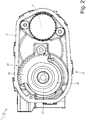
Figure 2 is a front view, with parts removed for clarity, of the throttle valve inFigure 1 ; -
Figure 3 is a front view of a valve body of the throttle valve inFigure 1 ; -
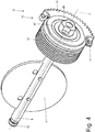
Figure 4 is a perspective view of a movable apparatus of the throttle valve inFigure 1 ; -
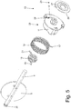
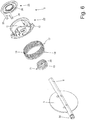
Figures 5 and6 are two different exploded perspective views of the movable apparatus inFigure 4 ; -
Figure 7 is a different perspective view of the movable apparatus inFigure 4 with the return spring also removed; -
Figure 8 is a different perspective view, with parts removed for clarity, of the throttle valve inFigure 1 ; -
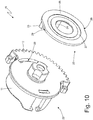
Figures 9 and10 are two different perspective views of two components of an end gear of the movable apparatus inFigure 4 ; and -
Figure 11 is a schematic view of a station for calibrating the limp-home position of the throttle valve inFigure 1 . - In
Figure 1 , an electronically controlled throttle valve for an internal combustion heat engine (not shown) is globally indicated with numeral reference 1. - The throttle valve 1 comprises a
metal valve body 2 in which anintake duct 4 is obtained, through which the air sucked in from the internal combustion heat engine passes. Theintake duct 4 is engaged by athrottle plate 5, which moves between an opening position and a closing position of theintake duct 4 due to the effect of the action of an electric motor 3 (shown schematically inFigure 2 ). In particular, as shown inFigure 4 , thethrottle plate 5 is fitted onto ametal shaft 6, which is mounted rotatably about alongitudinal rotation axis 7 to rotate between the opening position and the closing position under the control of theelectric motor 3, which is coupled to theshaft 6 by means of a gear transmission 8 (only partially shown inFigure 4 ). - As shown in
Figure 1 , the electric motor 3 (not shown) is arranged in atubular housing 9 arranged by the side of theintake duct 4 and it has a shaft, which is mechanically connected to theshaft 6 by means of thegear transmission 8. Thegear transmission 8 comprises a cogwheel (not shown), which is angularly integral with the shaft of theelectric motor 3, anend gear 10, which is angularly integral with theshaft 6, and an intermediate cogwheel (not shown), which is mounted idle on thevalve body 2 and interposed between the cogwheel of theelectric motor 3 and theend gear 10. Preferably, the intermediate cogwheel (not shown) has a first series of teeth coupled to the cogwheel of theelectric motor 3 and a second series of teeth coupled to theend gear 10; the diameter of the first series of teeth is different from the diameter of the second series of teeth, so the intermediate cogwheel (not shown) determines a non-unitary gear ratio. According to what is better illustrated inFigures 10 and11 , theend gear 10 comprises a centralcylindrical body 11, which is fitted onto the shaft 6 (i.e. it is angularly integral with the shaft 6) and is provided with atoothed segment 12 provided with a series of teeth coupled to the intermediate cogwheel (not shown). - The intermediate cogwheel (not shown) and the
end gear 10 are normally made of a plastic material, while the cogwheel (not shown) of theelectric motor 3 is normally made of sintered steel. According to a preferred embodiment, theend gear 10 is made of a plastic material and it is overmoulded around theshaft 6, which is normally made of a metal material (for example, steel or aluminium). - The assembly of the
throttle plate 5, theshaft 6 and theend gear 10 make up a movable apparatus, which, in use, rotates about therotation axis 7 under the control of theelectric motor 3. - According to a preferred embodiment, the
gear transmission 8 is arranged in a chamber of thevalve body 2, which is sealed by a removable cover and made of a plastic material. - According to a preferred embodiment, the throttle valve comprises an inductive position sensor of the "contactless type" (not shown), which is coupled to the
shaft 6 and designed to detect the angular position of theshaft 6 and, thus, of thethrottle plate 5, to enable a feedback control of the position of thethrottle plate 5. For example, the position sensor (not shown) could be of the type described in patentUS6236199B1 and thus comprise a rotor, which is angularly integral with the shaft 6 (in particular with the end gear 10) and a stator supported by the cover and arranged, in use, facing the rotor. Alternatively, the position sensor (not shown) could be of the magnetostrictive type and thus comprise a permanent magnet integral with the shaft 6 (in particular with the end gear 10). - According to a preferred embodiment, a thread-forming minimum screw is comprised, which is screwed into a hole 13 (shown in
Figure 1 ) obtained through thevalve body 2 and cooperating with thetoothed segment 12 of theend gear 10; when theshaft 6 is brought by the action of theelectric motor 3 into the closing position, the rotation of theshaft 6 is not stopped by the impact between thethrottle plate 5 and the walls of theintake duct 4, but it is stopped by the impact of thetoothed segment 12 of theend gear 10 against the minimum screw. Such solution is made necessary due to the fact that a potential impact between thethrottle plate 5 and the walls of theintake duct 4 could determine an interlocking of thethrottle plate 5 with the walls of theintake duct 4 with a consequent jamming of the throttle valve 1. - According to what is illustrated in
Figures 5 and6 , the throttle valve 1 comprises areturn spring 14, which is a spiral torsion spring (i.e. the spring deforms according to a circular displacement, generating a resistive torque) and it tends to rotate theshaft 6 in a closing direction with a movement, which brings thethrottle plate 5 towards the closing position. The throttle valve 1 further comprises a counteringspring 15, which is a spiral torsion spring (i.e. the spring deforms according to a circular displacement, generating a resistive torque) and it tends to rotate theshaft 6 in an opening direction, opposite the closing direction with a movement, which brings thethrottle plate 5 towards an opening position. Thereturn spring 14 generates a lower torque than the torque generated by the counteringspring 15, therefore, in general, the combination of the effects of thesprings shaft 6 in the opening direction and towards an opening position of thethrottle plate 5. - As better described below, a
striking element 16 is comprised (shown inFigures 3 and8 ), which is obtained on the valve body 2 (i.e. it is a part of the valve body 2) and it forms a stop for the rotation movement impressed by the countering spring 15 (i.e. the counteringspring 15 cannot rotate theshaft 6 beyond the limit position established by the striking element 16), defining an intermediate position of partial opening (between a limit position of complete closing and a limit position of complete opening) or limp-home position. In the absence of interventions by theelectric motor 3, the rotation towards the opening position of theshaft 6, due to the effect of the action of thesprings spring 15 overcomes the torque generated by theclosing spring 14 and the rotation of theshaft 6 impressed by the counteringspring 15 stops in the limit position established by the striking element 16 (i.e. in the limp-home position). In this way, in the absence of the action of theelectric motor 3 the shaft 6 (and thus the throttle plate 5) is arranged in the limp-home position. - The stopping of the rotation of the
shaft 6 towards the opening, which occurs during the opening movement from the completely closed position, is due to the fact that thetoothed segment 12 integral with theshaft 6 stops against oneend 21 of the counteringspring 15, which remains still, resting on thestriking element 16, when theshaft 6 moves between the limp-home position and the complete closing position. - When the
electric motor 3 is activated, the engine torque generated by theelectric motor 3 is capable of rotating the shaft 6 (and thus the throttle plate 5) into a position of complete closing against the torque generated by the counteringspring 15 and it is capable of rotating the shaft 6 (and thus the throttle plate 5) into a position of maximum opening against the torque generated by thereturn spring 14. - According to what is illustrated in
Figure 4 , thereturn spring 14 is coaxial to therotation axis 7 and it is arranged about thecylindrical body 11 of the end gear 10 (i.e. it surrounds thecylindrical body 11 of the end gear 10). According to what is illustrated inFigure 7 , the counteringspring 15 is coaxial to therotation axis 7 and it is arranged inside thecylindrical body 11 of the end gear 10 (and thus it is mounted in thecylindrical body 11 of the end gear 10). - According to what is illustrated in
Figures 5 and6 , thereturn spring 14 has oneend 17 resting on a wall of the end gear 10 (in particular, on a side wall of thetoothed segment 12, as shown inFigure 4 ) to push on theend gear 10, and oneend 18 opposite theend 17, which is inserted in a seat 19 (shown inFigure 3 ) obtained in thevalve body 2 to be constrained with the valve body 2 (i.e. to "use force" on thevalve body 2 so as to push theend gear 10, and thus theshaft 6 carrying thethrottle plate 5, towards the closing position). - As stated previously, the countering
spring 15 is mounted on theend gear 10; in particular, oneend 20 of the counteringspring 15 is integral with the end gear 10 (i.e. it is inserted in a seat of the end gear 10) and theend 21 of the counteringspring 15 opposite theend 20 is arranged so that theend gear 10, in the rotating movement thereof, from the position of complete closing to the position of opening, impacts against it, thus stopping in the limp-home position. Theend 21 of the countering spring is fixed on thestriking element 16 during the movement of theshaft 6 between the complete closing and limp-home positions. Whereas, during the movement of theshaft 6 between the limp-home and complete opening positions, theend 21 of the countering spring is dragged by theend gear 10, thus not having relative movement with respect to theend 20 of the counteringspring 15, consequently, not further charging the counteringspring 15. - In the absence of the action of the
electric motor 3 and when thethrottle plate 5 is in a position of complete opening, the torque generated by thereturn spring 14 rotates theshaft 6, and thus theend gear 10, with a movement, which tends to bring thethrottle plate 5 towards the closing position. At a certain point, during the rotating movement of theend gear 10 towards the closing position under the thrust of thereturn spring 14, theend 21 of the counteringspring 15 rests on the striking element 16 (as shown inFigure 8 ); at this point, a further rotating movement of theend gear 10 towards the closing position determines a deformation of the counteringspring 15 and so the counteringspring 15 opposes, with the elastic force thereof, a further rotating movement and the end gear 10 (thus theshaft 6 and the throttle plate 5) stop in the limp-home position established by thestriking element 16. In other words, on reaching the limp-home position, theend 21 of the counteringspring 15 rests on the striking element 16 (as shown inFigure 8 ) and thus a further rotation of theend gear 10 towards the position of complete closing deforms the counteringspring 15, which reacts by generating a resistive torque, which tends to bring theend gear 10 back to the limp-home position, the torque generated by the counteringspring 15 being greater than the torque generated by thereturn spring 14. - During the movement from the limp-home position to the position of complete closing, the
return spring 14 generates a torque, which assists the movement of theshaft 6; thus, while theelectric motor 3 actuates this movement, it is assisted by the action of thereturn spring 14. - Vice versa, during the movement from the position of complete closing to the limp-home position, the
return spring 14 generates a torque, which opposes the movement of theshaft 6; thus, during this movement, theelectric motor 3 must also overcome the action generated by thereturn spring 14. - In fact, the
return spring 14 always generates a torque aimed at closing the throttle plate 5: in the case of a closing movement, thereturn spring 14 generates a favourable torque; in the case of an opening movement, thereturn spring 14 generates an opposite torque. - In summary, in the absence of intervention by the
electric motor 3, the shaft 6 (thus the throttle plate 5) is arranged in the limp-home position: in fact, to move from the limp-home position established by thestriking element 16 it would be necessary to overcome the elastic force generated by the return spring 14 (to go from the limp-home position towards the position of complete opening) or it would be necessary to overcome the elastic force generated by the countering spring 15 (to go from the limp-home position towards the position of complete closing) and, to overcome the elastic force generated by thesprings electric motor 3 is needed. - According to what is illustrated in
Figures 9 and10 , theend gear 10 comprises amain component 22, on which thecylindrical body 11 and thetoothed segment 12 are obtained, and anadditional component 23, which is coupled and heat-welded (using subsequently described methods) to themain component 22. As illustrated inFigure 7 , the only function of theadditional component 23 is to establish the coupling with theend 21 of the countering spring 15: in fact, theadditional component 23 comprises twocoupling elements Figure 9 ) inside which theend 21 of the countering spring is arranged (as illustrated inFigure 7 ). In particular, thecoupling element 25 is arranged at thestriking element 16 and theend 21 of the counteringspring 15 is resting on thecoupling element 25 in the limp-home position. - According to what is illustrated in
Figures 9 and10 , theadditional component 23 has acentral body 26 with the shape of a disc, from which the twocoupling elements central body 26 of theadditional component 23 has anannular groove 27, which, as described better below, identifies the connection area by means of heat-welding between theadditional component 23 and themain component 22; in other words, theadditional component 23 is constrained to themain component 22 by means of an annular heat-welding, which develops at theannular groove 27. - According to a preferred embodiment, the
additional component 23 is made of a first plastic material, which is transparent to laser beams, i.e. with a plastic material, which is crossed by laser beams without absorbing the laser beams (thus without heating due to the effect of the laser beams; whereas, themain component 22 is made of a second plastic material, which is at least partially different from the first plastic material and absorbs laser beams (thus heating due to the effect of the laser beams). According to a preferred embodiment, the first plastic material, which makes up theadditional component 23 has the same base as the second plastic material, which makes up the main component 22 (to allow a good mutual welding thereof) with the addition of additives, making it transparent to laser beams. - According to what is illustrated in
Figure 10 , themain component 22 comprises a throughopening 28 inside which the twocoupling elements additional component 23 are arranged when theadditional component 23 is coupled to themain component 22. The angular extension of the through opening 28 of themain component 22 is greater than the angular extension of thecoupling elements additional component 23 with respect to themain component 22; in other words, after being coupled to each other and before being connected by means of heat-welding, the twocomponents components Figure 7 , the wholemain component 22 is shaped to enable theadditional component 23 to rotate with respect to the main component 22 (clearly before carrying out the heat-welding): in fact, it is clear that there is a free space between the twocoupling elements additional component 23 and thecylindrical body 11 of themain component 22 to enable the twocoupling elements additional component 23 to rotate with respect to thecylindrical body 11 of themain component 22. - According to a preferred embodiment better illustrated in
Figures 9 and10 , thecentral body 26 of theadditional component 23 has two flattenedportions 29, which give thecentral body 26 an asymmetrical shape, which can be firmly engaged (through a shape coupling) by a tool (described below) so as to make the tool angularly integral with thecentral body 26. - According to a preferred embodiment, better illustrated in
Figure 7 , at one end of theshaft 6 opposite the chamber of the valve body 2 (i.e. opposite the end gear 10) there is ascrewdriver input 30 made in one piece with theshaft 6, which can be engaged by a tool to rotate theshaft 6. In particular, thescrewdriver input 30 can be accessed from the outside also when theshaft 6 is mounted in thevalve body 2 due to a special opening obtained in thevalve body 2. - During the assembly of the throttle valve, after assembling the
return spring 14 on thevalve body 2, the counteringspring 15 and theadditional component 23 of theend gear 10 are mounted on theshaft 6 provided with themain component 22 of the end gear 10 (which is overmoulded on the shaft 6); it is important to point out that in this step theadditional component 23 is not (yet) heat-welded to themain component 22 thus leaving theadditional component 23 free to rotate with respect to themain component 22. At this point, the shaft 6 (bearing the twocomponents end gear 10 and the countering spring 15) is inserted in thevalve body 2, where it rests on two special supports, which make up two rolling guides. During the assembly of theshaft 6, it is necessary to apply a rotation to theshaft 6 so that thetoothed segment 12 engages with theend 17 of thereturn spring 14 bringing it into the preloaded position. Once theshaft 6 is in position, thethrottle plate 5 is inserted into the special slit obtained in the metal part of the shaft 6 (which is inside the intake duct 4); at this point, thethrottle plate 5 is constrained to theshaft 6 by means of screws. - On completion of assembly and mounting the internal movable apparatus, it is necessary to proceed with calibrating the limp-home position, which terminates with the "freezing" of the angular position of the two
components end gear 10 by means of heat-welding. - A
station 31 for calibrating the limp-home position of the throttle valve 1 is shown inFigure 11 . - The
calibration station 31 comprises aduct 32, which is pneumatically connected to theintake duct 4 of the throttle valve 1, it is designed to apply a depression (suction) similar to the depression (suction) of a suction duct of an internal combustion heat engine, and it is provided with a flow meter 33 (for example, a mass flow sensor); during calibration of the limp-home position, theduct 32 is designed to circulate an air flow (similar to the flow of air in a suction duct of an internal combustion heat-engine), through theintake duct 4, whose flow rate is measured by the flow meter 33. - The
calibration station 31 comprises an actuator 34, which is designed to rotate theshaft 6 of the throttle valve by acting on thescrewdriver input 30 and it is controlled by the flow meter 33; in particular, the actuator 34 comprises a screwdriver, which engages thescrewdriver input 30 and an electric motor (generally provided with a reducer), which is designed to rotate the screwdriver itself with great precision. - The
calibration station 31 comprises atool 35, which is designed to engage thecentral body 26 of theadditional component 23 of theend gear 10 by means of a shape coupling (in particular, at the two flattened portions 29), both to prevent the rotation of theadditional component 23 and to press (push)theadditional component 23 axially against themain component 22. In other words, thetool 35 has a double function: it must engage thecentral body 26 of theadditional component 23 with a shape coupling (at the two flattened portions 29) to prevent the rotation of theadditional component 23 and, at the same time, it must apply an axial pressure on theadditional component 23 to keep theadditional component 23 pressed forcefully against themain component 22. According to a preferred embodiment, thetool 35 is made of a plastic material, which is transparent to laser beams, i.e. with a plastic material, which is crossed by laser beams without absorbing the laser beams. - Finally, the
calibration station 31 comprises anemitter 36, which is designed to emit alaser beam 37, which is directed towards thecentral body 26 of theadditional component 23 of the end gear 10 (in particular, at theannular groove 27 of the central body 26). Thelaser beam 37 crosses thetool 35 substantially integral (which is transparent to the laser beam 37), thus thelaser beam 37 crosses thecentral body 26 of theadditional component 23 substantially integral (which is transparent to the laser beam 37), and finally thelaser beam 37 reaches themain component 22, which absorbs thelaser beam 37, heating up and causing the localised fusion of the plastic material. The combined effect of the heat generated by thelaser beam 37, which affects themain component 22, and the axial pressure exerted by thetool 35 determines the heat-welding of themain component 22 to thecentral body 26 of theadditional component 23. - The
calibration station 31 described above is completely automated; it is clear that some functions of thecalibration station 31 could be performed manually by an operator instead of by an automatic device. - In use, the throttle valve 1 is coupled to the
duct 32, to the actuator 34 and to thetool 35, while theadditional component 23 of theend gear 10 is left free to rotate with respect to themain component 22 of the end gear 10 (i.e. themain component 22 of theend gear 10 is left free to rotate with respect to theadditional component 23 of the end gear 10). In this situation, thethrottle plate 5 is in the limp-home position (theelectric motor 3 hasn't been mounted yet or, if already mounted, it is kept switched off, and so thethrottle plate 5 is moved solely by the action of thesprings 14 and 15). Air is made to circulate at a pressure similar to the pressure in the suction duct of an internal combustion heat engine, along the duct 32 (and so through the throttle valve 1). Thus, the actuator 34 acts on thescrewdriver input 30 of the shaft 6 (i.e. it rotates theshaft 6 acting on the screwdriver input 30) under the control of the flow meter 33 to vary the air flow rate flowing through the throttle valve 1 in the limp-home position, pursuing (searching for) the nominal (desired) air flow rate. - When the actuator 34 rotates the
shaft 6 acting on the screwdriver input 30), the rotation of theshaft 6 is transmitted to themain component 22 of the end gear 10 (which is rigidly constrained to the shaft 6) but not to theadditional component 23, which is (still) angularly decoupled from theadditional component 23 and held still by thetool 35; consequently, the rotation of theshaft 6 imposed by the actuator 34 determines a corresponding rotation of themain component 22 of theend gear 10 with respect to theadditional component 23, which, in turn, determines a displacement of the position of thecoupling elements 24 and 25 (integral with the additional component 23) with respect to themain component 22 of theend gear 10. - In other words, after assembly, the action of the countering
spring 15 brings into mutual contact theend 21 of the counteringspring 15, theelement 25 of theadditional component 23, and thecylindrical body 11 of the main component 22 (i.e. all three of these bodies are in mutual contact). At this point, theadditional component 23 is locked by thetool 35 and the main component 22 (integral with the throttle plate 5) is rotated by the actuator 34 by the angle needed to reach the nominal (desired) limp-home flow rate. - When the nominal (desired) limp-home flow rate is reached, i.e. when the flow meter 33 detects that the nominal (desired) limp-home flow rate flows through the throttle valve 1 arranged in the limp-home position, it is possible to "freeze" the angular position of the
additional component 23 with respect to themain component 22, performing the laser heat-welding of thecentral body 26 of theadditional component 23 to themain component 22, through the combined action of theemitter 36 and thetool 35, according to the methods described previously. - Then, the throttle valve 1 is removed from the
calibration station 31 and the assembly of the other components of the throttle valve 1 is completed (for example, the intermediate cogwheel, theelectric motor 3 if it wasn't already assembled beforehand, and the cover); it is important to note that the components, which are mounted afterwards in the throttle valve 1 (for example, the intermediate cogwheel) could hinder the coupling of thetool 35 to thecentral body 26 of theadditional component 23 and thus couldn't be mounted before calibrating the limp-home position. - In the embodiment shown in the appended Figures, the throttle valve 1 described above is designed to be inserted along a suction duct of an internal combustion heat engine, to regulate the flow rate of air sucked in. According to an alternative embodiment, the throttle valve 1 described above is designed to be inserted along a discharge duct of an internal combustion heat engine to regulate the flow rate of discharge gas. According to a further embodiment, the throttle valve 1 described above is designed to be inserted along a duct of a hydrogen propulsion system using fuel cells, for example, to regulate the flow rate of the air/hydrogen mixture. Generally, the throttle valve 1 described above can be used along any duct of a vehicle propulsion system to regulate the fluid flow rate flowing along the duct (clearly when it is necessary that, in the absence of external interventions, the throttle valve 1 is arranged spontaneously in an intermediate position of partial opening corresponding, in the case of suction, to the limp-home position).
- The throttle valve 1 described above offers several advantages.
- Firstly, in the throttle valve 1 described above, the air flow rate which flows in the limp-home position can be established in a highly precise manner regardless of the structural tolerances since the errors introduced by the structural tolerances are compensated during the step of final calibration, varying the position of the additional component 23 (which bears the two
coupling elements end 21 of the countering spring 15) with respect to themain component 22. In general, the tolerance on the air flow rate flowing in the limp-home position can be less than ±4-5%. - Furthermore, the throttle valve 1 described above is simple and cheap to make because, with respect to a similar known throttle valve it comprises, as the only addition, the
additional component 23, which is, in the throttle valve 1 as a whole, a "small piece of moulded plastic". - Finally, the calibration of the limp-home flow rate in the throttle valve 1 described above is particularly simple and, above all, can be automated and can thus be carried out in a quick and certifiable manner.
-
- 1
- throttle valve
- 2
- valve body
- 3
- electric motor
- 4
- intake duct
- 5
- throttle plate
- 6
- shaft
- 7
- rotation axis
- 8
- gear transmission
- 9
- tubular housing
- 10
- end gear
- 11
- cylindrical body
- 12
- toothed segment
- 13
- hole
- 14
- return spring
- 15
- countering spring
- 16
- striking element
- 17
- end
- 18
- end
- 19
- seat
- 20
- end
- 21
- end
- 22
- main component
- 23
- additional component
- 24
- coupling element
- 25
- coupling element
- 26
- central body
- 27
- annular groove
- 28
- through opening
- 29
- flattened portions
- 30
- screwdriver input
- 31
- calibration station
- 32
- duct
- 33
- flow rate meter
- 34
- actuator
- 35
- tool
- 36
- emitter
- 37
- laser beam
Claims (16)
- A throttle valve (1) comprising:a valve body (2);an intake duct (4), which is obtained in the valve body (2);a throttle plate (5), which is arranged in the intake duct (4);a shaft (6), which is mounted so as to rotate in the valve body (2) and supports the throttle plate (5);an electric motor (3);a gear transmission (8), which couples the electric motor (3) to the shaft (6) and comprises an end gear (10), which is integral with the shaft (6);a return spring (14), which is designed to rotate the throttle plate (5) towards a closing position;a striking element (16), which is obtained in the valve body (2) and establishes an intermediate position of partial opening; anda countering spring (15), which is fitted on the end gear (10), is designed to rotate the throttle plate (5) towards an opening position and up to the intermediate position, and has a first end (21), which is designed to rest against the striking element (16) during the rotation of the end gear (10);wherein the end gear (10) comprises at least one coupling element (24, 25), which is designed to rest against the first end (21) of the countering spring (15);the throttle valve (1) is characterised in that:the end gear (10) comprises a main component (22), which supports the countering spring (15) and an additional component (23), which is coupled to the main component (22) and supports the coupling element (24, 25);the additional component (23) is heat-welded to the main component (22) so as to prevent the rotation between the two components (22, 23); andthe main component (22) is shaped so as to enable a rotation between the two components (22, 23) before the two components (22, 23) are heat-welded.
- The throttle valve (1) according to claim 1, wherein the additional component (23) comprises two coupling elements (24, 25), which make up the two tines of a fork, inside which the first end (21) of the countering spring (15) is arranged.
- The throttle valve (1) according to claim 1 or 2, wherein the additional component (23) has a disc-shaped central body (26), from which the coupling element (24, 25) projects.
- The throttle valve (1) according to claim 1, 2 or 3, wherein the additional component (23) has an annular groove (27) at which the heat-welded joint between the additional component (23) and the main component (22) is arranged.
- The throttle valve (1) according to one of the claims from 1 to 4, wherein:the additional component (23) is made of a first plastic material, which is transparent to laser beams; andthe main component (22) is made of a second plastic material, which is at least partially different from the first plastic material and absorbs laser beams.
- The throttle valve (1) according to claim 5, wherein the first plastic material making up the additional component (23) has the same base as the second plastic material making up the main component (22) with the addition of additives, making it transparent to laser beams.
- The throttle valve (1) according to one of the claims from 1 to 6, wherein the main component (22) comprises a through opening (28) inside which the coupling element (24, 25) of the additional component (23) is arranged.
- The throttle valve (1) according to one of the claims from 1 to 7, wherein the through opening (28) of the main component (22) has a greater angular extension than an angular extension of the coupling element (24, 25) of the additional component (23) so as to enable a relative rotation of the additional component (23) with respect to the main component (22).
- The throttle valve according to one of the claims from 1 to 8, wherein a central body (26) of the additional component (23) has two flattened portions (29), which give the central body (26) an asymmetrical shape, which can be firmly engaged by a tool (35) so as to make the tool (35) angularly integral with the central body (26).
- The throttle valve (1) according to one of the claims from 1 to 9, wherein at one end of the shaft (6) opposite the end gear (10) there is a screwdriver input (30), which can be engaged by a tool to rotate the shaft (6) .
- The throttle valve (1) according to one of the claims from 1 to 10, wherein the main component (22) of the end gear (10) is overmoulded around the shaft (6).
- The throttle valve (1) according to one of the claims from 1 to 11, wherein a second end (20) of the countering spring (15) opposite the first end (21) is integral with the end gear (10).
- A method to adjust the intermediate position of a throttle valve (1) according to one of the claims from 1 to 12; the adjustment method comprises the steps of:mounting, in the valve body (2) the throttle plate (5), the shaft (6), the springs (14, 15), and the end gear (10) with the main component (22) free to rotate with respect to the additional component (23);preventing the rotation of the additional component (23) by means of an outer constraint;adjusting the angular position of the shaft (6), and then, of the throttle plate (5) and of the main component (22) of the end gear (10), so as to obtain the desired fluid flow rate in the intermediate position; andafter having obtained the desired fluid flow rate in the intermediate position, creating a heat-welded joint between the additional component (23) and the main component (22) so as to rigidly constrain the additional component (23) to the main component (22).
- The adjustment method according to claim 13, wherein the heat-welded joint between the additional component (23) and the main component (22) is created by directing a laser beam (37) against the additional component (23).
- The adjustment method according to claim 14, wherein the heat-welded joint between the additional component (23) and the main component (22) is created by axially pushing the additional component (23) against the main component (22) by means of a tool (35), which is also used to prevent the rotation of the additional component (23) .
- The adjustment method according to claim 15, wherein the tool (35) is made of a plastic material, which is transparent to laser beams.
Applications Claiming Priority (1)
| Application Number | Priority Date | Filing Date | Title |
|---|---|---|---|
| IT102018000003347A IT201800003347A1 (en) | 2018-03-07 | 2018-03-07 | BUTTERFLY VALVE FOR AN INTERNAL COMBUSTION ENGINE WITH THE POSSIBILITY OF ADJUSTING THE LIMP-HOME POSITION AND RELATED METHOD OF ADJUSTING THE LIMP-HOME POSITION |
Publications (2)
| Publication Number | Publication Date |
|---|---|
| EP3536935A1 true EP3536935A1 (en) | 2019-09-11 |
| EP3536935B1 EP3536935B1 (en) | 2021-04-28 |
Family
ID=62386793
Family Applications (1)
| Application Number | Title | Priority Date | Filing Date |
|---|---|---|---|
| EP19161422.1A Active EP3536935B1 (en) | 2018-03-07 | 2019-03-07 | A throttle valve with the possibility of adjusting an intermediate position of partial opening and relative method to adjust the intermediate position |
Country Status (4)
| Country | Link |
|---|---|
| US (1) | US11041449B2 (en) |
| EP (1) | EP3536935B1 (en) |
| JP (1) | JP7237657B2 (en) |
| IT (1) | IT201800003347A1 (en) |
Cited By (2)
| Publication number | Priority date | Publication date | Assignee | Title |
|---|---|---|---|---|
| CN116379172A (en) * | 2023-03-24 | 2023-07-04 | 宁波方太厨具有限公司 | Bypass valve and water heater containing it |
| IT202300020280A1 (en) | 2023-10-02 | 2025-04-02 | Stellantis Europe Spa | INTERNAL COMBUSTION ENGINE WITH OPTIMIZED INSTALLATION OF A THROTTLE VALVE |
Families Citing this family (10)
| Publication number | Priority date | Publication date | Assignee | Title |
|---|---|---|---|---|
| US10920890B2 (en) * | 2019-03-07 | 2021-02-16 | Denso International America, Inc. | Air flow leakage control via new valve gear design and assembly process |
| US11655788B2 (en) * | 2019-05-03 | 2023-05-23 | Walbro Llc | Charge forming device with throttle valve |
| EP3800716B1 (en) * | 2019-10-03 | 2022-05-04 | Marelli Europe S.p.A. | Throttle valve for adjusting the feeding of a gas to a fuel cell and electric drive vehicle including the throttle valve |
| EP3904725A1 (en) * | 2020-05-01 | 2021-11-03 | Illinois Tool Works, Inc. | Gear train for a valve actuator |
| CN112833198A (en) * | 2021-01-22 | 2021-05-25 | 宁波经济技术开发区恒阳机械有限公司 | An automotive electronic exhaust active valve structure |
| CN113738894B (en) * | 2021-09-17 | 2022-07-15 | 浙江德卡控制阀仪表有限公司 | A butterfly valve with high precision adjustment function |
| WO2023072636A1 (en) * | 2021-10-26 | 2023-05-04 | Vitesco Technologies GmbH | Throttle-valve actuator unit, fuel cell system comprising a throttle-valve actuator unit of this kind, and motor vehicle comprising a fuel cell system of this kind |
| CN114483326B (en) * | 2022-01-27 | 2023-04-07 | 温州市温纳汽车配件有限公司 | Electronic throttle valve |
| JP7428925B2 (en) * | 2022-06-10 | 2024-02-07 | 株式会社デンソーダイシン | Throttle valve device and method for manufacturing the throttle valve device |
| CN117514479A (en) * | 2022-08-05 | 2024-02-06 | 爱三工业株式会社 | air-saving device |
Citations (7)
| Publication number | Priority date | Publication date | Assignee | Title |
|---|---|---|---|---|
| EP1099839A2 (en) | 1999-11-11 | 2001-05-16 | Visteon Global Technologies, Inc. | Electronic throttle return mechanism with default and gear backlash control |
| US6236199B1 (en) | 1997-09-05 | 2001-05-22 | Hella Kg Hueck & Co. | Inductive angle sensor |
| DE10202096A1 (en) | 2002-01-21 | 2003-07-24 | Siemens Ag | Throttle valve support and drive system for internal combustion engine has stirrup connected to accelerator pedal and moving between minimum and maximum opening stops |
| EP1515023A1 (en) * | 2003-09-15 | 2005-03-16 | Magneti Marelli Powertrain S.p.A. | An electronically controlled butterfly valve provided with a flat leaf spring and a spiral spring to establish the limp-home position |
| US20060231072A1 (en) | 2005-04-14 | 2006-10-19 | Hitachi, Ltd. | Motor-driven throttle valve control device for internal combustion engine |
| US20130284147A1 (en) * | 2012-04-26 | 2013-10-31 | Delphi Technologies, Inc. | Throttle return spring with eccentric locator coils |
| WO2016170292A1 (en) * | 2015-04-23 | 2016-10-27 | Valeo Systemes De Controle Moteur | Air pipe valve of an engine of a motor vehicle |
Family Cites Families (15)
| Publication number | Priority date | Publication date | Assignee | Title |
|---|---|---|---|---|
| US3535948A (en) * | 1968-11-29 | 1970-10-27 | John Harold Winzeler | Worm gearing |
| US5271287A (en) * | 1992-07-28 | 1993-12-21 | Materials Analysis, Inc. | Multi-metal composite gear/shaft |
| JP3213863B2 (en) * | 1993-06-21 | 2001-10-02 | 本田技研工業株式会社 | Throttle valve device |
| US6364287B1 (en) * | 2000-08-07 | 2002-04-02 | Visteon Global Technologies, Inc. | Electronic throttle return spring assembly |
| DE10102776A1 (en) * | 2001-01-23 | 2002-07-25 | Bosch Gmbh Robert | Manual return device for the choke flap of a combustion engine, has spring and cam mechanism with reduced play so that the choke flap can be accurately positioned should its electric drive fail |
| US6589380B2 (en) * | 2001-02-07 | 2003-07-08 | Delphi Technologies, Inc. | Laser welded air control valve and method |
| JP2002256977A (en) * | 2001-03-06 | 2002-09-11 | Walbro Japan Inc | Carburetor for small two stroke internal combustion engine |
| JP2003083095A (en) * | 2001-07-05 | 2003-03-19 | Denso Corp | Engine throttle device |
| JP3751946B2 (en) * | 2003-02-03 | 2006-03-08 | 株式会社日立製作所 | Engine throttle device |
| US7051707B2 (en) * | 2003-03-07 | 2006-05-30 | Denso Corporation | Electronically controlled throttle control apparatus |
| DE102005031341A1 (en) * | 2005-07-05 | 2007-01-11 | Robert Bosch Gmbh | Actuator for an actuator |
| JP4220504B2 (en) * | 2005-07-25 | 2009-02-04 | 三菱電機株式会社 | Intake control system |
| JP2009299673A (en) * | 2008-05-13 | 2009-12-24 | Aisan Ind Co Ltd | Throttle device of internal combustion engine |
| US20120001105A1 (en) * | 2010-06-30 | 2012-01-05 | Denso Corporation | Valve control apparatus and electric driving apparatus |
| US9546606B2 (en) * | 2014-05-21 | 2017-01-17 | Continental Automotive Systems, Inc. | Electronic throttle body assembly |
-
2018
- 2018-03-07 IT IT102018000003347A patent/IT201800003347A1/en unknown
-
2019
- 2019-03-07 US US16/295,289 patent/US11041449B2/en active Active
- 2019-03-07 JP JP2019041607A patent/JP7237657B2/en active Active
- 2019-03-07 EP EP19161422.1A patent/EP3536935B1/en active Active
Patent Citations (7)
| Publication number | Priority date | Publication date | Assignee | Title |
|---|---|---|---|---|
| US6236199B1 (en) | 1997-09-05 | 2001-05-22 | Hella Kg Hueck & Co. | Inductive angle sensor |
| EP1099839A2 (en) | 1999-11-11 | 2001-05-16 | Visteon Global Technologies, Inc. | Electronic throttle return mechanism with default and gear backlash control |
| DE10202096A1 (en) | 2002-01-21 | 2003-07-24 | Siemens Ag | Throttle valve support and drive system for internal combustion engine has stirrup connected to accelerator pedal and moving between minimum and maximum opening stops |
| EP1515023A1 (en) * | 2003-09-15 | 2005-03-16 | Magneti Marelli Powertrain S.p.A. | An electronically controlled butterfly valve provided with a flat leaf spring and a spiral spring to establish the limp-home position |
| US20060231072A1 (en) | 2005-04-14 | 2006-10-19 | Hitachi, Ltd. | Motor-driven throttle valve control device for internal combustion engine |
| US20130284147A1 (en) * | 2012-04-26 | 2013-10-31 | Delphi Technologies, Inc. | Throttle return spring with eccentric locator coils |
| WO2016170292A1 (en) * | 2015-04-23 | 2016-10-27 | Valeo Systemes De Controle Moteur | Air pipe valve of an engine of a motor vehicle |
Cited By (2)
| Publication number | Priority date | Publication date | Assignee | Title |
|---|---|---|---|---|
| CN116379172A (en) * | 2023-03-24 | 2023-07-04 | 宁波方太厨具有限公司 | Bypass valve and water heater containing it |
| IT202300020280A1 (en) | 2023-10-02 | 2025-04-02 | Stellantis Europe Spa | INTERNAL COMBUSTION ENGINE WITH OPTIMIZED INSTALLATION OF A THROTTLE VALVE |
Also Published As
| Publication number | Publication date |
|---|---|
| US11041449B2 (en) | 2021-06-22 |
| US20190277202A1 (en) | 2019-09-12 |
| EP3536935B1 (en) | 2021-04-28 |
| IT201800003347A1 (en) | 2019-09-07 |
| JP2019173747A (en) | 2019-10-10 |
| JP7237657B2 (en) | 2023-03-13 |
Similar Documents
| Publication | Publication Date | Title |
|---|---|---|
| EP3536935B1 (en) | A throttle valve with the possibility of adjusting an intermediate position of partial opening and relative method to adjust the intermediate position | |
| US7028979B2 (en) | Servo assisted butterfly valve provided with a flat leaf spring and a spiral spring to establish the limp-home position | |
| US9500162B2 (en) | Valve apparatus | |
| JP6675959B2 (en) | Throttle device and method of manufacturing the same | |
| JP5561496B2 (en) | Flow control valve and its assembly method | |
| US7337765B2 (en) | Throttle regulator for vibration compaction machine | |
| CN104145097B (en) | Exhaust turbocharger for use with internal combustion engines | |
| WO2019130647A1 (en) | Valve device | |
| US5052656A (en) | Flow control valve unit | |
| EP1515023B1 (en) | An electronically controlled butterfly valve provided with a flat leaf spring and a spiral spring to establish the limp-home position | |
| JPH06500749A (en) | Hydraulic power steering device | |
| EP4234908A2 (en) | Throttle device | |
| US7441542B2 (en) | Butterfly valves and intake air control devices for internal combustion engines | |
| WO2020170720A1 (en) | Flow control valve and assembly method for same | |
| KR102273742B1 (en) | Assembly method for assembling an exhaust line valve, and corresponding valve | |
| JP2000344119A (en) | Pressure shutoff device for power steering device at stationary steering end position | |
| US7520209B2 (en) | Servo for a gear change | |
| JP2005147012A (en) | Throttle control device and its manufacturing method | |
| JP2009293581A (en) | Throttle valve device | |
| JP6673747B2 (en) | Double eccentric valve and method of manufacturing the same | |
| CN117043454A (en) | Vent | |
| JP2025099135A (en) | Method for manufacturing throttle device, and angular adjustment jig | |
| CN115126605B (en) | Method for manufacturing gas saving device | |
| JP3142615B2 (en) | Joining method between the operating shaft of the flow control valve and the valve member | |
| US7222603B2 (en) | Subunit for an additional control valve device used for an intake pipe of a reciprocating internal combustion engine |
Legal Events
| Date | Code | Title | Description |
|---|---|---|---|
| PUAI | Public reference made under article 153(3) epc to a published international application that has entered the european phase |
Free format text: ORIGINAL CODE: 0009012 |
|
| STAA | Information on the status of an ep patent application or granted ep patent |
Free format text: STATUS: THE APPLICATION HAS BEEN PUBLISHED |
|
| AK | Designated contracting states |
Kind code of ref document: A1 Designated state(s): AL AT BE BG CH CY CZ DE DK EE ES FI FR GB GR HR HU IE IS IT LI LT LU LV MC MK MT NL NO PL PT RO RS SE SI SK SM TR |
|
| AX | Request for extension of the european patent |
Extension state: BA ME |
|
| STAA | Information on the status of an ep patent application or granted ep patent |
Free format text: STATUS: REQUEST FOR EXAMINATION WAS MADE |
|
| 17P | Request for examination filed |
Effective date: 20191219 |
|
| RIC1 | Information provided on ipc code assigned before grant |
Ipc: F16K 1/22 20060101ALI20200918BHEP Ipc: F02D 9/02 20060101ALN20200918BHEP Ipc: F02D 9/10 20060101AFI20200918BHEP |
|
| GRAP | Despatch of communication of intention to grant a patent |
Free format text: ORIGINAL CODE: EPIDOSNIGR1 |
|
| STAA | Information on the status of an ep patent application or granted ep patent |
Free format text: STATUS: GRANT OF PATENT IS INTENDED |
|
| INTG | Intention to grant announced |
Effective date: 20201104 |
|
| GRAS | Grant fee paid |
Free format text: ORIGINAL CODE: EPIDOSNIGR3 |
|
| GRAA | (expected) grant |
Free format text: ORIGINAL CODE: 0009210 |
|
| STAA | Information on the status of an ep patent application or granted ep patent |
Free format text: STATUS: THE PATENT HAS BEEN GRANTED |
|
| RIN1 | Information on inventor provided before grant (corrected) |
Inventor name: MUSOLESI, STEFANO Inventor name: GUIDUZZI, LORENZO Inventor name: CAROTI, FEDERICO |
|
| AK | Designated contracting states |
Kind code of ref document: B1 Designated state(s): AL AT BE BG CH CY CZ DE DK EE ES FI FR GB GR HR HU IE IS IT LI LT LU LV MC MK MT NL NO PL PT RO RS SE SI SK SM TR |
|
| REG | Reference to a national code |
Ref country code: GB Ref legal event code: FG4D |
|
| REG | Reference to a national code |
Ref country code: CH Ref legal event code: EP |
|
| REG | Reference to a national code |
Ref country code: AT Ref legal event code: REF Ref document number: 1387313 Country of ref document: AT Kind code of ref document: T Effective date: 20210515 |
|
| REG | Reference to a national code |
Ref country code: DE Ref legal event code: R096 Ref document number: 602019004129 Country of ref document: DE |
|
| REG | Reference to a national code |
Ref country code: IE Ref legal event code: FG4D |
|
| REG | Reference to a national code |
Ref country code: LT Ref legal event code: MG9D |
|
| REG | Reference to a national code |
Ref country code: AT Ref legal event code: MK05 Ref document number: 1387313 Country of ref document: AT Kind code of ref document: T Effective date: 20210428 |
|
| PG25 | Lapsed in a contracting state [announced via postgrant information from national office to epo] |
Ref country code: BG Free format text: LAPSE BECAUSE OF FAILURE TO SUBMIT A TRANSLATION OF THE DESCRIPTION OR TO PAY THE FEE WITHIN THE PRESCRIBED TIME-LIMIT Effective date: 20210728 Ref country code: AT Free format text: LAPSE BECAUSE OF FAILURE TO SUBMIT A TRANSLATION OF THE DESCRIPTION OR TO PAY THE FEE WITHIN THE PRESCRIBED TIME-LIMIT Effective date: 20210428 Ref country code: NL Free format text: LAPSE BECAUSE OF FAILURE TO SUBMIT A TRANSLATION OF THE DESCRIPTION OR TO PAY THE FEE WITHIN THE PRESCRIBED TIME-LIMIT Effective date: 20210428 Ref country code: LT Free format text: LAPSE BECAUSE OF FAILURE TO SUBMIT A TRANSLATION OF THE DESCRIPTION OR TO PAY THE FEE WITHIN THE PRESCRIBED TIME-LIMIT Effective date: 20210428 Ref country code: HR Free format text: LAPSE BECAUSE OF FAILURE TO SUBMIT A TRANSLATION OF THE DESCRIPTION OR TO PAY THE FEE WITHIN THE PRESCRIBED TIME-LIMIT Effective date: 20210428 Ref country code: FI Free format text: LAPSE BECAUSE OF FAILURE TO SUBMIT A TRANSLATION OF THE DESCRIPTION OR TO PAY THE FEE WITHIN THE PRESCRIBED TIME-LIMIT Effective date: 20210428 |
|
| PG25 | Lapsed in a contracting state [announced via postgrant information from national office to epo] |
Ref country code: IS Free format text: LAPSE BECAUSE OF FAILURE TO SUBMIT A TRANSLATION OF THE DESCRIPTION OR TO PAY THE FEE WITHIN THE PRESCRIBED TIME-LIMIT Effective date: 20210828 Ref country code: GR Free format text: LAPSE BECAUSE OF FAILURE TO SUBMIT A TRANSLATION OF THE DESCRIPTION OR TO PAY THE FEE WITHIN THE PRESCRIBED TIME-LIMIT Effective date: 20210729 Ref country code: PT Free format text: LAPSE BECAUSE OF FAILURE TO SUBMIT A TRANSLATION OF THE DESCRIPTION OR TO PAY THE FEE WITHIN THE PRESCRIBED TIME-LIMIT Effective date: 20210830 Ref country code: SE Free format text: LAPSE BECAUSE OF FAILURE TO SUBMIT A TRANSLATION OF THE DESCRIPTION OR TO PAY THE FEE WITHIN THE PRESCRIBED TIME-LIMIT Effective date: 20210428 Ref country code: RS Free format text: LAPSE BECAUSE OF FAILURE TO SUBMIT A TRANSLATION OF THE DESCRIPTION OR TO PAY THE FEE WITHIN THE PRESCRIBED TIME-LIMIT Effective date: 20210428 Ref country code: PL Free format text: LAPSE BECAUSE OF FAILURE TO SUBMIT A TRANSLATION OF THE DESCRIPTION OR TO PAY THE FEE WITHIN THE PRESCRIBED TIME-LIMIT Effective date: 20210428 Ref country code: NO Free format text: LAPSE BECAUSE OF FAILURE TO SUBMIT A TRANSLATION OF THE DESCRIPTION OR TO PAY THE FEE WITHIN THE PRESCRIBED TIME-LIMIT Effective date: 20210728 Ref country code: LV Free format text: LAPSE BECAUSE OF FAILURE TO SUBMIT A TRANSLATION OF THE DESCRIPTION OR TO PAY THE FEE WITHIN THE PRESCRIBED TIME-LIMIT Effective date: 20210428 |
|
| REG | Reference to a national code |
Ref country code: NL Ref legal event code: MP Effective date: 20210428 |
|
| PG25 | Lapsed in a contracting state [announced via postgrant information from national office to epo] |
Ref country code: SM Free format text: LAPSE BECAUSE OF FAILURE TO SUBMIT A TRANSLATION OF THE DESCRIPTION OR TO PAY THE FEE WITHIN THE PRESCRIBED TIME-LIMIT Effective date: 20210428 Ref country code: RO Free format text: LAPSE BECAUSE OF FAILURE TO SUBMIT A TRANSLATION OF THE DESCRIPTION OR TO PAY THE FEE WITHIN THE PRESCRIBED TIME-LIMIT Effective date: 20210428 Ref country code: CZ Free format text: LAPSE BECAUSE OF FAILURE TO SUBMIT A TRANSLATION OF THE DESCRIPTION OR TO PAY THE FEE WITHIN THE PRESCRIBED TIME-LIMIT Effective date: 20210428 Ref country code: DK Free format text: LAPSE BECAUSE OF FAILURE TO SUBMIT A TRANSLATION OF THE DESCRIPTION OR TO PAY THE FEE WITHIN THE PRESCRIBED TIME-LIMIT Effective date: 20210428 Ref country code: SK Free format text: LAPSE BECAUSE OF FAILURE TO SUBMIT A TRANSLATION OF THE DESCRIPTION OR TO PAY THE FEE WITHIN THE PRESCRIBED TIME-LIMIT Effective date: 20210428 Ref country code: ES Free format text: LAPSE BECAUSE OF FAILURE TO SUBMIT A TRANSLATION OF THE DESCRIPTION OR TO PAY THE FEE WITHIN THE PRESCRIBED TIME-LIMIT Effective date: 20210428 Ref country code: EE Free format text: LAPSE BECAUSE OF FAILURE TO SUBMIT A TRANSLATION OF THE DESCRIPTION OR TO PAY THE FEE WITHIN THE PRESCRIBED TIME-LIMIT Effective date: 20210428 |
|
| REG | Reference to a national code |
Ref country code: DE Ref legal event code: R097 Ref document number: 602019004129 Country of ref document: DE |
|
| PLBE | No opposition filed within time limit |
Free format text: ORIGINAL CODE: 0009261 |
|
| STAA | Information on the status of an ep patent application or granted ep patent |
Free format text: STATUS: NO OPPOSITION FILED WITHIN TIME LIMIT |
|
| 26N | No opposition filed |
Effective date: 20220131 |
|
| PG25 | Lapsed in a contracting state [announced via postgrant information from national office to epo] |
Ref country code: IS Free format text: LAPSE BECAUSE OF FAILURE TO SUBMIT A TRANSLATION OF THE DESCRIPTION OR TO PAY THE FEE WITHIN THE PRESCRIBED TIME-LIMIT Effective date: 20210828 Ref country code: AL Free format text: LAPSE BECAUSE OF FAILURE TO SUBMIT A TRANSLATION OF THE DESCRIPTION OR TO PAY THE FEE WITHIN THE PRESCRIBED TIME-LIMIT Effective date: 20210428 |
|
| PG25 | Lapsed in a contracting state [announced via postgrant information from national office to epo] |
Ref country code: MC Free format text: LAPSE BECAUSE OF FAILURE TO SUBMIT A TRANSLATION OF THE DESCRIPTION OR TO PAY THE FEE WITHIN THE PRESCRIBED TIME-LIMIT Effective date: 20210428 |
|
| REG | Reference to a national code |
Ref country code: CH Ref legal event code: PL |
|
| REG | Reference to a national code |
Ref country code: BE Ref legal event code: MM Effective date: 20220331 |
|
| PG25 | Lapsed in a contracting state [announced via postgrant information from national office to epo] |
Ref country code: LU Free format text: LAPSE BECAUSE OF NON-PAYMENT OF DUE FEES Effective date: 20220307 Ref country code: LI Free format text: LAPSE BECAUSE OF NON-PAYMENT OF DUE FEES Effective date: 20220331 Ref country code: IE Free format text: LAPSE BECAUSE OF NON-PAYMENT OF DUE FEES Effective date: 20220307 Ref country code: CH Free format text: LAPSE BECAUSE OF NON-PAYMENT OF DUE FEES Effective date: 20220331 |
|
| PG25 | Lapsed in a contracting state [announced via postgrant information from national office to epo] |
Ref country code: BE Free format text: LAPSE BECAUSE OF NON-PAYMENT OF DUE FEES Effective date: 20220331 |
|
| GBPC | Gb: european patent ceased through non-payment of renewal fee |
Effective date: 20230307 |
|
| PG25 | Lapsed in a contracting state [announced via postgrant information from national office to epo] |
Ref country code: GB Free format text: LAPSE BECAUSE OF NON-PAYMENT OF DUE FEES Effective date: 20230307 |
|
| PG25 | Lapsed in a contracting state [announced via postgrant information from national office to epo] |
Ref country code: GB Free format text: LAPSE BECAUSE OF NON-PAYMENT OF DUE FEES Effective date: 20230307 |
|
| PG25 | Lapsed in a contracting state [announced via postgrant information from national office to epo] |
Ref country code: MK Free format text: LAPSE BECAUSE OF FAILURE TO SUBMIT A TRANSLATION OF THE DESCRIPTION OR TO PAY THE FEE WITHIN THE PRESCRIBED TIME-LIMIT Effective date: 20210428 Ref country code: CY Free format text: LAPSE BECAUSE OF FAILURE TO SUBMIT A TRANSLATION OF THE DESCRIPTION OR TO PAY THE FEE WITHIN THE PRESCRIBED TIME-LIMIT Effective date: 20210428 |
|
| PG25 | Lapsed in a contracting state [announced via postgrant information from national office to epo] |
Ref country code: HU Free format text: LAPSE BECAUSE OF FAILURE TO SUBMIT A TRANSLATION OF THE DESCRIPTION OR TO PAY THE FEE WITHIN THE PRESCRIBED TIME-LIMIT; INVALID AB INITIO Effective date: 20190307 |
|
| PG25 | Lapsed in a contracting state [announced via postgrant information from national office to epo] |
Ref country code: TR Free format text: LAPSE BECAUSE OF FAILURE TO SUBMIT A TRANSLATION OF THE DESCRIPTION OR TO PAY THE FEE WITHIN THE PRESCRIBED TIME-LIMIT Effective date: 20210428 |
|
| PG25 | Lapsed in a contracting state [announced via postgrant information from national office to epo] |
Ref country code: MT Free format text: LAPSE BECAUSE OF FAILURE TO SUBMIT A TRANSLATION OF THE DESCRIPTION OR TO PAY THE FEE WITHIN THE PRESCRIBED TIME-LIMIT Effective date: 20210428 |
|
| PGFP | Annual fee paid to national office [announced via postgrant information from national office to epo] |
Ref country code: DE Payment date: 20260219 Year of fee payment: 8 |
|
| PGFP | Annual fee paid to national office [announced via postgrant information from national office to epo] |
Ref country code: IT Payment date: 20260219 Year of fee payment: 8 |
|
| PGFP | Annual fee paid to national office [announced via postgrant information from national office to epo] |
Ref country code: FR Payment date: 20260219 Year of fee payment: 8 |