EP3536925A1 - Sub-chamber gas engine - Google Patents
Sub-chamber gas engine Download PDFInfo
- Publication number
- EP3536925A1 EP3536925A1 EP17880033.0A EP17880033A EP3536925A1 EP 3536925 A1 EP3536925 A1 EP 3536925A1 EP 17880033 A EP17880033 A EP 17880033A EP 3536925 A1 EP3536925 A1 EP 3536925A1
- Authority
- EP
- European Patent Office
- Prior art keywords
- chamber
- precombustion
- main
- curvature
- hole portion
- Prior art date
- Legal status (The legal status is an assumption and is not a legal conclusion. Google has not performed a legal analysis and makes no representation as to the accuracy of the status listed.)
- Withdrawn
Links
Images





Classifications
-
- F—MECHANICAL ENGINEERING; LIGHTING; HEATING; WEAPONS; BLASTING
- F02—COMBUSTION ENGINES; HOT-GAS OR COMBUSTION-PRODUCT ENGINE PLANTS
- F02B—INTERNAL-COMBUSTION PISTON ENGINES; COMBUSTION ENGINES IN GENERAL
- F02B19/00—Engines characterised by precombustion chambers
- F02B19/10—Engines characterised by precombustion chambers with fuel introduced partly into pre-combustion chamber, and partly into cylinder
-
- F—MECHANICAL ENGINEERING; LIGHTING; HEATING; WEAPONS; BLASTING
- F02—COMBUSTION ENGINES; HOT-GAS OR COMBUSTION-PRODUCT ENGINE PLANTS
- F02B—INTERNAL-COMBUSTION PISTON ENGINES; COMBUSTION ENGINES IN GENERAL
- F02B19/00—Engines characterised by precombustion chambers
- F02B19/16—Chamber shapes or constructions not specific to sub-groups F02B19/02 - F02B19/10
- F02B19/18—Transfer passages between chamber and cylinder
-
- F—MECHANICAL ENGINEERING; LIGHTING; HEATING; WEAPONS; BLASTING
- F02—COMBUSTION ENGINES; HOT-GAS OR COMBUSTION-PRODUCT ENGINE PLANTS
- F02B—INTERNAL-COMBUSTION PISTON ENGINES; COMBUSTION ENGINES IN GENERAL
- F02B19/00—Engines characterised by precombustion chambers
- F02B19/10—Engines characterised by precombustion chambers with fuel introduced partly into pre-combustion chamber, and partly into cylinder
- F02B19/1004—Engines characterised by precombustion chambers with fuel introduced partly into pre-combustion chamber, and partly into cylinder details of combustion chamber, e.g. mounting arrangements
- F02B19/1014—Engines characterised by precombustion chambers with fuel introduced partly into pre-combustion chamber, and partly into cylinder details of combustion chamber, e.g. mounting arrangements design parameters, e.g. volume, torch passage cross sectional area, length, orientation, or the like
-
- F—MECHANICAL ENGINEERING; LIGHTING; HEATING; WEAPONS; BLASTING
- F02—COMBUSTION ENGINES; HOT-GAS OR COMBUSTION-PRODUCT ENGINE PLANTS
- F02B—INTERNAL-COMBUSTION PISTON ENGINES; COMBUSTION ENGINES IN GENERAL
- F02B19/00—Engines characterised by precombustion chambers
- F02B19/10—Engines characterised by precombustion chambers with fuel introduced partly into pre-combustion chamber, and partly into cylinder
- F02B19/1019—Engines characterised by precombustion chambers with fuel introduced partly into pre-combustion chamber, and partly into cylinder with only one pre-combustion chamber
- F02B19/108—Engines characterised by precombustion chambers with fuel introduced partly into pre-combustion chamber, and partly into cylinder with only one pre-combustion chamber with fuel injection at least into pre-combustion chamber, i.e. injector mounted directly in the pre-combustion chamber
-
- F—MECHANICAL ENGINEERING; LIGHTING; HEATING; WEAPONS; BLASTING
- F02—COMBUSTION ENGINES; HOT-GAS OR COMBUSTION-PRODUCT ENGINE PLANTS
- F02B—INTERNAL-COMBUSTION PISTON ENGINES; COMBUSTION ENGINES IN GENERAL
- F02B19/00—Engines characterised by precombustion chambers
- F02B19/12—Engines characterised by precombustion chambers with positive ignition
-
- F—MECHANICAL ENGINEERING; LIGHTING; HEATING; WEAPONS; BLASTING
- F02—COMBUSTION ENGINES; HOT-GAS OR COMBUSTION-PRODUCT ENGINE PLANTS
- F02B—INTERNAL-COMBUSTION PISTON ENGINES; COMBUSTION ENGINES IN GENERAL
- F02B19/00—Engines characterised by precombustion chambers
- F02B19/14—Engines characterised by precombustion chambers with compression ignition
-
- F—MECHANICAL ENGINEERING; LIGHTING; HEATING; WEAPONS; BLASTING
- F02—COMBUSTION ENGINES; HOT-GAS OR COMBUSTION-PRODUCT ENGINE PLANTS
- F02B—INTERNAL-COMBUSTION PISTON ENGINES; COMBUSTION ENGINES IN GENERAL
- F02B19/00—Engines characterised by precombustion chambers
- F02B19/16—Chamber shapes or constructions not specific to sub-groups F02B19/02 - F02B19/10
-
- F—MECHANICAL ENGINEERING; LIGHTING; HEATING; WEAPONS; BLASTING
- F02—COMBUSTION ENGINES; HOT-GAS OR COMBUSTION-PRODUCT ENGINE PLANTS
- F02B—INTERNAL-COMBUSTION PISTON ENGINES; COMBUSTION ENGINES IN GENERAL
- F02B23/00—Other engines characterised by special shape or construction of combustion chambers to improve operation
- F02B23/08—Other engines characterised by special shape or construction of combustion chambers to improve operation with positive ignition
- F02B23/10—Other engines characterised by special shape or construction of combustion chambers to improve operation with positive ignition with separate admission of air and fuel into cylinder
- F02B23/101—Other engines characterised by special shape or construction of combustion chambers to improve operation with positive ignition with separate admission of air and fuel into cylinder the injector being placed on or close to the cylinder centre axis, e.g. with mixture formation using spray guided concepts
-
- Y—GENERAL TAGGING OF NEW TECHNOLOGICAL DEVELOPMENTS; GENERAL TAGGING OF CROSS-SECTIONAL TECHNOLOGIES SPANNING OVER SEVERAL SECTIONS OF THE IPC; TECHNICAL SUBJECTS COVERED BY FORMER USPC CROSS-REFERENCE ART COLLECTIONS [XRACs] AND DIGESTS
- Y02—TECHNOLOGIES OR APPLICATIONS FOR MITIGATION OR ADAPTATION AGAINST CLIMATE CHANGE
- Y02T—CLIMATE CHANGE MITIGATION TECHNOLOGIES RELATED TO TRANSPORTATION
- Y02T10/00—Road transport of goods or passengers
- Y02T10/10—Internal combustion engine [ICE] based vehicles
- Y02T10/12—Improving ICE efficiencies
Definitions
- the present disclosure relates to a precombustion chamber gas engine for combusting an air-fuel mixture in a main combustion chamber (main chamber) by injecting a combustion flame generated in a precombustion chamber (auxiliary chamber) via a plurality of nozzle holes to the main combustion chamber.
- a precombustion chamber gas engine is conventionally known as an engine enabling efficient combustion of a lean premixed gas (for instance, Patent Documents 1 to 3).
- the precombustion chamber gas engine includes a main combustion chamber (main chamber) defined between a piston and a cylinder head and a precombustion chamber disposed adjacent to the main combustion chamber, for instance above the cylinder.
- the main combustion chamber communicates with the precombustion chamber via a plurality of nozzle holes.
- a combustion flame is generated and jetted via each of the nozzle holes disposed at a lower portion of the precombustion chamber, by which a lean premixed gas in the main combustion chamber is combusted. More specifically, a part of a lean premixed gas introduced into the cylinder during the intake stroke of the engine flows into the precombustion chamber via each of the nozzle holes during the compression stroke and is mixed with a precombustion chamber fuel supplied to the precombustion chamber by a precombustion-chamber-gas supply device to produce an air-fuel mixture having a concentration suitable for ignition in the precombustion chamber.
- the air-fuel mixture in this state is ignited by the ignition device, and the combustion flame thereof is injected from the precombustion chamber to the cylinder and serves as a torch to ignite and combust the lean premixed gas in the main combustion chamber.
- This allows combustion of the lean fuel in the main combustion chamber, thus enabling low fuel consumption (high efficiency). Further, since combustion of the lean mixed gas in the main combustion chamber is performed at a relatively low temperature, generation of NOx is reduced, and low pollution can be achieved.
- an air-fuel mixture having a concentration suitable for ignition is less likely to be formed around an ignition portion of the ignition device (e.g., an electrode of an ignition plug), which may cause unstable combustion in the precombustion chamber.
- Patent Document 1 defines the shape of a throat (small-diameter cylinder chamber described later) of the precombustion chamber and the shape of a round-chamfered portion along a rim of a throat-side opening end of the nozzle hole to suppress combustion fluctuation.
- combustion flame (torch jet) injected from the precombustion chamber to the main combustion chamber via each of the nozzle holes at the combustion stroke
- variation of propagation of combustion flame of the air-fuel mixture in the main combustion chamber may cause abnormal combustion such as knocking.
- Patent Document 2 discloses that the sum of nozzle hole areas of intake-side nozzle holes disposed in the intake region is made larger than the sum of nozzle hole areas of exhaust-side nozzle holes disposed in the exhaust region. This intends to shorten the time for the flame of an intake-side air-fuel mixture ignited by the torch jet from the intake-side nozzle holes to reach the cylinder wall surface, in order to suppress the occurrence of knocking.
- Patent Document 3 discloses an ignition device included in a precombustion chamber gas engine not equipped with the above-described precombustion-chamber-gas supply device. More specifically, it discloses an ignition device capable of injecting an air-fuel mixture combusted as flame to the precombustion chamber from openings of an end cap of the ignition plug by increasing the pressure inside the end cap without fuel enrichment or fuel supply into the igniter or the precombustion chamber.
- Patent Document 3 discloses a nozzle hole having curvature which communicates with the precombustion chamber via a central passage. This central passage nozzles an incoming cool, fresh air-fuel mixture into a central high-velocity flow. The central high-velocity flow impinges on the end cap and displaces residual combustion gases away from the front of the ignition plug and openings of the end cap to supply the cool, fresh air/fuel mixture into the end cap.
- combustion fluctuation in the main combustion chamber is greatly affected by the mixing state of a precombustion chamber fuel supplied to the precombustion chamber by a precombustion-chamber-gas supply device and a lean premixed gas flowing from the main combustion chamber to the precombustion chamber via nozzle holes during the compression stroke. Since combustion fluctuation in the main combustion chamber affects the efficiency of an engine, it is desired to reduce the combustion fluctuation.
- Patent Document 3 described above relates to a precombustion chamber gas engine not equipped with a precombustion-chamber-gas supply device and does not mix a lean premixed gas flowing from the main combustion chamber to the precombustion chamber and a precombustion chamber fuel. Thus, the above-described problem is not raised. Further, the nozzle hole and the central passage are configured to introduce an air-fuel mixture into the end cap.
- an object of at least one embodiment of the present invention is to provide a precombustion chamber gas engine capable of sufficiently mixing a lean premixed gas and a precombustion chamber fuel in a precombustion chamber.
- a precombustion chamber gas engine capable of sufficiently mixing a lean premixed gas and a precombustion chamber fuel in a precombustion chamber.
- an expression of relative or absolute arrangement such as “in a direction”, “along a direction”, “parallel”, “orthogonal”, “centered”, “concentric” and “coaxial” shall not be construed as indicating only the arrangement in a strict literal sense, but also includes a state where the arrangement is relatively displaced by a tolerance, or by an angle or a distance whereby it is possible to achieve the same function.
- an expression of an equal state such as “same” “equal” and “uniform” shall not be construed as indicating only the state in which the feature is strictly equal, but also includes a state in which there is a tolerance or a difference that can still achieve the same function.
- an expression of a shape such as a rectangular shape or a cylindrical shape shall not be construed as only the geometrically strict shape, but also includes a shape with unevenness or chamfered corners within the range in which the same effect can be achieved.
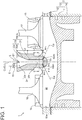
- FIG. 1 is a schematic cross-sectional view of a precombustion chamber gas engine 1 according to an embodiment of the present invention.
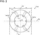
- FIG. 2 is a schematic cross-sectional view of a precombustion chamber gas engine 1 taken along line aa in FIG. 1 and shows a cross-section of a precombustion-chamber forming portion 3 according to an embodiment of the present invention.
- FIG. 3 shows a nozzle hole 4 including a precombustion-chamber-side linear hole portion 42 and a main-chamber-side linear hole portion 43 according to an embodiment of the present invention.
- FIG. 1 is a schematic cross-sectional view of a precombustion chamber gas engine 1 according to an embodiment of the present invention.
- FIG. 2 is a schematic cross-sectional view of a precombustion chamber gas engine 1 taken along line aa in FIG. 1 and shows a cross-section of a precombustion-chamber forming portion 3 according to an embodiment of the present invention.
- FIG. 3 shows a
- FIG. 4 is a diagram of a nozzle hole 4 including a precombustion-chamber-side curved hole portion 44, a connection curved hole portion 45, and a main-chamber-side curved hole portion 46 all having the same curvature R according to an embodiment of the present invention.
- FIG. 5 is a diagram of a nozzle hole 4 including a precombustion-chamber-side curved hole portion 44, a connection curved hole portion 45, and a main-chamber-side curved hole portion 46 having different curvatures R according to an embodiment of the present invention.
- FIG. 6A is a bird's eye view of a precombustion chamber 3r having the nozzle hole 4 shown in FIG. 5 .
- FIG. 6B is an enlarged view of FIG. 6A .
- FIG. 7 shows a nozzle hole 4 according to an embodiment of the present invention.
- the precombustion chamber gas engine 1 includes a main-chamber forming portion 2 forming a main combustion chamber 2r of an engine, a precombustion-chamber forming portion 3 forming a precombustion chamber 3r, an ignition device 5, and a precombustion-chamber-gas supply device 6.
- the precombustion chamber gas engine 1 includes: a cylinder 13 including a cylinder block 11 having therein a cylinder structure of cylindrical shape and a cylinder head 12 having therein a recessed structure capable of capping the top of the cylinder structure; a piston 14 reciprocably disposed in the cylinder 13; an intake port 15 and an exhaust port 16 connected around the cylinder head 12; an intake valve 17 for opening and closing the intake port 15; an exhaust valve 18 for opening and closing the exhaust port 16; and a precombustion chamber cap 19.
- a main combustion chamber 2r main chamber is defined between the cylinder 13 and the piston 14.
- a precombustion chamber 3r is formed by the precombustion chamber cap 19 disposed on the cylinder head 12 so as to be positioned above the main combustion chamber 2r (opposite to the piston 14). That is, in the embodiments shown in FIGs. 1 to 7 , the cylinder 13 and the piston 14 form the main-chamber forming portion 2 and the precombustion chamber cap 19 forms the precombustion-chamber forming portion 3.
- the precombustion-chamber forming portion 3 includes a plurality of nozzle holes 4 connecting the precombustion chamber 3r formed in the precombustion-chamber forming portion 3 to the outside.
- the main combustion chamber 2r communicates with the precombustion chamber 3r via the plurality of nozzle holes 4. More specifically, each of the nozzle holes 4 has a main-chamber-side opening 41m facing the main combustion chamber 2r on one side and a precombustion-chamber-side opening 41s facing the precombustion chamber 3r on the other side.
- a precombustion-chamber-side opening end 42s is connected to a bottom portion 35 including a portion furthest from the top portion where an ignition portion 51 is disposed.
- the plurality of nozzle holes 4 may be arranged around the central axis of the precombustion chamber 3r (hereinafter, precombustion chamber central axis Cs) at an equal interval, and each of the nozzle holes 4 may extend linearly, in a plan view.
- the cross-sectional shape (shape in plan view) of the precombustion-chamber forming portion 3 (precombustion chamber cap 19) having the precombustion chamber central axis Cs as a normal is circular, and the precombustion-chamber forming portion 3 has, for instance, six linear nozzle holes 4.
- the nozzle holes 4 are arranged at an equal interval of 60° around the precombustion chamber central axis Cs and each of the nozzle holes 4 extends along the radial direction. Further, each of the nozzle holes extends at a predetermined angle of depression.
- the angle of depression of the nozzle hole 4 is an angle between a line perpendicular to the central axis of the main combustion chamber 2r (hereinafter, main chamber central axis Cm) and a main-chamber-side straight line Tm (described later) of the nozzle hole 4 and is represented by the main-chamber-side angle ⁇ m in the embodiments shown in FIGs. 1 to 7 .
- the precombustion-chamber forming portion 3 includes a small-diameter-cylinder forming portion 31 which forms a small-diameter cylinder chamber 31r having a predetermined inner diameter and connected to the plurality of nozzle holes 4 and a large-diameter-cylinder forming portion 33 which forms a large-diameter cylinder chamber 33r having an inner diameter larger than that of the small-diameter cylinder chamber 31r. That is, the precombustion chamber 3r includes a small-diameter cylinder chamber 31r and a large-diameter cylinder chamber 33r.
- the large-diameter cylinder chamber 33r includes an enlarged diameter cylinder portion 33d connected to the small-diameter cylinder chamber 31r and having an inner diameter increasing with a distance from the small-diameter cylinder chamber 31r and a cylindrical constant diameter cylinder portion 33c connected to the enlarged diameter cylinder portion 33d and having an inner diameter equal to the maximum diameter of the enlarged diameter cylinder portion 33d.
- the precombustion chamber central axis Cs coincides with the central axis of the small-diameter cylinder chamber 31r.
- the present invention is not limited to the present embodiments.
- the precombustion chamber 3r may have other shape, for instance, a cylindrical shape having a constant inner diameter.
- the main chamber central axis Cm coincides with the precombustion chamber central axis Cs
- the present invention is not limited thereto.
- the main chamber central axis Cm may not coincide with the precombustion chamber central axis Cs, for instance, the precombustion chamber central axis Cs may be oblique to the main chamber central axis Cm.
- the central axis of the small-diameter cylinder chamber 31r may not coincide with the central axis of the large-diameter cylinder chamber 33r.
- the ignition device 5 is disposed in the large-diameter cylinder chamber 33r of the precombustion chamber 3r as shown in FIG. 1 . More specifically, the ignition device 5 has an ignition portion 51 capable of igniting an air-fuel mixture.
- the ignition device 5 is an ignition plug, and the ignition device 5 is disposed on an engine so that an electrode (ignition portion 51) of the ignition plug is positioned on the precombustion chamber central axis Cs.
- the present invention is not limited to the present embodiment.
- the ignition device 5 may be disposed on an engine so that the ignition portion 51 (e.g., electrode of ignition plug) is spaced from the central axis of the main combustion chamber 2r (hereinafter, main chamber central axis Cm) at a predetermined distance.
- the ignition portion 51 e.g., electrode of ignition plug
- the precombustion-chamber-gas supply device 6 directly supplies a precombustion chamber fuel gas to the precombustion chamber 3r not via the main combustion chamber 2r.
- the precombustion-chamber-gas supply device 6 is configured to supply a precombustion chamber fuel gas to the large-diameter cylinder chamber 33r, and the supply of the precombustion chamber fuel gas to the precombustion chamber 3r is controlled by a precombustion-chamber-fuel-gas supply valve 61 (see FIG. 1 ).
- the precombustion chamber gas engine 1 having the above configuration opens the intake valve 17 and closes the exhaust valve 18 when the piston 14 moves downward at the intake stroke, for instance.
- a lean premixed gas containing a mixture of a fuel gas and air is introduced into the cylinder 13 through the intake port 15 connected to the intake valve 17.
- a precombustion chamber fuel gas is introduced into the precombustion chamber 3r.
- the precombustion-chamber-fuel-gas supply valve 61 closes when the piston 14 moves upward.
- the lean premixed gas introduced into the cylinder 13 through the intake port 15 is compressed as the piston 14 moves upward, and a part of the lean premixed gas is introduced into the precombustion chamber 3r through each of the nozzle holes 4 of the precombustion chamber 3r.
- the lean premixed gas introduced from the main combustion chamber 2r to the precombustion chamber 3r is mixed with the precombustion chamber fuel gas to produce an air-fuel mixture having a concentration suitable for ignition in the precombustion chamber 3r.
- the air-fuel mixture in the precombustion chamber 3r is ignited by the ignition device 5 at a predetermined timing when the piston 14 arrives at the vicinity of the compression top dead center, and the air-fuel mixture in the precombustion chamber 3r is thus combusted.
- a combustion flame caused by this combustion is injected into the cylinder 13 through each of the nozzle holes and ignites the lean premixed gas in the cylinder 13, which leads to combustion of the lean premixed gas in the main combustion chamber 2r.
- combustion fluctuation in the main combustion chamber 2r is greatly affected by the mixing state of the precombustion chamber fuel gas supplied to the precombustion chamber 3r by the precombustion-chamber-gas supply device 6 and the lean premixed gas flowing from the main combustion chamber 2r to the precombustion chamber 3r via the nozzle holes 4 during the compression stroke.
- the present inventors have arrived at forming the plurality of nozzle holes 4 in a later-described shape to promote mixing of fuel in the precombustion chamber 3r at the compression stroke, to suppress the combustion fluctuation in the main combustion chamber 2r at the combustion stroke, and to reduce residue of non-combusted fuel, thereby attempting to improve the efficiency.
- At least one of the plurality of nozzle holes 4 is formed so that a precombustion-chamber-side straight line Ts, which is a straight line passing through the central position Pc of the precombustion-chamber-side opening 41s of the nozzle hole 4 and parallel to the extending direction of the central line Cp of the precombustion-chamber-side opening 41s of the nozzle hole 4, intersects with a main-chamber-side straight line Tm, which is a straight line passing through the central position Pc of the main-chamber-side opening 41m of the nozzle hole 4 and parallel to the extending direction of the central line Cp of the main-chamber-side opening 41m of the nozzle hole 4, and an acute angle (precombustion-chamber-side angle cps) between the precombustion chamber central axis Cs of the precombustion chamber 3r and the precombustion-chamber-side straight line Ts is smaller than an acute angle (main-cham
- the precombustion-chamber-side straight line Ts is a tangential line of the central line Cp of the nozzle hole 4 at the central position Pc of the precombustion-chamber-side opening 41s of the nozzle hole 4
- the main-chamber-side straight line Tm is a tangential line of the central line Cp of the nozzle hole 4 at the central position Pc of the main-chamber-side opening 41m of the nozzle hole 4.
- the tangential line includes a line parallel to the central line Cp of the nozzle hole 4.
- precombustion-chamber-side straight line Ts and the main-chamber-side straight line Tm intersect at an intersection point Px, and the inclination of the precombustion-chamber-side straight line Ts to the precombustion chamber central axis Cs is larger than the inclination of the main-chamber-side straight line Tm to the precombustion chamber central axis Cs.
- the precombustion-chamber-side straight line Ts is directed to a further upper portion of the precombustion chamber 3r than the main-chamber-side straight line Tm is directed, at the time of introducing the lean premixed gas to the precombustion chamber 3r through the nozzle hole 4 thus shaped, the lean premixed gas is introduced toward a further upper portion of the precombustion chamber 3r as compared with a nozzle hole 4 in which the main-chamber-side straight line Tm coincides with the precombustion-chamber-side straight line Ts.
- the present invention is not limited thereto.
- at least one of the nozzle holes 4 is formed so that precombustion-chamber-side angle ⁇ s differs from the main-chamber-side angle cpm.
- the nozzle hole 4 in which the precombustion-chamber-side angle ⁇ s is smaller than the main-chamber-side angle ⁇ m may be formed by electrical discharge machining processing metal with sparks.
- At least one nozzle hole 4 of the plurality of nozzle holes 4 is formed so that the precombustion-chamber-side straight line Ts intersects with the main-chamber-side straight line Tm, an angle between the central line Cp of the nozzle hole 4 and the precombustion chamber central axis Cs varies between the precombustion chamber side and the main chamber side of the nozzle hole ( ⁇ m ⁇ s).
- the nozzle hole 4 is formed so that an acute angle (cps) between the precombustion chamber central axis Cs and the precombustion-chamber-side straight line Ts is smaller than an acute angle (cpm) between the precombustion chamber central axis Cs and the main-chamber-side straight line Tm, the lean premixed gas is introduced toward a further upper portion of the precombustion chamber 3r from the main combustion chamber 2r via this nozzle hole 4 at the compression stroke.
- cps an acute angle
- cpm acute angle
- At least one of the plurality of nozzle holes 4 includes a precombustion-chamber-side linear hole portion 42 and a main-chamber-side linear hole portion 43.
- the precombustion-chamber-side linear hole portion 42 is a linear portion of the nozzle hole 4 which forms the precombustion-chamber-side opening 41s at a first end of the precombustion-chamber-side linear hole portion 42.
- the main-chamber-side linear hole portion 43 is a linear portion of the nozzle hole 4 which is connected to a second end of the precombustion-chamber-side linear hole portion 42 and forms the main-chamber-side opening 41m.
- each of the precombustion-chamber-side linear hole portion 42 and the main-chamber-side linear hole portion 43 has a linear shape
- the precombustion-chamber-side straight line Ts coincides with the central line Cp of the nozzle hole 4 passing through the precombustion-chamber-side linear hole portion 42
- the main-chamber-side straight line Tm coincides with the central line Cp of the nozzle hole 4 passing through the main-chamber-side linear hole portion 43.
- At least one of the plurality of nozzle holes 4 includes a precombustion-chamber-side curved hole portion 44, a connection curved hole portion 45, and a main-chamber-side curved hole portion 46.
- the precombustion-chamber-side curved hole portion 44 is a portion of the nozzle hole 4 which has a first curvature R1 and forms the precombustion-chamber-side opening 41s at a first end of the precombustion-chamber-side curved hole portion 44.
- the main-chamber-side curved hole portion 46 is a portion of the nozzle hole 4 which has a second curvature R2 and forms the main-chamber-side opening 41m at a first end of the main-chamber-side curved hole portion 46.
- the connection curved hole portion 45 is a portion which has a third curvature R3 and has both ends respectively connected to a second end of the precombustion-chamber-side curved hole portion 44 and a second end of the main-chamber-side curved hole portion 46.
- the curvature R is the reciprocal of the radius.
- the second curvature R2 of the main-chamber-side curved hole portion 46 and the third curvature R3 of the connection curved hole portion 45 are equal to the first curvature R1 of the precombustion-chamber-side curved hole portion 44.
- the third curvature R3 of the connection curved hole portion 45 is larger than the second curvature of the main-chamber-side curved hole portion 46 (R2 ⁇ R3).
- the first curvature R1 of the precombustion-chamber-side curved hole portion 44 is larger than the third curvature R3 of the connection curved hole portion 45 (R1>R3).
- the nozzle hole 4 having the shape as shown in FIGs. 5 to 6B may have the first curvature R1 equal to the third curvature R3, and the nozzle hole 4 having the shape as shown in FIG. 7 may have the first curvature R1 larger than the third curvature R3, of course.
- at least one curvature of the first curvature R1, the second curvature R2, or the third curvature R3 may be infinite, for instance, the third curvature R3 may be infinite so that the corresponding curved portion has a linear shape.
- an acute angle (precombustion-chamber-side angle cps) between the precombustion chamber central axis Cs and the precombustion-chamber-side straight line Ts is smaller than an acute angle (main-chamber-side angle cpm) between the precombustion chamber central axis Cs and the main-chamber-side straight line Tm.
- the main-chamber-side angle ⁇ m of all the nozzle holes 4 may be the same, or the main-chamber-side angle ⁇ m of at least one of the nozzle holes 4 may be different from those of the other nozzle holes 4. That is, by setting the main-chamber-side angle ⁇ m of each of the nozzle holes 4 appropriately, it is possible to reduce residue of non-combusted fuel in the main combustion chamber 2r, and it is possible suppress knocking and reduce heat loss. Thus, it is possible to improve the efficiency.
- each of the nozzle holes 4 may be formed so that the precombustion-chamber-side openings 41s of the plurality of nozzle holes 4 are positioned at an equal interval in a plan view while the main-chamber-side openings 41m of the plurality of nozzle holes 4 are positioned at an unequal interval in a plan view. That is, by setting the position of the main-chamber-side opening 41m of each of the nozzle holes 4 appropriately, it is possible to reduce residue of non-combusted fuel in the main combustion chamber 2r, and it is possible suppress knocking and reduce heat loss. Thus, it is possible to improve the efficiency.
- an acute angle (precombustion-chamber-side angle cps) between the central line Cp of the precombustion chamber 3r and the precombustion-chamber-side straight line Ts may be 0° or more and 65° or less (0° ⁇ s ⁇ 65°).
- the precombustion-chamber-side angle ⁇ s can be easily brought close to 0 degrees.
- the sum of the cross-sectional areas S2 of the plurality of nozzle holes 4 can be brought close to the cross-sectional area S1 of the small-diameter cylinder chamber 31r (S1 ⁇ S2), and thus it is possible to reduce pressure loss caused when the lean premixed gas or the combustion flame passes through the nozzle hole 4.
- an acute angle between the main chamber central axis Cm and the main-chamber-side straight line Tm may be 65° or more and 80° or less.
- the main-chamber-side angle ⁇ m is 65° or more and 80° or less (65° ⁇ m ⁇ 80°).
- the length L1 of the small-diameter cylinder chamber 31r is longer than the length L2 of the large-diameter cylinder chamber 33r (L1>L2) (see FIG. 1 ).
- L1>L2 the length L1 of the small-diameter cylinder chamber 31r
- the distance from the precombustion-chamber-side opening 41s formed in the vicinity of the bottom portion 35 of the precombustion chamber 3r to the ignition portion 51 increases. This tends to prevent appropriate mixing of the precombustion chamber fuel gas and the lean premixed gas coming from the main combustion chamber 2r.
- the lean premixed gas introduced from the main combustion chamber is directed to a further upper portion of the precombustion chamber fuel, it is possible to promote mixing of fuel in the precombustion chamber at the compression stroke even if the length of the small-diameter cylinder chamber 31r increases.
- the present invention is not limited to the embodiments described above, but includes modifications to the embodiments described above, and embodiments composed of combinations of those embodiments.
Landscapes
- Engineering & Computer Science (AREA)
- Chemical & Material Sciences (AREA)
- Combustion & Propulsion (AREA)
- Mechanical Engineering (AREA)
- General Engineering & Computer Science (AREA)
- Combustion Methods Of Internal-Combustion Engines (AREA)
Abstract
Description
- The present disclosure relates to a precombustion chamber gas engine for combusting an air-fuel mixture in a main combustion chamber (main chamber) by injecting a combustion flame generated in a precombustion chamber (auxiliary chamber) via a plurality of nozzle holes to the main combustion chamber.
- A precombustion chamber gas engine is conventionally known as an engine enabling efficient combustion of a lean premixed gas (for instance,
Patent Documents 1 to 3). The precombustion chamber gas engine includes a main combustion chamber (main chamber) defined between a piston and a cylinder head and a precombustion chamber disposed adjacent to the main combustion chamber, for instance above the cylinder. The main combustion chamber communicates with the precombustion chamber via a plurality of nozzle holes. By igniting an air-fuel mixture in the precombustion chamber by an ignition device such as an ignition plug, a combustion flame is generated and jetted via each of the nozzle holes disposed at a lower portion of the precombustion chamber, by which a lean premixed gas in the main combustion chamber is combusted. More specifically, a part of a lean premixed gas introduced into the cylinder during the intake stroke of the engine flows into the precombustion chamber via each of the nozzle holes during the compression stroke and is mixed with a precombustion chamber fuel supplied to the precombustion chamber by a precombustion-chamber-gas supply device to produce an air-fuel mixture having a concentration suitable for ignition in the precombustion chamber. The air-fuel mixture in this state is ignited by the ignition device, and the combustion flame thereof is injected from the precombustion chamber to the cylinder and serves as a torch to ignite and combust the lean premixed gas in the main combustion chamber. This allows combustion of the lean fuel in the main combustion chamber, thus enabling low fuel consumption (high efficiency). Further, since combustion of the lean mixed gas in the main combustion chamber is performed at a relatively low temperature, generation of NOx is reduced, and low pollution can be achieved. - In such a precombustion chamber gas engine, if the flow of mixed gas from the main chamber to the precombustion chamber via the nozzle holes becomes unstable, an air-fuel mixture having a concentration suitable for ignition is less likely to be formed around an ignition portion of the ignition device (e.g., an electrode of an ignition plug), which may cause unstable combustion in the precombustion chamber. To solve the above problem, on the basis of findings that the shape of the nozzle hole affects the stability of the flow of mixed gas to be introduced into the precombustion chamber,
Patent Document 1 defines the shape of a throat (small-diameter cylinder chamber described later) of the precombustion chamber and the shape of a round-chamfered portion along a rim of a throat-side opening end of the nozzle hole to suppress combustion fluctuation. - Further, as described above, since the air-fuel mixture in the main combustion chamber is ignited by the combustion flame (torch jet) injected from the precombustion chamber to the main combustion chamber via each of the nozzle holes at the combustion stroke, variation of propagation of combustion flame of the air-fuel mixture in the main combustion chamber may cause abnormal combustion such as knocking. To solve the above problem, on the basis of findings that the variation of flame propagation speed in the main combustion chamber is caused when the temperature of a cylinder wall surface in an intake region where an intake port is located is lower than the temperature of a cylinder wall surface in an exhaust region where an exhaust port is located,
Patent Document 2 discloses that the sum of nozzle hole areas of intake-side nozzle holes disposed in the intake region is made larger than the sum of nozzle hole areas of exhaust-side nozzle holes disposed in the exhaust region. This intends to shorten the time for the flame of an intake-side air-fuel mixture ignited by the torch jet from the intake-side nozzle holes to reach the cylinder wall surface, in order to suppress the occurrence of knocking. -
Patent Document 3 discloses an ignition device included in a precombustion chamber gas engine not equipped with the above-described precombustion-chamber-gas supply device. More specifically, it discloses an ignition device capable of injecting an air-fuel mixture combusted as flame to the precombustion chamber from openings of an end cap of the ignition plug by increasing the pressure inside the end cap without fuel enrichment or fuel supply into the igniter or the precombustion chamber.Patent Document 3 discloses a nozzle hole having curvature which communicates with the precombustion chamber via a central passage. This central passage nozzles an incoming cool, fresh air-fuel mixture into a central high-velocity flow. The central high-velocity flow impinges on the end cap and displaces residual combustion gases away from the front of the ignition plug and openings of the end cap to supply the cool, fresh air/fuel mixture into the end cap. -
- Patent Document 1:
JP2016-3608A - Patent Document 2:
JP2014-62484A - Patent Document 3:
JP2015-528875A - In a precombustion chamber gas engine, combustion fluctuation in the main combustion chamber is greatly affected by the mixing state of a precombustion chamber fuel supplied to the precombustion chamber by a precombustion-chamber-gas supply device and a lean premixed gas flowing from the main combustion chamber to the precombustion chamber via nozzle holes during the compression stroke. Since combustion fluctuation in the main combustion chamber affects the efficiency of an engine, it is desired to reduce the combustion fluctuation.
-
Patent Document 3 described above relates to a precombustion chamber gas engine not equipped with a precombustion-chamber-gas supply device and does not mix a lean premixed gas flowing from the main combustion chamber to the precombustion chamber and a precombustion chamber fuel. Thus, the above-described problem is not raised. Further, the nozzle hole and the central passage are configured to introduce an air-fuel mixture into the end cap. - In view of the above, an object of at least one embodiment of the present invention is to provide a precombustion chamber gas engine capable of sufficiently mixing a lean premixed gas and a precombustion chamber fuel in a precombustion chamber.
-
- (1) According to at least one embodiment of the present invention, a precombustion chamber gas engine comprises: a main-chamber forming portion forming a main combustion chamber of an engine; a precombustion-chamber forming portion forming a precombustion chamber including a small-diameter cylinder chamber and a large-diameter cylinder chamber, the small-diameter cylinder chamber communicating with the main combustion chamber via a plurality of nozzle holes and having a predetermined inner diameter, the large-diameter cylinder chamber having an inner diameter larger than that of the small-diameter cylinder chamber; an ignition device disposed in the large-diameter cylinder chamber of the precombustion chamber; and a precombustion-chamber-gas supply device for supplying a precombustion chamber fuel gas to the precombustion chamber not via the main combustion chamber. At least one nozzle hole of the plurality of nozzle holes is formed so that: a precombustion-chamber-side straight line which is a straight line passing through a central position of a precombustion-chamber-side opening of the at least one nozzle hole and parallel to an extending direction of a central line of the precombustion-chamber-side opening of the at least one nozzle hole intersects with a main-chamber-side straight line which is a straight line passing through a central position of a main-chamber-side opening of the at least one nozzle hole and parallel to an extending direction of a central line of the main-chamber-side opening of the at least one nozzle hole; and an acute angle between a precombustion chamber central axis of the precombustion chamber and the precombustion-chamber-side straight line is smaller than an acute angle between the precombustion chamber central axis and the main-chamber-side straight line.
With the above configuration (1), since at least one nozzle hole of the plurality of nozzle holes is formed so that the precombustion-chamber-side straight line intersects with the main-chamber-side straight line, an angle between the central line of the nozzle hole and the precombustion chamber central axis varies between the precombustion chamber side and the main chamber side of the nozzle hole. Further, since the nozzle hole is formed so that an acute angle between the precombustion chamber central axis and the precombustion-chamber-side straight line is smaller than an acute angle between the precombustion chamber central axis and the main-chamber-side straight line, the lean premixed gas is introduced toward a further upper portion of the precombustion chamber from the main combustion chamber via this nozzle hole at the compression stroke. Here, at the time of introducing the lean premixed gas from the precombustion-chamber-side opening to the precombustion chamber, as the inflow direction of the lean premixed gas is directed to an upper portion of the precombustion chamber, mixing of the precombustion chamber fuel gas supplied to the precombustion chamber by the precombustion-chamber-gas supply device and the lean premixed gas incoming from the main combustion chamber is promoted. On the other hand, at the time of injecting the combustion flame ignited in the precombustion chamber to the main combustion chamber via the nozzle hole, as the angle of depression decreases, variation of flame propagation in the main combustion chamber is suppressed, and the combustion fluctuation is suppressed. Thus, with the above configuration, it is possible to promote mixing of fuel in the precombustion chamber at the compression stroke, and it is possible to suppress the combustion fluctuation in the main combustion chamber at the combustion stroke by setting the main-chamber-side angle appropriately for suppressing the variation of flame propagation in the main combustion chamber. - (2) In some embodiments, in the above configuration (1), the at least one nozzle hole of the plurality of nozzle holes includes: a precombustion-chamber-side linear hole portion of linear shape forming the precombustion-chamber-side opening at a first end of the precombustion-chamber-side linear hole portion; and a main-chamber-side linear hole portion of linear shape connected to a second end of the precombustion-chamber-side linear hole portion and forming the main-chamber-side opening.
With the above configuration (2), by forming at least one of the plurality of nozzle holes so as to connect the precombustion-chamber-side linear hole portion and the main-chamber-side linear hole portion each having a linear shape, it is possible to form the nozzle hole in which an acute angle between the precombustion chamber central axis and the precombustion-chamber-side straight line is smaller than an acute angle between the precombustion chamber central axis and the main-chamber-side straight line. - (3) In some embodiments, in the above configuration (1), the at least one nozzle hole of the plurality of nozzle holes includes: a precombustion-chamber-side curved hole portion having a first curvature and forming the precombustion-chamber-side opening at a first end of the precombustion-chamber-side curved hole portion; a main-chamber-side curved hole portion having a second curvature and forming the main-chamber-side opening at a first end of the main-chamber-side curved hole portion; and a connection curved hole portion having a third curvature and connected to a second end of the precombustion-chamber-side curved hole portion and to a second end of the main-chamber-side curved hole portion.
With the above configuration (3), by forming at least one of the plurality of nozzle holes so as to connect the precombustion-chamber-side curved hole portion, the connection curved hole portion, and the main-chamber-side curved hole portion each having an arc shape, it is possible to reduce resistance when the lean premixed gas passes through the nozzle hole at the compression stroke or when the combustion flame passes through the nozzle hole at the combustion stroke. Thus, it is possible to suppress combustion fluctuation in the main combustion chamber at the combustion stroke, while promoting mixing of fuel in the precombustion chamber at the compression stroke, as described above. - (4) In some embodiments, in the above configuration (3), the first curvature, the second curvature, and the third curvature are equal to each other.
With the above configuration (4), since at least one of the plurality of nozzle holes is shaped so as to have a constant curvature, it is possible to reduce resistance when the lean premixed gas passes through the nozzle hole at the compression stroke or when the combustion flame passes through the nozzle hole at the combustion stroke. - (5) In some embodiments, in the above configuration (3), the third curvature is larger than the second curvature, and the first curvature is equal to or larger than the third curvature.
With the above configuration (5), since at least one of the plurality of nozzle holes is shaped so that the curvature is changed, it is possible to reduce resistance when the lean premixed gas passes through the nozzle hole at the compression stroke or when the combustion flame passes through the nozzle hole at the combustion stroke. - (6) In some embodiments, in any one of the above configurations (1) to (5), an acute angle between a central line of the precombustion chamber and the precombustion-chamber-side straight line is 0° or more and 65° or less.
With the above configuration (6), at the time of introducing the lean premixed gas from the precombustion-chamber-side opening to the precombustion chamber, it is possible to sufficiently promote mixing of the precombustion chamber fuel gas supplied to the precombustion chamber by the precombustion-chamber-gas supply device and the lean premixed gas incoming from the main combustion chamber. - (7) In some embodiments, in any one of the above configurations (1) to (6), an acute angle between a main chamber central axis of the main combustion chamber and the main-chamber-side straight line is 65° or more and 80° or less.
With the above configuration (7), at the time of injecting the combustion flame ignited in the precombustion chamber to the main combustion chamber via the nozzle hole, it is possible to sufficiently suppress variation of flame propagation in the main combustion chamber. - (8) In some embodiments, in any one of the above configurations (1) to (7), a length of the small-diameter cylinder chamber is longer than a length of the large-diameter cylinder chamber.
- With the above configuration (8), even when the length of the small-diameter cylinder chamber is long, by introducing the lean premixed gas from the main combustion chamber to a further upper portion of the precombustion chamber, it is possible to promote mixing of fuel in the precombustion chamber at the compression stroke.
- According to at least one embodiment of the present invention, there is provided a precombustion chamber gas engine capable of sufficiently mixing a lean premixed gas and a precombustion chamber fuel in a precombustion chamber.
-
-
FIG. 1 is a schematic cross-sectional view of a precombustion chamber gas engine according to an embodiment of the present invention. The figure shows a case where the cross-sectional area of a specific near nozzle hole is smaller than the cross-sectional area of a specific far nozzle hole. -
FIG. 2 is a schematic cross-sectional view of a precombustion chamber gas engine taken along line aa inFIG. 1 and shows a cross-section of a precombustion-chamber forming portion according to an embodiment of the present invention. -
FIG. 3 shows a nozzle hole including a precombustion-chamber-side linear hole portion and a main-chamber-side linear hole portion according to an embodiment of the present invention. -
FIG. 4 is a diagram of a nozzle hole including a precombustion-chamber-side curved hole portion, a connection curved hole portion, and a main-chamber-side curved hole portion all having the same curvature according to an embodiment of the present invention. -
FIG. 5 is a diagram of a nozzle hole including a precombustion-chamber-side curved hole portion, a connection curved hole portion, and a main-chamber-side curved hole portion having different curvatures according to an embodiment of the present invention. -
FIG. 6A is a bird's eye view of a precombustion chamber having the nozzle hole shown inFIG. 5 . -
FIG. 6B is an enlarged view ofFIG. 6A . -
FIG. 7 shows a nozzle hole according to another embodiment of the present invention. - Embodiments of the present invention will now be described in detail with reference to the accompanying drawings. It is intended, however, that unless particularly identified, dimensions, materials, shapes, relative positions and the like of components described in the embodiments shall be interpreted as illustrative only and not intended to limit the scope of the present invention.
- For instance, an expression of relative or absolute arrangement such as "in a direction", "along a direction", "parallel", "orthogonal", "centered", "concentric" and "coaxial" shall not be construed as indicating only the arrangement in a strict literal sense, but also includes a state where the arrangement is relatively displaced by a tolerance, or by an angle or a distance whereby it is possible to achieve the same function.
- For instance, an expression of an equal state such as "same" "equal" and "uniform" shall not be construed as indicating only the state in which the feature is strictly equal, but also includes a state in which there is a tolerance or a difference that can still achieve the same function.
- Further, for instance, an expression of a shape such as a rectangular shape or a cylindrical shape shall not be construed as only the geometrically strict shape, but also includes a shape with unevenness or chamfered corners within the range in which the same effect can be achieved.
- On the other hand, an expression such as "comprise", "include", "have", "contain" and "constitute" are not intended to be exclusive of other components.
-
FIG. 1 is a schematic cross-sectional view of a precombustionchamber gas engine 1 according to an embodiment of the present invention.FIG. 2 is a schematic cross-sectional view of a precombustionchamber gas engine 1 taken along line aa inFIG. 1 and shows a cross-section of a precombustion-chamber forming portion 3 according to an embodiment of the present invention.FIG. 3 shows anozzle hole 4 including a precombustion-chamber-sidelinear hole portion 42 and a main-chamber-sidelinear hole portion 43 according to an embodiment of the present invention.FIG. 4 is a diagram of anozzle hole 4 including a precombustion-chamber-sidecurved hole portion 44, a connectioncurved hole portion 45, and a main-chamber-sidecurved hole portion 46 all having the same curvature R according to an embodiment of the present invention.FIG. 5 is a diagram of anozzle hole 4 including a precombustion-chamber-sidecurved hole portion 44, a connectioncurved hole portion 45, and a main-chamber-sidecurved hole portion 46 having different curvatures R according to an embodiment of the present invention.FIG. 6A is a bird's eye view of aprecombustion chamber 3r having thenozzle hole 4 shown inFIG. 5 .FIG. 6B is an enlarged view ofFIG. 6A .FIG. 7 shows anozzle hole 4 according to an embodiment of the present invention. - As shown in
FIGs. 1 to 7 , the precombustionchamber gas engine 1 includes a main-chamber forming portion 2 forming amain combustion chamber 2r of an engine, a precombustion-chamber forming portion 3 forming aprecombustion chamber 3r, anignition device 5, and a precombustion-chamber-gas supply device 6. - Hereinafter, each of the components of the precombustion
chamber gas engine 1 will be described. - As shown in
FIG. 1 , the precombustionchamber gas engine 1 includes: acylinder 13 including acylinder block 11 having therein a cylinder structure of cylindrical shape and acylinder head 12 having therein a recessed structure capable of capping the top of the cylinder structure; apiston 14 reciprocably disposed in thecylinder 13; anintake port 15 and anexhaust port 16 connected around thecylinder head 12; anintake valve 17 for opening and closing theintake port 15; anexhaust valve 18 for opening and closing theexhaust port 16; and aprecombustion chamber cap 19. Amain combustion chamber 2r (main chamber) is defined between thecylinder 13 and thepiston 14. On the other hand, in the embodiments shown inFIGs. 1 to 7 , aprecombustion chamber 3r is formed by theprecombustion chamber cap 19 disposed on thecylinder head 12 so as to be positioned above themain combustion chamber 2r (opposite to the piston 14). That is, in the embodiments shown inFIGs. 1 to 7 , thecylinder 13 and thepiston 14 form the main-chamber forming portion 2 and theprecombustion chamber cap 19 forms the precombustion-chamber forming portion 3. - As shown in
FIGs. 1 to 7 , the precombustion-chamber forming portion 3 includes a plurality ofnozzle holes 4 connecting theprecombustion chamber 3r formed in the precombustion-chamber forming portion 3 to the outside. Themain combustion chamber 2r communicates with theprecombustion chamber 3r via the plurality of nozzle holes 4. More specifically, each of the nozzle holes 4 has a main-chamber-side opening 41m facing themain combustion chamber 2r on one side and a precombustion-chamber-side opening 41s facing theprecombustion chamber 3r on the other side. A precombustion-chamber-side opening end 42s is connected to abottom portion 35 including a portion furthest from the top portion where anignition portion 51 is disposed. As shown inFIG. 2 , the plurality ofnozzle holes 4 may be arranged around the central axis of theprecombustion chamber 3r (hereinafter, precombustion chamber central axis Cs) at an equal interval, and each of the nozzle holes 4 may extend linearly, in a plan view. In the example ofFIG. 2 , the cross-sectional shape (shape in plan view) of the precombustion-chamber forming portion 3 (precombustion chamber cap 19) having the precombustion chamber central axis Cs as a normal is circular, and the precombustion-chamber forming portion 3 has, for instance, six linear nozzle holes 4. The nozzle holes 4 (main-chamber-side openings 41m and precombustion-chamber-side openings 41s) are arranged at an equal interval of 60° around the precombustion chamber central axis Cs and each of the nozzle holes 4 extends along the radial direction. Further, each of the nozzle holes extends at a predetermined angle of depression. The angle of depression of thenozzle hole 4 is an angle between a line perpendicular to the central axis of themain combustion chamber 2r (hereinafter, main chamber central axis Cm) and a main-chamber-side straight line Tm (described later) of thenozzle hole 4 and is represented by the main-chamber-side angle ϕm in the embodiments shown inFIGs. 1 to 7 . - Further, the precombustion-
chamber forming portion 3 includes a small-diameter-cylinder forming portion 31 which forms a small-diameter cylinder chamber 31r having a predetermined inner diameter and connected to the plurality ofnozzle holes 4 and a large-diameter-cylinder forming portion 33 which forms a large-diameter cylinder chamber 33r having an inner diameter larger than that of the small-diameter cylinder chamber 31r. That is, theprecombustion chamber 3r includes a small-diameter cylinder chamber 31r and a large-diameter cylinder chamber 33r. Further, the large-diameter cylinder chamber 33r includes an enlargeddiameter cylinder portion 33d connected to the small-diameter cylinder chamber 31r and having an inner diameter increasing with a distance from the small-diameter cylinder chamber 31r and a cylindrical constantdiameter cylinder portion 33c connected to the enlargeddiameter cylinder portion 33d and having an inner diameter equal to the maximum diameter of the enlargeddiameter cylinder portion 33d. Further, the precombustion chamber central axis Cs coincides with the central axis of the small-diameter cylinder chamber 31r. However, the present invention is not limited to the present embodiments. In some embodiments, theprecombustion chamber 3r may have other shape, for instance, a cylindrical shape having a constant inner diameter. Further, although in the embodiment shown inFIG. 1 , the main chamber central axis Cm coincides with the precombustion chamber central axis Cs, the present invention is not limited thereto. In some embodiments, the main chamber central axis Cm may not coincide with the precombustion chamber central axis Cs, for instance, the precombustion chamber central axis Cs may be oblique to the main chamber central axis Cm. Further, the central axis of the small-diameter cylinder chamber 31r may not coincide with the central axis of the large-diameter cylinder chamber 33r. - The
ignition device 5 is disposed in the large-diameter cylinder chamber 33r of theprecombustion chamber 3r as shown inFIG. 1 . More specifically, theignition device 5 has anignition portion 51 capable of igniting an air-fuel mixture. In the embodiment shown inFIG. 1 , theignition device 5 is an ignition plug, and theignition device 5 is disposed on an engine so that an electrode (ignition portion 51) of the ignition plug is positioned on the precombustion chamber central axis Cs. However, the present invention is not limited to the present embodiment. Theignition device 5 may be disposed on an engine so that the ignition portion 51 (e.g., electrode of ignition plug) is spaced from the central axis of themain combustion chamber 2r (hereinafter, main chamber central axis Cm) at a predetermined distance. - The precombustion-chamber-gas supply device 6 directly supplies a precombustion chamber fuel gas to the
precombustion chamber 3r not via themain combustion chamber 2r. In the embodiment shown inFIG. 1 , the precombustion-chamber-gas supply device 6 is configured to supply a precombustion chamber fuel gas to the large-diameter cylinder chamber 33r, and the supply of the precombustion chamber fuel gas to theprecombustion chamber 3r is controlled by a precombustion-chamber-fuel-gas supply valve 61 (seeFIG. 1 ). - The precombustion
chamber gas engine 1 having the above configuration opens theintake valve 17 and closes theexhaust valve 18 when thepiston 14 moves downward at the intake stroke, for instance. As theintake valve 17 opens, a lean premixed gas containing a mixture of a fuel gas and air is introduced into thecylinder 13 through theintake port 15 connected to theintake valve 17. As the precombustion-chamber-fuel-gas supply valve 61 opens, a precombustion chamber fuel gas is introduced into theprecombustion chamber 3r. Furthermore, at the compression stroke, the precombustion-chamber-fuel-gas supply valve 61 closes when thepiston 14 moves upward. Further, the lean premixed gas introduced into thecylinder 13 through theintake port 15 is compressed as thepiston 14 moves upward, and a part of the lean premixed gas is introduced into theprecombustion chamber 3r through each of the nozzle holes 4 of theprecombustion chamber 3r. The lean premixed gas introduced from themain combustion chamber 2r to theprecombustion chamber 3r is mixed with the precombustion chamber fuel gas to produce an air-fuel mixture having a concentration suitable for ignition in theprecombustion chamber 3r. The air-fuel mixture in theprecombustion chamber 3r is ignited by theignition device 5 at a predetermined timing when thepiston 14 arrives at the vicinity of the compression top dead center, and the air-fuel mixture in theprecombustion chamber 3r is thus combusted. A combustion flame caused by this combustion is injected into thecylinder 13 through each of the nozzle holes and ignites the lean premixed gas in thecylinder 13, which leads to combustion of the lean premixed gas in themain combustion chamber 2r. - In this regard, in the precombustion
chamber gas engine 1, combustion fluctuation in themain combustion chamber 2r is greatly affected by the mixing state of the precombustion chamber fuel gas supplied to theprecombustion chamber 3r by the precombustion-chamber-gas supply device 6 and the lean premixed gas flowing from themain combustion chamber 2r to theprecombustion chamber 3r via the nozzle holes 4 during the compression stroke. Further, at the time of introducing the lean premixed gas from the precombustion-chamber-side opening 41s to theprecombustion chamber 3r, as the inflow direction of the lean premixed gas is directed to an upper portion of theprecombustion chamber 3r, mixing of the precombustion chamber fuel gas supplied to theprecombustion chamber 3r by the precombustion-chamber-gas supply device 6 and the lean premixed gas incoming from themain combustion chamber 2r is promoted. On the other hand, at the time of injecting the combustion flame ignited in theprecombustion chamber 3r to themain combustion chamber 2r via thenozzle hole 4, as the angle of depression decreases, variation of flame propagation in themain combustion chamber 2r is suppressed, and the combustion fluctuation is suppressed. In view of this, the present inventors have arrived at forming the plurality ofnozzle holes 4 in a later-described shape to promote mixing of fuel in theprecombustion chamber 3r at the compression stroke, to suppress the combustion fluctuation in themain combustion chamber 2r at the combustion stroke, and to reduce residue of non-combusted fuel, thereby attempting to improve the efficiency. - More specifically, as shown in
FIGs. 3 to 7 , at least one of the plurality ofnozzle holes 4 is formed so that a precombustion-chamber-side straight line Ts, which is a straight line passing through the central position Pc of the precombustion-chamber-side opening 41s of thenozzle hole 4 and parallel to the extending direction of the central line Cp of the precombustion-chamber-side opening 41s of thenozzle hole 4, intersects with a main-chamber-side straight line Tm, which is a straight line passing through the central position Pc of the main-chamber-side opening 41m of thenozzle hole 4 and parallel to the extending direction of the central line Cp of the main-chamber-side opening 41m of thenozzle hole 4, and an acute angle (precombustion-chamber-side angle cps) between the precombustion chamber central axis Cs of theprecombustion chamber 3r and the precombustion-chamber-side straight line Ts is smaller than an acute angle (main-chamber-side angle cpm) between the precombustion chamber central axis Cs and the main-chamber-side straight line Tm (ϕs<ϕm). - In brief, the precombustion-chamber-side straight line Ts is a tangential line of the central line Cp of the
nozzle hole 4 at the central position Pc of the precombustion-chamber-side opening 41s of thenozzle hole 4, and the main-chamber-side straight line Tm is a tangential line of the central line Cp of thenozzle hole 4 at the central position Pc of the main-chamber-side opening 41m of thenozzle hole 4. Herein, the tangential line includes a line parallel to the central line Cp of thenozzle hole 4. Further, the precombustion-chamber-side straight line Ts and the main-chamber-side straight line Tm intersect at an intersection point Px, and the inclination of the precombustion-chamber-side straight line Ts to the precombustion chamber central axis Cs is larger than the inclination of the main-chamber-side straight line Tm to the precombustion chamber central axis Cs. That is, since the precombustion-chamber-side straight line Ts is directed to a further upper portion of theprecombustion chamber 3r than the main-chamber-side straight line Tm is directed, at the time of introducing the lean premixed gas to theprecombustion chamber 3r through thenozzle hole 4 thus shaped, the lean premixed gas is introduced toward a further upper portion of theprecombustion chamber 3r as compared with anozzle hole 4 in which the main-chamber-side straight line Tm coincides with the precombustion-chamber-side straight line Ts. As a result, it is possible to promote mixing of the precombustion chamber fuel gas in theprecombustion chamber 3r and the lean premixed gas incoming from themain combustion chamber 2r. Further, at this time, by setting the main-chamber-side angle ϕm appropriately for suppressing the variation of flame propagation in themain combustion chamber 2r, it is possible to suppress the combustion fluctuation in themain combustion chamber 2r. - Although in the embodiments shown in
FIGs. 1 to 7 , all of the plurality ofnozzle holes 4 have the same shape, the present invention is not limited thereto. In some embodiments, as described above, at least one of the nozzle holes 4 is formed so that precombustion-chamber-side angle ϕs differs from the main-chamber-side angle cpm. Further, thenozzle hole 4 in which the precombustion-chamber-side angle ϕs is smaller than the main-chamber-side angle ϕm may be formed by electrical discharge machining processing metal with sparks. - With the above configuration, since at least one
nozzle hole 4 of the plurality ofnozzle holes 4 is formed so that the precombustion-chamber-side straight line Ts intersects with the main-chamber-side straight line Tm, an angle between the central line Cp of thenozzle hole 4 and the precombustion chamber central axis Cs varies between the precombustion chamber side and the main chamber side of the nozzle hole (ϕm≠ϕs). Further, since thenozzle hole 4 is formed so that an acute angle (cps) between the precombustion chamber central axis Cs and the precombustion-chamber-side straight line Ts is smaller than an acute angle (cpm) between the precombustion chamber central axis Cs and the main-chamber-side straight line Tm, the lean premixed gas is introduced toward a further upper portion of theprecombustion chamber 3r from themain combustion chamber 2r via thisnozzle hole 4 at the compression stroke. Thus, it is possible to promote mixing of fuel in theprecombustion chamber 3r at the compression stroke, and it is possible to suppress the combustion fluctuation in the main combustion chamber at the combustion stroke by setting the main-chamber-side angle ϕm appropriately for suppressing the variation of flame propagation in themain combustion chamber 2r. Further, by setting the angle appropriately for reducing residue of non-combusted fuel in themain combustion chamber 2r, it is possible to suppress knocking and reduce heat loss. - Next, a specific shape of the
nozzle hole 4 will be described with reference toFIGs. 3 to 7 . - In some embodiments, as shown in
FIG. 3 , at least one of the plurality ofnozzle holes 4 includes a precombustion-chamber-sidelinear hole portion 42 and a main-chamber-sidelinear hole portion 43. The precombustion-chamber-sidelinear hole portion 42 is a linear portion of thenozzle hole 4 which forms the precombustion-chamber-side opening 41s at a first end of the precombustion-chamber-sidelinear hole portion 42. The main-chamber-sidelinear hole portion 43 is a linear portion of thenozzle hole 4 which is connected to a second end of the precombustion-chamber-sidelinear hole portion 42 and forms the main-chamber-side opening 41m. Since each of the precombustion-chamber-sidelinear hole portion 42 and the main-chamber-sidelinear hole portion 43 has a linear shape, the precombustion-chamber-side straight line Ts coincides with the central line Cp of thenozzle hole 4 passing through the precombustion-chamber-sidelinear hole portion 42, and the main-chamber-side straight line Tm coincides with the central line Cp of thenozzle hole 4 passing through the main-chamber-sidelinear hole portion 43. - With the above configuration, by forming at least one of the plurality of
nozzle holes 4 so as to connect the precombustion-chamber-sidelinear hole portion 42 and the main-chamber-sidelinear hole portion 43 each having a linear shape, it is possible to form thenozzle hole 4 in which an acute angle (precombustion-chamber-side angle cps) between the precombustion chamber central axis Cs and the precombustion-chamber-side straight line Ts is smaller than an acute angle (main-chamber-side angle cpm) between the precombustion chamber central axis Cs and the main-chamber-side straight line Tm. - In some embodiments, as shown in
FIGs. 4 to 7 , at least one of the plurality ofnozzle holes 4 includes a precombustion-chamber-sidecurved hole portion 44, a connectioncurved hole portion 45, and a main-chamber-sidecurved hole portion 46. The precombustion-chamber-sidecurved hole portion 44 is a portion of thenozzle hole 4 which has a first curvature R1 and forms the precombustion-chamber-side opening 41s at a first end of the precombustion-chamber-sidecurved hole portion 44. The main-chamber-sidecurved hole portion 46 is a portion of thenozzle hole 4 which has a second curvature R2 and forms the main-chamber-side opening 41m at a first end of the main-chamber-sidecurved hole portion 46. Further, the connectioncurved hole portion 45 is a portion which has a third curvature R3 and has both ends respectively connected to a second end of the precombustion-chamber-sidecurved hole portion 44 and a second end of the main-chamber-sidecurved hole portion 46. The curvature R is the reciprocal of the radius. - For instance, in some embodiments, as shown in
FIG. 4 , the first curvature R1, the second curvature R2, and the third curvature R3 may be equal to each other (R1=R2=R3). That is, at least one of the plurality ofnozzle holes 4 is formed at a constant curvature. In the embodiment shown inFIG. 4 , the second curvature R2 of the main-chamber-sidecurved hole portion 46 and the third curvature R3 of the connectioncurved hole portion 45 are equal to the first curvature R1 of the precombustion-chamber-sidecurved hole portion 44. - For instance, in other embodiments, as shown in
FIGs. 5 to 7 , the third curvature R3 of the connectioncurved hole portion 45 is larger than the second curvature of the main-chamber-side curved hole portion 46 (R2<R3). Further, the first curvature R1 of the precombustion-chamber-sidecurved hole portion 44 is equal to the third curvature R3 of the connectioncurved hole portion 45 or larger than the third curvature R3 (R1=R3 or R1>R3). In the embodiments shown inFIGs. 5 to 6B , the first curvature R1 of the precombustion-chamber-sidecurved hole portion 44 is larger than the third curvature R3 of the connection curved hole portion 45 (R1>R3). By contrast, in the embodiment shown inFIG. 7 , the first curvature R1 of the precombustion-chamber-sidecurved hole portion 44 is equal to the third curvature R3 of the connection curved hole portion 45 (R1=R3). However, thenozzle hole 4 having the shape as shown inFIGs. 5 to 6B may have the first curvature R1 equal to the third curvature R3, and thenozzle hole 4 having the shape as shown inFIG. 7 may have the first curvature R1 larger than the third curvature R3, of course. In addition, at least one curvature of the first curvature R1, the second curvature R2, or the third curvature R3 may be infinite, for instance, the third curvature R3 may be infinite so that the corresponding curved portion has a linear shape. - With the above configuration, by forming at least one of the plurality of
nozzle holes 4 so as to connect the precombustion-chamber-sidecurved hole portion 44, the connectioncurved hole portion 45, and the main-chamber-sidecurved hole portion 46 each having an arc shape, it is possible to reduce resistance when the lean premixed gas passes through the nozzle hole at the compression stroke or when the combustion flame passes through the nozzle hole at the combustion stroke, compared with thenozzle hole 4 including the precombustion-chamber-sidelinear hole portion 42 and the main-chamber-sidelinear hole portion 43 described above. Further, with the above configuration, it is possible to form thenozzle hole 4 in which an acute angle (precombustion-chamber-side angle cps) between the precombustion chamber central axis Cs and the precombustion-chamber-side straight line Ts is smaller than an acute angle (main-chamber-side angle cpm) between the precombustion chamber central axis Cs and the main-chamber-side straight line Tm. - Further, in the embodiments described above (see
FIGs. 3 to 7 ), in some embodiments, in a case where the precombustion-chamber-side angles ϕs of all the nozzle holes 4 are the same, the main-chamber-side angle ϕm of all the nozzle holes 4 may be the same, or the main-chamber-side angle ϕm of at least one of the nozzle holes 4 may be different from those of the other nozzle holes 4. That is, by setting the main-chamber-side angle ϕm of each of the nozzle holes 4 appropriately, it is possible to reduce residue of non-combusted fuel in themain combustion chamber 2r, and it is possible suppress knocking and reduce heat loss. Thus, it is possible to improve the efficiency. - Further, in the embodiments described above (see
FIGs. 3 to 7 ), in some embodiments, each of the nozzle holes 4 may be formed so that the precombustion-chamber-side openings 41s of the plurality ofnozzle holes 4 are positioned at an equal interval in a plan view while the main-chamber-side openings 41m of the plurality ofnozzle holes 4 are positioned at an unequal interval in a plan view. That is, by setting the position of the main-chamber-side opening 41m of each of the nozzle holes 4 appropriately, it is possible to reduce residue of non-combusted fuel in themain combustion chamber 2r, and it is possible suppress knocking and reduce heat loss. Thus, it is possible to improve the efficiency. - Further, in some embodiments, in the embodiments described above (see
FIGs. 3 to 7 ), an acute angle (precombustion-chamber-side angle cps) between the central line Cp of theprecombustion chamber 3r and the precombustion-chamber-side straight line Ts may be 0° or more and 65° or less (0°≤ϕs≤65°). Thereby, at the time of introducing the lean premixed gas from the precombustion-chamber-side opening 41s to theprecombustion chamber 3r, it is possible to sufficiently promote mixing of the precombustion chamber fuel gas supplied to theprecombustion chamber 3r by the precombustion-chamber-gas supply device 6 and the lean premixed gas incoming from themain combustion chamber 2r. For instance, as shown inFIG. 7 , by forming the precombustion-chamber-side opening 41s of thenozzle hole 4 at a position close to the precombustion chamber central axis Cs, the precombustion-chamber-side angle ϕs can be easily brought close to 0 degrees. Further, in the example inFIG. 7 , the sum of the cross-sectional areas S2 of the plurality ofnozzle holes 4 can be brought close to the cross-sectional area S1 of the small-diameter cylinder chamber 31r (S1≥ΣS2), and thus it is possible to reduce pressure loss caused when the lean premixed gas or the combustion flame passes through thenozzle hole 4. - Further, in some embodiments, in the embodiments described above (see
FIGs. 3 to 7 ), an acute angle between the main chamber central axis Cm and the main-chamber-side straight line Tm may be 65° or more and 80° or less. As shown inFIG. 1 , in a case where the main chamber central axis Cm coincides with the precombustion chamber central axis Cs, the main-chamber-side angle ϕm is 65° or more and 80° or less (65°≤ϕm≤80°). Thereby, at the time of injecting the combustion flame ignited in theprecombustion chamber 3r to themain combustion chamber 2r via thenozzle hole 4, it is possible to sufficiently suppress variation of flame propagation in themain combustion chamber 2r. - Further, in some embodiments, as shown in
FIGs. 1 to 6 , the length L1 of the small-diameter cylinder chamber 31r is longer than the length L2 of the large-diameter cylinder chamber 33r (L1>L2) (seeFIG. 1 ). As the length L1 of the small-diameter cylinder chamber 31r increases, the distance from the precombustion-chamber-side opening 41s formed in the vicinity of thebottom portion 35 of theprecombustion chamber 3r to theignition portion 51 increases. This tends to prevent appropriate mixing of the precombustion chamber fuel gas and the lean premixed gas coming from themain combustion chamber 2r. However, in the above-described embodiments, since the lean premixed gas introduced from the main combustion chamber is directed to a further upper portion of the precombustion chamber fuel, it is possible to promote mixing of fuel in the precombustion chamber at the compression stroke even if the length of the small-diameter cylinder chamber 31r increases. - The present invention is not limited to the embodiments described above, but includes modifications to the embodiments described above, and embodiments composed of combinations of those embodiments.
-
- 1
- Precombustion chamber gas engine
- 11
- Clinder block
- 12
- Cylinder head
- 13
- Cylinder
- 14
- Piston
- 15
- Intake port
- 16
- Exhaust port
- 17
- Intake valve
- 18
- Exhaust valve
- 19
- Precombustion chamber cap
- 2
- Main-chamber forming portion
- 2r
- Main combustion chamber
- 3
- Precombustion-chamber forming portion
- 3r
- Precombustion chamber
- 31
- Small-diameter-cylinder forming portion
- 31r
- Small-diameter cylinder chamber
- 33
- Large-diameter-cylinder forming portion
- 33r
- Large-diameter cylinder chamber
- 33c
- Constant diameter cylinder portion
- 33d
- Enlarged diameter cylinder portion
- 35
- Bottom portion
- 4
- Nozzle hole
- 41m
- Main-chamber-side opening
- 41s
- Precombustion-chamber-side opening
- 42
- Precombustion-chamber-side linear hole portion
- 42s
- Precombustion-chamber-side opening end
- 43
- Main-chamber-side linear hole portion
- 44
- Precombustion-chamber-side curved hole portion
- 45
- Connection curved hole portion
- 46
- Main-chamber-side curved hole portion
- 5
- Ignition device
- 51
- Ignition portion
- 6
- Precombustion-chamber-gas supply device
- 61
- Precombustion-chamber-fuel-gas supply valve
- Cm
- Main chamber central axis
- Cs
- Precombustion chamber central axis
- Cp
- Central line of nozzle hole
- Pc
- Central position
- Tm
- Main-chamber-side straight line
- Ts
- Precombustion-chamber-side straight line
- Px
- Intersection point between main-chamber-side straight line and precombustion-chamber-side straight line
- R
- curvature
- R1
- First curvature (Curvature of precombustion-chamber-side curved hole portion)
- R2
- Second curvature (Curvature of main-chamber-side curved hole portion)
- R3
- Third curvature (Curvature of connection curved hole portion)
- L
- Length
Claims (8)
- A precombustion chamber gas engine comprising:a main-chamber forming portion forming a main combustion chamber of an engine;a precombustion-chamber forming portion forming a precombustion chamber including a small-diameter cylinder chamber and a large-diameter cylinder chamber, the small-diameter cylinder chamber communicating with the main combustion chamber via a plurality of nozzle holes and having a predetermined inner diameter, the large-diameter cylinder chamber having an inner diameter larger than that of the small-diameter cylinder chamber;an ignition device disposed in the large-diameter cylinder chamber of the precombustion chamber; anda precombustion-chamber-gas supply device for supplying a precombustion chamber fuel gas to the precombustion chamber not via the main combustion chamber,wherein at least one nozzle hole of the plurality of nozzle holes is formed so that:a precombustion-chamber-side straight line which is a straight line passing through a central position of a precombustion-chamber-side opening of the at least one nozzle hole and parallel to an extending direction of a central line of the precombustion-chamber-side opening of the at least one nozzle hole intersects with a main-chamber-side straight line which is a straight line passing through a central position of a main-chamber-side opening of the at least one nozzle hole and parallel to an extending direction of a central line of the main-chamber-side opening of the at least one nozzle hole; andan acute angle between a precombustion chamber central axis of the precombustion chamber and the precombustion-chamber-side straight line is smaller than an acute angle between the precombustion chamber central axis and the main-chamber-side straight line.
- The precombustion chamber gas engine according to claim 1,
wherein the at least one nozzle hole of the plurality of nozzle holes includes:a precombustion-chamber-side linear hole portion of linear shape forming the precombustion-chamber-side opening at a first end of the precombustion-chamber-side linear hole portion; anda main-chamber-side linear hole portion of linear shape connected to a second end of the precombustion-chamber-side linear hole portion and forming the main-chamber-side opening. - The precombustion chamber gas engine according to claim 1,
wherein the at least one nozzle hole of the plurality of nozzle holes includes:a precombustion-chamber-side curved hole portion having a first curvature and forming the precombustion-chamber-side opening at a first end of the precombustion-chamber-side curved hole portion;a main-chamber-side curved hole portion having a second curvature and forming the main-chamber-side opening at a first end of the main-chamber-side curved hole portion; anda connection curved hole portion having a third curvature and connected to a second end of the precombustion-chamber-side curved hole portion and to a second end of the main-chamber-side curved hole portion. - The precombustion chamber gas engine according to claim 3,
wherein the first curvature, the second curvature, and the third curvature are equal to each other. - The precombustion chamber gas engine according to claim 3,
wherein the third curvature is larger than the second curvature, and the first curvature is equal to or larger than the third curvature. - The precombustion chamber gas engine according to any one of claims 1 to 5,
wherein an acute angle between a central line of the precombustion chamber and the precombustion-chamber-side straight line is 0° or more and 65° or less. - The precombustion chamber gas engine according to any one of claims 1 to 6,
wherein an acute angle between a main chamber central axis of the main combustion chamber and the main-chamber-side straight line is 65° or more and 80° or less. - The precombustion chamber gas engine according to any one of claims 1 to 7,
wherein a length of the small-diameter cylinder chamber is longer than a length of the large-diameter cylinder chamber.
Applications Claiming Priority (2)
| Application Number | Priority Date | Filing Date | Title |
|---|---|---|---|
| JP2016240178A JP6930829B2 (en) | 2016-12-12 | 2016-12-12 | Sub-chamber gas engine |
| PCT/JP2017/043319 WO2018110326A1 (en) | 2016-12-12 | 2017-12-01 | Sub-chamber gas engine |
Publications (2)
| Publication Number | Publication Date |
|---|---|
| EP3536925A1 true EP3536925A1 (en) | 2019-09-11 |
| EP3536925A4 EP3536925A4 (en) | 2019-12-18 |
Family
ID=62558519
Family Applications (1)
| Application Number | Title | Priority Date | Filing Date |
|---|---|---|---|
| EP17880033.0A Withdrawn EP3536925A4 (en) | 2016-12-12 | 2017-12-01 | SECONDARY CHAMBER GAS ENGINE |
Country Status (4)
| Country | Link |
|---|---|
| US (1) | US11085361B2 (en) |
| EP (1) | EP3536925A4 (en) |
| JP (1) | JP6930829B2 (en) |
| WO (1) | WO2018110326A1 (en) |
Families Citing this family (5)
| Publication number | Priority date | Publication date | Assignee | Title |
|---|---|---|---|---|
| JP6895243B2 (en) * | 2016-12-08 | 2021-06-30 | 三菱重工エンジン&ターボチャージャ株式会社 | Sub-chamber gas engine |
| JP6796471B2 (en) * | 2016-12-08 | 2020-12-09 | 三菱重工エンジン&ターボチャージャ株式会社 | Sub-chamber gas engine |
| CN113944540B (en) * | 2020-07-17 | 2023-02-28 | 广州汽车集团股份有限公司 | Engine pre-combustion chamber structure, engine and its automobile |
| JP2022063921A (en) * | 2020-10-13 | 2022-04-25 | 日立Astemo株式会社 | Internal combustion engine and pre-chamber |
| EP4314513B1 (en) * | 2021-03-30 | 2025-05-07 | Wärtsilä Finland Oy | Prechamber, cylinder head and piston engine |
Family Cites Families (13)
| Publication number | Priority date | Publication date | Assignee | Title |
|---|---|---|---|---|
| JPH04105941U (en) * | 1991-02-25 | 1992-09-11 | 三菱重工業株式会社 | Pre-chamber cap of pre-chamber internal combustion engine |
| JPH0527240A (en) * | 1991-07-24 | 1993-02-05 | Sanyo Electric Co Ltd | Surface illuminator |
| JP2564396Y2 (en) * | 1991-09-19 | 1998-03-09 | 三菱重工業株式会社 | Combustion chamber of subchamber internal combustion engine |
| US9938886B2 (en) | 2008-03-12 | 2018-04-10 | Ge Oil & Gas Compression Systems, Llc | Internal combustion engine with shrouded injection valve and pre-combustion chamber system |
| JP5357926B2 (en) | 2010-12-27 | 2013-12-04 | 川崎重工業株式会社 | Sub-chamber gas engine |
| JP6076662B2 (en) | 2012-09-20 | 2017-02-08 | 三菱重工業株式会社 | Sub-chamber gas engine |
| US9765682B2 (en) | 2013-06-10 | 2017-09-19 | Woodward, Inc. | Multi-chamber igniter |
| US8839762B1 (en) * | 2013-06-10 | 2014-09-23 | Woodward, Inc. | Multi-chamber igniter |
| JP6462240B2 (en) | 2014-06-17 | 2019-01-30 | 三菱重工エンジン&ターボチャージャ株式会社 | Gas engine |
| JP2016003606A (en) | 2014-06-17 | 2016-01-12 | カルソニックカンセイ株式会社 | Gas compressor |
| JP6457759B2 (en) * | 2014-07-31 | 2019-01-23 | 三菱重工エンジン&ターボチャージャ株式会社 | Engine with laser spark plug |
| US9593622B2 (en) * | 2015-02-09 | 2017-03-14 | Caterpillar Inc. | Combustion system, nozzle for prechamber assembly, and method of making same |
| US9739192B2 (en) * | 2015-05-04 | 2017-08-22 | Caterpillar Inc. | Fuel combustion system, nozzle for prechamber assembly with curved orifices, and method of making same |
-
2016
- 2016-12-12 JP JP2016240178A patent/JP6930829B2/en active Active
-
2017
- 2017-12-01 WO PCT/JP2017/043319 patent/WO2018110326A1/en not_active Ceased
- 2017-12-01 US US16/467,731 patent/US11085361B2/en active Active
- 2017-12-01 EP EP17880033.0A patent/EP3536925A4/en not_active Withdrawn
Also Published As
| Publication number | Publication date |
|---|---|
| EP3536925A4 (en) | 2019-12-18 |
| US20190368410A1 (en) | 2019-12-05 |
| JP6930829B2 (en) | 2021-09-01 |
| US11085361B2 (en) | 2021-08-10 |
| WO2018110326A1 (en) | 2018-06-21 |
| JP2018096250A (en) | 2018-06-21 |
Similar Documents
| Publication | Publication Date | Title |
|---|---|---|
| US11566559B2 (en) | Precombustion chamber gas engine | |
| US11174778B2 (en) | Precombustion chamber gas engine | |
| US11085361B2 (en) | Precombustion chamber gas engine | |
| US10316733B2 (en) | Precombustion-chamber engine | |
| CN108691635B (en) | internal combustion engine | |
| CN101243245A (en) | spark ignition engine | |
| JP6049450B2 (en) | Sub-chamber gas engine | |
| WO2014046185A1 (en) | Prechamber gas engine | |
| EP3056710B1 (en) | Piston for auxiliary chamber-type gas engine and auxiliary chamber-type gas engine | |
| KR20160008477A (en) | Pre-chamber bottom section, pre-chamber, cylinder device, method for mixing of gas and air and ignition of the gas-air mixture in a pre-chamber and a method for substituting a pre-chamber | |
| JP2007040174A (en) | Sub-chamber internal combustion engine | |
| JP6674268B2 (en) | Gas engine | |
| JP2010144516A (en) | Precombustor of gas engine | |
| US20180334950A1 (en) | Gas engine | |
| WO2004099584A1 (en) | Combustion chamber structure of divided gas engine and divided gas engine | |
| JP4071928B2 (en) | Sub-chamber gas engine and cap for sub-chamber gas engine | |
| JP2008286181A (en) | Internal combustion engine | |
| JP7643293B2 (en) | Spark plug for internal combustion engine and internal combustion engine equipped with same | |
| JP7585986B2 (en) | Spark plug for internal combustion engine and internal combustion engine equipped with same | |
| JP7600717B2 (en) | Spark plugs for internal combustion engines | |
| CN121701330A (en) | Engine with a motor |
Legal Events
| Date | Code | Title | Description |
|---|---|---|---|
| STAA | Information on the status of an ep patent application or granted ep patent |
Free format text: STATUS: THE INTERNATIONAL PUBLICATION HAS BEEN MADE |
|
| PUAI | Public reference made under article 153(3) epc to a published international application that has entered the european phase |
Free format text: ORIGINAL CODE: 0009012 |
|
| STAA | Information on the status of an ep patent application or granted ep patent |
Free format text: STATUS: REQUEST FOR EXAMINATION WAS MADE |
|
| 17P | Request for examination filed |
Effective date: 20190607 |
|
| AK | Designated contracting states |
Kind code of ref document: A1 Designated state(s): AL AT BE BG CH CY CZ DE DK EE ES FI FR GB GR HR HU IE IS IT LI LT LU LV MC MK MT NL NO PL PT RO RS SE SI SK SM TR |
|
| AX | Request for extension of the european patent |
Extension state: BA ME |
|
| A4 | Supplementary search report drawn up and despatched |
Effective date: 20191120 |
|
| RIC1 | Information provided on ipc code assigned before grant |
Ipc: F02B 19/18 20060101AFI20191114BHEP Ipc: F02B 19/14 20060101ALI20191114BHEP Ipc: F02B 19/16 20060101ALI20191114BHEP Ipc: F02B 19/10 20060101ALI20191114BHEP Ipc: F02B 23/10 20060101ALI20191114BHEP |
|
| DAV | Request for validation of the european patent (deleted) | ||
| DAX | Request for extension of the european patent (deleted) | ||
| STAA | Information on the status of an ep patent application or granted ep patent |
Free format text: STATUS: EXAMINATION IS IN PROGRESS |
|
| 17Q | First examination report despatched |
Effective date: 20200724 |
|
| STAA | Information on the status of an ep patent application or granted ep patent |
Free format text: STATUS: THE APPLICATION IS DEEMED TO BE WITHDRAWN |
|
| 18D | Application deemed to be withdrawn |
Effective date: 20220412 |