EP3536918B1 - Verfahren zur steuerung einer schmierung eines verbrennungsmotors und verbrennungsmotor mit implementierung des verfahrens - Google Patents
Verfahren zur steuerung einer schmierung eines verbrennungsmotors und verbrennungsmotor mit implementierung des verfahrens Download PDFInfo
- Publication number
- EP3536918B1 EP3536918B1 EP19161749.7A EP19161749A EP3536918B1 EP 3536918 B1 EP3536918 B1 EP 3536918B1 EP 19161749 A EP19161749 A EP 19161749A EP 3536918 B1 EP3536918 B1 EP 3536918B1
- Authority
- EP
- European Patent Office
- Prior art keywords
- engine
- internal combustion
- oil
- combustion engine
- stop
- Prior art date
- Legal status (The legal status is an assumption and is not a legal conclusion. Google has not performed a legal analysis and makes no representation as to the accuracy of the status listed.)
- Active
Links
Images


Classifications
-
- F—MECHANICAL ENGINEERING; LIGHTING; HEATING; WEAPONS; BLASTING
- F01—MACHINES OR ENGINES IN GENERAL; ENGINE PLANTS IN GENERAL; STEAM ENGINES
- F01M—LUBRICATING OF MACHINES OR ENGINES IN GENERAL; LUBRICATING INTERNAL COMBUSTION ENGINES; CRANKCASE VENTILATING
- F01M1/00—Pressure lubrication
- F01M1/02—Pressure lubrication using lubricating pumps
-
- F—MECHANICAL ENGINEERING; LIGHTING; HEATING; WEAPONS; BLASTING
- F01—MACHINES OR ENGINES IN GENERAL; ENGINE PLANTS IN GENERAL; STEAM ENGINES
- F01M—LUBRICATING OF MACHINES OR ENGINES IN GENERAL; LUBRICATING INTERNAL COMBUSTION ENGINES; CRANKCASE VENTILATING
- F01M5/00—Heating, cooling, or controlling temperature of lubricant; Lubrication means facilitating engine starting
- F01M5/02—Conditioning lubricant for aiding engine starting, e.g. heating
- F01M5/025—Conditioning lubricant for aiding engine starting, e.g. heating by prelubricating, e.g. using an accumulator
-
- F—MECHANICAL ENGINEERING; LIGHTING; HEATING; WEAPONS; BLASTING
- F02—COMBUSTION ENGINES; HOT-GAS OR COMBUSTION-PRODUCT ENGINE PLANTS
- F02N—STARTING OF COMBUSTION ENGINES; STARTING AIDS FOR SUCH ENGINES, NOT OTHERWISE PROVIDED FOR
- F02N11/00—Starting of engines by means of electric motors
- F02N11/08—Circuits specially adapted for starting of engines
- F02N11/0814—Circuits specially adapted for starting of engines comprising means for controlling automatic idle-start-stop
- F02N11/0818—Conditions for starting or stopping the engine or for deactivating the idle-start-stop mode
- F02N11/0822—Conditions for starting or stopping the engine or for deactivating the idle-start-stop mode related to action of the driver
-
- F—MECHANICAL ENGINEERING; LIGHTING; HEATING; WEAPONS; BLASTING
- F02—COMBUSTION ENGINES; HOT-GAS OR COMBUSTION-PRODUCT ENGINE PLANTS
- F02N—STARTING OF COMBUSTION ENGINES; STARTING AIDS FOR SUCH ENGINES, NOT OTHERWISE PROVIDED FOR
- F02N19/00—Starting aids for combustion engines, not otherwise provided for
- F02N19/004—Aiding engine start by using decompression means or variable valve actuation
-
- F—MECHANICAL ENGINEERING; LIGHTING; HEATING; WEAPONS; BLASTING
- F01—MACHINES OR ENGINES IN GENERAL; ENGINE PLANTS IN GENERAL; STEAM ENGINES
- F01M—LUBRICATING OF MACHINES OR ENGINES IN GENERAL; LUBRICATING INTERNAL COMBUSTION ENGINES; CRANKCASE VENTILATING
- F01M1/00—Pressure lubrication
- F01M1/02—Pressure lubrication using lubricating pumps
- F01M2001/0207—Pressure lubrication using lubricating pumps characterised by the type of pump
- F01M2001/0215—Electrical pumps
-
- F—MECHANICAL ENGINEERING; LIGHTING; HEATING; WEAPONS; BLASTING
- F01—MACHINES OR ENGINES IN GENERAL; ENGINE PLANTS IN GENERAL; STEAM ENGINES
- F01M—LUBRICATING OF MACHINES OR ENGINES IN GENERAL; LUBRICATING INTERNAL COMBUSTION ENGINES; CRANKCASE VENTILATING
- F01M1/00—Pressure lubrication
- F01M1/12—Closed-circuit lubricating systems not provided for in groups F01M1/02 - F01M1/10
- F01M2001/123—Closed-circuit lubricating systems not provided for in groups F01M1/02 - F01M1/10 using two or more pumps
-
- F—MECHANICAL ENGINEERING; LIGHTING; HEATING; WEAPONS; BLASTING
- F01—MACHINES OR ENGINES IN GENERAL; ENGINE PLANTS IN GENERAL; STEAM ENGINES
- F01M—LUBRICATING OF MACHINES OR ENGINES IN GENERAL; LUBRICATING INTERNAL COMBUSTION ENGINES; CRANKCASE VENTILATING
- F01M5/00—Heating, cooling, or controlling temperature of lubricant; Lubrication means facilitating engine starting
- F01M5/02—Conditioning lubricant for aiding engine starting, e.g. heating
- F01M5/025—Conditioning lubricant for aiding engine starting, e.g. heating by prelubricating, e.g. using an accumulator
- F01M2005/026—Conditioning lubricant for aiding engine starting, e.g. heating by prelubricating, e.g. using an accumulator with an auxiliary pump
-
- F—MECHANICAL ENGINEERING; LIGHTING; HEATING; WEAPONS; BLASTING
- F02—COMBUSTION ENGINES; HOT-GAS OR COMBUSTION-PRODUCT ENGINE PLANTS
- F02D—CONTROLLING COMBUSTION ENGINES
- F02D2200/00—Input parameters for engine control
- F02D2200/02—Input parameters for engine control the parameters being related to the engine
- F02D2200/10—Parameters related to the engine output, e.g. engine torque or engine speed
- F02D2200/1006—Engine torque losses, e.g. friction or pumping losses or losses caused by external loads of accessories
-
- F—MECHANICAL ENGINEERING; LIGHTING; HEATING; WEAPONS; BLASTING
- F02—COMBUSTION ENGINES; HOT-GAS OR COMBUSTION-PRODUCT ENGINE PLANTS
- F02N—STARTING OF COMBUSTION ENGINES; STARTING AIDS FOR SUCH ENGINES, NOT OTHERWISE PROVIDED FOR
- F02N2200/00—Parameters used for control of starting apparatus
- F02N2200/10—Parameters used for control of starting apparatus said parameters being related to driver demands or status
- F02N2200/102—Brake pedal position
-
- F—MECHANICAL ENGINEERING; LIGHTING; HEATING; WEAPONS; BLASTING
- F02—COMBUSTION ENGINES; HOT-GAS OR COMBUSTION-PRODUCT ENGINE PLANTS
- F02N—STARTING OF COMBUSTION ENGINES; STARTING AIDS FOR SUCH ENGINES, NOT OTHERWISE PROVIDED FOR
- F02N2200/00—Parameters used for control of starting apparatus
- F02N2200/12—Parameters used for control of starting apparatus said parameters being related to the vehicle exterior
- F02N2200/125—Information about other vehicles, traffic lights or traffic congestion
-
- F—MECHANICAL ENGINEERING; LIGHTING; HEATING; WEAPONS; BLASTING
- F16—ENGINEERING ELEMENTS AND UNITS; GENERAL MEASURES FOR PRODUCING AND MAINTAINING EFFECTIVE FUNCTIONING OF MACHINES OR INSTALLATIONS; THERMAL INSULATION IN GENERAL
- F16N—LUBRICATING
- F16N13/00—Lubricating-pumps
- F16N13/02—Lubricating-pumps with reciprocating piston
- F16N13/06—Actuation of lubricating-pumps
- F16N2013/063—Actuation of lubricating-pumps with electrical drive
-
- Y—GENERAL TAGGING OF NEW TECHNOLOGICAL DEVELOPMENTS; GENERAL TAGGING OF CROSS-SECTIONAL TECHNOLOGIES SPANNING OVER SEVERAL SECTIONS OF THE IPC; TECHNICAL SUBJECTS COVERED BY FORMER USPC CROSS-REFERENCE ART COLLECTIONS [XRACs] AND DIGESTS
- Y02—TECHNOLOGIES OR APPLICATIONS FOR MITIGATION OR ADAPTATION AGAINST CLIMATE CHANGE
- Y02T—CLIMATE CHANGE MITIGATION TECHNOLOGIES RELATED TO TRANSPORTATION
- Y02T10/00—Road transport of goods or passengers
- Y02T10/10—Internal combustion engine [ICE] based vehicles
- Y02T10/40—Engine management systems
Definitions
- the present invention relates to improvements relating the lubrication of internal combustion engines when provided of Stop and Start technology, in particular in the field of industrial vehicles.
- the turbine bearings exploit both the lubrication and cooling effects.
- the engine lubrication system comprises a hydraulic circuit coupled with a pump pressurizing the hydraulic circuit with oil sucked from an oil sump where the oil falls after development of the above mentioned tasks.
- the main object of the present invention is to improve the lubrication of an internal combustion engine.
- the engine start is not postponed as long as the lubricating circuit is ready.
- the start prediction aims to anticipate the oil pump activation such that to be ready at the engine start triggering.
- the oil pump is switched off when the engine is switched off, and is switched on just in time to be ready at the engine start triggering. Indeed an excessive anticipation of the oil pump start lead to an undue electric energy consumption.
- an earlier delivery of oil can reduce the amount of time where the bearings and crankshaft are in metal-to-metal contact, for improved bearing life-time.
- prediction of an upcoming load request can be based on a vehicle camera arranged to detect a change in the traffic lights from red to green; similarly, an upcoming load request can be based on a vehicle radar (or Lidar) system arranged to detect motion of the vehicle in front, when the vehicle provided with the present system is queuing.
- a vehicle radar or Lidar
- a release of the vehicle brake pedal can also be used at a cross road, before the acceleration pedal is pressed. If any of these conditions are met while the engine is in Stop condition, the electrical oil pump is started.
- a drive assist system is implemented and configured to predict a forthcoming vehicle start, to improve the system responsiveness for engine start.
- ADAS Advanced driver-assistance systems
- a drive assist system consists of hardware comprising radar and/or optical sensors and interfaces to several vehicle inputs, such as signals from driver's pedals/levers and on-board cameras. In some cases, the drive assist system has also an interface towards the cartographic navigation system of the vehicle.
- the drive assist system hardware is programmed to collect and elaborate the signals received by said several sensors/interfaces in order to complement or supersede driver commands for increasing vehicle safety.
- the drive assist system is capable to detect the service brake release.
- the service brake release as such does not have a relevant significance, but a service brake release at a cross-roads is a clear sign of forthcoming engine start.
- the drive assist system can recognize the traffic lights or STOP signals or queueing condition to prepare the engine.
- the oil pump is activated while engine is in Stop condition and stopped just before electric starter or BRM machine is started to crank the internal combustion engine.
- This strategy is advantageous because it exploits the slower oil circuit dynamic in respect of the electric flows driving first the oil pump and then the engine starter.
- the guard threshold can be selected according to the balance of probabilities and can be range between some tenths of a second to a few seconds, by bearing in mind that electric energy consumption should be limited.
- the electric oil pump is designed to prevent oil to return in the oil sump through the pump itself.
- a check valve is interposed between the main gallery and the electric oil pump. Nevertheless, further locations can be foreseen.
- High compression ratio engine an engine with a compression ratio higher than 15:1.
- the engine lubrication system is divided mainly into two branches: one first branch directed to the piston oil jet, arranged under the piston skirt to cool the piston, one second branch directed to the bearings for lubrication thereof and to the valve actuation system, for lubrication and pressurization thereof.
- Valve means are arranged on the first branch.
- An example of such a scheme is given in EP3150811 .
- the valve means are arranged to throttle or shut-off the first branch in order to increase the oil pressure in the main gallery to lubricate bearings and pressurize valve actuation means before engine start.
- crank torque is temporarily reduced, by avoiding compression stroke or reducing the mass of trapped gas in the cylinder(s) during engine compression stroke, to enable engine start with a starter or a BRM.
- variable valve actuation system or to adjust exhaust valve decompression system, typically used for engine brake, to limit the compression pressure.
- the engine compression pressure is reduced temporarily to reduce the engine cranking torque.
- the engine normal operation is restored when the engine speed exceeds a predetermined rotation speed, for example 500 rpm such that engine start can be performed.
- variable valve actuation WA and/or the engine brake system EBS are actuated by means of engine oil pressurized by an oil pump.
- the ADAS is exploited to recognize a forthcoming engine stop to actuate oil pump and such WA and/or EBS systems such that to reduce the above engine cranking torque at the following engine start.
- the WA and/or EBS systems need to be actuated during engine shut-down, while oil pressure is still available, immediately after injection has been shut-off.
- a possible operating sequence can be
- Dashed lines indicates electrical lines for interoperation of electric/electronic devices.
- second element does not imply the presence of a "first element”, first, second, etc. are used only for improving the clarity of the description and they should not be interpreted in a limiting way.
- ADAS Advanced driver-assist systems
- Safety features are designed to avoid collisions and accidents by offering technologies that alert the driver to potential problems, or to avoid collisions by implementing safeguards and taking over control of the vehicle VH.
- Adaptive features may automate lighting, provide adaptive cruise control, automate braking, incorporate GPS, traffic warnings, connect to smartphones, alert driver to other cars or dangers, keep the driver in the correct lane, or show what is in blind spots.
- ADAS relies on inputs from multiple data sources, including automotive imaging, LiDAR, radar, image processing, computer vision, and in-car networking. Additional inputs are possible from other sources separate from the primary vehicle platform, such as other vehicles, referred to as Vehicle-to-vehicle (V2V), or Vehicle-to-Infrastructure (such as mobile telephony or wifi data network) systems.
- V2V Vehicle-to-vehicle
- ADAS A good definition of ADAS is given in http://www.autoconnectedcar.com/adas-advanced-driverassistance-sytems-definition-auto-connected-car/.
- the electric oil pump is activated before engine crank to provide the engine with an optimal bearing lubrication.
- the ADAS capability is implemented to predict a forthcoming engine start and to command the oil pump activation.
- ADAS is capable to recognize traffic lights, thanks to a camera CM oriented according to the vehicle normal travelling direction, by recognizing green, yellow and possibly red lights.
- ADAS is also capable to acquire other signals such as signals from Stop&Start system commanding engine stop and start.
- ADAS is capable to acquire the conditions of the driver interface, namely pedals and levels.
- the ADAS comprises a dedicated control unit interoperating or coinciding with the VMU (Vehicle control unit).
- the Vehicle control unit receives all the input coming from the driving pedal sensors PS and from the sensors arranged along with the ATS, including the temperature sensor, lambda sensors, NOx sensors and so on.
- the present method can be implemented directly in the ADAS system or in the VMU when they are separated control units.
- An internal combustion engine comprises a piston reciprocated with a respective cylinder.
- the piston is connected, as known, to a crankshaft supported by bearings.
- Such engines comprise at least four strokes including a compression stroke where air is compressed. Fuel is added and either due to pressure or spark plug ignition, such mixture explodes.
- the internal combustion engine further comprises an oil circuit where oil is pumped by means of an electric pump.
- the start management of an internal combustion engine E is carried out synergistically with said drive assist system by temporarily reducing said engine resistive torque to facilitate engine rotation when said drive assist system foresees a forthcoming engine start.
- the contribution of the ADAS is relevant when the vehicle is provided of the Stop & Start system, which causes the engine switching off according to certain predetermined conditions, for example, when the gear shift is in neutral, clutch pedal released and service brake pedal depressed. And causes a following engine start for example when depressing of the clutch pedal and/or the release of a service brake is detected and/or when a green light of cross light is detected and/or the departing of a preceding vehicle is detected.
- oil pump is activated in order to provide the engine oil consumers of an amount of oil.
- An earlier delivery of oil can reduce the amount of time where the bearings and crankshaft are in metal-to-metal contact, for improved bearing life-time.
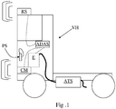
- Figure 1 discloses a vehicle VH provided with an internal combustion engine E with an ATS to treat the pollutants contained in the exhaust gas produced by the internal combustion engine.
- the vehicle further comprises the above ADAS which monitors several conditions, through relating electric signals, including pedals and levers PS, cameras CM, radars RS and the internal combustion engine E itself.
- ADAS which monitors several conditions, through relating electric signals, including pedals and levers PS, cameras CM, radars RS and the internal combustion engine E itself.
- Figure 2 discloses schematically an embodiment of an engine oil circuit including an electric pump P sucking oil from an oil sump OS. Then oil is cooled and filtered through respectively a cooler OC and filter OF.
- a valve JV is arranged on the branch of the oil circuit feeding the piston jets PJ.
- ADAS can be arranged to cause the electric pump activation and is arranged to command said valve JV to throttle such that oil pressure raises quickly for the valve actuators to rapidly prepare the engine to the forthcoming start.
- just one pump is implemented.
- the same pump is arranged to supply the entire oil circuit.
- Figure 3 discloses another preferred implementation of the present invention.
- two oil pumps are implemented: a main pump MP driven by the engine, thus a traditional pump and an electric pump P.
- the main pump can have a fixed or variable flow.
- Figure 3 discloses a dashed arrow over the pump to indicate that the oil flow is controllable.
- the main pump supplies the second oil circuit branch of the oil circuit, according to the above subdivision.
- the main pump supply the entire oil circuit with the exclusion of the oil jets PJ and possibly some further oil consumers.
- the electric pump P is arranged to normally supply the oil jets PJ and possibly said some further oil consumers, namely the first oil circuit branch.
- a 2-way valve 2V is arranged to connect the electric pump selectively with the first or the second oil circuit branch.
- the 2-way valve connects the electric pump P with the second branch and after engine cranking the 2-way valve switches in the opposite configuration connecting the electric pump P with the first branch.
- valve 2V can be maintained in normal condition, namely connecting second branch with the main pump MP and first branch with the electric pump P.
- the electric pump should be really powerful to pressurize the second branch with an increased oil viscosity.
- the internal combustion engine can be provided with a BRM Boost recuperation machine because the overall frictions are reduced.
- the oil pump is switched off just before activation engine starter to direct all the available electric energy to the starter.
- valve JV If the circuit provided of said valve JV, the latter is opened to cool piston(s).
- a BRM When a BRM is implemented, it is arranged to support energy-saving features, such as combustion engine supplementation, switching off the internal combustion engine by driving all the relevant consumers, while the vehicle coasts in zero-emission, etc.
- the BRM includes said electric motor, a DC/DC converter and a high-power battery to store energy and supply the electric motor and the electric pump P.
- the internal combustion engine thanks to the present invention can have high compression-ratio, coupled with a single medium-high voltage winding electric motor-generator defining said BRM, namely lacking a low-voltage starter or a low voltage winding.
- the latter can still be integrated to cater for extremely cold-start conditions.
- variable valve actuation VVA to vary the timing and the effective displacement of the inlet and/or exhaust cylinder valves.
- the engine volumetric efficiency is worsened well beyond the scope of the Atkinson and Miller cycles, in order to reduce the resistive torque offered by the engine during cranking operating on the inlet and/or exhaust valves.
- engine brake device suitable to open the exhaust valve at or before the top dead center to suddenly release compressed air.
- the exhaust valve is opened before top dead center in order to reduce compression of the air previously introduced in the sucking stroke.
- the aim is to minimize negative work consumed to compress air, which requires high torque from the engine starter.
- the valve actuators to realize "special" Miller/Atkinson cycles or "special” engine brake are here named as "decompressing means”.
- Said decompressing means are typically actuated through engine oil pressure.
- the VVA can be supplied in order to actuate an engine decompression to facilitate engine start.
- VVA system is not affected by a temporary oil pressure decrease, because VVA systems need oil pressure essentially during transients.
- a check valve (not shown) is arranged at the output pf the oil pump.
- This invention can be implemented advantageously in a computer program comprising program code means for performing one or more steps of such method, when such program is run on a computer.
- the patent shall also cover such computer program and the computer-readable medium that comprises a recorded message, such computer-readable medium comprising the program code means for performing one or more steps of such method, when such program is run on a computer.
Landscapes
- Engineering & Computer Science (AREA)
- Mechanical Engineering (AREA)
- General Engineering & Computer Science (AREA)
- Chemical & Material Sciences (AREA)
- Combustion & Propulsion (AREA)
- Output Control And Ontrol Of Special Type Engine (AREA)
- Lubrication Of Internal Combustion Engines (AREA)
- Control Of Vehicle Engines Or Engines For Specific Uses (AREA)
Claims (17)
- Managementverfahren zur Schmierung einer Brennkraftmaschine in einem Fahrzeug, das mit einem Stopp/Start-System versehen ist, wobei das Verfahren Folgendes umfasst:- einen Kraftmaschinenstopp und einen folgenden Kraftmaschinenstart, die durch das Stopp/Start-System bewirkt werden;- einen Schritt des automatischen Vorhersehens des anstehenden Kraftmaschinenstarts des Stopp/Start-Systems; und- infolgedessen eine Aktivierung einer elektrischen Ölpumpe vor dem Kraftmaschinenstart, derart, dass ein Schmierölkreislauf unmittelbar vor dem Auslösen des Kraftmaschinenstarts wirksam ist,wobei ein Fahrunterstützungssystem (ADAS) implementiert ist, das zumindest mit der Brennkraftmaschine in Wechselwirkung treten kann,
wobei der Schritt des automatischen Vorhersehens des anstehenden Kraftmaschinenstarts durch das Fahrunterstützungssystem (ADAS) ausgeführt wird. - Verfahren nach Anspruch 1, wobei das Auslösen des Kraftmaschinenstarts ohne Aufschub, konkret ungeachtet der Wirksamkeit des Schmierölkreislaufs, ausgeführt wird.
- Verfahren nach einem der Ansprüche 1-2, das ferner einen Schritt umfasst, der nach der Aktivierung der elektrischen Ölpumpe und vor dem Kraftmaschinenstart getätigt wird, um eine in einem Kraftmaschinenzylinder eingeschlossene Luftmasse zu verringern, um ein Gegendrehmoment zu verringern, das durch die Brennkraftmaschine aufgebracht wird, indem ein System zur Betätigung eines variablen Ventils (VVA) und/oder ein Kraftmaschinenbremssystem (EBS) eingestellt werden.
- Verfahren nach Anspruch 3, das nacheinander die folgenden Schritte umfasst:a. den Kraftmaschinenstopp und einen Stopp der elektrischen Ölpumpe;b. Vorhersehen des anstehenden Kraftmaschinenstarts durch das Fahrunterstützungssystem (ADAS);c. Aktivierung der elektrischen Ölpumpe;d. Aktivierung des Systems zur Betätigung eines variablen Ventils (VVA) und/oder des Kraftmaschinenbremssystems (EBS), um das Kraftmaschinen-Gegendrehmoment zu verringern;e. den Kraftmaschinenstart.
- Verfahren nach einem der vorhergehenden Ansprüche, das Folgendes umfasst:- automatisches Vorhersehen des anstehenden Kraftmaschinenstarts durch das Fahrunterstützungssystem (ADAS);- infolgedessen eine Aktivierung der elektrischen Ölpumpe;- darauffolgend eine Deaktivierung der elektrischen Pumpe;- den Kraftmaschinenstart,wobei die Deaktivierung der elektrischen Ölpumpe dabei unterstützt, eine verfügbare Energie einem elektrischen Anlasser zuzuweisen, der ausgelegt ist, die Brennkraftmaschine zu starten.
- Verfahren nach einem der vorhergehenden Ansprüche, wobei vor dem Kraftmaschinenstart ein erster Ölstrang der Brennkraftmaschine, der einem oder mehreren Kolben der Brennkraftmaschine Öl zuführt, gedrosselt oder ausgeschaltet wird, um einen Öldruck in Richtung eines zweiten Ölstrangs, der mit weiteren Ölverbrauchern der Brennkraftmaschine wie etwa Lagern und Ventilbetätigungsmitteln verbunden ist, zu erhöhen.
- Verfahren nach Anspruch 6, wobei eine einzige elektrische Pumpe (P) zum Zuführen von Öl sowohl zum ersten als auch zum zweiten Strang implementiert ist oder wobei eine durch die Brennkraftmaschine angetriebene Ölpumpe (MP) und eine elektrische Pumpe (P) durch ein Zweiwegeventil (2V) zusammen implementiert sind, derart, dass+ vor dem Kraftmaschinenstart das Zweiwegeventil ausgelegt ist, die elektrische Pumpe mit dem zweiten Ölstrang zu verbinden, und+ nach dem Kraftmaschinenstart das Zweiwegeventil ausgelegt ist, die durch die Kraftmaschine angetriebene Ölpumpe (MP) mit dem zweiten Ölstrang und die elektrische Pumpe mit dem ersten Ölstrang zu verbinden.
- Verfahren nach einem der vorhergehenden Ansprüche, wobei das Fahrunterstützungssystem (ADAS) ausgelegt ist, die Aktivierung der elektrischen Ölpumpe zu bewirken.
- Verfahren nach Anspruch 1, wobei der anstehende Kraftmaschinenstart durch das Fahrunterstützungssystem (ADAS) vorhergesehen wird, wenn die Kraftmaschine stillsteht, und- eine Betriebsbremse gelöst wird, und/oder- ein grünes Licht einer Lichtzeichenanlage erscheint.
- Verfahren nach Anspruch 1, wobei der anstehende Kraftmaschinenstart durch das Fahrunterstützungssystem (ADAS) vorhergesehen wird, wenn die Kraftmaschine vor dem Kraftmaschinenstopp in Betrieb gewesen ist und ein Stopp-Verkehrsschild oder ein gelbes oder rotes Licht einer Lichtzeichenanlage erscheint.
- Fahrzeug, das mit einer Brennkraftmaschine (E) und mit einem Stopp/Start-System (S&S-System), das Stopp und Start der Brennkraftmaschine managen kann, versehen ist, wobei die Brennkraftmaschine mit einer elektrischen Ölpumpe und mit Steuermitteln, die ein Fahrunterstützungssystem (ADAS) umfassen, das konfiguriert ist, einen anstehenden Kraftmaschinenstart des Stopp/Start-Systems (S&S) vorherzusehen, und wobei die Steuermittel konfiguriert sind, infolgedessen die elektrische Ölpumpe vor dem Kraftmaschinenstart zu aktivieren, versehen ist.
- Fahrzeug nach Anspruch 11, wobei die Brennkraftmaschine ferner mit einem Dekompressionsmittel ausgerüstet ist und wobei die Steuermittel konfiguriert sind, automatisch ein Kraftmaschinen-Gegendrehmoment vorübergehend zu verringern, um die Drehung der Kraftmaschine zu erleichtern, wenn ein anstehender Kraftmaschinenstart detektiert oder vorhergesehen wird.
- Fahrzeug nach Anspruch 11, wobei das Fahrunterstützungssystem (ADAS) ausgelegt ist, die Aktivierung der elektrischen Ölpumpe zu bewirken.
- Fahrzeug nach Anspruch 11, wobei die Steuermittel eine Steuereinheit umfassen, die programmiert ist, das Verfahren nach einem der Ansprüche 1 bis 10 auszuführen.
- Fahrzeug nach einem der vorhergehenden Ansprüche von 11 bis 14, das mit einer Ladedruck-Rückgewinnungsmaschine (BRM) versehen ist, die ausgelegt ist, die Kraftmaschine ohne einen Niederspannungsanlasser zu starten.
- Computerprogramm, das Computerprogrammcodemittel umfasst, die ausgelegt sind, das Verfahren nach einem der Ansprüche von 1 bis 10 durchzuführen, wenn das Programm auf einer Steuereinheit abläuft.
- Computerlesbares Medium, auf dem ein Programm aufgezeichnet ist, wobei das computerlesbare Medium Computerprogrammcodemittel umfasst, die ausgelegt sind, das Verfahren nach einem der Ansprüche von 1 bis 10 durchzuführen, wenn das Programm auf einer Steuereinheit abläuft.
Applications Claiming Priority (1)
| Application Number | Priority Date | Filing Date | Title |
|---|---|---|---|
| IT102018000003414A IT201800003414A1 (it) | 2018-03-09 | 2018-03-09 | Metodo di gestione di una lubrificazione di un motore a combustione interna e motore a combustione interna che implementa il metodo |
Publications (2)
| Publication Number | Publication Date |
|---|---|
| EP3536918A1 EP3536918A1 (de) | 2019-09-11 |
| EP3536918B1 true EP3536918B1 (de) | 2021-12-29 |
Family
ID=62143529
Family Applications (1)
| Application Number | Title | Priority Date | Filing Date |
|---|---|---|---|
| EP19161749.7A Active EP3536918B1 (de) | 2018-03-09 | 2019-03-08 | Verfahren zur steuerung einer schmierung eines verbrennungsmotors und verbrennungsmotor mit implementierung des verfahrens |
Country Status (3)
| Country | Link |
|---|---|
| EP (1) | EP3536918B1 (de) |
| ES (1) | ES2908635T3 (de) |
| IT (1) | IT201800003414A1 (de) |
Families Citing this family (3)
| Publication number | Priority date | Publication date | Assignee | Title |
|---|---|---|---|---|
| GB2591272A (en) * | 2020-01-23 | 2021-07-28 | Daimler Ag | Internal combustion engine for a vehicle |
| GB2595874A (en) * | 2020-06-09 | 2021-12-15 | Daimler Ag | A method for operating a lubricating and piston cooling system for an engine of a vehicle and a lubricating and piston cooling system |
| CN112727562A (zh) * | 2021-02-08 | 2021-04-30 | 陈海豹 | 一种发动机的预润滑装置 |
Family Cites Families (9)
| Publication number | Priority date | Publication date | Assignee | Title |
|---|---|---|---|---|
| DE3929078A1 (de) * | 1989-09-01 | 1991-03-07 | Blaj Adrian Dipl Ing | Verfahren zur schmierung von brennkraftmaschinen und vorrichtung zur durchfuehrung dieses verfahrens |
| US6029621A (en) * | 1998-05-28 | 2000-02-29 | Lear Automotive Dearborn, Inc. | Remotely controlled engine prelubrication system |
| DE10035049A1 (de) * | 2000-07-19 | 2002-01-31 | Daimler Chrysler Ag | Verfahren und Vorrichtung zum Start-Stopp-Betrieb eines Kraftfahrzeuges |
| US6637394B2 (en) * | 2001-08-31 | 2003-10-28 | International Truck Intellectual Property Company, Llc. | System and method for vehicle engine cranking |
| JP2006144567A (ja) * | 2004-11-16 | 2006-06-08 | Toyota Motor Corp | 内燃機関のバルブタイミング制御装置 |
| US20100288570A1 (en) * | 2009-05-18 | 2010-11-18 | Gm Global Technology Operations, Inc. | Tandem dual pumps for a hybrid propulsion system |
| FR3002974B1 (fr) * | 2013-03-05 | 2015-04-03 | Peugeot Citroen Automobiles Sa | Dispositif de demarrage de moteur thermique de vehicule automobile a mise en pression d'huile de lubrification |
| ITUB20153993A1 (it) * | 2015-09-29 | 2017-03-29 | Fpt Motorenforschung Ag | Circuito a olio di lubrificazione e raffreddamento di un motore a combustione interna |
| DE102015223588B4 (de) * | 2015-11-27 | 2025-10-23 | Bayerische Motoren Werke Aktiengesellschaft | Steuersystem mit mindestens einer elektronischen Steuereinheit zur Steuerung eines Verbrennungsmotors in einem Hybridfahrzeug |
-
2018
- 2018-03-09 IT IT102018000003414A patent/IT201800003414A1/it unknown
-
2019
- 2019-03-08 ES ES19161749T patent/ES2908635T3/es active Active
- 2019-03-08 EP EP19161749.7A patent/EP3536918B1/de active Active
Also Published As
| Publication number | Publication date |
|---|---|
| ES2908635T3 (es) | 2022-05-03 |
| EP3536918A1 (de) | 2019-09-11 |
| IT201800003414A1 (it) | 2019-09-09 |
Similar Documents
| Publication | Publication Date | Title |
|---|---|---|
| US9322343B2 (en) | Method for automatically switching off and starting an internal combustion engine of a motor vehicle with an automatic transmission, during or after an overrun phase | |
| EP3536918B1 (de) | Verfahren zur steuerung einer schmierung eines verbrennungsmotors und verbrennungsmotor mit implementierung des verfahrens | |
| RU2717608C2 (ru) | Способ и система для замедления транспортного средства | |
| CN102030001B (zh) | 自动再起动车辆发动机的系统和方法 | |
| US9926901B2 (en) | Hydraulic starter and pre-lubrication system for an internal combustion engine | |
| JP2002339841A (ja) | 車両の油圧式エンジン始動装置 | |
| CN104648373A (zh) | 用于停止/起动发动机的方法和系统 | |
| JP4930266B2 (ja) | 内燃機関の油圧制御装置 | |
| US6672267B2 (en) | Engine-starting apparatus having overrunning clutch | |
| CN105934378B (zh) | 车辆的控制装置 | |
| US11725550B2 (en) | Control method, controller, and control program for controlling lubricating system, computer-readable medium carrying control program, lubricating system, and vehicle | |
| US20070221149A1 (en) | Auxiliary cam phaser hydraulic circuit and method of operation | |
| JP5255618B2 (ja) | 内燃機関の始動方法 | |
| EP3088710B1 (de) | Steuerung und steuerungsverfahren für motoren | |
| JP2002295219A (ja) | 機関の潤滑装置 | |
| JP5887727B2 (ja) | 内燃機関及びその制御方法 | |
| US20130129475A1 (en) | Method for operating a pump | |
| WO2020052735A1 (en) | A vehicle system, and a method for operating an internal combustion engine | |
| IT201800003411A1 (it) | Sistema di gestione dell'avviamento di un motore a combustione interna | |
| US20200158068A1 (en) | Start control device and start control method for engine | |
| EP3434886A1 (de) | Regelungsverfahren für ein abgasnachbehandlungssystem | |
| US12228102B2 (en) | Control method, controller, and control program for controlling starting system, computer-readable medium carrying control program, starting system, and vehicle | |
| WO2018013040A1 (en) | Method and system for starting an internal combustion engine | |
| CN118613645A (zh) | 包括发动机高速启动能力的设备、方法和系统 | |
| US9371785B2 (en) | Vehicle and method of operating |
Legal Events
| Date | Code | Title | Description |
|---|---|---|---|
| PUAI | Public reference made under article 153(3) epc to a published international application that has entered the european phase |
Free format text: ORIGINAL CODE: 0009012 |
|
| STAA | Information on the status of an ep patent application or granted ep patent |
Free format text: STATUS: THE APPLICATION HAS BEEN PUBLISHED |
|
| AK | Designated contracting states |
Kind code of ref document: A1 Designated state(s): AL AT BE BG CH CY CZ DE DK EE ES FI FR GB GR HR HU IE IS IT LI LT LU LV MC MK MT NL NO PL PT RO RS SE SI SK SM TR |
|
| AX | Request for extension of the european patent |
Extension state: BA ME |
|
| STAA | Information on the status of an ep patent application or granted ep patent |
Free format text: STATUS: REQUEST FOR EXAMINATION WAS MADE |
|
| 17P | Request for examination filed |
Effective date: 20200213 |
|
| RBV | Designated contracting states (corrected) |
Designated state(s): AL AT BE BG CH CY CZ DE DK EE ES FI FR GB GR HR HU IE IS IT LI LT LU LV MC MK MT NL NO PL PT RO RS SE SI SK SM TR |
|
| GRAP | Despatch of communication of intention to grant a patent |
Free format text: ORIGINAL CODE: EPIDOSNIGR1 |
|
| STAA | Information on the status of an ep patent application or granted ep patent |
Free format text: STATUS: GRANT OF PATENT IS INTENDED |
|
| RIC1 | Information provided on ipc code assigned before grant |
Ipc: F01M 5/02 20060101AFI20210629BHEP Ipc: F02N 11/08 20060101ALI20210629BHEP Ipc: F02N 19/00 20100101ALI20210629BHEP Ipc: F01M 1/02 20060101ALN20210629BHEP Ipc: F01M 5/00 20060101ALN20210629BHEP Ipc: F02D 41/00 20060101ALN20210629BHEP Ipc: F16N 13/06 20060101ALN20210629BHEP Ipc: F01M 1/12 20060101ALN20210629BHEP |
|
| INTG | Intention to grant announced |
Effective date: 20210721 |
|
| GRAS | Grant fee paid |
Free format text: ORIGINAL CODE: EPIDOSNIGR3 |
|
| GRAA | (expected) grant |
Free format text: ORIGINAL CODE: 0009210 |
|
| STAA | Information on the status of an ep patent application or granted ep patent |
Free format text: STATUS: THE PATENT HAS BEEN GRANTED |
|
| AK | Designated contracting states |
Kind code of ref document: B1 Designated state(s): AL AT BE BG CH CY CZ DE DK EE ES FI FR GB GR HR HU IE IS IT LI LT LU LV MC MK MT NL NO PL PT RO RS SE SI SK SM TR |
|
| REG | Reference to a national code |
Ref country code: GB Ref legal event code: FG4D |
|
| REG | Reference to a national code |
Ref country code: CH Ref legal event code: EP |
|
| REG | Reference to a national code |
Ref country code: AT Ref legal event code: REF Ref document number: 1458835 Country of ref document: AT Kind code of ref document: T Effective date: 20220115 |
|
| REG | Reference to a national code |
Ref country code: IE Ref legal event code: FG4D |
|
| REG | Reference to a national code |
Ref country code: DE Ref legal event code: R096 Ref document number: 602019010353 Country of ref document: DE |
|
| REG | Reference to a national code |
Ref country code: LT Ref legal event code: MG9D |
|
| PG25 | Lapsed in a contracting state [announced via postgrant information from national office to epo] |
Ref country code: RS Free format text: LAPSE BECAUSE OF FAILURE TO SUBMIT A TRANSLATION OF THE DESCRIPTION OR TO PAY THE FEE WITHIN THE PRESCRIBED TIME-LIMIT Effective date: 20211229 Ref country code: LT Free format text: LAPSE BECAUSE OF FAILURE TO SUBMIT A TRANSLATION OF THE DESCRIPTION OR TO PAY THE FEE WITHIN THE PRESCRIBED TIME-LIMIT Effective date: 20211229 Ref country code: FI Free format text: LAPSE BECAUSE OF FAILURE TO SUBMIT A TRANSLATION OF THE DESCRIPTION OR TO PAY THE FEE WITHIN THE PRESCRIBED TIME-LIMIT Effective date: 20211229 Ref country code: BG Free format text: LAPSE BECAUSE OF FAILURE TO SUBMIT A TRANSLATION OF THE DESCRIPTION OR TO PAY THE FEE WITHIN THE PRESCRIBED TIME-LIMIT Effective date: 20220329 |
|
| REG | Reference to a national code |
Ref country code: ES Ref legal event code: FG2A Ref document number: 2908635 Country of ref document: ES Kind code of ref document: T3 Effective date: 20220503 |
|
| REG | Reference to a national code |
Ref country code: NL Ref legal event code: MP Effective date: 20211229 |
|
| REG | Reference to a national code |
Ref country code: AT Ref legal event code: MK05 Ref document number: 1458835 Country of ref document: AT Kind code of ref document: T Effective date: 20211229 |
|
| PG25 | Lapsed in a contracting state [announced via postgrant information from national office to epo] |
Ref country code: SE Free format text: LAPSE BECAUSE OF FAILURE TO SUBMIT A TRANSLATION OF THE DESCRIPTION OR TO PAY THE FEE WITHIN THE PRESCRIBED TIME-LIMIT Effective date: 20211229 Ref country code: NO Free format text: LAPSE BECAUSE OF FAILURE TO SUBMIT A TRANSLATION OF THE DESCRIPTION OR TO PAY THE FEE WITHIN THE PRESCRIBED TIME-LIMIT Effective date: 20220329 Ref country code: LV Free format text: LAPSE BECAUSE OF FAILURE TO SUBMIT A TRANSLATION OF THE DESCRIPTION OR TO PAY THE FEE WITHIN THE PRESCRIBED TIME-LIMIT Effective date: 20211229 Ref country code: HR Free format text: LAPSE BECAUSE OF FAILURE TO SUBMIT A TRANSLATION OF THE DESCRIPTION OR TO PAY THE FEE WITHIN THE PRESCRIBED TIME-LIMIT Effective date: 20211229 Ref country code: GR Free format text: LAPSE BECAUSE OF FAILURE TO SUBMIT A TRANSLATION OF THE DESCRIPTION OR TO PAY THE FEE WITHIN THE PRESCRIBED TIME-LIMIT Effective date: 20220330 |
|
| PG25 | Lapsed in a contracting state [announced via postgrant information from national office to epo] |
Ref country code: NL Free format text: LAPSE BECAUSE OF FAILURE TO SUBMIT A TRANSLATION OF THE DESCRIPTION OR TO PAY THE FEE WITHIN THE PRESCRIBED TIME-LIMIT Effective date: 20211229 |
|
| PG25 | Lapsed in a contracting state [announced via postgrant information from national office to epo] |
Ref country code: SM Free format text: LAPSE BECAUSE OF FAILURE TO SUBMIT A TRANSLATION OF THE DESCRIPTION OR TO PAY THE FEE WITHIN THE PRESCRIBED TIME-LIMIT Effective date: 20211229 Ref country code: SK Free format text: LAPSE BECAUSE OF FAILURE TO SUBMIT A TRANSLATION OF THE DESCRIPTION OR TO PAY THE FEE WITHIN THE PRESCRIBED TIME-LIMIT Effective date: 20211229 Ref country code: RO Free format text: LAPSE BECAUSE OF FAILURE TO SUBMIT A TRANSLATION OF THE DESCRIPTION OR TO PAY THE FEE WITHIN THE PRESCRIBED TIME-LIMIT Effective date: 20211229 Ref country code: PT Free format text: LAPSE BECAUSE OF FAILURE TO SUBMIT A TRANSLATION OF THE DESCRIPTION OR TO PAY THE FEE WITHIN THE PRESCRIBED TIME-LIMIT Effective date: 20220429 Ref country code: EE Free format text: LAPSE BECAUSE OF FAILURE TO SUBMIT A TRANSLATION OF THE DESCRIPTION OR TO PAY THE FEE WITHIN THE PRESCRIBED TIME-LIMIT Effective date: 20211229 Ref country code: CZ Free format text: LAPSE BECAUSE OF FAILURE TO SUBMIT A TRANSLATION OF THE DESCRIPTION OR TO PAY THE FEE WITHIN THE PRESCRIBED TIME-LIMIT Effective date: 20211229 |
|
| PG25 | Lapsed in a contracting state [announced via postgrant information from national office to epo] |
Ref country code: PL Free format text: LAPSE BECAUSE OF FAILURE TO SUBMIT A TRANSLATION OF THE DESCRIPTION OR TO PAY THE FEE WITHIN THE PRESCRIBED TIME-LIMIT Effective date: 20211229 Ref country code: AT Free format text: LAPSE BECAUSE OF FAILURE TO SUBMIT A TRANSLATION OF THE DESCRIPTION OR TO PAY THE FEE WITHIN THE PRESCRIBED TIME-LIMIT Effective date: 20211229 |
|
| PG25 | Lapsed in a contracting state [announced via postgrant information from national office to epo] |
Ref country code: IS Free format text: LAPSE BECAUSE OF FAILURE TO SUBMIT A TRANSLATION OF THE DESCRIPTION OR TO PAY THE FEE WITHIN THE PRESCRIBED TIME-LIMIT Effective date: 20220429 |
|
| REG | Reference to a national code |
Ref country code: DE Ref legal event code: R097 Ref document number: 602019010353 Country of ref document: DE |
|
| PG25 | Lapsed in a contracting state [announced via postgrant information from national office to epo] |
Ref country code: MC Free format text: LAPSE BECAUSE OF FAILURE TO SUBMIT A TRANSLATION OF THE DESCRIPTION OR TO PAY THE FEE WITHIN THE PRESCRIBED TIME-LIMIT Effective date: 20211229 Ref country code: DK Free format text: LAPSE BECAUSE OF FAILURE TO SUBMIT A TRANSLATION OF THE DESCRIPTION OR TO PAY THE FEE WITHIN THE PRESCRIBED TIME-LIMIT Effective date: 20211229 Ref country code: AL Free format text: LAPSE BECAUSE OF FAILURE TO SUBMIT A TRANSLATION OF THE DESCRIPTION OR TO PAY THE FEE WITHIN THE PRESCRIBED TIME-LIMIT Effective date: 20211229 |
|
| REG | Reference to a national code |
Ref country code: CH Ref legal event code: PL |
|
| PLBE | No opposition filed within time limit |
Free format text: ORIGINAL CODE: 0009261 |
|
| STAA | Information on the status of an ep patent application or granted ep patent |
Free format text: STATUS: NO OPPOSITION FILED WITHIN TIME LIMIT |
|
| 26N | No opposition filed |
Effective date: 20220930 |
|
| REG | Reference to a national code |
Ref country code: BE Ref legal event code: MM Effective date: 20220331 |
|
| PG25 | Lapsed in a contracting state [announced via postgrant information from national office to epo] |
Ref country code: LU Free format text: LAPSE BECAUSE OF NON-PAYMENT OF DUE FEES Effective date: 20220308 Ref country code: LI Free format text: LAPSE BECAUSE OF NON-PAYMENT OF DUE FEES Effective date: 20220331 Ref country code: IE Free format text: LAPSE BECAUSE OF NON-PAYMENT OF DUE FEES Effective date: 20220308 Ref country code: CH Free format text: LAPSE BECAUSE OF NON-PAYMENT OF DUE FEES Effective date: 20220331 |
|
| PG25 | Lapsed in a contracting state [announced via postgrant information from national office to epo] |
Ref country code: SI Free format text: LAPSE BECAUSE OF FAILURE TO SUBMIT A TRANSLATION OF THE DESCRIPTION OR TO PAY THE FEE WITHIN THE PRESCRIBED TIME-LIMIT Effective date: 20211229 Ref country code: BE Free format text: LAPSE BECAUSE OF NON-PAYMENT OF DUE FEES Effective date: 20220331 |
|
| P01 | Opt-out of the competence of the unified patent court (upc) registered |
Effective date: 20230519 |
|
| PG25 | Lapsed in a contracting state [announced via postgrant information from national office to epo] |
Ref country code: MK Free format text: LAPSE BECAUSE OF FAILURE TO SUBMIT A TRANSLATION OF THE DESCRIPTION OR TO PAY THE FEE WITHIN THE PRESCRIBED TIME-LIMIT Effective date: 20211229 Ref country code: CY Free format text: LAPSE BECAUSE OF FAILURE TO SUBMIT A TRANSLATION OF THE DESCRIPTION OR TO PAY THE FEE WITHIN THE PRESCRIBED TIME-LIMIT Effective date: 20211229 |
|
| PG25 | Lapsed in a contracting state [announced via postgrant information from national office to epo] |
Ref country code: HU Free format text: LAPSE BECAUSE OF FAILURE TO SUBMIT A TRANSLATION OF THE DESCRIPTION OR TO PAY THE FEE WITHIN THE PRESCRIBED TIME-LIMIT; INVALID AB INITIO Effective date: 20190308 |
|
| PG25 | Lapsed in a contracting state [announced via postgrant information from national office to epo] |
Ref country code: TR Free format text: LAPSE BECAUSE OF FAILURE TO SUBMIT A TRANSLATION OF THE DESCRIPTION OR TO PAY THE FEE WITHIN THE PRESCRIBED TIME-LIMIT Effective date: 20211229 |
|
| PG25 | Lapsed in a contracting state [announced via postgrant information from national office to epo] |
Ref country code: MT Free format text: LAPSE BECAUSE OF FAILURE TO SUBMIT A TRANSLATION OF THE DESCRIPTION OR TO PAY THE FEE WITHIN THE PRESCRIBED TIME-LIMIT Effective date: 20211229 |
|
| PGFP | Annual fee paid to national office [announced via postgrant information from national office to epo] |
Ref country code: ES Payment date: 20250423 Year of fee payment: 7 |
|
| PGFP | Annual fee paid to national office [announced via postgrant information from national office to epo] |
Ref country code: GB Payment date: 20260122 Year of fee payment: 8 |
|
| PGFP | Annual fee paid to national office [announced via postgrant information from national office to epo] |
Ref country code: DE Payment date: 20260320 Year of fee payment: 8 |
|
| PGFP | Annual fee paid to national office [announced via postgrant information from national office to epo] |
Ref country code: IT Payment date: 20260311 Year of fee payment: 8 |
|
| PGFP | Annual fee paid to national office [announced via postgrant information from national office to epo] |
Ref country code: FR Payment date: 20260323 Year of fee payment: 8 |