EP3536893B1 - Connection for percussion drilling - Google Patents
Connection for percussion drilling Download PDFInfo
- Publication number
- EP3536893B1 EP3536893B1 EP18160853.0A EP18160853A EP3536893B1 EP 3536893 B1 EP3536893 B1 EP 3536893B1 EP 18160853 A EP18160853 A EP 18160853A EP 3536893 B1 EP3536893 B1 EP 3536893B1
- Authority
- EP
- European Patent Office
- Prior art keywords
- thread
- contact flank
- crest
- male
- female
- Prior art date
- Legal status (The legal status is an assumption and is not a legal conclusion. Google has not performed a legal analysis and makes no representation as to the accuracy of the status listed.)
- Active
Links
- 238000009527 percussion Methods 0.000 title claims description 20
- 238000005553 drilling Methods 0.000 title claims description 13
- 230000008878 coupling Effects 0.000 claims description 82
- 238000010168 coupling process Methods 0.000 claims description 82
- 238000005859 coupling reaction Methods 0.000 claims description 82
- 239000011435 rock Substances 0.000 description 4
- 239000002184 metal Substances 0.000 description 3
- 230000000295 complement effect Effects 0.000 description 2
- 229910000831 Steel Inorganic materials 0.000 description 1
- 230000002159 abnormal effect Effects 0.000 description 1
- 239000000956 alloy Substances 0.000 description 1
- 229910045601 alloy Inorganic materials 0.000 description 1
- 238000005219 brazing Methods 0.000 description 1
- 239000011195 cermet Substances 0.000 description 1
- 230000009977 dual effect Effects 0.000 description 1
- 239000012530 fluid Substances 0.000 description 1
- 239000000463 material Substances 0.000 description 1
- 239000010959 steel Substances 0.000 description 1
Images


Classifications
-
- E—FIXED CONSTRUCTIONS
- E21—EARTH DRILLING; MINING
- E21B—EARTH DRILLING, e.g. DEEP DRILLING; OBTAINING OIL, GAS, WATER, SOLUBLE OR MELTABLE MATERIALS OR A SLURRY OF MINERALS FROM WELLS
- E21B17/00—Drilling rods or pipes; Flexible drill strings; Kellies; Drill collars; Sucker rods; Cables; Casings; Tubings
- E21B17/02—Couplings; joints
- E21B17/04—Couplings; joints between rod or the like and bit or between rod and rod or the like
- E21B17/042—Threaded
- E21B17/0426—Threaded with a threaded cylindrical portion, e.g. for percussion rods
-
- E—FIXED CONSTRUCTIONS
- E21—EARTH DRILLING; MINING
- E21B—EARTH DRILLING, e.g. DEEP DRILLING; OBTAINING OIL, GAS, WATER, SOLUBLE OR MELTABLE MATERIALS OR A SLURRY OF MINERALS FROM WELLS
- E21B1/00—Percussion drilling
-
- F—MECHANICAL ENGINEERING; LIGHTING; HEATING; WEAPONS; BLASTING
- F16—ENGINEERING ELEMENTS AND UNITS; GENERAL MEASURES FOR PRODUCING AND MAINTAINING EFFECTIVE FUNCTIONING OF MACHINES OR INSTALLATIONS; THERMAL INSULATION IN GENERAL
- F16L—PIPES; JOINTS OR FITTINGS FOR PIPES; SUPPORTS FOR PIPES, CABLES OR PROTECTIVE TUBING; MEANS FOR THERMAL INSULATION IN GENERAL
- F16L15/00—Screw-threaded joints; Forms of screw-threads for such joints
- F16L15/06—Screw-threaded joints; Forms of screw-threads for such joints characterised by the shape of the screw-thread
Definitions
- the present disclosure generally relates to a wear resistant connection for use in percussion drilling.
- the exploration drill rod thread structure includes external threads and internal threads, wherein the external threads are composed of external thread units, the internal threads are composed of internal thread units, the external thread units are composed of first roots and external thread teeth, the internal thread units are composed of second roots and internal thread teeth, the shapes of the external thread teeth and the internal thread teeth mutually correspond, and the external thread teeth and the internal thread teeth are in an abnormal asymmetric structure.
- EP 0 009 398 / US 4,295,751 discloses a coupling thread structure for percussion drill elements including a rod having an external thread, and a sleeve having an internal thread with the threads, when the sleeve and rod are coupled, having abutting and non-abutting flanks and with the flanks being joined by bottom and crest portions, wherein the threads have at least two starts;
- the abutting flanks are substantially straight along their whole abutting contact portions and form an angle of between 10° and 25°, preferably 15° to 20°, with the drill axis;
- the pitch angle of the threads is in the range 9° to 20°, preferably 11° to 16°;
- the crest portions are substantially straight and intersect the abutting flank portions at a well-defined edge;
- the non-abutting flanks have a flank angle which is considerably greater than that of the abutting flanks;
- the flank angle of the non-abutting flanks is in the range
- EP 0 253 789 / US 4,861,209 discloses a threaded coupling for a high frequency percussion drill assembly including a rod and a sleeve having external and internal threads, respectively.
- the threads are of the asymmetrical type and make contact along opposing shoulder portions disposed on only one side of each crown portion.
- the threads have a maximum diameter from 30 to 40 mm, a pitch of 7 to 11 mm, and a height from 1.2 to 1.6 mm.
- the parts of the root and crown portions located immediate adjacent the contacting shoulder portions have radii from 3 to 5 mm.
- EP 0 324 442 / US 4,799,844 discloses a screw structure provided for male and female threads having at least one thread extending helically along a cylindrical support member in spaced thread turns. A root portion extends between adjacent thread turns and has a curvature defined by a portion of an ellipse for providing improved stress reduction during periods of severe loading.
- EP 2 710 217 / US 2014/0083778 discloses a device in a drill string component for percussive rock drilling including a thread for threading together with another drill string component including a complementary thread.
- the thread includes a thread groove formed by two thread flanks and an intermediate thread bottom. In operation one of the flanks forms a pressure flank.
- the thread groove has an essentially equally shaped sectional form along its axial extension.
- the thread bottom exhibits at least three surface portions with part-circular shape, as seen in an axial section.
- the surface portions with part-circular shape have increasing radiuses, as seen from each thread flank to an intermediate surface portion of the thread bottom.
- a thread joint and a drill string component are also known in a drill string component.
- US 4,040,756 discloses a thread structure for use in coupling percussion drilling extension rods minimizes the torque necessary to disconnect such extension rods. This is accomplished by beveling the crest portions of the cooperating thread structures. The direction of the bevel is such that the greatest intrusion of the crest portions into the complementary portions of the cooperating thread structure occurs immediately adjacent the abutting flanks thereof. The abutting flanks then wear in such a way that wedging is substantially avoided. Additionally, the root portions are defined by a continuously curved surface that smoothly extends into a flat surface defining the thread flanks so that fatigue stresses are minimized.
- the prior art generally fails to take into consideration the performance of the threads as they become worn. Accordingly, it is desirable to provide an improved drill string thread for percussion rock drilling that does not suffer from the shortcomings of the prior art.
- a connection for percussion drilling includes a male coupling and a female coupling.
- Each coupling includes a body and a respective screw thread formed on a respective inner or outer surface of the respective body.
- Each thread has a thread-form including a crest, a root, a contact flank and a non-contact flank.
- Each thread-form has a contact flank angle and a non-contact flank angle inclined relative to a respective baseline located at a respective minor or major diameter thereof.
- Each non-contact flank angle is greater than the respective contact flank angle.
- the crest of each thread-form is inclined from the respective contact flank to the respective non-contact flank such that an apex of the respective thread-form defining a respective major or minor diameter thereof is located adjacent to the respective non-contact flank.
- the contact flanks become enlarged in response to wear of the couplings. Further, pitting formed in regions adjacent to the contact flanks may be removed as a result of the wear.
- the CN'913 application does not identify the contact flanks and the non-contact flanks.
- the EP '398 patent discloses a main embodiment where the threads have straight crests and an alternative where the crests are declined.
- the EP '789 patent discloses threads with semi-circular crests.
- the EP '442 patent discloses threads with straight crests.
- the EP '217 patent discloses threads with straight crests.
- the US '756 patent discloses threads with declined crests and teaches away from inclined crests by emphasizing the need for the declined crests to avoid wedging of the threads in the worn condition.
- each contact flank angle ranges between 15 and 50 degrees and each non-contact flank angle equals the respective contact flank angle plus 5 to 30 degrees.
- the inclination of each crest is arcuate with a radius greater than 10 percent of an outer diameter of the male coupling. In another aspect of the embodiment, the inclination of each crest is linear.
- a height of each crest adjacent to the respective non-contact flank is 5 to 20 percent greater than a height of the respective crest adjacent to the respective contact flank.
- each root is a first arc
- each contact flank is connected to the respective root by a respective second arc.
- a first radius of each first arc is greater than a second radius of the respective second arc.
- each first radius is at least 50 percent greater than the respective second radius, and each second radius is greater than five percent of an outer diameter of the male coupling.
- an area of the male thread-from is at least two percent greater than an area of the female thread-form.
- each non-contact flank is connected to the respective crest by a respective arc.
- an outer diameter of the couplings ranges between two and 16 centimeters.
- each diameter is constant.
- a drill rod for percussion drilling includes: a rod body; the female coupling integrally formed with or welded to a first end of the rod body; and the male coupling integrally formed with or welded to a second end of the rod body.
- a drill string comprising a drill rod.
- a drill rod for percussion drilling includes: a rod body; the female coupling integrally formed in a first end of the rod body; and the male coupling integrally formed in a second end of the rod body.
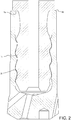
- Figure 1 illustrates a male coupling 1 and a female coupling 2 for a percussion drill string, each coupling including a wear resistant screw thread 1t, 2t, according to one embodiment of the present disclosure.
- the percussion drill string may be formed by screwing together a plurality of drill rods ( Figure 4 ) together along with a percussion drill bit 3 at one end and a shank adapter (not shown) at the other end.
- the drill rods may be screwed together using the male 1 and female couplings 2.
- the drill string may be used for percussion rock drilling with a top hammer (not shown) or downhole hammer (not shown). If a downhole hammer is used, the hammer may have each of the wear resistant screw threads 1t, 2t for assembly as part of the drill string.
- the male coupling 1 may be attached, such as welded, to an intermediate rod body so as to form a longitudinal end of a drill rod.
- the female coupling 2 may be formed integrally with the percussion drill bit 3.
- the male coupling 1 may have a tubular body with an outer diameter upper portion for connection to a lower end of the rod body, a reduced diameter lower portion having the external male thread 1t formed in an outer surface thereof, and a shoulder 1s connecting the upper and lower portions.
- the male thread 1t may start at a first standoff distance from the shoulder 1s.
- the male thread 1t may end at a second standoff distance from a bottom thereof.
- a guide portion such as a conical surface, may be formed in the outer surface of the lower portion of the male coupling 1 between the end of the male thread 1t and the bottom thereof.
- the upper portion of the male coupling 1 may have a plurality of wrench flats (not shown) formed in an outer surface thereof.
- the male coupling 1 may have a flow bore formed therethrough.
- An outer diameter of the couplings 1, 2 may range between two and 16 centimeters.
- the female coupling 2 may serve as the shank of the percussion drill bit 3.
- the percussion drill bit 3 may further include a head.
- the head may have an outermost end defining a cutting face.
- the cutting face may have a plurality of sockets (only one shown) formed therein for receiving crushers (not shown).
- Each crusher may be a pre-formed insert mounted into the respective socket by interference fit or brazing.
- Each cutter may be made from a cermet material, such as a cemented carbide.
- the sockets and cutters may be spaced about the cutting face.
- FIG. 2 illustrates the male 1 and female 2 couplings screwed together.
- the female coupling 2 may have a tubular body.
- the female coupling 2 may have the internal female thread 2t formed in an inner surface thereof adjacent to the flow bore thereof.
- the flow bore may be sized to receive the reduced diameter lower portion of the male coupling 1.
- the male coupling 1 may be screwed into the female coupling 2 until the shoulder 1s abuts a top 2p of the female coupling, thereby creating a metal-to-metal seal for isolating the flow bore and fastening the two members together.
- the female thread 2t may start at a first standoff distance from the top 2p.
- the female thread 2t may end at a second standoff distance from a bottom of the female coupling 2.
- the flow bore of the female coupling 2 may be in fluid communication with flow ports formed through the head of the drill bit.
- Each of the male 1t and female 2t threads may be single threads.
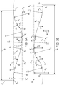
- FIG 3A illustrates a thread-form 4f of the female thread 2t.
- Figure 3B illustrates a thread-form 4m of the male thread 1t.
- Each thread-form 4m,f may start at point X B and may include a root A 1 .
- Each root A 1 may be a concave arc with a respective radius R 1 and may extend to a respective second arc A 2 .
- Each second arc A 2 may be concave, have a respective radius R 2 , and may extend from the respective first crest A 1 to a respective contact flank E 1 .
- Each root radius R 1 may be greater than the respective second radius R 2 , such as at least fifty percent greater than the respective second radius.
- Each second radius R 2 may be greater than five percent of the outer diameter of the male coupling 1.
- Each contact flank E 1 may be a straight line inclined at a respective first flank angle ⁇ relative to a respective baseline BL.
- the baseline BL may be longitudinal and be located at a respective major diameter D J or minor diameter D N of the respective thread 1t, 2t.
- Each first flank angle ⁇ may range between 15 and 50 degrees.
- Each contact flank E 1 may extend from the respective second arc A 2 to a respective third arc A 3 .
- Each third arc A 3 may be convex and have a respective radius R 3 .
- Each third arc A 3 may extend from the respective contact flank E 1 to a respective crest A 4 .
- Each crest A 4 may have a respective first height H 1 adjacent to the respective third arc A 3 and a respective second height H 2 adjacent to a respective fifth arc A 5 .
- Each height H 1 ,H 2 may be measured from the respective baseline BL.
- Each crest A 4 may be inclined from the respective contact flank E 1 to the respective non-contact flank E 2 such that a respective apex X A of the respective thread-form 4m, 4f defining the respective major diameter D J or minor diameter D N is located adjacent to the respective non-contact flank.
- Each thread-form 4m, 4f may have a respective peak line PL which may be longitudinal and be located at the respective major diameter D J or minor diameter D N of the respective thread 1t, 2t. Each diameter D N , D J of the respective thread 1t, 2t may be constant. Due to the inclination of each crest A 4 , the respective second height H 2 may be greater than the respective first height H 1 . Each inclination may be accomplished by the respective crest A 4 being a convex arc with a respective radius R 4 . Each crest radius R 4 may be greater than ten percent of the outer diameter of the male coupling 1. Each crest A 4 may extend from the respective third arc A 3 to a respective fifth arc A 5 . Each second height H 2 may be 5 to 20 percent greater than the respective first height H 1 .
- each crest A 4 may be linearly inclined.
- Each fifth arc A 5 may be convex, may have a respective radius R 5 , and may extend from the respective crest A 4 to a respective non-contact flank E 2 .
- Each non-contact flank E 2 may be a straight line inclined at a respective second flank angle ⁇ relative to the respective baseline BL.
- Each second flank angle ⁇ may be greater than the respective first flank angle ⁇ , such as 5 to 30 degrees greater than the respective first flank angle, thereby resulting in an respective asymmetric thread-form 4m, 4f.
- Each non-contact flank E 2 may extend from the respective fifth arc A 5 to a respective sixth arc A 6 .
- Each sixth arc A 6 may extend from the respective non-contact flank E 2 to a respective end point X E .
- Each sixth arc A 6 may be concave and have a respective radius R 6 .
- Each thread-form 4m, 4f may have a respective pitch P defined by a longitudinal distance between the respective start point X B and the respective end point X E .
- Each pitch P may be greater than the outer diameter of the male coupling 1.
- An area of the male thread-from 4m may be at least two percent greater or even at least five percent greater than an area of the female thread-form 4f. This enlargement of the male thread-form 4m may increase the service life of the drill rods since the male thread-form is usually determinative.
- Figure 4 illustrates a drill rod 5 having a female coupling 6 and a male coupling 9, each coupling including a respective wear resistant screw thread 6t, 9t, according to another embodiment of the present disclosure.
- the drill rod 5 may be made from a metal or alloy, such as steel.
- the drill rod 5 may also be case hardened, such as by carburization.
- Each coupling 6, 9 may be attached, such as welded 7, to an intermediate rod body 8 so as to form longitudinal ends of the drill rod 5.
- the drill rod 5 may have a flow bore formed therethrough.
- the drill rod 5 may have a length of 6 meters.
- An outer diameter of the couplings 6, 9 may range between five and 15 centimeters.
- a drill string may be formed by screwing together a plurality of drill rods 5 together ( Figure 5 ) along with a drill bit at one end and a shank adapter at the other end.
- the drill bit and shank adapter may also have either of the wear resistant screw threads 6t, 9t.
- the drill string may be used for percussion rock drilling with a top hammer (not shown) or downhole hammer (not shown). If a downhole hammer is used, the hammer may have each of the wear resistant screw threads 6t, 9t for assembly as part of the drill string.
- the drill rod 5 may have a pair of male couplings 9 and a sleeve (not shown) having a pair of female couplings 6 may be used to connect a pair of drill rods together.
- the drill bit may be connected to the bottom drill rod using the couplings 1, 2.
- each coupling 6, 9 may be formed integrally with the rod body 8 instead of welded thereto.
- the male coupling 9 may have a tubular body with an outer diameter upper portion for connection to a lower end of the rod body 8, a reduced diameter lower portion having the external male thread 9t formed in an outer surface thereof, and a shoulder 9s connecting the upper and lower portions.
- the male thread 9t may start at a first standoff distance from the shoulder 9s.
- the male thread 9t may end at a second standoff distance from a bottom thereof.
- a guide portion such as a conical surface, may be formed in the outer surface of the lower portion of the male coupling 9 between the end of the male thread 9t and the bottom thereof.
- the upper portion of the male coupling 9 may have a plurality of wrench flats (not shown) formed in an outer surface thereof.
- the flow bore in the upper portion may include a nozzle and a portion of a throat. The throat may extend through the shoulder 4s and the lower portion.
- FIG. 5 illustrates the male 9 and female 6 couplings screwed together.
- the female coupling 6 may have a tubular body with a lower portion for connection to an upper end of the rod body 8.
- the female coupling 6 may have the internal female thread 6t formed in an inner surface thereof adjacent to the flow bore thereof.
- the flow bore may be sized to receive the reduced diameter lower portion of the male coupling 9 of another drill rod.
- the male coupling 9 may be screwed into the female coupling 6 until the shoulder 9s abuts a top 6p of the female coupling, thereby creating a metal-to-metal seal for isolating the flow bore and fastening the two drill rods together.
- the female thread 6t may start at a first standoff distance from the top 6p.
- the female thread 6t may end at a second standoff distance from a bottom of the female coupling 6.
- the flow bore of the female coupling 6 may include a diffuser located adjacent to a lower end of the female thread 6t.
- Each of the female 6t and male 9t threads may be double threads.
- each of the female 6t and male 9t threads may be a single thread or triple threads.
- the male coupling 9 may be connected to an upper end of the rod body 8 and the female coupling 6 may be connected to a lower end of the rod body.
- the nozzle of the male coupling 9 would be a diffuser and the diffuser of the female coupling 6 would be a nozzle.
- any of the threads 1t, 2t, 6t, 9t may be used to connect non-tubular members of the drill string.
- Figure 6A illustrates the male 10m and female 10f thread-forms of the second couplings 6, 9 screwed together in a new condition.
- Each thread-form 10m, 10f of the respective second couplings 6, 9 may be similar to the respective thread-forms 4m, 4f including the root, the crest, the contact flank, the non-contact flank, and the various arcs connecting the members.
- Each second thread-form 10m, 10f may include the inclined crest and asymmetry of the respective thread-form 4m, 4f within the parameters discussed above.
- each second thread-form 10m, 10f may be less than that of the respective thread-form 4m,f and the height of the apex of each second thread-form 10m, 10f may be greater than that of the respective thread-form 4m, 4f.
- Figure 6B illustrates the male 10m and female 10f thread-forms in a worn condition. Due to the inclined crests of each second thread-form 10m, 10f, the contact flanks E 1 may become enlarged in response to wear of the second couplings 6, 9. Further, pitting formed in regions G adjacent to the contact flanks E 1 may be removed as a result of the wear. The enlarged flanks may decrease contact pressure and, in conjunction with the removed pits, may decrease risk of failure.
Priority Applications (15)
| Application Number | Priority Date | Filing Date | Title |
|---|---|---|---|
| PT181608530T PT3536893T (pt) | 2018-03-09 | 2018-03-09 | Ligação para perfuração por percussão |
| PL18160853T PL3536893T3 (pl) | 2018-03-09 | 2018-03-09 | Połączenie do wiercenia udarowego |
| EP18160853.0A EP3536893B1 (en) | 2018-03-09 | 2018-03-09 | Connection for percussion drilling |
| JP2020570630A JP7273069B2 (ja) | 2018-03-09 | 2019-02-22 | 打撃掘削用の接合部 |
| BR112020018256-7A BR112020018256A2 (pt) | 2018-03-09 | 2019-02-22 | Conexão para perfuração de percussão |
| PCT/EP2019/054455 WO2019170437A1 (en) | 2018-03-09 | 2019-02-22 | Connection for percussion drilling |
| CA3091534A CA3091534A1 (en) | 2018-03-09 | 2019-02-22 | Connection for percussion drilling |
| EA202091853A EA039253B1 (ru) | 2018-03-09 | 2019-02-22 | Штанговое соединение для ударного бурения |
| US16/978,823 US20200408048A1 (en) | 2018-03-09 | 2019-02-22 | Connection for percussion drilling |
| MX2020009352A MX2020009352A (es) | 2018-03-09 | 2019-02-22 | Conexion para perforacion por percusion. |
| KR1020207025824A KR102628069B1 (ko) | 2018-03-09 | 2019-02-22 | 타격 드릴링용 연결체 |
| CN201980017817.0A CN112272729B (zh) | 2018-03-09 | 2019-02-22 | 用于冲击钻进的连接器 |
| AU2019230533A AU2019230533B2 (en) | 2018-03-09 | 2019-02-22 | Connection for percussion drilling |
| ZA2020/05182A ZA202005182B (en) | 2018-03-09 | 2020-08-20 | Connection for percussion drilling |
| CL2020002281A CL2020002281A1 (es) | 2018-03-09 | 2020-09-03 | Conexión para perforación por percusión. |
Applications Claiming Priority (1)
| Application Number | Priority Date | Filing Date | Title |
|---|---|---|---|
| EP18160853.0A EP3536893B1 (en) | 2018-03-09 | 2018-03-09 | Connection for percussion drilling |
Publications (2)
| Publication Number | Publication Date |
|---|---|
| EP3536893A1 EP3536893A1 (en) | 2019-09-11 |
| EP3536893B1 true EP3536893B1 (en) | 2020-09-30 |
Family
ID=61616886
Family Applications (1)
| Application Number | Title | Priority Date | Filing Date |
|---|---|---|---|
| EP18160853.0A Active EP3536893B1 (en) | 2018-03-09 | 2018-03-09 | Connection for percussion drilling |
Country Status (15)
| Country | Link |
|---|---|
| US (1) | US20200408048A1 (zh) |
| EP (1) | EP3536893B1 (zh) |
| JP (1) | JP7273069B2 (zh) |
| KR (1) | KR102628069B1 (zh) |
| CN (1) | CN112272729B (zh) |
| AU (1) | AU2019230533B2 (zh) |
| BR (1) | BR112020018256A2 (zh) |
| CA (1) | CA3091534A1 (zh) |
| CL (1) | CL2020002281A1 (zh) |
| EA (1) | EA039253B1 (zh) |
| MX (1) | MX2020009352A (zh) |
| PL (1) | PL3536893T3 (zh) |
| PT (1) | PT3536893T (zh) |
| WO (1) | WO2019170437A1 (zh) |
| ZA (1) | ZA202005182B (zh) |
Families Citing this family (5)
| Publication number | Priority date | Publication date | Assignee | Title |
|---|---|---|---|---|
| PT3536894T (pt) | 2018-03-09 | 2020-11-19 | Sandvik Mining And Construction Tools Ab | Acoplamento para ligar elementos tubulares de fundo de furo |
| WO2022180225A2 (en) * | 2021-02-26 | 2022-09-01 | Sandvik Mining And Construction Tools Ab | Coupling for connecting downhole tubulars with improved stress distribution |
| WO2022180226A2 (en) * | 2021-02-26 | 2022-09-01 | Sandvik Mining And Construction Tools Ab | Coupling for connecting downhole tubulars with reduced stress |
| EP4183975B1 (en) * | 2021-11-19 | 2024-05-15 | Sandvik Mining and Construction Tools AB | Thread pitch |
| WO2023144377A1 (en) * | 2022-01-31 | 2023-08-03 | Sandvik Mining And Construction Tools Ab | Drilling component |
Family Cites Families (13)
| Publication number | Priority date | Publication date | Assignee | Title |
|---|---|---|---|---|
| US4040756A (en) | 1976-03-05 | 1977-08-09 | Trw Canada Limited | Drill rod thread form |
| ZA785370B (en) | 1978-09-21 | 1979-11-28 | Boart Int Ltd | Thread structure for percussion drill elements |
| SE460550B (sv) | 1986-07-15 | 1989-10-23 | Sandvik Ab | Gaengad foerbindning foer slagborrstaenger |
| US4799844A (en) | 1988-01-11 | 1989-01-24 | Trw Inc | Elliptical thread design |
| US5060740A (en) * | 1990-05-29 | 1991-10-29 | Sandvik Rock Tools, Inc. | Screw thread coupling |
| SE515194C2 (sv) * | 2000-03-02 | 2001-06-25 | Sandvik Ab | Gängförband och bergborrelementför slående borrning |
| SE517151C2 (sv) * | 2000-11-30 | 2002-04-23 | Sandvik Ab | Gängförband för slående borrning samt delar därtill |
| SE520893C2 (sv) * | 2002-02-21 | 2003-09-09 | Sandvik Ab | Element för slående bergborrning, innefattande åtminstone en gänga |
| SE524155C2 (sv) * | 2002-05-22 | 2004-07-06 | Atlas Copco Secoroc Ab | Gängförband för borrsträng för slående bergborrning |
| JP4924614B2 (ja) * | 2006-03-31 | 2012-04-25 | 住友金属工業株式会社 | 管ネジ継手 |
| SE530158C2 (sv) * | 2007-06-05 | 2008-03-11 | Sandvik Intellectual Property | Bergborrutrustning samt hon- och handelar därtill |
| SE535814C2 (sv) | 2011-05-20 | 2013-01-02 | Atlas Copco Secoroc Ab | Gänganordning, gängförband samt borrsträngskomponent för slående bergborrning |
| CN103015913A (zh) | 2012-12-25 | 2013-04-03 | 江苏和信石油机械有限公司 | 一种12-3/4英寸超大口径探矿钻杆螺纹结构 |
-
2018
- 2018-03-09 PL PL18160853T patent/PL3536893T3/pl unknown
- 2018-03-09 EP EP18160853.0A patent/EP3536893B1/en active Active
- 2018-03-09 PT PT181608530T patent/PT3536893T/pt unknown
-
2019
- 2019-02-22 WO PCT/EP2019/054455 patent/WO2019170437A1/en active Application Filing
- 2019-02-22 CN CN201980017817.0A patent/CN112272729B/zh active Active
- 2019-02-22 MX MX2020009352A patent/MX2020009352A/es unknown
- 2019-02-22 BR BR112020018256-7A patent/BR112020018256A2/pt active Search and Examination
- 2019-02-22 AU AU2019230533A patent/AU2019230533B2/en active Active
- 2019-02-22 EA EA202091853A patent/EA039253B1/ru unknown
- 2019-02-22 CA CA3091534A patent/CA3091534A1/en active Pending
- 2019-02-22 KR KR1020207025824A patent/KR102628069B1/ko active IP Right Grant
- 2019-02-22 JP JP2020570630A patent/JP7273069B2/ja active Active
- 2019-02-22 US US16/978,823 patent/US20200408048A1/en active Pending
-
2020
- 2020-08-20 ZA ZA2020/05182A patent/ZA202005182B/en unknown
- 2020-09-03 CL CL2020002281A patent/CL2020002281A1/es unknown
Non-Patent Citations (1)
| Title |
|---|
| None * |
Also Published As
| Publication number | Publication date |
|---|---|
| AU2019230533B2 (en) | 2024-04-18 |
| CL2020002281A1 (es) | 2021-01-29 |
| MX2020009352A (es) | 2021-04-19 |
| JP7273069B2 (ja) | 2023-05-12 |
| EP3536893A1 (en) | 2019-09-11 |
| PT3536893T (pt) | 2020-11-20 |
| US20200408048A1 (en) | 2020-12-31 |
| CN112272729A (zh) | 2021-01-26 |
| CA3091534A1 (en) | 2019-09-12 |
| PL3536893T3 (pl) | 2021-03-08 |
| EA202091853A1 (ru) | 2021-01-13 |
| ZA202005182B (en) | 2022-03-30 |
| JP2021516304A (ja) | 2021-07-01 |
| AU2019230533A1 (en) | 2020-09-17 |
| CN112272729B (zh) | 2023-04-11 |
| KR102628069B1 (ko) | 2024-01-23 |
| EA039253B1 (ru) | 2021-12-23 |
| WO2019170437A1 (en) | 2019-09-12 |
| KR20210028600A (ko) | 2021-03-12 |
| BR112020018256A2 (pt) | 2020-12-29 |
Similar Documents
| Publication | Publication Date | Title |
|---|---|---|
| EP3536893B1 (en) | Connection for percussion drilling | |
| US6848724B2 (en) | Thread design for uniform distribution of makeup forces | |
| US11598159B2 (en) | Coupling for connecting downhole tubulars | |
| EP3921502B1 (en) | Threaded coupling for percussion drill bit | |
| US20240133245A1 (en) | Coupling for connecting downhole tubulars with improved stress distribution | |
| US20240133246A1 (en) | Coupling for connecting downhole tubulars with reduced stress | |
| EP4183975B1 (en) | Thread pitch | |
| CN211397489U (zh) | 一种高强度变扣快速钻具接头 | |
| WO2022180225A2 (en) | Coupling for connecting downhole tubulars with improved stress distribution | |
| CN218816265U (zh) | 一种钛合金钻杆 | |
| CA3204030A1 (en) | Coupling for connecting downhole tubulars with reduced stress | |
| OA21326A (en) | Coupling for connecting downhole tubulars with improved stress distribution. | |
| OA21325A (en) | Coupling for connecting downhole tubulars with reduced stress. |
Legal Events
| Date | Code | Title | Description |
|---|---|---|---|
| PUAI | Public reference made under article 153(3) epc to a published international application that has entered the european phase |
Free format text: ORIGINAL CODE: 0009012 |
|
| STAA | Information on the status of an ep patent application or granted ep patent |
Free format text: STATUS: THE APPLICATION HAS BEEN PUBLISHED |
|
| AK | Designated contracting states |
Kind code of ref document: A1 Designated state(s): AL AT BE BG CH CY CZ DE DK EE ES FI FR GB GR HR HU IE IS IT LI LT LU LV MC MK MT NL NO PL PT RO RS SE SI SK SM TR |
|
| AX | Request for extension of the european patent |
Extension state: BA ME |
|
| STAA | Information on the status of an ep patent application or granted ep patent |
Free format text: STATUS: REQUEST FOR EXAMINATION WAS MADE |
|
| 17P | Request for examination filed |
Effective date: 20200311 |
|
| RBV | Designated contracting states (corrected) |
Designated state(s): AL AT BE BG CH CY CZ DE DK EE ES FI FR GB GR HR HU IE IS IT LI LT LU LV MC MK MT NL NO PL PT RO RS SE SI SK SM TR |
|
| GRAP | Despatch of communication of intention to grant a patent |
Free format text: ORIGINAL CODE: EPIDOSNIGR1 |
|
| STAA | Information on the status of an ep patent application or granted ep patent |
Free format text: STATUS: GRANT OF PATENT IS INTENDED |
|
| INTG | Intention to grant announced |
Effective date: 20200429 |
|
| GRAS | Grant fee paid |
Free format text: ORIGINAL CODE: EPIDOSNIGR3 |
|
| GRAA | (expected) grant |
Free format text: ORIGINAL CODE: 0009210 |
|
| STAA | Information on the status of an ep patent application or granted ep patent |
Free format text: STATUS: THE PATENT HAS BEEN GRANTED |
|
| AK | Designated contracting states |
Kind code of ref document: B1 Designated state(s): AL AT BE BG CH CY CZ DE DK EE ES FI FR GB GR HR HU IE IS IT LI LT LU LV MC MK MT NL NO PL PT RO RS SE SI SK SM TR |
|
| REG | Reference to a national code |
Ref country code: CH Ref legal event code: EP Ref country code: GB Ref legal event code: FG4D |
|
| REG | Reference to a national code |
Ref country code: AT Ref legal event code: REF Ref document number: 1318965 Country of ref document: AT Kind code of ref document: T Effective date: 20201015 |
|
| REG | Reference to a national code |
Ref country code: DE Ref legal event code: R096 Ref document number: 602018008183 Country of ref document: DE |
|
| REG | Reference to a national code |
Ref country code: IE Ref legal event code: FG4D |
|
| REG | Reference to a national code |
Ref country code: PT Ref legal event code: SC4A Ref document number: 3536893 Country of ref document: PT Date of ref document: 20201120 Kind code of ref document: T Free format text: AVAILABILITY OF NATIONAL TRANSLATION Effective date: 20201112 |
|
| REG | Reference to a national code |
Ref country code: NO Ref legal event code: T2 Effective date: 20200930 |
|
| PG25 | Lapsed in a contracting state [announced via postgrant information from national office to epo] |
Ref country code: BG Free format text: LAPSE BECAUSE OF FAILURE TO SUBMIT A TRANSLATION OF THE DESCRIPTION OR TO PAY THE FEE WITHIN THE PRESCRIBED TIME-LIMIT Effective date: 20201230 Ref country code: HR Free format text: LAPSE BECAUSE OF FAILURE TO SUBMIT A TRANSLATION OF THE DESCRIPTION OR TO PAY THE FEE WITHIN THE PRESCRIBED TIME-LIMIT Effective date: 20200930 Ref country code: GR Free format text: LAPSE BECAUSE OF FAILURE TO SUBMIT A TRANSLATION OF THE DESCRIPTION OR TO PAY THE FEE WITHIN THE PRESCRIBED TIME-LIMIT Effective date: 20201231 Ref country code: FI Free format text: LAPSE BECAUSE OF FAILURE TO SUBMIT A TRANSLATION OF THE DESCRIPTION OR TO PAY THE FEE WITHIN THE PRESCRIBED TIME-LIMIT Effective date: 20200930 |
|
| PG25 | Lapsed in a contracting state [announced via postgrant information from national office to epo] |
Ref country code: LV Free format text: LAPSE BECAUSE OF FAILURE TO SUBMIT A TRANSLATION OF THE DESCRIPTION OR TO PAY THE FEE WITHIN THE PRESCRIBED TIME-LIMIT Effective date: 20200930 Ref country code: RS Free format text: LAPSE BECAUSE OF FAILURE TO SUBMIT A TRANSLATION OF THE DESCRIPTION OR TO PAY THE FEE WITHIN THE PRESCRIBED TIME-LIMIT Effective date: 20200930 |
|
| REG | Reference to a national code |
Ref country code: NL Ref legal event code: MP Effective date: 20200930 |
|
| REG | Reference to a national code |
Ref country code: LT Ref legal event code: MG4D |
|
| PG25 | Lapsed in a contracting state [announced via postgrant information from national office to epo] |
Ref country code: EE Free format text: LAPSE BECAUSE OF FAILURE TO SUBMIT A TRANSLATION OF THE DESCRIPTION OR TO PAY THE FEE WITHIN THE PRESCRIBED TIME-LIMIT Effective date: 20200930 Ref country code: CZ Free format text: LAPSE BECAUSE OF FAILURE TO SUBMIT A TRANSLATION OF THE DESCRIPTION OR TO PAY THE FEE WITHIN THE PRESCRIBED TIME-LIMIT Effective date: 20200930 Ref country code: RO Free format text: LAPSE BECAUSE OF FAILURE TO SUBMIT A TRANSLATION OF THE DESCRIPTION OR TO PAY THE FEE WITHIN THE PRESCRIBED TIME-LIMIT Effective date: 20200930 Ref country code: SM Free format text: LAPSE BECAUSE OF FAILURE TO SUBMIT A TRANSLATION OF THE DESCRIPTION OR TO PAY THE FEE WITHIN THE PRESCRIBED TIME-LIMIT Effective date: 20200930 Ref country code: LT Free format text: LAPSE BECAUSE OF FAILURE TO SUBMIT A TRANSLATION OF THE DESCRIPTION OR TO PAY THE FEE WITHIN THE PRESCRIBED TIME-LIMIT Effective date: 20200930 |
|
| PG25 | Lapsed in a contracting state [announced via postgrant information from national office to epo] |
Ref country code: AL Free format text: LAPSE BECAUSE OF FAILURE TO SUBMIT A TRANSLATION OF THE DESCRIPTION OR TO PAY THE FEE WITHIN THE PRESCRIBED TIME-LIMIT Effective date: 20200930 Ref country code: ES Free format text: LAPSE BECAUSE OF FAILURE TO SUBMIT A TRANSLATION OF THE DESCRIPTION OR TO PAY THE FEE WITHIN THE PRESCRIBED TIME-LIMIT Effective date: 20200930 Ref country code: IS Free format text: LAPSE BECAUSE OF FAILURE TO SUBMIT A TRANSLATION OF THE DESCRIPTION OR TO PAY THE FEE WITHIN THE PRESCRIBED TIME-LIMIT Effective date: 20210130 |
|
| PG25 | Lapsed in a contracting state [announced via postgrant information from national office to epo] |
Ref country code: SK Free format text: LAPSE BECAUSE OF FAILURE TO SUBMIT A TRANSLATION OF THE DESCRIPTION OR TO PAY THE FEE WITHIN THE PRESCRIBED TIME-LIMIT Effective date: 20200930 Ref country code: NL Free format text: LAPSE BECAUSE OF FAILURE TO SUBMIT A TRANSLATION OF THE DESCRIPTION OR TO PAY THE FEE WITHIN THE PRESCRIBED TIME-LIMIT Effective date: 20200930 |
|
| REG | Reference to a national code |
Ref country code: DE Ref legal event code: R097 Ref document number: 602018008183 Country of ref document: DE |
|
| PLBE | No opposition filed within time limit |
Free format text: ORIGINAL CODE: 0009261 |
|
| STAA | Information on the status of an ep patent application or granted ep patent |
Free format text: STATUS: NO OPPOSITION FILED WITHIN TIME LIMIT |
|
| PG25 | Lapsed in a contracting state [announced via postgrant information from national office to epo] |
Ref country code: DK Free format text: LAPSE BECAUSE OF FAILURE TO SUBMIT A TRANSLATION OF THE DESCRIPTION OR TO PAY THE FEE WITHIN THE PRESCRIBED TIME-LIMIT Effective date: 20200930 |
|
| 26N | No opposition filed |
Effective date: 20210701 |
|
| REG | Reference to a national code |
Ref country code: DE Ref legal event code: R119 Ref document number: 602018008183 Country of ref document: DE |
|
| PG25 | Lapsed in a contracting state [announced via postgrant information from national office to epo] |
Ref country code: MC Free format text: LAPSE BECAUSE OF FAILURE TO SUBMIT A TRANSLATION OF THE DESCRIPTION OR TO PAY THE FEE WITHIN THE PRESCRIBED TIME-LIMIT Effective date: 20200930 Ref country code: IT Free format text: LAPSE BECAUSE OF FAILURE TO SUBMIT A TRANSLATION OF THE DESCRIPTION OR TO PAY THE FEE WITHIN THE PRESCRIBED TIME-LIMIT Effective date: 20200930 |
|
| REG | Reference to a national code |
Ref country code: CH Ref legal event code: PL |
|
| PG25 | Lapsed in a contracting state [announced via postgrant information from national office to epo] |
Ref country code: SI Free format text: LAPSE BECAUSE OF FAILURE TO SUBMIT A TRANSLATION OF THE DESCRIPTION OR TO PAY THE FEE WITHIN THE PRESCRIBED TIME-LIMIT Effective date: 20200930 |
|
| REG | Reference to a national code |
Ref country code: BE Ref legal event code: MM Effective date: 20210331 |
|
| PG25 | Lapsed in a contracting state [announced via postgrant information from national office to epo] |
Ref country code: IE Free format text: LAPSE BECAUSE OF NON-PAYMENT OF DUE FEES Effective date: 20210309 Ref country code: FR Free format text: LAPSE BECAUSE OF NON-PAYMENT OF DUE FEES Effective date: 20210331 Ref country code: DE Free format text: LAPSE BECAUSE OF NON-PAYMENT OF DUE FEES Effective date: 20211001 Ref country code: CH Free format text: LAPSE BECAUSE OF NON-PAYMENT OF DUE FEES Effective date: 20210331 Ref country code: LI Free format text: LAPSE BECAUSE OF NON-PAYMENT OF DUE FEES Effective date: 20210331 Ref country code: LU Free format text: LAPSE BECAUSE OF NON-PAYMENT OF DUE FEES Effective date: 20210309 |
|
| PG25 | Lapsed in a contracting state [announced via postgrant information from national office to epo] |
Ref country code: IS Free format text: LAPSE BECAUSE OF FAILURE TO SUBMIT A TRANSLATION OF THE DESCRIPTION OR TO PAY THE FEE WITHIN THE PRESCRIBED TIME-LIMIT Effective date: 20210130 |
|
| PG25 | Lapsed in a contracting state [announced via postgrant information from national office to epo] |
Ref country code: BE Free format text: LAPSE BECAUSE OF NON-PAYMENT OF DUE FEES Effective date: 20210331 |
|
| REG | Reference to a national code |
Ref country code: AT Ref legal event code: UEP Ref document number: 1318965 Country of ref document: AT Kind code of ref document: T Effective date: 20200930 |
|
| PGFP | Annual fee paid to national office [announced via postgrant information from national office to epo] |
Ref country code: NO Payment date: 20230309 Year of fee payment: 6 Ref country code: AT Payment date: 20230227 Year of fee payment: 6 |
|
| PGFP | Annual fee paid to national office [announced via postgrant information from national office to epo] |
Ref country code: SE Payment date: 20230210 Year of fee payment: 6 Ref country code: PL Payment date: 20230215 Year of fee payment: 6 |
|
| PG25 | Lapsed in a contracting state [announced via postgrant information from national office to epo] |
Ref country code: CY Free format text: LAPSE BECAUSE OF FAILURE TO SUBMIT A TRANSLATION OF THE DESCRIPTION OR TO PAY THE FEE WITHIN THE PRESCRIBED TIME-LIMIT Effective date: 20200930 |
|
| PG25 | Lapsed in a contracting state [announced via postgrant information from national office to epo] |
Ref country code: HU Free format text: LAPSE BECAUSE OF FAILURE TO SUBMIT A TRANSLATION OF THE DESCRIPTION OR TO PAY THE FEE WITHIN THE PRESCRIBED TIME-LIMIT; INVALID AB INITIO Effective date: 20180309 |
|
| PGFP | Annual fee paid to national office [announced via postgrant information from national office to epo] |
Ref country code: AT Payment date: 20240226 Year of fee payment: 7 |
|
| PG25 | Lapsed in a contracting state [announced via postgrant information from national office to epo] |
Ref country code: MK Free format text: LAPSE BECAUSE OF FAILURE TO SUBMIT A TRANSLATION OF THE DESCRIPTION OR TO PAY THE FEE WITHIN THE PRESCRIBED TIME-LIMIT Effective date: 20200930 |
|
| PGFP | Annual fee paid to national office [announced via postgrant information from national office to epo] |
Ref country code: GB Payment date: 20240201 Year of fee payment: 7 Ref country code: PT Payment date: 20240222 Year of fee payment: 7 |