EP3536854B1 - Rail cover - Google Patents
Rail cover Download PDFInfo
- Publication number
- EP3536854B1 EP3536854B1 EP19156374.1A EP19156374A EP3536854B1 EP 3536854 B1 EP3536854 B1 EP 3536854B1 EP 19156374 A EP19156374 A EP 19156374A EP 3536854 B1 EP3536854 B1 EP 3536854B1
- Authority
- EP
- European Patent Office
- Prior art keywords
- cover
- rail
- sleeper
- parts
- foot
- Prior art date
- Legal status (The legal status is an assumption and is not a legal conclusion. Google has not performed a legal analysis and makes no representation as to the accuracy of the status listed.)
- Active
Links
Images
Classifications
-
- E—FIXED CONSTRUCTIONS
- E01—CONSTRUCTION OF ROADS, RAILWAYS, OR BRIDGES
- E01B—PERMANENT WAY; PERMANENT-WAY TOOLS; MACHINES FOR MAKING RAILWAYS OF ALL KINDS
- E01B26/00—Tracks or track components not covered by any one of the preceding groups
- E01B26/005—Means for fixing posts, barriers, fences or the like to rails
-
- E—FIXED CONSTRUCTIONS
- E01—CONSTRUCTION OF ROADS, RAILWAYS, OR BRIDGES
- E01B—PERMANENT WAY; PERMANENT-WAY TOOLS; MACHINES FOR MAKING RAILWAYS OF ALL KINDS
- E01B19/00—Protection of permanent way against development of dust or against the effect of wind, sun, frost, or corrosion; Means to reduce development of noise
-
- E—FIXED CONSTRUCTIONS
- E01—CONSTRUCTION OF ROADS, RAILWAYS, OR BRIDGES
- E01B—PERMANENT WAY; PERMANENT-WAY TOOLS; MACHINES FOR MAKING RAILWAYS OF ALL KINDS
- E01B26/00—Tracks or track components not covered by any one of the preceding groups
-
- B—PERFORMING OPERATIONS; TRANSPORTING
- B60—VEHICLES IN GENERAL
- B60M—POWER SUPPLY LINES, AND DEVICES ALONG RAILS, FOR ELECTRICALLY- PROPELLED VEHICLES
- B60M5/00—Arrangements along running rails or at joints thereof for current conduction or insulation, e.g. safety devices for reducing earth currents
Definitions
- the field of the invention relates to a rail cover and, in particular, to an adjustable rail cover for covering an underside of a foot of a railway rail.
- a common problem in the field of railway design and, in particular, railway rail cabling is how to appropriately manage or organise cables which need to be routed underneath the running rails of a train track.
- Existing methods of routing cables underneath running rails include clipping the cables to railway sleepers, which support the rails. This technique can be detrimental to the life of the sleepers depending on the methods used to clip the cables to the sleepers and can also take significant time for installation, which in turns raises cost and complexity.
- Another method for routing cables underneath railway tracks includes laying simple plastic drainpipes underneath the rails as a guide and running cables through the plastic drainpipes. It can however be impossible or very difficult to run cables with plug couplers (plug ends) through such drainpipes as they may be too large or a very tight fit.
- Non-invasive systems for a connection between a railroad track rail and any electrical conductor, for example signal lines, wires or cables, are also known from the prior art.
- US 2008/257973 A1 shows a device for connecting a component to track rail, the device having the form of a rail cover for covering an underside of a foot of a railway rail, the rail cover comprising mutually connectable cover parts configured to respectively extend at least partially around opposing sides of the foot of the railway rail and connectable by an adjustable ratcheting connection to resist separation of the mutually connectable cover parts.
- a rail cover capable of protecting at least the cable from wear, while not damaging the sleeper or rail. It may be further preferable for the rail cover to be rapidly installable, at a low cost and requiring little or no on-site adaptation during deployment.
- a rail cover for covering an underside of a foot of a railway rail.
- the rail cover comprises mutually connectable cover parts configured to respectively extend at least partially around opposing sides of the foot of the railway rail.
- the mutually connectable cover parts also being connectable by an adjustable ratcheting connection to resist separation of the mutually connectable cover parts.
- the rail cover comprises two parts which, when attached together, substantially mimic or conform to the shape of the foot of the rail.
- the two parts may initially be completely separated, prior to attachment to a rail.
- the two parts may be positioned so that the adjustable ratcheting system is engaged, but the two parts are distanced to pass around at least part of the foot of the rail, so as to be easily connectable to the foot of the rail. This may be described as an open position.
- the two parts may then be moved to a closed position so that the parts extend around opposing sides of the foot of the rail sufficiently so as to hold the rail cover against the rail.
- An advantage associated with the embodiments is a rapidly installable rail cover, which may be positioned between a rail and a cable, passing under the rail, so as to protect the cable from wear.
- the mutually connectable cover parts include a first cover part.
- the first cover part may include a first connecting portion and a first side portion.
- the mutually connectable cover parts may further include a second cover part.
- the second cover part may include a second connecting portion and a second side portion.
- the first and second connecting portions are configured to connect together by the adjustable ratcheting connection which is adjustable to adjust the relative positions of the first and second cover parts.
- the first and second side portions may be configured to extend at least partially around opposite sides of the foot of the rail so that, when the first and second connecting portions are connected and pressed together (moved from the open position to the closed position), the first and second side portions hold the adjustable rail cover against the foot of the rail.
- the ratcheting connection may be a rack and pawl-type mechanism.
- the first and second cover parts may be electrically non-conductive.
- the rack and pawl-type mechanism may preferably be used in order to connect the cover parts together.
- the rack may be made to a rigid material and the pawl may be sufficiently flexible to pass over the rack when being connected.
- the mechanism may be set up to allow for easy connection of the cover parts, but may inhibit separation.
- Providing electrically non-conductive cover parts has the advantage of an extra layer of protection for any cables running under the rail.
- the rail cover further comprises a first sleeper cover part.
- the first sleeper cover part is configured to extend from one edge of the first cover part, in a direction perpendicular to a plane in which the first cover part extends, so that, when positioned adjacent to a rail and against a sleeper, covers at least part of the sleeper.
- the rail cover further comprises a second sleeper cover part.
- the second sleeper cover part is configured to extend from one edge of the second cover part, in a direction perpendicular to a plane in which the second cover part extends, so that, when positioned adjacent to a rail and against a sleeper, is arranged to cover at least part of the sleeper.
- the rail cover as described defines an "L" shape. Cables may preferably be positioned to extend under the rail, alongside the sleeper.
- a sleeper cover may be provided, to be positioned between the cable and the sleeper, so as to provide mutual protection from wear to the cable and the sleeper.
- the sleeper cover may include first and second parts and may extend along a surface of the sleeper.
- the first and second sleeper cover parts may be connectable by another adjustable ratcheting connection, such that, when connected and pressed together, both ratcheting connections are engaged.
- the first cover part is connected to or integral with the first sleeper cover part and the second cover part is connected to or integral with the second sleeper cover part.
- both the first and second cover parts, and the first and second sleeper cover parts may be connected by a ratcheting connection. This provides additional stability of the cover and further inhibits the parts from separating, meaning the rail cover is held securely in place.
- At least one of the first and second connecting portions may be made of a resiliently deformable material.
- the connecting portions may include resiliently deformable material such that the connecting portion including the resiliently deformable material flexes enough for the cover parts to be connected.
- first and second cover parts are made of different materials, respectively. It may be preferable for one of the first and second cover part to be made of a rigid material and the other to be deformable/flexible, to aid connection of the two cover parts.
- At least one of the first and second side portions are made of a rigid material.
- the portions of the rail cover that extend over the sides of the foot of the rail may be rigid as these allow the rail cover to grip or hold the rail, when in use.
- a rail cover capable of providing protection from wear to cables which are to be run from one side of one or more railway rails (rails), underneath the rails, to the other side.
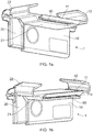
- Figure 1a shows an example of an embodiment of a rail cover 1.
- the rail cover 1 is suitable for covering an underside of a foot 110 of a railway rail 100.
- the rail cover 1 comprises mutually connectable cover parts 10, 20 which are configured to respectively extend at least partially around opposing sides of the foot of the railway rail.
- the mutually connectable cover parts 10, 20 are connectable by an adjustable ratcheting connection 50 to resist separation of the mutually connectable cover parts 10, 20.
- a rail cover 1 is attachable to a railway rail 100 and, more specifically to the foot 110 of a railway rail 100.
- a railway rail 100 when viewed in cross-section, conventionally has a shape including wider sections at the top and bottom and a narrower middle section. These sections are known as the foot (bottom) 110, web (middle) 120 and head (top) 130.
- cables sometimes need to be routed underneath the rail(s).
- a rail cover in accordance with the described embodiments may be implemented.
- FIG. 1a shows an exemplary embodiment of a rail cover 1.
- the rail cover 1 includes two parts; a first cover part 10 and a second cover part 20.
- the two parts 10, 20 are configured to be connectable to each other.
- the two parts 10, 20 may be connected together by various types of connections, including for example a ratcheting connection, opposing racks of interdigitating teeth and/or opposing surfaces, for example, which when connected produce an interference fit, as shown in figure 1a .
- At least one of the mutually connectable parts 10, 20 comprises teeth in the form of a linear rack and an opposing mutually connectable part comprises a protrusion, for example a pawl, configured to allow the connectable parts to be pressed together, but to resist the connectable parts being separated.
- the protrusion may be elastically deformable or may be spring-loaded to encourage engagement with the opposing teeth of the linear rack.
- the teeth of the linear rack are positioned to engage with the protrusion when the connectable parts are connected.
- FIGS. 1b and 1c show alternative views of the rail cover 1 shown in figure 1a .
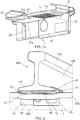
- Figure 2 shows an exemplary embodiment of a rail cover 1 attached to the foot 110 of a rail 100.
- the mutually connectable cover parts 10, 20 include a first cover part 10 including a first connecting portion 11 and a first side portion 12 and a second cover part 20 including a second connecting portion 21 and a second side portion 22.
- the first and second connecting portions 11, 21 are arranged to connect together by the adjustable ratcheting connection 50 which is adjustable to adjust the positions of the first and second cover parts 10, 20 relative to each other.
- the first and second side portions 12, 22 are configured to extend at least partially around opposite sides of the foot 110 of the rail 100 so that, when the first and second connecting portions 11, 21 are connected and pressed together, the first and second side portions 12, 22 hold the rail cover 1 against the foot 110 of the rail 100.
- the first connecting portion 11 may comprise a flat elongate member. According to an embodiment, as shown for example in figure 1c , the first connecting portion 11 defines, on one side, teeth in the form of a linear rack 11a.
- the second connecting portion 21 defines a protrusion 21a, which can be seen in figure 1b , which may resemble one tooth, similar to those of the first connecting portion 11.
- the second connecting portion 21 further defines an arm 21b and support 21c, wherein the arm 21b includes the protrusion 21a, positioned so as to oppose and interdigitate with the teeth of the linear rack 11a and extends substantially in parallel with the first connecting portion 11.
- the support 21c extends, on the opposite side of the first connecting portion 11, substantially in parallel with the first connecting portion 11 also, such that the first connecting portion 11, when the mutually connectable cover parts 10, 20 are connected, is held between the arm 21b and the support 21c.
- the support 21c may for example be made of a relatively rigid/inflexible material and the arm 21b may for example be made of an elastically/resiliently deformable material, so as to allow some flex when the protrusion 21a passes over the linear rack 11a.
- the teeth of the linear rack 11a or the protrusion 21a may be made of an elastically/resiliently deformable material, so as to allow some flex when the protrusion 21a passes over the linear rack 11a.
- the first connecting portion 11 defines teeth in the form of a linear rack 11a, as described above.
- the second connecting portion 21 defines opposing teeth in the form of another linear rack. Therefore, where in the above described embodiment, a single protrusion 21a opposed and interdigitated with the teeth of the linear rack 11a, in this embodiment opposing racks of teeth pass over each other, as the mutually connectable cover parts 10, 20 are connected and the teeth, when connected, interdigitate.
- the second connecting portion 21 comprises an arm defining a surface, which is arranged to oppose the surface of the flat elongated member of the first connecting portion 11, and, when the mutually connectable cover parts 10, 20 are connected, contacts the opposing surface so as to provide an interference fit, which resists the mutually connectable cover parts 10, 20 being separated.
- the rail cover 1 further comprises a first sleeper cover part 15 configured to extend from one edge of the first cover part 10, in a direction perpendicular to a plane in which, in use, the first cover part 10 extends, and is to be positioned adjacent to a rail 100 and against a sleeper 300, so as to cover at least part of the sleeper 300.
- the rail cover 1 further comprises a second sleeper cover part 25 configured to extend from one edge of the second cover part 20, in a direction perpendicular to a plane in which, in use, the second cover part 20 extends, and is to be positioned adjacent to a rail 100 and against a sleeper 300, so as to cover at least part of the sleeper 300.
- the rail cover 1 may be moved between an open position, wherein the connecting parts 10, 20 are sufficiently separated to allow the rail cover 1 to be attached to the foot 110 of the rail 100.
- the connectable parts 10, 20 are then moveable to a closed position, by application of force towards the respective opposing connectable part, wherein the connectable parts 10, 20 move until, at least at a point, sitting flush against either side of the foot 110 of the rail 100.
- the opposing connectable parts 10, 20, produce an interference fit to resist further movement to hold the rail cover 1, in this closed position.
- the rail cover 1 may be positioned to attach to the underside of the foot 110 of the rail 100 adjacent to a railway sleeper 300, which is supporting the rail 100, such that the connecting parts 10, 20 extend along the underside of the rail 100 and the sleeper cover parts 15, 25 extend alongside the sleeper 300. Positioning the rail cover 1 adjacent to a sleeper 300 provides the added benefit that cables 200 extending under the rail 100 will have extra protection from damage.
- the rail cover 1 is preferably made of one or more non-conductive materials, preferably with a high durability.
- nylon 66 may be used for the rail cover 1, or at least one of the mutually connectable cover parts 10, 20.
Landscapes
- Engineering & Computer Science (AREA)
- Architecture (AREA)
- Civil Engineering (AREA)
- Structural Engineering (AREA)
- Electric Cable Arrangement Between Relatively Moving Parts (AREA)
- Train Traffic Observation, Control, And Security (AREA)
Description
- The field of the invention relates to a rail cover and, in particular, to an adjustable rail cover for covering an underside of a foot of a railway rail.
- A common problem in the field of railway design and, in particular, railway rail cabling is how to appropriately manage or organise cables which need to be routed underneath the running rails of a train track. Existing methods of routing cables underneath running rails include clipping the cables to railway sleepers, which support the rails. This technique can be detrimental to the life of the sleepers depending on the methods used to clip the cables to the sleepers and can also take significant time for installation, which in turns raises cost and complexity. Another method for routing cables underneath railway tracks includes laying simple plastic drainpipes underneath the rails as a guide and running cables through the plastic drainpipes. It can however be impossible or very difficult to run cables with plug couplers (plug ends) through such drainpipes as they may be too large or a very tight fit. When cables are run under rails and/or next to sleepers, relative movement between the cables and the rails and/or sleepers can result in wear of the cables and in particular wear of the protective insulation part of the cable. Non-invasive systems for a connection between a railroad track rail and any electrical conductor, for example signal lines, wires or cables, are also known from the prior art. For instance,
US 2008/257973 A1 shows a device for connecting a component to track rail, the device having the form of a rail cover for covering an underside of a foot of a railway rail, the rail cover comprising mutually connectable cover parts configured to respectively extend at least partially around opposing sides of the foot of the railway rail and connectable by an adjustable ratcheting connection to resist separation of the mutually connectable cover parts. - It is therefore desirable to provide a rail cover capable of protecting at least the cable from wear, while not damaging the sleeper or rail. It may be further preferable for the rail cover to be rapidly installable, at a low cost and requiring little or no on-site adaptation during deployment.
- In an embodiment of the present invention there is provided a rail cover for covering an underside of a foot of a railway rail. In accordance with the invention the rail cover comprises mutually connectable cover parts configured to respectively extend at least partially around opposing sides of the foot of the railway rail. The mutually connectable cover parts also being connectable by an adjustable ratcheting connection to resist separation of the mutually connectable cover parts.
- In use, the rail cover comprises two parts which, when attached together, substantially mimic or conform to the shape of the foot of the rail. The two parts may initially be completely separated, prior to attachment to a rail. Alternatively, the two parts may be positioned so that the adjustable ratcheting system is engaged, but the two parts are distanced to pass around at least part of the foot of the rail, so as to be easily connectable to the foot of the rail. This may be described as an open position. The two parts may then be moved to a closed position so that the parts extend around opposing sides of the foot of the rail sufficiently so as to hold the rail cover against the rail.
- An advantage associated with the embodiments is a rapidly installable rail cover, which may be positioned between a rail and a cable, passing under the rail, so as to protect the cable from wear.
- Optionally, the mutually connectable cover parts include a first cover part. The first cover part may include a first connecting portion and a first side portion. The mutually connectable cover parts may further include a second cover part. The second cover part may include a second connecting portion and a second side portion. In an example, the first and second connecting portions are configured to connect together by the adjustable ratcheting connection which is adjustable to adjust the relative positions of the first and second cover parts. The first and second side portions may be configured to extend at least partially around opposite sides of the foot of the rail so that, when the first and second connecting portions are connected and pressed together (moved from the open position to the closed position), the first and second side portions hold the adjustable rail cover against the foot of the rail.
- In a preferred example, the ratcheting connection may be a rack and pawl-type mechanism. Further, preferably, the first and second cover parts may be electrically non-conductive.
- The rack and pawl-type mechanism may preferably be used in order to connect the cover parts together. In an example, the rack may be made to a rigid material and the pawl may be sufficiently flexible to pass over the rack when being connected. The mechanism may be set up to allow for easy connection of the cover parts, but may inhibit separation. Providing electrically non-conductive cover parts has the advantage of an extra layer of protection for any cables running under the rail.
- According to the invention, the rail cover further comprises a first sleeper cover part. The first sleeper cover part is configured to extend from one edge of the first cover part, in a direction perpendicular to a plane in which the first cover part extends, so that, when positioned adjacent to a rail and against a sleeper, covers at least part of the sleeper. Further, the rail cover further comprises a second sleeper cover part. The second sleeper cover part is configured to extend from one edge of the second cover part, in a direction perpendicular to a plane in which the second cover part extends, so that, when positioned adjacent to a rail and against a sleeper, is arranged to cover at least part of the sleeper.
- When viewed along the length axis of the sleeper, the rail cover as described defines an "L" shape. Cables may preferably be positioned to extend under the rail, alongside the sleeper. In this case, in accordance with an embodiment, a sleeper cover may be provided, to be positioned between the cable and the sleeper, so as to provide mutual protection from wear to the cable and the sleeper. The sleeper cover may include first and second parts and may extend along a surface of the sleeper.
- Optionally, the first and second sleeper cover parts may be connectable by another adjustable ratcheting connection, such that, when connected and pressed together, both ratcheting connections are engaged.
- In accordance with this example, the first cover part is connected to or integral with the first sleeper cover part and the second cover part is connected to or integral with the second sleeper cover part. Advantageously, both the first and second cover parts, and the first and second sleeper cover parts, may be connected by a ratcheting connection. This provides additional stability of the cover and further inhibits the parts from separating, meaning the rail cover is held securely in place.
- According to an example, at least one of the first and second connecting portions may be made of a resiliently deformable material.
- In order to allow the mutually connectable cover parts to be connected, the connecting portions may include resiliently deformable material such that the connecting portion including the resiliently deformable material flexes enough for the cover parts to be connected.
- Optionally, the first and second cover parts are made of different materials, respectively. It may be preferable for one of the first and second cover part to be made of a rigid material and the other to be deformable/flexible, to aid connection of the two cover parts.
- Further, according to an embodiment, at least one of the first and second side portions are made of a rigid material. The portions of the rail cover that extend over the sides of the foot of the rail may be rigid as these allow the rail cover to grip or hold the rail, when in use.
- Other advantages associated with embodiments described above include rapid and low cost installation, low cost of the adjustable rail cover and no need for tools to install the cover.
- The invention will hereinafter be described, by way of example only, with reference to the attached drawings, in which:
-
Figures 1a, 1b and1c show perspective views of an exemplary embodiment of a rail cover; -
Figure 2 shows an exemplary embodiment of a rail cover attached to a rail. - Throughout this description any features which are similar to features in other figures have been given the same reference numerals.
- The description below sets forth example rail covers according to this disclosure. Further examples and implementations will be apparent to those having ordinary skill in the art. Further, those having ordinary skill in the art will recognize that various equivalent techniques may be applied in lieu of, or in conjunction with, the examples discussed below, and all such equivalents should be deemed as being encompassed by the present disclosure.
- The arrangements described herein can be implemented in a wide range of devices and systems. However, for ease of explanation, an illustrative example will be described.
- According to one or more embodiments of the invention, there is provided a rail cover capable of providing protection from wear to cables which are to be run from one side of one or more railway rails (rails), underneath the rails, to the other side.
-
Figure 1a shows an example of an embodiment of arail cover 1. As shown, therail cover 1 is suitable for covering an underside of afoot 110 of arailway rail 100. Therail cover 1 comprises mutuallyconnectable cover parts connectable cover parts adjustable ratcheting connection 50 to resist separation of the mutuallyconnectable cover parts - In accordance with an embodiment, a
rail cover 1 is attachable to arailway rail 100 and, more specifically to thefoot 110 of arailway rail 100. Arailway rail 100, when viewed in cross-section, conventionally has a shape including wider sections at the top and bottom and a narrower middle section. These sections are known as the foot (bottom) 110, web (middle) 120 and head (top) 130. In railway infrastructure, cables sometimes need to be routed underneath the rail(s). In order to inhibit the effects of wear on such cables due to relative movement of the cable and rail, a rail cover in accordance with the described embodiments may be implemented. - The
rail cover 1, in use, is attached to thefoot 110 of therail 100, so as to cover the underside.Figure 1a shows an exemplary embodiment of arail cover 1. As shown inFigure 1a , therail cover 1 includes two parts; afirst cover part 10 and asecond cover part 20. The twoparts parts figure 1a . - In the ratcheting connection, in accordance with the example, at least one of the mutually
connectable parts Figures 1b and1c show alternative views of therail cover 1 shown infigure 1a . -
Figure 2 shows an exemplary embodiment of arail cover 1 attached to thefoot 110 of arail 100. As shown, the mutuallyconnectable cover parts first cover part 10 including a first connectingportion 11 and afirst side portion 12 and asecond cover part 20 including a second connectingportion 21 and asecond side portion 22. The first and second connectingportions adjustable ratcheting connection 50 which is adjustable to adjust the positions of the first andsecond cover parts second side portions foot 110 of therail 100 so that, when the first and second connectingportions second side portions rail cover 1 against thefoot 110 of therail 100. - The first connecting
portion 11 may comprise a flat elongate member. According to an embodiment, as shown for example infigure 1c , the first connectingportion 11 defines, on one side, teeth in the form of alinear rack 11a. The second connectingportion 21 defines aprotrusion 21a, which can be seen infigure 1b , which may resemble one tooth, similar to those of the first connectingportion 11. The second connectingportion 21 further defines anarm 21b andsupport 21c, wherein thearm 21b includes theprotrusion 21a, positioned so as to oppose and interdigitate with the teeth of thelinear rack 11a and extends substantially in parallel with the first connectingportion 11. Thesupport 21c extends, on the opposite side of the first connectingportion 11, substantially in parallel with the first connectingportion 11 also, such that the first connectingportion 11, when the mutuallyconnectable cover parts arm 21b and thesupport 21c. - The
support 21c may for example be made of a relatively rigid/inflexible material and thearm 21b may for example be made of an elastically/resiliently deformable material, so as to allow some flex when theprotrusion 21a passes over thelinear rack 11a. - Alternatively, the teeth of the
linear rack 11a or theprotrusion 21a may be made of an elastically/resiliently deformable material, so as to allow some flex when theprotrusion 21a passes over thelinear rack 11a. - In a further exemplary embodiment, the first connecting
portion 11 defines teeth in the form of alinear rack 11a, as described above. The second connectingportion 21 defines opposing teeth in the form of another linear rack. Therefore, where in the above described embodiment, asingle protrusion 21a opposed and interdigitated with the teeth of thelinear rack 11a, in this embodiment opposing racks of teeth pass over each other, as the mutuallyconnectable cover parts - In a further exemplary embodiment, the first connecting
portion 11, which comprises a flat elongated member, defines a surface on at least one side, which may be a flat surface or configured to produce a desired level of friction when in contact with an opposing surface of the second connectingportion 21. The second connectingportion 21 comprises an arm defining a surface, which is arranged to oppose the surface of the flat elongated member of the first connectingportion 11, and, when the mutuallyconnectable cover parts connectable cover parts - According to the invention, the
rail cover 1 further comprises a firstsleeper cover part 15 configured to extend from one edge of thefirst cover part 10, in a direction perpendicular to a plane in which, in use, thefirst cover part 10 extends, and is to be positioned adjacent to arail 100 and against asleeper 300, so as to cover at least part of thesleeper 300. Therail cover 1 further comprises a secondsleeper cover part 25 configured to extend from one edge of thesecond cover part 20, in a direction perpendicular to a plane in which, in use, thesecond cover part 20 extends, and is to be positioned adjacent to arail 100 and against asleeper 300, so as to cover at least part of thesleeper 300. -
Figure 2 further shows an example of arail cover 1 including first and secondsleeper cover parts sleeper 300. As shown, the first andsecond cover parts foot 110 of therail 100 and over the sides of thefoot 110 to hold therail cover 1 in place. The first and secondsleeper cover parts sleeper 300. With this arrangement, thecable 200, which extends next to thesleeper 300 and under therail 100, is offered protection by therail cover 1 from wear caused by relative movement of therail 100,sleeper 300 andcable 200. - In use, the
rail cover 1 may be moved between an open position, wherein the connectingparts rail cover 1 to be attached to thefoot 110 of therail 100. Theconnectable parts connectable parts foot 110 of therail 100. The opposingconnectable parts rail cover 1, in this closed position. - In use, the
rail cover 1 may be moved between an open position, wherein the connectingparts rail cover 1 to be attached to thefoot 110 of therail 100. Theconnectable parts connectable parts foot 110 of therail 100. The opposingconnectable parts rail cover 1, in this closed position. - In an embodiment, the
rail cover 1 may be positioned to attach to the underside of thefoot 110 of therail 100 adjacent to arailway sleeper 300, which is supporting therail 100, such that the connectingparts rail 100 and thesleeper cover parts sleeper 300. Positioning therail cover 1 adjacent to asleeper 300 provides the added benefit thatcables 200 extending under therail 100 will have extra protection from damage. - The
rail cover 1 is preferably made of one or more non-conductive materials, preferably with a high durability. For example nylon 66 may be used for therail cover 1, or at least one of the mutuallyconnectable cover parts - According to the above examples, it is possible to reduce wear of cables directed under the rail, for example by positioning the
rail cover 1 between thecable 200 and therail 100.
Claims (8)
- A rail cover (1) for covering an underside of a foot (110) of a railway rail (100), the rail cover comprising:
mutually connectable cover parts (10, 20) configured to respectively extend at least partially around opposing sides of the foot (110) of the railway rail (100) and connectable by an adjustable ratcheting connection (50) to resist separation of the mutually connectable cover parts; and characterised by:a first sleeper cover part (15) configured to extend from one edge of a first cover part (10), in a direction perpendicular to a plane in which, in use, the first cover part (10) extends, so that, when positioned adjacent to a rail (100) and against a sleeper (300), covers at least part of the sleeper; and/ora second sleeper cover part (25) configured to extend from one edge of a second cover part (20), in a direction perpendicular to a plane in which, in use, the second cover part extends, so that, when positioned adjacent to a rail (100) and against a sleeper (300) is arranged to cover at least part of the sleeper. - The rail cover according to claim 1,
the first cover part (10) including a first connecting portion (11) and a first side portion (12); and
the second cover part (20) including a second connecting portion (21) and a second side portion (22);
the first and second connecting portions being configured to connect together by the adjustable ratcheting connection (50) which is adjustable to adjust the relative positions of the first and second cover parts, and
the first and second side portions being configured to extend at least partially around opposite sides of the foot (110) of the rail (100) so that, when the first and second connecting portions are connected and pressed together, the first and second side portions hold the adjustable rail cover against the foot of the rail. - The rail cover according to claim 1 or 2, wherein the ratcheting connection (50) is a rack and pawl-type mechanism.
- The rail cover according to any preceding claim, wherein the first and second cover parts (10, 20) are electrically non-conductive.
- The rail cover according to any preceding claim, wherein the first and second sleeper cover parts (15, 25) are connectable by another adjustable ratcheting connection, such that, when connected and pressed together, both adjustable ratcheting connections are engaged.
- The rail cover according to any preceding claim, wherein at least one of the first and second connecting portions (11, 21) are made of a resiliently deformable material.
- The rail cover according to any preceding claim, wherein the first and second cover parts (10, 20) are made of different materials, respectively.
- The rail cover according to any preceding claim, wherein at least one of the first and second side portions (12, 22) are made of a rigid material.
Priority Applications (1)
| Application Number | Priority Date | Filing Date | Title |
|---|---|---|---|
| PL19156374T PL3536854T3 (en) | 2018-03-07 | 2019-02-11 | Rail cover |
Applications Claiming Priority (1)
| Application Number | Priority Date | Filing Date | Title |
|---|---|---|---|
| GB1803617.8A GB2571739B (en) | 2018-03-07 | 2018-03-07 | Rail cover |
Publications (2)
| Publication Number | Publication Date |
|---|---|
| EP3536854A1 EP3536854A1 (en) | 2019-09-11 |
| EP3536854B1 true EP3536854B1 (en) | 2021-03-31 |
Family
ID=61903606
Family Applications (1)
| Application Number | Title | Priority Date | Filing Date |
|---|---|---|---|
| EP19156374.1A Active EP3536854B1 (en) | 2018-03-07 | 2019-02-11 | Rail cover |
Country Status (7)
| Country | Link |
|---|---|
| US (1) | US11401663B2 (en) |
| EP (1) | EP3536854B1 (en) |
| AU (1) | AU2019200700B2 (en) |
| DK (1) | DK3536854T3 (en) |
| ES (1) | ES2874644T3 (en) |
| GB (1) | GB2571739B (en) |
| PL (1) | PL3536854T3 (en) |
Cited By (1)
| Publication number | Priority date | Publication date | Assignee | Title |
|---|---|---|---|---|
| EP4733477A1 (en) | 2024-10-23 | 2026-04-29 | HellermannTyton Data Limited | Rail cover cable guard made of identical pieces |
Family Cites Families (14)
| Publication number | Priority date | Publication date | Assignee | Title |
|---|---|---|---|---|
| US1665187A (en) * | 1926-08-02 | 1928-04-03 | J F Mcvicker | Rail anchor |
| US1758282A (en) * | 1929-07-02 | 1930-05-13 | Joseph D Gatch | Rail chair |
| US3927742A (en) * | 1974-10-23 | 1975-12-23 | Clarke Reynolds | Third rail cover board |
| US4826078A (en) * | 1987-11-13 | 1989-05-02 | Imo Delaval Inc. | Wire-to-track-base retainer clip and keeper |
| DE9003837U1 (en) | 1990-04-03 | 1990-06-07 | Scheidt & Bachmann GmbH, 4050 Mönchengladbach | Device for laying cables at the foot of railway tracks |
| DE19935562C2 (en) | 1998-08-04 | 2000-12-14 | Krone Gmbh | Rail foot clamp |
| JP3951234B2 (en) * | 2003-01-16 | 2007-08-01 | 大鉄工業株式会社 | Lifeline fitting |
| US7992797B2 (en) * | 2007-04-18 | 2011-08-09 | Fastrax Industries, Inc. | Railroad signal line attachment clip |
| DE202013003686U1 (en) * | 2013-04-19 | 2014-04-22 | Hellermanntyton Gmbh | Rail clamping device |
| DE102013216769B4 (en) | 2013-08-23 | 2017-07-27 | BSH Hausgeräte GmbH | Refrigerating appliance with a door rack |
| WO2015124834A1 (en) * | 2014-02-21 | 2015-08-27 | Miika Kavonius | Railmark |
| US10472774B2 (en) * | 2015-12-05 | 2019-11-12 | Grace Industries, Inc. | Railroad bracket |
| GB2554073B (en) * | 2016-09-14 | 2019-10-02 | Pandrol Vortok Ltd | Cable management assembly |
| RU175599U1 (en) * | 2017-08-04 | 2017-12-12 | Андрей Игоревич Кузнецов | Device for electrical connection of a cable to a rail |
-
2018
- 2018-03-07 GB GB1803617.8A patent/GB2571739B/en not_active Expired - Fee Related
-
2019
- 2019-02-01 AU AU2019200700A patent/AU2019200700B2/en active Active
- 2019-02-11 PL PL19156374T patent/PL3536854T3/en unknown
- 2019-02-11 ES ES19156374T patent/ES2874644T3/en active Active
- 2019-02-11 DK DK19156374.1T patent/DK3536854T3/en active
- 2019-02-11 EP EP19156374.1A patent/EP3536854B1/en active Active
- 2019-02-14 US US16/275,990 patent/US11401663B2/en active Active
Non-Patent Citations (1)
| Title |
|---|
| None * |
Cited By (1)
| Publication number | Priority date | Publication date | Assignee | Title |
|---|---|---|---|---|
| EP4733477A1 (en) | 2024-10-23 | 2026-04-29 | HellermannTyton Data Limited | Rail cover cable guard made of identical pieces |
Also Published As
| Publication number | Publication date |
|---|---|
| DK3536854T3 (en) | 2021-06-07 |
| GB201803617D0 (en) | 2018-04-18 |
| US20190276986A1 (en) | 2019-09-12 |
| AU2019200700B2 (en) | 2024-11-21 |
| EP3536854A1 (en) | 2019-09-11 |
| GB2571739A (en) | 2019-09-11 |
| ES2874644T3 (en) | 2021-11-05 |
| GB2571739B (en) | 2022-05-25 |
| AU2019200700A1 (en) | 2019-09-26 |
| US11401663B2 (en) | 2022-08-02 |
| PL3536854T3 (en) | 2021-11-02 |
Similar Documents
| Publication | Publication Date | Title |
|---|---|---|
| US7992797B2 (en) | Railroad signal line attachment clip | |
| IL204527A (en) | System for fastening a rail and tensioning clamp for a system to this type | |
| EP3536854B1 (en) | Rail cover | |
| US8157185B2 (en) | Strike attachment railroad signal line connector | |
| US4826078A (en) | Wire-to-track-base retainer clip and keeper | |
| EP3296461A1 (en) | Cable management assembly | |
| EP2754214B1 (en) | Support and retaining device for wires and cables | |
| CN101142727A (en) | Bus bracket | |
| NZ750651A (en) | Rail cover | |
| JPH0658556U (en) | Branch connection mechanism for electrical leads | |
| KR20110080825A (en) | Electric heating device for railway branch and its installation method | |
| JP7049193B2 (en) | Cable protective cover | |
| JP7488417B2 (en) | Heat-conducting clamp device for melting snow at the bottom of rails on railway crossings | |
| EP4733477A1 (en) | Rail cover cable guard made of identical pieces | |
| CN111799721B (en) | Cable Fixtures, Electrical Boxes and Electrical Equipment | |
| WO2018193253A1 (en) | A non-intrusive turnout system for a railway track | |
| GB2428723A (en) | An insulating cover for an electrifiable railway rail | |
| US6604689B1 (en) | Railroad communication tie | |
| CA2629195C (en) | Railroad signal line attachment clip | |
| US900958A (en) | Safety appliance for electric railways. | |
| US1665629A (en) | Bootleg | |
| PL235179B1 (en) | Balise fastening | |
| US1261578A (en) | Electrical contact-shoe. | |
| KR20080110948A (en) | Clip for fixing the wiring of the vehicle | |
| HK1199429B (en) | Segmented collector shoe assembly |
Legal Events
| Date | Code | Title | Description |
|---|---|---|---|
| PUAI | Public reference made under article 153(3) epc to a published international application that has entered the european phase |
Free format text: ORIGINAL CODE: 0009012 |
|
| STAA | Information on the status of an ep patent application or granted ep patent |
Free format text: STATUS: THE APPLICATION HAS BEEN PUBLISHED |
|
| AK | Designated contracting states |
Kind code of ref document: A1 Designated state(s): AL AT BE BG CH CY CZ DE DK EE ES FI FR GB GR HR HU IE IS IT LI LT LU LV MC MK MT NL NO PL PT RO RS SE SI SK SM TR |
|
| AX | Request for extension of the european patent |
Extension state: BA ME |
|
| STAA | Information on the status of an ep patent application or granted ep patent |
Free format text: STATUS: REQUEST FOR EXAMINATION WAS MADE |
|
| 17P | Request for examination filed |
Effective date: 20200123 |
|
| RBV | Designated contracting states (corrected) |
Designated state(s): AL AT BE BG CH CY CZ DE DK EE ES FI FR GB GR HR HU IE IS IT LI LT LU LV MC MK MT NL NO PL PT RO RS SE SI SK SM TR |
|
| RIC1 | Information provided on ipc code assigned before grant |
Ipc: B60M 5/00 20060101ALN20200529BHEP Ipc: H01R 4/64 20060101ALN20200529BHEP Ipc: E01B 26/00 20060101AFI20200529BHEP |
|
| RIC1 | Information provided on ipc code assigned before grant |
Ipc: B60M 5/00 20060101ALN20200609BHEP Ipc: E01B 26/00 20060101AFI20200609BHEP Ipc: H01R 4/64 20060101ALN20200609BHEP |
|
| GRAP | Despatch of communication of intention to grant a patent |
Free format text: ORIGINAL CODE: EPIDOSNIGR1 |
|
| STAA | Information on the status of an ep patent application or granted ep patent |
Free format text: STATUS: GRANT OF PATENT IS INTENDED |
|
| GRAJ | Information related to disapproval of communication of intention to grant by the applicant or resumption of examination proceedings by the epo deleted |
Free format text: ORIGINAL CODE: EPIDOSDIGR1 |
|
| STAA | Information on the status of an ep patent application or granted ep patent |
Free format text: STATUS: REQUEST FOR EXAMINATION WAS MADE |
|
| INTG | Intention to grant announced |
Effective date: 20200731 |
|
| INTG | Intention to grant announced |
Effective date: 20200731 |
|
| INTC | Intention to grant announced (deleted) | ||
| RIC1 | Information provided on ipc code assigned before grant |
Ipc: B60M 5/00 20060101ALN20200804BHEP Ipc: E01B 26/00 20060101AFI20200804BHEP Ipc: H01R 4/64 20060101ALN20200804BHEP |
|
| GRAP | Despatch of communication of intention to grant a patent |
Free format text: ORIGINAL CODE: EPIDOSNIGR1 |
|
| STAA | Information on the status of an ep patent application or granted ep patent |
Free format text: STATUS: GRANT OF PATENT IS INTENDED |
|
| INTG | Intention to grant announced |
Effective date: 20200928 |
|
| GRAS | Grant fee paid |
Free format text: ORIGINAL CODE: EPIDOSNIGR3 |
|
| GRAA | (expected) grant |
Free format text: ORIGINAL CODE: 0009210 |
|
| STAA | Information on the status of an ep patent application or granted ep patent |
Free format text: STATUS: THE PATENT HAS BEEN GRANTED |
|
| AK | Designated contracting states |
Kind code of ref document: B1 Designated state(s): AL AT BE BG CH CY CZ DE DK EE ES FI FR GB GR HR HU IE IS IT LI LT LU LV MC MK MT NL NO PL PT RO RS SE SI SK SM TR |
|
| REG | Reference to a national code |
Ref country code: GB Ref legal event code: FG4D Ref country code: CH Ref legal event code: EP |
|
| REG | Reference to a national code |
Ref country code: AT Ref legal event code: REF Ref document number: 1377058 Country of ref document: AT Kind code of ref document: T Effective date: 20210415 |
|
| REG | Reference to a national code |
Ref country code: DE Ref legal event code: R096 Ref document number: 602019003482 Country of ref document: DE |
|
| REG | Reference to a national code |
Ref country code: IE Ref legal event code: FG4D |
|
| REG | Reference to a national code |
Ref country code: SE Ref legal event code: TRGR |
|
| REG | Reference to a national code |
Ref country code: DK Ref legal event code: T3 Effective date: 20210603 |
|
| REG | Reference to a national code |
Ref country code: NL Ref legal event code: FP |
|
| REG | Reference to a national code |
Ref country code: LT Ref legal event code: MG9D |
|
| PG25 | Lapsed in a contracting state [announced via postgrant information from national office to epo] |
Ref country code: BG Free format text: LAPSE BECAUSE OF FAILURE TO SUBMIT A TRANSLATION OF THE DESCRIPTION OR TO PAY THE FEE WITHIN THE PRESCRIBED TIME-LIMIT Effective date: 20210630 Ref country code: FI Free format text: LAPSE BECAUSE OF FAILURE TO SUBMIT A TRANSLATION OF THE DESCRIPTION OR TO PAY THE FEE WITHIN THE PRESCRIBED TIME-LIMIT Effective date: 20210331 Ref country code: HR Free format text: LAPSE BECAUSE OF FAILURE TO SUBMIT A TRANSLATION OF THE DESCRIPTION OR TO PAY THE FEE WITHIN THE PRESCRIBED TIME-LIMIT Effective date: 20210331 |
|
| PG25 | Lapsed in a contracting state [announced via postgrant information from national office to epo] |
Ref country code: LV Free format text: LAPSE BECAUSE OF FAILURE TO SUBMIT A TRANSLATION OF THE DESCRIPTION OR TO PAY THE FEE WITHIN THE PRESCRIBED TIME-LIMIT Effective date: 20210331 Ref country code: RS Free format text: LAPSE BECAUSE OF FAILURE TO SUBMIT A TRANSLATION OF THE DESCRIPTION OR TO PAY THE FEE WITHIN THE PRESCRIBED TIME-LIMIT Effective date: 20210331 |
|
| REG | Reference to a national code |
Ref country code: NO Ref legal event code: T2 Effective date: 20210331 |
|
| PG25 | Lapsed in a contracting state [announced via postgrant information from national office to epo] |
Ref country code: SM Free format text: LAPSE BECAUSE OF FAILURE TO SUBMIT A TRANSLATION OF THE DESCRIPTION OR TO PAY THE FEE WITHIN THE PRESCRIBED TIME-LIMIT Effective date: 20210331 Ref country code: EE Free format text: LAPSE BECAUSE OF FAILURE TO SUBMIT A TRANSLATION OF THE DESCRIPTION OR TO PAY THE FEE WITHIN THE PRESCRIBED TIME-LIMIT Effective date: 20210331 Ref country code: LT Free format text: LAPSE BECAUSE OF FAILURE TO SUBMIT A TRANSLATION OF THE DESCRIPTION OR TO PAY THE FEE WITHIN THE PRESCRIBED TIME-LIMIT Effective date: 20210331 |
|
| REG | Reference to a national code |
Ref country code: ES Ref legal event code: FG2A Ref document number: 2874644 Country of ref document: ES Kind code of ref document: T3 Effective date: 20211105 |
|
| PG25 | Lapsed in a contracting state [announced via postgrant information from national office to epo] |
Ref country code: IS Free format text: LAPSE BECAUSE OF FAILURE TO SUBMIT A TRANSLATION OF THE DESCRIPTION OR TO PAY THE FEE WITHIN THE PRESCRIBED TIME-LIMIT Effective date: 20210731 Ref country code: SK Free format text: LAPSE BECAUSE OF FAILURE TO SUBMIT A TRANSLATION OF THE DESCRIPTION OR TO PAY THE FEE WITHIN THE PRESCRIBED TIME-LIMIT Effective date: 20210331 Ref country code: RO Free format text: LAPSE BECAUSE OF FAILURE TO SUBMIT A TRANSLATION OF THE DESCRIPTION OR TO PAY THE FEE WITHIN THE PRESCRIBED TIME-LIMIT Effective date: 20210331 Ref country code: PT Free format text: LAPSE BECAUSE OF FAILURE TO SUBMIT A TRANSLATION OF THE DESCRIPTION OR TO PAY THE FEE WITHIN THE PRESCRIBED TIME-LIMIT Effective date: 20210802 |
|
| REG | Reference to a national code |
Ref country code: DE Ref legal event code: R097 Ref document number: 602019003482 Country of ref document: DE |
|
| PG25 | Lapsed in a contracting state [announced via postgrant information from national office to epo] |
Ref country code: AL Free format text: LAPSE BECAUSE OF FAILURE TO SUBMIT A TRANSLATION OF THE DESCRIPTION OR TO PAY THE FEE WITHIN THE PRESCRIBED TIME-LIMIT Effective date: 20210331 |
|
| PLBE | No opposition filed within time limit |
Free format text: ORIGINAL CODE: 0009261 |
|
| STAA | Information on the status of an ep patent application or granted ep patent |
Free format text: STATUS: NO OPPOSITION FILED WITHIN TIME LIMIT |
|
| 26N | No opposition filed |
Effective date: 20220104 |
|
| PG25 | Lapsed in a contracting state [announced via postgrant information from national office to epo] |
Ref country code: IS Free format text: LAPSE BECAUSE OF FAILURE TO SUBMIT A TRANSLATION OF THE DESCRIPTION OR TO PAY THE FEE WITHIN THE PRESCRIBED TIME-LIMIT Effective date: 20210731 |
|
| PG25 | Lapsed in a contracting state [announced via postgrant information from national office to epo] |
Ref country code: MC Free format text: LAPSE BECAUSE OF FAILURE TO SUBMIT A TRANSLATION OF THE DESCRIPTION OR TO PAY THE FEE WITHIN THE PRESCRIBED TIME-LIMIT Effective date: 20210331 |
|
| PG25 | Lapsed in a contracting state [announced via postgrant information from national office to epo] |
Ref country code: LU Free format text: LAPSE BECAUSE OF NON-PAYMENT OF DUE FEES Effective date: 20220211 |
|
| REG | Reference to a national code |
Ref country code: AT Ref legal event code: UEP Ref document number: 1377058 Country of ref document: AT Kind code of ref document: T Effective date: 20210331 |
|
| P01 | Opt-out of the competence of the unified patent court (upc) registered |
Effective date: 20230330 |
|
| PG25 | Lapsed in a contracting state [announced via postgrant information from national office to epo] |
Ref country code: MK Free format text: LAPSE BECAUSE OF FAILURE TO SUBMIT A TRANSLATION OF THE DESCRIPTION OR TO PAY THE FEE WITHIN THE PRESCRIBED TIME-LIMIT Effective date: 20210331 Ref country code: CY Free format text: LAPSE BECAUSE OF FAILURE TO SUBMIT A TRANSLATION OF THE DESCRIPTION OR TO PAY THE FEE WITHIN THE PRESCRIBED TIME-LIMIT Effective date: 20210331 |
|
| PG25 | Lapsed in a contracting state [announced via postgrant information from national office to epo] |
Ref country code: HU Free format text: LAPSE BECAUSE OF FAILURE TO SUBMIT A TRANSLATION OF THE DESCRIPTION OR TO PAY THE FEE WITHIN THE PRESCRIBED TIME-LIMIT; INVALID AB INITIO Effective date: 20190211 |
|
| PG25 | Lapsed in a contracting state [announced via postgrant information from national office to epo] |
Ref country code: TR Free format text: LAPSE BECAUSE OF FAILURE TO SUBMIT A TRANSLATION OF THE DESCRIPTION OR TO PAY THE FEE WITHIN THE PRESCRIBED TIME-LIMIT Effective date: 20210331 |
|
| PG25 | Lapsed in a contracting state [announced via postgrant information from national office to epo] |
Ref country code: MT Free format text: LAPSE BECAUSE OF FAILURE TO SUBMIT A TRANSLATION OF THE DESCRIPTION OR TO PAY THE FEE WITHIN THE PRESCRIBED TIME-LIMIT Effective date: 20210331 |
|
| PG25 | Lapsed in a contracting state [announced via postgrant information from national office to epo] |
Ref country code: GR Free format text: LAPSE BECAUSE OF NON-PAYMENT OF DUE FEES Effective date: 20210331 |
|
| PG25 | Lapsed in a contracting state [announced via postgrant information from national office to epo] |
Ref country code: GR Free format text: LAPSE BECAUSE OF NON-PAYMENT OF DUE FEES Effective date: 20210331 |
|
| PGFP | Annual fee paid to national office [announced via postgrant information from national office to epo] |
Ref country code: PL Payment date: 20251229 Year of fee payment: 8 |
|
| REG | Reference to a national code |
Ref country code: CH Ref legal event code: U11 Free format text: ST27 STATUS EVENT CODE: U-0-0-U10-U11 (AS PROVIDED BY THE NATIONAL OFFICE) Effective date: 20260301 |
|
| PGFP | Annual fee paid to national office [announced via postgrant information from national office to epo] |
Ref country code: NL Payment date: 20260226 Year of fee payment: 8 |
|
| PGFP | Annual fee paid to national office [announced via postgrant information from national office to epo] |
Ref country code: SE Payment date: 20260225 Year of fee payment: 8 |
|
| PGFP | Annual fee paid to national office [announced via postgrant information from national office to epo] |
Ref country code: GB Payment date: 20260226 Year of fee payment: 8 |
|
| PGFP | Annual fee paid to national office [announced via postgrant information from national office to epo] |
Ref country code: ES Payment date: 20260311 Year of fee payment: 8 |
|
| PGFP | Annual fee paid to national office [announced via postgrant information from national office to epo] |
Ref country code: DE Payment date: 20260226 Year of fee payment: 8 Ref country code: DK Payment date: 20260226 Year of fee payment: 8 Ref country code: NO Payment date: 20260127 Year of fee payment: 8 Ref country code: IE Payment date: 20260122 Year of fee payment: 8 |
|
| PGFP | Annual fee paid to national office [announced via postgrant information from national office to epo] |
Ref country code: AT Payment date: 20260126 Year of fee payment: 8 |
|
| PGFP | Annual fee paid to national office [announced via postgrant information from national office to epo] |
Ref country code: BE Payment date: 20260123 Year of fee payment: 8 Ref country code: IT Payment date: 20260210 Year of fee payment: 8 |
|
| PGFP | Annual fee paid to national office [announced via postgrant information from national office to epo] |
Ref country code: FR Payment date: 20260122 Year of fee payment: 8 |
|
| PGFP | Annual fee paid to national office [announced via postgrant information from national office to epo] |
Ref country code: CH Payment date: 20260301 Year of fee payment: 8 Ref country code: CZ Payment date: 20260115 Year of fee payment: 8 |