EP3536609A1 - Failure detection system - Google Patents
Failure detection system Download PDFInfo
- Publication number
- EP3536609A1 EP3536609A1 EP18171730.7A EP18171730A EP3536609A1 EP 3536609 A1 EP3536609 A1 EP 3536609A1 EP 18171730 A EP18171730 A EP 18171730A EP 3536609 A1 EP3536609 A1 EP 3536609A1
- Authority
- EP
- European Patent Office
- Prior art keywords
- fds
- gearbox
- processor
- gear
- optical representation
- Prior art date
- Legal status (The legal status is an assumption and is not a legal conclusion. Google has not performed a legal analysis and makes no representation as to the accuracy of the status listed.)
- Granted
Links
Images




Classifications
-
- B—PERFORMING OPERATIONS; TRANSPORTING
- B64—AIRCRAFT; AVIATION; COSMONAUTICS
- B64C—AEROPLANES; HELICOPTERS
- B64C27/00—Rotorcraft; Rotors peculiar thereto
- B64C27/006—Safety devices
-
- G—PHYSICS
- G07—CHECKING-DEVICES
- G07C—TIME OR ATTENDANCE REGISTERS; REGISTERING OR INDICATING THE WORKING OF MACHINES; GENERATING RANDOM NUMBERS; VOTING OR LOTTERY APPARATUS; ARRANGEMENTS, SYSTEMS OR APPARATUS FOR CHECKING NOT PROVIDED FOR ELSEWHERE
- G07C5/00—Registering or indicating the working of vehicles
- G07C5/08—Registering or indicating performance data other than driving, working, idle, or waiting time, with or without registering driving, working, idle or waiting time
- G07C5/0808—Diagnosing performance data
-
- B—PERFORMING OPERATIONS; TRANSPORTING
- B64—AIRCRAFT; AVIATION; COSMONAUTICS
- B64D—EQUIPMENT FOR FITTING IN OR TO AIRCRAFT; FLIGHT SUITS; PARACHUTES; ARRANGEMENT OR MOUNTING OF POWER PLANTS OR PROPULSION TRANSMISSIONS IN AIRCRAFT
- B64D35/00—Transmitting power from power plants to propellers or rotors; Arrangements of transmissions
-
- F—MECHANICAL ENGINEERING; LIGHTING; HEATING; WEAPONS; BLASTING
- F16—ENGINEERING ELEMENTS AND UNITS; GENERAL MEASURES FOR PRODUCING AND MAINTAINING EFFECTIVE FUNCTIONING OF MACHINES OR INSTALLATIONS; THERMAL INSULATION IN GENERAL
- F16H—GEARING
- F16H57/00—General details of gearing
- F16H57/01—Monitoring wear or stress of gearing elements, e.g. for triggering maintenance
-
- F—MECHANICAL ENGINEERING; LIGHTING; HEATING; WEAPONS; BLASTING
- F16—ENGINEERING ELEMENTS AND UNITS; GENERAL MEASURES FOR PRODUCING AND MAINTAINING EFFECTIVE FUNCTIONING OF MACHINES OR INSTALLATIONS; THERMAL INSULATION IN GENERAL
- F16H—GEARING
- F16H57/00—General details of gearing
- F16H57/08—General details of gearing of gearings with members having orbital motion
- F16H57/082—Planet carriers
-
- G—PHYSICS
- G06—COMPUTING OR CALCULATING; COUNTING
- G06T—IMAGE DATA PROCESSING OR GENERATION, IN GENERAL
- G06T7/00—Image analysis
- G06T7/0002—Inspection of images, e.g. flaw detection
- G06T7/0004—Industrial image inspection
- G06T7/001—Industrial image inspection using an image reference approach
-
- B—PERFORMING OPERATIONS; TRANSPORTING
- B64—AIRCRAFT; AVIATION; COSMONAUTICS
- B64D—EQUIPMENT FOR FITTING IN OR TO AIRCRAFT; FLIGHT SUITS; PARACHUTES; ARRANGEMENT OR MOUNTING OF POWER PLANTS OR PROPULSION TRANSMISSIONS IN AIRCRAFT
- B64D45/00—Aircraft indicators or protectors not otherwise provided for
- B64D2045/0085—Devices for aircraft health monitoring, e.g. monitoring flutter or vibration
-
- F—MECHANICAL ENGINEERING; LIGHTING; HEATING; WEAPONS; BLASTING
- F16—ENGINEERING ELEMENTS AND UNITS; GENERAL MEASURES FOR PRODUCING AND MAINTAINING EFFECTIVE FUNCTIONING OF MACHINES OR INSTALLATIONS; THERMAL INSULATION IN GENERAL
- F16H—GEARING
- F16H1/00—Toothed gearings for conveying rotary motion
- F16H1/28—Toothed gearings for conveying rotary motion with gears having orbital motion
-
- F—MECHANICAL ENGINEERING; LIGHTING; HEATING; WEAPONS; BLASTING
- F16—ENGINEERING ELEMENTS AND UNITS; GENERAL MEASURES FOR PRODUCING AND MAINTAINING EFFECTIVE FUNCTIONING OF MACHINES OR INSTALLATIONS; THERMAL INSULATION IN GENERAL
- F16H—GEARING
- F16H57/00—General details of gearing
- F16H57/01—Monitoring wear or stress of gearing elements, e.g. for triggering maintenance
- F16H2057/012—Monitoring wear or stress of gearing elements, e.g. for triggering maintenance of gearings
-
- F—MECHANICAL ENGINEERING; LIGHTING; HEATING; WEAPONS; BLASTING
- F16—ENGINEERING ELEMENTS AND UNITS; GENERAL MEASURES FOR PRODUCING AND MAINTAINING EFFECTIVE FUNCTIONING OF MACHINES OR INSTALLATIONS; THERMAL INSULATION IN GENERAL
- F16H—GEARING
- F16H61/00—Control functions within control units of change-speed- or reversing-gearings for conveying rotary motion ; Control of exclusively fluid gearing, friction gearing, gearings with endless flexible members or other particular types of gearing
- F16H61/12—Detecting malfunction or potential malfunction, e.g. fail safe ; Circumventing or fixing failures
- F16H2061/1208—Detecting malfunction or potential malfunction, e.g. fail safe ; Circumventing or fixing failures with diagnostic check cycles; Monitoring of failures
-
- G—PHYSICS
- G06—COMPUTING OR CALCULATING; COUNTING
- G06T—IMAGE DATA PROCESSING OR GENERATION, IN GENERAL
- G06T2207/00—Indexing scheme for image analysis or image enhancement
- G06T2207/30—Subject of image; Context of image processing
- G06T2207/30108—Industrial image inspection
- G06T2207/30164—Workpiece; Machine component
Definitions
- Aircraft such as helicopters commonly comprise power trains, gear trains, planetary gearsets, and/or many other mechanical systems that utilize bearings.
- the bearings often comprise inner and outer races along which bearing elements roll.
- the races of bearings can be damaged by fatigue or by exposure to other solids being inadvertently being introduced between the bearing elements and the races of the bearings. Regardless the cause, damaged bearing races can sometimes pose potentially catastrophic failure of larger systems.
- bearing failure detection is attempted by using chip detectors that monitor for the existence of undesirable pieces of metal.
- chip detectors are not well-suited for providing confirmation as to whether a detected chip is associated with a failing bearing as opposed to any other source of a chip (such as a gear tooth or a machining chip). Accordingly, there is a need for detecting bearing failures as compared to simply indicating an existence of undesirable chip content.
- FIG 1 shows a rotorcraft 100 according to one example embodiment.
- Rotorcraft 100 features power train system 110, main rotor blades 120, tail rotor blades 120', a fuselage 130, a landing gear 140, and an empennage 150.
- Power train system 110 may rotate blades 120 and/or blades 120'.
- Figure 2 shows the power train system 110 of Figure 1 .
- power train system 110 includes an engine 112, a gearbox 160, a rotor mast 114, and a tail rotor drive shaft 116.
- Engine 112 supplies torque to mast 114, via gearbox 160, for rotating of blades 120.
- Engine 112 also supplies torque to tail rotor drive shaft 116 for rotating blades 120'.
- gearbox 160 is a main rotor transmission system. Teachings of certain embodiments recognize, however, that power train system 110 may include more or different gearboxes than gearbox 160 shown in Figure 1 .
- Power train system 110 may include a control system for selectively controlling the pitch of each blade 120 to selectively control direction, thrust, and lift of rotorcraft 100.
- Fuselage 130 represents the body of rotorcraft 100 and may be coupled to power train system 110 such that power train system 110 and blades 120 may move fuselage 130 through the air.
- Landing gear 140 supports rotorcraft 100 when rotorcraft 100 is landing and/or when rotorcraft 100 is at rest on the ground.
- Empennage 150 represents the tail section of the aircraft and features blades 120'.
- Power train system 110 and blades 120' may collectively provide thrust in the same direction as the rotation of blades 120 to counter the torque effect created by blades 120.
- teachings from rotorcraft 100 may apply to aircraft other than rotorcraft, such as airplanes, tilt rotors, and unmanned aircraft, to name a few examples.
- teachings of certain embodiments relating to rotor systems described herein may apply to power train system 110 and/or other power train systems, including but not limited to non-rotorcraft power train systems.
- gearbox 160 transmits power from a power source (e.g., engine 112) to an object or objects to be moved (e.g., blades 120).
- Gearbox 160 converts speed and torque between the power source and the object(s) to be moved.
- Gearbox 160 may be configured to reduce the speed of the rotational output of engine 112, while increasing the torque applied to blades 120.
- FIG. 3 shows a gearbox 160 according to one example embodiment.
- gearbox 160 is a main rotor gearbox and includes a rotor mast 114.
- Gearbox 160 also includes at least one gearbox housing 180 and various gears contained therein (see Figures 4 and 5 ).
- a gear is a rotating part having teeth that mesh with another toothed part to transmit rotational energy.
- the gears within gearbox 160 accomplish speed and torque conversions that are desired for a given implementation. For instance, the gearbox 160 of Figures 3 reduces rotational speed while multiplying the torque output, which is applied to blades 120 of rotorcraft 100.
- Figures 4 and 5 illustrate a gear train 161 contained within gearbox housing 180.
- gear train 161 includes an input pinion 162.
- Input pinion 162 is in mechanical communication with, and receives rotational energy from, a power source (e.g., engine 112).
- Input pinion 162 includes a helical bevel gear portion 163.
- the helical bevel gear portion 163 of input pinion 162 meshes with, and transmits rotational energy to, bevel gear 164.
- Bevel gear 164 is a helical bevel gear.
- Bevel gear 164 meshes with and drives an accessory drive gear 190, which is configured to provide rotational energy to an accessory gearbox (not shown) and/or various aircraft accessories, such as air blowers, cooling fans, lubrication pumps, hydraulic pumps, electrical generators, and similar components and systems (not shown).
- Bevel gear 164 is attached via a common shaft 165 to helical spur gear 166.
- bevel gear 164, common shaft 165, and helical spur gear 166 rotate together about a common axis.
- Torque applied to bevel gear 164 is transmitted via common shaft 165 to helical spur gear 166.
- Helical spur gear 166 meshes with, and transmits rotational energy to, bull gear 167.
- Bull gear 167 is integral with sun gear 171 (see Figure 5 ) of planetary gear set 170. Thus, torque applied to bull gear 167 is transmitted to sun gear 171.
- gear train 161 includes a second input pinion 162', which may be configured to receive rotational energy from a second power source (e.g., a second engine 112).
- Second input pinion 162' includes a helical bevel gear portion 163'.
- the helical bevel gear portion 163' of second input pinion 162' meshes with, and transmits rotational energy to, a second bevel gear 164'.
- second bevel gear 164' is a helical bevel gear.
- Second bevel gear 164' meshes with and drives a second accessory drive gear 190', which is configured to provide rotational energy to an accessory gearbox (not shown) and/or various aircraft accessories, such as air blowers, cooling fans, lubrication pumps, hydraulic pumps, electrical generators, and similar components and systems (not shown).
- Second bevel gear 164' is attached via a second common shaft 165' to a second helical spur gear 166'.
- second bevel gear 164', second common shaft 165', and second helical spur gear 166' rotate together about a common axis. Torque applied to second bevel gear 164' is transmitted via second common shaft 165' to second helical spur gear 166'.
- Second helical spur gear 166' meshes with, and transmits rotational energy to, bull gear 167, which is integral with sun gear 171 (see Figure 5 ). Accordingly, rotational energy provided at either or both input pinions 162, 162' is ultimately combined at bull gear 167 and transmitted to sun gear 171.
- Figure 5 depicts the planetary gear set 170 within gear train 161.
- sun gear 171 is a straight-cut spur gear that meshes with, and transmits rotational energy to, a plurality of planet gears 172.
- Planet gears 172 are rotatably mounted to a planetary carrier 173.
- the embodiment of Figure 5 includes a total of six planet gears 172.
- planetary carrier 173 includes a plurality of posts 174 configured to receive each of the plurality of planet gears 172. Each post 174, therefore, defines the rotational axis for a corresponding planet gear 172 rotatably mounted thereon.
- the planetary carrier 173 of Figures 4 and 5 is an overhung planetary carrier, having a plurality of downwardly-extending, cantilevered posts 174.
- planetary gear set 170 including the planetary carrier 173.
- planetary carrier 173 might be a conventional planetary carrier, which one skilled in the art would appreciate as comprising a lower plate, an upper web, and planetary posts extending between the lower plate and upper web.
- each planet gear 172 also meshes with ring gear 175.
- Ring gear 175 is stationary.
- ring gear 175 is fixedly mounted within gearbox housing 180 and does rotate with respect to the gearbox housing 180.
- Planetary carrier 173 establishes the spatial relationship among the sun gear 171, the planet gears 172, and the ring gear 175, such that each planet gear 172 meshes with both the sun gear 171 and the ring gear 175. Because the sun gear 171 rotates while the ring gear 175 is fixed, the planet gears 172 travel on an orbiting path about sun gear 171 as they rotate on posts 174. This orbiting action causes planetary carrier 173 to rotate.
- the planetary carrier 173 includes internal splines 176. Internal splines 176 mesh with mating external splines 118 on rotor mast 114 (see Figure 4 ). Thus, planetary carrier 173 serves as the main output for gearbox 160 by transmitting rotational energy to rotor mast 114.
- the bull gear 167, sun gear 171, planetary carrier 173, and rotor mast 114 all rotate about a substantially common axis of rotation 195 (see Figure 5 ).
- each planet gear 172 forms a portion of a bearing system 181.
- the bearing systems 181 comprise an inner race 182 which is coaxially received on a post 174 and which provides an inner race surface 183.
- the inner race 182 is secured in place relative to the post 174 using a retainer 184 which may be screwed onto the post 174 or attached using an interference fit.
- the planet gear 172 not only comprises teeth 185, but also comprises at least one outer race surface 186.
- the outer race surface 186 is shown as comprising a first track 187 and a second track 188 separated from the first track 187 by a divider wall 189.
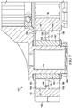
- Multiple roller bearings 196 are disposed between the inner race 182 and the planet gear 172 and the roller bearings are captured between the inner race surface 183 and the outer race surface 186.
- the FDS 200 comprises a substantially cylindrical body 202 and is configured to house a variety of components within the body 202.
- the FDS 200 comprises two light-sensitive charge-coupled device (CCD) camera elements 204 configured to receive light and transmit electrical signals representative of the light received.
- the FDS 200 also comprises an illumination source 206.
- the illumination source 206 comprises a light-emitting diode (LED).
- the FDS 200 comprises a power source 208.
- the power source 208 comprises a battery.
- the FDS 200 further comprises a general-purpose processor system 500.
- Each of the camera elements 204, illumination source 206, and power source 208 are connected to the system 500 using electrical connectors 210 and are controlled by the system 500.
- the body 202 comprises openings and/or windows suitable for allowing the camera elements 204 to receive light.
- the FDS 200 is configured to selectively utilize electrical power from the power source 208 to emit light from the illumination source 206, receive light with the camera elements 204, and to use the system 500 to transmit information about the received light. While FDS 200 is shown as comprising two camera elements 204, each provided so that outer surfaces 205 of the camera elements 204 are generally angled toward different ends of the body 202, other FDSs may only comprise one camera element 204 or may dispose multiple camera elements 204 differently.
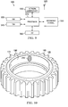
- System 500 that includes a processing component 510 suitable for implementing one or more embodiments disclosed herein.
- the system 500 might include network connectivity devices 520, random access memory (RAM) 530, read only memory (ROM) 540, secondary storage 550, and input/output (I/O) devices 560.
- RAM random access memory
- ROM read only memory
- secondary storage 550 secondary storage
- I/O input/output devices 560.
- some of these components may not be present or may be combined in various combinations with one another or with other components not shown. These components might be located in a single physical entity or in more than one physical entity.
- processor 510 Any actions described herein as being taken by the processor 510 might be taken by the processor 510 alone or by the processor 510 in conjunction with one or more components shown or not shown in the system 500. It will be appreciated that the data described herein can be stored in memory and/or in one or more databases.
- the processor 510 executes instructions, codes, computer programs, or scripts that it might access from the network connectivity devices 520, RAM 530, ROM 540, or secondary storage 550 (which might include various disk-based systems such as hard disk, floppy disk, optical disk, or other drive). While only one processor 510 is shown, multiple processors may be present. Thus, while instructions may be discussed as being executed by processor 510, the instructions may be executed simultaneously, serially, or otherwise by one or multiple processors 510.
- the processor 510 may be implemented as one or more CPU chips and/or application specific integrated chips (ASICs).
- ASICs application specific integrated chips
- the network connectivity devices 520 may take the form of modems, modem banks, Ethernet devices, universal serial bus (USB) interface devices, serial interfaces, token ring devices, fiber distributed data interface (FDDI) devices, wireless local area network (WLAN) devices, radio transceiver devices such as code division multiple access (CDMA) devices, global system for mobile communications (GSM) radio transceiver devices, worldwide interoperability for microwave access (WiMAX) devices, and/or other well-known devices for connecting to networks.
- These network connectivity devices 520 may enable the processor 510 to communicate with the Internet or one or more telecommunications networks or other networks from which the processor 510 might receive information or to which the processor 510 might output information.
- the network connectivity devices 520 might also include one or more transceiver components 525 capable of transmitting and/or receiving data wirelessly in the form of electromagnetic waves, such as radio frequency signals or microwave frequency signals. Alternatively, the data may propagate in or on the surface of electrical conductors, in coaxial cables, in waveguides, in optical media such as optical fiber, or in other media.
- the transceiver component 525 might include separate receiving and transmitting units or a single transceiver.
- Information transmitted or received by the transceiver 525 may include data that has been processed by the processor 510 or instructions that are to be executed by processor 510. Such information may be received from and outputted to a network in the form, for example, of a computer data baseband signal or signal embodied in a carrier wave.
- the data may be ordered according to different sequences as may be desirable for either processing or generating the data or transmitting or receiving the data.
- the baseband signal, the signal embedded in the carrier wave, or other types of signals currently used or hereafter developed may be referred to as the transmission medium and may be generated according to several methods well known to one skilled in the art.
- the RAM 530 might be used to store volatile data and perhaps to store instructions that are executed by the processor 510.
- the ROM 540 is a non-volatile memory device that typically has a smaller memory capacity than the memory capacity of the secondary storage 550. ROM 540 might be used to store instructions and perhaps data that are read during execution of the instructions. Access to both RAM 530 and ROM 540 is typically faster than to secondary storage 550.
- the secondary storage 550 is typically comprised of one or more disk drives or tape drives and might be used for non-volatile storage of data or as an over-flow data storage device if RAM 530 is not large enough to hold all working data. Secondary storage 550 may be used to store programs or instructions that are loaded into RAM 530 when such programs are selected for execution or information is needed.
- the I/O devices 560 may include liquid crystal displays (LCDs), touchscreen displays, keyboards, keypads, switches, dials, mice, track balls, voice recognizers, card readers, paper tape readers, printers, video monitors, transducers, sensors, or other well-known input or output devices.
- the transceiver 525 might be considered to be a component of the I/O devices 560 instead of or in addition to being a component of the network connectivity devices 520. Some or all of the I/O devices 560 may be substantially similar to various components disclosed.
- the FDS 200 can be attached to a portion of the post 174 that remains stationary relative to an associated bearing system 181.
- the FDS 200 is oriented in a manner well-suited for receiving light reflected from the bearing system 181. More specifically, the FDS 200 is oriented so that the camera element 204 located furthest away from post 174 is aimed toward and better suited for receiving light reflecting from the inner race surface 183 while the camera element 204 located nearest the post 174 is aimed toward and better suited for receiving light reflected from the outer race surface 186 (the first track 187).
- the camera element 204 located furthest from the post 174 can nonetheless capture light reflected from a portion of the inner race surface 183 and the roller bearings 196 as they move relative to the FDS 200.
- the camera element 204 located nearer the post 174 is more beneficial in the installation shown since it can capture light reflected from not only the roller bearings 196 but also from potentially all of the outer race surface 186.
- roller bearings 196 pass between the camera element 204 and the outer race surface 186, light reflections from the outer race surface 186 can be obscured or distorted, but with a sufficient number of rotations of the planet gear 172, the camera element 204 is likely to receive light reflected from the entirety of the outer race surface 186 portions that are in line of sight relative to the camera element 204.
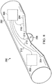
- the damaged planet gear 172' comprises a damaged outer race surface 186'.
- the damage 212 comprises a cracked and/or chipped away portion.
- the damaged outer race surface 186' is able to reflect light to a camera element 204.
- the light is reflected in a more distributed manner so that the light intensity reaching the camera element 204 is less than when an undamaged portion of the outer race surface 186 reflects light to the camera element 204.
- a chart 600 showing two light intensity curves is provided.
- the light intensity curves are plotted against a projection of an uncurled representation of the planet gear 172'.
- the damage 212 is shown as centered at an angular position of 180 degrees.
- an intensity of light received by a camera element 204 increases when a roller bearing 196 is located between the camera element 204 and the outer race surface 186.
- light reflected to the camera element 204 from the damage 212 is relatively less intense than light reelected to the camera element 204 from undamaged portions of the outer race surface 186.
- FDS 200 is not required to construct the curves 602, 604 of chart 600, but rather, the FDS 200 can simply monitor for less than usual light reflection.
- a light intensity differential 606 can be compared to a predetermined differential threshold value so that as the FDS 200 continuously receives reflected light, a visual, audible, or tactile feedback can be generated to indicate that a light reception anomaly has occurred that is approaching, meets, or exceeds the differential threshold value.
- Such an indication may be utilized to indicate a need to discontinue operation of rotorcraft 100 or to otherwise schedule an inspection and/or maintenance of the bearing system 181.
- the failure detection system 700 is substantially similar to FDS 200, but is configured instead or additionally to monitor for chipping or other damage to gear teeth 185. Accordingly, the FDS 700 is further extended from the post 174 to obtain a better optical line of sight of the gear teeth 185.
- the image 800 comprises an image of a known good health or undamaged gear tooth 185, in some cases, provided to the FDS 700 before operation of the rotorcraft 100.
- the image 802 is an image taken of a gear tooth 185 that during or after operation of the rotorcraft 100 has become damaged with a portion chipped away.
- the image 804 comprises a visual representation of how, in some embodiments, the FDS 700 can compare a known good image such as image 800 to a subsequently taken image such as image 802. In some embodiments, the FDS 700 can calculate a percentage optical difference in image field 806 between the content within the image field 806 of image 800 versus the content of the image field 806 of image 804.
- exceeding a threshold percentage difference of image field 806 can trigger one or more of the above described warnings, alerts, and/or actions. Similar image comparison techniques can be used for any other type of component that may be damaged. In this example, the damaged portion 808 is in excess of a threshold amount, so one or more alerts, warnings, and/or actions will be taken in response to the determination that the threshold has been exceeded.
- the general-purpose processor system 500 of FDS 200 may be replaced or supplemented by a field-programmable gate array (FPGA), which is a high-speed logic array, configured to run one or more algorithms for damage detection on the bearing races.
- FPGA field-programmable gate array
- the FDS 200 is configured to take pictures as opposed to simply receiving and reporting light intensity, and the pictures of the race surfaces can be compared to images known to represent undamaged race surfaces and/or to images known to represent damaged race surfaces.
- the FDS 200 can simply compare images taken over a period of time for changes in the image content with the assumption that changes represent damage to the race surfaces.
- data bearing information about a damaged race surface can be relayed wirelessly to a user or to an aircraft health usage monitoring system (HUMS) of the sort commonly known in the art, for subsequent analysis, triggering alarms, and/or otherwise affecting operation of the rotorcraft 100.
- the power source 208 can be receive energy from a battery (as small as a watch battery or even smaller), a slip ring associated with a shaft, or by energy harvesting from rotary motion.
- the FDS 200 can be supplied in very small form factors, it can be utilized with already existing aircraft bearing designs with no bearing modification required.
- the FDS 200 can be disposed within a gearbox housing, such as, but not limited to, gearbox housing 180.
- the type of advance notice of bearing failure the FDS 200 can offer may allow replacement of the damaged bearing systems as opposed to shipping and installing entire gearbox systems or other systems that comprise damaged bearings.
- While the FDS 200 is primarily described above as allowing smart health monitoring of bearings, the same or substantially similar systems can be utilized to optically monitor other machine design components, such as, but not limited to, gears, seals, shafts, and more. In some cases, an entire gearbox could be outfitted with a sufficient number of FDSs 200 to fully monitor each type of machine element and provide real-time failure detection and diagnosis of the system as a whole and each individual monitored component. While such a robust application may not be utilized in the field, a gearbox or transmission may be so fully outfitted when conducting design, development, and/or testing of the large systems. While the FDSs 200 are shown as being adhered to the posts 174, FDSs 200 can alternatively be fastened or otherwise integrated with posts 174 or any other suitable support structure.
- the method 900 can begin at block 902 by providing a FDS, such as, but not limited to, FDS 200, 700.
- the method 900 can progress at block 904 by providing the FDS with a known acceptable optical representation of a part.
- the known acceptable optical representation can be an image (such as a photograph generated by a camera element 204).
- the known acceptable optical representation can comprise a light intensity curve.
- the method 900 can progress at block 906 by operating the FDS to generate an optical representation of the part.
- the method 900 can progress at block 908 by comparing the known acceptable optical representation of the part to the generated optical representation of the part. In some cases, if there exists more than a predetermined threshold amount of difference, an alert, warning, and/or any other suitable action can be taken in response to the threshold amount of difference being met or exceeded.
- R R1 +k * (Ru-Rl), wherein k is a variable ranging from 1 percent to 100 percent with a 1 percent increment, i.e., k is 1 percent, 2 percent, 3 percent, 4 percent, 5 percent,...50 percent, 51 percent, 52 percent,..., 95 percent, 96 percent, 95 percent, 98 percent, 99 percent, or 100 percent.
- R R1 +k * (Ru-Rl)
- k is a variable ranging from 1 percent to 100 percent with a 1 percent increment, i.e., k is 1 percent, 2 percent, 3 percent, 4 percent, 5 percent,...50 percent, 51 percent, 52 percent,..., 95 percent, 96 percent, 95 percent, 98 percent, 99 percent, or 100 percent.
- any numerical range defined by two R numbers as defined in the above is also specifically disclosed.
Landscapes
- Engineering & Computer Science (AREA)
- Mechanical Engineering (AREA)
- General Engineering & Computer Science (AREA)
- Physics & Mathematics (AREA)
- General Physics & Mathematics (AREA)
- Aviation & Aerospace Engineering (AREA)
- Quality & Reliability (AREA)
- Computer Vision & Pattern Recognition (AREA)
- Theoretical Computer Science (AREA)
- Testing Of Devices, Machine Parts, Or Other Structures Thereof (AREA)
Abstract
Description
- Not applicable.
- Not applicable.
- Aircraft such as helicopters commonly comprise power trains, gear trains, planetary gearsets, and/or many other mechanical systems that utilize bearings. The bearings often comprise inner and outer races along which bearing elements roll. The races of bearings can be damaged by fatigue or by exposure to other solids being inadvertently being introduced between the bearing elements and the races of the bearings. Regardless the cause, damaged bearing races can sometimes pose potentially catastrophic failure of larger systems. Conventionally, bearing failure detection is attempted by using chip detectors that monitor for the existence of undesirable pieces of metal. However, chip detectors are not well-suited for providing confirmation as to whether a detected chip is associated with a failing bearing as opposed to any other source of a chip (such as a gear tooth or a machining chip). Accordingly, there is a need for detecting bearing failures as compared to simply indicating an existence of undesirable chip content.
-
-
Figure 1 shows a rotorcraft that comprises a failure detection system (FDS) of this disclosure. -
Figure 2 shows a power train system of the rotorcraft ofFigure 1 . -
Figure 3 shows an isometric view of a rotorcraft gearbox of the power train system ofFigure 2 . -
Figure 4 shows a gear train of the rotorcraft gearbox ofFigure 3 . -
Figure 5 shows a planetary gearset of the gear train ofFigure 4 . -
Figure 6 show a closer view of a planetary gear of the planetary gearset ofFigure 5 . -
Figure 7 shows a cross-sectional view of the planetary gear ofFigure 6 with an associated bearing system. -
Figure 8 shows an oblique view of an FDS in isolation. -
Figure 9 shows a general-purpose processor system of the FDS ofFigure 8 . -
Figure 10 shows an oblique view of a planetary gear that has a surface anomaly. -
Figure 11 is a chart showing a curve of light intensity associated with the planetary gear ofFigure 9 . -
Figure 12 shows an installation of an alternative embodiment of an FDS. -
Figure 13 shows a collection of optical images before and after comparison. -
Figure 14 is a flowchart of a method of detecting part failure. - In the specification, reference may be made to the spatial relationships between various components and to the spatial orientation of various aspects of components as the devices are depicted in the attached drawings. However, as will be recognized by those skilled in the art after a complete reading of the present disclosure, the devices, members, apparatuses, etc. described herein may be positioned in any desired orientation. Thus, the use of terms such as "above," "below," "upper," "lower," or other like terms to describe a spatial relationship between various components or to describe the spatial orientation of aspects of such components should be understood to describe a relative relationship between the components or a spatial orientation of aspects of such components, respectively, as the device described herein may be oriented in any desired direction.
-
Figure 1 shows arotorcraft 100 according to one example embodiment. Rotorcraft 100 featurespower train system 110,main rotor blades 120, tail rotor blades 120', afuselage 130, alanding gear 140, and anempennage 150.Power train system 110 may rotateblades 120 and/or blades 120'.Figure 2 shows thepower train system 110 ofFigure 1 . - In the example of
Figures 1 and 2 ,power train system 110 includes anengine 112, agearbox 160, arotor mast 114, and a tailrotor drive shaft 116.Engine 112 supplies torque tomast 114, viagearbox 160, for rotating ofblades 120.Engine 112 also supplies torque to tailrotor drive shaft 116 for rotating blades 120'. In the examples ofFigures 1 and 2 ,gearbox 160 is a main rotor transmission system. Teachings of certain embodiments recognize, however, thatpower train system 110 may include more or different gearboxes thangearbox 160 shown inFigure 1 .Power train system 110 may include a control system for selectively controlling the pitch of eachblade 120 to selectively control direction, thrust, and lift ofrotorcraft 100. -
Fuselage 130 represents the body ofrotorcraft 100 and may be coupled topower train system 110 such thatpower train system 110 andblades 120 may movefuselage 130 through the air.Landing gear 140 supportsrotorcraft 100 when rotorcraft 100 is landing and/or when rotorcraft 100 is at rest on the ground.Empennage 150 represents the tail section of the aircraft and features blades 120'.Power train system 110 and blades 120' may collectively provide thrust in the same direction as the rotation ofblades 120 to counter the torque effect created byblades 120. It should be appreciated that teachings fromrotorcraft 100 may apply to aircraft other than rotorcraft, such as airplanes, tilt rotors, and unmanned aircraft, to name a few examples. In addition, teachings of certain embodiments relating to rotor systems described herein may apply topower train system 110 and/or other power train systems, including but not limited to non-rotorcraft power train systems. - In the embodiment of
Figures 1 and 2 ,gearbox 160 transmits power from a power source (e.g., engine 112) to an object or objects to be moved (e.g., blades 120). Gearbox 160 converts speed and torque between the power source and the object(s) to be moved. Gearbox 160 may be configured to reduce the speed of the rotational output ofengine 112, while increasing the torque applied toblades 120. -
Figure 3 shows agearbox 160 according to one example embodiment. According to the embodiment ofFigures 3 ,gearbox 160 is a main rotor gearbox and includes arotor mast 114. Gearbox 160 also includes at least onegearbox housing 180 and various gears contained therein (seeFigures 4 and5 ). A gear is a rotating part having teeth that mesh with another toothed part to transmit rotational energy. As one skilled in the art will readily appreciate, the gears withingearbox 160 accomplish speed and torque conversions that are desired for a given implementation. For instance, thegearbox 160 ofFigures 3 reduces rotational speed while multiplying the torque output, which is applied toblades 120 ofrotorcraft 100. -
Figures 4 and5 illustrate agear train 161 contained withingearbox housing 180. Referring to the embodiment ofFigure 4 ,gear train 161 includes aninput pinion 162.Input pinion 162 is in mechanical communication with, and receives rotational energy from, a power source (e.g., engine 112).Input pinion 162 includes a helicalbevel gear portion 163. The helicalbevel gear portion 163 ofinput pinion 162 meshes with, and transmits rotational energy to,bevel gear 164. Bevelgear 164 is a helical bevel gear.Bevel gear 164 meshes with and drives anaccessory drive gear 190, which is configured to provide rotational energy to an accessory gearbox (not shown) and/or various aircraft accessories, such as air blowers, cooling fans, lubrication pumps, hydraulic pumps, electrical generators, and similar components and systems (not shown).Bevel gear 164 is attached via acommon shaft 165 tohelical spur gear 166. Thus,bevel gear 164,common shaft 165, andhelical spur gear 166 rotate together about a common axis. Torque applied tobevel gear 164 is transmitted viacommon shaft 165 tohelical spur gear 166.Helical spur gear 166 meshes with, and transmits rotational energy to,bull gear 167.Bull gear 167 is integral with sun gear 171 (seeFigure 5 ) of planetary gear set 170. Thus, torque applied tobull gear 167 is transmitted tosun gear 171. - The embodiment of
Figure 4 is configured to receive rotational energy from two power sources. Specifically,gear train 161 includes a second input pinion 162', which may be configured to receive rotational energy from a second power source (e.g., a second engine 112). Second input pinion 162' includes a helical bevel gear portion 163'. The helical bevel gear portion 163' of second input pinion 162' meshes with, and transmits rotational energy to, a second bevel gear 164'. Likebevel gear 164, second bevel gear 164' is a helical bevel gear. Second bevel gear 164' meshes with and drives a second accessory drive gear 190', which is configured to provide rotational energy to an accessory gearbox (not shown) and/or various aircraft accessories, such as air blowers, cooling fans, lubrication pumps, hydraulic pumps, electrical generators, and similar components and systems (not shown). Second bevel gear 164' is attached via a second common shaft 165' to a secondhelical spur gear 166'. Thus, second bevel gear 164', second common shaft 165', and secondhelical spur gear 166' rotate together about a common axis. Torque applied to second bevel gear 164' is transmitted via second common shaft 165' to secondhelical spur gear 166'. Secondhelical spur gear 166' meshes with, and transmits rotational energy to,bull gear 167, which is integral with sun gear 171 (seeFigure 5 ). Accordingly, rotational energy provided at either or both input pinions 162, 162' is ultimately combined atbull gear 167 and transmitted tosun gear 171. -
Figure 5 depicts the planetary gear set 170 withingear train 161. Specifically,sun gear 171 is a straight-cut spur gear that meshes with, and transmits rotational energy to, a plurality of planet gears 172. Planet gears 172 are rotatably mounted to aplanetary carrier 173. The embodiment ofFigure 5 includes a total of six planet gears 172. According to the present embodiment,planetary carrier 173 includes a plurality ofposts 174 configured to receive each of the plurality of planet gears 172. Eachpost 174, therefore, defines the rotational axis for acorresponding planet gear 172 rotatably mounted thereon. Theplanetary carrier 173 ofFigures 4 and5 is an overhung planetary carrier, having a plurality of downwardly-extending, cantilevered posts 174. However, one skilled in the art will appreciate that other configurations and orientations are possible for the planetary gear set 170, including theplanetary carrier 173. For instance, in an alternative embodimentplanetary carrier 173 might be a conventional planetary carrier, which one skilled in the art would appreciate as comprising a lower plate, an upper web, and planetary posts extending between the lower plate and upper web. - Referring to
Figure 4 , eachplanet gear 172 also meshes withring gear 175.Ring gear 175 is stationary. According to the present embodiment,ring gear 175 is fixedly mounted withingearbox housing 180 and does rotate with respect to thegearbox housing 180.Planetary carrier 173 establishes the spatial relationship among thesun gear 171, the planet gears 172, and thering gear 175, such that eachplanet gear 172 meshes with both thesun gear 171 and thering gear 175. Because thesun gear 171 rotates while thering gear 175 is fixed, the planet gears 172 travel on an orbiting path aboutsun gear 171 as they rotate onposts 174. This orbiting action causesplanetary carrier 173 to rotate. - According to the embodiment depicted in
Figures 4 and5 , theplanetary carrier 173 includesinternal splines 176.Internal splines 176 mesh with matingexternal splines 118 on rotor mast 114 (seeFigure 4 ). Thus,planetary carrier 173 serves as the main output forgearbox 160 by transmitting rotational energy torotor mast 114. In the embodiment ofFigures 4 and5 , thebull gear 167,sun gear 171,planetary carrier 173, androtor mast 114 all rotate about a substantially common axis of rotation 195 (seeFigure 5 ). - Referring now to
Figures 5-7 eachplanet gear 172 forms a portion of abearing system 181. In this embodiment, the bearingsystems 181 comprise aninner race 182 which is coaxially received on apost 174 and which provides aninner race surface 183. Theinner race 182 is secured in place relative to thepost 174 using aretainer 184 which may be screwed onto thepost 174 or attached using an interference fit. Theplanet gear 172 not only comprisesteeth 185, but also comprises at least oneouter race surface 186. In this embodiment, theouter race surface 186 is shown as comprising afirst track 187 and asecond track 188 separated from thefirst track 187 by adivider wall 189.Multiple roller bearings 196 are disposed between theinner race 182 and theplanet gear 172 and the roller bearings are captured between theinner race surface 183 and theouter race surface 186. - Referring now to
Figure 8 , a failure detection system (FDS) 200 is shown. TheFDS 200 comprises a substantiallycylindrical body 202 and is configured to house a variety of components within thebody 202. In this embodiment, theFDS 200 comprises two light-sensitive charge-coupled device (CCD)camera elements 204 configured to receive light and transmit electrical signals representative of the light received. TheFDS 200 also comprises anillumination source 206. In this embodiment, theillumination source 206 comprises a light-emitting diode (LED). Still further, theFDS 200 comprises apower source 208. In this embodiment, thepower source 208 comprises a battery. TheFDS 200 further comprises a general-purpose processor system 500. Each of thecamera elements 204,illumination source 206, andpower source 208 are connected to thesystem 500 usingelectrical connectors 210 and are controlled by thesystem 500. It will be appreciated that thebody 202 comprises openings and/or windows suitable for allowing thecamera elements 204 to receive light. TheFDS 200 is configured to selectively utilize electrical power from thepower source 208 to emit light from theillumination source 206, receive light with thecamera elements 204, and to use thesystem 500 to transmit information about the received light. WhileFDS 200 is shown as comprising twocamera elements 204, each provided so that outer surfaces 205 of thecamera elements 204 are generally angled toward different ends of thebody 202, other FDSs may only comprise onecamera element 204 or may disposemultiple camera elements 204 differently. - Referring now to
Figure 9 , a simplified diagram of a general-purpose processor (e.g. electronic controller or computer)system 500 suitable for implementing the embodiments of this disclosure is shown.System 500 that includes aprocessing component 510 suitable for implementing one or more embodiments disclosed herein. In addition to the processor 510 (which may be referred to as a central processor unit or CPU), thesystem 500 might includenetwork connectivity devices 520, random access memory (RAM) 530, read only memory (ROM) 540,secondary storage 550, and input/output (I/O)devices 560. In some cases, some of these components may not be present or may be combined in various combinations with one another or with other components not shown. These components might be located in a single physical entity or in more than one physical entity. Any actions described herein as being taken by theprocessor 510 might be taken by theprocessor 510 alone or by theprocessor 510 in conjunction with one or more components shown or not shown in thesystem 500. It will be appreciated that the data described herein can be stored in memory and/or in one or more databases. - The
processor 510 executes instructions, codes, computer programs, or scripts that it might access from thenetwork connectivity devices 520,RAM 530,ROM 540, or secondary storage 550 (which might include various disk-based systems such as hard disk, floppy disk, optical disk, or other drive). While only oneprocessor 510 is shown, multiple processors may be present. Thus, while instructions may be discussed as being executed byprocessor 510, the instructions may be executed simultaneously, serially, or otherwise by one ormultiple processors 510. Theprocessor 510 may be implemented as one or more CPU chips and/or application specific integrated chips (ASICs). - The
network connectivity devices 520 may take the form of modems, modem banks, Ethernet devices, universal serial bus (USB) interface devices, serial interfaces, token ring devices, fiber distributed data interface (FDDI) devices, wireless local area network (WLAN) devices, radio transceiver devices such as code division multiple access (CDMA) devices, global system for mobile communications (GSM) radio transceiver devices, worldwide interoperability for microwave access (WiMAX) devices, and/or other well-known devices for connecting to networks. Thesenetwork connectivity devices 520 may enable theprocessor 510 to communicate with the Internet or one or more telecommunications networks or other networks from which theprocessor 510 might receive information or to which theprocessor 510 might output information. - The
network connectivity devices 520 might also include one ormore transceiver components 525 capable of transmitting and/or receiving data wirelessly in the form of electromagnetic waves, such as radio frequency signals or microwave frequency signals. Alternatively, the data may propagate in or on the surface of electrical conductors, in coaxial cables, in waveguides, in optical media such as optical fiber, or in other media. Thetransceiver component 525 might include separate receiving and transmitting units or a single transceiver. Information transmitted or received by thetransceiver 525 may include data that has been processed by theprocessor 510 or instructions that are to be executed byprocessor 510. Such information may be received from and outputted to a network in the form, for example, of a computer data baseband signal or signal embodied in a carrier wave. The data may be ordered according to different sequences as may be desirable for either processing or generating the data or transmitting or receiving the data. The baseband signal, the signal embedded in the carrier wave, or other types of signals currently used or hereafter developed may be referred to as the transmission medium and may be generated according to several methods well known to one skilled in the art. - The
RAM 530 might be used to store volatile data and perhaps to store instructions that are executed by theprocessor 510. TheROM 540 is a non-volatile memory device that typically has a smaller memory capacity than the memory capacity of thesecondary storage 550.ROM 540 might be used to store instructions and perhaps data that are read during execution of the instructions. Access to bothRAM 530 andROM 540 is typically faster than tosecondary storage 550. Thesecondary storage 550 is typically comprised of one or more disk drives or tape drives and might be used for non-volatile storage of data or as an over-flow data storage device ifRAM 530 is not large enough to hold all working data.Secondary storage 550 may be used to store programs or instructions that are loaded intoRAM 530 when such programs are selected for execution or information is needed. - The I/
O devices 560 may include liquid crystal displays (LCDs), touchscreen displays, keyboards, keypads, switches, dials, mice, track balls, voice recognizers, card readers, paper tape readers, printers, video monitors, transducers, sensors, or other well-known input or output devices. Also, thetransceiver 525 might be considered to be a component of the I/O devices 560 instead of or in addition to being a component of thenetwork connectivity devices 520. Some or all of the I/O devices 560 may be substantially similar to various components disclosed. - As show in
Figures 4-6 , theFDS 200 can be attached to a portion of thepost 174 that remains stationary relative to an associatedbearing system 181. When properly located, with the outer surfaces 205 generally facing theroller bearings 196, theFDS 200 is oriented in a manner well-suited for receiving light reflected from thebearing system 181. More specifically, theFDS 200 is oriented so that thecamera element 204 located furthest away frompost 174 is aimed toward and better suited for receiving light reflecting from theinner race surface 183 while thecamera element 204 located nearest thepost 174 is aimed toward and better suited for receiving light reflected from the outer race surface 186 (the first track 187). While in this embodiment theinner race surface 183 is stationary relative to theFDS 200, thereby preventing theFDS 200 from scanning the entirety of theinner race surface 183, thecamera element 204 located furthest from thepost 174 can nonetheless capture light reflected from a portion of theinner race surface 183 and theroller bearings 196 as they move relative to theFDS 200. Thecamera element 204 located nearer thepost 174 is more beneficial in the installation shown since it can capture light reflected from not only theroller bearings 196 but also from potentially all of theouter race surface 186. Of course, as theroller bearings 196 pass between thecamera element 204 and theouter race surface 186, light reflections from theouter race surface 186 can be obscured or distorted, but with a sufficient number of rotations of theplanet gear 172, thecamera element 204 is likely to receive light reflected from the entirety of theouter race surface 186 portions that are in line of sight relative to thecamera element 204. - Referring now to
Figure 10 , a damaged planet gear 172' is shown. The damaged planet gear 172' comprises a damaged outer race surface 186'. In this embodiment, thedamage 212 comprises a cracked and/or chipped away portion. When the damaged planet gear 172' is installed within abearing system 181 as shown inFigure 6 , the damaged outer race surface 186' is able to reflect light to acamera element 204. However, when light is reflected from thedamage 212, the light is reflected in a more distributed manner so that the light intensity reaching thecamera element 204 is less than when an undamaged portion of theouter race surface 186 reflects light to thecamera element 204. - Referring now to
Figure 11 , achart 600 showing two light intensity curves is provided. The light intensity curves are plotted against a projection of an uncurled representation of the planet gear 172'. For ease of explanation, thedamage 212 is shown as centered at an angular position of 180 degrees. For purposes of this discussion, it is assumed that when theillumination source 206 is active, an intensity of light received by acamera element 204 increases when aroller bearing 196 is located between thecamera element 204 and theouter race surface 186. It is also assumed that when light reflected to thecamera element 204 from thedamage 212 is relatively less intense than light reelected to thecamera element 204 from undamaged portions of theouter race surface 186. Accordingly, if acamera element 204 were to receive reflected light information for the entirety of the outer race surface 186' simultaneously, damaged curve 602 (represented in completely solid line) would result. For comparison, undamaged curve portion 604 (represented in dotted line) would be the result ifdamage 212 did not exist. In some embodiments,FDS 200 is not required to construct thecurves chart 600, but rather, theFDS 200 can simply monitor for less than usual light reflection. For example, a light intensity differential 606 can be compared to a predetermined differential threshold value so that as theFDS 200 continuously receives reflected light, a visual, audible, or tactile feedback can be generated to indicate that a light reception anomaly has occurred that is approaching, meets, or exceeds the differential threshold value. Such an indication may be utilized to indicate a need to discontinue operation ofrotorcraft 100 or to otherwise schedule an inspection and/or maintenance of thebearing system 181. - Referring now to
Figure 12 , a failuredetection system FDS 700 is shown. Thefailure detection system 700 is substantially similar toFDS 200, but is configured instead or additionally to monitor for chipping or other damage to gearteeth 185. Accordingly, theFDS 700 is further extended from thepost 174 to obtain a better optical line of sight of thegear teeth 185. - Referring now to
Figure 13 , a collection images ofgear teeth 185 are shown. Theimage 800 comprises an image of a known good health orundamaged gear tooth 185, in some cases, provided to theFDS 700 before operation of therotorcraft 100. Theimage 802 is an image taken of agear tooth 185 that during or after operation of therotorcraft 100 has become damaged with a portion chipped away. Theimage 804 comprises a visual representation of how, in some embodiments, theFDS 700 can compare a known good image such asimage 800 to a subsequently taken image such asimage 802. In some embodiments, theFDS 700 can calculate a percentage optical difference inimage field 806 between the content within theimage field 806 ofimage 800 versus the content of theimage field 806 ofimage 804. In some cases, exceeding a threshold percentage difference ofimage field 806 can trigger one or more of the above described warnings, alerts, and/or actions. Similar image comparison techniques can be used for any other type of component that may be damaged. In this example, the damagedportion 808 is in excess of a threshold amount, so one or more alerts, warnings, and/or actions will be taken in response to the determination that the threshold has been exceeded. - In an alternative embodiment, the general-
purpose processor system 500 ofFDS 200 may be replaced or supplemented by a field-programmable gate array (FPGA), which is a high-speed logic array, configured to run one or more algorithms for damage detection on the bearing races. In some cases, theFDS 200 is configured to take pictures as opposed to simply receiving and reporting light intensity, and the pictures of the race surfaces can be compared to images known to represent undamaged race surfaces and/or to images known to represent damaged race surfaces. Alternatively, theFDS 200 can simply compare images taken over a period of time for changes in the image content with the assumption that changes represent damage to the race surfaces. In some embodiments, data bearing information about a damaged race surface can be relayed wirelessly to a user or to an aircraft health usage monitoring system (HUMS) of the sort commonly known in the art, for subsequent analysis, triggering alarms, and/or otherwise affecting operation of therotorcraft 100. Thepower source 208 can be receive energy from a battery (as small as a watch battery or even smaller), a slip ring associated with a shaft, or by energy harvesting from rotary motion. Because theFDS 200 can be supplied in very small form factors, it can be utilized with already existing aircraft bearing designs with no bearing modification required. In some embodiments, theFDS 200 can be disposed within a gearbox housing, such as, but not limited to,gearbox housing 180. The type of advance notice of bearing failure theFDS 200 can offer may allow replacement of the damaged bearing systems as opposed to shipping and installing entire gearbox systems or other systems that comprise damaged bearings. - While the
FDS 200 is primarily described above as allowing smart health monitoring of bearings, the same or substantially similar systems can be utilized to optically monitor other machine design components, such as, but not limited to, gears, seals, shafts, and more. In some cases, an entire gearbox could be outfitted with a sufficient number ofFDSs 200 to fully monitor each type of machine element and provide real-time failure detection and diagnosis of the system as a whole and each individual monitored component. While such a robust application may not be utilized in the field, a gearbox or transmission may be so fully outfitted when conducting design, development, and/or testing of the large systems. While theFDSs 200 are shown as being adhered to theposts 174,FDSs 200 can alternatively be fastened or otherwise integrated withposts 174 or any other suitable support structure. - Referring now to
Figure 14 , a method 900 of detecting failure of a part is shown. The method 900 can begin atblock 902 by providing a FDS, such as, but not limited to,FDS block 904 by providing the FDS with a known acceptable optical representation of a part. In some cases, the known acceptable optical representation can be an image (such as a photograph generated by a camera element 204). In other cases, the known acceptable optical representation can comprise a light intensity curve. The method 900 can progress atblock 906 by operating the FDS to generate an optical representation of the part. The method 900 can progress atblock 908 by comparing the known acceptable optical representation of the part to the generated optical representation of the part. In some cases, if there exists more than a predetermined threshold amount of difference, an alert, warning, and/or any other suitable action can be taken in response to the threshold amount of difference being met or exceeded. - At least one embodiment is disclosed, and variations, combinations, and/or modifications of the embodiment(s) and/or features of the embodiment(s) made by a person having ordinary skill in the art are within the scope of this disclosure. Alternative embodiments that result from combining, integrating, and/or omitting features of the embodiment(s) are also within the scope of this disclosure. Where numerical ranges or limitations are expressly stated, such express ranges or limitations should be understood to include iterative ranges or limitations of like magnitude falling within the expressly stated ranges or limitations (e.g., from about 1 to about 10 includes, 2, 3, 4, etc.; greater than 0.10 includes 0.11, 0.12, 0.13, etc.). For example, whenever a numerical range with a lower limit, Rl, and an upper limit, Ru, is disclosed, any number falling within the range is specifically disclosed. In particular, the following numbers within the range are specifically disclosed: R=R1 +k * (Ru-Rl), wherein k is a variable ranging from 1 percent to 100 percent with a 1 percent increment, i.e., k is 1 percent, 2 percent, 3 percent, 4 percent, 5 percent,...50 percent, 51 percent, 52 percent,..., 95 percent, 96 percent, 95 percent, 98 percent, 99 percent, or 100 percent. Moreover, any numerical range defined by two R numbers as defined in the above is also specifically disclosed.
- Use of the term "optionally" with respect to any element of a claim means that the element is required, or alternatively, the element is not required, both alternatives being within the scope of the claim. Use of broader terms such as comprises, includes, and having should be understood to provide support for narrower terms such as consisting of, consisting essentially of, and comprised substantially of. Accordingly, the scope of protection is not limited by the description set out above but is defined by the claims that follow, that scope including all equivalents of the subject matter of the claims. Each and every claim is incorporated as further disclosure into the specification and the claims are embodiment(s) of the present invention. Also, the phrases "at least one of A, B, and C" and "A and/or B and/or C" should each be interpreted to include only A, only B, only C, or any combination of A, B, and C.
Claims (15)
- A failure detection system (FDS) for a gearbox, comprising:a power source disposed within the gearbox;a camera element disposed within the gearbox; anda processor disposed within the gearbox.
- The FDS of claim 1, wherein the power source is a battery.
- The FDS of claim 1 or of claim 2, wherein the camera element comprises a charge-coupled device, and/or wherein the processor comprises a field-programmable gate array.
- The FDS of claim 1 or of claim 2 or of claim 3, further comprising:
an illumination source. - The FDS of claim 1 or of any of claims 2 to 4, wherein the processor comprises a general-purpose processor system; and/or wherein the processor is configured to compare at least two optical representations of a part.
- The FDS of claim 1 or of any of claims 2 to 5, wherein the FDS is attached to a planetary carrier of the gearbox.
- The FDS of claim 1 or of any preceding claim, wherein the processor is configured to wirelessly communicate information regarding an optical representation of a part; and/or wherein the processor is configured to communicate information regarding a comparison of optical representations of a part.
- A method of detecting failure of a part, comprising:disposing a failure detection system (FDS) within a gearbox; andproviding the FDS with a known acceptable optical representation of a part of the gearbox.
- The method of claim 8, further comprising:(i) operating the FDS to generate an optical representation of the part, and optionally or preferably, the method further comprising:(ii) operating the FDS to compare the known acceptable optical representation to the generated optical representation.
- The method of claim 9, part (ii), wherein an action is taken in response to a result of the comparison, and optionally or preferably, wherein an action is taken in response to the comparison resulting in a threshold difference being met or exceeded.
- The method of claim 8 or of any preceding method claim, wherein the known acceptable optical representation of the part comprises a light intensity.
- The method of claim 8 or of any preceding method claim, wherein the known acceptable optical representation of the part comprises a light intensity curve.
- The method of claim 8 or of any preceding method claim, wherein the known acceptable optical representation of the part comprises an image.
- The method of claim 8 or of any preceding method claim, wherein the part comprises a race surface of a bearing.
- The method of claim 8 or of any of claims 9 to 13, wherein the part comprises a gear tooth.
Applications Claiming Priority (1)
| Application Number | Priority Date | Filing Date | Title |
|---|---|---|---|
| US15/916,182 US11043046B2 (en) | 2018-03-08 | 2018-03-08 | Failure detection system |
Publications (2)
| Publication Number | Publication Date |
|---|---|
| EP3536609A1 true EP3536609A1 (en) | 2019-09-11 |
| EP3536609B1 EP3536609B1 (en) | 2022-03-09 |
Family
ID=62152395
Family Applications (1)
| Application Number | Title | Priority Date | Filing Date |
|---|---|---|---|
| EP18171730.7A Active EP3536609B1 (en) | 2018-03-08 | 2018-05-10 | Failure detection system |
Country Status (2)
| Country | Link |
|---|---|
| US (1) | US11043046B2 (en) |
| EP (1) | EP3536609B1 (en) |
Families Citing this family (4)
| Publication number | Priority date | Publication date | Assignee | Title |
|---|---|---|---|---|
| JP2024505079A (en) | 2021-01-28 | 2024-02-02 | オディサイト.エーアイ リミテッド | Systems and methods for monitoring potential failures of machines or machine components |
| US11709113B2 (en) * | 2021-07-08 | 2023-07-25 | Textron Innovations Inc. | Elastomeric bearing monitoring system |
| WO2023209717A1 (en) | 2022-04-27 | 2023-11-02 | Odysight.Ai Ltd | Monitoring a mechanism or a component thereof |
| CN118067622B (en) * | 2024-04-17 | 2024-07-02 | 成都大学 | Optical glass flaw automatic checkout device |
Citations (7)
| Publication number | Priority date | Publication date | Assignee | Title |
|---|---|---|---|---|
| US20090071278A1 (en) * | 2007-09-18 | 2009-03-19 | Hiwin Technologies Corp. | Ball screw device having image sensor |
| DE102008048956A1 (en) * | 2008-09-25 | 2010-04-01 | Repower Systems Ag | Method for monitoring a transmission of a wind energy plant |
| DE102010026085A1 (en) * | 2010-07-05 | 2012-01-05 | Herrenknecht Ag | Method for monitoring at least one gear of a gear in operation |
| US20120025526A1 (en) * | 2010-07-30 | 2012-02-02 | General Electric Company | System and method for monitoring wind turbine gearbox health and performance |
| US20120156034A1 (en) * | 2010-12-17 | 2012-06-21 | Vestas Wind Systems A/S | Apparatus for harvesting energy from a gearbox to power an electrical device and related methods |
| EP2559988A2 (en) * | 2011-08-16 | 2013-02-20 | The Boeing Company | Evaluating the health status of a system |
| US20150116131A1 (en) * | 2012-03-08 | 2015-04-30 | Ntn Corporation | Condition monitoring system |
Family Cites Families (7)
| Publication number | Priority date | Publication date | Assignee | Title |
|---|---|---|---|---|
| US5905923A (en) * | 1998-02-02 | 1999-05-18 | Sensormatic Electronics Corporation | Video camera mounting assembly with friction bearings for inhibiting pan and tilt movements |
| US7912659B2 (en) * | 2004-06-28 | 2011-03-22 | General Electric Company | System and method for monitoring the condition of a drive train |
| US9482647B2 (en) * | 2013-09-24 | 2016-11-01 | Sikorsky Aircraft Corporation | Gear fault detection |
| US9501820B2 (en) * | 2014-01-03 | 2016-11-22 | Bell Helicopter Textron Inc. | Automated nital etch inspection system |
| US9921132B2 (en) * | 2014-01-03 | 2018-03-20 | Bell Helicopter Textron Inc. | Automated magnetic particle and fluorescent penetrant defect detection system |
| US10879757B2 (en) * | 2017-09-07 | 2020-12-29 | Gopro, Inc. | Bearing configuration for an electronic motor |
| US10788394B2 (en) * | 2017-09-12 | 2020-09-29 | General Electric Company | Gearbox sensor arrangement |
-
2018
- 2018-03-08 US US15/916,182 patent/US11043046B2/en active Active
- 2018-05-10 EP EP18171730.7A patent/EP3536609B1/en active Active
Patent Citations (7)
| Publication number | Priority date | Publication date | Assignee | Title |
|---|---|---|---|---|
| US20090071278A1 (en) * | 2007-09-18 | 2009-03-19 | Hiwin Technologies Corp. | Ball screw device having image sensor |
| DE102008048956A1 (en) * | 2008-09-25 | 2010-04-01 | Repower Systems Ag | Method for monitoring a transmission of a wind energy plant |
| DE102010026085A1 (en) * | 2010-07-05 | 2012-01-05 | Herrenknecht Ag | Method for monitoring at least one gear of a gear in operation |
| US20120025526A1 (en) * | 2010-07-30 | 2012-02-02 | General Electric Company | System and method for monitoring wind turbine gearbox health and performance |
| US20120156034A1 (en) * | 2010-12-17 | 2012-06-21 | Vestas Wind Systems A/S | Apparatus for harvesting energy from a gearbox to power an electrical device and related methods |
| EP2559988A2 (en) * | 2011-08-16 | 2013-02-20 | The Boeing Company | Evaluating the health status of a system |
| US20150116131A1 (en) * | 2012-03-08 | 2015-04-30 | Ntn Corporation | Condition monitoring system |
Also Published As
| Publication number | Publication date |
|---|---|
| EP3536609B1 (en) | 2022-03-09 |
| US20190279442A1 (en) | 2019-09-12 |
| US11043046B2 (en) | 2021-06-22 |
Similar Documents
| Publication | Publication Date | Title |
|---|---|---|
| US11043046B2 (en) | Failure detection system | |
| EP2546518B1 (en) | Abrasion detection device, wind power generator equipped therewith, and abrasion detection method | |
| US8393993B2 (en) | Wind turbine comprising at least one gearbox and an epicyclic gearbox | |
| US9765875B2 (en) | Lubrication systems for gearbox assemblies | |
| EP3854680B1 (en) | Rotary-wing aircraft provided with a transmission system equipped with a spare electric motor | |
| KR101938776B1 (en) | Grease Auto- Injection Device and Long Range Radar System having the same | |
| EP3171142A1 (en) | Systems and methods for monitoring gearbox health by vibration | |
| US9683652B2 (en) | Method for the delivery of lubricant to a rotorcraft gearbox | |
| US7708527B2 (en) | Ram air turbine with compound geartrain gearbox | |
| CN105785383A (en) | Laser scanning distance measuring device | |
| CN106019293A (en) | Laser scanning range unit | |
| FR2928020A1 (en) | STRATIFIL WIRELESS SENSOR AND METHOD FOR USE IN A HUMS MONITORING SYSTEM OF A VEHICLE | |
| JP2015063916A (en) | Monitoring system and monitoring method | |
| US10334332B1 (en) | System and method for managing battery life in redundant wireless sensors | |
| US11060606B2 (en) | System and method for locating and charging wireless sensors | |
| US9580187B2 (en) | Rotor index sensor system | |
| CN205643710U (en) | Laser scanning distance measurement device | |
| Trammel et al. | UK Ministry of Defence generic health and usage monitoring system (GenHUMS) | |
| CN115540827A (en) | A submersible marine environment monitoring equipment | |
| US20210016903A1 (en) | Driveshaft Misalignment Measurement Systems and Methods | |
| US10723452B2 (en) | Engine systems for rotorcraft | |
| KR102905431B1 (en) | Underwater centrifugal pump with foreign object removing function | |
| US20250187742A1 (en) | Management of aircraft propulsion imbalance events | |
| FR3152590A1 (en) | Vibration monitoring device for a mechanical power transmission system of an aircraft engine | |
| CN118907468A (en) | Nuclear radiation monitoring system for nuclear pollution area based on unmanned aerial vehicle |
Legal Events
| Date | Code | Title | Description |
|---|---|---|---|
| STAA | Information on the status of an ep patent application or granted ep patent |
Free format text: STATUS: EXAMINATION IS IN PROGRESS |
|
| PUAI | Public reference made under article 153(3) epc to a published international application that has entered the european phase |
Free format text: ORIGINAL CODE: 0009012 |
|
| 17P | Request for examination filed |
Effective date: 20180510 |
|
| AK | Designated contracting states |
Kind code of ref document: A1 Designated state(s): AL AT BE BG CH CY CZ DE DK EE ES FI FR GB GR HR HU IE IS IT LI LT LU LV MC MK MT NL NO PL PT RO RS SE SI SK SM TR |
|
| AX | Request for extension of the european patent |
Extension state: BA ME |
|
| GRAP | Despatch of communication of intention to grant a patent |
Free format text: ORIGINAL CODE: EPIDOSNIGR1 |
|
| STAA | Information on the status of an ep patent application or granted ep patent |
Free format text: STATUS: GRANT OF PATENT IS INTENDED |
|
| INTG | Intention to grant announced |
Effective date: 20210901 |
|
| GRAS | Grant fee paid |
Free format text: ORIGINAL CODE: EPIDOSNIGR3 |
|
| GRAA | (expected) grant |
Free format text: ORIGINAL CODE: 0009210 |
|
| STAA | Information on the status of an ep patent application or granted ep patent |
Free format text: STATUS: THE PATENT HAS BEEN GRANTED |
|
| RAP1 | Party data changed (applicant data changed or rights of an application transferred) |
Owner name: TEXTRON INNOVATIONS INC. |
|
| AK | Designated contracting states |
Kind code of ref document: B1 Designated state(s): AL AT BE BG CH CY CZ DE DK EE ES FI FR GB GR HR HU IE IS IT LI LT LU LV MC MK MT NL NO PL PT RO RS SE SI SK SM TR |
|
| REG | Reference to a national code |
Ref country code: CH Ref legal event code: EP Ref country code: AT Ref legal event code: REF Ref document number: 1473951 Country of ref document: AT Kind code of ref document: T Effective date: 20220315 |
|
| REG | Reference to a national code |
Ref country code: DE Ref legal event code: R096 Ref document number: 602018031854 Country of ref document: DE |
|
| REG | Reference to a national code |
Ref country code: IE Ref legal event code: FG4D |
|
| REG | Reference to a national code |
Ref country code: LT Ref legal event code: MG9D |
|
| REG | Reference to a national code |
Ref country code: NL Ref legal event code: MP Effective date: 20220309 |
|
| PG25 | Lapsed in a contracting state [announced via postgrant information from national office to epo] |
Ref country code: SE Free format text: LAPSE BECAUSE OF FAILURE TO SUBMIT A TRANSLATION OF THE DESCRIPTION OR TO PAY THE FEE WITHIN THE PRESCRIBED TIME-LIMIT Effective date: 20220309 Ref country code: RS Free format text: LAPSE BECAUSE OF FAILURE TO SUBMIT A TRANSLATION OF THE DESCRIPTION OR TO PAY THE FEE WITHIN THE PRESCRIBED TIME-LIMIT Effective date: 20220309 Ref country code: NO Free format text: LAPSE BECAUSE OF FAILURE TO SUBMIT A TRANSLATION OF THE DESCRIPTION OR TO PAY THE FEE WITHIN THE PRESCRIBED TIME-LIMIT Effective date: 20220609 Ref country code: LT Free format text: LAPSE BECAUSE OF FAILURE TO SUBMIT A TRANSLATION OF THE DESCRIPTION OR TO PAY THE FEE WITHIN THE PRESCRIBED TIME-LIMIT Effective date: 20220309 Ref country code: HR Free format text: LAPSE BECAUSE OF FAILURE TO SUBMIT A TRANSLATION OF THE DESCRIPTION OR TO PAY THE FEE WITHIN THE PRESCRIBED TIME-LIMIT Effective date: 20220309 Ref country code: BG Free format text: LAPSE BECAUSE OF FAILURE TO SUBMIT A TRANSLATION OF THE DESCRIPTION OR TO PAY THE FEE WITHIN THE PRESCRIBED TIME-LIMIT Effective date: 20220609 |
|
| REG | Reference to a national code |
Ref country code: AT Ref legal event code: MK05 Ref document number: 1473951 Country of ref document: AT Kind code of ref document: T Effective date: 20220309 |
|
| PG25 | Lapsed in a contracting state [announced via postgrant information from national office to epo] |
Ref country code: LV Free format text: LAPSE BECAUSE OF FAILURE TO SUBMIT A TRANSLATION OF THE DESCRIPTION OR TO PAY THE FEE WITHIN THE PRESCRIBED TIME-LIMIT Effective date: 20220309 Ref country code: GR Free format text: LAPSE BECAUSE OF FAILURE TO SUBMIT A TRANSLATION OF THE DESCRIPTION OR TO PAY THE FEE WITHIN THE PRESCRIBED TIME-LIMIT Effective date: 20220610 Ref country code: FI Free format text: LAPSE BECAUSE OF FAILURE TO SUBMIT A TRANSLATION OF THE DESCRIPTION OR TO PAY THE FEE WITHIN THE PRESCRIBED TIME-LIMIT Effective date: 20220309 |
|
| PG25 | Lapsed in a contracting state [announced via postgrant information from national office to epo] |
Ref country code: NL Free format text: LAPSE BECAUSE OF FAILURE TO SUBMIT A TRANSLATION OF THE DESCRIPTION OR TO PAY THE FEE WITHIN THE PRESCRIBED TIME-LIMIT Effective date: 20220309 |
|
| PG25 | Lapsed in a contracting state [announced via postgrant information from national office to epo] |
Ref country code: SM Free format text: LAPSE BECAUSE OF FAILURE TO SUBMIT A TRANSLATION OF THE DESCRIPTION OR TO PAY THE FEE WITHIN THE PRESCRIBED TIME-LIMIT Effective date: 20220309 Ref country code: SK Free format text: LAPSE BECAUSE OF FAILURE TO SUBMIT A TRANSLATION OF THE DESCRIPTION OR TO PAY THE FEE WITHIN THE PRESCRIBED TIME-LIMIT Effective date: 20220309 Ref country code: RO Free format text: LAPSE BECAUSE OF FAILURE TO SUBMIT A TRANSLATION OF THE DESCRIPTION OR TO PAY THE FEE WITHIN THE PRESCRIBED TIME-LIMIT Effective date: 20220309 Ref country code: PT Free format text: LAPSE BECAUSE OF FAILURE TO SUBMIT A TRANSLATION OF THE DESCRIPTION OR TO PAY THE FEE WITHIN THE PRESCRIBED TIME-LIMIT Effective date: 20220711 Ref country code: ES Free format text: LAPSE BECAUSE OF FAILURE TO SUBMIT A TRANSLATION OF THE DESCRIPTION OR TO PAY THE FEE WITHIN THE PRESCRIBED TIME-LIMIT Effective date: 20220309 Ref country code: EE Free format text: LAPSE BECAUSE OF FAILURE TO SUBMIT A TRANSLATION OF THE DESCRIPTION OR TO PAY THE FEE WITHIN THE PRESCRIBED TIME-LIMIT Effective date: 20220309 Ref country code: CZ Free format text: LAPSE BECAUSE OF FAILURE TO SUBMIT A TRANSLATION OF THE DESCRIPTION OR TO PAY THE FEE WITHIN THE PRESCRIBED TIME-LIMIT Effective date: 20220309 Ref country code: AT Free format text: LAPSE BECAUSE OF FAILURE TO SUBMIT A TRANSLATION OF THE DESCRIPTION OR TO PAY THE FEE WITHIN THE PRESCRIBED TIME-LIMIT Effective date: 20220309 |
|
| PG25 | Lapsed in a contracting state [announced via postgrant information from national office to epo] |
Ref country code: PL Free format text: LAPSE BECAUSE OF FAILURE TO SUBMIT A TRANSLATION OF THE DESCRIPTION OR TO PAY THE FEE WITHIN THE PRESCRIBED TIME-LIMIT Effective date: 20220309 Ref country code: IS Free format text: LAPSE BECAUSE OF FAILURE TO SUBMIT A TRANSLATION OF THE DESCRIPTION OR TO PAY THE FEE WITHIN THE PRESCRIBED TIME-LIMIT Effective date: 20220709 Ref country code: AL Free format text: LAPSE BECAUSE OF FAILURE TO SUBMIT A TRANSLATION OF THE DESCRIPTION OR TO PAY THE FEE WITHIN THE PRESCRIBED TIME-LIMIT Effective date: 20220309 |
|
| REG | Reference to a national code |
Ref country code: DE Ref legal event code: R097 Ref document number: 602018031854 Country of ref document: DE |
|
| REG | Reference to a national code |
Ref country code: CH Ref legal event code: PL |
|
| PLBE | No opposition filed within time limit |
Free format text: ORIGINAL CODE: 0009261 |
|
| STAA | Information on the status of an ep patent application or granted ep patent |
Free format text: STATUS: NO OPPOSITION FILED WITHIN TIME LIMIT |
|
| REG | Reference to a national code |
Ref country code: BE Ref legal event code: MM Effective date: 20220531 |
|
| PG25 | Lapsed in a contracting state [announced via postgrant information from national office to epo] |
Ref country code: MC Free format text: LAPSE BECAUSE OF FAILURE TO SUBMIT A TRANSLATION OF THE DESCRIPTION OR TO PAY THE FEE WITHIN THE PRESCRIBED TIME-LIMIT Effective date: 20220309 Ref country code: LU Free format text: LAPSE BECAUSE OF NON-PAYMENT OF DUE FEES Effective date: 20220510 Ref country code: LI Free format text: LAPSE BECAUSE OF NON-PAYMENT OF DUE FEES Effective date: 20220531 Ref country code: DK Free format text: LAPSE BECAUSE OF FAILURE TO SUBMIT A TRANSLATION OF THE DESCRIPTION OR TO PAY THE FEE WITHIN THE PRESCRIBED TIME-LIMIT Effective date: 20220309 Ref country code: CH Free format text: LAPSE BECAUSE OF NON-PAYMENT OF DUE FEES Effective date: 20220531 |
|
| 26N | No opposition filed |
Effective date: 20221212 |
|
| PG25 | Lapsed in a contracting state [announced via postgrant information from national office to epo] |
Ref country code: SI Free format text: LAPSE BECAUSE OF FAILURE TO SUBMIT A TRANSLATION OF THE DESCRIPTION OR TO PAY THE FEE WITHIN THE PRESCRIBED TIME-LIMIT Effective date: 20220309 |
|
| PG25 | Lapsed in a contracting state [announced via postgrant information from national office to epo] |
Ref country code: IE Free format text: LAPSE BECAUSE OF NON-PAYMENT OF DUE FEES Effective date: 20220510 |
|
| PG25 | Lapsed in a contracting state [announced via postgrant information from national office to epo] |
Ref country code: BE Free format text: LAPSE BECAUSE OF NON-PAYMENT OF DUE FEES Effective date: 20220531 |
|
| P01 | Opt-out of the competence of the unified patent court (upc) registered |
Effective date: 20230602 |
|
| PG25 | Lapsed in a contracting state [announced via postgrant information from national office to epo] |
Ref country code: HU Free format text: LAPSE BECAUSE OF FAILURE TO SUBMIT A TRANSLATION OF THE DESCRIPTION OR TO PAY THE FEE WITHIN THE PRESCRIBED TIME-LIMIT; INVALID AB INITIO Effective date: 20180510 |
|
| PG25 | Lapsed in a contracting state [announced via postgrant information from national office to epo] |
Ref country code: MK Free format text: LAPSE BECAUSE OF FAILURE TO SUBMIT A TRANSLATION OF THE DESCRIPTION OR TO PAY THE FEE WITHIN THE PRESCRIBED TIME-LIMIT Effective date: 20220309 Ref country code: CY Free format text: LAPSE BECAUSE OF FAILURE TO SUBMIT A TRANSLATION OF THE DESCRIPTION OR TO PAY THE FEE WITHIN THE PRESCRIBED TIME-LIMIT Effective date: 20220309 |
|
| PG25 | Lapsed in a contracting state [announced via postgrant information from national office to epo] |
Ref country code: MT Free format text: LAPSE BECAUSE OF FAILURE TO SUBMIT A TRANSLATION OF THE DESCRIPTION OR TO PAY THE FEE WITHIN THE PRESCRIBED TIME-LIMIT Effective date: 20220309 |
|
| PG25 | Lapsed in a contracting state [announced via postgrant information from national office to epo] |
Ref country code: TR Free format text: LAPSE BECAUSE OF FAILURE TO SUBMIT A TRANSLATION OF THE DESCRIPTION OR TO PAY THE FEE WITHIN THE PRESCRIBED TIME-LIMIT Effective date: 20220309 |
|
| PGFP | Annual fee paid to national office [announced via postgrant information from national office to epo] |
Ref country code: GB Payment date: 20260527 Year of fee payment: 9 |
|
| PGFP | Annual fee paid to national office [announced via postgrant information from national office to epo] |
Ref country code: IT Payment date: 20260520 Year of fee payment: 9 |
|
| PGFP | Annual fee paid to national office [announced via postgrant information from national office to epo] |
Ref country code: DE Payment date: 20260528 Year of fee payment: 9 |
|
| PGFP | Annual fee paid to national office [announced via postgrant information from national office to epo] |
Ref country code: FR Payment date: 20260525 Year of fee payment: 9 |