EP3536601B1 - Lateral guide, lateral guide group, freight deck, aircraft - Google Patents
Lateral guide, lateral guide group, freight deck, aircraft Download PDFInfo
- Publication number
- EP3536601B1 EP3536601B1 EP19160774.6A EP19160774A EP3536601B1 EP 3536601 B1 EP3536601 B1 EP 3536601B1 EP 19160774 A EP19160774 A EP 19160774A EP 3536601 B1 EP3536601 B1 EP 3536601B1
- Authority
- EP
- European Patent Office
- Prior art keywords
- lateral guide
- fastening
- rail
- aircraft
- lateral
- Prior art date
- Legal status (The legal status is an assumption and is not a legal conclusion. Google has not performed a legal analysis and makes no representation as to the accuracy of the status listed.)
- Active
Links
- 210000000078 claw Anatomy 0.000 claims description 22
- 238000003780 insertion Methods 0.000 claims description 5
- 230000037431 insertion Effects 0.000 claims description 5
- 238000010008 shearing Methods 0.000 claims 1
- 238000006243 chemical reaction Methods 0.000 description 4
- 238000006073 displacement reaction Methods 0.000 description 3
- 230000002950 deficient Effects 0.000 description 2
- 230000007704 transition Effects 0.000 description 2
- 230000001154 acute effect Effects 0.000 description 1
- 230000000903 blocking effect Effects 0.000 description 1
- 230000001419 dependent effect Effects 0.000 description 1
- 238000005553 drilling Methods 0.000 description 1
- 239000000428 dust Substances 0.000 description 1
- 238000005516 engineering process Methods 0.000 description 1
- 239000000314 lubricant Substances 0.000 description 1
- 238000012423 maintenance Methods 0.000 description 1
- 238000004519 manufacturing process Methods 0.000 description 1
- 239000000463 material Substances 0.000 description 1
- 238000009420 retrofitting Methods 0.000 description 1
Images


Classifications
-
- B—PERFORMING OPERATIONS; TRANSPORTING
- B64—AIRCRAFT; AVIATION; COSMONAUTICS
- B64D—EQUIPMENT FOR FITTING IN OR TO AIRCRAFT; FLIGHT SUITS; PARACHUTES; ARRANGEMENTS OR MOUNTING OF POWER PLANTS OR PROPULSION TRANSMISSIONS IN AIRCRAFT
- B64D9/00—Equipment for handling freight; Equipment for facilitating passenger embarkation or the like
- B64D9/003—Devices for retaining pallets or freight containers
-
- B—PERFORMING OPERATIONS; TRANSPORTING
- B64—AIRCRAFT; AVIATION; COSMONAUTICS
- B64C—AEROPLANES; HELICOPTERS
- B64C1/00—Fuselages; Constructional features common to fuselages, wings, stabilising surfaces or the like
- B64C1/18—Floors
- B64C1/20—Floors specially adapted for freight
-
- B—PERFORMING OPERATIONS; TRANSPORTING
- B64—AIRCRAFT; AVIATION; COSMONAUTICS
- B64C—AEROPLANES; HELICOPTERS
- B64C2211/00—Modular constructions of airplanes or helicopters
-
- B—PERFORMING OPERATIONS; TRANSPORTING
- B64—AIRCRAFT; AVIATION; COSMONAUTICS
- B64D—EQUIPMENT FOR FITTING IN OR TO AIRCRAFT; FLIGHT SUITS; PARACHUTES; ARRANGEMENTS OR MOUNTING OF POWER PLANTS OR PROPULSION TRANSMISSIONS IN AIRCRAFT
- B64D9/00—Equipment for handling freight; Equipment for facilitating passenger embarkation or the like
- B64D2009/006—Rollers or drives for pallets of freight containers, e.g. PDU
Definitions
- the invention relates to a lateral guide for guiding freight items, a lateral guide group with a multiplicity of corresponding lateral guides and a cargo deck or aircraft equipped with a corresponding lateral guide or lateral guide group.
- Pallets measuring 243.8 by 497.8 cm (96 x 196 inches) or 243.8 by 605.8 cm (96 x 238.5 inches), for example, are used for particularly large freight items.
- the latter are also referred to as 16ft or 20ft pallets and are based on the standard sizes of ISO668 (intermodal) containers for sea freight or truck freight.
- ISO668 intermodal containers for sea freight or truck freight.
- To hold and guide such standardized cargo are mounted on the cargo deck side rails used.
- Suitable side guides must be able to be attached and reconfigured quickly and easily, since the costs for operating the corresponding aircraft are very high.
- the configuration should be very easy to carry out, since the personnel who carry out these reconfigurations have often had no or only poor training for the cargo decks used.
- the side guides have to be very robust, since they are exposed to very high loads and careful handling cannot be required due to the high time pressure when loading and unloading.
- a cargo deck with corresponding side rails is often exposed to moisture, high temperature differences, dust and other harsh influences.
- a defective cargo deck - even a defective functional element (roller, guide, bolt, claw) of the cargo deck - can mean that the parking space cannot be used, or in the worst case the aircraft in question cannot be used for several days. Such a failure is very expensive.
- the equipment on the cargo deck of an aircraft is clearly noticeable in the total weight of the aircraft, so that it is desirable to save weight here.
- Lateral guides in aircraft are usually used to guide freight items in the longitudinal direction (x-direction) of the aircraft (from nose to tail, or from tail to nose). During the flight, they absorb forces transverse (y and z direction) to the longitudinal direction and hold the freight items in their position.
- the lateral guide device which performs the actual guiding and holding function of the lateral guide, is slidably mounted in a fastening frame.
- the lateral guide device can therefore assume different positions in order to hold and guide freight items with different dimensions.
- numerous lateral guide devices that have to be arranged at different positions within the cargo deck can be saved.
- the at least one lateral guide device can preferably be displaced along the fastening rail.
- the first fastening device encompasses the fastening rail and/or engages in the fastening rail in such a way that the first fastening device can also be displaced in the longitudinal direction.
- the fastening device can be a fastening base, for example, which engages in corresponding perforated rails with corresponding pins or strips for fixing the fastening rail on the cargo deck.
- the displaceability of the first fastening device has various advantages. On the one hand, side guides that are equipped with corresponding sliding fastening devices can be mounted more easily on the cargo deck. Furthermore, appropriately equipped lateral guides can be used in a large number of places. For example, the cargo hold can be narrowed in the rear of the aircraft, so that other perforated rail distances are specified. Due to the displaceability of the first fastening device, the same side guide can also be used there.
- corresponding lateral guides can be manufactured industrially and used for a large number of different aircraft.
- a fastening rail instead of a fastening frame or a U-profile has the further advantage that a highly functional lateral guide can be provided with a very low weight. It is also possible, due to the use of the fastening rail, to reduce the structural height of the lateral guide, at least in the area free of the guide device.
- the mounting rail has a cross-section of an I-beam.
- the upper section of the T-beam can be used to create a form fit with the at least one lateral guide device.
- the lower section of the T-bar can form a corresponding form fit with one or more fastening devices.
- the individual T-beams of the double T-beam therefore help to efficiently introduce tensile loads (z-direction) into the structure of the aircraft. Furthermore, this shape makes it possible to ensure the displaceability of the fastening devices and the at least one lateral guide device.
- the I-beam cross section can also be defined as an X cross section.
- the crossbeams of the individual T-beams do not necessarily have to run parallel to one another over the entire length, but can have a certain inclination, in particular in the middle.
- At least one of the fastening devices is fastened to the fastening rail via a form fit with (lateral) play in such a way that the fastening rail can be rotated from a basic position relative to the fastening device.
- the ability to rotate can be designed in such a way that a rotation of at least 10° or at least 20° is possible in relation to the basic position. This rotation can take place both in the plus and in the minus direction.
- the basic position can be defined in such a way that the fastening device runs essentially transversely to the fastening rail. If the fastening device snaps into a perforated rail, the perforated rail forms a right angle with the fastening rail in the basic position.
- the game when engaging in the mounting rail allows twisting relative to this basic position.
- the degrees of freedom achieved in this way can be used to anchor the lateral guide according to the invention also in perforated rails or perforated rail segments that do not run in the longitudinal direction of the aircraft.
- the cargo space narrows in the rear area, so that perforated rails running at an angle can be provided here accordingly.
- At least one lateral guide device in such a way that it can be removed upwards (z-direction) and fixed in a different position.
- a positive connection to the fastening rail is produced in at least one lateral guide device, so that the fastening rail can only be displaced in the longitudinal direction.
- the at least one lateral guide device encompasses the fastening rail and has the cross section of a C-profile in the lower area.
- the lateral guide device can nevertheless be replaced by pushing the lateral guide device beyond one of the ends of the fastening rail. In this way, simple maintenance or simple replacement of the lateral guide devices can be guaranteed.
- fastening rails can be equipped with different lateral guide devices in order to be able to offer different configurations.
- the lateral guide has at least one guide roller, which is mounted in the fastening rail so that it can rotate about an axis of rotation.
- the axis of rotation runs essentially parallel to the longitudinal direction of the fastening rail, so that freight items can be transported or guided transversely to the fastening rail.
- the fastening rail has, in a preferred embodiment, a recess which is open towards the top, for example in the form of a V-profile.
- the housing of the guide roller can have a corresponding shape, in particular a V shape.
- the guide roller or the axis of the guide roller can be connected to the lateral guide device or not.
- a/the housing of the guide roller is an integral part of the lateral guide device.
- the lateral guide therefore has at least one guide roller, which facilitates the transport of the freight items. Like the lateral guide device, this guide roller therefore assumes different positions. A large number of guide rollers can be saved as a result of the movable mounting of the guide roller. Furthermore, a modern cargo deck is so densely populated with functional elements (e.g. side guides, guide rollers, locking claws, PDUs) that it is often difficult to find the right place for the necessary functional elements on the cargo deck. Due to the targeted saving of guide rollers and lateral guide devices according to the invention, a cargo deck can be produced that enables an even greater number of different configurations.
- functional elements e.g. side guides, guide rollers, locking claws, PDUs
- the lateral guide can include at least one fixing device for fixing the lateral guide device in at least two different positions on the fastening rail. It is possible to configure the lateral guide according to the invention in such a way that it can be moved in an area in which it performs the function of a stop to protect the structure of the aircraft during loading and unloading. This function is used especially in the cargo door area, e.g. the upper cargo deck, when cargo items, e.g. containers and/or pallets, which are longer than the cargo door are wide, are to be loaded by "turning in”. In this case, the lateral guide devices are pushed outwards as far as possible in relation to the cargo door—close to the outer skin of the aircraft—in order to obtain the largest possible turning range.
- the cargo door area e.g. the upper cargo deck
- the fixing device can include latching elements and counter-latching elements at defined positions on the fastening rail.
- latching elements and counter-latching elements enable the lateral guide devices to assume predefined positions. These positions can be selected in such a way that freight items with specified standard dimensions can be carried. In this respect, these latching and counter-latching elements make it easier to assume a certain predetermined configuration.
- the fixing device can include at least one fixing pin, which is inserted through holes in the mounting rail. In one embodiment, run these holes in the arranged state of the lateral guide in the longitudinal direction of the aircraft - that is, transverse to the longitudinal direction of the mounting rail.
- the fixation pin can be a ball-locking pin, which engages during insertion, so that the fixation pin is prevented from slipping out, for example due to vibrations.
- the lock can be released by means of a button provided on the head of the pin, so that the fixing pin can be easily removed.
- At least one cornering device is lockable in a position relatively near the end of the mounting rail.
- sticking can occur within 5 cm of the end of the mounting rail.
- the fastening rail can have a maximum width of 10 cm, in particular a maximum of 8 cm. In one embodiment, the mounting rail is only about 6 cm wide.
- the fastening rail can have a fastening length of at least 15, 20, 30 or 50 cm. Longer versions (e.g. 1 m to 1.5 m) are also conceivable. In this case, the fastening rail spans at least two, preferably three or more perforated rails. In such cases, the fastening rail is fastened to each crossed or spanned perforated rail using the necessary number of fastening devices.
- the fastening rail is therefore relatively long, so that the fastening points, in which the fastening devices are attached, can be relatively far apart. Although this means that the mounting rail is heavier due to the length. On the other hand, when converting an aircraft, there is no need to provide additional perforated rails or seat rails for the lateral guide, which means that weight can be saved to a considerable extent. In one embodiment, perforated rails are only provided where longitudinal beams are located for fastening the lateral guide.
- One of the lateral guide devices can include a stop and/or a locking claw which is fastened to the fastening rail in such a way that the stop or locking claw can be pivoted from a raised working position into a lowered rest position.
- the stop or the locking claw on the lateral guide device can assume different functional positions in order to guide and hold the freight items in them.
- the stop or the locking claw can be lowered so that freight items can drive over them. This means that further configurations of the cargo deck can be guaranteed.
- a cargo deck can be created that can be flexibly adapted to lock different sizes of cargo. It is also possible to create a cargo deck that does not have any (overhanging) side rails and can be covered with one or more panels, e.g. for loading a vehicle.
- the lateral guide has two lateral guide devices, the internal lateral guide device being pivotable between the working position and the rest position.
- the lateral guide device can be fastened to the fastening rail so that it can rotate about a pivot axis.
- the stop or the locking claw on the lateral guide device can have inclined surfaces on at least one side in order to move them from the working position to the rest position when a piece of freight runs over them from the side.
- the lateral guidance device can comprise at least one locking claw for at least partially encompassing the freight items.
- the locking claw can be resiliently attached to the mounting rail. In this respect, it is possible to absorb forces acting on the locking claw in a resilient manner and to divert them into the cargo deck via the fastening rail.
- At least one fastening device is equipped in such a way that it can be introduced at an angle into a perforated rail and anchored there by being lowered into the horizontal plane.
- the first or second fastening device have a strip for inserting the fastening device into the respective perforated rail along an insertion direction and at least one pin opposite the strip for securing the fastening device against displacement transversely to the insertion direction.
- the respective fastening device is preferably designed in such a way that the opposite pin sits in a hole in the perforated rail when the lateral guide is in the arranged state.
- At least two of these pins are provided opposite to the bar, so that forces acting in the transverse direction can be efficiently passed on to the corresponding perforated rail.
- a lateral guide group comprising a large number of lateral guides as already described, the lateral guide devices of the individual lateral guides having at least one common profile rail which is slidably fastened to the fastening rail.
- the rail can be rigidly or detachably connected to the individual side guide devices and guide the freight items.
- the rail may have locking claws, preferably of different types. Since the freight items differ not only in their transverse dimensions but also in their longitudinal dimensions, it is advantageous if the rail extends over longer sections.
- suitable functional elements in particular locking claws, can be provided in such a way that a suitable holder is available for each piece of freight.
- the locking claws can be arranged directly above a corresponding fastening frame or offset in relation thereto. It is therefore possible to choose the position of the functional elements in the longitudinal direction of the aircraft independently of the position of the fastening rails.
- a rail can accommodate a large number of different locking claws, which are preferably arranged on it at different distances.
- a corresponding lateral guide group is particularly advantageous in the loading and unloading area, since the freight sometimes enters the cargo hold at an angle here.
- the object is achieved by a cargo loading deck with at least one of the lateral guide groups described and/or with at least one of the lateral guides described.
- the aircraft is equipped with at least one side guide.
- the lateral guide can be one of the lateral guides as already described above.
- the lateral guide can comprise a fastening rail extending in the transverse direction of the aircraft and at least one lateral guide device which can be fastened at different positions on the fastening rail.
- the fastening rail can be connected to some of the supporting structure elements of the aircraft via a first fastening point and a second fastening point, with the first fastening point being able to be located above one of the side profiles and the second fastening point being situated above one of the cross members.
- the attachment point can be understood as the point or the region in which tensile forces (z-direction) acting on the lateral guide are mainly introduced into the supporting structure of the aircraft. If screws are used for attachment, the attachment point is essentially the region in which the screw engages in the supporting structure elements. Insofar as adapters that engage in seat rails are used as fastening devices, the fastening point is the region that the corresponding adapter defines. The fact that an attachment point is above an element, for example above the side profile, does not necessarily mean that the attachment cannot take place within this element.
- the solution according to the invention described has the advantage that in the side areas of the cargo deck where there is a relatively large distance between the side profiles and the crossbeams, no additional seat rails that are not (immediately) located above crossbeams have to be drawn in.
- Weight can be saved by dispensing with corresponding seat rails or perforated rails.
- a distance of more than 15 cm, in particular more than 20 cm, can be provided between the first and the second or next attachment point.
- the first attachment point is preferably provided relatively close to the outer skin of the aircraft.
- the shortest distance between the aircraft skin and the first attachment point is less than or equal to 30 cm. Embodiments are also possible in which this maximum distance is less than 25 or less than 20 cm.
- the fastening rail is fastened to the side profile at the first fastening point via a fitting. Additionally or alternatively, the fastening rail can be fastened at the second fastening point to a perforated rail mounted on the cross member.
- Using a fitting allows easy retrofitting of an attachment point. Furthermore, by using a fitting with a (short) perforated rail segment, considerable weight can be saved compared to a perforated rail.
- At least one lateral guide is arranged in the area of the wing center box ("wing box").
- wing box An arrangement in this area requires a particularly high degree of flexibility, since significant deformations can occur in these areas due to the presence of the wings.
- said lateral guide can be connected to a carriage at a/the first attachment point, the carriage being movably seated in the transverse direction of the aircraft on a projection which is connected to one of the frames and/or the wing center box. Due to the arrangement, it is possible that a deformation of the frames does not affect the function of the side rails and the cargo deck. The required deformability is guaranteed. The resulting forces are introduced directly (via the frame) or directly into the center wing box.
- the carriage can have a receptacle which extends in the transverse direction of the aircraft and into which the projection engages in a form-fitting manner.
- the recording preferably runs in the transverse direction of the aircraft.
- the receptacle may have a lubricant and/or an inner lining of lubricious material, e.g.
- a Cartesian coordinate system is usually used to provide individual directional information within an aircraft.
- the x-axis extends from the stern to the bow, the y-axis runs transversely to the x-axis and lies essentially in the plane spanned by the wings.
- the z-axis is perpendicular to the x- and y-axes.
- FIGS. 1 and 2 show an upper cargo deck (compare 21 ).
- a large number of circular frames 105, 105', 105", 105′′′ can be seen, on the outside of which the aircraft outer skin 101 is arranged.
- the frames 105, 105', 105", 105′′′ together with the aircraft outer skin 101 form the fuselage of the aircraft.
- crossbeams 111, 111' run along the y-axis of the aircraft.
- the ends of the cross members 111, 111' are each attached to one of the frames 105, 105', 105", so that the fuselage is stiffened.
- the upper side of the cross members 111 define a plane (xy plane) on which the longitudinal members 112 are preferably arranged at equal distances, for example from about 50 to 70 cm.
- each side of the upper cargo deck 110 In the immediate vicinity of the frames 105, 105', 105" runs on each side of the upper cargo deck 110 - parallel to the longitudinal members 112 - a side profile, for example the Z-profile 118.
- This Z-profile 118 runs parallel to the longitudinal members 112 and is connected to shear beams 107, 107', which are attached directly to the aircraft outer skin 101.
- the shear beams 107, 107' each run between two frames 105, 105', 105'' at an acute angle towards the Z-profile 118.
- the shear beams 107, 107' stiffen the network of longitudinal beams 112 and transverse beams 111, 111' in such a way that the upper cargo deck 110 can absorb shear forces to a considerable extent.
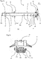
- Lateral guides 10, 10', 10" designed according to the invention are arranged on the described support structure elements.
- the lateral guides 10, 10' are each attached at two attachment points P1, P2 (cf. 4 ) connected to the structure elements.
- the first attachment point P1 sits above the Z-profile 118, the second attachment point P2 above the longitudinal member 112 on which a perforated rail 114 is mounted.
- the lateral guide 10 thus bridges the gap between the Z profile 118 and the longitudinal member 112, with the fastening rail 20 running parallel to the cross member 111.
- FIGS Figures 1 and 2 show a lateral guide 10 according to the invention in detail. This differs from the side guides 10, 10', 10" by means of a second side guide device 40', which is shown in FIGS Figures 1 and 2 are shown.
- the lateral guide 10 of Figures 3 to 7 comprises a fastening rail 20, on which a first fastening base 30 for fastening the lateral guide 10 at the first fastening point P1 and a second fastening base 30' for fastening at the second fastening point P2 ( 4 ) is arranged.
- a first lateral guide device 40 and the second lateral guide device 40' are located one behind the other in the upper region of the fastening rail 20.
- the lateral guide devices 40, 40' differ in their detailed design.
- the first lateral guide device 40 is essentially an angle profile 41 that is slidably mounted on the guide rail 20 and is designed to engage flatly in the profile of containers 1 and freight pallets and to fix them in the Z-direction.
- the second lateral guide device 40' has a much narrower guide claw 41' and is designed in such a way that it can fold down when driven over from the side.
- Both lateral guide devices 40, 40 ' have fastening pins 43, 43', which have holes in the Lateral guide devices 40, 40' engage in bores 24a, 24a', 24a", 24a′′′ of the fastening rail 20.
- the bores 24a, 24a', 24a", 24a′′′ specify (fixing) positions at which the first and/or the second lateral guide device 40, 40' can be fixed.
- the fastening rail 20 comprises more than 5 bores 24a, 24a', 24a", 24a′′′, 24a"", to which the lateral guide devices 40, 40' can be fixed.
- the first bore 24a is only a few centimeters ( ⁇ 3 cm) from the rear end of the fastening rail 20, so that the first lateral guide device 40 can be brought into a position in which a guide plane spanned by the first lateral guide device 40 (approx. at 4.5 cm) is connected to the first attachment point P1 (approx . At 5 cm) collapses or is behind this.
- the available space can be optimally utilized on the upper cargo deck 110.
- the folding down of the second lateral guide device 40' into a rest position is shown schematically in FIG 8 implied.
- the 8 also shows the first lateral guide device 40, which is set in different locking positions B, C, D, E.
- the second lateral guide device 40' is in the locking position A.
- the 8 also contains information in millimeters, each of which indicates a distance between the guide plane specified in the respective position by the first lateral guide device 40 and the first or fixing point P1 or P2.
- the mounting rail 20 has a cross-section substantially conforming to an X, with the ends of the X being parallel to one another get lost.
- a left and a right lower engagement bar 22a and 22b are provided.
- the first fastening device encompasses the upper engagement strips 21a, 21b and thus provides a form fit which enables the first fastening device to be pushed back and forth on the fastening rail 20 in the longitudinal direction v in the manner of a carriage.
- the positive fit makes it possible to introduce forces that act in the z-direction of the aircraft into the cargo deck via the fastening rail 20 .
- the first lateral guide device 40 can have a guide roller 45 which is attached to the first lateral guide device 40 in such a way that they can be moved together.
- the axis of rotation of the first guide roller 45 runs parallel to the longitudinal direction v of the lateral guide 10.
- the second lateral guide device 40 ′ can be designed in accordance with the first lateral guide device 40 in such a way that it can also be displaced along the fastening rail 20 .
- the second lateral guide device 40' can be fixed simply by means of the fastening pin 43' at predefined positions on the fastening rail 20.
- the lateral guide 10 has the first mounting base 30 (rear) and the second mounting base 30' (front).
- the first fastening base 30 also encompasses the fastening rail 20, with a form fit being produced with the lower first and second engagement strip 22a, 22b.
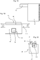
- a guide groove 27 is provided in the rear half of the mounting rail 20. This guide groove 27 has undercuts, so that, as can be seen from the 6 seen, a T-beam extension of the first mounting base 30 can engage. In this respect, z-forces are transferred to several contact surfaces.
- the first mounting base 30 can be moved back and forth in the rear area of the mounting rail 20 .
- the second mounting base 30' can be arranged on the mounting rail 20 in a corresponding manner.
- the attachment mechanism of the second mounting base 30 ' differs significantly.
- the second mounting base 30' can be inserted from below into corresponding mounting base bores 25, 25', 25", 25′′′ of the mounting rail 20 with two guide pins provided for this purpose.
- the second mounting base 30' is thus fixed in the longitudinal direction v with respect to the mounting rail 20
- the upper side of the second mounting base 30' can be fitted with detachable engagement elements which encompass the lower engagement strips 22a, 22b, so that z-forces can also be dissipated via the second mounting base 30'.
- Both the first mounting base 30 and the second mounting base 30 ′ are designed to be arranged in perforated rails 114 or in perforated rail segments 61 .
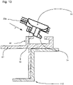
- the first mounting base 30 has a bar 34 which, as based on the 13 can be introduced obliquely into a perforated rail 114 or into a perforated rail segment 61.
- the lateral guide 10 can be folded down together with the first fastening base 30 and, if necessary, with the second fastening base 30', with the perforated pin 31 lying opposite the strip 34 engaging in corresponding holes in the perforated rail segment 61 .
- the bar 34 ensures that z-forces can be released.
- the perforated pins 31 secure the lateral guide against transverse displacement in the longitudinal direction (x-direction of the aircraft).
- two full hole pin 31 are provided.
- the second mounting base 30' also has two perforated pins 31' which can be introduced into a corresponding perforated rail from above. These perforated pins 31 ′ are also designed to prevent transverse displacement in the perforated rail 114 or in a perforated rail segment 61 .
- locking elements 32' are provided on the side of the perforated pins 31', which can be rotated from a rest position into a locking position in which the second fastening base 30' engages in the perforated rail 114 in such a way that z-forces are also dissipated be able.
- the side guide 10 as shown on the basis of Figures 3 to 7 was described, and the side guide 10, which from the Figures 10 and 11 as can be seen, in sloping perforated rail segments 61 and/or in sloping perforated rails 114.
- “running obliquely” means that the respective perforated rail 114 does not run parallel to the longitudinal direction (x-direction) of the aircraft.
- the fastening rail 20 runs parallel to the transverse direction of the aircraft (y-direction) despite the obliquely running perforated rails 114 or perforated rail segments 61 .
- a corresponding arrangement of the lateral guide 10 is made possible by the fact that the first and/or the second fastening base 30 , 30 ′ can be rotated relative to the longitudinal direction v of the fastening rail 20 .
- the 11 shows an example of the first mounting base 30 in a basic position in which the longitudinal direction v of the mounting rail 20 forms a right angle with a perforated rail axis I defined by the pin profile of the first mounting base 30 .
- the first fastening base 30 can be rotated by ⁇ 15° with respect to this basic position.
- a certain (lateral) play is provided in the form fit between the fastening rail 20 and the first fastening base 30 .
- the play results from the fact that the rail width, at least in the lower region (compare lower engagement strips 22a, 22b), has a rail width D1 that is smaller than a first clear width D2 of the fastening base.
- the base width D3 is smaller than the second clear width D4 of the first mounting base 30.
- the T-profile is of the Guide groove 27 spaced accordingly. In absolute values, the difference can be up to 7 mm, preferably 2 to 6 mm.
- the rail width D1 essentially corresponds to the first clear width D2 and/or the base width D3 essentially corresponds to the second clear width D4.
- a rotatability e.g. by 10° to 15°, can be achieved in this constellation in that the inner walls of the first and/or second fastening base 30, 30' have a convex shape at least in sections. This convex shape of the inner walls is preferably present where the inner walls bear vertically against sections of the fastening rail 20, in particular the engagement strips 22a, 22b, and/or face corresponding vertical sections on the fastening rail 20 with very little play.
- the difference can be in the interval from 1 to 20, in particular in the interval from 5 to 15%. According to the invention, it is possible to equip only the first mounting base 30 or only the second mounting base 30' with a corresponding clearance. In a preferred embodiment, both mounting bases 30, 30' have a corresponding play.
- the first mounting base 30 is preferably attached via a fitting 60 (cf 9 and 12 ) connected to the Z-profile 118 of the aircraft.
- a corresponding fitting can be screwed or riveted to the Z-profile 118 in the course of converting a passenger aircraft into a cargo aircraft.
- the 13 shows a cross section through a corresponding fitting 60, the fitting having an angle in its lower area in order to lie flat against the Z-profile 118.
- the perforated rail segment 61 is provided in the upper area.
- this can have one hole, two holes or three holes. Theoretically, it is also conceivable to provide more than three holes.
- the embodiment shown comprises an extension 62 on which panels can be arranged to form an accessible area of the cargo deck.
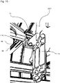
- the Figures 14 to 20 explain a further exemplary embodiment of the fitting 60, as shown schematically in 13 is shown.
- the side profile is not designed as a Z-profile 118 but rather as a type of box profile 118'.
- the 14 Figure 12 shows a view of a cargo deck where the side profile transitions from a Z profile 118 to a box profile 118'. The transition essentially takes place at frame 105". These special areas are located in the area of the cargo deck where the wing box is also located.
- the side profiles must be movably arranged in relation to frames 105", 105′′′.
- the embodiment of the fitting 60 shown enables a corresponding movement in the transverse direction of the aircraft (y-direction), with forces acting in the x- or z-direction being dissipated in the frames, in particular in the frames 105''' a carrier 70 is fastened to the frame 105′′′ with its fastening body 71.
- the carrier 70 has a carrier nose 74, which protrudes into the interior of the aircraft along the transverse direction of the aircraft 66 is provided, which preferably rests in a form-fitting manner in the z-direction and in the x-direction on the carrier lug 74.
- the carrier 70 it is not absolutely necessary for the carrier 70 to be screwed to the side of a frame with the fastening body 71 .
- the fastening body 71 can encompass projections of a frame and thus create a form fit with the frame. Furthermore, it is possible to attach the fastening body 71 to a base of the frame present in this area or to connect the fastening body directly or indirectly to the wing center box. This has the advantage that high forces can be gently introduced into this structure of the aircraft.
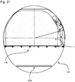
- FIG. 21 shows a section through the fuselage of an airplane. Shown in section are the upper and lower cargo decks 110 and 120, respectively.
- the container 1 is located on the upper cargo deck 110 and is slightly offset from the center of the cargo deck 110 (to the left in the plane of the drawing).
- the side guides 10, 10', 10" according to the invention enable a corresponding offset arrangement due to the displaceability of the side guide devices 40, 40'. In addition to the optimal utilization of the cargo deck, this arrangement has the advantage that dangerous goods, which have to be checked during the flight, can be transported.
Description
Die Erfindung betrifft eine Seitenführung zum Führen von Frachtstücken, eine Seitenführungsgruppe mit einer Vielzahl von entsprechenden Seitenführungen sowie ein mit einer entsprechenden Seitenführung oder Seitenführungsgruppe ausgestattetes Frachtdeck oder Flugzeug.The invention relates to a lateral guide for guiding freight items, a lateral guide group with a multiplicity of corresponding lateral guides and a cargo deck or aircraft equipped with a corresponding lateral guide or lateral guide group.
Es ist bekannt, dass Laderäume von Flugzeugen für unterschiedliche Verwendungszwecke häufig umgebaut werden. Beispielsweise kann es notwendig sein, ein Frachtdeck in Abhängigkeit von den zu ladenden Frachtstücken zu konfigurieren. Bei dem Transport von Ladung in Flugzeugen werden Frachtstücke, z.B. Container oder Paletten, mit genormten Abmessungen verwendet. So gibt es für Container/Paletten beispielsweise folgende Normgrößen: 223,5 auf 317,5 cm (88 Zoll x 125 Zoll), 243,8 cm auf 317,5 cm (96 Zoll x 125 Zoll), 223,5 cm auf 157,5 cm (88 Zoll x 62 Zoll), 153,4 auf 156,2 cm (60,4 x 61,5 Zoll), 119,3 auf 153,4 cm (47 x 60,4 Zoll) und verschiedenste Kombinationen hieraus. Im militärischen Bereich werden Paletten mit einer Abmessung von 274,3 cm auf 223,5 cm (108 Zoll x 88 Zoll) verwendet. Für besonders große Frachtstücke werden z.B. Paletten mit 243,8 auf 497,8 cm (96 x 196 Zoll) oder 243,8 auf 605,8 cm (96 x 238,5 Zoll) verwendet. Letztere werden auch als 16ft bzw. 20ft Paletten bezeichnet und orientieren sich an den Normgrößen von ISO668 (Intermodal) Containern für Seefracht bzw. LKW-Fracht. Zum Festhalten und Führen derartiger genormter Frachtstücke werden auf dem Frachtdeck montierte Seitenführungen verwendet. Für eine optimale Auslastung eines Frachtraums ist es notwendig, eine Vielzahl von Konfigurationsmöglichkeiten anzubieten, wobei ein schnelles Umrüsten des Frachtdecks eine hohe Priorität genießt. Geeignete Seitenführungen müssen schnell und einfach anbringbar und umkonfigurierbar sein, da die Kosten für das Betreiben von entsprechenden Flugzeugen sehr hoch sind. Des Weiteren soll die Konfiguration sehr einfach durchführbar sein, da das Personal, das diese Umkonfigurationen durchführt, häufig keine oder lediglich eine schlechte Schulung für die verwendeten Frachtdecks genossen hat. Hinzu kommt, dass die Seitenführungen sehr robust sein müssen, da diese sehr hohen Lasten ausgesetzt sind und eine schonende Behandlung aufgrund des hohen Zeitdrucks beim Be- und Entladen nicht gefordert werden kann.It is known that aircraft cargo holds are frequently converted for different uses. For example, it may be necessary to configure a cargo deck depending on the cargo items to be loaded. When transporting cargo in aircraft, freight items, eg containers or pallets, with standardized dimensions are used. For example, there are the following standard sizes for containers/pallets: 223.5 by 317.5 cm (88 inches x 125 inches), 243.8 cm by 317.5 cm (96 inches x 125 inches), 223.5 cm by 157 .5 cm (88 inches x 62 inches), 153.4 by 156.2 cm (60.4 by 61.5 inches), 119.3 by 153.4 cm (47 by 60.4 inches) and various combinations thereof . In the military sector, pallets measuring 274.3 cm by 223.5 cm (108 inches by 88 inches) are used. Pallets measuring 243.8 by 497.8 cm (96 x 196 inches) or 243.8 by 605.8 cm (96 x 238.5 inches), for example, are used for particularly large freight items. The latter are also referred to as 16ft or 20ft pallets and are based on the standard sizes of ISO668 (intermodal) containers for sea freight or truck freight. To hold and guide such standardized cargo are mounted on the cargo deck side rails used. In order to optimally utilize a cargo hold, it is necessary to offer a large number of configuration options, with a high priority being given to quickly converting the cargo deck. Suitable side guides must be able to be attached and reconfigured quickly and easily, since the costs for operating the corresponding aircraft are very high. Furthermore, the configuration should be very easy to carry out, since the personnel who carry out these reconfigurations have often had no or only poor training for the cargo decks used. In addition, the side guides have to be very robust, since they are exposed to very high loads and careful handling cannot be required due to the high time pressure when loading and unloading.
Ein Frachtdeck mit entsprechenden Seitenführungen ist häufig der Nässe, hohen Temperaturunterschieden, Staub und anderen rohen Einflüssen ausgesetzt. Ein defektes Frachtdeck - auch bereits ein defektes Funktionselement (Rolle, Führung, Riegel, Kralle) des Frachtdecks - kann dazu führen, dass der Stellplatz nicht verwendet werden kann, oder im schlechtesten Fall das entsprechende Flugzeug für mehrere Tage nicht eingesetzt werden kann. Ein derartiger Ausfall ist sehr teuer.A cargo deck with corresponding side rails is often exposed to moisture, high temperature differences, dust and other harsh influences. A defective cargo deck - even a defective functional element (roller, guide, bolt, claw) of the cargo deck - can mean that the parking space cannot be used, or in the worst case the aircraft in question cannot be used for several days. Such a failure is very expensive.
Die Bestückung des Frachtdecks eines Flugzeugs macht sich bei dem Gesamtgewicht des Flugzeugs deutlich bemerkbar, so dass es wünschenswert ist, hier Gewicht einzusparen.The equipment on the cargo deck of an aircraft is clearly noticeable in the total weight of the aircraft, so that it is desirable to save weight here.
Aus der
Aus der
Es ist eine Aufgabe der vorliegenden Erfindung eine Seitenführung für ein Frachtdeck, das eine Vielzahl von unterschiedlichen Konfigurationen ermöglicht, bereitzustellen, die robust ist, sich einfach bedienen lässt und bei einer Bestückung zu einem Frachtdeck mit einem geringen Gewicht führt. Des Weiteren soll eine entsprechende Seitenführungsgruppe und ein entsprechendes Frachtdeck bereitgestellt werden.It is an object of the present invention to provide a side guide for a cargo deck that enables a multitude of different configurations, that is robust, easy to operate and, when equipped, results in a cargo deck with a low weight. Furthermore, a corresponding lateral guidance group and a corresponding cargo deck are to be provided.
Eine weitere Herausforderung in diesem Feld der Technologie besteht darin, dass Flugzeuge teilweise im Lauf ihrer Nutzungszeit in unterschiedlicher Art und Weise eingesetzt werden. So verwendet man moderne Maschinen häufig für den Transport von Passagieren, so dass im oberen Deckbereich Sitze für die Passagiere angebracht sind und der untere Deckbereich zum Aufnehmen von Frachtstücken ausgestattet ist. Diese Maschinen werden manchmal umgerüstet ("conversion"), wobei auch das Passagierdeck in ein oberes Frachtdeck umgewandelt wird, so dass auch hier Frachtstücke, insbesondere Paletten und Container, untergebracht werden können. Bei einer derartigen Umrüstung werden die Sitze entfernt und die Bodenpaneele ausgebaut. Danach werden bestehende Sitzschienen ersetzt und teilweise neue Sitzschienen angebracht. Auch ist es üblich, Sitzschienenteilsegmente anzubringen, um innerhalb der Sitzschienen bzw. Lochschienen Funktionselemente, beispielsweise Seitenführungen oder andere Riegel, anzubringen. Ein entsprechender Umbau ist aufwendig und teuer. Es ist daher eine weitere Aufgabe der vorliegenden Erfindung, einen derartigen Umbau möglichst einfach zu gestalten und Flugzeuge mit einem möglichst funktionalen Frachtdeck auszustatten, wobei stets versucht wird das Gewicht des Frachtdecks so gering wie möglich zu halten.Another challenge in this field of technology is that aircraft are sometimes used in different ways over the course of their useful life. Thus, modern machines are often used for the transport of passengers, so that seats for the passengers are fitted in the upper deck area and the lower deck area is equipped for accommodating freight. These machines are sometimes converted ("conversion"), with the passenger deck also being converted into an upper cargo deck, so that freight items, in particular pallets and containers, can also be accommodated here. Such a conversion involves removing the seats and removing the floor panels. After that, existing seat rails are replaced and some new seat rails are installed. It is also customary to attach seat rail part segments in order to attach functional elements, for example side guides or other bars, within the seat rails or perforated rails. A corresponding conversion is complex and expensive. It is therefore a further object of the present invention to make such a conversion as simple as possible and to equip aircraft with a cargo deck that is as functional as possible, with the attempt always being made to keep the weight of the cargo deck as low as possible.
Die besagten Aufgaben werden durch den Gegenstand des Anspruchs 1 gelöst.Said objects are solved by the subject matter of
Insbesondere werden die Aufgaben durch eine Seitenführung zum Führen und/oder Halten von Frachtstücken in einem Flugzeug gelöst, wobei die Seitenführung umfasst:
- eine sich in Längsrichtung erstreckende Befestigungsschiene;
- mindestens eine Seitenführungsvorrichtung, die in Längsrichtung an unterschiedlichen Positionen an der Befestigungsschiene befestigbar ist,
- mindestens eine erste und mindestens eine zweite Befestigungsvorrichtung zur Befestigung der Seitenführung in einer jeweiligen Lochschiene auf einem Frachtdeck des Flugzeugs,
- a longitudinally extending mounting rail;
- at least one lateral guide device which can be fastened to the fastening rail at different positions in the longitudinal direction,
- at least one first and at least one second fastening device for fastening the lateral guide in a respective perforated rail on a cargo deck of the aircraft,
Seitenführungen in Flugzeugen werden üblicherweise dazu verwendet, Frachtstücke in Längsrichtung (x-Richtung) des Flugzeugs (von Bug zu Heck, oder von Heck zu Bug) zu leiten. Während des Fluges nehmen sie Kräfte quer (y- und z-Richtung) zur Längsrichtung auf und halten die Frachtstücke in ihrer Position.Lateral guides in aircraft are usually used to guide freight items in the longitudinal direction (x-direction) of the aircraft (from nose to tail, or from tail to nose). During the flight, they absorb forces transverse (y and z direction) to the longitudinal direction and hold the freight items in their position.
Ein Gedanke der vorliegenden Erfindung besteht darin, dass die Seitenführungsvorrichtung, die die eigentliche Führungs- und Haltefunktion der Seitenführung wahrnimmt, verschiebbar in einem Befestigungsrahmen gelagert ist. Die Seitenführungsvorrichtung kann also unterschiedliche Positionen einnehmen, um Frachtstücke mit unterschiedlichen Abmessungen zu halten und zu führen. Somit können zahlreiche Seitenführungsvorrichtungen, die an unterschiedlichen Positionen innerhalb des Frachtdecks angeordnet werden müssen, eingespart werden. Vorzugsweise lässt sich die mindestens eine Seitenführungsvorrichtung entlang der Befestigungsschiene verschieben.One idea of the present invention is that the lateral guide device, which performs the actual guiding and holding function of the lateral guide, is slidably mounted in a fastening frame. The lateral guide device can therefore assume different positions in order to hold and guide freight items with different dimensions. In this way, numerous lateral guide devices that have to be arranged at different positions within the cargo deck can be saved. The at least one lateral guide device can preferably be displaced along the fastening rail.
Ein weiterer Gedanke der vorliegenden Erfindung besteht darin, dass die erste Befestigungsvorrichtung die Befestigungsschiene derart umgreift und/oder in die Befestigungsschiene eingreift, dass die erste Befestigungsvorrichtung ebenfalls in Längsrichtung verschiebbar ist. Die Befestigungsvorrichtung kann beispielsweise ein Befestigungssockel sein, der mit entsprechenden Zapfen oder Leisten zur Fixierung der Befestigungsschiene am Frachtdeck in entsprechende Lochschienen eingreift. Die Verschiebbarkeit der ersten Befestigungsvorrichtung hat diverse Vorteile. Zum einen können Seitenführungen, die mit entsprechenden verschiebbaren Befestigungsvorrichtungen ausgestattet sind, einfacher am Frachtdeck montiert werden. Weiterhin sind entsprechend ausgestattete Seitenführungen an einer Vielzahl von Stellen einsetzbar. So kann beispielsweise im Heck des Flugzeugs der Frachtraum verengt sein, so dass andere Lochschienenabstände vorgegeben sind. Durch die Verschiebbarkeit der ersten Befestigungsvorrichtung kann die gleiche Seitenführung auch dort eingesetzt werden.A further idea of the present invention is that the first fastening device encompasses the fastening rail and/or engages in the fastening rail in such a way that the first fastening device can also be displaced in the longitudinal direction. The fastening device can be a fastening base, for example, which engages in corresponding perforated rails with corresponding pins or strips for fixing the fastening rail on the cargo deck. The displaceability of the first fastening device has various advantages. On the one hand, side guides that are equipped with corresponding sliding fastening devices can be mounted more easily on the cargo deck. Furthermore, appropriately equipped lateral guides can be used in a large number of places. For example, the cargo hold can be narrowed in the rear of the aircraft, so that other perforated rail distances are specified. Due to the displaceability of the first fastening device, the same side guide can also be used there.
Von einem Fertigungsaspekt lassen sich entsprechende Seitenführungen industriell fertigen und für eine Vielzahl von unterschiedlichen Flugzeugen einsetzen.From a production aspect, corresponding lateral guides can be manufactured industrially and used for a large number of different aircraft.
Die Verwendung einer Befestigungsschiene an Stelle von einem Befestigungsrahmen bzw. einem U-Profil hat den weiteren Vorteil, dass bei sehr geringem Gewicht eine hochfunktionale Seitenführung bereitgestellt werden kann. Auch ist es bedingt durch die Verwendung der Befestigungsschiene möglich, die Bauhöhe der Seitenführung, zumindest im führungsvorrichtungsfreien Bereich zu verringern.The use of a fastening rail instead of a fastening frame or a U-profile has the further advantage that a highly functional lateral guide can be provided with a very low weight. It is also possible, due to the use of the fastening rail, to reduce the structural height of the lateral guide, at least in the area free of the guide device.
In einer Ausführungsform hat die Befestigungsschiene einen Querschnitt eines Doppel-T-Trägers. Der obere Abschnitt des T-Trägers kann dazu verwendet werden, um einen Formschluss zu der mindestens einen Seitenführungsvorrichtung herzustellen. Der untere Abschnitt des T-Trägers kann einen entsprechenden Formschluss mit einer oder mehreren Befestigungsvorrichtungen herstellen. Die einzelnen T-Träger des Doppel-T-Trägers helfen also, Zuglasten (z-Richtung) effizient in die Struktur des Flugzeugs einzuleiten. Weiterhin ermöglicht diese Form, die Verschiebbarkeit der Befestigungsvorrichtungen sowie der mindestens einen Seitenführungsvorrichtung zu gewährleisten.In one embodiment, the mounting rail has a cross-section of an I-beam. The upper section of the T-beam can be used to create a form fit with the at least one lateral guide device. The lower section of the T-bar can form a corresponding form fit with one or more fastening devices. The individual T-beams of the double T-beam therefore help to efficiently introduce tensile loads (z-direction) into the structure of the aircraft. Furthermore, this shape makes it possible to ensure the displaceability of the fastening devices and the at least one lateral guide device.
Erfindungsgemäß lässt sich der Doppel-T-Trägerquerschnitt auch als X-Querschnitt definieren. In anderen Worten müssen die Querbalken der einzelnen T-Träger nicht zwangsläufig über die gesamte Länge parallel zueinander verlaufen, sondern können, insbesondere mittig, eine gewissen Neigung aufweisen.According to the invention, the I-beam cross section can also be defined as an X cross section. In other words, the crossbeams of the individual T-beams do not necessarily have to run parallel to one another over the entire length, but can have a certain inclination, in particular in the middle.
In einer Ausführungsform ist mindestens eine der Befestigungsvorrichtungen über einen Formschluss mit (Seiten-)Spiel derart an der Befestigungsschiene befestigt, dass die Befestigungsschiene aus einer Grundstellung gegenüber der Befestigungsvorrichtung verdrehbar ist. Die Verdrehbarkeit kann derart ausgestaltet sein, dass gegenüber der Grundstellung eine Verdrehung von mindestens 10° oder von mindestens 20° möglich ist. Diese Verdrehung kann sowohl in die Plus- als auch in die Minus-Richtung erfolgen.In one embodiment, at least one of the fastening devices is fastened to the fastening rail via a form fit with (lateral) play in such a way that the fastening rail can be rotated from a basic position relative to the fastening device. The ability to rotate can be designed in such a way that a rotation of at least 10° or at least 20° is possible in relation to the basic position. This rotation can take place both in the plus and in the minus direction.
Erfindungsgemäß kann die Grundstellung derart definiert sein, dass die Befestigungsvorrichtung im Wesentlichen quer zur Befestigungsschiene verläuft. Soweit die Befestigungsvorrichtung in eine Lochschiene einrastet, bilden die Lochschiene mit der Befestigungsschiene in der Grundstellung einen rechten Winkel.According to the invention, the basic position can be defined in such a way that the fastening device runs essentially transversely to the fastening rail. If the fastening device snaps into a perforated rail, the perforated rail forms a right angle with the fastening rail in the basic position.
Das Spiel beim Eingriff in die Befestigungsschiene ermöglicht ein Verdrehen gegenüber dieser Grundstellung.The game when engaging in the mounting rail allows twisting relative to this basic position.
Die hierdurch erreichten Freiheitsgrade können eingesetzt werden, um die erfindungsgemäße Seitenführung auch in Lochschienen bzw. Lochschienensegmenten zu verankern, die nicht in Längsrichtung des Flugzeugs verlaufen. Wie bereits erläutert, verengt sich der Frachtraum im Heckbereich, so dass hier entsprechend schräg verlaufende Lochschienen vorgesehen sein können.The degrees of freedom achieved in this way can be used to anchor the lateral guide according to the invention also in perforated rails or perforated rail segments that do not run in the longitudinal direction of the aircraft. As already explained, the cargo space narrows in the rear area, so that perforated rails running at an angle can be provided here accordingly.
Es ist möglich, mindestens eine Seitenführungsvorrichtung derart auszugestalten, dass sie nach oben hin (z-Richtung) abnehmbar und an einer anderen Position festsetzbar ist. Vorzugsweise wird jedoch bei mindestens einer Seitenführungsvorrichtung ein Formschluss zur Befestigungsschiene hergestellt, so dass nur eine Verschiebbarkeit in Längsrichtung der Befestigungsschiene möglich ist. Die mindestens eine Seitenführungsvorrichtung umgreift die Befestigungsschiene und hat im unteren Bereich den Querschnitt eines C-Profils. Ein Austausch der Seitenführungsvorrichtung kann dennoch dadurch erreicht werden, dass die Seitenführungsvorrichtung über eines der Enden der Befestigungsschiene hinausgeschoben wird. Hierdurch kann eine einfache Wartung bzw. ein einfacher Austausch der Seitenführungsvorrichtungen gewährleistet werden. Erfindungsgemäß können so einmal installierte Befestigungsschienen mit unterschiedlichen Seitenführungsvorrichtungen ausgestattet werden, um unterschiedliche Konfigurationen anbieten zu können.It is possible to design at least one lateral guide device in such a way that it can be removed upwards (z-direction) and fixed in a different position. Preferably, however, a positive connection to the fastening rail is produced in at least one lateral guide device, so that the fastening rail can only be displaced in the longitudinal direction. The at least one lateral guide device encompasses the fastening rail and has the cross section of a C-profile in the lower area. The lateral guide device can nevertheless be replaced by pushing the lateral guide device beyond one of the ends of the fastening rail. In this way, simple maintenance or simple replacement of the lateral guide devices can be guaranteed. According to the invention, once installed, fastening rails can be equipped with different lateral guide devices in order to be able to offer different configurations.
In einer Ausführungsform weist die Seitenführung mindestens eine Führungsrolle auf, die in der Befestigungsschiene um eine Rotationsachse drehbeweglich gelagert ist. Die Rotationsachse verläuft im Wesentlichen parallel zur Längsrichtung der Befestigungsschiene, so dass Frachtstücke quer zur Befestigungsschiene transportiert bzw. geführt werden können. Zur Aufnahme der Führungsrolle, gegebenenfalls mit einem Gehäuse, weist die Befestigungsschiene in einer bevorzugten Ausführungsform eine nach oben hin offene Aussparung, beispielsweise in Form eines V-Profils, auf. Das Gehäuse der Führungsrolle kann eine korrespondierende Form, insbesondere eine V-Form haben.In one embodiment, the lateral guide has at least one guide roller, which is mounted in the fastening rail so that it can rotate about an axis of rotation. The axis of rotation runs essentially parallel to the longitudinal direction of the fastening rail, so that freight items can be transported or guided transversely to the fastening rail. In order to accommodate the guide roller, possibly with a housing, the fastening rail has, in a preferred embodiment, a recess which is open towards the top, for example in the form of a V-profile. The housing of the guide roller can have a corresponding shape, in particular a V shape.
Je nach Ausführungsform kann die Führungsrolle bzw. die Achse der Führungsrolle mit der Seitenführungsvorrichtung verbunden sein oder nicht. In einer Ausführungsform ist ein/das Gehäuse der Führungsrolle integraler Bestandteil der Seitenführungsvorrichtung. In einer anderen Ausführungsform lässt sich die Führungsrolle zusammen mit dem Gehäuse entnehmen und derart einsetzen, dass eine Verschiebung der Führungsrolle in Längsrichtung nicht mehr möglich ist.Depending on the embodiment, the guide roller or the axis of the guide roller can be connected to the lateral guide device or not. In one embodiment, a/the housing of the guide roller is an integral part of the lateral guide device. In another embodiment, the Remove the guide roller together with the housing and insert it in such a way that it is no longer possible to move the guide roller in the longitudinal direction.
Die Seitenführung weist also mindestens eine Führungsrolle auf, die den Transport der Frachtstücke erleichtert. Diese Führungsrolle nimmt also wie auch die Seitenführungsvorrichtung unterschiedliche Positionen ein. Durch das bewegliche Lagern der Führungsrolle können eine Vielzahl von Führungsrollen eingespart werden. Des Weiteren ist ein modernes Frachtdeck so dicht mit Funktionselementen (z.B. Seitenführungen, Führungsrollen, Riegelkrallen, PDUs) bestückt, dass es häufig schwierig ist, den richtigen Platz für die nötigen Funktionselemente auf dem Frachtdeck zu finden. Durch das erfindungsgemäße gezielte Einsparen von Führungsrollen und Seitenführungsvorrichtungen kann ein Frachtdeck hergestellt werden, das eine noch höhere Anzahl von unterschiedlichen Konfigurationen ermöglicht.The lateral guide therefore has at least one guide roller, which facilitates the transport of the freight items. Like the lateral guide device, this guide roller therefore assumes different positions. A large number of guide rollers can be saved as a result of the movable mounting of the guide roller. Furthermore, a modern cargo deck is so densely populated with functional elements (e.g. side guides, guide rollers, locking claws, PDUs) that it is often difficult to find the right place for the necessary functional elements on the cargo deck. Due to the targeted saving of guide rollers and lateral guide devices according to the invention, a cargo deck can be produced that enables an even greater number of different configurations.
Die Seitenführung kann mindestens eine Festsetzvorrichtung zum Festsetzen der Seitenführungsvorrichtung an mindestens zwei sich unterscheidenden Positionen an der Befestigungsschiene umfassen. Es ist möglich, die erfindungsgemäße Seitenführung derart auszugestalten, dass sie sich in einem Bereich verschieben lässt, in dem sie beim Beladen und Entladen die Funktion eines Anschlags zum Schutz der Struktur des Flugzeugs wahrnimmt. Diese Funktion wird speziell im Frachttürbereich, z.B. des oberen Frachtdecks, verwendet, wenn Frachtstücke, z.B. Container und/oder Paletten, durch "Reindrehen" geladen werden sollen, welche länger sind als die Frachttür breit ist. In diesem Fall werden die Seitenführungsvorrichtungen gegenüber der Frachttür soweit als möglich nach außen - nahe an die Außenhaut des Flugzeugs - geschoben, um einen möglichst großen Drehbereich zu erhalten.The lateral guide can include at least one fixing device for fixing the lateral guide device in at least two different positions on the fastening rail. It is possible to configure the lateral guide according to the invention in such a way that it can be moved in an area in which it performs the function of a stop to protect the structure of the aircraft during loading and unloading. This function is used especially in the cargo door area, e.g. the upper cargo deck, when cargo items, e.g. containers and/or pallets, which are longer than the cargo door are wide, are to be loaded by "turning in". In this case, the lateral guide devices are pushed outwards as far as possible in relation to the cargo door—close to the outer skin of the aircraft—in order to obtain the largest possible turning range.
Die Festsetzvorrichtung kann Rastelemente und Gegenrastelemente an definierten Positionen an der Befestigungsschiene umfassen. Geeignet ausgebildete Rastelemente und Gegenrastelemente ermöglichen die Einnahme von vordefinierten Positionen seitens der Seitenführungsvorrichtungen. Diese Positionen können so gewählt werden, dass Frachtstücke mit vorgegebenen Standardabmessungen geführt werden können. Insofern erleichtern diese Rast- und Gegenrastelemente das Einnehmen einer bestimmten vorgegebenen Konfiguration.The fixing device can include latching elements and counter-latching elements at defined positions on the fastening rail. Suitably designed latching elements and counter-latching elements enable the lateral guide devices to assume predefined positions. These positions can be selected in such a way that freight items with specified standard dimensions can be carried. In this respect, these latching and counter-latching elements make it easier to assume a certain predetermined configuration.
Die Festsetzvorrichtung kann mindestens einen Fixierungszapfen umfassen, der durch Bohrungen in der Befestigungsschiene gesteckt wird. In einer Ausführungsform laufen diese Bohrungen im angeordneten Zustand der Seitenführung in Längsrichtung des Flugzeugs - also quer zur Längsrichtung der Befestigungsschiene.The fixing device can include at least one fixing pin, which is inserted through holes in the mounting rail. In one embodiment, run these holes in the arranged state of the lateral guide in the longitudinal direction of the aircraft - that is, transverse to the longitudinal direction of the mounting rail.
Bei dem Fixierungszapfen kann es sich um einen Kugelsperrstift handeln, der beim Einbringen einrastet, so dass ein Herausgleiten des Fixierzapfens, beispielsweise aufgrund von Vibrationen, verhindert wird. Durch einen am Kopf des Stifts vorgesehenen Knopf lässt sich die Sperrung lösen, so dass ein einfaches Entnehmen des Fixierungszapfens möglich ist.The fixation pin can be a ball-locking pin, which engages during insertion, so that the fixation pin is prevented from slipping out, for example due to vibrations. The lock can be released by means of a button provided on the head of the pin, so that the fixing pin can be easily removed.
In einer Ausführungsform lässt sich mindestens eine Seitenführungsvorrichtung in einer Position relativ nahe am Ende der Befestigungsschiene festsetzen.In one embodiment, at least one cornering device is lockable in a position relatively near the end of the mounting rail.
Beispielsweise kann ein Festsetzen innerhalb von 5 cm vom Ende der Befestigungsschiene erfolgen. Durch die Vorgabe einer entsprechenden Fixierungsposition derart weit außen - nahe an der Flugzeughaut - ist es möglich, beispielsweise im Be- und Entladebereich derart viel Platz einzuräumen, dass ein problemloses Drehen der Fracht in diesem Bereich möglich ist. Gleichzeit dient die Führungsvorrichtung aber noch als Anschlag zum Schutz der Flugzeugstruktur.For example, sticking can occur within 5 cm of the end of the mounting rail. By specifying a corresponding fixing position so far outside - close to the aircraft skin - it is possible, for example in the loading and unloading area, to allow so much space that the cargo can be turned in this area without any problems. At the same time, the guide device also serves as a stop to protect the aircraft structure.
Die Befestigungsschiene kann eine Breite von maximal 10 cm, insbesondere von maximal 8 cm, haben. In einer Ausführungsform ist die Befestigungsschiene lediglich ca. 6 cm breit.The fastening rail can have a maximum width of 10 cm, in particular a maximum of 8 cm. In one embodiment, the mounting rail is only about 6 cm wide.
Die Befestigungsschiene kann eine Befestigungslänge von mindestens 15, 20, 30 oder 50 cm haben. Auch längere Ausführungsformen (z.B. 1 m bis 1.5 m) sind denkbar. In diesem Fall überspannt die Befestigungsschiene mindestens zwei, vorzugsweise drei oder auch mehrere Lochschienen. In solchen Fällen wird die Befestigungsschiene mittels der nötigen Anzahl von Befestigunsvorrichtungen an jeder gekreuzten bzw. überspannten Lochschiene befestigt.The fastening rail can have a fastening length of at least 15, 20, 30 or 50 cm. Longer versions (e.g. 1 m to 1.5 m) are also conceivable. In this case, the fastening rail spans at least two, preferably three or more perforated rails. In such cases, the fastening rail is fastened to each crossed or spanned perforated rail using the necessary number of fastening devices.
In einer Ausführungsform ist die Befestigungsschiene also relativ lang, so dass die Befestigungspunkte, in denen die Befestigungsvorrichtungen angebracht sind, relativ weit auseinanderliegen können. Dies führt zwar dazu, dass die Befestigungsschiene aufgrund der Länge schwerer wird. Andererseits kann bei der Umrüstung eines Flugzeugs darauf verzichtet werden, zusätzliche Lochschienen bzw. Sitzschienen für die Seitenführung vorzusehen, wodurch Gewicht in erheblichem Maße eingespart werden kann. In einer Ausführungsform werden für die Befestigung der Seitenführung nur dort Lochschienen vorgesehen, wo sich Längsträger befinden.In one embodiment, the fastening rail is therefore relatively long, so that the fastening points, in which the fastening devices are attached, can be relatively far apart. Although this means that the mounting rail is heavier due to the length. On the other hand, when converting an aircraft, there is no need to provide additional perforated rails or seat rails for the lateral guide, which means that weight can be saved to a considerable extent. In one embodiment, perforated rails are only provided where longitudinal beams are located for fastening the lateral guide.
Eine der Seitenführungsvorrichtungen kann einen Anschlag und/oder eine Riegelkralle umfassen, der bzw. die derart an der Befestigungsschiene befestigt ist, dass der Anschlag bzw. die Riegelkralle von einer hochgestellten Arbeitsposition in eine abgesenkte Ruheposition verschwenkbar ist. Insofern ist es nicht nur möglich, dass der Anschlag bzw. die Riegelkralle an der Seitenführungsvorrichtung verschiedene Funktionspositionen einnimmt, um die Frachtstücke in diesen zu führen und zu halten. Zusätzlich kann der Anschlag oder die Riegelkralle abgesenkt werden, so dass sie von Frachtstücken überfahrbar sind. Somit lassen sich weitere Konfigurationen des Frachtdecks gewährleisten. Es kann ein Frachtdeck geschaffen werden, das flexibel für die Verriegelung unterschiedlicher Frachtstück-Grössen angepasst werden kann. Es so ebenfalls möglich, ein Frachtdeck zu schaffen, das keine (überstehende) Seitenführungen aufweist und z.B. zur Beladung von einem Fahrzeug mit einer oder mehreren Platten überdeckt werden kann.One of the lateral guide devices can include a stop and/or a locking claw which is fastened to the fastening rail in such a way that the stop or locking claw can be pivoted from a raised working position into a lowered rest position. In this respect, it is not only possible for the stop or the locking claw on the lateral guide device to assume different functional positions in order to guide and hold the freight items in them. In addition, the stop or the locking claw can be lowered so that freight items can drive over them. This means that further configurations of the cargo deck can be guaranteed. A cargo deck can be created that can be flexibly adapted to lock different sizes of cargo. It is also possible to create a cargo deck that does not have any (overhanging) side rails and can be covered with one or more panels, e.g. for loading a vehicle.
In einer Ausführungsform hat die Seitenführung zwei Seitenführungsvorrichtungen, wobei die innenliegende Seitenführungsvorrichtung zwischen der Arbeitsposition und der Ruheposition verschwenkbar ist.In one embodiment, the lateral guide has two lateral guide devices, the internal lateral guide device being pivotable between the working position and the rest position.
Die Seitenführungsvorrichtung kann um eine Schwenkachse drehbeweglich an der Befestigungsschiene befestigt sein.The lateral guide device can be fastened to the fastening rail so that it can rotate about a pivot axis.
Der Anschlag bzw. die Riegelkralle an der Seitenführungsvorrichtung kann auf mindestens einer Seite Schrägflächen aufweisen, um diese beim seitlichen Überfahren durch ein Frachtstück aus der Arbeitsposition in die Ruheposition zu bewegen.The stop or the locking claw on the lateral guide device can have inclined surfaces on at least one side in order to move them from the working position to the rest position when a piece of freight runs over them from the side.
Die Seitenführungsvorrichtung kann mindestens eine Riegelkralle zum zumindest abschnittsweisen Umgreifen der Frachtstücke umfassen.The lateral guidance device can comprise at least one locking claw for at least partially encompassing the freight items.
Die Riegelkralle kann federnd an der Befestigungsschiene befestigt sein. Insofern ist es möglich, auf die Riegelkralle wirkende Kräfte federnd aufzunehmen und über die Befestigungsschiene in das Frachtdeck abzuleiten.The locking claw can be resiliently attached to the mounting rail. In this respect, it is possible to absorb forces acting on the locking claw in a resilient manner and to divert them into the cargo deck via the fastening rail.
In einer Ausführungsform ist mindestens eine Befestigungsvorrichtung derart ausgestattet, dass sie sich schräg in eine Lochschiene einbringen und dort durch ein Herabsenken in die horizontale Ebene verankern lässt. Beispielsweise kann die erste bzw. zweite Befestigungsvorrichtung eine Leiste zum Einführen der Befestigungsvorrichtung in die jeweilige Lochschiene entlang einer Einbringrichtung und mindestens einen der Leiste gegenüberliegenden Zapfen zum Sichern der Befestigungsvorrichtung gegen einen Verschub quer zur Einbringrichtung aufweisen. Vorzugsweise ist die jeweilige Befestigungsvorrichtung derart ausgestaltet, dass der gegenüberliegende Zapfen im angeordneten Zustand der Seitenführung in einem Loch der Lochschiene sitzt.In one embodiment, at least one fastening device is equipped in such a way that it can be introduced at an angle into a perforated rail and anchored there by being lowered into the horizontal plane. For example, the first or second fastening device have a strip for inserting the fastening device into the respective perforated rail along an insertion direction and at least one pin opposite the strip for securing the fastening device against displacement transversely to the insertion direction. The respective fastening device is preferably designed in such a way that the opposite pin sits in a hole in the perforated rail when the lateral guide is in the arranged state.
In einer Ausführungsform sind von diesen Zapfen mindestens zwei gegenüberliegend zu der Leiste vorgesehen, so dass in Querrichtung wirkende Kräfte effizient an die entsprechende Lochschiene weitergegeben werden können.In one embodiment, at least two of these pins are provided opposite to the bar, so that forces acting in the transverse direction can be efficiently passed on to the corresponding perforated rail.
Die oben genannte Aufgabe wird ebenfalls durch eine Seitenführungsgruppe gelöst, wobei diese Seitenführungsgruppe eine Vielzahl von Seitenführungen, wie diese bereits beschrieben wurden, umfasst, wobei die Seitenführungsvorrichtungen der einzelnen Seitenführungen mindestens eine gemeinsame Profilschiene aufweisen, die verschiebbar an der Befestigungsschiene befestigt ist. Die Schiene kann starr oder abnehmbar mit den einzelnen Seitenführungsvorrichtungen verbunden sein und die Frachtstücke führen.The above-mentioned object is also achieved by a lateral guide group, this lateral guide group comprising a large number of lateral guides as already described, the lateral guide devices of the individual lateral guides having at least one common profile rail which is slidably fastened to the fastening rail. The rail can be rigidly or detachably connected to the individual side guide devices and guide the freight items.
Die Schiene kann Riegelkrallen, vorzugsweise von sich unterscheidenden Typen, aufweisen. Da sich die Frachtstücke nicht nur in ihren Querabmessungen sondern auch in ihren Längsabmessungen unterscheiden, ist es vorteilhaft, wenn die Schiene sich über längere Abschnitte erstreckt. Insofern können geeignete Funktionselemente, insbesondere Riegelkrallen, so vorgesehen werden, dass für jedes Frachtstück eine geeignete Halterung bereitsteht. Die Riegelkrallen können unmittelbar oberhalb eines entsprechenden Befestigungsrahmens oder diesbezüglich versetzt angeordnet werden. Es ist also möglich, die Position der Funktionselemente in Längsrichtung des Flugzeugs unabhängig von der Position der Befestigungsschienen zu wählen. Des Weiteren kann eine Schiene eine Vielzahl von unterschiedlichen Riegelkrallen aufnehmen, die vorzugsweise in sich unterscheidenden Abständen hieran angeordnet sind.The rail may have locking claws, preferably of different types. Since the freight items differ not only in their transverse dimensions but also in their longitudinal dimensions, it is advantageous if the rail extends over longer sections. In this respect, suitable functional elements, in particular locking claws, can be provided in such a way that a suitable holder is available for each piece of freight. The locking claws can be arranged directly above a corresponding fastening frame or offset in relation thereto. It is therefore possible to choose the position of the functional elements in the longitudinal direction of the aircraft independently of the position of the fastening rails. Furthermore, a rail can accommodate a large number of different locking claws, which are preferably arranged on it at different distances.
Besonders im Be- und Entladebereich ist eine entsprechende Seitenführungsgruppe besonders vorteilhaft, da hier die Fracht teilweise schräg in den Frachtraum hineinfährt.A corresponding lateral guide group is particularly advantageous in the loading and unloading area, since the freight sometimes enters the cargo hold at an angle here.
Des Weiteren wird die Aufgabe durch ein Frachtladedeck mit mindestens einer der beschriebenen Seitenführungsgruppen und/oder mit mindestens einer der beschriebenen Seitenführungen gelöst.Furthermore, the object is achieved by a cargo loading deck with at least one of the lateral guide groups described and/or with at least one of the lateral guides described.
Für ein entsprechendes Frachtladedeck ergeben sich ähnliche Vorteile, wie sie bereits in Verbindung mit der Seitenführung bzw. der Seitenführungsgruppe beschrieben wurden.Similar advantages result for a corresponding cargo loading deck as have already been described in connection with the lateral guide or the lateral guide group.
Die eingangs skizzierten Aufgaben, insbesondere die der leichteren Umrüstung eines Passagierflugzeugs in ein Frachtflugzeug, werden weiterhin durch ein Flugzeug gemäß dem Anspruch 13 gelöst.The tasks outlined at the outset, in particular that of making it easier to convert a passenger aircraft into a cargo aircraft, are also achieved by an aircraft according to claim 13 .
Insbesondere wird die Aufgabe durch ein Flugzeug mit einem Frachtdeck gelöst, wobei das Flugzeug die nachfolgenden Tragstrukturelemente umfasst:
- Flugzeugaußenhaut,
- mit der Flugzeugaußenhaut verbundene Spanten;
- an den Spanten befestigte Querträger;
- an den Querträgern befestigte Längsträger;
- parallel zu den Querträgern verlaufende Seitenprofile, insbesondere Z-Profile, die über Scherträger (unmittelbar) mit der Flugzeugaußenhaut verbunden sind.
- aircraft skin,
- frames connected to the aircraft skin;
- cross members attached to the frames;
- side members attached to the cross members;
- Side profiles running parallel to the crossbeams, in particular Z-profiles, which are (directly) connected to the outer skin of the aircraft via shear beams.
Erfindungsgemäß ist das Flugzeug mit mindestens einer Seitenführung ausgestattet. Bei der Seitenführung kann es sich um eine der Seitenführungen handeln, wie diese vorab bereits beschrieben wurden. Die Seitenführung kann eine sich in Querrichtung des Flugzeugs erstreckende Befestigungsschiene sowie mindestens eine Seitenführungsvorrichtung, die an unterschiedlichen Positionen der Befestigungsschiene befestigbar ist, umfassen. Erfindungsgemäß kann die Befestigungsschiene über einen ersten Befestigungspunkt und einen zweiten Befestigungspunkt mit einigen der Tragstrukturelementen des Flugzeugs verbunden sein, wobei sich der erste Befestigungspunkt oberhalb eines der Seitenprofile und der zweite Befestigungspunkt oberhalb eines der Querträger befinden kann.According to the invention, the aircraft is equipped with at least one side guide. The lateral guide can be one of the lateral guides as already described above. The lateral guide can comprise a fastening rail extending in the transverse direction of the aircraft and at least one lateral guide device which can be fastened at different positions on the fastening rail. According to the invention, the fastening rail can be connected to some of the supporting structure elements of the aircraft via a first fastening point and a second fastening point, with the first fastening point being able to be located above one of the side profiles and the second fastening point being situated above one of the cross members.
Als Befestigungspunkt können erfindungsgemäß der Punkt bzw. die Region verstanden werden, in der auf die Seitenführung wirkende Zugkräfte (z-Richtung) hauptsächlich in die Tragstruktur des Flugzeugs eingeleitet werden. Soweit zur Befestigung Schrauben verwendet werden, ist der Befestigungspunkt im Wesentlichen die Region, in der die Schraube in die Tragstrukturelemente eingreift. Soweit als Befestigungsvorrichtungen Adapter verwendet werden, die in Sitzschienen eingreifen, so ist der Befestigungspunkt die Region, die der entsprechende Adapter definiert. Dass sich ein Befestigungspunkt oberhalb eines Elements, beispielsweise oberhalb des Seitenprofils, befindet, heißt nicht zwangsläufig, dass die Befestigung nicht innerhalb dieses Elements erfolgen kann.According to the invention, the attachment point can be understood as the point or the region in which tensile forces (z-direction) acting on the lateral guide are mainly introduced into the supporting structure of the aircraft. If screws are used for attachment, the attachment point is essentially the region in which the screw engages in the supporting structure elements. Insofar as adapters that engage in seat rails are used as fastening devices, the fastening point is the region that the corresponding adapter defines. The fact that an attachment point is above an element, for example above the side profile, does not necessarily mean that the attachment cannot take place within this element.
Die beschriebene erfindungsgemäße Lösung hat den Vorteil, dass in den Seitenbereichen des Frachtdecks, an denen ein relativ großer Abstand zwischen den Seitenprofilen und den Querträgern besteht, keine zusätzlichen Sitzschienen eingezogen werden müssen, die nicht (unmittelbar) oberhalb von Querträgern sitzen.The solution according to the invention described has the advantage that in the side areas of the cargo deck where there is a relatively large distance between the side profiles and the crossbeams, no additional seat rails that are not (immediately) located above crossbeams have to be drawn in.
Durch das Verzichten auf entsprechende Sitzschienen bzw. Lochschienen kann Gewicht eingespart werden.Weight can be saved by dispensing with corresponding seat rails or perforated rails.
In einer Ausführungsform kann zwischen dem ersten und dem zweiten bzw. nächsten Befestigungspunkt ein Abstand von mehr als 15 cm, insbesondere von mehr als 20 cm vorgesehen sein.In one embodiment, a distance of more than 15 cm, in particular more than 20 cm, can be provided between the first and the second or next attachment point.
Der erste Befestigungspunkt ist vorzugsweise relativ nahe an der Flugzeugaußenhaut vorgesehen. In einer Ausführungsform ist die kürzeste Distanz zwischen der Flugzeugaußenhaut und dem ersten Befestigungspunkt kleiner oder gleich 30 cm. Es sind auch Ausführungsformen möglich, bei denen diese Maximaldistanz kleiner als 25 oder kleiner als 20 cm ist.The first attachment point is preferably provided relatively close to the outer skin of the aircraft. In one embodiment, the shortest distance between the aircraft skin and the first attachment point is less than or equal to 30 cm. Embodiments are also possible in which this maximum distance is less than 25 or less than 20 cm.
In einer Ausführungsform ist die Befestigungsschiene am ersten Befestigungspunkt über ein Fitting an dem Seitenprofil befestigt. Zusätzlich oder alternativ kann die Befestigungsschiene am zweiten Befestigungspunkt an einer dem Querträger montierten Lochschiene befestigt sein.In one embodiment, the fastening rail is fastened to the side profile at the first fastening point via a fitting. Additionally or alternatively, the fastening rail can be fastened at the second fastening point to a perforated rail mounted on the cross member.
Das Verwenden eines Fittings erlaubt das einfache Nachrüsten eines Befestigungspunkts. Weiterhin kann durch die Verwendung eines Fittings mit einem (kurzen) Lochschienensegment gegenüber einer Lochschiene erheblich Gewicht eingespart werden.Using a fitting allows easy retrofitting of an attachment point. Furthermore, by using a fitting with a (short) perforated rail segment, considerable weight can be saved compared to a perforated rail.
In einer Ausführungsform ist mindestens eine Seitenführung im Bereich des Flügelmittelkastens ("wing box") angeordnet. Eine Anordnung in diesem Bereich erfordert besonders hohe Flexibilität, da es aufgrund des Vorhandenseins der Flügel in diesen Bereichen zu erheblichen Verformungen kommen kann. Die besagte Seitenführung kann erfindungsgemäß an einem/dem ersten Befestigungspunkt mit einem Schlitten verbunden sein, wobei der Schlitten in Querrichtung des Flugzeugs beweglich auf einem Vorsprung sitzt, der mit einem der Spanten und/oder dem Flügelmittelkasten verbunden ist. Aufgrund der Anordnung ist es möglich, dass eine Verformung der Spanten die Funktion der Seitenführung und des Frachtdecks nicht beeinflusst. Die geforderte Verformbarkeit ist gewährleistet. Entstehende Kräfte werden mittelbar (über den Spant) oder unmittelbar in den Flügelmittelkasten eingeleitet.In one embodiment, at least one lateral guide is arranged in the area of the wing center box ("wing box"). An arrangement in this area requires a particularly high degree of flexibility, since significant deformations can occur in these areas due to the presence of the wings. According to the invention, said lateral guide can be connected to a carriage at a/the first attachment point, the carriage being movably seated in the transverse direction of the aircraft on a projection which is connected to one of the frames and/or the wing center box. Due to the arrangement, it is possible that a deformation of the frames does not affect the function of the side rails and the cargo deck. The required deformability is guaranteed. The resulting forces are introduced directly (via the frame) or directly into the center wing box.
Der Schlitten kann eine sich in Querrichtung des Flugzeugs erstreckende Aufnahme aufweisen, in die der Vorsprung formschlüssig eingreift. Die Aufnahme verläuft vorzugsweise in Querrichtung des Flugzeugs. Die Aufnahme kann ein Gleitmittel und/oder eine Innenauskleidung aus gleitfähigem Material, z.B. Polyamid, und/oder Vorrichtungen zur kraftfreien Bewegung, z.B. Rollenlager, des Vorsprungs innerhalb der Aufnahme aufweisen, rechteckig oder quadratisch ausgebildet sein.The carriage can have a receptacle which extends in the transverse direction of the aircraft and into which the projection engages in a form-fitting manner. The recording preferably runs in the transverse direction of the aircraft. The receptacle may have a lubricant and/or an inner lining of lubricious material, e.g.
Weitere vorteilhafte Ausführungsformen ergeben sich aus den Unteransprüchen.Further advantageous embodiments emerge from the dependent claims.
Nachfolgend wird die Erfindung anhand von Zeichnungen näher erläutert. Hierbei zeigen:
- Fig. 1
- eine erste Ansicht eines Frachtdecks ohne Paneele, wobei eine Vielzahl von Seitenführungen angeordnet ist;
- Fig. 2
- eine weitere Ansicht auf das Frachtdeck aus
Fig. 1 ; - Fig. 3
- eine perspektivische Detailansicht einer erfindungsgemäßen Seitenführung;
- Fig. 4
- eine Seitenansicht auf die Seitenführung gemäß
Fig. 3 ; - Fig. 5
- eine Ansicht von unten auf die Seitenführung gemäß
Fig. 3 ; - Fig. 6
- eine Ansicht von hinten auf die Seitenführung gemäß
Fig. 3 ; - Fig. 7
- eine Ansicht von vorne auf die Seitenführung gemäß
Fig. 3 ; - Fig. 8
- verschiedene unterschiedliche Positionen, die die Seitenführungsvorrichtung der Seitenführung aus
Fig. 3 einnehmen kann; - Fig. 9
- eine Detailansicht auf den hinteren Teil der Seitenführung gemäß
Fig. 3 ; - Fig. 10
- eine weitere Variante der erfindungsgemäßen Seitenführung, wie diese bereits in den
Fig. 1 und 2 gezeigt wurde; - Fig. 11
- eine Ansicht von unten auf die Seitenführung gemäß
Fig. 10 ; - Fig. 12
- eine Detailansicht der Befestigungsvorrichtung von hinten;
- Fig. 13
- eine Detailansicht der Befestigungsvorrichtung von der Seite;
- Fig. 14
- eine weitere Ansicht auf ein Frachtdeck mit einer Vielzahl von Seitenführungen, wobei in
Fig. 14 der Bereich des Flügelmittelkastens gezeigt ist; - Fig. 15
- einen Befestigungskörper zur Befestigung der Seitenführung aus
Fig. 14 ; - Fig. 16 und 17
- weitere Ansichten auf dem Befestigungskörper aus
Fig. 15 ; - Fig. 18
- eine schematische Darstellung des Befestigungskörpers aus
Fig. 15 ; - Fig. 19
und 20 - schematische Darstellungen eines Schlittens zur Befestigung eines Fittings;
- Fig. 21
- einen schematischen Querschnitt durch einen Flugzeugrumpf mit oberem und unterem Frachtdeck.
- 1
- a first view of a cargo deck without panels, wherein a plurality of side guides are arranged;
- 2
- Another view of the
cargo deck 1 ; - 3
- a perspective detailed view of a lateral guide according to the invention;
- 4
- a side view of the lateral guide according to FIG
3 ; - figure 5
- a view from below of the lateral guide according to
3 ; - 6
- a rear view of the lateral guide according to FIG
3 ; - 7
- a front view of the lateral guide according to FIG
3 ; - 8
- various different positions that the lateral guide device of the lateral guide
3 can take; - 9
- a detailed view of the rear part of the lateral guide according to FIG
3 ; - 10
- Another variant of the lateral guide according to the invention, as already in the
Figures 1 and 2 was shown; - 11
- a view from below of the lateral guide according to
10 ; - 12
- a detailed view of the fastening device from behind;
- 13
- a detailed view of the fastening device from the side;
- 14
- another view of a cargo deck with a large number of side guides, in which
14 the wing center box area is shown; - 15
- a fastening body for fastening the lateral guide
14 ; - 16 and 17
- more views on the fastener body
15 ; - 18
- a schematic representation of the fastener body
15 ; - 19 and 20
- schematic representations of a carriage for attaching a fitting;
- 21
- a schematic cross section through an aircraft fuselage with upper and lower cargo deck.
Bei der nachfolgenden Beschreibung werden für gleiche und gleich wirkende Teile dieselben Bezugsziffern verwendet.In the following description, the same reference numerals are used for the same and identically functioning parts.
Üblicherweise verwendet man ein kartesisches Koordinatensystem, um innerhalb eines Flugzeugs einzelne Richtungsangaben bereitzustellen. Hierbei erstreckt sich die x-Achse vom Heck zum Bug, die y-Achse verläuft quer zur x-Achse und liegt im Wesentlichen in der von den Flügeln aufgespannten Ebene. Die z-Achse steht senkrecht auf der x- und y-Achse.A Cartesian coordinate system is usually used to provide individual directional information within an aircraft. The x-axis extends from the stern to the bow, the y-axis runs transversely to the x-axis and lies essentially in the plane spanned by the wings. The z-axis is perpendicular to the x- and y-axes.
Die
In unmittelbarer Nachbarschaft zu den Spanten 105, 105', 105" verläuft an jeder Seite des oberen Frachtdecks 110 - parallel zu den Längsträgern 112 - ein Seitenprofil, z.B. das Z-Profil 118. Dieses Z-Profil 118 verläuft parallel zu den Längsträgern 112 und ist mit Scherträgern 107, 107' verbunden, die direkt an der Flugzeugaußenhaut 101 befestigt sind. Die Scherträger 107, 107' verlaufen jeweils zwischen zwei Spanten 105, 105', 105" in einem spitzen Winkel auf das Z-Profil 118 zu. Die Scherträger 107, 107' versteifen das Netz aus Längsträgern 112 und Querträgern 111, 111' derart, dass das obere Frachtdeck 110 Scherkräfte in erheblichem Umfang aufnehmen kann. Auf den beschriebenen Tragstrukturelementen sind erfindungsgemäß ausgestaltete Seitenführungen 10, 10', 10" angeordnet. Die Seitenführungen 10, 10' sind jeweils an zwei Befestigungspunkten P1, P2 (vgl.
Die
Die Seitenführung 10 der
Im oberen Bereich der Befestigungsschiene 20 befinden sich hintereinander eine erste Seitenführungsvorrichtung 40 sowie die zweite Seitenführungsvorrichtung 40'. Die Seitenführungsvorrichtungen 40, 40' unterscheiden sich in ihrer Detailausführung. So ist die erste Seitenführungsvorrichtung 40 im Wesentlichen ein verschiebbar auf der Führungsschiene 20 gelagertes Winkelprofil 41, das dazu ausgebildet ist, flächig im Profil von Containern 1 und Frachtpaletten einzugreifen und diese in Z-Richtung zu fixieren. Die zweite Seitenführungsvorrichtung 40' weist eine wesentlich schmälere Führungskralle 41' auf und ist derart ausgebildet, dass sie bei einem seitlichen Überfahren nach unten hin abklappen kann. Beide Seitenführungsvorrichtungen 40, 40' verfügen über Befestigungspins 43, 43', die über Bohrungen in den Seitenführungsvorrichtungen 40, 40' in Bohrungen 24a, 24a', 24a", 24a‴ der Befestigungsschiene 20 eingreifen.A first
Die Bohrungen 24a, 24a', 24a", 24a‴ geben (Festsetz-)Positionen vor, an denen die erste und/oder die zweite Seitenführungsvorrichtung 40, 40' festgesetzt werden können.The
In dem beschriebenen Ausführungsbeispiel umfasst die Befestigungsschiene 20 mehr als 5 Bohrungen 24a, 24a', 24a", 24a‴, 24a"", an denen die Seitenführungsvorrichtungen 40, 40' festgesetzt werden können. Die erste Bohrung 24a ist nur wenige Zentimeter (< 3 cm) von dem hinteren Ende der Befestigungsschiene 20 vorgesehen, so dass sich die erste Seitenführungsvorrichtung 40 in eine Position bringen lässt, bei der eine von der ersten Seitenführungsvorrichtung 40 aufgespannte Führungsebene (ca. bei 4,5 cm) mit dem ersten Befestigungspunkt P1 (ca. bei 5 cm) zusammenfällt bzw. hinter diesem ist. Wenn sich die erste Seitenführungsvorrichtung 40 in dieser Position befindet, kann der verfügbare Raum auf dem oberen Frachtdeck 110 optimal ausgenutzt werden. Dies kann von Vorteil sein, wenn auf dem Frachtdeck Frachtstücke, beispielsweise ein Container 1 (vergleiche
Das Abklappen der zweiten Seitenführungsvorrichtung 40' in eine Ruheposition ist schematisch in der
Wie anhand der
Wie anhand der
Die zweite Seitenführungsvorrichtung 40' kann entsprechend der ersten Seitenführungsvorrichtung 40 derart ausgebildet sein, dass sich auch diese entlang der Befestigungsschiene 20 verschieben lässt. Alternativ kann die zweite Seitenführungsvorrichtung 40' einfach mittels des Befestigungspins 43' an vordefinierten Positionen der Befestigungsschiene 20 festgesetzt werden.The second
Wie bereits erläutert, verfügt die Seitenführung 10 über den ersten Befestigungssockel 30 (hinten) und den zweiten Befestigungssockel 30' (vorne). Wie ebenfalls anhand der
Theoretisch ist es denkbar, weitere Befestigungsmittel vorzusehen, um den ersten Befestigungssockel 30 an bestimmte Positionen relativ zur Befestigungsschiene 20 festzusetzen. In dem beschriebenen Ausführungsbeispiel der Erfindung wird auf solche Befestigungsmittel jedoch verzichtet, so dass der erste Befestigungssockel 30 theoretisch auch in installiertem Zustand der Seitenführung 10 (vergleiche
Der zweite Befestigungssockel 30' kann in korrespondierender Art und Weise an der Befestigungsschiene 20 angeordnet sein. In dem in den
Sowohl der erste Befestigungssockel 30 als auch der zweite Befestigungssockel 30' sind dazu ausgebildet, in Lochschienen 114 bzw. in Lochschienensegmenten 61 angeordnet zu werden.Both the first mounting
Der erste Befestigungssockel 30 verfügt über eine Leiste 34, die sich, wie anhand der
In dem in
Es ist möglich, die Anzahl der vorhandenen Lochzapfen erfindungsgemäß zu variieren. In einer Minimalausführung ist lediglich ein Lochzapfen 31 vorgesehen. Theoretisch können auch mehr als nur zwei vollständige Lochzapfen 31 vorhanden sein. Die in
Der zweite Befestigungssockel 30' verfügt ebenfalls über zwei Lochzapfen 31', die von oben in eine korrespondierende Lochschiene eingebracht werden können. Auch diese Lochzapfen 31' sind dazu ausgebildet, eine Querverschiebung in der Lochschiene 114 bzw. in einem Lochschienensegment 61 zu verhindern. Zur Aufnahme von z-Kräften sind seitlich an den Lochzapfen 31' Sperrelemente 32' vorgesehen, die sich aus einer Ruheposition in eine Sperrposition drehen lassen, in der der zweite Befestigungssockel 30' in die Lochschiene 114 so eingreift, dass auch z-Kräfte abgeleitet werden können.The second mounting base 30' also has two perforated pins 31' which can be introduced into a corresponding perforated rail from above. These
In einer Ausführungsform lässt sich die Seitenführung 10, wie sie anhand der
Erfindungsgemäß wird ein entsprechendes Anordnen der Seitenführung 10 dadurch ermöglicht, dass ein Verdrehen des ersten und/oder des zweiten Befestigungssockels 30, 30' gegenüber der Längsrichtung v der Befestigungsschiene 20 möglich ist.According to the invention, a corresponding arrangement of the
Die
In einem Ausführungsbeispiel entspricht die Schienenbreite D1 im Wesentlichen der ersten lichten Weite D2 und/oder die Sockelbreite D3 entspricht im Wesentlichen der zweiten lichten Weite D4. Eine Verdrehbarkeit, z.B. um 10° bis 15°, kann in dieser Konstellation dadurch erreicht werden, dass die Innenwände des ersten und/oder zweiten Befestigungssockels 30, 30' zumindest abschnittsweise eine konvexe Form aufweisen. Vorzugsweise liegt diese konvexe Form der Innenwände dort vor, wo die Innenwände vertikal an Abschnitten der Befestigungsschiene 20, insbesondere der Eingriffsleisten 22a, 22b, anliegen und/oder entsprechenden Vertikalabschnitten an der Befestigungsschiene 20 mit einem sehr geringen Spiel zugewandt sind.In one embodiment, the rail width D1 essentially corresponds to the first clear width D2 and/or the base width D3 essentially corresponds to the second clear width D4. A rotatability, e.g. by 10° to 15°, can be achieved in this constellation in that the inner walls of the first and/or
In relativen Werten kann die Differenz im Intervall von 1 bis 20, insbesondere im Intervall von 5 bis 15%, liegen. Erfindungsgemäß ist es möglich, lediglich den ersten Befestigungssockel 30 oder lediglich den zweiten Befestigungssockel 30' mit einem entsprechenden Spiel auszustatten. In einer bevorzugten Ausführungsform weisen beide Befestigungssockel 30, 30' ein entsprechendes Spiel auf.In relative values, the difference can be in the interval from 1 to 20, in particular in the interval from 5 to 15%. According to the invention, it is possible to equip only the first mounting
Wie bereits erläutert, wird der erste Befestigungssockel 30 vorzugsweise über ein Fitting 60 (vergleiche die
Die
Die in den
Erfindungsgemäß ist es nicht zwangsläufig notwendig, dass der Träger 70 mit dem Befestigungskörper 71 seitlich an einem Spant angeschraubt ist. Stattdessen kann der Befestigungskörper 71 Auskragungen eines Spants umgreifen und so einen Formschluss zum Spant herstellen. Weiterhin ist es möglich den Befestigungskörper 71 an in einer in diesem Bereich vorhandenen Basis des Spants anzubringen oder den Befestigungskörper unmittelbar oder mittelbar mit dem Flügelmittelkasten zu verbinden. Dies hat den Vorteil, dass hohe Kräfte schonend in diese Struktur des Flugzeugs eingeleitet werden können.According to the invention, it is not absolutely necessary for the
Wie in der Figur angedeutet bleiben für das Personal begehbare Bereiche frei.As indicated in the figure, areas accessible to personnel remain free.
- 11
- ContainerContainer
- 10, 10', 10"10, 10', 10"
- Seitenführunglateral guidance
- 2020
- Befestigungsschienemounting rail
- 21a, 21b21a, 21b
- Obere EingriffsleisteUpper intervention bar
- 22a, 22b22a, 22b
- Unteres EingriffsleisteLower handle bar
- 24a, 24a', 24a", 24a‴, 24a""24a, 24a', 24a", 24a‴, 24a""
- Bohrungdrilling
- 25, 25', 25", 25‴25, 25', 25", 25‴
- Befestigungssockelbohrungmounting base hole
- 2727
- Führungsnutguide groove
- 30, 30'30, 30'
- Befestigungssockelmounting base
- 31, 31', 31"31, 31', 31"
- Lochzapfenspigot
- 32'32'
- Sperrelementblocking element
- 3434
- Leistestrip
- 40, 40'40, 40'
- Seitenführungsvorrichtungcornering device
- 4141
- Winkelprofilangle profile
- 41'41'
- Führungskralleguide claw
- 43, 43'43, 43'
- Befestigungspinmounting pin
- 4444
- Schwenkachsepivot axis
- 4545
- Führungsrolleleadership role
- 4747
- erster Führungsschlittenfirst guide carriage
- 48, 48'48, 48'
- Schrägflächenbevels
- 49, 49'49, 49'
- Federlagerspring bearing
- 6060
- Fittingfitting
- 6161
- Lochschienensegmentperforated rail segment
- 6262
- Fortsatzextension
- 6565
- SchlittenSleds
- 6666
- Aufnahmerecording
- 7070
- Trägercarrier
- 7171
- Befestigungskörperfastener body
- 7474
- Trägernasecarrier nose
- 100100
- Flugzeugairplane
- 101101
- Außenhautouter skin
- 105, 105', 105",105‴105, 105', 105",105‴
- Spantenframes
- 107, 107'107, 107'
- Scherträgershear beam
- 110110
- Oberes FrachtdeckUpper Cargo Deck
- 111, 111'111, 111'
- Querträgercross member
- 112112
- Längsträgerside members
- 114114
- Lochschieneperforated rail
- 118118
- Z-ProfilZ profile
- 118'118'
- Kastenprofilbox profile
- 120120
- Unteres FrachtdeckLower cargo deck
- vv
- Längsrichtung der BefestigungsschieneLongitudinal direction of the mounting rail
- II
- Lochschienenachseperforated rail axis
- A, B, C, DA,B,C,D
- Rastpositionendetent positions
- D1D1
- Schienenbreiterail width
- D2D2
- erste lichte Weite des Adaptersfirst clear width of the adapter
- D3D3
- Sockelbreitebase width
- D4D4
- zweite lichte Weite des Adapterssecond clear width of the adapter
- LL
- Schienenlängerail length
Claims (15)
- A lateral guide (10, 10', 10") for guiding and/or holding freight packages, in particular containers (1) and/or pallets, in an aircraft, comprising:- a fastening rail (20) extending in the longitudinal direction (v);- at least one lateral guide device (40, 40') attachable to the fastening rail (20) in the longitudinal direction (v) at various positions (A, B, C, D),characterized in that:
the lateral guide (10, 10', 10") comprises at least one first and at least one second fastening device (30, 30') for attaching the lateral guide (10, 10', 10") in a respective perforated rail (61, 114) on a freight deck (110) of the aircraft; and in that
at least the first attachment device (30, 30') encompasses the fastening rail (20) and/or engages into the fastening rail (20) in such a manner that the first fastening device (30, 30') is displaceable in the longitudinal direction (v) relative to the second fastening device (30, 30') so as to adjust the lateral guide (10, 10', 10") to different relative spacings of the perforated rails (61, 114). - The lateral guide according to claim 1,
characterized in that
the fastening rail (20) substantially has a cross-section of a double T beam, wherein at least one of the fastening devices (30, 30') encompasses a lower part of the double T beam, and/or the at least one lateral guide device (40, 40') encompasses an upper part of the double T beam. - The lateral guide (10, 10', 10") according to any one of the preceding claims, characterized in that
at least one of the fastening devices (30, 30') is attached to the fastening rail (20) via a positive fit with a free play such that the fastening rail (20), from an optionally rectangular initial position, can be rotated with respect to the fastening device (30, 30') by at least 10 degrees or by at least 20 degrees. - The lateral guide (10, 10', 10") according to any one of the preceding claims, characterized in that
the lateral guide device (40, 40') is mounted to the fastening rail (20) to be displaceable in the longitudinal direction (v). - The lateral guide (10, 10', 10") according to any one of the preceding claims, characterized in that
at least one guide roller (45) is mounted in the fastening rail (20) to be rotational about an axis of rotation, wherein the guide roller (45) is arranged, preferably with the lateral guide device (40, 40'), to be displaceable and/or relocatable in such a manner that the axis of rotation substantially runs in parallel to the longitudinal direction (v). - The lateral guide (10, 10', 10") according to any one of the preceding claims, characterized by
at least one arresting device, in particular a fixing pin (43, 43') for arresting the at least one lateral guide device (40, 40') at the various positions (A, B, C), wherein the fastening rail (20) preferably comprises bores (24a, 24a', 24a", 24a‴, 24aʺʺ) for receiving the fixing pin (43, 43'). - The lateral guide (10, 10', 10") according to any one of the preceding claims, characterized in that
the fastening rail (20) has a width (D1) of a maximum of 10 cm, in particular of a maximum of 8 cm and/or a rail length (L) of at least 15, 20 or 30 cm. - The lateral guide (10, 10', 10") according to any one of the preceding claims, characterized by
at least two lateral guide devices (40, 40'), wherein one of the lateral guide devices (40, 40') comprises a stop and/or a locking claw (41, 41') which is attached to the fastening rail (20) in such a manner that the stop or the locking claw (41, 41') is tiltable from an elevated working position into a lowered rest position, wherein the stop or the locking claw (41, 41') it attached to the fastening rail (20) to be rotationally movable about a pivot axis. - The lateral guide (10, 10', 10") according to claim 8,
characterized in that
the stop or the locking claw (41, 41') has inclined surfaces at least on one side, which are formed for moving the stop or the locking claw (41, 41') from the working position into the rest position when being passed over by a freight package in one direction, wherein the direction is unequal to a holding direction of the stop or the locking claw (41, 41'). - The lateral guide (10, 10', 10") according to any one of the preceding claims, characterized in that
at least one of the fastening devices (30, 30') has a bar (34) for inserting the fastening device (30, 30') into a perforated rail (61, 114) along an insertion direction (r), and at least one pin (31, 31') opposite the bar (34) for securing the fastening device (30, 30') against shifting transversely to the insertion direction (r). - A lateral guide group, comprising a plurality of lateral guides (10, 10', 10") according to any one of the preceding claims,
wherein the lateral guide devices (40, 40') comprise at least one profile rail mounted on at least two fastening rails (20) so as to be displaceable. - A freight loading deck having at least a lateral guide group according to claim 11 and/or at least one lateral guide (10, 10', 10") according to any one of claims 1 to 10.
- An aircraft having a freight loading deck (110, 120), in particular according to claim 12, wherein the aircraft comprises the following carrier structure elements (101, 105, 105', 105", 15‴, 105ʺʺ, 107, 107', 111, 111', 112, 118):- an aircraft outer skin (101),- frames (105, 105', 105", 105‴) connected with the aircraft outer skin (101);- cross beams (111, 111') attached to the frames (105, 105', 105", 105‴);- longitudinal beams (112) attached to the cross beams (111, 111');- lateral profiles, in particular Z profiles (118), running in parallel to the longitudinal beams (112), which lateral profiles are (directly) connected with the aircraft outer skin (101) via shearing beams (107, 107'); characterized by- at least one lateral guide (10, 10', 10") according to any one of claims 1 to 10, wherein the lateral guide (10, 10', 10") comprises:- a fastening rail (20) extending in the transverse direction (y) of the aircraft;- at least one lateral guide device (40, 40') attachable to the fastening rail (20) at various positions (A, B, C, D),wherein the fastening rail (20) is connected with carrier structure elements (112, 118) of the aircraft via a first fastening point (P1) and a second fastening point (P2), wherein the first fastening point (P1) is located above one of the lateral profiles, and the second fastening point is located above one of the cross beams (111, 111').
- The aircraft according to claim 13,
characterized in that
at least one lateral guide (10, 10', 10") is arranged in the area of the centre wing box, wherein said lateral guide (10, 10', 10") is connected with a slide (65) on a/the first fastening point (P1) and with one of the cross beams (111, 111') on a/the second fastening point (P2), wherein the slide (65) seated on a protrusion (74) so as to be movable in the transverse direction (y) of the aircraft, which protrusion is connected with one of the frames (105, 105', 105", 105‴) and/or a centre wing box. - The aircraft according to claim 13 or 14,
characterized in that
the slide (65) has a receptacle (66) extending in the transverse direction (y) of the aircraft, into which the protrusion (74) preferably extending in the transverse direction (y) of the aircraft engages (in a positive fit).
Applications Claiming Priority (2)
| Application Number | Priority Date | Filing Date | Title |
|---|---|---|---|
| DE102018105216 | 2018-03-07 | ||
| DE102018108803.5A DE102018108803B4 (en) | 2018-03-07 | 2018-04-13 | Lateral guide, lateral guide group, cargo deck, airplane |
Publications (2)
| Publication Number | Publication Date |
|---|---|
| EP3536601A1 EP3536601A1 (en) | 2019-09-11 |
| EP3536601B1 true EP3536601B1 (en) | 2022-06-01 |
Family
ID=65717774
Family Applications (1)
| Application Number | Title | Priority Date | Filing Date |
|---|---|---|---|
| EP19160774.6A Active EP3536601B1 (en) | 2018-03-07 | 2019-03-05 | Lateral guide, lateral guide group, freight deck, aircraft |
Country Status (1)
| Country | Link |
|---|---|
| EP (1) | EP3536601B1 (en) |
Families Citing this family (1)
| Publication number | Priority date | Publication date | Assignee | Title |
|---|---|---|---|---|
| US10227742B2 (en) * | 2015-06-05 | 2019-03-12 | Neusch Innovations, Lp | Anti-ram sliding crash gate |
Family Cites Families (5)
| Publication number | Priority date | Publication date | Assignee | Title |
|---|---|---|---|---|
| EP1646557B1 (en) * | 2003-07-18 | 2007-03-21 | Telair International GmbH | Aircraft |
| DE102009018487B4 (en) * | 2008-05-02 | 2020-06-18 | Goodrich Corp. | Method and device for securing cargo in an aircraft |
| DE102010036983B4 (en) * | 2010-08-13 | 2012-05-03 | Telair International Gmbh | Side guide, side guide group, cargo deck |
| DE102015004767B4 (en) * | 2015-04-16 | 2016-11-24 | Diehl Service Modules Gmbh | Fastening arrangement for attaching a module to at least one mounting rail and storage device for emergency equipment in an aircraft |
| DE102017206186B4 (en) * | 2017-04-11 | 2018-10-31 | Airbus Operations Gmbh | Cargo compartment component system for convertible cargo space |
-
2019
- 2019-03-05 EP EP19160774.6A patent/EP3536601B1/en active Active
Also Published As
| Publication number | Publication date |
|---|---|
| EP3536601A1 (en) | 2019-09-11 |
Similar Documents
| Publication | Publication Date | Title |
|---|---|---|
| EP0496974B1 (en) | Clamping device | |
| DE102018108803B4 (en) | Lateral guide, lateral guide group, cargo deck, airplane | |
| DE102010063615B4 (en) | Longitudinal adjustment device for a vehicle seat with separable upper and lower rails | |
| DE102010006963B4 (en) | Cargo holding device for an aircraft | |
| DE3107745A1 (en) | LOCKING ELEMENT FOR A FREIGHT LOADING SYSTEM | |
| EP2507128B1 (en) | Cargo hold floor for a cargo hold of an aircraft, functional element for installing in a cargo hold floor, side guide, fixing device for introducing a tensile load, and device for ejecting cargo items | |
| DE102017206186B4 (en) | Cargo compartment component system for convertible cargo space | |
| DE102004014745B4 (en) | cargo deck | |
| EP2418149A2 (en) | Lateral guide, lateral guide group and freight deck | |
| DE102014202287B4 (en) | Rail system for seat mounting in an aircraft | |
| DE102019124312B4 (en) | Lateral guide, lateral guide group, cargo deck | |
| EP2418145B1 (en) | Freight deck floor and aircraft with same | |
| EP3536601B1 (en) | Lateral guide, lateral guide group, freight deck, aircraft | |
| DE102011108493A1 (en) | Roof rack arrangement with displacement of a pivotable roof carrier crossbar | |
| DE102019105689B3 (en) | Underframe of a rail vehicle | |
| EP2664540B1 (en) | Interlocking device for securing and guiding at least one freight package | |
| DE4115815C1 (en) | Quick-action component fastener with bolt(s) - which is fitted to body slidable longitudinally w.r.t. fastener | |
| EP4086174B1 (en) | Locking device and cargo deck | |
| WO2004054876A1 (en) | Locking device for freight loading systems | |
| EP3960540B1 (en) | Side guide adapter, side guide system, cargo deck and method of retrofitting a cargo deck | |
| DE102020122963B4 (en) | Cornering adapter, cornering system, cargo deck and method of converting a cargo deck | |
| EP4079626A2 (en) | Cargo deck, aircraft and central guide bolt | |
| DE102021114076A1 (en) | Aircraft fuselage assembly with a cargo floor assembly | |
| DE102022106620A1 (en) | Cargo deck, aircraft and center guide rail for an aircraft | |
| EP4086164A1 (en) | Lateral guide and cargo deck for an aircraft |
Legal Events
| Date | Code | Title | Description |
|---|---|---|---|
| PUAI | Public reference made under article 153(3) epc to a published international application that has entered the european phase |
Free format text: ORIGINAL CODE: 0009012 |
|
| STAA | Information on the status of an ep patent application or granted ep patent |
Free format text: STATUS: THE APPLICATION HAS BEEN PUBLISHED |
|
| AK | Designated contracting states |
Kind code of ref document: A1 Designated state(s): AL AT BE BG CH CY CZ DE DK EE ES FI FR GB GR HR HU IE IS IT LI LT LU LV MC MK MT NL NO PL PT RO RS SE SI SK SM TR |
|
| AX | Request for extension of the european patent |
Extension state: BA ME |
|
| STAA | Information on the status of an ep patent application or granted ep patent |
Free format text: STATUS: REQUEST FOR EXAMINATION WAS MADE |
|
| 17P | Request for examination filed |
Effective date: 20200302 |
|
| RBV | Designated contracting states (corrected) |
Designated state(s): AL AT BE BG CH CY CZ DE DK EE ES FI FR GB GR HR HU IE IS IT LI LT LU LV MC MK MT NL NO PL PT RO RS SE SI SK SM TR |
|
| STAA | Information on the status of an ep patent application or granted ep patent |
Free format text: STATUS: EXAMINATION IS IN PROGRESS |
|
| 17Q | First examination report despatched |
Effective date: 20210430 |
|
| GRAP | Despatch of communication of intention to grant a patent |
Free format text: ORIGINAL CODE: EPIDOSNIGR1 |
|
| STAA | Information on the status of an ep patent application or granted ep patent |
Free format text: STATUS: GRANT OF PATENT IS INTENDED |
|
| INTG | Intention to grant announced |
Effective date: 20211214 |
|
| GRAS | Grant fee paid |
Free format text: ORIGINAL CODE: EPIDOSNIGR3 |
|
| GRAA | (expected) grant |
Free format text: ORIGINAL CODE: 0009210 |
|
| STAA | Information on the status of an ep patent application or granted ep patent |
Free format text: STATUS: THE PATENT HAS BEEN GRANTED |
|
| AK | Designated contracting states |
Kind code of ref document: B1 Designated state(s): AL AT BE BG CH CY CZ DE DK EE ES FI FR GB GR HR HU IE IS IT LI LT LU LV MC MK MT NL NO PL PT RO RS SE SI SK SM TR |
|
| REG | Reference to a national code |
Ref country code: GB Ref legal event code: FG4D Free format text: NOT ENGLISH |
|
| REG | Reference to a national code |
Ref country code: AT Ref legal event code: REF Ref document number: 1495227 Country of ref document: AT Kind code of ref document: T Effective date: 20220615 Ref country code: CH Ref legal event code: EP Ref country code: DE Ref legal event code: R096 Ref document number: 502019004477 Country of ref document: DE |
|
| REG | Reference to a national code |
Ref country code: IE Ref legal event code: FG4D Free format text: LANGUAGE OF EP DOCUMENT: GERMAN |
|
| REG | Reference to a national code |
Ref country code: LT Ref legal event code: MG9D |
|
| REG | Reference to a national code |
Ref country code: NL Ref legal event code: MP Effective date: 20220601 |
|
| PG25 | Lapsed in a contracting state [announced via postgrant information from national office to epo] |
Ref country code: SE Free format text: LAPSE BECAUSE OF FAILURE TO SUBMIT A TRANSLATION OF THE DESCRIPTION OR TO PAY THE FEE WITHIN THE PRESCRIBED TIME-LIMIT Effective date: 20220601 Ref country code: NO Free format text: LAPSE BECAUSE OF FAILURE TO SUBMIT A TRANSLATION OF THE DESCRIPTION OR TO PAY THE FEE WITHIN THE PRESCRIBED TIME-LIMIT Effective date: 20220901 Ref country code: LT Free format text: LAPSE BECAUSE OF FAILURE TO SUBMIT A TRANSLATION OF THE DESCRIPTION OR TO PAY THE FEE WITHIN THE PRESCRIBED TIME-LIMIT Effective date: 20220601 Ref country code: HR Free format text: LAPSE BECAUSE OF FAILURE TO SUBMIT A TRANSLATION OF THE DESCRIPTION OR TO PAY THE FEE WITHIN THE PRESCRIBED TIME-LIMIT Effective date: 20220601 Ref country code: GR Free format text: LAPSE BECAUSE OF FAILURE TO SUBMIT A TRANSLATION OF THE DESCRIPTION OR TO PAY THE FEE WITHIN THE PRESCRIBED TIME-LIMIT Effective date: 20220902 Ref country code: FI Free format text: LAPSE BECAUSE OF FAILURE TO SUBMIT A TRANSLATION OF THE DESCRIPTION OR TO PAY THE FEE WITHIN THE PRESCRIBED TIME-LIMIT Effective date: 20220601 Ref country code: ES Free format text: LAPSE BECAUSE OF FAILURE TO SUBMIT A TRANSLATION OF THE DESCRIPTION OR TO PAY THE FEE WITHIN THE PRESCRIBED TIME-LIMIT Effective date: 20220601 Ref country code: BG Free format text: LAPSE BECAUSE OF FAILURE TO SUBMIT A TRANSLATION OF THE DESCRIPTION OR TO PAY THE FEE WITHIN THE PRESCRIBED TIME-LIMIT Effective date: 20220901 |
|
| PG25 | Lapsed in a contracting state [announced via postgrant information from national office to epo] |
Ref country code: RS Free format text: LAPSE BECAUSE OF FAILURE TO SUBMIT A TRANSLATION OF THE DESCRIPTION OR TO PAY THE FEE WITHIN THE PRESCRIBED TIME-LIMIT Effective date: 20220601 Ref country code: PL Free format text: LAPSE BECAUSE OF FAILURE TO SUBMIT A TRANSLATION OF THE DESCRIPTION OR TO PAY THE FEE WITHIN THE PRESCRIBED TIME-LIMIT Effective date: 20220601 Ref country code: LV Free format text: LAPSE BECAUSE OF FAILURE TO SUBMIT A TRANSLATION OF THE DESCRIPTION OR TO PAY THE FEE WITHIN THE PRESCRIBED TIME-LIMIT Effective date: 20220601 |
|
| PG25 | Lapsed in a contracting state [announced via postgrant information from national office to epo] |
Ref country code: NL Free format text: LAPSE BECAUSE OF FAILURE TO SUBMIT A TRANSLATION OF THE DESCRIPTION OR TO PAY THE FEE WITHIN THE PRESCRIBED TIME-LIMIT Effective date: 20220601 |
|
| PG25 | Lapsed in a contracting state [announced via postgrant information from national office to epo] |
Ref country code: SM Free format text: LAPSE BECAUSE OF FAILURE TO SUBMIT A TRANSLATION OF THE DESCRIPTION OR TO PAY THE FEE WITHIN THE PRESCRIBED TIME-LIMIT Effective date: 20220601 Ref country code: SK Free format text: LAPSE BECAUSE OF FAILURE TO SUBMIT A TRANSLATION OF THE DESCRIPTION OR TO PAY THE FEE WITHIN THE PRESCRIBED TIME-LIMIT Effective date: 20220601 Ref country code: RO Free format text: LAPSE BECAUSE OF FAILURE TO SUBMIT A TRANSLATION OF THE DESCRIPTION OR TO PAY THE FEE WITHIN THE PRESCRIBED TIME-LIMIT Effective date: 20220601 Ref country code: PT Free format text: LAPSE BECAUSE OF FAILURE TO SUBMIT A TRANSLATION OF THE DESCRIPTION OR TO PAY THE FEE WITHIN THE PRESCRIBED TIME-LIMIT Effective date: 20221003 Ref country code: EE Free format text: LAPSE BECAUSE OF FAILURE TO SUBMIT A TRANSLATION OF THE DESCRIPTION OR TO PAY THE FEE WITHIN THE PRESCRIBED TIME-LIMIT Effective date: 20220601 Ref country code: CZ Free format text: LAPSE BECAUSE OF FAILURE TO SUBMIT A TRANSLATION OF THE DESCRIPTION OR TO PAY THE FEE WITHIN THE PRESCRIBED TIME-LIMIT Effective date: 20220601 |
|
| PG25 | Lapsed in a contracting state [announced via postgrant information from national office to epo] |
Ref country code: IS Free format text: LAPSE BECAUSE OF FAILURE TO SUBMIT A TRANSLATION OF THE DESCRIPTION OR TO PAY THE FEE WITHIN THE PRESCRIBED TIME-LIMIT Effective date: 20221001 |
|
| REG | Reference to a national code |
Ref country code: DE Ref legal event code: R097 Ref document number: 502019004477 Country of ref document: DE |
|
| PG25 | Lapsed in a contracting state [announced via postgrant information from national office to epo] |
Ref country code: AL Free format text: LAPSE BECAUSE OF FAILURE TO SUBMIT A TRANSLATION OF THE DESCRIPTION OR TO PAY THE FEE WITHIN THE PRESCRIBED TIME-LIMIT Effective date: 20220601 |
|
| PLBE | No opposition filed within time limit |
Free format text: ORIGINAL CODE: 0009261 |
|
| STAA | Information on the status of an ep patent application or granted ep patent |
Free format text: STATUS: NO OPPOSITION FILED WITHIN TIME LIMIT |
|
| PG25 | Lapsed in a contracting state [announced via postgrant information from national office to epo] |
Ref country code: DK Free format text: LAPSE BECAUSE OF FAILURE TO SUBMIT A TRANSLATION OF THE DESCRIPTION OR TO PAY THE FEE WITHIN THE PRESCRIBED TIME-LIMIT Effective date: 20220601 |
|
| PGFP | Annual fee paid to national office [announced via postgrant information from national office to epo] |
Ref country code: FR Payment date: 20230323 Year of fee payment: 5 |
|
| 26N | No opposition filed |
Effective date: 20230302 |
|
| PG25 | Lapsed in a contracting state [announced via postgrant information from national office to epo] |
Ref country code: SI Free format text: LAPSE BECAUSE OF FAILURE TO SUBMIT A TRANSLATION OF THE DESCRIPTION OR TO PAY THE FEE WITHIN THE PRESCRIBED TIME-LIMIT Effective date: 20220601 |
|
| PGFP | Annual fee paid to national office [announced via postgrant information from national office to epo] |
Ref country code: GB Payment date: 20230321 Year of fee payment: 5 |
|
| PGFP | Annual fee paid to national office [announced via postgrant information from national office to epo] |
Ref country code: DE Payment date: 20230330 Year of fee payment: 5 |
|
| PG25 | Lapsed in a contracting state [announced via postgrant information from national office to epo] |
Ref country code: MC Free format text: LAPSE BECAUSE OF FAILURE TO SUBMIT A TRANSLATION OF THE DESCRIPTION OR TO PAY THE FEE WITHIN THE PRESCRIBED TIME-LIMIT Effective date: 20220601 |
|
| REG | Reference to a national code |
Ref country code: CH Ref legal event code: PL |
|
| REG | Reference to a national code |
Ref country code: BE Ref legal event code: MM Effective date: 20230331 |
|
| PG25 | Lapsed in a contracting state [announced via postgrant information from national office to epo] |
Ref country code: LU Free format text: LAPSE BECAUSE OF NON-PAYMENT OF DUE FEES Effective date: 20230305 |
|
| REG | Reference to a national code |
Ref country code: IE Ref legal event code: MM4A |
|
| PG25 | Lapsed in a contracting state [announced via postgrant information from national office to epo] |
Ref country code: LI Free format text: LAPSE BECAUSE OF NON-PAYMENT OF DUE FEES Effective date: 20230331 Ref country code: IT Free format text: LAPSE BECAUSE OF FAILURE TO SUBMIT A TRANSLATION OF THE DESCRIPTION OR TO PAY THE FEE WITHIN THE PRESCRIBED TIME-LIMIT Effective date: 20220601 Ref country code: IE Free format text: LAPSE BECAUSE OF NON-PAYMENT OF DUE FEES Effective date: 20230305 Ref country code: CH Free format text: LAPSE BECAUSE OF NON-PAYMENT OF DUE FEES Effective date: 20230331 |
|
| PG25 | Lapsed in a contracting state [announced via postgrant information from national office to epo] |
Ref country code: BE Free format text: LAPSE BECAUSE OF NON-PAYMENT OF DUE FEES Effective date: 20230331 |