EP3536545B1 - Method and system for battery binding - Google Patents
Method and system for battery binding Download PDFInfo
- Publication number
- EP3536545B1 EP3536545B1 EP19155603.4A EP19155603A EP3536545B1 EP 3536545 B1 EP3536545 B1 EP 3536545B1 EP 19155603 A EP19155603 A EP 19155603A EP 3536545 B1 EP3536545 B1 EP 3536545B1
- Authority
- EP
- European Patent Office
- Prior art keywords
- battery
- identifier
- carrier
- end electronic
- electronic device
- Prior art date
- Legal status (The legal status is an assumption and is not a legal conclusion. Google has not performed a legal analysis and makes no representation as to the accuracy of the status listed.)
- Active
Links
Images



Classifications
-
- H—ELECTRICITY
- H01—ELECTRIC ELEMENTS
- H01M—PROCESSES OR MEANS, e.g. BATTERIES, FOR THE DIRECT CONVERSION OF CHEMICAL ENERGY INTO ELECTRICAL ENERGY
- H01M10/00—Secondary cells; Manufacture thereof
- H01M10/42—Methods or arrangements for servicing or maintenance of secondary cells or secondary half-cells
- H01M10/425—Structural combination with electronic components, e.g. electronic circuits integrated to the outside of the casing
- H01M10/4257—Smart batteries, e.g. electronic circuits inside the housing of the cells or batteries
-
- G—PHYSICS
- G06—COMPUTING OR CALCULATING; COUNTING
- G06K—GRAPHICAL DATA READING; PRESENTATION OF DATA; RECORD CARRIERS; HANDLING RECORD CARRIERS
- G06K17/00—Methods or arrangements for effecting co-operative working between equipments covered by two or more of main groups G06K1/00 - G06K15/00, e.g. automatic card files incorporating conveying and reading operations
- G06K17/0022—Methods or arrangements for effecting co-operative working between equipments covered by two or more of main groups G06K1/00 - G06K15/00, e.g. automatic card files incorporating conveying and reading operations arrangements or provisions for transferring data to distant stations, e.g. from a sensing device
-
- B—PERFORMING OPERATIONS; TRANSPORTING
- B60—VEHICLES IN GENERAL
- B60L—PROPULSION OF ELECTRICALLY-PROPELLED VEHICLES; SUPPLYING ELECTRIC POWER FOR AUXILIARY EQUIPMENT OF ELECTRICALLY-PROPELLED VEHICLES; ELECTRODYNAMIC BRAKE SYSTEMS FOR VEHICLES IN GENERAL; MAGNETIC SUSPENSION OR LEVITATION FOR VEHICLES; MONITORING OPERATING VARIABLES OF ELECTRICALLY-PROPELLED VEHICLES; ELECTRIC SAFETY DEVICES FOR ELECTRICALLY-PROPELLED VEHICLES
- B60L53/00—Methods of charging batteries, specially adapted for electric vehicles; Charging stations or on-board charging equipment therefor; Exchange of energy storage elements in electric vehicles
- B60L53/60—Monitoring or controlling charging stations
- B60L53/65—Monitoring or controlling charging stations involving identification of vehicles or their battery types
-
- G—PHYSICS
- G06—COMPUTING OR CALCULATING; COUNTING
- G06K—GRAPHICAL DATA READING; PRESENTATION OF DATA; RECORD CARRIERS; HANDLING RECORD CARRIERS
- G06K7/00—Methods or arrangements for sensing record carriers, e.g. for reading patterns
- G06K7/10—Methods or arrangements for sensing record carriers, e.g. for reading patterns by electromagnetic radiation, e.g. optical sensing; by corpuscular radiation
- G06K7/10544—Methods or arrangements for sensing record carriers, e.g. for reading patterns by electromagnetic radiation, e.g. optical sensing; by corpuscular radiation by scanning of the records by radiation in the optical part of the electromagnetic spectrum
- G06K7/10821—Methods or arrangements for sensing record carriers, e.g. for reading patterns by electromagnetic radiation, e.g. optical sensing; by corpuscular radiation by scanning of the records by radiation in the optical part of the electromagnetic spectrum further details of bar or optical code scanning devices
-
- H—ELECTRICITY
- H01—ELECTRIC ELEMENTS
- H01M—PROCESSES OR MEANS, e.g. BATTERIES, FOR THE DIRECT CONVERSION OF CHEMICAL ENERGY INTO ELECTRICAL ENERGY
- H01M10/00—Secondary cells; Manufacture thereof
- H01M10/42—Methods or arrangements for servicing or maintenance of secondary cells or secondary half-cells
- H01M10/4221—Methods or arrangements for servicing or maintenance of secondary cells or secondary half-cells with battery type recognition
-
- H—ELECTRICITY
- H01—ELECTRIC ELEMENTS
- H01M—PROCESSES OR MEANS, e.g. BATTERIES, FOR THE DIRECT CONVERSION OF CHEMICAL ENERGY INTO ELECTRICAL ENERGY
- H01M10/00—Secondary cells; Manufacture thereof
- H01M10/42—Methods or arrangements for servicing or maintenance of secondary cells or secondary half-cells
- H01M10/48—Accumulators combined with arrangements for measuring, testing or indicating the condition of cells, e.g. the level or density of the electrolyte
-
- H—ELECTRICITY
- H04—ELECTRIC COMMUNICATION TECHNIQUE
- H04B—TRANSMISSION
- H04B5/00—Near-field transmission systems, e.g. inductive or capacitive transmission systems
- H04B5/20—Near-field transmission systems, e.g. inductive or capacitive transmission systems characterised by the transmission technique; characterised by the transmission medium
-
- H—ELECTRICITY
- H04—ELECTRIC COMMUNICATION TECHNIQUE
- H04B—TRANSMISSION
- H04B5/00—Near-field transmission systems, e.g. inductive or capacitive transmission systems
- H04B5/70—Near-field transmission systems, e.g. inductive or capacitive transmission systems specially adapted for specific purposes
- H04B5/79—Near-field transmission systems, e.g. inductive or capacitive transmission systems specially adapted for specific purposes for data transfer in combination with power transfer
-
- H—ELECTRICITY
- H04—ELECTRIC COMMUNICATION TECHNIQUE
- H04W—WIRELESS COMMUNICATION NETWORKS
- H04W4/00—Services specially adapted for wireless communication networks; Facilities therefor
- H04W4/80—Services using short range communication, e.g. near-field communication [NFC], radio-frequency identification [RFID] or low energy communication
-
- H—ELECTRICITY
- H01—ELECTRIC ELEMENTS
- H01M—PROCESSES OR MEANS, e.g. BATTERIES, FOR THE DIRECT CONVERSION OF CHEMICAL ENERGY INTO ELECTRICAL ENERGY
- H01M10/00—Secondary cells; Manufacture thereof
- H01M10/42—Methods or arrangements for servicing or maintenance of secondary cells or secondary half-cells
- H01M10/425—Structural combination with electronic components, e.g. electronic circuits integrated to the outside of the casing
- H01M2010/4278—Systems for data transfer from batteries, e.g. transfer of battery parameters to a controller, data transferred between battery controller and main controller
-
- H—ELECTRICITY
- H01—ELECTRIC ELEMENTS
- H01M—PROCESSES OR MEANS, e.g. BATTERIES, FOR THE DIRECT CONVERSION OF CHEMICAL ENERGY INTO ELECTRICAL ENERGY
- H01M2220/00—Batteries for particular applications
- H01M2220/20—Batteries in motive systems, e.g. vehicle, ship, plane
-
- H—ELECTRICITY
- H02—GENERATION; CONVERSION OR DISTRIBUTION OF ELECTRIC POWER
- H02J—ELECTRIC POWER NETWORKS; CIRCUIT ARRANGEMENTS OR SYSTEMS FOR SUPPLYING OR DISTRIBUTING ELECTRIC POWER; SYSTEMS FOR STORING ELECTRIC ENERGY
- H02J7/00—Circuit arrangements for charging or discharging batteries or for supplying loads from batteries
- H02J7/40—Circuit arrangements for charging or discharging batteries or for supplying loads from batteries characterised by the exchange of charge or discharge related data
- H02J7/47—Arrangements for checking compatibility or authentication between one component, e.g. a battery or a battery charger, and another component, e.g. a power source
-
- Y—GENERAL TAGGING OF NEW TECHNOLOGICAL DEVELOPMENTS; GENERAL TAGGING OF CROSS-SECTIONAL TECHNOLOGIES SPANNING OVER SEVERAL SECTIONS OF THE IPC; TECHNICAL SUBJECTS COVERED BY FORMER USPC CROSS-REFERENCE ART COLLECTIONS [XRACs] AND DIGESTS
- Y02—TECHNOLOGIES OR APPLICATIONS FOR MITIGATION OR ADAPTATION AGAINST CLIMATE CHANGE
- Y02E—REDUCTION OF GREENHOUSE GAS [GHG] EMISSIONS, RELATED TO ENERGY GENERATION, TRANSMISSION OR DISTRIBUTION
- Y02E60/00—Enabling technologies; Technologies with a potential or indirect contribution to GHG emissions mitigation
- Y02E60/10—Energy storage using batteries
-
- Y—GENERAL TAGGING OF NEW TECHNOLOGICAL DEVELOPMENTS; GENERAL TAGGING OF CROSS-SECTIONAL TECHNOLOGIES SPANNING OVER SEVERAL SECTIONS OF THE IPC; TECHNICAL SUBJECTS COVERED BY FORMER USPC CROSS-REFERENCE ART COLLECTIONS [XRACs] AND DIGESTS
- Y02—TECHNOLOGIES OR APPLICATIONS FOR MITIGATION OR ADAPTATION AGAINST CLIMATE CHANGE
- Y02T—CLIMATE CHANGE MITIGATION TECHNOLOGIES RELATED TO TRANSPORTATION
- Y02T10/00—Road transport of goods or passengers
- Y02T10/60—Other road transportation technologies with climate change mitigation effect
- Y02T10/70—Energy storage systems for electromobility, e.g. batteries
-
- Y—GENERAL TAGGING OF NEW TECHNOLOGICAL DEVELOPMENTS; GENERAL TAGGING OF CROSS-SECTIONAL TECHNOLOGIES SPANNING OVER SEVERAL SECTIONS OF THE IPC; TECHNICAL SUBJECTS COVERED BY FORMER USPC CROSS-REFERENCE ART COLLECTIONS [XRACs] AND DIGESTS
- Y02—TECHNOLOGIES OR APPLICATIONS FOR MITIGATION OR ADAPTATION AGAINST CLIMATE CHANGE
- Y02T—CLIMATE CHANGE MITIGATION TECHNOLOGIES RELATED TO TRANSPORTATION
- Y02T10/00—Road transport of goods or passengers
- Y02T10/60—Other road transportation technologies with climate change mitigation effect
- Y02T10/7072—Electromobility specific charging systems or methods for batteries, ultracapacitors, supercapacitors or double-layer capacitors
-
- Y—GENERAL TAGGING OF NEW TECHNOLOGICAL DEVELOPMENTS; GENERAL TAGGING OF CROSS-SECTIONAL TECHNOLOGIES SPANNING OVER SEVERAL SECTIONS OF THE IPC; TECHNICAL SUBJECTS COVERED BY FORMER USPC CROSS-REFERENCE ART COLLECTIONS [XRACs] AND DIGESTS
- Y02—TECHNOLOGIES OR APPLICATIONS FOR MITIGATION OR ADAPTATION AGAINST CLIMATE CHANGE
- Y02T—CLIMATE CHANGE MITIGATION TECHNOLOGIES RELATED TO TRANSPORTATION
- Y02T90/00—Enabling technologies or technologies with a potential or indirect contribution to GHG emissions mitigation
- Y02T90/10—Technologies relating to charging of electric vehicles
- Y02T90/12—Electric charging stations
-
- Y—GENERAL TAGGING OF NEW TECHNOLOGICAL DEVELOPMENTS; GENERAL TAGGING OF CROSS-SECTIONAL TECHNOLOGIES SPANNING OVER SEVERAL SECTIONS OF THE IPC; TECHNICAL SUBJECTS COVERED BY FORMER USPC CROSS-REFERENCE ART COLLECTIONS [XRACs] AND DIGESTS
- Y02—TECHNOLOGIES OR APPLICATIONS FOR MITIGATION OR ADAPTATION AGAINST CLIMATE CHANGE
- Y02T—CLIMATE CHANGE MITIGATION TECHNOLOGIES RELATED TO TRANSPORTATION
- Y02T90/00—Enabling technologies or technologies with a potential or indirect contribution to GHG emissions mitigation
- Y02T90/10—Technologies relating to charging of electric vehicles
- Y02T90/14—Plug-in electric vehicles
-
- Y—GENERAL TAGGING OF NEW TECHNOLOGICAL DEVELOPMENTS; GENERAL TAGGING OF CROSS-SECTIONAL TECHNOLOGIES SPANNING OVER SEVERAL SECTIONS OF THE IPC; TECHNICAL SUBJECTS COVERED BY FORMER USPC CROSS-REFERENCE ART COLLECTIONS [XRACs] AND DIGESTS
- Y02—TECHNOLOGIES OR APPLICATIONS FOR MITIGATION OR ADAPTATION AGAINST CLIMATE CHANGE
- Y02T—CLIMATE CHANGE MITIGATION TECHNOLOGIES RELATED TO TRANSPORTATION
- Y02T90/00—Enabling technologies or technologies with a potential or indirect contribution to GHG emissions mitigation
- Y02T90/10—Technologies relating to charging of electric vehicles
- Y02T90/16—Information or communication technologies improving the operation of electric vehicles
-
- Y—GENERAL TAGGING OF NEW TECHNOLOGICAL DEVELOPMENTS; GENERAL TAGGING OF CROSS-SECTIONAL TECHNOLOGIES SPANNING OVER SEVERAL SECTIONS OF THE IPC; TECHNICAL SUBJECTS COVERED BY FORMER USPC CROSS-REFERENCE ART COLLECTIONS [XRACs] AND DIGESTS
- Y02—TECHNOLOGIES OR APPLICATIONS FOR MITIGATION OR ADAPTATION AGAINST CLIMATE CHANGE
- Y02T—CLIMATE CHANGE MITIGATION TECHNOLOGIES RELATED TO TRANSPORTATION
- Y02T90/00—Enabling technologies or technologies with a potential or indirect contribution to GHG emissions mitigation
- Y02T90/10—Technologies relating to charging of electric vehicles
- Y02T90/16—Information or communication technologies improving the operation of electric vehicles
- Y02T90/167—Systems integrating technologies related to power network operation and communication or information technologies for supporting the interoperability of electric or hybrid vehicles, i.e. smartgrids as interface for battery charging of electric vehicles [EV] or hybrid vehicles [HEV]
-
- Y—GENERAL TAGGING OF NEW TECHNOLOGICAL DEVELOPMENTS; GENERAL TAGGING OF CROSS-SECTIONAL TECHNOLOGIES SPANNING OVER SEVERAL SECTIONS OF THE IPC; TECHNICAL SUBJECTS COVERED BY FORMER USPC CROSS-REFERENCE ART COLLECTIONS [XRACs] AND DIGESTS
- Y04—INFORMATION OR COMMUNICATION TECHNOLOGIES HAVING AN IMPACT ON OTHER TECHNOLOGY AREAS
- Y04S—SYSTEMS INTEGRATING TECHNOLOGIES RELATED TO POWER NETWORK OPERATION, COMMUNICATION OR INFORMATION TECHNOLOGIES FOR IMPROVING THE ELECTRICAL POWER GENERATION, TRANSMISSION, DISTRIBUTION, MANAGEMENT OR USAGE, i.e. SMART GRIDS
- Y04S30/00—Systems supporting specific end-user applications in the sector of transportation
- Y04S30/10—Systems supporting the interoperability of electric or hybrid vehicles
- Y04S30/14—Details associated with the interoperability, e.g. vehicle recognition, authentication, identification or billing
Definitions
- the disclosure relates to management of battery devices, and more particularly to techniques for binding battery devices to carrier devices.
- EVs electric vehicles
- Conventional electric vehicles use rechargeable and removable batteries installed therein as a source of electrical power.
- EV owners may purchase or rent the batteries for their use. Since the batteries need to be recharged, they have to be brought to, for example, a charging station from time to time. However, multiple batteries belonging to different owners may be simultaneously present at a charging station, so an EV owner may possibly retrieve a wrong battery (i.e., a battery that belongs to somebody else) when the charging process is finished. A mechanism is needed against such potential mistake.
- EP 2 489 093 A1 and FR 2 665 559 A1 disclose electric batteries for vehicles known in the prior art.
- the present disclosure aims at providing a secure and effective solution for binding batteries to carriers such that a battery can only be used by designated carrier (s). That is, the battery would not provide electrical power to any other carrier. In this way, rights to use the batteries that owners of the carriers bought or rented can be protected.
- An object of the disclosure is to provide a method and a system for battery binding that can alleviate at least one of the drawbacks of the prior art.
- the method is to be implemented by an electronic device.
- the method includes steps of: obtaining a carrier identifier corresponding to a carrier device; and sending the carrier identifier to a battery device via near-field communication for storage in the battery device.
- the system includes a carrier device and a battery device configured to be installed in the carrier device to provide electrical power to the carrier device.
- the system further includes an electronic device capable of communication with the battery device.
- the electronic device is configured to obtain, from the carrier device, a carrier identifier corresponding to the carrier device.
- the electronic device is further configured to send the carrier identifier to the battery device via near-field communication for storage in the battery device.
- FIG 1 is a block diagram which exemplarily illustrates a system 1 for battery binding according to an embodiment.
- the system 1 includes a service end electronic device 11, at least one battery device 12, a cloud server 13, a user end electronic device 14 and at least one carrier device 15.
- the service end electronic device 11 and the user end electronic device 14 are configured to communicate with the cloud server 13 over a communication network 10 (e.g., the Internet) .
- the service end electronic device 11 may be a mobile device of an EV vendor
- the user end electronic device 14 may be a mobile device of an owner/user of one of the carrier device(s) 15.
- each of the service end electronic device 11 and the battery device (s) 12 includes a near-field communication (NFC) module 111, 121, such that the service end electronic device 11 may communicate with the battery device (s) 12 via near-field communication.
- each of the battery device (s) 12 may further include a controller 122 electrically coupled to the NFC module 121.
- Each of the battery device (s) 12 may be a removable and rechargeable battery configured to be installed in one of the carrier device (s) 15 to provide electrical power thereto.
- Each of the carrier device(s) 15 may be a battery electric vehicle (BEV) or a hybrid electric vehicle (hybrid EV) that is a motorcycle, an automobile, a bus or the like.
- each of the battery device(s) 12 has a unique battery identifier.
- a barcode associated with the battery identifier of the battery device 12 may be positioned on the battery device 12 (e.g., on a top portion of the battery device 12), such that the battery identifier may be obtained through the barcode.
- the service end electronic device 11 may obtain the battery identifier of a battery device 12 by scanning the barcode on the battery device 12 through a first application program installed in the service end electronic device 11 after downloading the same from the cloud server 13 over the communication network 10.
- the barcode may be a one-dimensional (1D) barcode or a two-dimensional (2D) barcode (e.g., a Quick Response code (QR code)).
- the battery identifier of the battery device 12 may also be stored in the battery device 12, such that the battery identifier may be obtained through data communication with the battery device 12.
- the service end electronic device 11 may obtain the battery identifier of a battery device 12 by communicating with the battery device 12 via near-field communication through the NFC modules 111, 121 thereof.
- each of the carrier device(s) 15 has a unique carrier identifier.
- a barcode associated with the carrier identifier of the carrier device 15 may be positioned on the carrier device 15, such that the carrier identifier may be obtained through the barcode.
- the service end electronic device 11 may obtain the carrier identifier of a carrier device 15 by scanning the barcode on the carrier device 15 through the first application program installed in the service end electronic device 11.
- the barcode may be a 1D barcode or a 2D barcode (e.g., a QR code).
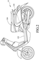
- Figure 2 exemplarily illustrates a carrier device 15 according to an embodiment
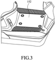
- Figures 3 and 4 further illustrate a footboard portion of the carrier device where a battery box 153 is positioned.
- an electric scooter is illustrated in Figures 2-4 , the disclosure is not limited thereto.
- the illustrated carrier device 15 that is an electric scooter has a footboard 152, a seat 154, and a storage compartment 155 under the seat 154.
- the barcode associated with the carrier identifier of the carrier device 15 is positioned at a position under the seat 154 or inside the storage compartment 155, but the disclosure is not limited thereto.
- a battery box 153 that can receive at least one battery device 12 (for example, two battery devices 12 as illustrated) is positioned in a space 150 under the footboard 152 of the carrier device 15.
- the battery box 153 may be driven by a motor (not shown) to elevate from the space 150 to reveal the battery device (s) 12, or to descend into the space 150 to conceal the battery device (s) 12.
- the footboard 152 and the battery box 153 are interlocked, such that the footboard 152 opens up the space 150 as the battery box 153 is elevated, and that the footboard 152 closes and covers the space 150 as the battery box 153 descends. In this way, it is easy to take out a battery device 12 from the carrier device 15 when the battery device 12 needs to be replaced or recharged.
- the battery device(s) 12 is/are configured to be installed in the battery box 153 to provide electrical power to the carrier device 15. However, only battery device (s) 12 bound to the carrier device 15 is/are permitted to provide electrical power to the carrier device 15. Specifically, each time a battery device 12 is installed in the battery box 153, a vehicle control unit (VCU) 151 (see Figure 1 ) of the carrier device 15 determines whether the stored data of the battery device 12 includes the carrier identifier of the carrier device 15 (the carrier identifier may be stored in the VCU 151 in advance during the manufacture of the carrier device 15). If so, the VCU 151 instructs the battery device 12 to provide electrical power to a power supply unit (not shown) fixed in the carrier device 15. If not, the VCU 151 would not instruct the battery device 12 to provide electrical power to the power supply unit of the carrier device 15, and the carrier device 15 cannot receive any electrical power from the battery device 12.
- VCU vehicle control unit
- a method for battery binding may be implemented by the system 1 illustrated in Figure 1 .
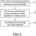
- Figure 5 exemplarily illustrates a first example of the method according to an embodiment. Referring to Figure 5 , the illustrated method includes steps 51-53. With the method, a battery device 12 can be easily and rapidly bound to a designated carrier device 15 through operation of a service end electronic device 11.
- the service end electronic device 11 obtains a carrier identifier corresponding to a carrier device 15, and stores the carrier identifier in memory (now shown in Figure 1 ) of the service end electronic device 11.
- the carrier identifier may be obtained through, for example, scanning a barcode on the carrier device 15.
- step 52 the service end electronic device 11 sends the carrier identifier to a battery device 12 through the NFC module 111.
- step 53 the battery device 12 stores the carrier identifier received from the service end electronic device 11 in memory (not shown in Figure 1 ) of the battery device 12.
- the battery device 12 is thus bound to the carrier device 15. That is, the battery device 12 is now permitted to provide electrical power to the carrier device 15.
- the service end electronic device 11 also obtains and stores a battery identifier of the battery device 12 in step 51, and sends the battery identifier along with the carrier identifier to the battery device 12 in step 52.
- the battery identifier may be obtained through, for example, scanning a barcode on the battery device 12 or through communication with the battery device 12 via near-field communication.
- Figure 6 exemplarily illustrates a second example of the method for battery binding according to an embodiment.
- the illustrated method is an augmentation of the method illustrated in Figure 5 and includes steps 61-69.
- the service end electronic device 11 communicates with a battery device 12 via near-field communication, and receives battery information from the battery device 12 that includes the state of health (SoH) of the battery device 12.
- the battery information may further include other information of the battery device 12, such as power consumption of battery discharge, remain capacity, capacity of full charge, voltage of the battery, charge/discharge current, cycle count of charge state, charging time, identifier number of the battery, software serial number of battery, and/or hardware serial number of battery.
- SoH is a ratio (in percentage) of a current, actual battery capacity of the battery device 12 to the specified battery capacity of the battery device 12 at the time of manufacture.
- a SoH of 100% means that the health condition of the battery device 12 meets its specification at the time of manufacture. Ideally, the SoH of the battery device 12 would be 100% at the time of manufacture, but the SoH may decline over time with use.
- the service end electronic device 11 compares the SoH of the battery device 12 with a predetermined threshold, and determines whether the relationship between the SoH of the battery device 12 and the predetermined threshold meets a predetermined condition. If so, the process proceeds to step 63; otherwise, the process ends.
- the predetermined condition may be, for example, the SoH of the battery device 12 being greater than the predetermined threshold. As another example, the predetermined condition may be the SoH of the battery device 12 being not less than the predetermined threshold.
- An example of the predetermined threshold is 80%.
- step 63 the service end electronic device 11 obtains a carrier identifier corresponding to a carrier device 15, and stores the carrier identifier in the memory of the service end electronic device 11.
- step 64 the service end electronic device 11 obtains a battery identifier of the battery device 12, and stores the battery identifier in the memory of the service end electronic device 11.
- step 65 the service end electronic device 11 sends the carrier identifier to the battery device 12 through the NFC module 111. In a further embodiment, the service end electronic device 11 sends the battery identifier of the battery device 12 along with the carrier identifier to the battery device 12.
- the battery device 12 stores the carrier identifier received from the service end electronic device 11 in the memory of the battery device 12, and is thus bound to the carrier device 15. In a further embodiment, the battery device 12 also stores the battery identifier received from the service end electronic device 11.
- steps 67-69 relate to data management at the server side and are optional.
- the service end electronic device 11 obtains a user identifier corresponding to a user of the carrier device 15, and stores the user identifier in the memory of the service end electronic device 11.
- the service end electronic device 11 is installed with the first application program, and is configured to obtain the user identifier through scanning a barcode associated with the user identifier and displayed on the user end electronic device 14 of the user by executing the first application program.
- the user end electronic device 14 is installed with a second application program downloaded from the cloud server 13 over the communication network 10, and is configured to display the barcode associated with the user identifier after log-in of the user to the second application program.
- a first-time log-in of the user to the second application program requires the user to complete a registration procedure, including inputting personal information to a registration webpage provided by the second application program, the personal information including information about, for example, a vehicle license, a driver's license, a name, an address and/or a contact number.
- the barcode associated with the user identifier may be generated dynamically each time the user logs in, with a limited effective time for the sake of security. That is, the barcode generated each time the user logs in to the second application program is different, and is effective only for a limited time (e.g., one hour) before it expires.
- the barcode may be a 1D barcode or a 2D barcode (e.g., a QR code).
- step 68 the service end electronic device 11 sends the carrier identifier of the carrier device 15, the battery identifier of the battery device 12 and the user identifier of the user of the carrier device 15 to the cloud server 13 over the communication network 10.
- the cloud server 13 receives the carrier identifier, the battery identifier and the user identifier from the service end electronic device 11, and stores the carrier identifier, the battery identifier and the user identifier as an associated (interrelated) group.
- the interrelationship of the carrier identifier, the battery identifier and the user identifier is specified in a lookup table stored in the cloud server 13.
- the battery device 12 is bound to the carrier device 15 and the user corresponding to the user identifier at the side of the cloud server 13.
- the service end electronic device 11 may use the battery identifier of the battery device 12 to inquire the identity of the owner/user of the battery device 12 through communication with the cloud server 13.
- the service end electronic device 11 may also use the battery identifier of the battery device 12 to inquire which carrier device 15 is allowed to use the battery device 12 through communication with the cloud server 13.
- the cloud server 13 may send a storage complete signal to the service end electronic device 11 after storing the carrier identifier, the battery identifier and the user identifier, and the service end electronic device 11 may delete the carrier identifier, the battery identifier and the user identifier stored therein in response to receiving the storage complete signal.
- the method disclosed in Figure 6 is beneficial in that the SoH examination performed in steps 61 and 62 prevents binding of an unhealthy battery device. That is, an EV owner/user is prevented from buying or renting an unhealthy or faulty battery device from the vendor.
- step 64 may be performed before step 63, and step 67 may be performed at any time as long as it is performed before step 68.
- step 67 is omitted, and only the carrier identifier and the battery identifier are sent to and stored in the cloud server 13 in steps 68 and 69.
- step 64 is omitted.
Landscapes
- Engineering & Computer Science (AREA)
- Manufacturing & Machinery (AREA)
- Chemical & Material Sciences (AREA)
- Chemical Kinetics & Catalysis (AREA)
- Electrochemistry (AREA)
- General Chemical & Material Sciences (AREA)
- Computer Networks & Wireless Communication (AREA)
- Signal Processing (AREA)
- Physics & Mathematics (AREA)
- Electromagnetism (AREA)
- Theoretical Computer Science (AREA)
- General Physics & Mathematics (AREA)
- Transportation (AREA)
- Mechanical Engineering (AREA)
- Power Engineering (AREA)
- Artificial Intelligence (AREA)
- Toxicology (AREA)
- General Health & Medical Sciences (AREA)
- Computer Vision & Pattern Recognition (AREA)
- Health & Medical Sciences (AREA)
- Microelectronics & Electronic Packaging (AREA)
- General Engineering & Computer Science (AREA)
- Charge And Discharge Circuits For Batteries Or The Like (AREA)
- Management, Administration, Business Operations System, And Electronic Commerce (AREA)
- Cell Separators (AREA)
- Secondary Cells (AREA)
Description
- The disclosure relates to management of battery devices, and more particularly to techniques for binding battery devices to carrier devices.
- With people's growing environmental awareness, electric vehicles (EVs) have been developed and are gaining public attention. Conventional electric vehicles use rechargeable and removable batteries installed therein as a source of electrical power. EV owners may purchase or rent the batteries for their use. Since the batteries need to be recharged, they have to be brought to, for example, a charging station from time to time. However, multiple batteries belonging to different owners may be simultaneously present at a charging station, so an EV owner may possibly retrieve a wrong battery (i.e., a battery that belongs to somebody else) when the charging process is finished. A mechanism is needed against such potential mistake.
EP 2 489 093 A1 andFR 2 665 559 A1 - Therefore, the present disclosure aims at providing a secure and effective solution for binding batteries to carriers such that a battery can only be used by designated carrier (s). That is, the battery would not provide electrical power to any other carrier. In this way, rights to use the batteries that owners of the carriers bought or rented can be protected.
- An object of the disclosure is to provide a method and a system for battery binding that can alleviate at least one of the drawbacks of the prior art.
- According to the disclosure, the method is to be implemented by an electronic device. The method includes steps of: obtaining a carrier identifier corresponding to a carrier device; and sending the carrier identifier to a battery device via near-field communication for storage in the battery device.
- According to the disclosure, the system includes a carrier device and a battery device configured to be installed in the carrier device to provide electrical power to the carrier device. The system further includes an electronic device capable of communication with the battery device. The electronic device is configured to obtain, from the carrier device, a carrier identifier corresponding to the carrier device. The electronic device is further configured to send the carrier identifier to the battery device via near-field communication for storage in the battery device.
- Other features and advantages of the disclosure will become apparent in the following detailed description of the embodiment (s) with reference to the accompanying drawings, of which:
-
Figure 1 is a block diagram which exemplarily illustrates a system for battery binding according to an embodiment; -
Figure 2 exemplarily illustrates a carrier device according to an embodiment; -
Figure 3 exemplarily illustrates a footboard of a carrier device according to an embodiment; -
Figure 4 exemplarily illustrates a battery box of a carrier device according to an embodiment; -
Figure 5 is a flow chart which exemplarily illustrates a first example of a method for battery binding according to an embodiment; and -
Figure 6 is a flow chart which exemplarily illustrates a second example of a method for battery binding according to an embodiment. - Before the disclosure is described in greater detail, it should be noted that where considered appropriate, reference numerals or terminal portions of reference numerals have been repeated among the figures to indicate corresponding or analogous elements, which may optionally have similar characteristics.
-
Figure 1 is a block diagram which exemplarily illustrates asystem 1 for battery binding according to an embodiment. Referring toFigure 1 , thesystem 1 includes a service endelectronic device 11, at least onebattery device 12, acloud server 13, a user endelectronic device 14 and at least onecarrier device 15. The service endelectronic device 11 and the user endelectronic device 14 are configured to communicate with thecloud server 13 over a communication network 10 (e.g., the Internet) . In an embodiment, the service endelectronic device 11 may be a mobile device of an EV vendor, and the user endelectronic device 14 may be a mobile device of an owner/user of one of the carrier device(s) 15. - According to an embodiment, each of the service end
electronic device 11 and the battery device (s) 12 includes a near-field communication (NFC)module electronic device 11 may communicate with the battery device (s) 12 via near-field communication. According to an embodiment, each of the battery device (s) 12 may further include a controller 122 electrically coupled to theNFC module 121. Each of the battery device (s) 12 may be a removable and rechargeable battery configured to be installed in one of the carrier device (s) 15 to provide electrical power thereto. Each of the carrier device(s) 15 may be a battery electric vehicle (BEV) or a hybrid electric vehicle (hybrid EV) that is a motorcycle, an automobile, a bus or the like. - According to an embodiment, each of the battery device(s) 12 has a unique battery identifier. Before being delivered to a vendor, a barcode associated with the battery identifier of the
battery device 12 may be positioned on the battery device 12 (e.g., on a top portion of the battery device 12), such that the battery identifier may be obtained through the barcode. For example, in an embodiment, the service endelectronic device 11 may obtain the battery identifier of abattery device 12 by scanning the barcode on thebattery device 12 through a first application program installed in the service endelectronic device 11 after downloading the same from thecloud server 13 over thecommunication network 10. The barcode may be a one-dimensional (1D) barcode or a two-dimensional (2D) barcode (e.g., a Quick Response code (QR code)). The battery identifier of thebattery device 12 may also be stored in thebattery device 12, such that the battery identifier may be obtained through data communication with thebattery device 12. For example, in an embodiment, the service endelectronic device 11 may obtain the battery identifier of abattery device 12 by communicating with thebattery device 12 via near-field communication through theNFC modules - According to an embodiment, each of the carrier device(s) 15 has a unique carrier identifier. According to an embodiment, before being delivered to a vendor, a barcode associated with the carrier identifier of the
carrier device 15 may be positioned on thecarrier device 15, such that the carrier identifier may be obtained through the barcode. For example, in an embodiment, the service endelectronic device 11 may obtain the carrier identifier of acarrier device 15 by scanning the barcode on thecarrier device 15 through the first application program installed in the service endelectronic device 11. The barcode may be a 1D barcode or a 2D barcode (e.g., a QR code). -
Figure 2 exemplarily illustrates acarrier device 15 according to an embodiment, andFigures 3 and4 further illustrate a footboard portion of the carrier device where abattery box 153 is positioned. Although an electric scooter is illustrated inFigures 2-4 , the disclosure is not limited thereto. - Referring to
Figure 2 , the illustratedcarrier device 15 that is an electric scooter has afootboard 152, aseat 154, and astorage compartment 155 under theseat 154. In an embodiment, the barcode associated with the carrier identifier of thecarrier device 15 is positioned at a position under theseat 154 or inside thestorage compartment 155, but the disclosure is not limited thereto. - Referring to
Figures 3 and4 , according to an embodiment, abattery box 153 that can receive at least one battery device 12 (for example, twobattery devices 12 as illustrated) is positioned in aspace 150 under thefootboard 152 of thecarrier device 15. Thebattery box 153 may be driven by a motor (not shown) to elevate from thespace 150 to reveal the battery device (s) 12, or to descend into thespace 150 to conceal the battery device (s) 12. According to an embodiment, thefootboard 152 and thebattery box 153 are interlocked, such that thefootboard 152 opens up thespace 150 as thebattery box 153 is elevated, and that thefootboard 152 closes and covers thespace 150 as thebattery box 153 descends. In this way, it is easy to take out abattery device 12 from thecarrier device 15 when thebattery device 12 needs to be replaced or recharged. - The battery device(s) 12 is/are configured to be installed in the
battery box 153 to provide electrical power to thecarrier device 15. However, only battery device (s) 12 bound to thecarrier device 15 is/are permitted to provide electrical power to thecarrier device 15. Specifically, each time abattery device 12 is installed in thebattery box 153, a vehicle control unit (VCU) 151 (seeFigure 1 ) of thecarrier device 15 determines whether the stored data of thebattery device 12 includes the carrier identifier of the carrier device 15 (the carrier identifier may be stored in theVCU 151 in advance during the manufacture of the carrier device 15). If so, the VCU 151 instructs thebattery device 12 to provide electrical power to a power supply unit (not shown) fixed in thecarrier device 15. If not, the VCU 151 would not instruct thebattery device 12 to provide electrical power to the power supply unit of thecarrier device 15, and thecarrier device 15 cannot receive any electrical power from thebattery device 12. - A method for battery binding may be implemented by the
system 1 illustrated inFigure 1 .Figure 5 exemplarily illustrates a first example of the method according to an embodiment. Referring toFigure 5 , the illustrated method includes steps 51-53. With the method, abattery device 12 can be easily and rapidly bound to a designatedcarrier device 15 through operation of a service endelectronic device 11. - In
step 51, the service endelectronic device 11 obtains a carrier identifier corresponding to acarrier device 15, and stores the carrier identifier in memory (now shown inFigure 1 ) of the service endelectronic device 11. The carrier identifier may be obtained through, for example, scanning a barcode on thecarrier device 15. - In
step 52, the service endelectronic device 11 sends the carrier identifier to abattery device 12 through theNFC module 111. - In
step 53, thebattery device 12 stores the carrier identifier received from the service endelectronic device 11 in memory (not shown inFigure 1 ) of thebattery device 12. Thebattery device 12 is thus bound to thecarrier device 15. That is, thebattery device 12 is now permitted to provide electrical power to thecarrier device 15. - In a further embodiment, the service end
electronic device 11 also obtains and stores a battery identifier of thebattery device 12 instep 51, and sends the battery identifier along with the carrier identifier to thebattery device 12 instep 52. The battery identifier may be obtained through, for example, scanning a barcode on thebattery device 12 or through communication with thebattery device 12 via near-field communication. -
Figure 6 exemplarily illustrates a second example of the method for battery binding according to an embodiment. Referring toFigure 6 , the illustrated method is an augmentation of the method illustrated inFigure 5 and includes steps 61-69. - In
step 61, the service endelectronic device 11 communicates with abattery device 12 via near-field communication, and receives battery information from thebattery device 12 that includes the state of health (SoH) of thebattery device 12. The battery information may further include other information of thebattery device 12, such as power consumption of battery discharge, remain capacity, capacity of full charge, voltage of the battery, charge/discharge current, cycle count of charge state, charging time, identifier number of the battery, software serial number of battery, and/or hardware serial number of battery. SoH is a ratio (in percentage) of a current, actual battery capacity of thebattery device 12 to the specified battery capacity of thebattery device 12 at the time of manufacture. A SoH of 100% means that the health condition of thebattery device 12 meets its specification at the time of manufacture. Ideally, the SoH of thebattery device 12 would be 100% at the time of manufacture, but the SoH may decline over time with use. - In
step 62, the service endelectronic device 11 compares the SoH of thebattery device 12 with a predetermined threshold, and determines whether the relationship between the SoH of thebattery device 12 and the predetermined threshold meets a predetermined condition. If so, the process proceeds to step 63; otherwise, the process ends. The predetermined condition may be, for example, the SoH of thebattery device 12 being greater than the predetermined threshold. As another example, the predetermined condition may be the SoH of thebattery device 12 being not less than the predetermined threshold. An example of the predetermined threshold is 80%. - In
step 63, the service endelectronic device 11 obtains a carrier identifier corresponding to acarrier device 15, and stores the carrier identifier in the memory of the service endelectronic device 11. - In
step 64, the service endelectronic device 11 obtains a battery identifier of thebattery device 12, and stores the battery identifier in the memory of the service endelectronic device 11. - In
step 65, the service endelectronic device 11 sends the carrier identifier to thebattery device 12 through theNFC module 111. In a further embodiment, the service endelectronic device 11 sends the battery identifier of thebattery device 12 along with the carrier identifier to thebattery device 12. - In
step 66, thebattery device 12 stores the carrier identifier received from the service endelectronic device 11 in the memory of thebattery device 12, and is thus bound to thecarrier device 15. In a further embodiment, thebattery device 12 also stores the battery identifier received from the service endelectronic device 11. - The following steps 67-69 relate to data management at the server side and are optional.
- In
step 67, the service endelectronic device 11 obtains a user identifier corresponding to a user of thecarrier device 15, and stores the user identifier in the memory of the service endelectronic device 11. According to an embodiment, the service endelectronic device 11 is installed with the first application program, and is configured to obtain the user identifier through scanning a barcode associated with the user identifier and displayed on the user endelectronic device 14 of the user by executing the first application program. According to an embodiment, the user endelectronic device 14 is installed with a second application program downloaded from thecloud server 13 over thecommunication network 10, and is configured to display the barcode associated with the user identifier after log-in of the user to the second application program. A first-time log-in of the user to the second application program requires the user to complete a registration procedure, including inputting personal information to a registration webpage provided by the second application program, the personal information including information about, for example, a vehicle license, a driver's license, a name, an address and/or a contact number. The barcode associated with the user identifier may be generated dynamically each time the user logs in, with a limited effective time for the sake of security. That is, the barcode generated each time the user logs in to the second application program is different, and is effective only for a limited time (e.g., one hour) before it expires. According to an embodiment, the barcode may be a 1D barcode or a 2D barcode (e.g., a QR code). - In
step 68, the service endelectronic device 11 sends the carrier identifier of thecarrier device 15, the battery identifier of thebattery device 12 and the user identifier of the user of thecarrier device 15 to thecloud server 13 over thecommunication network 10. - In
step 69, thecloud server 13 receives the carrier identifier, the battery identifier and the user identifier from the service endelectronic device 11, and stores the carrier identifier, the battery identifier and the user identifier as an associated (interrelated) group. In an embodiment, the interrelationship of the carrier identifier, the battery identifier and the user identifier is specified in a lookup table stored in thecloud server 13. In this case, thebattery device 12 is bound to thecarrier device 15 and the user corresponding to the user identifier at the side of thecloud server 13. Afterwards, the service endelectronic device 11 may use the battery identifier of thebattery device 12 to inquire the identity of the owner/user of thebattery device 12 through communication with thecloud server 13. The service endelectronic device 11 may also use the battery identifier of thebattery device 12 to inquire whichcarrier device 15 is allowed to use thebattery device 12 through communication with thecloud server 13. Thecloud server 13 may send a storage complete signal to the service endelectronic device 11 after storing the carrier identifier, the battery identifier and the user identifier, and the service endelectronic device 11 may delete the carrier identifier, the battery identifier and the user identifier stored therein in response to receiving the storage complete signal. - In addition to easily and rapidly binding a
battery device 12 to acarrier device 15, the method disclosed inFigure 6 is beneficial in that the SoH examination performed insteps - One of ordinary skill in the relevant art would appreciate that it is not necessary for steps 61-69 to be performed in exactly the order illustrated in
Figure 6 . Specifically, step 64 may be performed beforestep 63, and step 67 may be performed at any time as long as it is performed beforestep 68. - Other alterations may be made to the method as well. For example, in an embodiment,
step 67 is omitted, and only the carrier identifier and the battery identifier are sent to and stored in thecloud server 13 insteps electronic device 11 receives from thebattery device 12 instep 61 includes the battery identifier of thebattery device 12,step 64 is omitted.
Claims (17)
- A method for battery binding, the method being implemented by a service end electronic device (11) and characterized by steps of:obtaining, through a barcode at one of a position under a seat (154) of the carrier device (15) and a position inside a storage compartment (155) of the carrier device (15), a carrier identifier corresponding to a carrier device (15) that is capable of being electrically powered; andsending the carrier identifier to a battery device (12), in which a battery identifier is stored, via near-field communication for storage in the battery device (12).
- The method of claim 1, characterized in that the barcode is a Quick Response code.
- The method of claim 1, further characterized by steps of:acquiring battery information from the battery device (12) via near-field communication, the battery information including state of health of the battery device (12); anddetermining if the state of health of the battery device (12) is greater than a predetermined threshold;wherein the step of obtaining a carrier identifier and the step of sending the carrier identifier are implemented when it is determined that the state of health is greater than the predetermined threshold.
- The method of claim 3, further characterized by a step of:when it is determined that the state of health is greater than the predetermined threshold, obtaining the battery identifier corresponding to the battery device (12) ;wherein the step of sending the carrier identifier includes sending the battery identifier thus obtained along with the carrier identifier to the battery device (12) via near-field communication for storage of at least the carrier identifier in the battery device (12).
- The method of claim 4, characterized in that the battery identifier is obtained from a storage of the battery device (12) via near-field communication or obtained through a barcode that is a Quick Response code located on a top portion of the battery device (12).
- The method of claim 1, characterized in that the battery device (12) stores both the battery identifier and the carrier identifier after completion of the step of sending the carrier identifier.
- The method of claim 1, further characterized by a step of:
obtaining a user identifier corresponding to a user of the carrier device (15) in order to bind the battery device (12) to the user. - The method of claim 7, characterized in that the user identifier is obtained through a barcode that is a Quick Response code displayed on a user end electronic device (14) of the user.
- The method of claim 7, characterized by a step of:
sending, to a cloud server (13) in communication with the service end electronic device (11) over a communication network (10), at least one of the carrier identifier, the user identifier and the battery identifier of the battery device (12) over the communication network (10) for storage in the cloud server (13), wherein the communication network is the Internet. - A system (1) for battery binding, the system comprising:a carrier device (15) including a seat (154) and a storage compartment (155);a battery device (12) configured to be installed in said carrier device (15); anda service end electronic device (11) configured to communicate with said battery device (12);said system being characterized in that:said carrier device (15) has a barcode at one of a position under said seat (154) and a position inside said storage compartment (155), the barcode being associated with a carrier identifier corresponding to said carrier device (15); andsaid service end electronic device (11) is configured to obtain, from said carrier device (15), the carrier identifier through the barcode, and to send the carrier identifier to said battery device (12) via near-field communication for storage in said battery device (12).
- The system (1) of claim 10, characterized in that said service end electronic device (11) is further configured to:acquire battery information from said battery device (12) via near-field communication, the battery information including state of health of said battery device (12); anddetermine if the state of health of said battery device (12) is greater than a predetermined threshold;wherein said service end electronic device (11) is to obtain the carrier identifier and send the carrier identifier only when it is determined that the state of health is greater than the predetermined threshold.
- The system (1) of claim 10, characterized in that the barcode is a Quick Response code.
- The system (1) of claim 10, characterized in that said service end electronic device (11) is further configured to:acquire battery information from said battery device (12) via near-field communication, the battery information including state of health of said battery device (12); anddetermine if the state of health of said battery device (12) is greater than a predetermined threshold;when it is determined that the state of health is greater than the predetermined threshold, obtain a battery identifier of said battery device (12) from said battery device (12);wherein said service end electronic device (11) is to obtain the carrier identifier and send the carrier identifier only when it is determined that the state of health is greater than the predetermined threshold, said service end electronic device (11) sending the battery identifier along with the carrier identifier.
- The system (1) of claim 13, characterized in that said battery device (12) has a barcode associated with the battery identifier that is a Quick Response code located on a top portion of said battery device (12), and that said service end electronic device (11) is configured to obtain the battery identifier through the barcode.
- The system (1) of claim 13, characterized in that said service end electronic device (11) includes a near-field communication module (111), that said battery device (12) includes a near-field communication module (121), and that said near-field communication module (111) of said service end electronic device (11) is configured to communicate with said near-field communication module (121) of said battery device (12) in order to send the carrier identifier and the battery identifier to said battery device (12).
- The system (1) of claim 10, characterized in that said battery device (12) stores a battery identifier.
- The system (1) of claim 10, further characterized by:a cloud server (13) configured to communicate with said service end electronic device (11) over a communication network (10) which is the Internet; anda user end electronic device (14) configured to communicate with said cloud server (13) over the communication network (10),wherein said service end electronic device (11) is installed with a first application program, and is configured to obtain the carrier identifier by executing the first application program,wherein said user end electronic device (14) is installed with a second application program, and is configured to display a barcode associated with a user identifier corresponding to a user of said carrier device (15) after log-in of the user to the second application program, the barcode that is associated with the user identifier being a Quick Response code,wherein said service end electronic device (11) is further configured to:obtain the user identifier through the barcode displayed on said user end electronic device (14); andsend the carrier identifier, the user identifier and a battery identifier of said battery device (12) to said cloud server (13) over the communication network (10) for storage in said cloud server (13) as an associated group.
Applications Claiming Priority (1)
| Application Number | Priority Date | Filing Date | Title |
|---|---|---|---|
| TW107108023A TWI705379B (en) | 2018-03-09 | 2018-03-09 | Battery binding method and system |
Publications (2)
| Publication Number | Publication Date |
|---|---|
| EP3536545A1 EP3536545A1 (en) | 2019-09-11 |
| EP3536545B1 true EP3536545B1 (en) | 2022-03-16 |
Family
ID=65324284
Family Applications (1)
| Application Number | Title | Priority Date | Filing Date |
|---|---|---|---|
| EP19155603.4A Active EP3536545B1 (en) | 2018-03-09 | 2019-02-05 | Method and system for battery binding |
Country Status (7)
| Country | Link |
|---|---|
| US (1) | US11094971B2 (en) |
| EP (1) | EP3536545B1 (en) |
| JP (1) | JP6777778B2 (en) |
| CN (1) | CN110248342B (en) |
| CA (1) | CA3033601A1 (en) |
| PH (1) | PH12019000120B1 (en) |
| TW (1) | TWI705379B (en) |
Families Citing this family (9)
| Publication number | Priority date | Publication date | Assignee | Title |
|---|---|---|---|---|
| TWI679549B (en) * | 2018-03-13 | 2019-12-11 | 光陽工業股份有限公司 | Battery binding method and system |
| US11661029B2 (en) * | 2020-06-24 | 2023-05-30 | TWS Technology(Guangzhou) Limited | Authentication between battery management system (BMS) and battery host platform |
| KR102340149B1 (en) | 2020-08-14 | 2021-12-16 | 주식회사 현대케피코 | Communication device and communication system including the same |
| KR102256807B1 (en) * | 2020-08-18 | 2021-05-28 | (주)그린파워 | Wireless Charging System |
| CN113619435B (en) * | 2021-07-22 | 2023-09-01 | 广东劲天科技有限公司 | Cross-platform charging method, terminal and storage device |
| CN114429146B (en) * | 2021-12-27 | 2023-11-03 | 华人运通(江苏)技术有限公司 | Error-proofing control system for battery production operation |
| CN115458822A (en) * | 2022-10-09 | 2022-12-09 | 四川长虹网络科技有限责任公司 | Battery control system and method |
| JP2024090611A (en) * | 2022-12-23 | 2024-07-04 | ブリヂストンサイクル株式会社 | Method for authenticating a battery for an electric vehicle and an electric vehicle using the same |
| TWI902270B (en) * | 2023-05-31 | 2025-10-21 | 英屬開曼群島商睿能創意公司 | Battery-swappable electric vehicle, swappable battery, and battery binding method thereof |
Family Cites Families (27)
| Publication number | Priority date | Publication date | Assignee | Title |
|---|---|---|---|---|
| FR2665559B3 (en) * | 1990-08-01 | 1992-12-11 | Travaux Electriques Ste Gle | ELECTRIC VEHICLE MANAGEMENT SYSTEM WITH ACCUMULATOR BATTERY, VEHICLE CASE AND BATTERY CASE OF SUCH A SYSTEM, AND VEHICLE COMPRISING SUCH A VEHICLE CASE. |
| TWI307050B (en) * | 2005-08-16 | 2009-03-01 | Ind Tech Res Inst | Electric vehicle management system and method |
| KR20090033451A (en) * | 2006-06-30 | 2009-04-03 | 사임베트 코퍼레이션 | Thin Film Battery Recharge System and Method |
| US7551088B2 (en) * | 2007-04-12 | 2009-06-23 | Findlay W David | Electronic vehicle tag |
| IT1395947B1 (en) * | 2009-10-15 | 2012-11-02 | Meta System Spa | ELECTRIC BATTERY FOR VEHICLES |
| WO2011123808A2 (en) * | 2010-04-02 | 2011-10-06 | Boston-Power, Inc. | Battery pack safety techniques |
| JP5652748B2 (en) * | 2010-12-14 | 2015-01-14 | 株式会社デンソー | Control system, communication device |
| JP5392861B2 (en) * | 2011-05-16 | 2014-01-22 | ソニー株式会社 | Power supply apparatus and method, power supply system, and program |
| JPWO2013005739A1 (en) * | 2011-07-06 | 2015-02-23 | 昭和電工株式会社 | ELECTRODE FOR LITHIUM SECONDARY BATTERY, LITHIUM SECONDARY BATTERY, AND METHOD FOR PRODUCING ELECTRODE FOR LITHIUM SECONDARY BATTERY |
| WO2013080211A1 (en) * | 2011-12-02 | 2013-06-06 | Better Place GmbH | Battery selection system and method |
| TWI499534B (en) * | 2012-03-06 | 2015-09-11 | Awise Fiber Technology Co Ltd | Bicycle frame of carbon fiber and bicycle including the same |
| CN102991612B (en) * | 2012-12-05 | 2015-06-17 | 中路股份有限公司 | Intelligent anti-theft system of electric bicycle and implementation method |
| JP5886333B2 (en) * | 2014-02-04 | 2016-03-16 | ソフトバンク株式会社 | Power supply system |
| US9287718B2 (en) * | 2013-03-01 | 2016-03-15 | Nokia Technologies Oy | Method, apparatus, and computer program product for foreign object detection parameter and charging data communication with wireless charging capable battery pack |
| CN104954399B (en) * | 2014-03-27 | 2018-06-19 | 正文科技股份有限公司 | Method for binding mobile carrier and intelligent device and binding system thereof |
| ES2914287T3 (en) * | 2014-09-04 | 2022-06-08 | Gogoro Inc | Charging module for a bidirectional distribution system of electrical energy storage devices |
| US9711993B2 (en) * | 2014-11-24 | 2017-07-18 | Harman International Industries, Inc. | Opportunistic charging of an electronic device |
| JP6504246B2 (en) * | 2015-03-12 | 2019-04-24 | オムロン株式会社 | INFORMATION PROCESSING APPARATUS, CONTROL METHOD THEREOF, CONTROL PROGRAM, AND RECORDING MEDIUM |
| US20180262891A1 (en) * | 2015-06-11 | 2018-09-13 | 3M Innovative Properties Company | Electronic access control systems and methods using near-field communications, mobile devices and cloud computing |
| CN106533476B (en) * | 2015-09-14 | 2019-02-12 | 广州汽车集团股份有限公司 | Method and system for binding vehicle and vehicle terminal |
| EP3374231B1 (en) * | 2015-11-13 | 2025-07-02 | Harman International Industries, Incorporated | User interface for in-vehicle system |
| JP6479649B2 (en) * | 2015-12-28 | 2019-03-06 | 日本電信電話株式会社 | Mobile battery replacement service system, mobile battery replacement method |
| JP6675075B2 (en) * | 2016-01-25 | 2020-04-01 | パナソニックIpマネジメント株式会社 | Battery storage device and battery rental system |
| US10525848B2 (en) * | 2016-08-02 | 2020-01-07 | Here Global B.V. | Vehicle charging lanes |
| CN106080518B (en) * | 2016-08-11 | 2021-07-23 | 北京小米移动软件有限公司 | Electric vehicle battery, electric vehicle, system and method with anti-theft function |
| CN110914143A (en) * | 2017-06-23 | 2020-03-24 | 优步技术公司 | Electric assist bicycle |
| CN107380004B (en) * | 2017-09-07 | 2020-06-19 | 苏州易信安工业技术有限公司 | Electric vehicle battery management method, device and system |
-
2018
- 2018-03-09 TW TW107108023A patent/TWI705379B/en active
-
2019
- 2019-02-05 EP EP19155603.4A patent/EP3536545B1/en active Active
- 2019-02-12 CA CA3033601A patent/CA3033601A1/en not_active Abandoned
- 2019-02-14 JP JP2019024591A patent/JP6777778B2/en active Active
- 2019-02-22 CN CN201910131424.4A patent/CN110248342B/en active Active
- 2019-03-05 PH PH1/2019/000120A patent/PH12019000120B1/en unknown
- 2019-03-07 US US16/295,963 patent/US11094971B2/en active Active
Also Published As
| Publication number | Publication date |
|---|---|
| TW201939359A (en) | 2019-10-01 |
| JP6777778B2 (en) | 2020-10-28 |
| CA3033601A1 (en) | 2019-09-09 |
| PH12019000120A1 (en) | 2019-11-11 |
| CN110248342A (en) | 2019-09-17 |
| TWI705379B (en) | 2020-09-21 |
| EP3536545A1 (en) | 2019-09-11 |
| PH12019000120B1 (en) | 2023-01-13 |
| JP2019179545A (en) | 2019-10-17 |
| US20190280344A1 (en) | 2019-09-12 |
| CN110248342B (en) | 2022-04-29 |
| US11094971B2 (en) | 2021-08-17 |
Similar Documents
| Publication | Publication Date | Title |
|---|---|---|
| EP3536545B1 (en) | Method and system for battery binding | |
| US11155179B2 (en) | Method and system for binding battery devices to carrier devices | |
| US10525845B2 (en) | Electric vehicle charging station parking spot monitoring system | |
| US10614712B2 (en) | Server and information providing method | |
| CN107301060A (en) | Method and system for remote software update to be downloaded and installed on vehicle | |
| KR20230118543A (en) | Wireless communication method and apparatus for wireless power transmission to electric vehicle | |
| CN106297043B (en) | Internet of Things-based battery rental system and method | |
| EP3536544A1 (en) | Verification method and system for battery power supply | |
| US20220024335A1 (en) | Electrical charge pattern validation | |
| WO2015028857A1 (en) | Charging system and pairing method | |
| US20190130449A1 (en) | Information providing system and server | |
| CN109849937A (en) | A kind of vehicle device accumulator charging control method and relevant device | |
| DE102022127756A1 (en) | INTELLIGENT VEHICLE SYSTEMS AND CONTROL LOGIC FOR BATTERY CHARGE CONTROL AND INFORMATION DISPLAY | |
| CN207068014U (en) | The power accumulator and its Electrical ID system of a kind of electric vehicle | |
| WO2012132404A1 (en) | Electric power supply device | |
| CN118057433A (en) | Electric vehicle management method and management system, and computer device | |
| CN110281805A (en) | The method and energy management system of the reservation supplement energy | |
| JP7136785B2 (en) | POWER SYSTEM, POWER STORAGE DEVICE, CONTROL METHOD OF POWER SYSTEM, AND MOVING OBJECT | |
| KR20190036117A (en) | Apparatus for Controlling Electric Vehicle Charging And Discharging | |
| FR2970923A1 (en) | Method for checking identity of e.g. electric vehicle at charging terminal, involves providing alert information and location of vehicle to dedicated service e.g. police force, when identifier of vehicle is in list of stolen vehicles | |
| CN107862769B (en) | Information processing method, electronic device, and computer storage medium | |
| US20250376066A1 (en) | Automatic selection of a contract certificate to facilitate electric vehicle charging | |
| DE102023127846A1 (en) | INTELLIGENT VEHICLE SYSTEMS AND CONTROL LOGIC FOR VEHICLE CHARGING USING INTELLIGENT WIRELESS CONNECTIVITY | |
| JP2025121291A (en) | Electric vehicles | |
| KR20250144434A (en) | Concept for selecting charging contracts based on charging stations |
Legal Events
| Date | Code | Title | Description |
|---|---|---|---|
| PUAI | Public reference made under article 153(3) epc to a published international application that has entered the european phase |
Free format text: ORIGINAL CODE: 0009012 |
|
| STAA | Information on the status of an ep patent application or granted ep patent |
Free format text: STATUS: THE APPLICATION HAS BEEN PUBLISHED |
|
| AK | Designated contracting states |
Kind code of ref document: A1 Designated state(s): AL AT BE BG CH CY CZ DE DK EE ES FI FR GB GR HR HU IE IS IT LI LT LU LV MC MK MT NL NO PL PT RO RS SE SI SK SM TR |
|
| AX | Request for extension of the european patent |
Extension state: BA ME |
|
| STAA | Information on the status of an ep patent application or granted ep patent |
Free format text: STATUS: REQUEST FOR EXAMINATION WAS MADE |
|
| 17P | Request for examination filed |
Effective date: 20200127 |
|
| RBV | Designated contracting states (corrected) |
Designated state(s): AL AT BE BG CH CY CZ DE DK EE ES FI FR GB GR HR HU IE IS IT LI LT LU LV MC MK MT NL NO PL PT RO RS SE SI SK SM TR |
|
| GRAP | Despatch of communication of intention to grant a patent |
Free format text: ORIGINAL CODE: EPIDOSNIGR1 |
|
| STAA | Information on the status of an ep patent application or granted ep patent |
Free format text: STATUS: GRANT OF PATENT IS INTENDED |
|
| INTG | Intention to grant announced |
Effective date: 20210927 |
|
| GRAS | Grant fee paid |
Free format text: ORIGINAL CODE: EPIDOSNIGR3 |
|
| GRAA | (expected) grant |
Free format text: ORIGINAL CODE: 0009210 |
|
| STAA | Information on the status of an ep patent application or granted ep patent |
Free format text: STATUS: THE PATENT HAS BEEN GRANTED |
|
| AK | Designated contracting states |
Kind code of ref document: B1 Designated state(s): AL AT BE BG CH CY CZ DE DK EE ES FI FR GB GR HR HU IE IS IT LI LT LU LV MC MK MT NL NO PL PT RO RS SE SI SK SM TR |
|
| REG | Reference to a national code |
Ref country code: GB Ref legal event code: FG4D |
|
| REG | Reference to a national code |
Ref country code: CH Ref legal event code: EP |
|
| REG | Reference to a national code |
Ref country code: DE Ref legal event code: R096 Ref document number: 602019012488 Country of ref document: DE |
|
| REG | Reference to a national code |
Ref country code: IE Ref legal event code: FG4D |
|
| REG | Reference to a national code |
Ref country code: AT Ref legal event code: REF Ref document number: 1475653 Country of ref document: AT Kind code of ref document: T Effective date: 20220415 |
|
| REG | Reference to a national code |
Ref country code: LT Ref legal event code: MG9D |
|
| REG | Reference to a national code |
Ref country code: NL Ref legal event code: MP Effective date: 20220316 |
|
| PG25 | Lapsed in a contracting state [announced via postgrant information from national office to epo] |
Ref country code: SE Free format text: LAPSE BECAUSE OF FAILURE TO SUBMIT A TRANSLATION OF THE DESCRIPTION OR TO PAY THE FEE WITHIN THE PRESCRIBED TIME-LIMIT Effective date: 20220316 Ref country code: RS Free format text: LAPSE BECAUSE OF FAILURE TO SUBMIT A TRANSLATION OF THE DESCRIPTION OR TO PAY THE FEE WITHIN THE PRESCRIBED TIME-LIMIT Effective date: 20220316 Ref country code: NO Free format text: LAPSE BECAUSE OF FAILURE TO SUBMIT A TRANSLATION OF THE DESCRIPTION OR TO PAY THE FEE WITHIN THE PRESCRIBED TIME-LIMIT Effective date: 20220616 Ref country code: LT Free format text: LAPSE BECAUSE OF FAILURE TO SUBMIT A TRANSLATION OF THE DESCRIPTION OR TO PAY THE FEE WITHIN THE PRESCRIBED TIME-LIMIT Effective date: 20220316 Ref country code: HR Free format text: LAPSE BECAUSE OF FAILURE TO SUBMIT A TRANSLATION OF THE DESCRIPTION OR TO PAY THE FEE WITHIN THE PRESCRIBED TIME-LIMIT Effective date: 20220316 Ref country code: BG Free format text: LAPSE BECAUSE OF FAILURE TO SUBMIT A TRANSLATION OF THE DESCRIPTION OR TO PAY THE FEE WITHIN THE PRESCRIBED TIME-LIMIT Effective date: 20220616 |
|
| REG | Reference to a national code |
Ref country code: AT Ref legal event code: MK05 Ref document number: 1475653 Country of ref document: AT Kind code of ref document: T Effective date: 20220316 |
|
| PG25 | Lapsed in a contracting state [announced via postgrant information from national office to epo] |
Ref country code: LV Free format text: LAPSE BECAUSE OF FAILURE TO SUBMIT A TRANSLATION OF THE DESCRIPTION OR TO PAY THE FEE WITHIN THE PRESCRIBED TIME-LIMIT Effective date: 20220316 Ref country code: GR Free format text: LAPSE BECAUSE OF FAILURE TO SUBMIT A TRANSLATION OF THE DESCRIPTION OR TO PAY THE FEE WITHIN THE PRESCRIBED TIME-LIMIT Effective date: 20220617 Ref country code: FI Free format text: LAPSE BECAUSE OF FAILURE TO SUBMIT A TRANSLATION OF THE DESCRIPTION OR TO PAY THE FEE WITHIN THE PRESCRIBED TIME-LIMIT Effective date: 20220316 |
|
| PG25 | Lapsed in a contracting state [announced via postgrant information from national office to epo] |
Ref country code: NL Free format text: LAPSE BECAUSE OF FAILURE TO SUBMIT A TRANSLATION OF THE DESCRIPTION OR TO PAY THE FEE WITHIN THE PRESCRIBED TIME-LIMIT Effective date: 20220316 |
|
| PG25 | Lapsed in a contracting state [announced via postgrant information from national office to epo] |
Ref country code: SM Free format text: LAPSE BECAUSE OF FAILURE TO SUBMIT A TRANSLATION OF THE DESCRIPTION OR TO PAY THE FEE WITHIN THE PRESCRIBED TIME-LIMIT Effective date: 20220316 Ref country code: SK Free format text: LAPSE BECAUSE OF FAILURE TO SUBMIT A TRANSLATION OF THE DESCRIPTION OR TO PAY THE FEE WITHIN THE PRESCRIBED TIME-LIMIT Effective date: 20220316 Ref country code: RO Free format text: LAPSE BECAUSE OF FAILURE TO SUBMIT A TRANSLATION OF THE DESCRIPTION OR TO PAY THE FEE WITHIN THE PRESCRIBED TIME-LIMIT Effective date: 20220316 Ref country code: PT Free format text: LAPSE BECAUSE OF FAILURE TO SUBMIT A TRANSLATION OF THE DESCRIPTION OR TO PAY THE FEE WITHIN THE PRESCRIBED TIME-LIMIT Effective date: 20220718 Ref country code: ES Free format text: LAPSE BECAUSE OF FAILURE TO SUBMIT A TRANSLATION OF THE DESCRIPTION OR TO PAY THE FEE WITHIN THE PRESCRIBED TIME-LIMIT Effective date: 20220316 Ref country code: EE Free format text: LAPSE BECAUSE OF FAILURE TO SUBMIT A TRANSLATION OF THE DESCRIPTION OR TO PAY THE FEE WITHIN THE PRESCRIBED TIME-LIMIT Effective date: 20220316 Ref country code: CZ Free format text: LAPSE BECAUSE OF FAILURE TO SUBMIT A TRANSLATION OF THE DESCRIPTION OR TO PAY THE FEE WITHIN THE PRESCRIBED TIME-LIMIT Effective date: 20220316 Ref country code: AT Free format text: LAPSE BECAUSE OF FAILURE TO SUBMIT A TRANSLATION OF THE DESCRIPTION OR TO PAY THE FEE WITHIN THE PRESCRIBED TIME-LIMIT Effective date: 20220316 |
|
| PG25 | Lapsed in a contracting state [announced via postgrant information from national office to epo] |
Ref country code: PL Free format text: LAPSE BECAUSE OF FAILURE TO SUBMIT A TRANSLATION OF THE DESCRIPTION OR TO PAY THE FEE WITHIN THE PRESCRIBED TIME-LIMIT Effective date: 20220316 Ref country code: IS Free format text: LAPSE BECAUSE OF FAILURE TO SUBMIT A TRANSLATION OF THE DESCRIPTION OR TO PAY THE FEE WITHIN THE PRESCRIBED TIME-LIMIT Effective date: 20220716 Ref country code: AL Free format text: LAPSE BECAUSE OF FAILURE TO SUBMIT A TRANSLATION OF THE DESCRIPTION OR TO PAY THE FEE WITHIN THE PRESCRIBED TIME-LIMIT Effective date: 20220316 |
|
| REG | Reference to a national code |
Ref country code: DE Ref legal event code: R097 Ref document number: 602019012488 Country of ref document: DE |
|
| PLBE | No opposition filed within time limit |
Free format text: ORIGINAL CODE: 0009261 |
|
| STAA | Information on the status of an ep patent application or granted ep patent |
Free format text: STATUS: NO OPPOSITION FILED WITHIN TIME LIMIT |
|
| PG25 | Lapsed in a contracting state [announced via postgrant information from national office to epo] |
Ref country code: DK Free format text: LAPSE BECAUSE OF FAILURE TO SUBMIT A TRANSLATION OF THE DESCRIPTION OR TO PAY THE FEE WITHIN THE PRESCRIBED TIME-LIMIT Effective date: 20220316 |
|
| 26N | No opposition filed |
Effective date: 20221219 |
|
| PG25 | Lapsed in a contracting state [announced via postgrant information from national office to epo] |
Ref country code: SI Free format text: LAPSE BECAUSE OF FAILURE TO SUBMIT A TRANSLATION OF THE DESCRIPTION OR TO PAY THE FEE WITHIN THE PRESCRIBED TIME-LIMIT Effective date: 20220316 |
|
| REG | Reference to a national code |
Ref country code: DE Ref legal event code: R119 Ref document number: 602019012488 Country of ref document: DE |
|
| PG25 | Lapsed in a contracting state [announced via postgrant information from national office to epo] |
Ref country code: MC Free format text: LAPSE BECAUSE OF FAILURE TO SUBMIT A TRANSLATION OF THE DESCRIPTION OR TO PAY THE FEE WITHIN THE PRESCRIBED TIME-LIMIT Effective date: 20220316 |
|
| REG | Reference to a national code |
Ref country code: CH Ref legal event code: PL |
|
| REG | Reference to a national code |
Ref country code: BE Ref legal event code: MM Effective date: 20230228 |
|
| GBPC | Gb: european patent ceased through non-payment of renewal fee |
Effective date: 20230205 |
|
| PG25 | Lapsed in a contracting state [announced via postgrant information from national office to epo] |
Ref country code: LU Free format text: LAPSE BECAUSE OF NON-PAYMENT OF DUE FEES Effective date: 20230205 Ref country code: LI Free format text: LAPSE BECAUSE OF NON-PAYMENT OF DUE FEES Effective date: 20230228 Ref country code: CH Free format text: LAPSE BECAUSE OF NON-PAYMENT OF DUE FEES Effective date: 20230228 |
|
| REG | Reference to a national code |
Ref country code: IE Ref legal event code: MM4A |
|
| PG25 | Lapsed in a contracting state [announced via postgrant information from national office to epo] |
Ref country code: GB Free format text: LAPSE BECAUSE OF NON-PAYMENT OF DUE FEES Effective date: 20230205 |
|
| PG25 | Lapsed in a contracting state [announced via postgrant information from national office to epo] |
Ref country code: IE Free format text: LAPSE BECAUSE OF NON-PAYMENT OF DUE FEES Effective date: 20230205 Ref country code: GB Free format text: LAPSE BECAUSE OF NON-PAYMENT OF DUE FEES Effective date: 20230205 Ref country code: FR Free format text: LAPSE BECAUSE OF NON-PAYMENT OF DUE FEES Effective date: 20230228 Ref country code: DE Free format text: LAPSE BECAUSE OF NON-PAYMENT OF DUE FEES Effective date: 20230901 |
|
| PG25 | Lapsed in a contracting state [announced via postgrant information from national office to epo] |
Ref country code: BE Free format text: LAPSE BECAUSE OF NON-PAYMENT OF DUE FEES Effective date: 20230228 |
|
| PG25 | Lapsed in a contracting state [announced via postgrant information from national office to epo] |
Ref country code: CY Free format text: LAPSE BECAUSE OF FAILURE TO SUBMIT A TRANSLATION OF THE DESCRIPTION OR TO PAY THE FEE WITHIN THE PRESCRIBED TIME-LIMIT; INVALID AB INITIO Effective date: 20190205 |
|
| PG25 | Lapsed in a contracting state [announced via postgrant information from national office to epo] |
Ref country code: HU Free format text: LAPSE BECAUSE OF FAILURE TO SUBMIT A TRANSLATION OF THE DESCRIPTION OR TO PAY THE FEE WITHIN THE PRESCRIBED TIME-LIMIT; INVALID AB INITIO Effective date: 20190205 |
|
| PG25 | Lapsed in a contracting state [announced via postgrant information from national office to epo] |
Ref country code: TR Free format text: LAPSE BECAUSE OF FAILURE TO SUBMIT A TRANSLATION OF THE DESCRIPTION OR TO PAY THE FEE WITHIN THE PRESCRIBED TIME-LIMIT Effective date: 20220316 |
|
| PGFP | Annual fee paid to national office [announced via postgrant information from national office to epo] |
Ref country code: IT Payment date: 20260223 Year of fee payment: 8 |