EP3536357B1 - Negative-pressure therapy with pneumatically-actuated instillation - Google Patents
Negative-pressure therapy with pneumatically-actuated instillation Download PDFInfo
- Publication number
- EP3536357B1 EP3536357B1 EP19158553.8A EP19158553A EP3536357B1 EP 3536357 B1 EP3536357 B1 EP 3536357B1 EP 19158553 A EP19158553 A EP 19158553A EP 3536357 B1 EP3536357 B1 EP 3536357B1
- Authority
- EP
- European Patent Office
- Prior art keywords
- solution
- pressure
- negative
- fluid
- instillation
- Prior art date
- Legal status (The legal status is an assumption and is not a legal conclusion. Google has not performed a legal analysis and makes no representation as to the accuracy of the status listed.)
- Active
Links
- 238000002560 therapeutic procedure Methods 0.000 title claims description 40
- 239000012530 fluid Substances 0.000 claims description 212
- 210000000416 exudates and transudate Anatomy 0.000 claims description 78
- 238000013022 venting Methods 0.000 claims description 12
- 238000000638 solvent extraction Methods 0.000 claims 1
- 239000000243 solution Substances 0.000 description 158
- 210000001519 tissue Anatomy 0.000 description 88
- 230000008878 coupling Effects 0.000 description 30
- 238000010168 coupling process Methods 0.000 description 30
- 238000005859 coupling reaction Methods 0.000 description 30
- 239000004020 conductor Substances 0.000 description 25
- 206010052428 Wound Diseases 0.000 description 20
- 208000027418 Wounds and injury Diseases 0.000 description 20
- 230000002209 hydrophobic effect Effects 0.000 description 18
- 239000000463 material Substances 0.000 description 16
- 238000010586 diagram Methods 0.000 description 14
- 230000014759 maintenance of location Effects 0.000 description 13
- 230000001225 therapeutic effect Effects 0.000 description 12
- 239000006260 foam Substances 0.000 description 11
- 239000012528 membrane Substances 0.000 description 10
- 238000004891 communication Methods 0.000 description 9
- 230000033001 locomotion Effects 0.000 description 7
- 238000005192 partition Methods 0.000 description 7
- 230000000699 topical effect Effects 0.000 description 7
- 230000007423 decrease Effects 0.000 description 6
- 230000003247 decreasing effect Effects 0.000 description 6
- 230000000694 effects Effects 0.000 description 6
- 238000000034 method Methods 0.000 description 6
- 230000008901 benefit Effects 0.000 description 5
- 229920003023 plastic Polymers 0.000 description 5
- 239000004033 plastic Substances 0.000 description 5
- 239000011148 porous material Substances 0.000 description 5
- 239000000853 adhesive Substances 0.000 description 4
- 230000001070 adhesive effect Effects 0.000 description 4
- 230000010261 cell growth Effects 0.000 description 4
- 229920001971 elastomer Polymers 0.000 description 4
- 239000007788 liquid Substances 0.000 description 4
- 230000037361 pathway Effects 0.000 description 4
- 230000002093 peripheral effect Effects 0.000 description 4
- 229920000954 Polyglycolide Polymers 0.000 description 3
- 230000004888 barrier function Effects 0.000 description 3
- 239000006261 foam material Substances 0.000 description 3
- 239000000203 mixture Substances 0.000 description 3
- 239000004633 polyglycolic acid Substances 0.000 description 3
- 230000008569 process Effects 0.000 description 3
- 239000000126 substance Substances 0.000 description 3
- 229920005830 Polyurethane Foam Polymers 0.000 description 2
- 208000025865 Ulcer Diseases 0.000 description 2
- 239000003522 acrylic cement Substances 0.000 description 2
- QVGXLLKOCUKJST-UHFFFAOYSA-N atomic oxygen Chemical compound [O] QVGXLLKOCUKJST-UHFFFAOYSA-N 0.000 description 2
- 230000001580 bacterial effect Effects 0.000 description 2
- 238000012412 chemical coupling Methods 0.000 description 2
- 239000000356 contaminant Substances 0.000 description 2
- 238000011161 development Methods 0.000 description 2
- 239000000806 elastomer Substances 0.000 description 2
- 210000002615 epidermis Anatomy 0.000 description 2
- 239000000499 gel Substances 0.000 description 2
- 230000012010 growth Effects 0.000 description 2
- 238000002639 hyperbaric oxygen therapy Methods 0.000 description 2
- WQYVRQLZKVEZGA-UHFFFAOYSA-N hypochlorite Chemical compound Cl[O-] WQYVRQLZKVEZGA-UHFFFAOYSA-N 0.000 description 2
- 208000014674 injury Diseases 0.000 description 2
- 239000006193 liquid solution Substances 0.000 description 2
- 230000007246 mechanism Effects 0.000 description 2
- 229910052760 oxygen Inorganic materials 0.000 description 2
- 239000001301 oxygen Substances 0.000 description 2
- 239000004626 polylactic acid Substances 0.000 description 2
- 239000011496 polyurethane foam Substances 0.000 description 2
- 230000002441 reversible effect Effects 0.000 description 2
- 238000007789 sealing Methods 0.000 description 2
- SQGYOTSLMSWVJD-UHFFFAOYSA-N silver(1+) nitrate Chemical compound [Ag+].[O-]N(=O)=O SQGYOTSLMSWVJD-UHFFFAOYSA-N 0.000 description 2
- 230000008733 trauma Effects 0.000 description 2
- 231100000397 ulcer Toxicity 0.000 description 2
- 229940123208 Biguanide Drugs 0.000 description 1
- 235000014653 Carica parviflora Nutrition 0.000 description 1
- 241000243321 Cnidaria Species 0.000 description 1
- 102000008186 Collagen Human genes 0.000 description 1
- 108010035532 Collagen Proteins 0.000 description 1
- 206010063560 Excessive granulation tissue Diseases 0.000 description 1
- 239000004721 Polyphenylene oxide Substances 0.000 description 1
- 239000004372 Polyvinyl alcohol Substances 0.000 description 1
- 239000004820 Pressure-sensitive adhesive Substances 0.000 description 1
- 229920001247 Reticulated foam Polymers 0.000 description 1
- NINIDFKCEFEMDL-UHFFFAOYSA-N Sulfur Chemical compound [S] NINIDFKCEFEMDL-UHFFFAOYSA-N 0.000 description 1
- 230000001154 acute effect Effects 0.000 description 1
- 210000000577 adipose tissue Anatomy 0.000 description 1
- 230000009286 beneficial effect Effects 0.000 description 1
- 150000004283 biguanides Chemical class 0.000 description 1
- 230000015572 biosynthetic process Effects 0.000 description 1
- 230000017531 blood circulation Effects 0.000 description 1
- 210000000988 bone and bone Anatomy 0.000 description 1
- 229910000389 calcium phosphate Inorganic materials 0.000 description 1
- 239000001506 calcium phosphate Substances 0.000 description 1
- 235000011010 calcium phosphates Nutrition 0.000 description 1
- 150000004649 carbonic acid derivatives Chemical class 0.000 description 1
- 210000000845 cartilage Anatomy 0.000 description 1
- 125000002091 cationic group Chemical group 0.000 description 1
- 230000001413 cellular effect Effects 0.000 description 1
- 230000001684 chronic effect Effects 0.000 description 1
- 239000011248 coating agent Substances 0.000 description 1
- 238000000576 coating method Methods 0.000 description 1
- 229920001436 collagen Polymers 0.000 description 1
- 210000002808 connective tissue Anatomy 0.000 description 1
- 238000011109 contamination Methods 0.000 description 1
- 230000007547 defect Effects 0.000 description 1
- 230000002950 deficient Effects 0.000 description 1
- 206010012601 diabetes mellitus Diseases 0.000 description 1
- 230000009977 dual effect Effects 0.000 description 1
- 230000002500 effect on skin Effects 0.000 description 1
- 210000000981 epithelium Anatomy 0.000 description 1
- 239000007789 gas Substances 0.000 description 1
- 210000001126 granulation tissue Anatomy 0.000 description 1
- 230000035876 healing Effects 0.000 description 1
- 239000000416 hydrocolloid Substances 0.000 description 1
- 239000000017 hydrogel Substances 0.000 description 1
- 230000002706 hydrostatic effect Effects 0.000 description 1
- 125000002887 hydroxy group Chemical group [H]O* 0.000 description 1
- 208000015181 infectious disease Diseases 0.000 description 1
- 230000002458 infectious effect Effects 0.000 description 1
- 230000001788 irregular Effects 0.000 description 1
- 230000002262 irrigation Effects 0.000 description 1
- 238000003973 irrigation Methods 0.000 description 1
- 239000000644 isotonic solution Substances 0.000 description 1
- 238000002372 labelling Methods 0.000 description 1
- 210000003041 ligament Anatomy 0.000 description 1
- 239000000314 lubricant Substances 0.000 description 1
- 230000005012 migration Effects 0.000 description 1
- 238000013508 migration Methods 0.000 description 1
- 238000012986 modification Methods 0.000 description 1
- 230000004048 modification Effects 0.000 description 1
- 238000000465 moulding Methods 0.000 description 1
- 210000003205 muscle Anatomy 0.000 description 1
- 238000009581 negative-pressure wound therapy Methods 0.000 description 1
- 230000001537 neural effect Effects 0.000 description 1
- 206010033675 panniculitis Diseases 0.000 description 1
- 239000006072 paste Substances 0.000 description 1
- 229940021222 peritoneal dialysis isotonic solution Drugs 0.000 description 1
- 230000035699 permeability Effects 0.000 description 1
- 229920000747 poly(lactic acid) Polymers 0.000 description 1
- 229920000515 polycarbonate Polymers 0.000 description 1
- 239000004417 polycarbonate Substances 0.000 description 1
- 229920006267 polyester film Polymers 0.000 description 1
- 229920000570 polyether Polymers 0.000 description 1
- 229920000642 polymer Polymers 0.000 description 1
- 229920001296 polysiloxane Polymers 0.000 description 1
- 229920006264 polyurethane film Polymers 0.000 description 1
- 229920002451 polyvinyl alcohol Polymers 0.000 description 1
- 238000012545 processing Methods 0.000 description 1
- 230000004044 response Effects 0.000 description 1
- 229910001961 silver nitrate Inorganic materials 0.000 description 1
- 210000004304 subcutaneous tissue Anatomy 0.000 description 1
- 229910052717 sulfur Inorganic materials 0.000 description 1
- 239000011593 sulfur Substances 0.000 description 1
- 238000001356 surgical procedure Methods 0.000 description 1
- 210000002435 tendon Anatomy 0.000 description 1
- 230000008467 tissue growth Effects 0.000 description 1
- 230000000472 traumatic effect Effects 0.000 description 1
- QORWJWZARLRLPR-UHFFFAOYSA-H tricalcium bis(phosphate) Chemical compound [Ca+2].[Ca+2].[Ca+2].[O-]P([O-])([O-])=O.[O-]P([O-])([O-])=O QORWJWZARLRLPR-UHFFFAOYSA-H 0.000 description 1
- 238000011144 upstream manufacturing Methods 0.000 description 1
- 230000002792 vascular Effects 0.000 description 1
- 201000002282 venous insufficiency Diseases 0.000 description 1
- 239000002699 waste material Substances 0.000 description 1
- XLYOFNOQVPJJNP-UHFFFAOYSA-N water Chemical compound O XLYOFNOQVPJJNP-UHFFFAOYSA-N 0.000 description 1
- 230000029663 wound healing Effects 0.000 description 1
Images


Classifications
-
- A—HUMAN NECESSITIES
- A61—MEDICAL OR VETERINARY SCIENCE; HYGIENE
- A61M—DEVICES FOR INTRODUCING MEDIA INTO, OR ONTO, THE BODY; DEVICES FOR TRANSDUCING BODY MEDIA OR FOR TAKING MEDIA FROM THE BODY; DEVICES FOR PRODUCING OR ENDING SLEEP OR STUPOR
- A61M1/00—Suction or pumping devices for medical purposes; Devices for carrying-off, for treatment of, or for carrying-over, body-liquids; Drainage systems
- A61M1/84—Drainage tubes; Aspiration tips
- A61M1/85—Drainage tubes; Aspiration tips with gas or fluid supply means, e.g. for supplying rinsing fluids or anticoagulants
-
- A61F13/05—
-
- A—HUMAN NECESSITIES
- A61—MEDICAL OR VETERINARY SCIENCE; HYGIENE
- A61M—DEVICES FOR INTRODUCING MEDIA INTO, OR ONTO, THE BODY; DEVICES FOR TRANSDUCING BODY MEDIA OR FOR TAKING MEDIA FROM THE BODY; DEVICES FOR PRODUCING OR ENDING SLEEP OR STUPOR
- A61M1/00—Suction or pumping devices for medical purposes; Devices for carrying-off, for treatment of, or for carrying-over, body-liquids; Drainage systems
- A61M1/71—Suction drainage systems
- A61M1/77—Suction-irrigation systems
- A61M1/772—Suction-irrigation systems operating alternately
-
- A—HUMAN NECESSITIES
- A61—MEDICAL OR VETERINARY SCIENCE; HYGIENE
- A61M—DEVICES FOR INTRODUCING MEDIA INTO, OR ONTO, THE BODY; DEVICES FOR TRANSDUCING BODY MEDIA OR FOR TAKING MEDIA FROM THE BODY; DEVICES FOR PRODUCING OR ENDING SLEEP OR STUPOR
- A61M1/00—Suction or pumping devices for medical purposes; Devices for carrying-off, for treatment of, or for carrying-over, body-liquids; Drainage systems
- A61M1/90—Negative pressure wound therapy devices, i.e. devices for applying suction to a wound to promote healing, e.g. including a vacuum dressing
- A61M1/92—Negative pressure wound therapy devices, i.e. devices for applying suction to a wound to promote healing, e.g. including a vacuum dressing with liquid supply means
-
- A—HUMAN NECESSITIES
- A61—MEDICAL OR VETERINARY SCIENCE; HYGIENE
- A61M—DEVICES FOR INTRODUCING MEDIA INTO, OR ONTO, THE BODY; DEVICES FOR TRANSDUCING BODY MEDIA OR FOR TAKING MEDIA FROM THE BODY; DEVICES FOR PRODUCING OR ENDING SLEEP OR STUPOR
- A61M1/00—Suction or pumping devices for medical purposes; Devices for carrying-off, for treatment of, or for carrying-over, body-liquids; Drainage systems
- A61M1/90—Negative pressure wound therapy devices, i.e. devices for applying suction to a wound to promote healing, e.g. including a vacuum dressing
- A61M1/96—Suction control thereof
- A61M1/964—Suction control thereof having venting means on or near the dressing
-
- A—HUMAN NECESSITIES
- A61—MEDICAL OR VETERINARY SCIENCE; HYGIENE
- A61M—DEVICES FOR INTRODUCING MEDIA INTO, OR ONTO, THE BODY; DEVICES FOR TRANSDUCING BODY MEDIA OR FOR TAKING MEDIA FROM THE BODY; DEVICES FOR PRODUCING OR ENDING SLEEP OR STUPOR
- A61M1/00—Suction or pumping devices for medical purposes; Devices for carrying-off, for treatment of, or for carrying-over, body-liquids; Drainage systems
- A61M1/90—Negative pressure wound therapy devices, i.e. devices for applying suction to a wound to promote healing, e.g. including a vacuum dressing
- A61M1/96—Suction control thereof
-
- A—HUMAN NECESSITIES
- A61—MEDICAL OR VETERINARY SCIENCE; HYGIENE
- A61M—DEVICES FOR INTRODUCING MEDIA INTO, OR ONTO, THE BODY; DEVICES FOR TRANSDUCING BODY MEDIA OR FOR TAKING MEDIA FROM THE BODY; DEVICES FOR PRODUCING OR ENDING SLEEP OR STUPOR
- A61M2205/00—General characteristics of the apparatus
- A61M2205/02—General characteristics of the apparatus characterised by a particular materials
- A61M2205/0216—Materials providing elastic properties, e.g. for facilitating deformation and avoid breaking
-
- A—HUMAN NECESSITIES
- A61—MEDICAL OR VETERINARY SCIENCE; HYGIENE
- A61M—DEVICES FOR INTRODUCING MEDIA INTO, OR ONTO, THE BODY; DEVICES FOR TRANSDUCING BODY MEDIA OR FOR TAKING MEDIA FROM THE BODY; DEVICES FOR PRODUCING OR ENDING SLEEP OR STUPOR
- A61M2205/00—General characteristics of the apparatus
- A61M2205/33—Controlling, regulating or measuring
- A61M2205/3331—Pressure; Flow
- A61M2205/3337—Controlling, regulating pressure or flow by means of a valve by-passing a pump
Definitions
- the invention set forth in the appended claims relates generally to tissue treatment systems and more particularly, but without limitation, to apparatuses for providing negative-pressure therapy with instillation of topical treatment solutions.
- Negative-pressure therapy may provide a number of benefits, including migration of epithelial and subcutaneous tissues, improved blood flow, and micro-deformation of tissue at a wound site. Together, these benefits can increase development of granulation tissue and reduce healing times.
- a wound can be washed out with a stream of liquid solution, or a cavity can be washed out using a liquid solution for therapeutic purposes.
- These practices are commonly referred to as “irrigation” and “lavage” respectively.
- “Instillation” is another practice that generally refers to a process of slowly introducing fluid to a tissue site and leaving the fluid for a prescribed period of time before removing the fluid.
- instillation of topical treatment solutions over a wound bed can be combined with negative-pressure therapy to further promote wound healing by loosening soluble contaminants in a wound bed and removing infectious material. As a result, soluble bacterial burden can be decreased, contaminants removed, and the wound cleansed.
- US2008/140029A1 discusses an apparatus for the treatment of a wound on a patient.
- the apparatus is arranged to administer localized negative pressure therapy to the wound using a hospital wall vacuum source and a drain line for removing exudate from the wound.
- the apparatus may also be capable of administering localized hyperbaric oxygen therapy to the wound using a hospital wall oxygen source and a supply line for supplying oxygen to the wound.
- the apparatus includes at least one regulator to control the application of negative pressure therapy and hyperbaric oxygen therapy.
- US5176642A discusses a medical apparatus for injecting or withdrawing biological or therapeutic fluid includes a syringe body defining a syringe cavity into which fluids can be introduced or withdrawn by way of a fluid port and a vacuum port.
- a piston is positioned for reversible movement in the syringe cavity between the fluid port and the vacuum port so that movement of the piston in response to a decrease in fluid pressure causes a resilient element positioned within the cavity to be compressed.
- the compressed spring provides a store of mechanical energy that can be used to drive the piston toward the fluid port and expel fluid contained in the first cavity through the fluid port when pressure within the syringe cavity is equalized.
- Control of vacuum and air inlet into the syringe cavity is controlled by a dual port valve connected to the syringe body.
- the present invention provides an apparatus for managing fluid in a system for negative-pressure therapy as set forth in the appended claims.
- Illustrative embodiments are also provided to enable a person skilled in the art to make and use the claimed subject matter.
- the apparatus comprises an exudate container, a solution source, and an instillation regulator that can be pneumatically-actuated.
- the instillation regulator is coupled to the exudate container and to the solution source, and negative pressure from a negative-pressure source can actuate the instillation regulator.
- a negative-pressure source may be configured for a negative-pressure interval and a venting interval, and the instillation regulator is configured to draw instillation solution from the solution source during a negative-pressure interval and to instill the solution to a dressing during a venting interval.
- the instillation regulator has solution inlet port, a solution outlet port, and a negative-pressure port.
- the solution inlet port is fluidly coupled to a solution source, and the solution outlet port may be fluidly coupled to a dressing.
- the negative-pressure port may be fluidly coupled to a negative-pressure source, which can provide negative pressure through the negative-pressure port to actuate the instillation regulator.
- the instillation regulator includes a piston disposed within a housing.
- the piston partitions the housing into a first chamber and a second chamber.
- the solution inlet port is fluidly coupled to the solution source and to the first chamber.
- the solution outlet port is fluidly coupled to the first chamber and may be coupled to a dressing.
- the negative-pressure port may fluidly couple a negative-pressure source to the second chamber, so that negative pressure applied to the second chamber through the negative-pressure port during a negative-pressure interval can actuate the piston. For example, if negative pressure is applied to the second chamber, the pressure differential across the piston can move the piston within the housing, increasing the volume of the first chamber and decreasing the volume of the second chamber.
- An increase in the volume of the first chamber can decrease the pressure in the first chamber, drawing instillation solution from the solution source through the solution inlet port and into the first chamber. If the pressure in the second chamber is increased, such as during a venting interval, the pressure differential across the piston can reverse the movement of the piston to decrease the volume of the first chamber and increase the volume of the second chamber. Decreasing the volume of the first chamber can increase the pressure in the first chamber, expelling instillation solution from the first chamber through the solution outlet port.
- Check valves can be coupled to the solution inlet port and the solution outlet port to prevent drawing fluid through the solution outlet port and expelling fluid through the solution inlet port.
- the instillation regulator may be disposed within an exudate container.
- the instillation regulator may be integrally molded with an exudate container or may be mounted to an interior surface of an exudate container.
- the instillation regulator may be configured for coupling between an exudate container and a negative-pressure source.
- instillation solution may be managed as an ancillary to an exudate container, but in other embodiments the instillation solution may be managed integrally to the exudate canister.
- a solution source may be externally mounted on an exudate container, but in other example embodiments, a solution source may be disposed within an exudate container.
- a system for treating a tissue site with negative-pressure and instillation therapy may include a dressing, an exudate container, and a negative-pressure source fluidly coupled to the dressing and the exudate container.
- the system may also include a source of instillation solution.
- An instillation regulator may be fluidly coupled to the solution source and to the negative-pressure source. Negative pressure from the negative-pressure source can actuate the instillation regulator to draw solution from the solution source. Venting the negative pressure can actuate the instillation regulator to instill the solution to the dressing.
- a method for treating a tissue site with negative pressure and topical instillation solution is also described.
- a dressing may be applied to the tissue site and coupled to a negative-pressure source.
- An instillation regulator may also be fluidly coupled to the negative-pressure source and to the dressing.
- a source of instillation solution may be coupled to the instillation regulator. Solution may be drawn to the instillation regulator from the solution source during a negative-pressure interval, and solution may be instilled from the instillation regulator to the dressing during a venting interval.
- FIG. 1 is a simplified block diagram of an example embodiment of a therapy system 100 that can provide negative-pressure therapy with instillation of topical treatment solutions in accordance with this specification.
- the therapy system 100 may include a dressing and a negative-pressure source.
- a dressing 102 may be fluidly coupled to a negative-pressure source 104, as illustrated in Figure 1 .
- a regulator such as a pressure regulator 106, may also be fluidly coupled to the dressing 102 and the negative-pressure source 104.
- a dressing may include a cover and a tissue interface.
- the dressing 102 for example, may include a cover 108 and a tissue interface 110.
- the therapy system 100 may also include an exudate container, such as a container 112, coupled to the dressing 102 and to the negative-pressure source 104.
- the therapy system 100 may also include a source of instillation solution.
- a solution source 114 may be fluidly coupled to the dressing 102, as illustrated in the example embodiment of Figure 1 .
- a second regulator such as an instillation regulator 116, may be fluidly coupled to the solution source 114 and the dressing 102.
- the instillation regulator 116 may also be pneumatically coupled to the negative-pressure source 104, as illustrated in the example of Figure 1 .
- the instillation regulator 116 may also be integrated with the container 112 in some embodiments to provide a single, disposable product.
- components of the therapy system 100 may be coupled directly or indirectly.
- the negative-pressure source 104 may be directly coupled to the pressure regulator 106 and indirectly coupled to the dressing 102 through the pressure regulator 106.
- components may be coupled by virtue of physical proximity, being integral to a single structure, or being formed from the same piece of material. Coupling may also include mechanical, thermal, electrical, or chemical coupling (such as a chemical bond) in some contexts.
- Components may be fluidly coupled to each other to provide a path for transferring fluids (i.e., liquid and/or gas) between the components.
- components may be fluidly coupled through a tube.
- a tube is an elongated, cylindrical structure with some flexibility, but the geometry and rigidity may vary.
- a fluid conductor may also be integrally molded into a component in some embodiments.
- the tissue interface 110 may be placed within, over, on, or otherwise proximate to a tissue site.
- the cover 108 may be placed over the tissue interface 110 and sealed to tissue near the tissue site.
- the cover 108 may be sealed to undamaged epidermis peripheral to a tissue site.
- the dressing 102 can provide a sealed therapeutic environment proximate to a tissue site, substantially isolated from the external environment, and the negative-pressure source 104 can reduce the pressure in the sealed therapeutic environment. Negative pressure applied across a tissue site through the tissue interface 110 in the sealed therapeutic environment can induce macro-strain and micro-strain in the tissue site, as well as remove exudate and other fluid from the tissue site, which can be collected in the container 112 and disposed of properly.
- the fluid mechanics of using a negative-pressure source to reduce pressure in another component or location, such as within a sealed therapeutic environment can be mathematically complex.
- the basic principles of fluid mechanics applicable to negative-pressure therapy and instillation are generally well-known to those skilled in the art.
- fluid flows toward lower pressure along a fluid path.
- downstream typically implies something in a fluid path relatively closer to a source of negative pressure or further away from a source of positive pressure; conversely, the term “upstream” implies something relatively further away from a source of negative pressure or closer to a source of positive pressure.
- inlet or “outlet” in such a frame of reference, and the process of reducing pressure may be described illustratively herein as "delivering,” “distributing,” or “generating” reduced pressure, for example. This orientation is generally presumed for purposes of describing various features and components herein.
- tissue site in this context broadly refers to a wound or defect located on or within tissue, including but not limited to, bone tissue, adipose tissue, muscle tissue, neural tissue, dermal tissue, vascular tissue, connective tissue, cartilage, tendons, or ligaments.
- a wound may include chronic, acute, traumatic, subacute, and dehisced wounds, partial-thickness burns, ulcers (such as diabetic, pressure, or venous insufficiency ulcers), flaps, and grafts, for example.
- tissue site may also refer to areas of any tissue that are not necessarily wounded or defective, but are instead areas in which it may be desirable to add or promote the growth of additional tissue. For example, negative pressure may be used in certain tissue areas to grow additional tissue that may be harvested and transplanted to another tissue location.
- Negative pressure generally refers to a pressure less than a local ambient pressure, such as the ambient pressure in a local environment external to a sealed therapeutic environment provided by the dressing 102.
- the local ambient pressure may also be the atmospheric pressure at which a tissue site is located.
- negative pressure may be a pressure less than a hydrostatic pressure associated with tissue at the tissue site. Unless otherwise indicated, values of pressure stated herein are gauge pressures.
- references to increases in negative pressure typically refer to a decrease in absolute pressure, while decreases in negative pressure typically refer to an increase in absolute pressure.
- a negative-pressure source such as the negative-pressure source 104, may be a reservoir of air at a negative pressure, or may be a manual or electrically-powered device that can reduce the pressure in a sealed volume, such as a vacuum pump, a suction pump, a wall suction port available at many healthcare facilities, or a micro-pump, for example.
- a negative-pressure source may be housed within or used in conjunction with other components, such as sensors, processing units, alarm indicators, memory, databases, software, display devices, or user interfaces that further facilitate negative-pressure therapy.
- negative pressure applied to a tissue site may vary according to therapeutic requirements, the pressure is generally a low vacuum, also commonly referred to as a rough vacuum, between -5 mm Hg (-667 Pa) and -500 mm Hg (-66.7 kPa). Common therapeutic ranges are between -75 mm Hg (-9.9 kPa) and -300 mm Hg (-39.9 kPa).
- negative pressure may be applied intermittently or periodically, with intervals of negative-pressure and intervals of venting or positive-pressure.
- the tissue interface 110 can be generally adapted to contact a tissue site.
- the tissue interface 110 may be partially or fully in contact with a tissue site. If a tissue site is a wound, for example, the tissue interface 110 may partially or completely fill the wound, or may be placed over the wound.
- the tissue interface 110 may take many forms, and may have many sizes, shapes, or thicknesses depending on a variety of factors, such as the type of treatment being implemented or the nature and size of a tissue site.
- the size and shape of the tissue interface 110 may be adapted to the contours of deep and irregular shaped tissue sites.
- the tissue interface may be provided in a spiral cut sheet.
- any or all of the surfaces of the tissue interface 110 may have an uneven, coarse, or jagged profile that can induce micro-strains and stresses at a tissue site.
- the tissue interface 110 may be a manifold.
- a "manifold" in this context generally includes any substance or structure providing a plurality of pathways adapted to collect or distribute fluid across a tissue site.
- a manifold may be adapted to receive negative pressure from a source and distribute negative pressure through multiple apertures across a tissue site, which may have the effect of collecting fluid from across a tissue site and drawing the fluid toward the source.
- the fluid path may be reversed or a secondary fluid path may be provided to facilitate distributing fluid across a tissue site.
- the pathways of a manifold may be interconnected to improve distribution or collection of fluids across a tissue site.
- cellular foam, open-cell foam, reticulated foam, porous tissue collections, and other porous material such as gauze or felted mat generally include pores, edges, and/or walls adapted to form interconnected fluid pathways.
- Liquids, gels, and other foams may also include or be cured to include apertures and fluid pathways.
- a manifold may be a porous foam material having interconnected cells or pores adapted to distribute negative pressure across a tissue site.
- the foam material may be either hydrophobic or hydrophilic.
- the pore size of a foam material may vary according to needs of a prescribed therapy.
- the tissue interface 110 may be a foam having pore sizes in a range of 400-600 microns.
- the tensile strength of the tissue interface 110 may also vary according to needs of a prescribed therapy.
- the tensile strength of a foam may be increased for instillation of topical treatment solutions.
- the tissue interface 110 may be an open-cell, reticulated polyurethane foam such as GranuFoam® dressing available from Kinetic Concepts, Inc. of San Antonio, Texas; in other embodiments the tissue interface 110 may be an open-cell, reticulated polyurethane foam such as a VeraFlo® foam, also available from Kinetic Concepts, Inc., of San Antonio, Texas.
- the tissue interface 110 may be made from a hydrophilic material
- the tissue interface 110 may also wick fluid away from a tissue site, while continuing to distribute negative pressure to the tissue site.
- the wicking properties of the tissue interface 110 may draw fluid away from a tissue site by capillary flow or other wicking mechanisms.
- An example of a hydrophilic foam is a polyvinyl alcohol, open-cell foam such as V.A.C. WhiteFoam® dressing available from Kinetic Concepts, Inc. of San Antonio, Texas.
- Other hydrophilic foams may include those made from polyether.
- Other foams that may exhibit hydrophilic characteristics include hydrophobic foams that have been treated or coated to provide hydrophilicity.
- the tissue interface 110 may be constructed from bioresorbable materials. Suitable bioresorbable materials may include, without limitation, a polymeric blend of polylactic acid (PLA) and polyglycolic acid (PGA). The polymeric blend may also include without limitation polycarbonates, polyfumarates, and capralactones.
- the tissue interface 110 may further serve as a scaffold for new cell-growth, or a scaffold material may be used in conjunction with the tissue interface 110 to promote cell-growth.
- a scaffold is generally a substance or structure used to enhance or promote the growth of cells or formation of tissue, such as a three-dimensional porous structure that provides a template for cell growth.
- Illustrative examples of scaffold materials include calcium phosphate, collagen, PLA/PGA, coral hydroxy apatites, carbonates, or processed allograft materials.
- the cover 108 may provide a bacterial barrier and protection from physical trauma.
- the cover 108 may also be constructed from a material that can reduce evaporative losses and provide a fluid seal between two components or two environments, such as between a therapeutic environment and a local external environment.
- the cover 108 may be, for example, an elastomeric film or membrane that can provide a seal adequate to maintain a negative pressure at a tissue site for a given negative-pressure source.
- the cover 108 may be a polymer drape, such as a polyurethane film, that is permeable to water vapor but impermeable to liquid. Such drapes typically have a thickness in the range of 25-50 microns. For permeable materials, the permeability generally should be low enough that a desired negative pressure may be maintained.
- An attachment device may be used to attach the cover 108 to an attachment surface, such as undamaged epidermis, a gasket, or another cover.
- the attachment device may take many forms.
- an attachment device may be a medically-acceptable, pressure-sensitive adhesive that extends about a periphery, a portion, or an entirety of the cover 108.
- some or all of the cover 108 may be coated with an acrylic adhesive having a coating weight between 25-65 grams per square meter (g.s.m.). Thicker adhesives, or combinations of adhesives, may be applied in some embodiments to improve the seal and reduce leaks.
- Other example embodiments of an attachment device may include a double-sided tape, paste, hydrocolloid, hydrogel, silicone gel, or organogel.
- the dressing 102 may also include a fluid interface configured to fluidly couple the negative-pressure source 104 to the sealed therapeutic environment formed by the cover 108.
- the fluid interface may include a flange portion that couples to the cover 108 and a portion that fluidly couples to a tube 120.
- the fluid interface may be a T.R.A.C.® Pad or Sensa T.R.A.C.® Pad available from Kinetic Concepts, Inc. of San Antonio, Texas.
- a tube may be inserted through the cover 108.
- Such a fluid interface can allow negative pressure to be delivered to the sealed therapeutic environment.
- a fluid interface can provide a fluid conductor through the cover 108 to the tissue interface 110.
- a fluid interface can also provide more than one fluid path through the cover 108 or merge more than fluid conductor into a single fluid path.
- a fluid interface can be fluidly coupled to both the negative-pressure source 104 and to the instillation regulator 116.
- such a fluid interface may provide a separate fluid path through the cover 108 for each of the negative-pressure source 104 and the instillation regulator 116.
- the fluid interface may merge separate fluid paths from the negative-pressure source 104 and the instillation regulator 116 into a single fluid path through the cover 108.
- the container 112 is representative of a container, canister, pouch, or other storage component, which can be used to manage exudate and other fluid withdrawn from a tissue site.
- a rigid container may be preferred or required for collecting, storing, and disposing of fluid.
- fluid may be properly disposed of without rigid container storage, and a re-usable container could reduce waste and costs associated with negative-pressure therapy.
- the solution source 114 may also be representative of a container, canister, pouch, bag, or other storage component, which can provide a solution for instillation therapy.
- Compositions of solutions may vary according to a prescribed therapy, but examples of solutions that may be suitable for some prescriptions include hypochlorite-based solutions, silver nitrate (0.5%), sulfur-based solutions, biguanides, cationic solutions, and isotonic solutions.
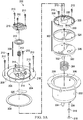
- FIG 2 is a perspective view of an instillation regulator 200 illustrating additional details that may be associated with some embodiments of the therapy system 100.
- the instillation regulator 200 may be an example embodiment of the instillation regulator 116 of Figure 1 .
- the instillation regulator 200 generally includes a housing, which may be formed by a body 202 and a head 204 coupled to the body 202, as shown in the example embodiment of Figure 2 .
- Some embodiments of the head 204 may include an extension 205.
- the body 202 may include a flange 206, and the head 204 may include a flange 208.
- the body 202 may be cylindrical in some embodiments, as illustrated in the example of Figure 2 , and the head 204 may be circular with a cylindrical extension 205, also as illustrated in the example of Figure 2 .
- the flange 206 and the flange 208 may be coupled with fasteners 210, or may be coupled with other mechanical, thermal, electrical, or chemical couplings.
- the dimensions of the flange 208 may be similar to the dimensions of the flange 206 to facilitate a secure coupling.
- the instillation regulator 200 may have fluid ports adapted for coupling to fluid conductor, such as a tube.
- the body 202 may have a negative-pressure port 212, and the head 204 may have a solution inlet port 214 and a solution outlet port 216.
- a retention cap 218 may also be coupled to the head 204 in some embodiments of the instillation regulator 200, and the body 202 may additionally comprise a vent 220, as shown in the example embodiment of Figure 2 .
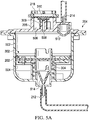
- Figure 3A and Figure 3B are assembly views illustrating additional details that may be associated with some embodiments of an instillation regulator, such as the instillation regulator 200 of Figure 2 .
- some embodiments of the instillation regulator 200 may include a piston, an elastic device, and a gasket.
- a piston can be a flexible or movable barrier, for example, illustrated in Figure 3A as a piston 302.
- An elastic device may be a spring or rubber, for example, illustrated in Figure 3A as a spring 304.
- the spring 304 may be disposed within a cavity 306 of the body 202, generally between the piston 302 and the body 202, as illustrated in the example embodiment of Figure 3A .
- the spring 304 may be a coil spring coaxial with the piston 302, as shown in the example of Figure 3A .
- the cavity 306 may be cylindrical, and the piston 302 may be rounded to fit within the cavity 306 of the body 202.
- the piston 302 may also reciprocate within the cavity 306.
- a gasket 308 may be disposed between the flange 206 and the flange 208.
- the instillation regulator 200 may also include an outlet check valve 309 disposed between the head 204 and the retention cap 218.
- the outlet check valve 309 may be a diaphragm valve having a diaphragm 310 and an elastic device such as a spring 312.
- the diaphragm 310 may be a flexible membrane or partition, such as a thin flexible disk.
- the spring 312 may be disposed within the extension 205 over a retention boss 314, which can restrict lateral movement of the spring 312.
- a flow limiter may comprise a hydrophobic filter 316 and a retaining ring 318, as illustrated in Figure 3A and Figure 3B .
- the hydrophobic filter 316 is generally configured to be disposed in or otherwise engage the vent 220, and the retaining ring 318 may be disposed around or otherwise coupled to the hydrophobic filter and the vent 220 to secure the hydrophobic filter 316 to the vent 220.
- a flow limiter may comprise an adjustable valve, such as a needle valve.
- the head 204 may include a passage configured to fluidly couple the extension 205 and the solution outlet port 216.
- the passage may be formed by a membrane 320 coupled to the head 204 to enclose a channel 322 formed in the head 204.
- the piston 302 may comprise a flexible seal disposed between a base and a retainer.
- the piston 302 of Figure 3A and Figure 3B includes a seal 324, a seal base 326, and a seal retainer 328.
- the seal 324 may be an elastomer or other flexible material, for example, while the seal base 326 and the seal retainer 328 preferably provide strength and rigidity to support the seal 324.
- the seal base 326 and the seal retainer 328 may include ribs 330 to provide further structural support.
- the seal base 326 may include one or more alignment pins 332, which can be configured to engage one or more alignment guides 334.
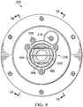
- Figure 4 is a top view illustrating additional details that may be associated with some embodiments of an instillation regulator, such as the instillation regulator 200.
- the retention cap 218 may be vented to expose the diaphragm 310 to the ambient environment.
- the retention cap 218 may comprise a support ring 402 and cross-bars 404 coupled to the support ring 402.
- the cross-bars 404 are generally configured to protect the diaphragm 310 and provide a fluid path between the diaphragm 310 and the ambient environment.
- a grid, a mesh, or other suitable porous structure may be coupled to the support ring to provide similar protection and fluid communication.
- the solution inlet port 214 and the solution outlet port 216 may be disposed on, in, or through the head 204, adjacent to the retention cap 218 and outside the support ring 402.
- Figure 5A is a sectional view of the instillation regulator 200 of Figure 4 taken on line 5A-5A, illustrating additional details that may be associated with some embodiments of the instillation regulator 200 in a first state.
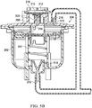
- Figure 5B is a sectional view of the instillation regulator 200 of Figure 4 taken on line 5B-5B, illustrating additional details that may be associated with some embodiments of the instillation regulator 200 in a second state.
- the head 204 can be coupled to the body 202 to enclose the piston 302 and fluidly isolate the cavity 306 from the ambient environment.
- the piston 302 may partition or separate the cavity 306 into a first chamber 502 and a second chamber 504.
- the piston 302 may engage the body 202 to provide a seal between the first chamber 502 and the second chamber 504.
- the seal 324 may press against a side wall of the body 202 to fluidly isolate the first chamber 502 from the second chamber 504.
- the diaphragm 310 may be coupled to the extension 205 to form a third chamber 506, generally defined by a portion of the head 204, the extension 205, and the diaphragm 310.
- the spring 312 may be disposed in the third chamber 506 between the diaphragm 310 and the head 204.
- the spring 312 may be disposed around the retention boss 314, as shown in the instillation regulator 200 of Figure 5A and Figure 5B .
- a peripheral edge of the diaphragm 310 may be supported by the extension 205, and an interior portion of the diaphragm 310 may engage the spring 312.
- the retention cap 218 may be coupled to the head 204 to secure the peripheral edge of the diaphragm 310 between the retention cap 218 and the extension 205.
- a passage 508 through the retention boss 314 can fluidly couple the first chamber 502 and the third chamber 506 through the outlet check valve 309.
- a passage 510 in the head 204 may also fluidly couple the third chamber 506 to the solution outlet port 216.
- the passage 508 and the passage 510 can provide a fluid path between the first chamber 502 and the solution outlet port 216 through the outlet check valve 309, which may be configured to be closed by negative pressure in the first chamber 502.
- Some embodiments of the regulator 200 may also include an inlet check valve 512 and an outlet check valve 514.
- the inlet check valve 512 may be fluidly coupled to the first chamber 502 and configured to be opened by negative pressure in the first chamber 502.
- the outlet check valve 514 may be fluidly coupled to the second chamber 504 and configured to be opened by negative pressure delivered to the negative-pressure port 212 or by an increase in pressure in the second chamber 504.
- the inlet check valve 512 may be disposed between the solution inlet port 214 and the first chamber 502, and the outlet check valve 514 may be disposed between the negative-pressure port 212 and the second chamber 504.
- the spring 304 may be disposed in the second chamber 504 against the piston 302 and the body 202 to bias the piston.
- the piston spring 516 may have a first end disposed around a retention boss 518 to restrict lateral movement, and may have a second end engaged to the piston 302.
- the spring 304 may bias the piston toward the head 204.
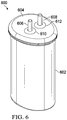
- FIG. 6 is a perspective view of an instillation regulator 600, illustrating details that may be associated with another example embodiment of the instillation regulator 116.
- the instillation regulator 600 generally includes a housing, which may be formed by a body 602 and a cap 604 coupled to the body 602, as shown in the example embodiment of Figure 6 .
- Some embodiments of the instillation regulator 600 may have fluid ports adapted for coupling to a tube or other fluid conductor.
- the instillation regulator 600 may have a first fluid port, such as the solution inlet port 606, which may extend through an inlet port opening 610 of the cap 604, and a second fluid port, such as the solution outlet port 608, which may extend through an outlet port opening 612.
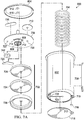
- Figure 7A and Figure 7B are assembly views illustrating additional details that may be associated with some embodiments of an instillation regulator, such as the instillation regulator 600 of Figure 6 .
- Some embodiments of the instillation regulator 600 may include a piston, an elastic device, and a gasket.
- the piston can be a flexible or movable barrier, for example, illustrated in Figure 7A as a piston 702.
- An elastic device may be a spring or rubber, for example, illustrated in Figure 7A as a spring 704.
- the spring 704 may be disposed within a cavity 706 of the body 602 of the instillation regulator 600, generally between the piston 702 and the body 602, as illustrated in the example embodiment of Figure 7B .
- the spring 704 may be a coil spring coaxial with the piston 702, as shown in the example of Figure 7A .
- the cavity 706 may be a cylindrical bore, and the piston 702 may be rounded to fit within the cavity 706 of the body 602. The piston 702 may also reciprocate within the cavity 706.
- the body 602 of the instillation regulator 600 may also comprise a window 738, which may allow viewing the interior of the instillation regulator 600 through an opening 740.
- a window 738 may allow viewing the interior of the instillation regulator 600 through an opening 740.
- the position of the piston 702 or the fluid in the cavity 706 may be viewed through the window 738 and the opening 740 in some embodiments.
- the instillation regulator 600 may also include a head 708, which may be disposed between the body 602 and the cap 604.
- the instillation regulator 600 may also include an outlet check valve 710 disposed between the head 708 and the cap 604.
- the outlet check valve 710 may be a diaphragm valve comprising a flexible membrane or partition, such as a thin flexible disk.
- a membrane 736 may also be disposed between the cap 604 and a channel 727 of the head 708.
- the head 708 may comprise an extension 705, and a valve seat 730 within the extension 705 configured to engage the outlet check valve 710.
- a flow limiter may comprise a hydrophobic filter 716, as illustrated in Figure 7A and Figure 7B .
- the hydrophobic filter 716 is generally configured to be disposed in or otherwise engage a vent 719, and a retaining ring 717 may be disposed around or otherwise coupled to the hydrophobic filter 716 and the vent 719 to couple the hydrophobic filter 716 to the vent 719.
- the retaining ring 717 may be coupled to or integral with a sealing membrane 718, as illustrated in the example embodiment of Figure 7A and Figure 7B .
- the head 708 may also include a passage configured to fluidly couple the valve seat 730 to the solution outlet port 608.
- an integrated fluid conductor may be formed by a membrane 720 coupled to the head 708 to enclose a channel 712 formed in the head 708.
- Another passage may fluidly couple the solution outlet port 608 to the channel 727.
- an integrated fluid conductor may be formed by coupling the membrane 720 to the head 708 to enclose a channel 714.
- the membrane 736 may also be coupled to the head 708 to enclose the channel 727.
- any or all of the channel 712, the channel 714 and the channel 727 may be integrally molded into the head 708.
- the body 602 may also include one or more passages configured to fluidly couple the channel 727 to the cavity 706.
- the body 602 may include a fluid conductor formed by the sealing membrane 718 coupled to the body 602 to enclose a channel 723, and a passage 722 in the body 602 may fluidly couple the channel 723 and the channel 727.
- either or both of the passage 722 and the channel 723 may be integrally molded in the body 602.
- the piston 702 may comprise a conformable seal disposed between a base and a retainer.
- the piston 702 of Figure 7A and Figure 7B includes a seal 724, a seal base 726, and a seal retainer 728.
- the seal 724 may be an elastomer or other flexible material, for example, while the seal base 726 and the seal retainer 728 may be a rigid plastic to provide strength and rigidity to support the seal 724.
- An inlet check valve 742 may also be disposed between the head 708 and the seal retainer 728, fluidly coupled to the solution inlet port 606.
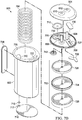
- Figure 8 is a top view illustrating additional details that may be associated with some embodiments of an instillation regulator, such as the instillation regulator 600.
- the instillation regulator 600 may have an ovate profile to accommodate the cavity 706 and the passage 722.
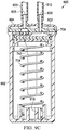
- Figure 9A is a sectional view of the instillation regulator 600 of Figure 8 taken on line 9A-9A, illustrating additional details that may be associated with some embodiments of the instillation regulator 600.
- Figure 9B is a sectional view of the instillation regulator 600 of Figure 8 taken on line 9B-9B, illustrating additional details that may be associated with some embodiments of the instillation regulator 600.
- Figure 9C is a sectional view of the instillation regulator 600 of Figure 8 taken on line 9C-9C, illustrating additional details that may be associated with some embodiments of the instillation regulator 600.
- the head 708 can be coupled to the body 602 to fluidly isolate the cavity 706 from the ambient environment, and the piston 702 may partition or separate the cavity 706 into a first chamber 902 and a second chamber 904. Moreover, the piston 702 may engage the body 602 to provide a seal between the first chamber 902 and the second chamber 904. For example, as shown in the example embodiment of Figure 9A , the seal 724 may press against a side wall of the body 602 to fluidly isolate the first chamber 902 from the second chamber 904.
- the outlet check valve 710 may be coupled to the extension 705 to form a third chamber 924, generally defined by a portion of the head 708, the extension 705, and the outlet check valve 710.
- a peripheral edge of the outlet check valve 710 may be supported or coupled to the extension 705.
- the cap 604 can be disposed on the head 708 to secure the outlet check valve 710 to the extension 705.
- a passage through the valve seat 730 may fluidly couple the first chamber 902 and the third chamber 924.
- the channel 712 may also fluidly couple the third chamber 924 to the solution outlet port 608.
- the inlet check valve 742 may be fluidly coupled to the first chamber 902 and configured to be opened by negative pressure in the first chamber 902. Some embodiments may also comprise an outlet check valve 710 fluidly coupled to the second chamber 904 and configured to be opened by negative pressure in the channel 723 or by an increased pressure in the second chamber 904.
- the inlet check valve 742 may be disposed between the solution inlet port 606 and the first chamber 902, and the outlet check valve 914 may be disposed between the solution outlet port 608 and the second chamber 904.
- the spring 704 may be disposed between the piston 702 and the body 602 in some embodiments.
- the spring 704 may have a first end disposed around a retention boss 918 to restrict lateral movement, and may have a second end engaged to the piston 702.
- the instillation regulator 600 may be primed during negative-pressure intervals, and may instill a solution during venting intervals.
- negative pressure can be supplied by a negative-pressure therapy unit (not shown) and delivered by a tube 912 to the instillation regulator 600.
- negative pressure may be delivered to the second chamber 904 through the solution outlet port 608, the passage 722, and the channel 723. Negative pressure in the second chamber 904 can move the piston 702, expanding the first chamber 902 and compressing the second chamber 904. If the first chamber 902 expands, pressure in the first chamber 902 can decrease proportionately.
- Negative pressure in the first chamber 902 can have the effect of actively drawing instillation solution into the first chamber 902 through the solution inlet port 606.
- the distance that the piston 702 travels can determine a dosage volume of instillation solution.
- the first chamber 902 may be lined with a suitable material to prevent contamination from mechanical components or lubricants.
- the first chamber 902 may be lined with a film bag, an elastomeric bag, or a compressible bellows.
- the instillation dosage may be adjusted. Such capability may be achieved by adjusting the distance traveled of the movable components during negative-pressure and venting intervals.
- the spring 704 may be compressed so that the distance traveled by the piston 702 can be limited. This may result from more quickly reaching the point where the negative pressure applied to the second chamber 904 for compressing the spring 704 can no longer overcome the force exerted by the spring 704.
- Other example embodiments may adjust the instillation dosage by reducing the height of the second chamber 904, for example, by screwing the first chamber 902 further into the second chamber 904 using a threaded mechanism.
- Yet another example may include controlling the dosage of instillation fluid delivered by limiting the travel of the piston 702 within the second chamber 904 by adjusting the height of a stop block located within the second chamber 904, under the piston 702. Additional examples may include restricting the flow of instillation fluid through either the solution inflow tube 920 or the solution outflow tube 912 using, for example, a valve, or by restricting the rate at which the piston 702 recovers.
- Expansion of the first chamber 902 may also have the effect of decreasing pressure in the third chamber 924, as pressure between the first chamber 902 and the third chamber 924 may be equalized through the passage 926.
- the decreased pressure in the third chamber 924 may have the effect of closing the outlet check valve 710, which can prevent instillation of solution to a dressing during a negative-pressure interval.
- the vent 719 may provide fluid communication between the second chamber 904 and the ambient environment, which can also have the effect of increasing pressure in the second chamber 904.
- Increased pressure in the second chamber 904 during a venting interval can have the effect of moving the piston 702, compressing the first chamber 902 and expanding the second chamber 904. If the first chamber 902 is compressed, pressure in the first chamber 902 can increase proportionately. The resulting increase in pressure can move solution out of the first chamber 902 through the valve seat 730, the channel 712, and the solution outlet port 608, instilling solution to a tissue site through the solution outflow tube 912.
- the inlet check valve 742 can prevent back-flow through the solution inlet port 606 during instillation, and the outlet check valve 914 can prevent solution from moving into the second chamber 904 from the channel 723 during instillation.
- a flow limiter such as the hydrophobic filter 716 can control the rate of venting between the second chamber 904 and the ambient environment through the vent 719, which can also determine the rate at which the piston 702 moves and the rate at which solution can be instilled from the first chamber 902.
- the surface area of the hydrophobic filter 716 can determine the vent rate and can be calibrated to provide a prescribed instillation rate.
- Figure 10 is a schematic diagram illustrating an example embodiment of a fluid management system 1000 comprising an instillation regulator 1002 disposed within an exudate container 1004.
- the instillation regulator 1002 is an example embodiment of the instillation regulator 116 of Figure 1
- the exudate container 1004 may be an example embodiment of the container 112 of Figure 1 .
- the fluid management system 1000 may also include an ancillary instillation solution source, such as a solution bag 1006.
- the solution bag 1006 may be an example embodiment of the solution source 114 of Figure 1 .
- the solution bag 1006 may be externally mounted on the exudate container 1004, as illustrated in Figure 10 .
- the solution bag 1006 may be secured to a pole or other hanger, preferably in close proximity to the exudate container 1004.
- the instillation regulator 1002 may be analogous in many respects to the instillation regulator 200 or the instillation regulator 600.
- the instillation regulator 1002 may include a housing 1008, a solution inlet port 1010, a solution outlet port 1012, and a negative-pressure port 1014.
- the instillation regulator 1002 may also include a piston 1016 disposed in a cavity of the housing 1008.
- the piston 1016 may partition or separate the cavity into a first chamber 1018 and a second chamber 1020.
- the piston 1016 may engage the housing 1008 to provide a seal between the first chamber 1018 and the second chamber 1020.
- a spring 1022 may be disposed between the piston 1016 and the housing 1008, as illustrated in the example embodiment of Figure 10 .
- the piston 1016 may reciprocate within the housing 1008, varying the volume of the first chamber 1018 and the second chamber 1020.
- the instillation regulator 1002 may be disposed within an interior space of the exudate container 1004 in some embodiments.
- the instillation regulator 1002 may be fastened to a wall of the exudate container 1004, or may be integrally molded with the exudate container 1004.
- the instillation regulator 1002 may also be fluidly coupled to the solution bag 1006, to a dressing (not shown in Figure 10 ), and to a negative-pressure source (not shown in Figure 10 ).
- the fluid management system 1000 may provide a fluid path 1026 between the solution bag 1006 and the solution inlet port 1010, a fluid path 1028 between the solution outlet port 1012 and a dressing, and a fluid path 1030 between the negative-pressure port 1014 and a negative-pressure source.
- the fluid path 1030 may additionally couple the negative-pressure source to the dressing through the exudate container 1004 in some embodiments.
- Each of the fluid path 1026, the fluid path 1028, and the fluid path 1030 may be comprised of more than one fluid conductor, coupled together through suitable interfaces.
- the fluid path 1026 may include an integrated fluid conductor molded into the exudate container 1004.
- the fluid path 1026 may include a tube.
- a fluid conductor can be coupled on a first end to the solution inlet port 1010 and terminate on a second end with an interface 1032 through the exudate container 1004.
- Another fluid conductor may be coupled between the interface 1032 and the solution bag 1006.
- the fluid path 1026 may be a tube, which can be coupled on a first end to the solution inlet port 1010, exit the exudate container 1004 through the interface 1032, and be coupled or configured to be coupled on a second end to the solution bag 1006.
- the fluid path 1028 may include an integral fluid conductor molded into the exudate container 1004.
- the fluid path 1028 may include a tube.
- a fluid conductor can be coupled on a first end to the solution outlet port 1012 and terminate on a second end with an interface 1034 through the exudate container 1004.
- Another tube or fluid conductor may be coupled between the interface 1034 and a dressing to complete a fluid path to the dressing.
- the fluid path 1028 may be a tube, which can be coupled on a first end to the solution outlet port 1012, exit the exudate container 1004 through the interface 1034, and be coupled or configured to be coupled on a second end to a dressing.
- the fluid path 1030 may similarly include an integrated fluid conductor or a tube coupled to a negative-pressure source through an interface 1036.
- Figure 11 is a schematic diagram illustrating another example embodiment of a fluid management system 1100 comprising the instillation regulator 1002 disposed within an exudate container 1104.
- the exudate container 1104 may be another example embodiment of the container 112 of Figure 1 .
- the instillation regulator 1002 may be fastened to a wall of the exudate container 1104, or may be integrally molded with the exudate container 1104.
- the fluid management system 1100 may also include an instillation solution source, such as a syringe 1106.
- the syringe 1106 may be an example embodiment of the solution source 114 of Figure 1 .
- the syringe 1106 may be externally mounted on the exudate container 1104, as illustrated in Figure 10 .
- the syringe 1106 may be secured to a pole or other hanger, preferably in close proximity to the exudate container 1104.
- the syringe 1106 can prime the fluid management system 1100 with instillation fluid that can be obtained from other sources, such as from larger containers or from multiple containers.
- the syringe 1106 may also be advantageous for accurately recording dosages of instillation solution administered through the fluid management system 1100.
- Figure 12 is a schematic diagram illustrating another alternative embodiment of a fluid management system 1200.
- the fluid management system 1200 may include the instillation regulator 1002 integrated with an exudate container 1204.
- the exudate container 1204 may be another example embodiment of the container 112 of Figure 1 .
- the instillation regulator 1002 may be fastened to a wall of the exudate container 1204, or may be integrally molded with the exudate container 1204.
- the fluid management system 1200 may also include an instillation solution source, such as a solution container 1206.
- the solution container 1206 may be another example embodiment of the solution source 114 of Figure 1 .
- the solution container 1206 may be integrated with the exudate container 1204 to provide a single disposable unit.
- the solution container 1206 may be a pouch comprising a suitable plastic or liquid-impermeable film welded or otherwise secured to an external surface of the exudate container 1204.
- the solution container 1206 may be a rigid plastic integrally molded with the exudate container 1204.
- the fluid path 1026 may also be integrated in the exudate container 1204 in some embodiments to reduce external tubes.
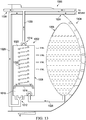
- Figure 13 is a schematic diagram illustrating another alternative embodiment of a fluid management system 1300.
- the fluid management system 1300 may include the instillation regulator 1002 disposed within an exudate container 1304.
- the exudate container 1304 may be an example embodiment of the container 112 of Figure 1 .
- the instillation regulator 1002 may be fastened to a wall of the exudate container 1304, or may be integrally molded with the exudate container 1304.
- the fluid management system 1300 may also include an instillation solution source, such as a solution container 1306.
- the solution container 1306 may be an example embodiment of the solution source 114 of Figure 1 .
- the solution container 1306 may be integrated with the exudate container 1304 to provide a single disposable unit.
- the solution container 1306 may be a flexible pouch disposed within an interior space of the exudate container 1304. Disposing the solution container 1306 within the exudate container 1304 may be advantageous for transport and storage, and may also prevent tampering and use of uncontrolled instillation solution. The volume displaced by the solution container 1306 can be reduced as instillation solution is delivered to a tissue site, thereby increasing the free volume in the exudate container 1304 available for collecting exudate and used instillation solution. A non-return valve can prevent the solution container 1306 from expanding under negative pressure in the exudate container 1304.
- FIG 14 is a schematic diagram illustrating yet another example embodiment of a fluid management system 1400.
- the fluid management system 1400 may include the instillation regulator 1002 coupled externally to an exudate container 1404.
- the instillation regulator 1002 may be disposed within, integrated with, or coupled to an adapter housing 1406, which can be coupled to the exudate container 1404.
- the exudate container 1404 and the adapter housing 1406 may each be configured with suitable interfaces to fluidly couple the solution inlet port 1010 to an instillation solution source (not shown in Figure 14 ), and to fluidly couple the solution outlet port 1012 to a dressing (not shown in Figure 14 ).
- the exudate container 1404 and the adapter housing 1406 may also include suitable interfaces for fluidly coupling a negative-pressure source (not shown in Figure 14 ) to the negative-pressure port 1014 and to a dressing.
- a negative-pressure source not shown in Figure 14
- the instillation regulator 1002 or the adapter housing 1406 may be detached from the exudate container 1404 and re-used, particularly for a single patient.
- Figure 15 is a schematic diagram illustrating additional details that may be associated with some embodiments of a fluid management system 1500.
- the fluid management system 1500 may be analogous to any of the previously described embodiments of a fluid management system, or any combination of features previously described.
- the fluid management system 1500 may include the instillation regulator 1002 disposed within an exudate container 1504.
- the exudate container 1504 may be an example embodiment of the container 112 of Figure 1 .
- the instillation regulator 1002 may be fastened to a wall of the exudate container 1504, or may be integrally molded with the exudate container 1504.
- the fluid management system 1500 may optionally include a means for controlling or adjusting a dosage of instillation solution.
- a pin or adjustable lever 1506 may limit the range of motion of the piston 1016 in some embodiments.
- the spring rate of the spring 1022 may be increased or decreased.
- FIG 16 is an assembly view illustrating an example embodiment of a fluid management system 1600.
- the fluid management system 1600 may include a container housing 1602, an instillation regulator 1604, a panel 1606, and a seal 1608.
- the container housing 1602 and the panel 1606 are preferably constructed from a material that is impermeable to fluid, such as a rigid or semi-rigid plastic.
- the seal 1608 preferably comprises a material that is relatively pliable and impermeable to fluid.
- the seal 1608 may be manufactured from a non-porous polyester film, preferably having a thickness between 0.1 millimeters and 0.2 millimeters.
- the seal 1608 also preferably comprises an adhesive or other suitable means for attaching the seal 1608 to the panel 1606.
- the seal 1608 may include an acrylic adhesive applied to one side, preferably having a thickness of about 0.15 millimeters.
- the seal 1608 may be an adhesive label or integrated with product labeling.
- the fluid management system 1600 may also include tubes or other fluid conductors for fluidly coupling the fluid management system 1600 to a tissue site or other components of a therapy system, such as the therapy system 100.
- the fluid management system 1600 may include a tube 1610 for coupling the container housing 1602 to a tissue site, a tube 1612 for coupling the container housing 1602 to an instillation solution source, and another tube 1614 for coupling the container housing 1602 to a tissue site.
- the container housing 1602 may include fluid ports adapted for coupling to tubes or other fluid conductors.
- the container housing 1602 may include a fluid port 1616 adapted for coupling to the tube 1610, a fluid port 1618 adapted for coupling to the tube 1612, and a fluid port 1620 adapted for coupling to the tube 1614.
- the instillation regulator 1604 may be similar or analogous to the instillation regulator 1002 in many respects.
- the instillation regulator 1604 may have fluid ports, such as a solution outlet port 1622 and a solution inlet port 1624, analogous to the solution outlet port 216 and the solution inlet port 214, respectively.
- the instillation regulator 1604 may also have retention clips 1626 adapted to mechanically couple the instillation regulator 1604 to the panel 1606.
- a tube or other fluid conductor may also be coupled to the solution outlet port 1622 and the solution inlet port 1624.
- a tube 1628 may be coupled to the solution outlet port 1622 and a tube 1630 may be coupled to the solution inlet port 1624.
- the panel 1606 may also include fluid ports adapted for coupling to a tube or other fluid conductor.
- the panel 1606 may include a port 1632, a port 1634, and a port 1636.
- a hydrophobic filter 1638 may also be coupled to or integral with some embodiments of the panel 1606.
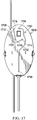
- Figure 17 is a rear view of the panel 1606 of Figure 16 , illustrating additional details that may be associated with some embodiments.
- fluid channels may be integrated into some embodiments of the panel 1606.
- the panel 1606 of Figure 17 may include a channel 1702, a channel 1704, and a channel 1706.
- each of the channel 1702, the channel 1704, and the channel 1706 may be an open channel, as shown in Figure 17 .
- Such an open channel may, for example, be formed as a groove, furrow, cut, depression, or gutter in the panel 1606.
- an open channel may have a rectangular, semi-circular, or trapezoidal cross-section, for example.
- a passage through the panel 1606 may also be disposed at each terminus of the channels 1702-1706 in some embodiments.
- a passage 1708 may be disposed at a first terminus of the channel 1702
- a passage 1710 may be disposed at a second terminus of the channel 1702.
- a passage 1712 may be disposed at a first terminus of the channel 1704 and a passage 1714 may be disposed at a second terminus of the channel 1704
- a passage 1716 and a passage 1718 may be disposed at opposing ends of the channel 1706.
- some or all of the passages 1708-1718 may be fluidly coupled to a fluid port on the opposing side of the panel 1606.
- the passage 1710 may be fluidly coupled to the port 1636
- the passage 1714 may be fluidly coupled to the port 1634
- the passage 1718 may be fluidly coupled to the port 1632.
- the panel 1606 may include additional passages, such as a passage 1720, which can fluidly couple a first side of the panel 1606 to a second side of the panel 1606.
- the passage 1720 can be fluidly coupled to the hydrophobic filter 1638.
- the seal 1608 may be attached to the panel 1606 and cover the channels 1702-1706 to form integrated fluid conductors.
- the seal 1608 may cover the channel 1702 to form an integrated fluid conductor between the passage 1708 and the passage 1710.
- the seal 1608 preferably covers and seals each of the channels 1702-1706, and each of the channels 1702-1706 is preferably deep enough to ensure that deformation of the seal under negative pressure does not cause the seal to block the channels 1702-1706.
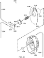
- Figure 18 is a perspective view of an example embodiment of the assembled fluid management system 1600. As illustrated in Figure 18 , the tube 1610 may be coupled to the port 1616, the tube 1612 may be coupled to the port 1618, and the tube 1614 may be coupled to the port 1620.
- Figure 19 is a section view of the fluid management system 1600 taken along line 19-19 of Figure 18 , illustrating additional details that may be associated with some embodiments.
- the panel 1606 is preferably configured to be fastened to the container housing 1602 to enclose the instillation regulator 1604 and form an exudate container, which may be suitable for use with some embodiments of the fluid management systems previously described.
- the fluid management system 1600 may be assembled to provide fluid paths analogous to the fluid path 1026, the fluid path 1028, and the fluid path 1030.
- a fluid path analogous to the fluid path 1026 may be provided by coupling a first end of the tube 1612 to the port 1618, and coupling a second end of the tube 1612 to an instillation solution source, such as the solution bag 1006, the syringe 1106, or the solution container 1206.
- the port 1618 may provide a fluid path from the tube 1612 to the passage 1712
- the channel 1704 can provide a fluid path from the passage 1712 to the passage 1714.
- the passage 1714 can provide a fluid path from the channel 1704 to the port 1634.
- the tube 1630 can provide a fluid path between the port 1634 and the solution inlet port 1624, thereby completing a fluid path between the instillation solution source and the solution inlet port 1624.
- a fluid path analogous to the fluid path 1028 may also be assembled by coupling a first end of the tube 1614 to the port 1620, and coupling a second end of the tube 1614 to a dressing, such as the dressing 102.
- the tube 1628 can provide a fluid path between the solution outlet port 1622 and the port 1632.
- the port 1632 can provide a fluid path between the tube 1628 and the passage 1718, which can be in fluid communication with the channel 1706.
- the channel 1706 can provide a fluid path between the passage 1718 and the passage 1716, which can be in fluid communication with the port 1620, thereby completing a fluid path between the solution outlet port 1622 and the tube 1614.
- a fluid path analogous to the fluid path 1030 may be provided by fluidly coupling the passage 1720 to a negative-pressure source, such as the negative-pressure source 104, for example.
- the passage 1720 can provide a fluid path between a negative-pressure source and the interior of the container housing 1602, preferably through the hydrophobic filter 1638.
- the tube 1610 may be coupled to the port 1616, which can also be in fluid communication with the interior of the container housing 1602, thereby completing a fluid path between a negative-pressure source and the tube 1610.
- the tube 1610 can be fluidly coupled to a dressing or tissue site to extend the fluid path to the dressing or tissue site.
- the tube 1610 preferably has at least two lumens, and the port 1616 may also have two lumens in some embodiments.
- a first lumen of the tube 1610 may be fluidly coupled to a first lumen of the port 1616 to deliver negative-pressure to a dressing or tissue site
- a second lumen of the tube 1610 may be fluidly coupled to a second lumen of the port 1616 to provide a feedback path for negative-pressure from a dressing or tissue site.
- the first lumen of the port 1616 may be in fluid communication with the interior of the container housing 1602, and the second lumen of the port 1616 may be fluidly coupled to passage 1708 when assembled.
- the passage 1708 may provide a fluid path between the second lumen of the port 1616 and the channel 1702.
- the channel 1702 can provide a fluid path between the passage 1708 and the passage 1710, which can be in fluid communication with the port 1636.
- a tube or other fluid conductor, such as a tube 1902, may provide a fluid path between the port 1636 and a negative-pressure port 1904 of the instillation regulator 1604, thereby completing a fluid path between the second lumen of the tube 1610 and the negative-pressure port 1904.
- Figure 20 is an assembly view illustrating another example embodiment of a fluid management system.
- the fluid management system 2000 of Figure 20 may include a container housing 2002 and a panel 2004.
- the container housing 2002 and the panel 2004 are preferably constructed from a material that is impermeable to fluid, such as a rigid or semi-rigid plastic.
- the fluid management system 2000 also preferably includes an instillation regulator.
- a regulator body 2006 may be integrally molded with the panel 2004.
- the regulator body 2006 may be inserted through an aperture in the panel 2004.
- the regulator body 2006 has a cylindrical wall 2008 and a base 2010, and preferably has a major axis that is orthogonal to the plane of the panel 2004 to simplify molding.
- regulator components such as a spring 2012, a piston 2014, a first check valve 2016, a second check valve 2018, and a head 2020
- the piston 2014 may be disposed in the regulator body 2006 and partition the regulator body 2006 into two chambers, analogous to the first chamber 1018 and the second chamber 1020.
- the spring 2012 may be disposed between the piston 2014 and the base 2010, and the piston 2014 may reciprocate within the regulator body 2006.
- the head 2020 may be fastened to the regulator body 2006 to enclose the spring 2012 and the piston 2014.
- the head 2020 may also include a passage 2022 and a passage 2024.
- the base 2010 of the regulator body 2006 may include an aperture 2026, analogous to the negative-pressure port 1014.
- a hydrophobic filter 2028 is preferably disposed over the aperture 2026.
- the fluid management system 2000 may also include tubes or other fluid conductors for fluidly coupling the fluid management system 2000 to a tissue site or other components of a therapy system, such as the therapy system 100.
- the fluid management system 2000 may include a tube 2030 for coupling the fluid management system 2000 to a tissue site, a tube 2032 for coupling the fluid management system 2000 to an instillation solution source, and another tube 2034 for coupling the fluid management system 2000 to a dressing or tissue site.
- Figure 21 is another assembly view illustrating additional details that may be associated with some embodiments of the fluid management system 2000.
- the head 2020 may include a solution inlet port 2102 and a solution outlet port 2104, analogous to the solution inlet port 1010 and the solution outlet port 1012, respectively.
- the solution inlet port 2102 may be fluidly coupled to the passage 2022, and the solution outlet port 2104 may be fluidly coupled to the passage 2024.
- the panel 2004 may also include additional passages, such as a passage 2106 and a passage 2108, as shown in the example embodiment of Figure 21 .
- the panel 2004 is preferably configured to be fastened to the container housing 2002 to form an exudate container, which may be suitable for use with some embodiments of the fluid management systems previously described.
- the fluid management system 2000 may be assembled to provide fluid paths analogous to the fluid path 1026, the fluid path 1028, and the fluid path 1030.
- a fluid path analogous to the fluid path 1026 may be provided by coupling a first end of the tube 2032 to the solution inlet port 2102, and coupling a second end of the tube 2032 to an instillation solution source, such as the solution bag 1006, the syringe 1106, or the solution container 1206.
- the port 2102 may provide a fluid path from the tube 2032 to the passage 2022, which can be fluidly coupled to a chamber formed by the piston 2014 and the head 2020.
- a fluid path analogous to the fluid path 1028 may also be assembled by coupling a first end of the tube 2034 to the solution outlet port 2104, and coupling a second end of the tube 2034 to a dressing, such as the dressing 102.
- the passage 2024 can provide a path between the solution outlet port 2104 and the chamber formed by the piston 2014 and the head 2020.
- a fluid path analogous to the fluid path 1030 may be provided by fluidly coupling the passage 2106 to a negative-pressure source, such as the negative-pressure source 104, for example.
- the passage 2106 may be in fluid communication with the interior of the container housing 2002, preferably through a hydrophobic filter.
- the aperture 2026 can also be in fluid communication with the interior of the container housing 2002.
- the hydrophobic filter 2028 preferably provides a fluid path for negative-pressure between the aperture 2026 and the interior of the container housing 2002, but substantially blocks the fluid path for exudate and other liquids.
- instillation solution can be applied reliably while reducing the size, complexity, and number of parts needed for effective negative-pressure therapy with instillation.
- instillation therapy can be provided even if there is a fluid head height to overcome.
- Some embodiments can also eliminate or reduce the need for ancillary components, such as ancillary bags for instillation solution, providing a single disposable apparatus.
- Some embodiments can also use a single interface pad and tubeset.
Description
- The invention set forth in the appended claims relates generally to tissue treatment systems and more particularly, but without limitation, to apparatuses for providing negative-pressure therapy with instillation of topical treatment solutions.
- Clinical studies and practice have shown that reducing pressure in proximity to a tissue site can augment and accelerate growth of new tissue at the tissue site. The applications of this phenomenon are numerous, but it has proven particularly advantageous for treating wounds. Regardless of the etiology of a wound, whether trauma, surgery, or another cause, proper care of a wound is important to the outcome. Treatment of wounds or other tissue with reduced pressure may be commonly referred to as "negative-pressure therapy," but is also known by other names, including "negative-pressure wound therapy," "reduced-pressure therapy," "vacuum therapy," "vacuum-assisted closure," and "topical negative-pressure," for example. Negative-pressure therapy may provide a number of benefits, including migration of epithelial and subcutaneous tissues, improved blood flow, and micro-deformation of tissue at a wound site. Together, these benefits can increase development of granulation tissue and reduce healing times.
- There is also widespread acceptance that cleansing a tissue site can be highly beneficial for new tissue growth. For example, a wound can be washed out with a stream of liquid solution, or a cavity can be washed out using a liquid solution for therapeutic purposes. These practices are commonly referred to as "irrigation" and "lavage" respectively. "Instillation" is another practice that generally refers to a process of slowly introducing fluid to a tissue site and leaving the fluid for a prescribed period of time before removing the fluid. For example, instillation of topical treatment solutions over a wound bed can be combined with negative-pressure therapy to further promote wound healing by loosening soluble contaminants in a wound bed and removing infectious material. As a result, soluble bacterial burden can be decreased, contaminants removed, and the wound cleansed.
- While the clinical benefits of negative-pressure therapy and instillation are widely known, the cost and complexity of negative-pressure therapy can be a limiting factor in its application, and the development and operation of negative-pressure systems, components, and processes continues to present significant challenges to manufacturers, healthcare providers, and patients.
-
US2008/140029A1 discusses an apparatus for the treatment of a wound on a patient. The apparatus is arranged to administer localized negative pressure therapy to the wound using a hospital wall vacuum source and a drain line for removing exudate from the wound. The apparatus may also be capable of administering localized hyperbaric oxygen therapy to the wound using a hospital wall oxygen source and a supply line for supplying oxygen to the wound. The apparatus includes at least one regulator to control the application of negative pressure therapy and hyperbaric oxygen therapy. -
US5176642A discusses a medical apparatus for injecting or withdrawing biological or therapeutic fluid includes a syringe body defining a syringe cavity into which fluids can be introduced or withdrawn by way of a fluid port and a vacuum port. A piston is positioned for reversible movement in the syringe cavity between the fluid port and the vacuum port so that movement of the piston in response to a decrease in fluid pressure causes a resilient element positioned within the cavity to be compressed. The compressed spring provides a store of mechanical energy that can be used to drive the piston toward the fluid port and expel fluid contained in the first cavity through the fluid port when pressure within the syringe cavity is equalized. Control of vacuum and air inlet into the syringe cavity is controlled by a dual port valve connected to the syringe body. - The present invention provides an apparatus for managing fluid in a system for negative-pressure therapy as set forth in the appended claims. Illustrative embodiments are also provided to enable a person skilled in the art to make and use the claimed subject matter.
- The apparatus comprises an exudate container, a solution source, and an instillation regulator that can be pneumatically-actuated. The instillation regulator is coupled to the exudate container and to the solution source, and negative pressure from a negative-pressure source can actuate the instillation regulator. A negative-pressure source may be configured for a negative-pressure interval and a venting interval, and the instillation regulator is configured to draw instillation solution from the solution source during a negative-pressure interval and to instill the solution to a dressing during a venting interval.
- The instillation regulator has solution inlet port, a solution outlet port, and a negative-pressure port. The solution inlet port is fluidly coupled to a solution source, and the solution outlet port may be fluidly coupled to a dressing. The negative-pressure port may be fluidly coupled to a negative-pressure source, which can provide negative pressure through the negative-pressure port to actuate the instillation regulator.
- According to the invention, the instillation regulator includes a piston disposed within a housing. The piston partitions the housing into a first chamber and a second chamber. The solution inlet port is fluidly coupled to the solution source and to the first chamber. The solution outlet port is fluidly coupled to the first chamber and may be coupled to a dressing. The negative-pressure port may fluidly couple a negative-pressure source to the second chamber, so that negative pressure applied to the second chamber through the negative-pressure port during a negative-pressure interval can actuate the piston. For example, if negative pressure is applied to the second chamber, the pressure differential across the piston can move the piston within the housing, increasing the volume of the first chamber and decreasing the volume of the second chamber. An increase in the volume of the first chamber can decrease the pressure in the first chamber, drawing instillation solution from the solution source through the solution inlet port and into the first chamber. If the pressure in the second chamber is increased, such as during a venting interval, the pressure differential across the piston can reverse the movement of the piston to decrease the volume of the first chamber and increase the volume of the second chamber. Decreasing the volume of the first chamber can increase the pressure in the first chamber, expelling instillation solution from the first chamber through the solution outlet port. Check valves can be coupled to the solution inlet port and the solution outlet port to prevent drawing fluid through the solution outlet port and expelling fluid through the solution inlet port.
- In some embodiments, the instillation regulator may be disposed within an exudate container. For example, the instillation regulator may be integrally molded with an exudate container or may be mounted to an interior surface of an exudate container. In yet other example embodiments, the instillation regulator may be configured for coupling between an exudate container and a negative-pressure source.
- In some embodiments, instillation solution may be managed as an ancillary to an exudate container, but in other embodiments the instillation solution may be managed integrally to the exudate canister. For example, in some embodiments, a solution source may be externally mounted on an exudate container, but in other example embodiments, a solution source may be disposed within an exudate container.
- An apparatus having some or all of these illustrative features may also be used in a system for providing negative-pressure therapy with instillation of topical treatment solutions. For example, a system for treating a tissue site with negative-pressure and instillation therapy may include a dressing, an exudate container, and a negative-pressure source fluidly coupled to the dressing and the exudate container. The system may also include a source of instillation solution. An instillation regulator may be fluidly coupled to the solution source and to the negative-pressure source. Negative pressure from the negative-pressure source can actuate the instillation regulator to draw solution from the solution source. Venting the negative pressure can actuate the instillation regulator to instill the solution to the dressing.
- In yet other embodiments that are not part of the claimed invention, a method for treating a tissue site with negative pressure and topical instillation solution is also described. For example, a dressing may be applied to the tissue site and coupled to a negative-pressure source. An instillation regulator may also be fluidly coupled to the negative-pressure source and to the dressing. A source of instillation solution may be coupled to the instillation regulator. Solution may be drawn to the instillation regulator from the solution source during a negative-pressure interval, and solution may be instilled from the instillation regulator to the dressing during a venting interval.
- Objectives, advantages, and a preferred mode of making and using the claimed subject matter may be understood best by reference to the accompanying drawings in conjunction with the following detailed description of illustrative embodiments.
-
-
Figure 1 is a functional block diagram of an example embodiment of a therapy system that can provide negative-pressure therapy and instillation in accordance with this specification; -
Figure 2 is a perspective view illustrating additional details that may be associated with some example embodiments of an instillation regulator in the therapy system ofFigure 1 ; -
Figures 3A-3B are assembly views illustrating additional details that may be associated with some embodiments of the instillation regulator ofFigure 2 ; -
Figure 4 is a top view illustrating additional details that may be associated with some embodiments of the instillation regulator ofFigure 2 ; -
Figure 5A is a cross-section of the instillation regulator shown inFigure 4 taken alongline 5A-5A; -
Figure 5B is a cross-section of the instillation regulator shown inFigure 4 taken alongline 5B-5B; -
Figure 6 is a perspective view illustrating additional details of another example embodiment of an instillation regulator that may be associated with the therapy system ofFigure 1 ; -
Figures 7A-7B are assembly views illustrating additional details that may be associated with some embodiments of the instillation regulator ofFigure 6 ; -
Figure 8 is a top view illustrating additional details that may be associated with some embodiments of the instillation regulator ofFigure 6 ; -
Figure 9A is a cross-section of the instillation regulator shown inFigure 8 taken alongline 9A-9A; -
Figure 9B is a cross-section of the instillation regulator shown inFigure 8 taken alongline 9B-9B; -
Figure 9C is a cross-section of the instillation regulator shown inFigure 8 taken alongline 9C-9C; -
Figure 10 is a schematic diagram illustrating an example embodiment of a fluid management system comprising an instillation regulator disposed within an exudate container; -
Figure 11 is a schematic diagram illustrating another example embodiment of a fluid management system comprising the instillation regulator ofFigure 10 disposed within an exudate container; -
Figure 12 is a schematic diagram illustrating another alternative embodiment of a fluid management system; -
Figure 13 is a schematic diagram illustrating another alternative embodiment of a fluid management system; -
Figure 14 is a schematic diagram illustrating yet another example embodiment of a fluid management system; and -
Figure 15 is a schematic diagram illustrating additional details that may be associated with some embodiments of a fluid management system. - The following description of example embodiments provides information that enables a person skilled in the art to make and use the subject matter set forth in the appended claims, but may omit certain details already well-known in the art. The following detailed description is, therefore, to be taken as illustrative and not limiting.
- The example embodiments may also be described herein with reference to spatial relationships between various elements or to the spatial orientation of various elements depicted in the attached drawings. In general, such relationships or orientation assume a frame of reference consistent with or relative to a patient in a position to receive treatment. However, as should be recognized by those skilled in the art, this frame of reference is merely a descriptive expedient rather than a strict prescription.
-
Figure 1 is a simplified block diagram of an example embodiment of atherapy system 100 that can provide negative-pressure therapy with instillation of topical treatment solutions in accordance with this specification. Thetherapy system 100 may include a dressing and a negative-pressure source. For example, a dressing 102 may be fluidly coupled to a negative-pressure source 104, as illustrated inFigure 1 . A regulator, such as apressure regulator 106, may also be fluidly coupled to the dressing 102 and the negative-pressure source 104. A dressing may include a cover and a tissue interface. The dressing 102, for example, may include acover 108 and atissue interface 110. Thetherapy system 100 may also include an exudate container, such as acontainer 112, coupled to the dressing 102 and to the negative-pressure source 104. - The
therapy system 100 may also include a source of instillation solution. For example, asolution source 114 may be fluidly coupled to the dressing 102, as illustrated in the example embodiment ofFigure 1 . A second regulator, such as aninstillation regulator 116, may be fluidly coupled to thesolution source 114 and thedressing 102. In some embodiments, theinstillation regulator 116 may also be pneumatically coupled to the negative-pressure source 104, as illustrated in the example ofFigure 1 . Theinstillation regulator 116 may also be integrated with thecontainer 112 in some embodiments to provide a single, disposable product. - In general, components of the
therapy system 100 may be coupled directly or indirectly. For example, the negative-pressure source 104 may be directly coupled to thepressure regulator 106 and indirectly coupled to the dressing 102 through thepressure regulator 106. In some embodiments, components may be coupled by virtue of physical proximity, being integral to a single structure, or being formed from the same piece of material. Coupling may also include mechanical, thermal, electrical, or chemical coupling (such as a chemical bond) in some contexts. - Components may be fluidly coupled to each other to provide a path for transferring fluids (i.e., liquid and/or gas) between the components. In some embodiments, for example, components may be fluidly coupled through a tube. A "tube," as used herein, broadly refers to a tube, pipe, hose, conduit, or other fluid conductor with one or more lumina adapted to convey fluid between two ends. Typically, a tube is an elongated, cylindrical structure with some flexibility, but the geometry and rigidity may vary. A fluid conductor may also be integrally molded into a component in some embodiments.
- In operation, the
tissue interface 110 may be placed within, over, on, or otherwise proximate to a tissue site. Thecover 108 may be placed over thetissue interface 110 and sealed to tissue near the tissue site. For example, thecover 108 may be sealed to undamaged epidermis peripheral to a tissue site. Thus, the dressing 102 can provide a sealed therapeutic environment proximate to a tissue site, substantially isolated from the external environment, and the negative-pressure source 104 can reduce the pressure in the sealed therapeutic environment. Negative pressure applied across a tissue site through thetissue interface 110 in the sealed therapeutic environment can induce macro-strain and micro-strain in the tissue site, as well as remove exudate and other fluid from the tissue site, which can be collected in thecontainer 112 and disposed of properly. - The fluid mechanics of using a negative-pressure source to reduce pressure in another component or location, such as within a sealed therapeutic environment, can be mathematically complex. However, the basic principles of fluid mechanics applicable to negative-pressure therapy and instillation are generally well-known to those skilled in the art.
- In general, fluid flows toward lower pressure along a fluid path. Thus, the term "downstream" typically implies something in a fluid path relatively closer to a source of negative pressure or further away from a source of positive pressure; conversely, the term "upstream" implies something relatively further away from a source of negative pressure or closer to a source of positive pressure. Similarly, it may be convenient to describe certain features in terms of fluid "inlet" or "outlet" in such a frame of reference, and the process of reducing pressure may be described illustratively herein as "delivering," "distributing," or "generating" reduced pressure, for example. This orientation is generally presumed for purposes of describing various features and components herein.
- The term "tissue site" in this context broadly refers to a wound or defect located on or within tissue, including but not limited to, bone tissue, adipose tissue, muscle tissue, neural tissue, dermal tissue, vascular tissue, connective tissue, cartilage, tendons, or ligaments. A wound may include chronic, acute, traumatic, subacute, and dehisced wounds, partial-thickness burns, ulcers (such as diabetic, pressure, or venous insufficiency ulcers), flaps, and grafts, for example. The term "tissue site" may also refer to areas of any tissue that are not necessarily wounded or defective, but are instead areas in which it may be desirable to add or promote the growth of additional tissue. For example, negative pressure may be used in certain tissue areas to grow additional tissue that may be harvested and transplanted to another tissue location.
- "Negative pressure" generally refers to a pressure less than a local ambient pressure, such as the ambient pressure in a local environment external to a sealed therapeutic environment provided by the dressing 102. In many cases, the local ambient pressure may also be the atmospheric pressure at which a tissue site is located. Alternatively, negative pressure may be a pressure less than a hydrostatic pressure associated with tissue at the tissue site. Unless otherwise indicated, values of pressure stated herein are gauge pressures. Similarly, references to increases in negative pressure typically refer to a decrease in absolute pressure, while decreases in negative pressure typically refer to an increase in absolute pressure.
- A negative-pressure source, such as the negative-
pressure source 104, may be a reservoir of air at a negative pressure, or may be a manual or electrically-powered device that can reduce the pressure in a sealed volume, such as a vacuum pump, a suction pump, a wall suction port available at many healthcare facilities, or a micro-pump, for example. A negative-pressure source may be housed within or used in conjunction with other components, such as sensors, processing units, alarm indicators, memory, databases, software, display devices, or user interfaces that further facilitate negative-pressure therapy. While the amount and nature of negative pressure applied to a tissue site may vary according to therapeutic requirements, the pressure is generally a low vacuum, also commonly referred to as a rough vacuum, between -5 mm Hg (-667 Pa) and -500 mm Hg (-66.7 kPa). Common therapeutic ranges are between -75 mm Hg (-9.9 kPa) and -300 mm Hg (-39.9 kPa). In some embodiments, negative pressure may be applied intermittently or periodically, with intervals of negative-pressure and intervals of venting or positive-pressure. - The
tissue interface 110 can be generally adapted to contact a tissue site. Thetissue interface 110 may be partially or fully in contact with a tissue site. If a tissue site is a wound, for example, thetissue interface 110 may partially or completely fill the wound, or may be placed over the wound. Thetissue interface 110 may take many forms, and may have many sizes, shapes, or thicknesses depending on a variety of factors, such as the type of treatment being implemented or the nature and size of a tissue site. For example, the size and shape of thetissue interface 110 may be adapted to the contours of deep and irregular shaped tissue sites. In some embodiments, the tissue interface may be provided in a spiral cut sheet. Moreover, any or all of the surfaces of thetissue interface 110 may have an uneven, coarse, or jagged profile that can induce micro-strains and stresses at a tissue site. - In some embodiments, the
tissue interface 110 may be a manifold. A "manifold" in this context generally includes any substance or structure providing a plurality of pathways adapted to collect or distribute fluid across a tissue site. For example, a manifold may be adapted to receive negative pressure from a source and distribute negative pressure through multiple apertures across a tissue site, which may have the effect of collecting fluid from across a tissue site and drawing the fluid toward the source. In some embodiments, the fluid path may be reversed or a secondary fluid path may be provided to facilitate distributing fluid across a tissue site. - In some illustrative embodiments, the pathways of a manifold may be interconnected to improve distribution or collection of fluids across a tissue site. For example, cellular foam, open-cell foam, reticulated foam, porous tissue collections, and other porous material such as gauze or felted mat generally include pores, edges, and/or walls adapted to form interconnected fluid pathways. Liquids, gels, and other foams may also include or be cured to include apertures and fluid pathways. In some illustrative embodiments, a manifold may be a porous foam material having interconnected cells or pores adapted to distribute negative pressure across a tissue site. The foam material may be either hydrophobic or hydrophilic. The pore size of a foam material may vary according to needs of a prescribed therapy. For example, in some embodiments, the
tissue interface 110 may be a foam having pore sizes in a range of 400-600 microns. The tensile strength of thetissue interface 110 may also vary according to needs of a prescribed therapy. For example, the tensile strength of a foam may be increased for instillation of topical treatment solutions. In one non-limiting example, thetissue interface 110 may be an open-cell, reticulated polyurethane foam such as GranuFoam® dressing available from Kinetic Concepts, Inc. of San Antonio, Texas; in other embodiments thetissue interface 110 may be an open-cell, reticulated polyurethane foam such as a VeraFlo® foam, also available from Kinetic Concepts, Inc., of San Antonio, Texas. - In an example in which the
tissue interface 110 may be made from a hydrophilic material, thetissue interface 110 may also wick fluid away from a tissue site, while continuing to distribute negative pressure to the tissue site. The wicking properties of thetissue interface 110 may draw fluid away from a tissue site by capillary flow or other wicking mechanisms. An example of a hydrophilic foam is a polyvinyl alcohol, open-cell foam such as V.A.C. WhiteFoam® dressing available from Kinetic Concepts, Inc. of San Antonio, Texas. Other hydrophilic foams may include those made from polyether. Other foams that may exhibit hydrophilic characteristics include hydrophobic foams that have been treated or coated to provide hydrophilicity. - In some embodiments, the
tissue interface 110 may be constructed from bioresorbable materials. Suitable bioresorbable materials may include, without limitation, a polymeric blend of polylactic acid (PLA) and polyglycolic acid (PGA). The polymeric blend may also include without limitation polycarbonates, polyfumarates, and capralactones. Thetissue interface 110 may further serve as a scaffold for new cell-growth, or a scaffold material may be used in conjunction with thetissue interface 110 to promote cell-growth. A scaffold is generally a substance or structure used to enhance or promote the growth of cells or formation of tissue, such as a three-dimensional porous structure that provides a template for cell growth. Illustrative examples of scaffold materials include calcium phosphate, collagen, PLA/PGA, coral hydroxy apatites, carbonates, or processed allograft materials. - In some embodiments, the
cover 108 may provide a bacterial barrier and protection from physical trauma. Thecover 108 may also be constructed from a material that can reduce evaporative losses and provide a fluid seal between two components or two environments, such as between a therapeutic environment and a local external environment. Thecover 108 may be, for example, an elastomeric film or membrane that can provide a seal adequate to maintain a negative pressure at a tissue site for a given negative-pressure source. In some example embodiments, thecover 108 may be a polymer drape, such as a polyurethane film, that is permeable to water vapor but impermeable to liquid. Such drapes typically have a thickness in the range of 25-50 microns. For permeable materials, the permeability generally should be low enough that a desired negative pressure may be maintained. - An attachment device may be used to attach the
cover 108 to an attachment surface, such as undamaged epidermis, a gasket, or another cover. The attachment device may take many forms. For example, an attachment device may be a medically-acceptable, pressure-sensitive adhesive that extends about a periphery, a portion, or an entirety of thecover 108. In some embodiments, for example, some or all of thecover 108 may be coated with an acrylic adhesive having a coating weight between 25-65 grams per square meter (g.s.m.). Thicker adhesives, or combinations of adhesives, may be applied in some embodiments to improve the seal and reduce leaks. Other example embodiments of an attachment device may include a double-sided tape, paste, hydrocolloid, hydrogel, silicone gel, or organogel. - In some embodiments, the dressing 102 may also include a fluid interface configured to fluidly couple the negative-
pressure source 104 to the sealed therapeutic environment formed by thecover 108. In some embodiments, the fluid interface may include a flange portion that couples to thecover 108 and a portion that fluidly couples to a tube 120. In one exemplary embodiment, the fluid interface may be a T.R.A.C.® Pad or Sensa T.R.A.C.® Pad available from Kinetic Concepts, Inc. of San Antonio, Texas. In other exemplary embodiments, a tube may be inserted through thecover 108. Such a fluid interface can allow negative pressure to be delivered to the sealed therapeutic environment. For example, a fluid interface can provide a fluid conductor through thecover 108 to thetissue interface 110. In some embodiments, a fluid interface can also provide more than one fluid path through thecover 108 or merge more than fluid conductor into a single fluid path. For example, in some embodiments, a fluid interface can be fluidly coupled to both the negative-pressure source 104 and to theinstillation regulator 116. In one embodiment, such a fluid interface may provide a separate fluid path through thecover 108 for each of the negative-pressure source 104 and theinstillation regulator 116. In other embodiments, the fluid interface may merge separate fluid paths from the negative-pressure source 104 and theinstillation regulator 116 into a single fluid path through thecover 108. - The
container 112 is representative of a container, canister, pouch, or other storage component, which can be used to manage exudate and other fluid withdrawn from a tissue site. In many environments, a rigid container may be preferred or required for collecting, storing, and disposing of fluid. In other environments, fluid may be properly disposed of without rigid container storage, and a re-usable container could reduce waste and costs associated with negative-pressure therapy. - The
solution source 114 may also be representative of a container, canister, pouch, bag, or other storage component, which can provide a solution for instillation therapy. Compositions of solutions may vary according to a prescribed therapy, but examples of solutions that may be suitable for some prescriptions include hypochlorite-based solutions, silver nitrate (0.5%), sulfur-based solutions, biguanides, cationic solutions, and isotonic solutions. -
Figure 2 is a perspective view of aninstillation regulator 200 illustrating additional details that may be associated with some embodiments of thetherapy system 100. Theinstillation regulator 200 may be an example embodiment of theinstillation regulator 116 ofFigure 1 . Theinstillation regulator 200 generally includes a housing, which may be formed by abody 202 and ahead 204 coupled to thebody 202, as shown in the example embodiment ofFigure 2 . Some embodiments of thehead 204 may include anextension 205. In some embodiments, thebody 202 may include aflange 206, and thehead 204 may include aflange 208. Thebody 202 may be cylindrical in some embodiments, as illustrated in the example ofFigure 2 , and thehead 204 may be circular with acylindrical extension 205, also as illustrated in the example ofFigure 2 . Theflange 206 and theflange 208 may be coupled withfasteners 210, or may be coupled with other mechanical, thermal, electrical, or chemical couplings. The dimensions of theflange 208 may be similar to the dimensions of theflange 206 to facilitate a secure coupling. - Some embodiments of the
instillation regulator 200 may have fluid ports adapted for coupling to fluid conductor, such as a tube. For example, as shown inFigure 2 , thebody 202 may have a negative-pressure port 212, and thehead 204 may have asolution inlet port 214 and asolution outlet port 216. Aretention cap 218 may also be coupled to thehead 204 in some embodiments of theinstillation regulator 200, and thebody 202 may additionally comprise avent 220, as shown in the example embodiment ofFigure 2 . -
Figure 3A andFigure 3B are assembly views illustrating additional details that may be associated with some embodiments of an instillation regulator, such as theinstillation regulator 200 ofFigure 2 . For example, some embodiments of theinstillation regulator 200 may include a piston, an elastic device, and a gasket. A piston can be a flexible or movable barrier, for example, illustrated inFigure 3A as apiston 302. An elastic device may be a spring or rubber, for example, illustrated inFigure 3A as aspring 304. Thespring 304 may be disposed within acavity 306 of thebody 202, generally between thepiston 302 and thebody 202, as illustrated in the example embodiment ofFigure 3A . In some embodiments, thespring 304 may be a coil spring coaxial with thepiston 302, as shown in the example ofFigure 3A . Also as shown in the example embodiment ofFigure 3A andFigure 3B , thecavity 306 may be cylindrical, and thepiston 302 may be rounded to fit within thecavity 306 of thebody 202. Thepiston 302 may also reciprocate within thecavity 306. Agasket 308 may be disposed between theflange 206 and theflange 208. - The
instillation regulator 200 may also include anoutlet check valve 309 disposed between thehead 204 and theretention cap 218. For example, as shown in the illustrative embodiment ofFigure 3A , some embodiments of theoutlet check valve 309 may be a diaphragm valve having adiaphragm 310 and an elastic device such as aspring 312. Thediaphragm 310 may be a flexible membrane or partition, such as a thin flexible disk. Thespring 312 may be disposed within theextension 205 over aretention boss 314, which can restrict lateral movement of thespring 312. - Some embodiments of the
instillation regulator 200 may further include a flow limiter. For example, a flow limiter may comprise ahydrophobic filter 316 and a retainingring 318, as illustrated inFigure 3A andFigure 3B . Thehydrophobic filter 316 is generally configured to be disposed in or otherwise engage thevent 220, and the retainingring 318 may be disposed around or otherwise coupled to the hydrophobic filter and thevent 220 to secure thehydrophobic filter 316 to thevent 220. In some embodiments, a flow limiter may comprise an adjustable valve, such as a needle valve. - The
head 204 may include a passage configured to fluidly couple theextension 205 and thesolution outlet port 216. For example, the passage may be formed by amembrane 320 coupled to thehead 204 to enclose achannel 322 formed in thehead 204. - In some embodiments, the
piston 302 may comprise a flexible seal disposed between a base and a retainer. For example, thepiston 302 ofFigure 3A andFigure 3B includes aseal 324, aseal base 326, and aseal retainer 328. Theseal 324 may be an elastomer or other flexible material, for example, while theseal base 326 and theseal retainer 328 preferably provide strength and rigidity to support theseal 324. In some embodiments, theseal base 326 and theseal retainer 328 may includeribs 330 to provide further structural support. Theseal base 326 may include one or more alignment pins 332, which can be configured to engage one or more alignment guides 334. -
Figure 4 is a top view illustrating additional details that may be associated with some embodiments of an instillation regulator, such as theinstillation regulator 200. As shown in the example embodiment ofFigure 4 , theretention cap 218 may be vented to expose thediaphragm 310 to the ambient environment. In some embodiments, for example, theretention cap 218 may comprise asupport ring 402 andcross-bars 404 coupled to thesupport ring 402. The cross-bars 404 are generally configured to protect thediaphragm 310 and provide a fluid path between thediaphragm 310 and the ambient environment. Additionally or alternatively, a grid, a mesh, or other suitable porous structure may be coupled to the support ring to provide similar protection and fluid communication. Thesolution inlet port 214 and thesolution outlet port 216 may be disposed on, in, or through thehead 204, adjacent to theretention cap 218 and outside thesupport ring 402. -
Figure 5A is a sectional view of theinstillation regulator 200 ofFigure 4 taken online 5A-5A, illustrating additional details that may be associated with some embodiments of theinstillation regulator 200 in a first state.Figure 5B is a sectional view of theinstillation regulator 200 ofFigure 4 taken online 5B-5B, illustrating additional details that may be associated with some embodiments of theinstillation regulator 200 in a second state. Assembled as shown in the example embodiment ofFigure 5A , thehead 204 can be coupled to thebody 202 to enclose thepiston 302 and fluidly isolate thecavity 306 from the ambient environment. Thepiston 302 may partition or separate thecavity 306 into afirst chamber 502 and asecond chamber 504. Moreover, thepiston 302 may engage thebody 202 to provide a seal between thefirst chamber 502 and thesecond chamber 504. For example, as shown in the example embodiment ofFigure 5A andFigure 5B , theseal 324 may press against a side wall of thebody 202 to fluidly isolate thefirst chamber 502 from thesecond chamber 504. - The
diaphragm 310 may be coupled to theextension 205 to form athird chamber 506, generally defined by a portion of thehead 204, theextension 205, and thediaphragm 310. Thespring 312 may be disposed in thethird chamber 506 between thediaphragm 310 and thehead 204. For example, thespring 312 may be disposed around theretention boss 314, as shown in theinstillation regulator 200 ofFigure 5A andFigure 5B . In some embodiments, a peripheral edge of thediaphragm 310 may be supported by theextension 205, and an interior portion of thediaphragm 310 may engage thespring 312. Theretention cap 218 may be coupled to thehead 204 to secure the peripheral edge of thediaphragm 310 between theretention cap 218 and theextension 205. Apassage 508 through theretention boss 314 can fluidly couple thefirst chamber 502 and thethird chamber 506 through theoutlet check valve 309. Apassage 510 in thehead 204 may also fluidly couple thethird chamber 506 to thesolution outlet port 216. Thepassage 508 and thepassage 510 can provide a fluid path between thefirst chamber 502 and thesolution outlet port 216 through theoutlet check valve 309, which may be configured to be closed by negative pressure in thefirst chamber 502. - Some embodiments of the
regulator 200 may also include aninlet check valve 512 and anoutlet check valve 514. Theinlet check valve 512 may be fluidly coupled to thefirst chamber 502 and configured to be opened by negative pressure in thefirst chamber 502. Theoutlet check valve 514 may be fluidly coupled to thesecond chamber 504 and configured to be opened by negative pressure delivered to the negative-pressure port 212 or by an increase in pressure in thesecond chamber 504. For example, theinlet check valve 512 may be disposed between thesolution inlet port 214 and thefirst chamber 502, and theoutlet check valve 514 may be disposed between the negative-pressure port 212 and thesecond chamber 504. - The
spring 304 may be disposed in thesecond chamber 504 against thepiston 302 and thebody 202 to bias the piston. For example, as shown in the illustrative embodiment ofFigure 5A andFigure 5B , the piston spring 516 may have a first end disposed around aretention boss 518 to restrict lateral movement, and may have a second end engaged to thepiston 302. In this example configuration, thespring 304 may bias the piston toward thehead 204. -
Figure 6 is a perspective view of aninstillation regulator 600, illustrating details that may be associated with another example embodiment of theinstillation regulator 116. Theinstillation regulator 600 generally includes a housing, which may be formed by abody 602 and acap 604 coupled to thebody 602, as shown in the example embodiment ofFigure 6 . Some embodiments of theinstillation regulator 600 may have fluid ports adapted for coupling to a tube or other fluid conductor. For example, as shown inFigure 6 , theinstillation regulator 600 may have a first fluid port, such as thesolution inlet port 606, which may extend through an inlet port opening 610 of thecap 604, and a second fluid port, such as thesolution outlet port 608, which may extend through anoutlet port opening 612. -
Figure 7A andFigure 7B are assembly views illustrating additional details that may be associated with some embodiments of an instillation regulator, such as theinstillation regulator 600 ofFigure 6 . Some embodiments of theinstillation regulator 600 may include a piston, an elastic device, and a gasket. The piston can be a flexible or movable barrier, for example, illustrated inFigure 7A as apiston 702. An elastic device may be a spring or rubber, for example, illustrated inFigure 7A as aspring 704. Thespring 704 may be disposed within acavity 706 of thebody 602 of theinstillation regulator 600, generally between thepiston 702 and thebody 602, as illustrated in the example embodiment ofFigure 7B . In some embodiments, thespring 704 may be a coil spring coaxial with thepiston 702, as shown in the example ofFigure 7A . Also as shown in the example embodiment ofFigure 7A andFigure 7B , thecavity 706 may be a cylindrical bore, and thepiston 702 may be rounded to fit within thecavity 706 of thebody 602. Thepiston 702 may also reciprocate within thecavity 706. - The
body 602 of theinstillation regulator 600 may also comprise awindow 738, which may allow viewing the interior of theinstillation regulator 600 through anopening 740. For example, the position of thepiston 702 or the fluid in thecavity 706 may be viewed through thewindow 738 and theopening 740 in some embodiments. - The
instillation regulator 600 may also include ahead 708, which may be disposed between thebody 602 and thecap 604. Theinstillation regulator 600 may also include anoutlet check valve 710 disposed between thehead 708 and thecap 604. For example, theoutlet check valve 710 may be a diaphragm valve comprising a flexible membrane or partition, such as a thin flexible disk. Amembrane 736 may also be disposed between thecap 604 and achannel 727 of thehead 708. Thehead 708 may comprise anextension 705, and avalve seat 730 within theextension 705 configured to engage theoutlet check valve 710. - Some embodiments of the
instillation regulator 600 may also include a flow limiter. For example, a flow limiter may comprise ahydrophobic filter 716, as illustrated inFigure 7A andFigure 7B . Thehydrophobic filter 716 is generally configured to be disposed in or otherwise engage avent 719, and a retainingring 717 may be disposed around or otherwise coupled to thehydrophobic filter 716 and thevent 719 to couple thehydrophobic filter 716 to thevent 719. The retainingring 717 may be coupled to or integral with a sealingmembrane 718, as illustrated in the example embodiment ofFigure 7A andFigure 7B . - The
head 708 may also include a passage configured to fluidly couple thevalve seat 730 to thesolution outlet port 608. For example, an integrated fluid conductor may be formed by amembrane 720 coupled to thehead 708 to enclose achannel 712 formed in thehead 708. Another passage may fluidly couple thesolution outlet port 608 to thechannel 727. For example, an integrated fluid conductor may be formed by coupling themembrane 720 to thehead 708 to enclose achannel 714. Themembrane 736 may also be coupled to thehead 708 to enclose thechannel 727. In some embodiments, any or all of thechannel 712, thechannel 714 and thechannel 727 may be integrally molded into thehead 708. - The
body 602 may also include one or more passages configured to fluidly couple thechannel 727 to thecavity 706. For example, thebody 602 may include a fluid conductor formed by the sealingmembrane 718 coupled to thebody 602 to enclose a channel 723, and apassage 722 in thebody 602 may fluidly couple the channel 723 and thechannel 727. In some embodiments, either or both of thepassage 722 and the channel 723 may be integrally molded in thebody 602. - In some embodiments, the
piston 702 may comprise a conformable seal disposed between a base and a retainer. For example, thepiston 702 ofFigure 7A andFigure 7B includes aseal 724, aseal base 726, and aseal retainer 728. Theseal 724 may be an elastomer or other flexible material, for example, while theseal base 726 and theseal retainer 728 may be a rigid plastic to provide strength and rigidity to support theseal 724. Aninlet check valve 742 may also be disposed between thehead 708 and theseal retainer 728, fluidly coupled to thesolution inlet port 606. -
Figure 8 is a top view illustrating additional details that may be associated with some embodiments of an instillation regulator, such as theinstillation regulator 600. As illustrated in the example embodiment ofFigure 8 , theinstillation regulator 600 may have an ovate profile to accommodate thecavity 706 and thepassage 722. -
Figure 9A is a sectional view of theinstillation regulator 600 ofFigure 8 taken online 9A-9A, illustrating additional details that may be associated with some embodiments of theinstillation regulator 600.Figure 9B is a sectional view of theinstillation regulator 600 ofFigure 8 taken online 9B-9B, illustrating additional details that may be associated with some embodiments of theinstillation regulator 600.Figure 9C is a sectional view of theinstillation regulator 600 ofFigure 8 taken online 9C-9C, illustrating additional details that may be associated with some embodiments of theinstillation regulator 600. Assembled as shown in the example embodiment ofFigure 9A , thehead 708 can be coupled to thebody 602 to fluidly isolate thecavity 706 from the ambient environment, and thepiston 702 may partition or separate thecavity 706 into afirst chamber 902 and asecond chamber 904. Moreover, thepiston 702 may engage thebody 602 to provide a seal between thefirst chamber 902 and thesecond chamber 904. For example, as shown in the example embodiment ofFigure 9A , theseal 724 may press against a side wall of thebody 602 to fluidly isolate thefirst chamber 902 from thesecond chamber 904. - The
outlet check valve 710 may be coupled to theextension 705 to form athird chamber 924, generally defined by a portion of thehead 708, theextension 705, and theoutlet check valve 710. In some embodiments, a peripheral edge of theoutlet check valve 710 may be supported or coupled to theextension 705. Additionally or alternatively, thecap 604 can be disposed on thehead 708 to secure theoutlet check valve 710 to theextension 705. A passage through thevalve seat 730 may fluidly couple thefirst chamber 902 and thethird chamber 924. Thechannel 712 may also fluidly couple thethird chamber 924 to thesolution outlet port 608. - The
inlet check valve 742 may be fluidly coupled to thefirst chamber 902 and configured to be opened by negative pressure in thefirst chamber 902. Some embodiments may also comprise anoutlet check valve 710 fluidly coupled to thesecond chamber 904 and configured to be opened by negative pressure in the channel 723 or by an increased pressure in thesecond chamber 904. For example, theinlet check valve 742 may be disposed between thesolution inlet port 606 and thefirst chamber 902, and theoutlet check valve 914 may be disposed between thesolution outlet port 608 and thesecond chamber 904. - The
spring 704 may be disposed between thepiston 702 and thebody 602 in some embodiments. For example, as shown in the illustrative embodiment ofFigures 9A-9C , thespring 704 may have a first end disposed around aretention boss 918 to restrict lateral movement, and may have a second end engaged to thepiston 702. - In operation, the
instillation regulator 600 may be primed during negative-pressure intervals, and may instill a solution during venting intervals. For example, during a negative-pressure interval, negative pressure can be supplied by a negative-pressure therapy unit (not shown) and delivered by atube 912 to theinstillation regulator 600. In the embodiment ofFigures 9A-9C , negative pressure may be delivered to thesecond chamber 904 through thesolution outlet port 608, thepassage 722, and the channel 723. Negative pressure in thesecond chamber 904 can move thepiston 702, expanding thefirst chamber 902 and compressing thesecond chamber 904. If thefirst chamber 902 expands, pressure in thefirst chamber 902 can decrease proportionately. Negative pressure in thefirst chamber 902 can have the effect of actively drawing instillation solution into thefirst chamber 902 through thesolution inlet port 606. The distance that thepiston 702 travels can determine a dosage volume of instillation solution. Thefirst chamber 902 may be lined with a suitable material to prevent contamination from mechanical components or lubricants. For example, thefirst chamber 902 may be lined with a film bag, an elastomeric bag, or a compressible bellows. - In some embodiments, the instillation dosage may be adjusted. Such capability may be achieved by adjusting the distance traveled of the movable components during negative-pressure and venting intervals. For example, the
spring 704 may be compressed so that the distance traveled by thepiston 702 can be limited. This may result from more quickly reaching the point where the negative pressure applied to thesecond chamber 904 for compressing thespring 704 can no longer overcome the force exerted by thespring 704. Other example embodiments may adjust the instillation dosage by reducing the height of thesecond chamber 904, for example, by screwing thefirst chamber 902 further into thesecond chamber 904 using a threaded mechanism. Yet another example may include controlling the dosage of instillation fluid delivered by limiting the travel of thepiston 702 within thesecond chamber 904 by adjusting the height of a stop block located within thesecond chamber 904, under thepiston 702. Additional examples may include restricting the flow of instillation fluid through either thesolution inflow tube 920 or thesolution outflow tube 912 using, for example, a valve, or by restricting the rate at which thepiston 702 recovers. - Expansion of the
first chamber 902 may also have the effect of decreasing pressure in thethird chamber 924, as pressure between thefirst chamber 902 and thethird chamber 924 may be equalized through the passage 926. The decreased pressure in thethird chamber 924 may have the effect of closing theoutlet check valve 710, which can prevent instillation of solution to a dressing during a negative-pressure interval. - During a venting interval, the
vent 719 may provide fluid communication between thesecond chamber 904 and the ambient environment, which can also have the effect of increasing pressure in thesecond chamber 904. Increased pressure in thesecond chamber 904 during a venting interval can have the effect of moving thepiston 702, compressing thefirst chamber 902 and expanding thesecond chamber 904. If thefirst chamber 902 is compressed, pressure in thefirst chamber 902 can increase proportionately. The resulting increase in pressure can move solution out of thefirst chamber 902 through thevalve seat 730, thechannel 712, and thesolution outlet port 608, instilling solution to a tissue site through thesolution outflow tube 912. Theinlet check valve 742 can prevent back-flow through thesolution inlet port 606 during instillation, and theoutlet check valve 914 can prevent solution from moving into thesecond chamber 904 from the channel 723 during instillation. A flow limiter such as thehydrophobic filter 716 can control the rate of venting between thesecond chamber 904 and the ambient environment through thevent 719, which can also determine the rate at which thepiston 702 moves and the rate at which solution can be instilled from thefirst chamber 902. For example, the surface area of thehydrophobic filter 716 can determine the vent rate and can be calibrated to provide a prescribed instillation rate. -
Figure 10 is a schematic diagram illustrating an example embodiment of afluid management system 1000 comprising aninstillation regulator 1002 disposed within anexudate container 1004. Theinstillation regulator 1002 is an example embodiment of theinstillation regulator 116 ofFigure 1 , and theexudate container 1004 may be an example embodiment of thecontainer 112 ofFigure 1 . Thefluid management system 1000 may also include an ancillary instillation solution source, such as asolution bag 1006. Thesolution bag 1006 may be an example embodiment of thesolution source 114 ofFigure 1 . In some embodiments, thesolution bag 1006 may be externally mounted on theexudate container 1004, as illustrated inFigure 10 . In other embodiments, thesolution bag 1006 may be secured to a pole or other hanger, preferably in close proximity to theexudate container 1004. - The
instillation regulator 1002 may be analogous in many respects to theinstillation regulator 200 or theinstillation regulator 600. For example, theinstillation regulator 1002 may include ahousing 1008, asolution inlet port 1010, asolution outlet port 1012, and a negative-pressure port 1014. Theinstillation regulator 1002 may also include apiston 1016 disposed in a cavity of thehousing 1008. Thepiston 1016 may partition or separate the cavity into afirst chamber 1018 and asecond chamber 1020. Moreover, thepiston 1016 may engage thehousing 1008 to provide a seal between thefirst chamber 1018 and thesecond chamber 1020. Aspring 1022 may be disposed between thepiston 1016 and thehousing 1008, as illustrated in the example embodiment ofFigure 10 . Thepiston 1016 may reciprocate within thehousing 1008, varying the volume of thefirst chamber 1018 and thesecond chamber 1020. - As illustrated in
Figure 10 , theinstillation regulator 1002 may be disposed within an interior space of theexudate container 1004 in some embodiments. For example, theinstillation regulator 1002 may be fastened to a wall of theexudate container 1004, or may be integrally molded with theexudate container 1004. Theinstillation regulator 1002 may also be fluidly coupled to thesolution bag 1006, to a dressing (not shown inFigure 10 ), and to a negative-pressure source (not shown inFigure 10 ). For example, in some embodiments, thefluid management system 1000 may provide afluid path 1026 between thesolution bag 1006 and thesolution inlet port 1010, afluid path 1028 between thesolution outlet port 1012 and a dressing, and afluid path 1030 between the negative-pressure port 1014 and a negative-pressure source. Thefluid path 1030 may additionally couple the negative-pressure source to the dressing through theexudate container 1004 in some embodiments. - Each of the
fluid path 1026, thefluid path 1028, and thefluid path 1030 may be comprised of more than one fluid conductor, coupled together through suitable interfaces. For example, in some embodiments, thefluid path 1026 may include an integrated fluid conductor molded into theexudate container 1004. In other embodiments, thefluid path 1026 may include a tube. A fluid conductor can be coupled on a first end to thesolution inlet port 1010 and terminate on a second end with aninterface 1032 through theexudate container 1004. Another fluid conductor may be coupled between theinterface 1032 and thesolution bag 1006. In other embodiments, thefluid path 1026 may be a tube, which can be coupled on a first end to thesolution inlet port 1010, exit theexudate container 1004 through theinterface 1032, and be coupled or configured to be coupled on a second end to thesolution bag 1006. Similarly, in some embodiments, thefluid path 1028 may include an integral fluid conductor molded into theexudate container 1004. In other embodiments, thefluid path 1028 may include a tube. A fluid conductor can be coupled on a first end to thesolution outlet port 1012 and terminate on a second end with aninterface 1034 through theexudate container 1004. Another tube or fluid conductor may be coupled between theinterface 1034 and a dressing to complete a fluid path to the dressing. In other embodiments, thefluid path 1028 may be a tube, which can be coupled on a first end to thesolution outlet port 1012, exit theexudate container 1004 through theinterface 1034, and be coupled or configured to be coupled on a second end to a dressing. Thefluid path 1030 may similarly include an integrated fluid conductor or a tube coupled to a negative-pressure source through aninterface 1036. -
Figure 11 is a schematic diagram illustrating another example embodiment of afluid management system 1100 comprising theinstillation regulator 1002 disposed within anexudate container 1104. Theexudate container 1104 may be another example embodiment of thecontainer 112 ofFigure 1 . In some embodiments, theinstillation regulator 1002 may be fastened to a wall of theexudate container 1104, or may be integrally molded with theexudate container 1104. Thefluid management system 1100 may also include an instillation solution source, such as asyringe 1106. Thesyringe 1106 may be an example embodiment of thesolution source 114 ofFigure 1 . In some embodiments, thesyringe 1106 may be externally mounted on theexudate container 1104, as illustrated inFigure 10 . In other embodiments, thesyringe 1106 may be secured to a pole or other hanger, preferably in close proximity to theexudate container 1104. Thesyringe 1106 can prime thefluid management system 1100 with instillation fluid that can be obtained from other sources, such as from larger containers or from multiple containers. Thesyringe 1106 may also be advantageous for accurately recording dosages of instillation solution administered through thefluid management system 1100. -
Figure 12 is a schematic diagram illustrating another alternative embodiment of afluid management system 1200. Thefluid management system 1200 may include theinstillation regulator 1002 integrated with anexudate container 1204. Theexudate container 1204 may be another example embodiment of thecontainer 112 ofFigure 1 . In some embodiments, theinstillation regulator 1002 may be fastened to a wall of theexudate container 1204, or may be integrally molded with theexudate container 1204. Thefluid management system 1200 may also include an instillation solution source, such as asolution container 1206. Thesolution container 1206 may be another example embodiment of thesolution source 114 ofFigure 1 . In some embodiments, thesolution container 1206 may be integrated with theexudate container 1204 to provide a single disposable unit. For example, in some embodiments, thesolution container 1206 may be a pouch comprising a suitable plastic or liquid-impermeable film welded or otherwise secured to an external surface of theexudate container 1204. In other embodiments, thesolution container 1206 may be a rigid plastic integrally molded with theexudate container 1204. Thefluid path 1026 may also be integrated in theexudate container 1204 in some embodiments to reduce external tubes. -
Figure 13 is a schematic diagram illustrating another alternative embodiment of afluid management system 1300. Thefluid management system 1300 may include theinstillation regulator 1002 disposed within anexudate container 1304. Theexudate container 1304 may be an example embodiment of thecontainer 112 ofFigure 1 . In some embodiments, theinstillation regulator 1002 may be fastened to a wall of theexudate container 1304, or may be integrally molded with theexudate container 1304. Thefluid management system 1300 may also include an instillation solution source, such as asolution container 1306. Thesolution container 1306 may be an example embodiment of thesolution source 114 ofFigure 1 . In some embodiments, thesolution container 1306 may be integrated with theexudate container 1304 to provide a single disposable unit. For example, in some embodiments, thesolution container 1306 may be a flexible pouch disposed within an interior space of theexudate container 1304. Disposing thesolution container 1306 within theexudate container 1304 may be advantageous for transport and storage, and may also prevent tampering and use of uncontrolled instillation solution. The volume displaced by thesolution container 1306 can be reduced as instillation solution is delivered to a tissue site, thereby increasing the free volume in theexudate container 1304 available for collecting exudate and used instillation solution. A non-return valve can prevent thesolution container 1306 from expanding under negative pressure in theexudate container 1304. -
Figure 14 is a schematic diagram illustrating yet another example embodiment of afluid management system 1400. Thefluid management system 1400 may include theinstillation regulator 1002 coupled externally to anexudate container 1404. For example, in some embodiments theinstillation regulator 1002 may be disposed within, integrated with, or coupled to anadapter housing 1406, which can be coupled to theexudate container 1404. Theexudate container 1404 and theadapter housing 1406 may each be configured with suitable interfaces to fluidly couple thesolution inlet port 1010 to an instillation solution source (not shown inFigure 14 ), and to fluidly couple thesolution outlet port 1012 to a dressing (not shown inFigure 14 ). Theexudate container 1404 and theadapter housing 1406 may also include suitable interfaces for fluidly coupling a negative-pressure source (not shown inFigure 14 ) to the negative-pressure port 1014 and to a dressing. In some embodiments, theinstillation regulator 1002 or theadapter housing 1406 may be detached from theexudate container 1404 and re-used, particularly for a single patient. -
Figure 15 is a schematic diagram illustrating additional details that may be associated with some embodiments of afluid management system 1500. Thefluid management system 1500 may be analogous to any of the previously described embodiments of a fluid management system, or any combination of features previously described. For example, thefluid management system 1500 may include theinstillation regulator 1002 disposed within anexudate container 1504. Theexudate container 1504 may be an example embodiment of thecontainer 112 ofFigure 1 . In some embodiments, theinstillation regulator 1002 may be fastened to a wall of theexudate container 1504, or may be integrally molded with theexudate container 1504. Thefluid management system 1500 may optionally include a means for controlling or adjusting a dosage of instillation solution. For example, a pin oradjustable lever 1506 may limit the range of motion of thepiston 1016 in some embodiments. In other example embodiments, the spring rate of thespring 1022 may be increased or decreased. -
Figure 16 is an assembly view illustrating an example embodiment of afluid management system 1600. Thefluid management system 1600 may include acontainer housing 1602, aninstillation regulator 1604, apanel 1606, and aseal 1608. Thecontainer housing 1602 and thepanel 1606 are preferably constructed from a material that is impermeable to fluid, such as a rigid or semi-rigid plastic. Theseal 1608 preferably comprises a material that is relatively pliable and impermeable to fluid. For example, theseal 1608 may be manufactured from a non-porous polyester film, preferably having a thickness between 0.1 millimeters and 0.2 millimeters. Theseal 1608 also preferably comprises an adhesive or other suitable means for attaching theseal 1608 to thepanel 1606. For example, theseal 1608 may include an acrylic adhesive applied to one side, preferably having a thickness of about 0.15 millimeters. In some embodiments, theseal 1608 may be an adhesive label or integrated with product labeling. - The
fluid management system 1600 may also include tubes or other fluid conductors for fluidly coupling thefluid management system 1600 to a tissue site or other components of a therapy system, such as thetherapy system 100. For example, as illustrated inFigure 16 , thefluid management system 1600 may include atube 1610 for coupling thecontainer housing 1602 to a tissue site, atube 1612 for coupling thecontainer housing 1602 to an instillation solution source, and anothertube 1614 for coupling thecontainer housing 1602 to a tissue site. - In some embodiments, the
container housing 1602 may include fluid ports adapted for coupling to tubes or other fluid conductors. For example, thecontainer housing 1602 may include afluid port 1616 adapted for coupling to thetube 1610, afluid port 1618 adapted for coupling to thetube 1612, and afluid port 1620 adapted for coupling to thetube 1614. - In some embodiments, the
instillation regulator 1604 may be similar or analogous to theinstillation regulator 1002 in many respects. For example, theinstillation regulator 1604 may have fluid ports, such as asolution outlet port 1622 and asolution inlet port 1624, analogous to thesolution outlet port 216 and thesolution inlet port 214, respectively. Theinstillation regulator 1604 may also haveretention clips 1626 adapted to mechanically couple theinstillation regulator 1604 to thepanel 1606. A tube or other fluid conductor may also be coupled to thesolution outlet port 1622 and thesolution inlet port 1624. For example, as illustrated inFigure 16 , atube 1628 may be coupled to thesolution outlet port 1622 and atube 1630 may be coupled to thesolution inlet port 1624. - In some embodiments, the
panel 1606 may also include fluid ports adapted for coupling to a tube or other fluid conductor. For example, as shown inFigure 16 , thepanel 1606 may include aport 1632, aport 1634, and aport 1636. Ahydrophobic filter 1638 may also be coupled to or integral with some embodiments of thepanel 1606. -
Figure 17 is a rear view of thepanel 1606 ofFigure 16 , illustrating additional details that may be associated with some embodiments. As illustrated inFigure 17 , fluid channels may be integrated into some embodiments of thepanel 1606. For example, thepanel 1606 ofFigure 17 may include achannel 1702, achannel 1704, and achannel 1706. In some embodiments, each of thechannel 1702, thechannel 1704, and thechannel 1706 may be an open channel, as shown inFigure 17 . Such an open channel may, for example, be formed as a groove, furrow, cut, depression, or gutter in thepanel 1606. In some embodiments, an open channel may have a rectangular, semi-circular, or trapezoidal cross-section, for example. A passage through thepanel 1606 may also be disposed at each terminus of the channels 1702-1706 in some embodiments. For example, apassage 1708 may be disposed at a first terminus of thechannel 1702, and apassage 1710 may be disposed at a second terminus of thechannel 1702. Similarly, apassage 1712 may be disposed at a first terminus of thechannel 1704 and apassage 1714 may be disposed at a second terminus of thechannel 1704, and apassage 1716 and apassage 1718 may be disposed at opposing ends of thechannel 1706. In the example embodiment ofFigure 17 , some or all of the passages 1708-1718 may be fluidly coupled to a fluid port on the opposing side of thepanel 1606. For example, thepassage 1710 may be fluidly coupled to theport 1636, thepassage 1714 may be fluidly coupled to theport 1634, and thepassage 1718 may be fluidly coupled to theport 1632. Thepanel 1606 may include additional passages, such as apassage 1720, which can fluidly couple a first side of thepanel 1606 to a second side of thepanel 1606. In some embodiments, thepassage 1720 can be fluidly coupled to thehydrophobic filter 1638. - The
seal 1608 may be attached to thepanel 1606 and cover the channels 1702-1706 to form integrated fluid conductors. For example, theseal 1608 may cover thechannel 1702 to form an integrated fluid conductor between thepassage 1708 and thepassage 1710. Theseal 1608 preferably covers and seals each of the channels 1702-1706, and each of the channels 1702-1706 is preferably deep enough to ensure that deformation of the seal under negative pressure does not cause the seal to block the channels 1702-1706. -
Figure 18 is a perspective view of an example embodiment of the assembledfluid management system 1600. As illustrated inFigure 18 , thetube 1610 may be coupled to theport 1616, thetube 1612 may be coupled to theport 1618, and thetube 1614 may be coupled to theport 1620. -
Figure 19 is a section view of thefluid management system 1600 taken along line 19-19 ofFigure 18 , illustrating additional details that may be associated with some embodiments. As shown in the example embodiment ofFigure 19 , thepanel 1606 is preferably configured to be fastened to thecontainer housing 1602 to enclose theinstillation regulator 1604 and form an exudate container, which may be suitable for use with some embodiments of the fluid management systems previously described. In some embodiments, for example, thefluid management system 1600 may be assembled to provide fluid paths analogous to thefluid path 1026, thefluid path 1028, and thefluid path 1030. - For example, a fluid path analogous to the
fluid path 1026 may be provided by coupling a first end of thetube 1612 to theport 1618, and coupling a second end of thetube 1612 to an instillation solution source, such as thesolution bag 1006, thesyringe 1106, or thesolution container 1206. Theport 1618 may provide a fluid path from thetube 1612 to thepassage 1712, and thechannel 1704 can provide a fluid path from thepassage 1712 to thepassage 1714. Thepassage 1714 can provide a fluid path from thechannel 1704 to theport 1634. Thetube 1630 can provide a fluid path between theport 1634 and thesolution inlet port 1624, thereby completing a fluid path between the instillation solution source and thesolution inlet port 1624. - A fluid path analogous to the
fluid path 1028 may also be assembled by coupling a first end of thetube 1614 to theport 1620, and coupling a second end of thetube 1614 to a dressing, such as the dressing 102. Assembled in this exemplary configuration, thetube 1628 can provide a fluid path between thesolution outlet port 1622 and theport 1632. Theport 1632 can provide a fluid path between thetube 1628 and thepassage 1718, which can be in fluid communication with thechannel 1706. Thechannel 1706 can provide a fluid path between thepassage 1718 and thepassage 1716, which can be in fluid communication with theport 1620, thereby completing a fluid path between thesolution outlet port 1622 and thetube 1614. - In some embodiments, a fluid path analogous to the
fluid path 1030 may be provided by fluidly coupling thepassage 1720 to a negative-pressure source, such as the negative-pressure source 104, for example. Assembled in this exemplary configuration, thepassage 1720 can provide a fluid path between a negative-pressure source and the interior of thecontainer housing 1602, preferably through thehydrophobic filter 1638. Thetube 1610 may be coupled to theport 1616, which can also be in fluid communication with the interior of thecontainer housing 1602, thereby completing a fluid path between a negative-pressure source and thetube 1610. Thetube 1610 can be fluidly coupled to a dressing or tissue site to extend the fluid path to the dressing or tissue site. - The
tube 1610 preferably has at least two lumens, and theport 1616 may also have two lumens in some embodiments. For example, in some embodiments, a first lumen of thetube 1610 may be fluidly coupled to a first lumen of theport 1616 to deliver negative-pressure to a dressing or tissue site, and a second lumen of thetube 1610 may be fluidly coupled to a second lumen of theport 1616 to provide a feedback path for negative-pressure from a dressing or tissue site. The first lumen of theport 1616 may be in fluid communication with the interior of thecontainer housing 1602, and the second lumen of theport 1616 may be fluidly coupled topassage 1708 when assembled. In this exemplary configuration, thepassage 1708 may provide a fluid path between the second lumen of theport 1616 and thechannel 1702. Thechannel 1702 can provide a fluid path between thepassage 1708 and thepassage 1710, which can be in fluid communication with theport 1636. A tube or other fluid conductor, such as atube 1902, may provide a fluid path between theport 1636 and a negative-pressure port 1904 of theinstillation regulator 1604, thereby completing a fluid path between the second lumen of thetube 1610 and the negative-pressure port 1904. -
Figure 20 is an assembly view illustrating another example embodiment of a fluid management system. Thefluid management system 2000 ofFigure 20 may include acontainer housing 2002 and apanel 2004. Thecontainer housing 2002 and thepanel 2004 are preferably constructed from a material that is impermeable to fluid, such as a rigid or semi-rigid plastic. - The
fluid management system 2000 also preferably includes an instillation regulator. For example, in some embodiments, aregulator body 2006 may be integrally molded with thepanel 2004. In other embodiments, theregulator body 2006 may be inserted through an aperture in thepanel 2004. In the example embodiment ofFigure 20 , theregulator body 2006 has acylindrical wall 2008 and abase 2010, and preferably has a major axis that is orthogonal to the plane of thepanel 2004 to simplify molding. - Other regulator components, such as a
spring 2012, apiston 2014, afirst check valve 2016, asecond check valve 2018, and ahead 2020, may be assembled with theregulator body 2006 to provide an instillation regulator that may be analogous to theinstillation regulator 1002 in many respects. For example, thepiston 2014 may be disposed in theregulator body 2006 and partition theregulator body 2006 into two chambers, analogous to thefirst chamber 1018 and thesecond chamber 1020. Thespring 2012 may be disposed between thepiston 2014 and thebase 2010, and thepiston 2014 may reciprocate within theregulator body 2006. Thehead 2020 may be fastened to theregulator body 2006 to enclose thespring 2012 and thepiston 2014. Thehead 2020 may also include apassage 2022 and apassage 2024. Thebase 2010 of theregulator body 2006 may include anaperture 2026, analogous to the negative-pressure port 1014. Ahydrophobic filter 2028 is preferably disposed over theaperture 2026. - The
fluid management system 2000 may also include tubes or other fluid conductors for fluidly coupling thefluid management system 2000 to a tissue site or other components of a therapy system, such as thetherapy system 100. For example, as illustrated inFigure 20 , thefluid management system 2000 may include atube 2030 for coupling thefluid management system 2000 to a tissue site, atube 2032 for coupling thefluid management system 2000 to an instillation solution source, and anothertube 2034 for coupling thefluid management system 2000 to a dressing or tissue site. -
Figure 21 is another assembly view illustrating additional details that may be associated with some embodiments of thefluid management system 2000. As illustrated in the example embodiment ofFigure 21 , thehead 2020 may include asolution inlet port 2102 and asolution outlet port 2104, analogous to thesolution inlet port 1010 and thesolution outlet port 1012, respectively. Thesolution inlet port 2102 may be fluidly coupled to thepassage 2022, and thesolution outlet port 2104 may be fluidly coupled to thepassage 2024. In some embodiments, thepanel 2004 may also include additional passages, such as apassage 2106 and apassage 2108, as shown in the example embodiment ofFigure 21 . - The
panel 2004 is preferably configured to be fastened to thecontainer housing 2002 to form an exudate container, which may be suitable for use with some embodiments of the fluid management systems previously described. In some embodiments, for example, thefluid management system 2000 may be assembled to provide fluid paths analogous to thefluid path 1026, thefluid path 1028, and thefluid path 1030. - For example, a fluid path analogous to the
fluid path 1026 may be provided by coupling a first end of thetube 2032 to thesolution inlet port 2102, and coupling a second end of thetube 2032 to an instillation solution source, such as thesolution bag 1006, thesyringe 1106, or thesolution container 1206. Theport 2102 may provide a fluid path from thetube 2032 to thepassage 2022, which can be fluidly coupled to a chamber formed by thepiston 2014 and thehead 2020. - A fluid path analogous to the
fluid path 1028 may also be assembled by coupling a first end of thetube 2034 to thesolution outlet port 2104, and coupling a second end of thetube 2034 to a dressing, such as the dressing 102. Thepassage 2024 can provide a path between thesolution outlet port 2104 and the chamber formed by thepiston 2014 and thehead 2020. - In some embodiments, a fluid path analogous to the
fluid path 1030 may be provided by fluidly coupling thepassage 2106 to a negative-pressure source, such as the negative-pressure source 104, for example. Thepassage 2106 may be in fluid communication with the interior of thecontainer housing 2002, preferably through a hydrophobic filter. Theaperture 2026 can also be in fluid communication with the interior of thecontainer housing 2002. Thus, the interior of thecontainer housing 2002 can provide a fluid path between thepassage 2106 and theaperture 2026. Thehydrophobic filter 2028 preferably provides a fluid path for negative-pressure between theaperture 2026 and the interior of thecontainer housing 2002, but substantially blocks the fluid path for exudate and other liquids. - The example systems, apparatuses, and methods described herein may provide significant advantages. For example, instillation solution can be applied reliably while reducing the size, complexity, and number of parts needed for effective negative-pressure therapy with instillation. Moreover, instillation therapy can be provided even if there is a fluid head height to overcome. Some embodiments can also eliminate or reduce the need for ancillary components, such as ancillary bags for instillation solution, providing a single disposable apparatus. Some embodiments can also use a single interface pad and tubeset.
- While shown in a few illustrative embodiments, a person having ordinary skill in the art will recognize that the systems, apparatuses, and methods described herein are susceptible to various changes and modifications. Moreover, descriptions of various alternatives using terms such as "or" do not require mutual exclusivity unless clearly required by the context, and the indefinite articles "a" or "an" do not limit the subject to a single instance unless clearly required by the context.
Claims (8)
- An apparatus for managing fluid in a system for negative-pressure therapy, the apparatus comprising:an exudate container (112);a solution source (114); andan instillation regulator (116, 200) fluidly coupled to the exudate container (112) and to the solution source (114), the instillation regulator (116, 200) configured to be actuated by negative pressure from a negative-pressure source (104), characterised in that the instillation regulator (116, 200) comprises:a housing configured to be coupled to the exudate container (112);a piston (302) disposed in the housing and partitioning the housing into the first chamber (502) and a second chamber (504);a solution inlet port (214) fluidly coupled to the solution source (114) and to the first chamber (502);a solution outlet port (216) fluidly coupled to the first chamber (502) and suitable to be fluidly coupled to a dressing; anda negative-pressure port (212) fluidly coupled to the second chamber (504) and suitable to be fluidly coupled to the negative pressure source (104),wherein the piston (302) is actuated by negative-pressure applied to the negative-pressure port (212) during a negative-pressure interval to draw the solution into the first chamber (502) through the solution inlet port (214) and to instill the solution from the first chamber (502) through the solution outlet port (216) during a venting interval.
- The apparatus of claim 1, wherein the instillation regulator (116, 200) is disposed within an interior space of the exudate container (112).
- The apparatus of claim 1, wherein the instillation regulator (116, 200) is integrally molded with the exudate container (112).
- The apparatus of any of claims 1 to 3, wherein the solution source (114) is externally mounted on the exudate container (112).
- The apparatus of any of claims 1 to 3, wherein the solution source (114) is a syringe externally mounted on the exudate container (112).
- The apparatus of any of claims 1 to 3, wherein the solution source (114) is integral with the exudate container (112).
- The apparatus of any of claims 1 to 3, wherein the solution source (114) is disposed within an interior space of the exudate container (112).
- The apparatus of any of claims 1 to 3, wherein the solution source (114) is a flexible pouch disposed within an interior space of the exudate container (112).
Applications Claiming Priority (3)
| Application Number | Priority Date | Filing Date | Title |
|---|---|---|---|
| US201462068425P | 2014-10-24 | 2014-10-24 | |
| EP15787871.1A EP3209345B1 (en) | 2014-10-24 | 2015-10-23 | Negative-pressure therapy with pneumatically-actuated instillation |
| PCT/US2015/057240 WO2016065335A1 (en) | 2014-10-24 | 2015-10-23 | Negative-pressure therapy with pneumatically-actuated instillation |
Related Parent Applications (1)
| Application Number | Title | Priority Date | Filing Date |
|---|---|---|---|
| EP15787871.1A Division EP3209345B1 (en) | 2014-10-24 | 2015-10-23 | Negative-pressure therapy with pneumatically-actuated instillation |
Publications (2)
| Publication Number | Publication Date |
|---|---|
| EP3536357A1 EP3536357A1 (en) | 2019-09-11 |
| EP3536357B1 true EP3536357B1 (en) | 2021-02-24 |
Family
ID=54365470
Family Applications (2)
| Application Number | Title | Priority Date | Filing Date |
|---|---|---|---|
| EP19158553.8A Active EP3536357B1 (en) | 2014-10-24 | 2015-10-23 | Negative-pressure therapy with pneumatically-actuated instillation |
| EP15787871.1A Active EP3209345B1 (en) | 2014-10-24 | 2015-10-23 | Negative-pressure therapy with pneumatically-actuated instillation |
Family Applications After (1)
| Application Number | Title | Priority Date | Filing Date |
|---|---|---|---|
| EP15787871.1A Active EP3209345B1 (en) | 2014-10-24 | 2015-10-23 | Negative-pressure therapy with pneumatically-actuated instillation |
Country Status (4)
| Country | Link |
|---|---|
| US (2) | US11135342B2 (en) |
| EP (2) | EP3536357B1 (en) |
| CA (1) | CA2965503A1 (en) |
| WO (1) | WO2016065335A1 (en) |
Families Citing this family (4)
| Publication number | Priority date | Publication date | Assignee | Title |
|---|---|---|---|---|
| US11236742B2 (en) | 2016-08-11 | 2022-02-01 | Stakpac, Llc | Vacuum pump |
| EP3610899B1 (en) | 2016-09-20 | 2023-11-01 | Medela Holding AG | Extraction and supply device with drive unit and connection piece |
| WO2018054834A1 (en) | 2016-09-20 | 2018-03-29 | Medela Holding Ag | Device for suctioning bodily fluids and for supplying a substance |
| US10624794B2 (en) | 2018-02-12 | 2020-04-21 | Healyx Labs, Inc. | Negative pressure wound therapy systems, devices, and methods |
Family Cites Families (136)
| Publication number | Priority date | Publication date | Assignee | Title |
|---|---|---|---|---|
| US1355846A (en) | 1920-02-06 | 1920-10-19 | David A Rannells | Medical appliance |
| US2547758A (en) | 1949-01-05 | 1951-04-03 | Wilmer B Keeling | Instrument for treating the male urethra |
| US2632443A (en) | 1949-04-18 | 1953-03-24 | Eleanor P Lesher | Surgical dressing |
| GB692578A (en) | 1949-09-13 | 1953-06-10 | Minnesota Mining & Mfg | Improvements in or relating to drape sheets for surgical use |
| US2682873A (en) | 1952-07-30 | 1954-07-06 | Johnson & Johnson | General purpose protective dressing |
| NL189176B (en) | 1956-07-13 | 1900-01-01 | Hisamitsu Pharmaceutical Co | PLASTER BASED ON A SYNTHETIC RUBBER. |
| US2969057A (en) | 1957-11-04 | 1961-01-24 | Brady Co W H | Nematodic swab |
| US3066672A (en) | 1960-09-27 | 1962-12-04 | Jr William H Crosby | Method and apparatus for serial sampling of intestinal juice |
| US3367332A (en) | 1965-08-27 | 1968-02-06 | Gen Electric | Product and process for establishing a sterile area of skin |
| US3520300A (en) | 1967-03-15 | 1970-07-14 | Amp Inc | Surgical sponge and suction device |
| US3568675A (en) | 1968-08-30 | 1971-03-09 | Clyde B Harvey | Fistula and penetrating wound dressing |
| US3682180A (en) | 1970-06-08 | 1972-08-08 | Coilform Co Inc | Drain clip for surgical drain |
| BE789293Q (en) | 1970-12-07 | 1973-01-15 | Parke Davis & Co | MEDICO-SURGICAL DRESSING FOR BURNS AND SIMILAR LESIONS |
| US3826254A (en) | 1973-02-26 | 1974-07-30 | Verco Ind | Needle or catheter retaining appliance |
| DE2527706A1 (en) | 1975-06-21 | 1976-12-30 | Hanfried Dr Med Weigand | DEVICE FOR THE INTRODUCTION OF CONTRAST AGENTS INTO AN ARTIFICIAL INTESTINAL OUTLET |
| DE2640413C3 (en) | 1976-09-08 | 1980-03-27 | Richard Wolf Gmbh, 7134 Knittlingen | Catheter monitor |
| NL7710909A (en) | 1976-10-08 | 1978-04-11 | Smith & Nephew | COMPOSITE STRAPS. |
| GB1562244A (en) | 1976-11-11 | 1980-03-05 | Lock P M | Wound dressing materials |
| US4080970A (en) | 1976-11-17 | 1978-03-28 | Miller Thomas J | Post-operative combination dressing and internal drain tube with external shield and tube connector |
| US4139004A (en) | 1977-02-17 | 1979-02-13 | Gonzalez Jr Harry | Bandage apparatus for treating burns |
| US4184510A (en) | 1977-03-15 | 1980-01-22 | Fibra-Sonics, Inc. | Valued device for controlling vacuum in surgery |
| US4165748A (en) | 1977-11-07 | 1979-08-28 | Johnson Melissa C | Catheter tube holder |
| US4256109A (en) | 1978-07-10 | 1981-03-17 | Nichols Robert L | Shut off valve for medical suction apparatus |
| SE414994B (en) | 1978-11-28 | 1980-09-01 | Landstingens Inkopscentral | VENKATETERFORBAND |
| GB2047543B (en) | 1978-12-06 | 1983-04-20 | Svedman Paul | Device for treating tissues for example skin |
| US4266545A (en) | 1979-04-06 | 1981-05-12 | Moss James P | Portable suction device for collecting fluids from a closed wound |
| US4284079A (en) | 1979-06-28 | 1981-08-18 | Adair Edwin Lloyd | Method for applying a male incontinence device |
| US4261363A (en) | 1979-11-09 | 1981-04-14 | C. R. Bard, Inc. | Retention clips for body fluid drains |
| US4569348A (en) | 1980-02-22 | 1986-02-11 | Velcro Usa Inc. | Catheter tube holder strap |
| US4480638A (en) | 1980-03-11 | 1984-11-06 | Eduard Schmid | Cushion for holding an element of grafted skin |
| US4297995A (en) | 1980-06-03 | 1981-11-03 | Key Pharmaceuticals, Inc. | Bandage containing attachment post |
| US4333468A (en) | 1980-08-18 | 1982-06-08 | Geist Robert W | Mesentery tube holder apparatus |
| US4465485A (en) | 1981-03-06 | 1984-08-14 | Becton, Dickinson And Company | Suction canister with unitary shut-off valve and filter features |
| US4392853A (en) | 1981-03-16 | 1983-07-12 | Rudolph Muto | Sterile assembly for protecting and fastening an indwelling device |
| US4373519A (en) | 1981-06-26 | 1983-02-15 | Minnesota Mining And Manufacturing Company | Composite wound dressing |
| US4392858A (en) | 1981-07-16 | 1983-07-12 | Sherwood Medical Company | Wound drainage device |
| US4419097A (en) | 1981-07-31 | 1983-12-06 | Rexar Industries, Inc. | Attachment for catheter tube |
| AU550575B2 (en) | 1981-08-07 | 1986-03-27 | Richard Christian Wright | Wound drainage device |
| SE429197B (en) | 1981-10-14 | 1983-08-22 | Frese Nielsen | SAR TREATMENT DEVICE |
| DE3146266A1 (en) | 1981-11-21 | 1983-06-01 | B. Braun Melsungen Ag, 3508 Melsungen | COMBINED DEVICE FOR A MEDICAL SUCTION DRAINAGE |
| US4551139A (en) | 1982-02-08 | 1985-11-05 | Marion Laboratories, Inc. | Method and apparatus for burn wound treatment |
| US4475909A (en) | 1982-05-06 | 1984-10-09 | Eisenberg Melvin I | Male urinary device and method for applying the device |
| DE3361779D1 (en) | 1982-07-06 | 1986-02-20 | Dow Corning | Medical-surgical dressing and a process for the production thereof |
| NZ206837A (en) | 1983-01-27 | 1986-08-08 | Johnson & Johnson Prod Inc | Thin film adhesive dressing:backing material in three sections |
| US4548202A (en) | 1983-06-20 | 1985-10-22 | Ethicon, Inc. | Mesh tissue fasteners |
| US4540412A (en) | 1983-07-14 | 1985-09-10 | The Kendall Company | Device for moist heat therapy |
| US4543100A (en) | 1983-11-01 | 1985-09-24 | Brodsky Stuart A | Catheter and drain tube retainer |
| US4525374A (en) | 1984-02-27 | 1985-06-25 | Manresa, Inc. | Treating hydrophobic filters to render them hydrophilic |
| GB2157958A (en) | 1984-05-03 | 1985-11-06 | Ernest Edward Austen Bedding | Ball game net support |
| US4897081A (en) | 1984-05-25 | 1990-01-30 | Thermedics Inc. | Percutaneous access device |
| US5215522A (en) | 1984-07-23 | 1993-06-01 | Ballard Medical Products | Single use medical aspirating device and method |
| GB8419745D0 (en) | 1984-08-02 | 1984-09-05 | Smith & Nephew Ass | Wound dressing |
| US4872450A (en) | 1984-08-17 | 1989-10-10 | Austad Eric D | Wound dressing and method of forming same |
| US4826494A (en) | 1984-11-09 | 1989-05-02 | Stryker Corporation | Vacuum wound drainage system |
| US4655754A (en) | 1984-11-09 | 1987-04-07 | Stryker Corporation | Vacuum wound drainage system and lipids baffle therefor |
| US4605399A (en) | 1984-12-04 | 1986-08-12 | Complex, Inc. | Transdermal infusion device |
| US5037397A (en) | 1985-05-03 | 1991-08-06 | Medical Distributors, Inc. | Universal clamp |
| US4640688A (en) | 1985-08-23 | 1987-02-03 | Mentor Corporation | Urine collection catheter |
| US4710165A (en) | 1985-09-16 | 1987-12-01 | Mcneil Charles B | Wearable, variable rate suction/collection device |
| US4758220A (en) | 1985-09-26 | 1988-07-19 | Alcon Laboratories, Inc. | Surgical cassette proximity sensing and latching apparatus |
| US4733659A (en) | 1986-01-17 | 1988-03-29 | Seton Company | Foam bandage |
| EP0256060A1 (en) | 1986-01-31 | 1988-02-24 | OSMOND, Roger L. W. | Suction system for wound and gastro-intestinal drainage |
| US4838883A (en) | 1986-03-07 | 1989-06-13 | Nissho Corporation | Urine-collecting device |
| JPS62281965A (en) | 1986-05-29 | 1987-12-07 | テルモ株式会社 | Catheter and catheter fixing member |
| GB8621884D0 (en) | 1986-09-11 | 1986-10-15 | Bard Ltd | Catheter applicator |
| GB2195255B (en) | 1986-09-30 | 1991-05-01 | Vacutec Uk Limited | Apparatus for vacuum treatment of an epidermal surface |
| US4743232A (en) | 1986-10-06 | 1988-05-10 | The Clinipad Corporation | Package assembly for plastic film bandage |
| DE3634569A1 (en) | 1986-10-10 | 1988-04-21 | Sachse Hans E | CONDOM CATHETER, A URINE TUBE CATHETER FOR PREVENTING RISING INFECTIONS |
| JPS63135179A (en) | 1986-11-26 | 1988-06-07 | 立花 俊郎 | Subcataneous drug administration set |
| GB8628564D0 (en) | 1986-11-28 | 1987-01-07 | Smiths Industries Plc | Anti-foaming agent suction apparatus |
| GB8706116D0 (en) | 1987-03-14 | 1987-04-15 | Smith & Nephew Ass | Adhesive dressings |
| US4787888A (en) | 1987-06-01 | 1988-11-29 | University Of Connecticut | Disposable piezoelectric polymer bandage for percutaneous delivery of drugs and method for such percutaneous delivery (a) |
| US4863449A (en) | 1987-07-06 | 1989-09-05 | Hollister Incorporated | Adhesive-lined elastic condom cathether |
| US5176663A (en) | 1987-12-02 | 1993-01-05 | Pal Svedman | Dressing having pad with compressibility limiting elements |
| US4906240A (en) | 1988-02-01 | 1990-03-06 | Matrix Medica, Inc. | Adhesive-faced porous absorbent sheet and method of making same |
| US4985019A (en) | 1988-03-11 | 1991-01-15 | Michelson Gary K | X-ray marker |
| GB8812803D0 (en) | 1988-05-28 | 1988-06-29 | Smiths Industries Plc | Medico-surgical containers |
| US4919654A (en) | 1988-08-03 | 1990-04-24 | Kalt Medical Corporation | IV clamp with membrane |
| US5000741A (en) | 1988-08-22 | 1991-03-19 | Kalt Medical Corporation | Transparent tracheostomy tube dressing |
| DE69017479T2 (en) | 1989-01-16 | 1995-07-13 | Roussel Uclaf | Azabicyclohepten derivatives and their salts, processes for their preparation, their use as medicaments and preparations containing them. |
| GB8906100D0 (en) | 1989-03-16 | 1989-04-26 | Smith & Nephew | Laminates |
| US5261893A (en) | 1989-04-03 | 1993-11-16 | Zamierowski David S | Fastening system and method |
| US5527293A (en) | 1989-04-03 | 1996-06-18 | Kinetic Concepts, Inc. | Fastening system and method |
| US5100396A (en) | 1989-04-03 | 1992-03-31 | Zamierowski David S | Fluidic connection system and method |
| US4969880A (en) | 1989-04-03 | 1990-11-13 | Zamierowski David S | Wound dressing and treatment method |
| JP2719671B2 (en) | 1989-07-11 | 1998-02-25 | 日本ゼオン株式会社 | Wound dressing |
| US5358494A (en) | 1989-07-11 | 1994-10-25 | Svedman Paul | Irrigation dressing |
| US5232453A (en) | 1989-07-14 | 1993-08-03 | E. R. Squibb & Sons, Inc. | Catheter holder |
| GB2235877A (en) | 1989-09-18 | 1991-03-20 | Antonio Talluri | Closed wound suction apparatus |
| US5134994A (en) | 1990-02-12 | 1992-08-04 | Say Sam L | Field aspirator in a soft pack with externally mounted container |
| US5092858A (en) | 1990-03-20 | 1992-03-03 | Becton, Dickinson And Company | Liquid gelling agent distributor device |
| US5176642A (en) * | 1991-03-11 | 1993-01-05 | Mectra Labs, Inc. | Vacuum powdered syringe |
| US5149331A (en) | 1991-05-03 | 1992-09-22 | Ariel Ferdman | Method and device for wound closure |
| US5278100A (en) | 1991-11-08 | 1994-01-11 | Micron Technology, Inc. | Chemical vapor deposition technique for depositing titanium silicide on semiconductor wafers |
| US5645081A (en) | 1991-11-14 | 1997-07-08 | Wake Forest University | Method of treating tissue damage and apparatus for same |
| US5636643A (en) | 1991-11-14 | 1997-06-10 | Wake Forest University | Wound treatment employing reduced pressure |
| US5279550A (en) | 1991-12-19 | 1994-01-18 | Gish Biomedical, Inc. | Orthopedic autotransfusion system |
| US5167613A (en) | 1992-03-23 | 1992-12-01 | The Kendall Company | Composite vented wound dressing |
| FR2690617B1 (en) | 1992-04-29 | 1994-06-24 | Cbh Textile | TRANSPARENT ADHESIVE DRESSING. |
| DE4306478A1 (en) | 1993-03-02 | 1994-09-08 | Wolfgang Dr Wagner | Drainage device, in particular pleural drainage device, and drainage method |
| US5342376A (en) | 1993-05-03 | 1994-08-30 | Dermagraphics, Inc. | Inserting device for a barbed tissue connector |
| US6241747B1 (en) | 1993-05-03 | 2001-06-05 | Quill Medical, Inc. | Barbed Bodily tissue connector |
| US5344415A (en) | 1993-06-15 | 1994-09-06 | Deroyal Industries, Inc. | Sterile system for dressing vascular access site |
| US5437651A (en) | 1993-09-01 | 1995-08-01 | Research Medical, Inc. | Medical suction apparatus |
| US5549584A (en) | 1994-02-14 | 1996-08-27 | The Kendall Company | Apparatus for removing fluid from a wound |
| US5607388A (en) | 1994-06-16 | 1997-03-04 | Hercules Incorporated | Multi-purpose wound dressing |
| US5556375A (en) | 1994-06-16 | 1996-09-17 | Hercules Incorporated | Wound dressing having a fenestrated base layer |
| US5664270A (en) | 1994-07-19 | 1997-09-09 | Kinetic Concepts, Inc. | Patient interface system |
| EP1219311B1 (en) | 1994-08-22 | 2004-07-07 | Kinetic Concepts, Inc. | Canister |
| DE29504378U1 (en) | 1995-03-15 | 1995-09-14 | Mtg Medizinisch Tech Geraeteba | Electronically controlled low-vacuum pump for chest and wound drainage |
| GB9523253D0 (en) | 1995-11-14 | 1996-01-17 | Mediscus Prod Ltd | Portable wound treatment apparatus |
| DE19722075C1 (en) * | 1997-05-27 | 1998-10-01 | Wilhelm Dr Med Fleischmann | Medication supply to open wounds |
| US6135116A (en) | 1997-07-28 | 2000-10-24 | Kci Licensing, Inc. | Therapeutic method for treating ulcers |
| AU755496B2 (en) | 1997-09-12 | 2002-12-12 | Kci Licensing, Inc. | Surgical drape and suction head for wound treatment |
| GB9719520D0 (en) | 1997-09-12 | 1997-11-19 | Kci Medical Ltd | Surgical drape and suction heads for wound treatment |
| US6071267A (en) | 1998-02-06 | 2000-06-06 | Kinetic Concepts, Inc. | Medical patient fluid management interface system and method |
| US6488643B1 (en) | 1998-10-08 | 2002-12-03 | Kci Licensing, Inc. | Wound healing foot wrap |
| US6287316B1 (en) | 1999-03-26 | 2001-09-11 | Ethicon, Inc. | Knitted surgical mesh |
| US6856821B2 (en) | 2000-05-26 | 2005-02-15 | Kci Licensing, Inc. | System for combined transcutaneous blood gas monitoring and vacuum assisted wound closure |
| US7799004B2 (en) | 2001-03-05 | 2010-09-21 | Kci Licensing, Inc. | Negative pressure wound treatment apparatus and infection identification system and method |
| US6991643B2 (en) | 2000-12-20 | 2006-01-31 | Usgi Medical Inc. | Multi-barbed device for retaining tissue in apposition and methods of use |
| US6755807B2 (en) * | 1999-11-29 | 2004-06-29 | Hill-Rom Services, Inc. | Wound treatment apparatus |
| TR200401397T4 (en) | 2000-02-24 | 2004-07-21 | Venetec International, Inc. | Universal catheter insertion system. |
| US6540705B2 (en) | 2001-02-22 | 2003-04-01 | Core Products International, Inc. | Ankle brace providing upper and lower ankle adjustment |
| US7846141B2 (en) | 2002-09-03 | 2010-12-07 | Bluesky Medical Group Incorporated | Reduced pressure treatment system |
| GB0224986D0 (en) | 2002-10-28 | 2002-12-04 | Smith & Nephew | Apparatus |
| GB0325120D0 (en) | 2003-10-28 | 2003-12-03 | Smith & Nephew | Apparatus with actives |
| GB0325126D0 (en) | 2003-10-28 | 2003-12-03 | Smith & Nephew | Apparatus with heat |
| US7909805B2 (en) | 2004-04-05 | 2011-03-22 | Bluesky Medical Group Incorporated | Flexible reduced pressure treatment appliance |
| US8529548B2 (en) | 2004-04-27 | 2013-09-10 | Smith & Nephew Plc | Wound treatment apparatus and method |
| US8357130B2 (en) * | 2006-11-21 | 2013-01-22 | Joshua David Smith | Wound care apparatus |
| US8021347B2 (en) | 2008-07-21 | 2011-09-20 | Tyco Healthcare Group Lp | Thin film wound dressing |
| US8007481B2 (en) | 2008-07-17 | 2011-08-30 | Tyco Healthcare Group Lp | Subatmospheric pressure mechanism for wound therapy system |
| US8216198B2 (en) | 2009-01-09 | 2012-07-10 | Tyco Healthcare Group Lp | Canister for receiving wound exudate in a negative pressure therapy system |
| US8251979B2 (en) | 2009-05-11 | 2012-08-28 | Tyco Healthcare Group Lp | Orientation independent canister for a negative pressure wound therapy device |
| EP2626049B1 (en) | 2012-02-11 | 2018-07-25 | Paul Hartmann AG | Wound treatment device |
-
2015
- 2015-10-23 CA CA2965503A patent/CA2965503A1/en not_active Abandoned
- 2015-10-23 US US15/520,360 patent/US11135342B2/en active Active
- 2015-10-23 EP EP19158553.8A patent/EP3536357B1/en active Active
- 2015-10-23 WO PCT/US2015/057240 patent/WO2016065335A1/en active Application Filing
- 2015-10-23 EP EP15787871.1A patent/EP3209345B1/en active Active
-
2021
- 2021-08-10 US US17/398,671 patent/US20220001094A1/en active Pending
Non-Patent Citations (1)
| Title |
|---|
| None * |
Also Published As
| Publication number | Publication date |
|---|---|
| CA2965503A1 (en) | 2016-04-28 |
| US20170333605A1 (en) | 2017-11-23 |
| EP3209345B1 (en) | 2019-02-27 |
| EP3536357A1 (en) | 2019-09-11 |
| EP3209345A1 (en) | 2017-08-30 |
| WO2016065335A1 (en) | 2016-04-28 |
| US11135342B2 (en) | 2021-10-05 |
| US20220001094A1 (en) | 2022-01-06 |
Similar Documents
| Publication | Publication Date | Title |
|---|---|---|
| EP3488881B1 (en) | Dynamic negative-pressure therapy with instillation | |
| US11697015B2 (en) | Apparatus for negative-pressure therapy and irrigation | |
| US20210370043A1 (en) | Apparatus for irrigation with negative pressure | |
| EP3424544B1 (en) | Instillation cartridge and therapy system for negative-pressure therapy and instillation therapy | |
| US20220001094A1 (en) | Negative-pressure therapy with pneumatically-actuated instillation | |
| CN108472420B (en) | Fluid container with pressure regulation | |
| EP3648811B1 (en) | Negative-pressure therapy with adjustable instillation pump chamber | |
| EP3463501B1 (en) | Negative-pressure therapy with disposable instillation pump chamber |
Legal Events
| Date | Code | Title | Description |
|---|---|---|---|
| PUAI | Public reference made under article 153(3) epc to a published international application that has entered the european phase |
Free format text: ORIGINAL CODE: 0009012 |
|
| STAA | Information on the status of an ep patent application or granted ep patent |
Free format text: STATUS: THE APPLICATION HAS BEEN PUBLISHED |
|
| AC | Divisional application: reference to earlier application |
Ref document number: 3209345 Country of ref document: EP Kind code of ref document: P |
|
| AK | Designated contracting states |
Kind code of ref document: A1 Designated state(s): AL AT BE BG CH CY CZ DE DK EE ES FI FR GB GR HR HU IE IS IT LI LT LU LV MC MK MT NL NO PL PT RO RS SE SI SK SM TR |
|
| STAA | Information on the status of an ep patent application or granted ep patent |
Free format text: STATUS: REQUEST FOR EXAMINATION WAS MADE |
|
| 17P | Request for examination filed |
Effective date: 20200303 |
|
| RBV | Designated contracting states (corrected) |
Designated state(s): AL AT BE BG CH CY CZ DE DK EE ES FI FR GB GR HR HU IE IS IT LI LT LU LV MC MK MT NL NO PL PT RO RS SE SI SK SM TR |
|
| GRAP | Despatch of communication of intention to grant a patent |
Free format text: ORIGINAL CODE: EPIDOSNIGR1 |
|
| STAA | Information on the status of an ep patent application or granted ep patent |
Free format text: STATUS: GRANT OF PATENT IS INTENDED |
|
| RIC1 | Information provided on ipc code assigned before grant |
Ipc: A61M 1/00 20060101AFI20200806BHEP |
|
| INTG | Intention to grant announced |
Effective date: 20200907 |
|
| RAP1 | Party data changed (applicant data changed or rights of an application transferred) |
Owner name: 3M INNOVATIVE PROPERTIES COMPANY |
|
| GRAS | Grant fee paid |
Free format text: ORIGINAL CODE: EPIDOSNIGR3 |
|
| GRAA | (expected) grant |
Free format text: ORIGINAL CODE: 0009210 |
|
| STAA | Information on the status of an ep patent application or granted ep patent |
Free format text: STATUS: THE PATENT HAS BEEN GRANTED |
|
| AC | Divisional application: reference to earlier application |
Ref document number: 3209345 Country of ref document: EP Kind code of ref document: P |
|
| AK | Designated contracting states |
Kind code of ref document: B1 Designated state(s): AL AT BE BG CH CY CZ DE DK EE ES FI FR GB GR HR HU IE IS IT LI LT LU LV MC MK MT NL NO PL PT RO RS SE SI SK SM TR |
|
| REG | Reference to a national code |
Ref country code: CH Ref legal event code: EP |
|
| REG | Reference to a national code |
Ref country code: DE Ref legal event code: R096 Ref document number: 602015066226 Country of ref document: DE |
|
| REG | Reference to a national code |
Ref country code: AT Ref legal event code: REF Ref document number: 1363657 Country of ref document: AT Kind code of ref document: T Effective date: 20210315 |
|
| REG | Reference to a national code |
Ref country code: IE Ref legal event code: FG4D |
|
| REG | Reference to a national code |
Ref country code: LT Ref legal event code: MG9D |
|
| REG | Reference to a national code |
Ref country code: NL Ref legal event code: MP Effective date: 20210224 |
|
| PG25 | Lapsed in a contracting state [announced via postgrant information from national office to epo] |
Ref country code: NO Free format text: LAPSE BECAUSE OF FAILURE TO SUBMIT A TRANSLATION OF THE DESCRIPTION OR TO PAY THE FEE WITHIN THE PRESCRIBED TIME-LIMIT Effective date: 20210524 Ref country code: PT Free format text: LAPSE BECAUSE OF FAILURE TO SUBMIT A TRANSLATION OF THE DESCRIPTION OR TO PAY THE FEE WITHIN THE PRESCRIBED TIME-LIMIT Effective date: 20210624 Ref country code: LT Free format text: LAPSE BECAUSE OF FAILURE TO SUBMIT A TRANSLATION OF THE DESCRIPTION OR TO PAY THE FEE WITHIN THE PRESCRIBED TIME-LIMIT Effective date: 20210224 Ref country code: FI Free format text: LAPSE BECAUSE OF FAILURE TO SUBMIT A TRANSLATION OF THE DESCRIPTION OR TO PAY THE FEE WITHIN THE PRESCRIBED TIME-LIMIT Effective date: 20210224 Ref country code: GR Free format text: LAPSE BECAUSE OF FAILURE TO SUBMIT A TRANSLATION OF THE DESCRIPTION OR TO PAY THE FEE WITHIN THE PRESCRIBED TIME-LIMIT Effective date: 20210525 Ref country code: HR Free format text: LAPSE BECAUSE OF FAILURE TO SUBMIT A TRANSLATION OF THE DESCRIPTION OR TO PAY THE FEE WITHIN THE PRESCRIBED TIME-LIMIT Effective date: 20210224 Ref country code: BG Free format text: LAPSE BECAUSE OF FAILURE TO SUBMIT A TRANSLATION OF THE DESCRIPTION OR TO PAY THE FEE WITHIN THE PRESCRIBED TIME-LIMIT Effective date: 20210524 |
|
| REG | Reference to a national code |
Ref country code: AT Ref legal event code: MK05 Ref document number: 1363657 Country of ref document: AT Kind code of ref document: T Effective date: 20210224 |
|
| PG25 | Lapsed in a contracting state [announced via postgrant information from national office to epo] |
Ref country code: LV Free format text: LAPSE BECAUSE OF FAILURE TO SUBMIT A TRANSLATION OF THE DESCRIPTION OR TO PAY THE FEE WITHIN THE PRESCRIBED TIME-LIMIT Effective date: 20210224 Ref country code: NL Free format text: LAPSE BECAUSE OF FAILURE TO SUBMIT A TRANSLATION OF THE DESCRIPTION OR TO PAY THE FEE WITHIN THE PRESCRIBED TIME-LIMIT Effective date: 20210224 Ref country code: RS Free format text: LAPSE BECAUSE OF FAILURE TO SUBMIT A TRANSLATION OF THE DESCRIPTION OR TO PAY THE FEE WITHIN THE PRESCRIBED TIME-LIMIT Effective date: 20210224 Ref country code: PL Free format text: LAPSE BECAUSE OF FAILURE TO SUBMIT A TRANSLATION OF THE DESCRIPTION OR TO PAY THE FEE WITHIN THE PRESCRIBED TIME-LIMIT Effective date: 20210224 Ref country code: SE Free format text: LAPSE BECAUSE OF FAILURE TO SUBMIT A TRANSLATION OF THE DESCRIPTION OR TO PAY THE FEE WITHIN THE PRESCRIBED TIME-LIMIT Effective date: 20210224 |
|
| PG25 | Lapsed in a contracting state [announced via postgrant information from national office to epo] |
Ref country code: IS Free format text: LAPSE BECAUSE OF FAILURE TO SUBMIT A TRANSLATION OF THE DESCRIPTION OR TO PAY THE FEE WITHIN THE PRESCRIBED TIME-LIMIT Effective date: 20210624 |
|
| PG25 | Lapsed in a contracting state [announced via postgrant information from national office to epo] |
Ref country code: EE Free format text: LAPSE BECAUSE OF FAILURE TO SUBMIT A TRANSLATION OF THE DESCRIPTION OR TO PAY THE FEE WITHIN THE PRESCRIBED TIME-LIMIT Effective date: 20210224 Ref country code: CZ Free format text: LAPSE BECAUSE OF FAILURE TO SUBMIT A TRANSLATION OF THE DESCRIPTION OR TO PAY THE FEE WITHIN THE PRESCRIBED TIME-LIMIT Effective date: 20210224 Ref country code: SM Free format text: LAPSE BECAUSE OF FAILURE TO SUBMIT A TRANSLATION OF THE DESCRIPTION OR TO PAY THE FEE WITHIN THE PRESCRIBED TIME-LIMIT Effective date: 20210224 Ref country code: AT Free format text: LAPSE BECAUSE OF FAILURE TO SUBMIT A TRANSLATION OF THE DESCRIPTION OR TO PAY THE FEE WITHIN THE PRESCRIBED TIME-LIMIT Effective date: 20210224 |
|
| REG | Reference to a national code |
Ref country code: DE Ref legal event code: R097 Ref document number: 602015066226 Country of ref document: DE |
|
| PG25 | Lapsed in a contracting state [announced via postgrant information from national office to epo] |
Ref country code: DK Free format text: LAPSE BECAUSE OF FAILURE TO SUBMIT A TRANSLATION OF THE DESCRIPTION OR TO PAY THE FEE WITHIN THE PRESCRIBED TIME-LIMIT Effective date: 20210224 Ref country code: SK Free format text: LAPSE BECAUSE OF FAILURE TO SUBMIT A TRANSLATION OF THE DESCRIPTION OR TO PAY THE FEE WITHIN THE PRESCRIBED TIME-LIMIT Effective date: 20210224 Ref country code: RO Free format text: LAPSE BECAUSE OF FAILURE TO SUBMIT A TRANSLATION OF THE DESCRIPTION OR TO PAY THE FEE WITHIN THE PRESCRIBED TIME-LIMIT Effective date: 20210224 |
|
| PLBE | No opposition filed within time limit |
Free format text: ORIGINAL CODE: 0009261 |
|
| STAA | Information on the status of an ep patent application or granted ep patent |
Free format text: STATUS: NO OPPOSITION FILED WITHIN TIME LIMIT |
|
| PG25 | Lapsed in a contracting state [announced via postgrant information from national office to epo] |
Ref country code: ES Free format text: LAPSE BECAUSE OF FAILURE TO SUBMIT A TRANSLATION OF THE DESCRIPTION OR TO PAY THE FEE WITHIN THE PRESCRIBED TIME-LIMIT Effective date: 20210224 Ref country code: AL Free format text: LAPSE BECAUSE OF FAILURE TO SUBMIT A TRANSLATION OF THE DESCRIPTION OR TO PAY THE FEE WITHIN THE PRESCRIBED TIME-LIMIT Effective date: 20210224 |
|
| 26N | No opposition filed |
Effective date: 20211125 |
|
| PG25 | Lapsed in a contracting state [announced via postgrant information from national office to epo] |
Ref country code: SI Free format text: LAPSE BECAUSE OF FAILURE TO SUBMIT A TRANSLATION OF THE DESCRIPTION OR TO PAY THE FEE WITHIN THE PRESCRIBED TIME-LIMIT Effective date: 20210224 |
|
| PG25 | Lapsed in a contracting state [announced via postgrant information from national office to epo] |
Ref country code: IT Free format text: LAPSE BECAUSE OF FAILURE TO SUBMIT A TRANSLATION OF THE DESCRIPTION OR TO PAY THE FEE WITHIN THE PRESCRIBED TIME-LIMIT Effective date: 20210224 |
|
| REG | Reference to a national code |
Ref country code: CH Ref legal event code: PL |
|
| PG25 | Lapsed in a contracting state [announced via postgrant information from national office to epo] |
Ref country code: IS Free format text: LAPSE BECAUSE OF FAILURE TO SUBMIT A TRANSLATION OF THE DESCRIPTION OR TO PAY THE FEE WITHIN THE PRESCRIBED TIME-LIMIT Effective date: 20210624 |
|
| REG | Reference to a national code |
Ref country code: BE Ref legal event code: MM Effective date: 20211031 |
|
| PG25 | Lapsed in a contracting state [announced via postgrant information from national office to epo] |
Ref country code: MC Free format text: LAPSE BECAUSE OF FAILURE TO SUBMIT A TRANSLATION OF THE DESCRIPTION OR TO PAY THE FEE WITHIN THE PRESCRIBED TIME-LIMIT Effective date: 20210224 |
|
| PG25 | Lapsed in a contracting state [announced via postgrant information from national office to epo] |
Ref country code: LU Free format text: LAPSE BECAUSE OF NON-PAYMENT OF DUE FEES Effective date: 20211023 Ref country code: BE Free format text: LAPSE BECAUSE OF NON-PAYMENT OF DUE FEES Effective date: 20211031 |
|
| PG25 | Lapsed in a contracting state [announced via postgrant information from national office to epo] |
Ref country code: LI Free format text: LAPSE BECAUSE OF NON-PAYMENT OF DUE FEES Effective date: 20211031 Ref country code: CH Free format text: LAPSE BECAUSE OF NON-PAYMENT OF DUE FEES Effective date: 20211031 |
|
| PG25 | Lapsed in a contracting state [announced via postgrant information from national office to epo] |
Ref country code: FR Free format text: LAPSE BECAUSE OF NON-PAYMENT OF DUE FEES Effective date: 20211031 |
|
| PG25 | Lapsed in a contracting state [announced via postgrant information from national office to epo] |
Ref country code: IE Free format text: LAPSE BECAUSE OF NON-PAYMENT OF DUE FEES Effective date: 20211023 |
|
| PG25 | Lapsed in a contracting state [announced via postgrant information from national office to epo] |
Ref country code: CY Free format text: LAPSE BECAUSE OF FAILURE TO SUBMIT A TRANSLATION OF THE DESCRIPTION OR TO PAY THE FEE WITHIN THE PRESCRIBED TIME-LIMIT Effective date: 20210224 |
|
| P01 | Opt-out of the competence of the unified patent court (upc) registered |
Effective date: 20230530 |
|
| PG25 | Lapsed in a contracting state [announced via postgrant information from national office to epo] |
Ref country code: HU Free format text: LAPSE BECAUSE OF FAILURE TO SUBMIT A TRANSLATION OF THE DESCRIPTION OR TO PAY THE FEE WITHIN THE PRESCRIBED TIME-LIMIT; INVALID AB INITIO Effective date: 20151023 |
|
| PGFP | Annual fee paid to national office [announced via postgrant information from national office to epo] |
Ref country code: GB Payment date: 20230920 Year of fee payment: 9 |
|
| PGFP | Annual fee paid to national office [announced via postgrant information from national office to epo] |
Ref country code: DE Payment date: 20230920 Year of fee payment: 9 |
|
| REG | Reference to a national code |
Ref country code: GB Ref legal event code: 732E Free format text: REGISTERED BETWEEN 20240208 AND 20240214 |
|
| REG | Reference to a national code |
Ref country code: DE Ref legal event code: R081 Ref document number: 602015066226 Country of ref document: DE Owner name: SOLVENTUM INTELLECTUAL PROPERTIES CO. (N.D.GES, US Free format text: FORMER OWNER: 3M INNOVATIVE PROPERTIES COMPANY, ST. PAUL, MN, US |