EP3610899B1 - Extraction and supply device with drive unit and connection piece - Google Patents
Extraction and supply device with drive unit and connection piece Download PDFInfo
- Publication number
- EP3610899B1 EP3610899B1 EP19199460.7A EP19199460A EP3610899B1 EP 3610899 B1 EP3610899 B1 EP 3610899B1 EP 19199460 A EP19199460 A EP 19199460A EP 3610899 B1 EP3610899 B1 EP 3610899B1
- Authority
- EP
- European Patent Office
- Prior art keywords
- pump
- connector
- pump head
- drive unit
- collection container
- Prior art date
- Legal status (The legal status is an assumption and is not a legal conclusion. Google has not performed a legal analysis and makes no representation as to the accuracy of the status listed.)
- Active
Links
- 238000000605 extraction Methods 0.000 title 1
- 239000012530 fluid Substances 0.000 claims description 143
- 230000002572 peristaltic effect Effects 0.000 claims description 68
- 239000000126 substance Substances 0.000 claims description 54
- 210000001124 body fluid Anatomy 0.000 claims description 39
- 239000010839 body fluid Substances 0.000 claims description 39
- 230000028327 secretion Effects 0.000 claims description 36
- 241001465754 Metazoa Species 0.000 claims description 16
- 239000012528 membrane Substances 0.000 claims description 7
- 230000008878 coupling Effects 0.000 description 29
- 238000010168 coupling process Methods 0.000 description 29
- 238000005859 coupling reaction Methods 0.000 description 29
- 239000007788 liquid Substances 0.000 description 25
- 206010052428 Wound Diseases 0.000 description 13
- 208000027418 Wounds and injury Diseases 0.000 description 13
- 230000002262 irrigation Effects 0.000 description 9
- 238000003973 irrigation Methods 0.000 description 9
- 238000007443 liposuction Methods 0.000 description 6
- 238000005192 partition Methods 0.000 description 6
- 238000013461 design Methods 0.000 description 5
- 230000002093 peripheral effect Effects 0.000 description 5
- 238000001802 infusion Methods 0.000 description 4
- 238000001746 injection moulding Methods 0.000 description 4
- 238000001356 surgical procedure Methods 0.000 description 4
- 230000032258 transport Effects 0.000 description 4
- 239000003814 drug Substances 0.000 description 3
- 229940079593 drug Drugs 0.000 description 3
- 230000000694 effects Effects 0.000 description 3
- 238000011010 flushing procedure Methods 0.000 description 3
- 230000005484 gravity Effects 0.000 description 3
- 238000009434 installation Methods 0.000 description 3
- 238000004891 communication Methods 0.000 description 2
- 238000004519 manufacturing process Methods 0.000 description 2
- 239000000463 material Substances 0.000 description 2
- 239000000203 mixture Substances 0.000 description 2
- 238000009581 negative-pressure wound therapy Methods 0.000 description 2
- 239000002504 physiological saline solution Substances 0.000 description 2
- 230000009467 reduction Effects 0.000 description 2
- 238000002560 therapeutic procedure Methods 0.000 description 2
- 230000009471 action Effects 0.000 description 1
- 230000008901 benefit Effects 0.000 description 1
- 230000000295 complement effect Effects 0.000 description 1
- 238000011109 contamination Methods 0.000 description 1
- 230000001419 dependent effect Effects 0.000 description 1
- 230000008030 elimination Effects 0.000 description 1
- 238000003379 elimination reaction Methods 0.000 description 1
- 230000002706 hydrostatic effect Effects 0.000 description 1
- 208000015181 infectious disease Diseases 0.000 description 1
- 239000007924 injection Substances 0.000 description 1
- 238000002347 injection Methods 0.000 description 1
- 238000002690 local anesthesia Methods 0.000 description 1
- 238000005259 measurement Methods 0.000 description 1
- 239000002245 particle Substances 0.000 description 1
- 230000003449 preventive effect Effects 0.000 description 1
- 238000005086 pumping Methods 0.000 description 1
- 239000000243 solution Substances 0.000 description 1
- 230000001225 therapeutic effect Effects 0.000 description 1
- 230000029663 wound healing Effects 0.000 description 1
Images


Classifications
-
- A—HUMAN NECESSITIES
- A61—MEDICAL OR VETERINARY SCIENCE; HYGIENE
- A61M—DEVICES FOR INTRODUCING MEDIA INTO, OR ONTO, THE BODY; DEVICES FOR TRANSDUCING BODY MEDIA OR FOR TAKING MEDIA FROM THE BODY; DEVICES FOR PRODUCING OR ENDING SLEEP OR STUPOR
- A61M1/00—Suction or pumping devices for medical purposes; Devices for carrying-off, for treatment of, or for carrying-over, body-liquids; Drainage systems
- A61M1/90—Negative pressure wound therapy devices, i.e. devices for applying suction to a wound to promote healing, e.g. including a vacuum dressing
- A61M1/92—Negative pressure wound therapy devices, i.e. devices for applying suction to a wound to promote healing, e.g. including a vacuum dressing with liquid supply means
-
- A—HUMAN NECESSITIES
- A61—MEDICAL OR VETERINARY SCIENCE; HYGIENE
- A61F—FILTERS IMPLANTABLE INTO BLOOD VESSELS; PROSTHESES; DEVICES PROVIDING PATENCY TO, OR PREVENTING COLLAPSING OF, TUBULAR STRUCTURES OF THE BODY, e.g. STENTS; ORTHOPAEDIC, NURSING OR CONTRACEPTIVE DEVICES; FOMENTATION; TREATMENT OR PROTECTION OF EYES OR EARS; BANDAGES, DRESSINGS OR ABSORBENT PADS; FIRST-AID KITS
- A61F9/00—Methods or devices for treatment of the eyes; Devices for putting-in contact lenses; Devices to correct squinting; Apparatus to guide the blind; Protective devices for the eyes, carried on the body or in the hand
- A61F9/007—Methods or devices for eye surgery
- A61F9/00736—Instruments for removal of intra-ocular material or intra-ocular injection, e.g. cataract instruments
-
- A—HUMAN NECESSITIES
- A61—MEDICAL OR VETERINARY SCIENCE; HYGIENE
- A61M—DEVICES FOR INTRODUCING MEDIA INTO, OR ONTO, THE BODY; DEVICES FOR TRANSDUCING BODY MEDIA OR FOR TAKING MEDIA FROM THE BODY; DEVICES FOR PRODUCING OR ENDING SLEEP OR STUPOR
- A61M1/00—Suction or pumping devices for medical purposes; Devices for carrying-off, for treatment of, or for carrying-over, body-liquids; Drainage systems
- A61M1/71—Suction drainage systems
- A61M1/72—Cassettes forming partially or totally the fluid circuit
-
- A—HUMAN NECESSITIES
- A61—MEDICAL OR VETERINARY SCIENCE; HYGIENE
- A61M—DEVICES FOR INTRODUCING MEDIA INTO, OR ONTO, THE BODY; DEVICES FOR TRANSDUCING BODY MEDIA OR FOR TAKING MEDIA FROM THE BODY; DEVICES FOR PRODUCING OR ENDING SLEEP OR STUPOR
- A61M1/00—Suction or pumping devices for medical purposes; Devices for carrying-off, for treatment of, or for carrying-over, body-liquids; Drainage systems
- A61M1/71—Suction drainage systems
- A61M1/77—Suction-irrigation systems
-
- A—HUMAN NECESSITIES
- A61—MEDICAL OR VETERINARY SCIENCE; HYGIENE
- A61M—DEVICES FOR INTRODUCING MEDIA INTO, OR ONTO, THE BODY; DEVICES FOR TRANSDUCING BODY MEDIA OR FOR TAKING MEDIA FROM THE BODY; DEVICES FOR PRODUCING OR ENDING SLEEP OR STUPOR
- A61M1/00—Suction or pumping devices for medical purposes; Devices for carrying-off, for treatment of, or for carrying-over, body-liquids; Drainage systems
- A61M1/80—Suction pumps
- A61M1/82—Membrane pumps, e.g. bulbs
-
- A—HUMAN NECESSITIES
- A61—MEDICAL OR VETERINARY SCIENCE; HYGIENE
- A61M—DEVICES FOR INTRODUCING MEDIA INTO, OR ONTO, THE BODY; DEVICES FOR TRANSDUCING BODY MEDIA OR FOR TAKING MEDIA FROM THE BODY; DEVICES FOR PRODUCING OR ENDING SLEEP OR STUPOR
- A61M1/00—Suction or pumping devices for medical purposes; Devices for carrying-off, for treatment of, or for carrying-over, body-liquids; Drainage systems
- A61M1/90—Negative pressure wound therapy devices, i.e. devices for applying suction to a wound to promote healing, e.g. including a vacuum dressing
- A61M1/98—Containers specifically adapted for negative pressure wound therapy
-
- A—HUMAN NECESSITIES
- A61—MEDICAL OR VETERINARY SCIENCE; HYGIENE
- A61M—DEVICES FOR INTRODUCING MEDIA INTO, OR ONTO, THE BODY; DEVICES FOR TRANSDUCING BODY MEDIA OR FOR TAKING MEDIA FROM THE BODY; DEVICES FOR PRODUCING OR ENDING SLEEP OR STUPOR
- A61M3/00—Medical syringes, e.g. enemata; Irrigators
- A61M3/02—Enemata; Irrigators
- A61M3/0201—Cassettes therefor
-
- A—HUMAN NECESSITIES
- A61—MEDICAL OR VETERINARY SCIENCE; HYGIENE
- A61M—DEVICES FOR INTRODUCING MEDIA INTO, OR ONTO, THE BODY; DEVICES FOR TRANSDUCING BODY MEDIA OR FOR TAKING MEDIA FROM THE BODY; DEVICES FOR PRODUCING OR ENDING SLEEP OR STUPOR
- A61M3/00—Medical syringes, e.g. enemata; Irrigators
- A61M3/02—Enemata; Irrigators
- A61M3/0233—Enemata; Irrigators characterised by liquid supply means, e.g. from pressurised reservoirs
- A61M3/0245—Containers therefor, e.g. with heating means or with storage means for cannula
-
- A—HUMAN NECESSITIES
- A61—MEDICAL OR VETERINARY SCIENCE; HYGIENE
- A61M—DEVICES FOR INTRODUCING MEDIA INTO, OR ONTO, THE BODY; DEVICES FOR TRANSDUCING BODY MEDIA OR FOR TAKING MEDIA FROM THE BODY; DEVICES FOR PRODUCING OR ENDING SLEEP OR STUPOR
- A61M3/00—Medical syringes, e.g. enemata; Irrigators
- A61M3/02—Enemata; Irrigators
- A61M3/0233—Enemata; Irrigators characterised by liquid supply means, e.g. from pressurised reservoirs
- A61M3/0254—Enemata; Irrigators characterised by liquid supply means, e.g. from pressurised reservoirs the liquid being pumped
- A61M3/0258—Enemata; Irrigators characterised by liquid supply means, e.g. from pressurised reservoirs the liquid being pumped by means of electric pumps
-
- F—MECHANICAL ENGINEERING; LIGHTING; HEATING; WEAPONS; BLASTING
- F04—POSITIVE - DISPLACEMENT MACHINES FOR LIQUIDS; PUMPS FOR LIQUIDS OR ELASTIC FLUIDS
- F04B—POSITIVE-DISPLACEMENT MACHINES FOR LIQUIDS; PUMPS
- F04B43/00—Machines, pumps, or pumping installations having flexible working members
- F04B43/12—Machines, pumps, or pumping installations having flexible working members having peristaltic action
- F04B43/1253—Machines, pumps, or pumping installations having flexible working members having peristaltic action by using two or more rollers as squeezing elements, the rollers moving on an arc of a circle during squeezing
-
- A—HUMAN NECESSITIES
- A61—MEDICAL OR VETERINARY SCIENCE; HYGIENE
- A61B—DIAGNOSIS; SURGERY; IDENTIFICATION
- A61B2217/00—General characteristics of surgical instruments
- A61B2217/002—Auxiliary appliance
- A61B2217/005—Auxiliary appliance with suction drainage system
-
- A—HUMAN NECESSITIES
- A61—MEDICAL OR VETERINARY SCIENCE; HYGIENE
- A61B—DIAGNOSIS; SURGERY; IDENTIFICATION
- A61B2217/00—General characteristics of surgical instruments
- A61B2217/002—Auxiliary appliance
- A61B2217/007—Auxiliary appliance with irrigation system
-
- A—HUMAN NECESSITIES
- A61—MEDICAL OR VETERINARY SCIENCE; HYGIENE
- A61M—DEVICES FOR INTRODUCING MEDIA INTO, OR ONTO, THE BODY; DEVICES FOR TRANSDUCING BODY MEDIA OR FOR TAKING MEDIA FROM THE BODY; DEVICES FOR PRODUCING OR ENDING SLEEP OR STUPOR
- A61M1/00—Suction or pumping devices for medical purposes; Devices for carrying-off, for treatment of, or for carrying-over, body-liquids; Drainage systems
- A61M1/71—Suction drainage systems
- A61M1/73—Suction drainage systems comprising sensors or indicators for physical values
-
- A—HUMAN NECESSITIES
- A61—MEDICAL OR VETERINARY SCIENCE; HYGIENE
- A61M—DEVICES FOR INTRODUCING MEDIA INTO, OR ONTO, THE BODY; DEVICES FOR TRANSDUCING BODY MEDIA OR FOR TAKING MEDIA FROM THE BODY; DEVICES FOR PRODUCING OR ENDING SLEEP OR STUPOR
- A61M1/00—Suction or pumping devices for medical purposes; Devices for carrying-off, for treatment of, or for carrying-over, body-liquids; Drainage systems
- A61M1/89—Suction aspects of liposuction
-
- A—HUMAN NECESSITIES
- A61—MEDICAL OR VETERINARY SCIENCE; HYGIENE
- A61M—DEVICES FOR INTRODUCING MEDIA INTO, OR ONTO, THE BODY; DEVICES FOR TRANSDUCING BODY MEDIA OR FOR TAKING MEDIA FROM THE BODY; DEVICES FOR PRODUCING OR ENDING SLEEP OR STUPOR
- A61M2202/00—Special media to be introduced, removed or treated
- A61M2202/08—Lipoids
-
- A—HUMAN NECESSITIES
- A61—MEDICAL OR VETERINARY SCIENCE; HYGIENE
- A61M—DEVICES FOR INTRODUCING MEDIA INTO, OR ONTO, THE BODY; DEVICES FOR TRANSDUCING BODY MEDIA OR FOR TAKING MEDIA FROM THE BODY; DEVICES FOR PRODUCING OR ENDING SLEEP OR STUPOR
- A61M2205/00—General characteristics of the apparatus
- A61M2205/12—General characteristics of the apparatus with interchangeable cassettes forming partially or totally the fluid circuit
-
- A—HUMAN NECESSITIES
- A61—MEDICAL OR VETERINARY SCIENCE; HYGIENE
- A61M—DEVICES FOR INTRODUCING MEDIA INTO, OR ONTO, THE BODY; DEVICES FOR TRANSDUCING BODY MEDIA OR FOR TAKING MEDIA FROM THE BODY; DEVICES FOR PRODUCING OR ENDING SLEEP OR STUPOR
- A61M2205/00—General characteristics of the apparatus
- A61M2205/33—Controlling, regulating or measuring
- A61M2205/3331—Pressure; Flow
- A61M2205/3344—Measuring or controlling pressure at the body treatment site
-
- A—HUMAN NECESSITIES
- A61—MEDICAL OR VETERINARY SCIENCE; HYGIENE
- A61M—DEVICES FOR INTRODUCING MEDIA INTO, OR ONTO, THE BODY; DEVICES FOR TRANSDUCING BODY MEDIA OR FOR TAKING MEDIA FROM THE BODY; DEVICES FOR PRODUCING OR ENDING SLEEP OR STUPOR
- A61M2205/00—General characteristics of the apparatus
- A61M2205/50—General characteristics of the apparatus with microprocessors or computers
- A61M2205/502—User interfaces, e.g. screens or keyboards
-
- A—HUMAN NECESSITIES
- A61—MEDICAL OR VETERINARY SCIENCE; HYGIENE
- A61M—DEVICES FOR INTRODUCING MEDIA INTO, OR ONTO, THE BODY; DEVICES FOR TRANSDUCING BODY MEDIA OR FOR TAKING MEDIA FROM THE BODY; DEVICES FOR PRODUCING OR ENDING SLEEP OR STUPOR
- A61M2209/00—Ancillary equipment
- A61M2209/08—Supports for equipment
- A61M2209/084—Supporting bases, stands for equipment
- A61M2209/086—Docking stations
Definitions
- the present invention relates to a device for suctioning off body fluids and for supplying a substance to a human or animal body, as well as a connecting part of such a device.
- Such devices are used in particular in the medical field, for example in negative pressure wound therapy combined with instillation or irrigation, in eye surgery or in liposuction.
- the substance to be supplied can be, for example, a physiological or non-physiological saline solution, a drug or a mixture thereof.
- the substance can be used, for example, to promote wound healing, to prevent infections or for local anesthesia.
- the supply of the substance can therefore serve for flushing or therapeutic, diagnostic and/or preventive purposes.
- a liquid bag or bottle filled with the substance to be supplied is often placed elevated above the body area to be treated, so that the substance is supplied to the area to be treated through a supply line due to the hydrostatic pressure. Separately, the body fluids are sucked out by a vacuum pump via a corresponding line.
- the WO 2016/065335 discloses a device with a pneumatically driven instillation regulator.
- the WO 2015/091070 revealed as well as that US 2008/0154184 , the US 2008/0154182 , the US 8,591,453 and the US 2008/0154185 a device with two pumps arranged in a common housing, one of which is used to suction body fluids and the other to supply a substance.
- a device with two pumps in which case the pump head of a peristaltic pump, which is used to supply a substance to the body, is arranged on the outside of the pump unit housing.
- a liquid container which serves to hold an instillation liquid, can be connected to the pump unit housing.
- a hose guide is formed on the liquid container, due to which the pump head, when the container is connected to the pump unit housing, exerts a corresponding pumping effect on the instillation hose leading out of the interior of the container in order to pump the instillation liquid towards the body.
- the EP 0 293 081 discloses a device with a drive device that has a pump head arranged on the outside.
- a cassette with a hose guide can be connected to the drive device in such a way that the pump head, in combination with a secretion line guided in the hose guide, forms a peristaltic pump.
- secretions can be sucked out of the wound area through the secretion line.
- An infusion line for a conventional infusion is passed through the cassette.
- Instillation containers for supplying an instillation liquid are disclosed.
- a flexible bag is arranged inside each of the rigidly designed containers and contains instillation fluid. By creating pressure inside the container, the instillation liquid can be transported out of the bag.
- the US 2012/302976 A1 discloses a generic device.
- the WO 2006/015301 A2 discloses a device for suctioning body fluids and supplying a fluid substance to a human or animal body, wherein a drive unit comprises a pump head that points upward and is wrapped around the hose.
- the WO 94/05346 A1 discloses a cassette system for controlling flushing of suction fluid to and from a surgical instrument.
- the WO 2014/082003 A1 discloses a therapy device for instilling fluid at a tissue site.
- the device should also be easy to handle for the user.
- claim 9 specifies a connecting part of such a device.
- the connecting part is a fluid collection container for collecting the aspirated body fluids or a part of such a fluid collection container for collecting the aspirated body fluids or an intermediate part which is connected to such a fluid collection container Collecting the suctioned body fluids can be connected to establish a connection between the drive unit and the fluid collection container.
- this serves in particular to functionally connect the fluid collection container to the drive unit.
- the drive unit has a housing in which the pump head is arranged. According to the invention, it is provided that the pump head projects at least part of its peripheral surface through a side wall of the housing towards the connecting part or that the housing has a step in the area of the pump head with a surface through which the pump head protrudes.
- the pump head can be integrated in the connection part. If the pump head is integrated in the connection part, since the fluid collection container is usually disposed of or replaced after a certain period of use, often even after a single use, it can be ensured that the pump head is also designed when the connection part is designed as a fluid collection container or as part thereof will then be replaced. The requirements for producing the pump head are thereby significantly reduced, so that the device can be manufactured more cheaply overall.
- the pump head can be integrated in the connecting part, and the drive unit can have a coupling element connected to the drive, which couples the pump head to the drive when the connecting part is connected to the drive unit as intended.
- the pump head When connecting the connecting part to the drive unit, the pump head then comes to lie in the area of the hose guide in such a way that it forms a peristaltic pump in combination with a hose inserted into the hose guide.
- the pump head can be integrated in the connection part independently of this and the drive unit can have a coupling element connected to the drive for coupling the pump head to the drive regardless of whether the connection part is designed as a fluid collection container, as part of a fluid collection container or as an intermediate part or not.
- the device can be used in a much more versatile manner.
- different types of connecting parts with different pump heads can be connected to the same drive unit.
- the pump head can be specifically adapted to the respective connection part in terms of its dimensions and design.
- the connecting parts can, for example, contain different substances and/or serve for different applications. By appropriately designing the pump head, different requirements can be met easily and always using the same drive unit.
- the requirements for the connecting part in terms of its service life are often less stringent than the corresponding requirements for the drive unit.
- the lower requirements with regard to service life also apply to the pump head, which is therefore considerably cheaper to produce than with a device with a pump head integrated in the drive unit.
- the device according to the invention is used for medical purposes, in particular for the negative pressure treatment of wounds on the human or animal body combined with instillation or irrigation.
- other areas of application are possible, for example combined liposuction and irrigation in liposuction or the irrigation of catheters to avoid blockages or combined suction and irrigation in eye surgery.
- the device is preferably suitable for simultaneously suctioning off body fluids and supplying a substance.
- Peristaltic pumps are also known as peristaltic pumps and are particularly suitable for conveying even small fluid volumes of a substance, in particular a fluid substance such as a liquid, to the body in a controlled manner. With peristaltic pumps, contamination of the fluid substance and the device can also be ruled out.
- a peristaltic pump usually has at least one rotatably mounted pump head and a hose mounted in a hose bed. As a rule, the hose guide forms the hose bed of the peristaltic pump.
- pressure rollers or sliding shoes are usually attached to the pump head, which mechanically deform the hose stored in the hose bed when the pump head rotates and thereby transport a substance through the hose.
- an instillation line can be inserted into the hose guide formed on the connecting part in such a way that it is at least partially guided around the pump head, so that it can mechanically deform the hose of the instillation line and transport a substance contained therein.
- the substance can, for example, be stored in a liquid bag arranged above the peristaltic pump or in a correspondingly arranged bottle and supplied therefrom.
- the drive is usually a motor, especially an electric motor.
- it is a brushless DC motor, since such a motor can usually be operated at low speeds of less than 100 rpm.
- a brushless DC motor also allows for pressure control relatively small amplitude, which makes very precise control of the pressure (negative pressure or positive pressure) possible.
- the connecting part can also be a container that serves both to collect the suctioned body fluids and to provide the fluid substance.
- an instillation line which opens into the interior of the container and thus leads out of it, is then inserted into the hose guide provided on the connecting part, so that the fluid substance can be conveyed out of the instillation container through the instillation line by means of the peristaltic pump.
- a container which serves both to collect the aspirated body fluids and to provide the fluid substance, preferably has an interior that is divided into a first area for collecting the aspirated body fluids and a second area for providing the fluid substance.
- the two areas can be separated from each other by means of a rigid partition. However, they are preferably separated from one another by means of a flexible partition wall.
- the container can in particular be a combined fluid collection and instillation container.
- the flexible partition wall causes a reduction in the second area to immediately increase the size of the first area.
- the total volume of the interior which advantageously essentially corresponds to the sum of the volumes of the first and second areas, remains constant.
- the first area usually gradually fills with the sucked-out body fluids.
- the second region gradually empties, thereby reducing its volume.
- the flexible volumes of the first and second areas enable significant space savings compared, for example, to a solution with a first rigid container for collecting the suctioned body fluids and a second rigid container for providing the fluid substance. Ideally, if the fluid substance is removed from the container faster or at the same speed as body fluids are sucked in, the volume of the container can even be halved.
- the mentioned container with an interior which is divided by means of a flexible partition into a first area for collecting the suctioned body fluids and a second area for providing the fluid substance, represents a further independent invention.
- a container can also be used in conventional devices, in particular conventional instillation or irrigation devices, in which, on the one hand, body fluids are sucked out and, on the other hand, a fluid substance is sucked out of a human or animal body is supplied.
- the container does not necessarily have to have a hose guide that interacts with a pump head.
- the container can, for example, only be connected to a pump unit via hose connections, and the fluid substance can also be supplied to the body without the help of a pump, for example by taking advantage of gravity by arranging the container above the body.
- the flexible partition is advantageously formed by a bag arranged in the interior.
- the bag then separates the first area from the second area.
- the bag preferably delimits the first or second area, but preferably the second area, to a large extent.
- the bag then preferably serves to provide the fluid substance.
- the container which serves both to collect the suctioned body fluids and to provide the fluid substance and has two areas separated by a flexible partition, advantageously has a vacuum connection for connecting a vacuum line in order to generate a vacuum in the first area of the interior.
- the container advantageously has a secretion line connection for connecting a secretion line leading to the human or animal body in order to suck the body fluids through the secretion line into the first area by means of the vacuum generated in the first area of the interior.
- the container preferably has a connection for connecting a supply line in order to supply the fluid substance to the human or animal body from the second area of the interior through the supply line.
- connection part is a combined fluid collection and instillation container
- the connection part can have an identification feature and the drive unit can have an identification unit in order to identify which type of connection part is connected to the drive unit.
- the drive unit can then be designed in particular to select or preselect one of several possible operating modes for driving the peristaltic pump depending on the identified connection part.
- the identification feature can serve in particular to identify the type of substance contained in the container.
- the connecting part is a disposable part that is designed for one-time use and is advantageously made essentially entirely from injection molded parts.
- a disposable part that is after a... is replaced and disposed of after a certain period of time, for example when the fluid collection container is full or the instillation container is empty, the requirements, in particular for any pump head integrated therein, are relatively low.
- the manufacturing costs for the entire device can thereby be significantly reduced compared to a device in which the pump head is arranged in or on the pump unit housing and must therefore be designed for a much longer service life.
- a gear in particular a planetary gear, can be provided, via which the pump head is coupled to the drive when the connecting part is connected to the drive unit as intended.
- the gearbox can in particular be integrated in the connecting part.
- the drive unit can also have a vacuum pump, in particular a membrane pump, which is used to suck out the body fluids.
- the vacuum pump advantageously forms part of the drive unit.
- a membrane pump usually has at least one membrane and a pump chamber delimited by it.
- the drive unit preferably has a housing in which both the drive and the vacuum pump are arranged.
- the coupling element is advantageously arranged on an outside of the housing.
- the same drive that is used to drive the peristaltic pump also serves to drive the vacuum pump. Since the same drive is used to drive both pumps, the device can be made smaller overall and also have a lower weight. The device can thereby be designed in particular in such a way that it is portable, that is to say that it can be carried comfortably by a user alone and without excessive effort. The device also advantageously has an overall compact design. Because there is only one drive, the susceptibility to errors is also reduced and the device can be produced more cost-effectively overall.
- the pump head is preferably coupled to the drive via at least one freewheel when the connecting part is connected to the drive unit as intended.
- the freewheel is usually housed in the pump unit housing, but could in principle also be integrated in the connecting part. If the same drive is used to drive both the peristaltic pump and a vacuum pump, the freewheel can in particular ensure that, depending on the direction of rotation of the drive, either both pumps are driven together, or only the peristaltic pump or only the vacuum pump is driven. This may be desirable for certain applications.
- a first freewheel can, for example, couple the peristaltic pump to the drive.
- a second freewheel can also be present, by means of which the vacuum pump is coupled to the drive.
- the second freewheel advantageously has a freewheeling direction that is opposite to that of the first freewheel. This can in particular ensure that, depending on the direction of rotation of the drive, either the first pump or the second pump is driven, but not both together. This means that either a substance is introduced into the body or body fluids are sucked out, but not both at the same time.
- the first and, if present, second freewheel can be, for example, a sprag freewheel, a wrap spring clutch (spring coil freewheel) or a self-synchronizing clutch.
- the device can additionally have a valve, in particular a pneumatic valve, by means of which the vacuum pump can be connected to the environment is to at least partially or even completely suck in air from the environment instead of body fluids.
- a valve in particular a pneumatic valve
- the valve can in particular be connected to a vacuum connection of the vacuum pump, to which a suction line can be connected. By changing the valve, the vacuum connection can be at least partially or even completely connected to the environment instead of to the suction line if necessary.
- the valve makes it possible to vary the suction power for sucking out body fluids while maintaining the same engine power.
- the device of the first embodiment which in the Figures 1 to 7 is shown, has a pump unit housing 1 ( Figure 1 ) with a connection part that can be connected to it in the form of a fluid collection container 5 ( Figures 2 and 6 ) on.
- the pump unit housing 1 has an overall essentially cuboid shape with an in Figure 1 front wall, not shown, a rear wall 11, a first side wall 12 and a second side wall 13 as well as an upper wall 14 and a lower wall 15.
- the front wall and the rear wall 11 each have a wall edge which protrudes from the first side wall 12 arranged between them.
- the fluid collection container 5 is held between these wall edges and can therefore be easily, but still securely and protected, attached to the pump unit housing 1.
- receiving hooks 190 are provided on the pump unit housing 1, into which appropriately designed and arranged pins 554 of the fluid collection container 5 can engage.
- the fluid collection container 5 is secured to the pump unit housing 1 by means of a retaining lug 191 attached to a spring-loaded element, which is designed to snap into a locking notch 553 formed on the fluid collection container 5.
- the spring-loaded element to which the retaining lug 191 is attached can be pressed downwards against the spring force.
- the pump unit housing 1 has a housing-side vacuum connection 17, which, when the fluid collection container 5 is attached to the pump unit housing 1, is coupled to a container-side vacuum connection 551 provided on the fluid collection container 5, so that a vacuum can be generated via the connections 17 and 551 inside the fluid collection container 5 in order to suck in body fluids via a secretion line (not shown in the figures) and collect them in the fluid collection container 5.
- the secretion line connects the fluid collection container 5 with a cavity or wound of a patient from which body fluids are to be sucked out.
- An adapter receptacle 18 is also provided within the first side wall 12, which serves to accommodate a hose adapter not shown in the figures.
- the hose adapter connects the secretion line to the interior of the fluid collection container 5 via a container-side secretion connection 552 provided on the fluid collection container 5.
- a drive train 2 with a motor 20 and a motor shaft 21 connected to the motor 20 is accommodated.
- the pump unit housing 1 forms a drive unit together with the drive train 2 and with any other elements arranged in the interior 16.
- the motor shaft 21 directly drives one in the with a first end region Figure 1 Diaphragm pump not shown for representational reasons.
- the diaphragm pump is arranged in the interior 16 of the pump unit housing 1.
- the motor shaft 21 With a second end area, which is in the Figure 1 is not visible, the motor shaft 21 is connected to a freewheel and/or gear 22, which connects the motor shaft 21 to a drive shaft 23.
- a coupling element 24 is attached to the end of the drive shaft 23 in a rotationally fixed manner.
- the coupling element 24 has the shape of a gear. In this case it is a gear with four teeth.
- a pump head 30 of a peristaltic pump 3 integrated in the fluid collection container 5 can be driven via the coupling element 24 if the fluid collection container 5 is attached to the pump unit housing 1 as intended.
- the motor 20 thus serves both to drive the diaphragm pump and to drive the peristaltic pump 3.
- two separate motors can of course also be provided in the interior 16 of the pump unit housing, one for driving the diaphragm pump and the other for driving the Peristaltic pump 3 is used.
- the fluid collection container 5 has, as is particularly the case in the Figures 2 and 6 is clearly visible, a front wall 50, a rear wall not visible in the figures, two side walls 52 and 53 as well as an upper wall 54 and a lower wall also not visible. These walls are formed by a base part 55 made of an opaque material and a transparent part 56. A fill level scale 560 is provided on the side wall 52 which is formed exclusively by the transparent part 56.
- That side wall 53 which is formed exclusively by the base part 55, has a centrally arranged, annular recess 555. Within the annular recess 555, the side wall 53 forms a concentrically arranged bearing pin 556, which has an upper recess 557 that is open towards the top.
- a ring gear 301 is accommodated in the annular recess 555, which is arranged freely rotatable around the bearing pin 556.
- Pressure rollers 303 are attached to the ring gear 301 at regular intervals along the circumferential direction so that they can rotate freely around a respective roller axis 304 (see Figures 5 and 7 ).
- the pressure rollers 303 are used to roll onto a hose inserted in the annular recess 555 on the radial outside of the ring gear 301.
- the hose forms an instillation line I.
- the substance to be conveyed through the instillation line I can be, for example, a physiological or non-physiological saline solution, a drug or a mixture thereof.
- the instillation substance can be used to irrigate a wound or cavity. However, it can also be used to introduce medication or to locally anesthetize the wound area.
- a circumferential toothing 302 is formed on the ring gear 301 on its radial inside.
- the toothing 302 comes into action when the fluid collection container 5 is attached as intended the pump unit housing 1 engages with the coupling element 24, so that when the drive shaft 23 rotates, the rotational movement is transmitted to the ring gear 301 via the coupling element 24.
- the ring gear 301 which is usually covered by an annular cover 32, forms, together with the pressure rollers 303 attached to it, a pump head 30 of a peristaltic pump 3.
- the pump head 30 acts on the hose inserted into the annular recess 555 in order to to transport the fluid contained therein.
- the annular depression 555 thus forms the hose bed of the peristaltic pump 3, into which the hose forming the instillation line I is inserted.
- corresponding guide channels for receiving the instillation line 1 are formed within the first side wall 12, which run in a straight line and parallel to one another from the annular recess 555 upwards to the upper wall 54 . Together with the guide channels, the annular depression forms a hose guide for the instillation line I.
- the fluid collection container 5 is usually a disposable part that is replaced and disposed of for hygienic reasons as soon as the container is full, the requirements for the pump head 30 integrated therein are relatively low.
- the manufacturing costs for the entire device can thereby be significantly reduced compared to a device in which the pump head is arranged in or on the pump unit housing and must therefore be designed for a much longer service life.
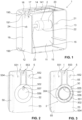
- the instillation line I can be equipped with a liquid container 6, such as the one in the Figure 14 is shown, be connected, in which an instillation liquid is stored.
- the liquid container 6, which can in particular be designed as a bag, can have a hanger 60 in order to hang it, for example, on an infusion stand with respect to the direction of gravity above or next to the peristaltic pump 3.
- a window 141 for a display and control panel is arranged in the area of the upper wall 14 of the pump unit housing 1.
- the display and control panel can be used to display information about the status of the device, such as in particular current pump performance and cycles etc., serve.
- the display and control panel can be designed, for example, as a touch screen.
- FIG. 8 to 13 An embodiment is shown, which differs from that of the embodiment only in the area of the peristaltic pump 3 Figures 1 to 7 differs:
- the coupling between the coupling element 24 and the pump head 30 is not eccentric to the pump head 30 as in the embodiment Figures 1 to 7 , but centrally.
- the coupling takes place via a coupling element 331, which is freely rotatably mounted centrally in a recess 555 on the fluid collection container 5.
- the coupling element 331 is designed as an external square with a substantially square cross section.
- the coupling element 24 provided on the side of the pump unit housing is correspondingly designed as an internal square, so that a rotational movement from the coupling element 24 to the coupling element 331 can be transferred.
- the coupling element 331 is non-rotatable and centrally attached to an inner wheel 33.
- the inner wheel 33 forms a centrally arranged gear of a planetary gear 33, 34 and meshes with three decentrally arranged outer wheels 34, which are also part of the planetary gear 33, 34.
- the outer wheels 34 in turn mesh with the teeth 302 of the ring gear 301.
- the entire planetary gear 33, 34 and the ring gear 301 can be covered from the outside by means of a cover 32. Only the coupling element 331 projects outwards through an opening arranged centrally in the cover 32.
- the outer wheels 34 form the pressure rollers for acting on the instillation line I in order to transport a substance contained therein to the wound area or to a body cavity.
- a peristaltic cassette 7' is arranged as an intermediate part between a fluid collection container 5' and a pump unit housing 1'.
- the peristaltic cassette 7' which thus forms a connecting part, has a housing 71' with a hose guide for the instillation line I, which is guided through the housing 71'.
- the peristaltic cassette 7' serves to connect a secretion line S and an auxiliary line H to the device.
- Essentially all parts of the peristaltic cassette 7 ' are advantageously made by injection molding made of plastic
- the peristaltic cassette 7' has a substantially cuboid, thin outer shape. If the peristaltic cassette 7 'is connected as intended to the pump unit housing 1' and to the fluid collection container 5', as described in the Figure 14 As shown, the fluid collection container 5', the peristaltic cassette 7' and the pump unit housing 1' together form an overall essentially cuboid shape with rounded outer edges and corners. The outer surfaces of the peristaltic cassette 7' are then arranged in alignment with the correspondingly adjacent outer walls of the pump unit housing 1', i.e. with a front wall 10', a rear wall, a first side wall 12', a second side wall, an upper wall 14' and a lower wall .
- the outer surfaces of the peristaltic cassette 7' are each arranged in alignment with the correspondingly adjacent outer walls of the fluid collection container 5', i.e. with a front wall 50', a rear wall, a first side wall 52', a second side wall 53', an upper wall 54' and a lower wall.
- the rear wall, the second side wall and the lower wall of the pump unit housing 1' as well as the rear wall and the lower wall of the fluid collection container 5' cannot be seen in the figures.
- the peristaltic cassette 7' functionally connects the pump unit housing 1' and the fluid collection container 5' to one another by airtightly connecting a housing-side vacuum connection 17' of the pump unit housing 1' to a corresponding container-side vacuum connection 551' provided on the fluid collection container 5'.
- the peristaltic cassette 7' has a vacuum connection 78' facing the fluid collection container 5' and a vacuum connection 79' facing the pump unit housing 1' (see Figure 15 or 18).
- the vacuum connections 78' and 79' are in fluid communication with one another within the peristaltic cassette 7'.
- the peristaltic cassette 7' also has an auxiliary connection 77' ( Figure 18 ), which, when the peristaltic cassette 7' is connected as intended to the pump unit housing 1', is in fluid-tight connection with an auxiliary connection 181' on the pump unit housing 1' provided on the housing side.
- the auxiliary connection 77' is in fluid communication connection within the housing 71' with an auxiliary line connection 74' of the peristaltic cassette 7' ( Figure 15 ), which is used to connect an auxiliary line H.
- the auxiliary line H it is possible to flush the secretion line S if necessary and/or to measure the pressure in the secretion line S.
- the auxiliary line H preferably opens into the secretion line S near the cavity or wound.
- the peristaltic cassette 7' On its side facing the fluid collection container 5', the peristaltic cassette 7' has a secretion connection 76', which is designed for coupling to a container-side secretion connection 552' provided on the fluid collection container 5' and within the housing 71' in fluid-communicating connection with a secretion line connection 73'.
- the secretion line connection 73 ' is used to connect a secretion line S in order to suck body fluids into the fluid collection container 5' via the secretion connections 76' and 552' and to collect them therein.
- a vacuum is generated inside the fluid collection container 5' by means of a vacuum pump arranged in the pump unit housing 1' via the vacuum connections 17', 79', 78' and 551'.
- the housing 71' of the peristaltic cassette 7' On its side facing the pump unit housing 1 ', the housing 71' of the peristaltic cassette 7', as shown in the Figure 18 can be seen, a substantially circular depression 710 ', within which a pump head 30 ' of a peristaltic pump 3 ' is freely rotatable.
- the pump head 30 ' has several pressure rollers 303', which serve to roll on the instillation line 1 placed around the pump head 30' in the recess 710' and to supply a substance to the wound area through the instillation line I by means of mechanical deformation of the hose.
- the pump head 30' In order to transmit the rotational movement of a drive housed in the pump unit housing 1' to the pump head 30', the pump head 30' has a centrally arranged coupling element 331' in the form of a recess.
- the recess has a non-circular shape, which is designed to complement a coupling element 24' arranged on the outside of the pump unit housing 1'.
- the coupling element 24' is attached in a rotationally fixed manner to a drive shaft, which is designed to transmit a rotary movement caused by the drive housed in the pump unit housing 1' to the coupling element 24'.
- a hanging bracket 72' is attached to the peristaltic cassette 1' in order to suspend a liquid container 6 filled with instillation fluid by means of a hanger 60 with respect to the direction of gravity above the peristaltic cassette 1'.
- the instillation line I leading out of the liquid container 6 is passed through a first opening 75' from above into the peristaltic cassette 7', within the recess 710' around the pump head 30' and through a second opening 75' on the front of the peristaltic cassette 7'. led out of this again.
- a company in the Figures 14 to 18 The device shown is also possible without the peristaltic cassette 7 ', for example if only the suction of body fluids is necessary, but not that Supplying a substance.
- the fluid collection container 5' is connected directly to the pump unit housing 1'.
- the coupling element 24' is then arranged in a recess 57' provided within the side wall 53' of the fluid collection container 5', so that any rotational movement of the coupling element 24' remains ineffective.
- the housing-side vacuum connection 17' is coupled directly to the container-side vacuum connection 551'.
- An adapter is inserted between the housing-side auxiliary connection 181' and the container-side secretion connection 551', which has an auxiliary line connection connected to the auxiliary connection 181' and a secretion line connection connected to the secretion connection 551'.
- FIG. 19 An embodiment not according to the invention is in the Figures 19 to 23 shown, in which not only a fluid collection container 5" can be fixed to and connected to a pump unit housing 1", but also a further connecting part in the form of an instillation container 4".
- the pump unit housing 1" is designed similarly to that of Figure 1 and differs from this in particular in that the front wall 10" and the rear wall 11" protrude with their vertical wall edges not only towards one side, but towards both sides of the side wall arranged between them.
- the fluid collection container 5" is held between the wall edges of the front wall 10" and the rear wall 11" and on the other side the instillation container 4".
- An upper wall 14" of the pump unit housing 1" has a window 141" for a display and control panel for operating and displaying the operating status of the device.
- the fluid collection container 5" has a largely identical design with a base part 55" and a transparent part 56" as that in the Figures 1 to 7 embodiment shown.
- the fluid collection container 5" can be attached to the pump unit housing 1" by means of several pins 412". In contrast to the fluid collection container Figures 1 to 7 In the present case, however, no pump head is integrated in the fluid collection container 5".
- the secretion line S and the auxiliary line H are guided to the outside through the fluid collection container 5".
- the instillation container 4" which is advantageously made largely entirely of plastic by injection molding and serves to provide an instillation liquid, has a similar design to the fluid collection container 5". It has a transparent part 40", which is provided with a filling level scale 401", and a base part 41" made of an opaque material.
- An annular recess 43" is formed within the side surface of the instillation container 4" facing the pump unit housing 1", within which a ring gear 301" is arranged ( Figure 21 ).
- the ring gear 301 on which pressure rollers rotatable about roller axes 304" are attached, forms a pump head 30" of a peristaltic pump 3".
- the ring gear 301" is freely rotatable on a bearing pin 410" provided concentrically within the annular recess 43".
- the bearing pin 410" has a recess 411" which is open in the radial direction towards the recess 43".
- the recess 43" and the ring gear 301" are covered from the outside by means of a cover 32".
- the hose guide is fed through a feed channel extending from the opening 42" to the annular recess 43", the annular recess 43" and a channel leading away from the recess 43" upwards.
- the installation line 1 is placed around the pump head 30" in such a way that when the pump head 30" is rotated, the installation line I by means of the pressure rollers are mechanically deformed and the instillation fluid is thereby pumped out of the instillation container 4" and towards the wound area.
- a vent opening 44" is also provided on the base part 41" in order to admit outside air into the instillation container 4" if the amount of instillation liquid in the instillation container 4" becomes smaller during operation of the device.
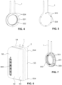
- FIGS 24 to 27 show a further embodiment of a device according to the invention, in which the pump head 30′′′ of a peristaltic pump 3′′′, in contrast to that in the Figures 1 to 23 shown embodiments is not integrated in a connecting part, but in the pump unit housing 1′′′.
- Fluid collection container 5′′′ can be connected, which has a hose guide 559′′′ for guiding an instillation line I, so that the hose inserted into the hose guide 559′′′ forms a peristaltic pump 3′′′ in combination with the pump head 30′′′.
- a motor 20′′′ of a drive train 2′′′ is arranged in the interior 16′′′ of the pump unit housing 1′′′, which serves to drive the pump head 30′′′ which is firmly attached to a motor shaft.
- a diaphragm pump 80′′′ and a drive 81′′′ for driving this diaphragm pump 80′′′ are arranged in the interior 16′′′.
- the drives 20′′′ and 81′′′ are supplied with electrical energy by means of an accumulator 82′′′, which is also arranged in the interior 16′′′.
- the diaphragm pump 80'" is used to suction body fluids by generating a vacuum in the fluid collection container 5'" via a vacuum connection 17′′′ provided on the pump unit housing 1′′′, which is connected to a vacuum connection 551′′′ of the fluid collection container 5′′′.
- the body fluids are thereby sucked through a secretion line S into the interior of the fluid collection container 5′′′ and collected there.
- the pump unit housing 1′′′ has an upper wall 14′′′ with a window 141'" for arranging a display and control panel.
- a side wall 12′′′ rests flat on the fluid collection container 5′′′ when it is connected to the pump unit housing 1′′′ as intended.
- the pump unit housing 1′′′ also has a housing-side auxiliary connection 181′′′, which, when the fluid collection container 5′′′ is attached to the pump unit housing 1′′′, is coupled to a container-side auxiliary connection 558′′ provided on the fluid collection container 5′′′ in order to be in a fluid-communicating connection with an auxiliary line H
- the auxiliary line H is used to flush and/or measure the pressure or flow rate of the secretion line S.
- the pump head 30′′′ to which several pressure rollers 303′′′ are freely rotatably attached, is arranged in such a way that at least a region of its peripheral surface causes a mechanical deformation of the instillation line I during operation when it is inserted into the hose guide 559′′ of the fluid collection container 5′′′ is inserted and the fluid collection container 5′′′ is connected as intended to the pump unit housing 1′′′.
- the pump head 30'" can be exposed with at least part of its peripheral surface, or, as is the case in the present embodiment, there by a flexible cover membrane 121′′′ be covered to prevent dirt particles from entering the pump head 30′′′ and the interior 16′′′.
- the pump unit housing 1' has a step, the upward-facing surface of which is penetrated by the pump head 30′′′.
- the step enables the pump head 30′′′ to be positioned with an area of its peripheral surface on the hose guide 559 ′′′ inserted installation line I.
- the pump unit housing 1′′′ and the fluid collection container 5′′ connected to it as intended have an essentially cuboid external shape. Due to the step, the front wall 10′′′ and the rear wall of the pump unit housing 1′′′, which is not visible in the figures, are each L-shaped.
- the fluid collection container 5′′′ has a first side wall 52′′′ and a second side wall 53′′′ facing the pump unit housing 1′′′, which is projected beyond by an upper projecting region 59′′′, which also forms an upper wall 54′′′, in the direction of the pump unit housing 1′′′ .
- a circular segment-like recess is provided, which forms the hose bed of the instillation line I in the peristaltic pump 3′′′ and thus the hose guide 559′′′.
- a substance can be conveyed through the instillation line 1 to the wound area or to a body cavity by means of the peristaltic pump 3′′′.
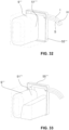
- FIG. 28 to 33 A further embodiment of a device according to the invention is shown with a pump unit housing 1 ⁇ and a connecting part in the form of a fluid collection container 5"" which can be connected to it.
- the fluid collection container 5"" has a cuboid external shape with a base part 55 ⁇ and an advantageously transparent part 56"".
- the base part 55"" forms a cover that can be removed from the transparent part 56 ⁇ and which forms the entire side surface of the fluid collection container 5"" facing the pump unit housing 1 ⁇ .
- the base part 55"" is advantageously manufactured as a whole and essentially completely from a plastic using an injection molding process.
- the vacuum line leading from a vacuum pump housed in the pump unit housing 1 ⁇ into the interior of the fluid collection container 5"" extends via a housing-side Vacuum connection 17"" and a container-side vacuum connection 551"" through the base part 55"" when the fluid collection container 5"" is connected to the pump unit housing 1 ⁇ as intended.
- a secretion line S opens into the interior of the fluid collection container 5"" via the base part 55"".
- an auxiliary line H leads into the pump unit housing 1 ⁇ via a container-side auxiliary connection 558 ⁇ formed on the base part 55" and via a housing-side auxiliary connection 181"" into the pump unit housing 1 ⁇ when the fluid collection container 5"" is connected to the pump unit housing 1 ⁇ .
- the auxiliary line H is used for flushing if necessary and/or measurement of the pressure of the secretion line S.
- the base part 55"" has a recess on its side facing the pump unit housing 1"", which is traversed by the hose of an instillation line I.
- the depression forms the hose bed and thus a hose guide 559 ⁇ of a peristaltic pump 3"" when the fluid collection container 5"" is connected to the pump unit housing 1"" as intended.
- the pump unit housing 1 ⁇ shown is the pump head 30"" of the peristaltic pump 3"" of this device, which projects at least part of its peripheral surface through a corresponding side wall of the pump unit housing 1 ⁇ outwards towards the fluid collecting container 5 ⁇ .
- This protruding part of the pump head 30"" from which in the Figure 29 only the pressure rollers 303 ⁇ are drawn, can, as in the present case, be covered by a flexible cover membrane 121"".
- the pump head 30"" projects into the recess of the base part 55"" forming the hose guide 559 ⁇ and presses the instillation line I there against the base part 55"".
- the instillation line I guided in the hose guide 559"" opens via an opening 42"" into a flexible liquid bag 9 ⁇ arranged in the interior 51"" of the fluid collection container 5"".
- Instillation liquid is provided in the liquid bag 9"", which can be fed to the body through the instillation line 1 by means of the peristaltic pump 3"".
- the fluid collection container 5"" increasingly fills with suctioned fluid, and the volume of the fluid bag 9"” is reduced by the fluid supplied to the body.
- the liquid bag 9 ⁇ can be emptied or filled without the base part 55"" being separated from the transparent part 56 ⁇ must be removed.
- the drives accommodated can in particular each be a brushless DC motor.
- An accumulator can be provided in the pump unit housing 1, 1', 1", 1" or 1"" in order to supply the drive with electrical power.
- the drive train between the drive and the pump head of the peristaltic pump can also have one or more have several gears in order to adapt the rotational speed of the pump head to that of the drive. It is also possible to arrange a freewheel in the drive train in order to only drive the pump head when the drive has a certain direction of rotation.
Description
Die vorliegende Erfindung betrifft eine Vorrichtung zum Absaugen von Körperfluiden und zum Zuführen einer Substanz zu einem menschlichen oder tierischen Körper sowie ein Anschlussteil einer derartigen Vorrichtung. Derartige Vorrichtungen werden insbesondere im medizinischen Bereich verwendet, beispielsweise in der mit Instillation oder Irrigation kombinierten Unterdruck-Wundtherapie, in der Augenchirurgie oder bei der Fettabsaugung.The present invention relates to a device for suctioning off body fluids and for supplying a substance to a human or animal body, as well as a connecting part of such a device. Such devices are used in particular in the medical field, for example in negative pressure wound therapy combined with instillation or irrigation, in eye surgery or in liposuction.
Im medizinischen Bereich gibt es vielfältige Anwendungen, bei denen einerseits Körperfluide oder Sekrete aus Körperkavitäten oder Wunden mittels einer Pumpe abgesaugt und andererseits eine Substanz dem Körper zugeführt werden. Mögliche Anwendungsgebiete betreffen insbesondere die mit Instillation kombinierte Unterdruck-Wundtherapie, die Augenchirurgie und die Liposuktion (Fettabsaugung). Je nach Anwendung erfolgen die Absaugung und die Zuführung dabei gleichzeitig, nacheinander und/oder abwechslungsweise intermittierend.There are a variety of applications in the medical field in which, on the one hand, body fluids or secretions are sucked out of body cavities or wounds using a pump and, on the other hand, a substance is supplied to the body. Possible areas of application particularly concern negative pressure wound therapy combined with instillation, eye surgery and liposuction (liposuction). Depending on the application, the suction and feeding take place simultaneously, one after the other and/or alternately intermittently.
Bei der zuzuführenden Substanz kann es sich beispielsweise um eine physiologische oder nicht physiologische Kochsalzlösung, ein Arzneimittel oder um ein Gemisch davon handeln. Die Substanz kann zum Beispiel zur Förderung der Wundheilung, zur Verhinderung von Infektionen oder zur lokalen Anästhesie dienen. Das Zuführen der Substanz kann somit zur Spülung oder therapeutischen, diagnostischen und/oder präventiven Zwecken dienen.The substance to be supplied can be, for example, a physiological or non-physiological saline solution, a drug or a mixture thereof. The substance can be used, for example, to promote wound healing, to prevent infections or for local anesthesia. The supply of the substance can therefore serve for flushing or therapeutic, diagnostic and/or preventive purposes.
Oft wird zum Zuführen der Substanz ähnlich wie bei der herkömmlichen Infusion ein mit der zuzuführenden Substanz gefüllter Flüssigkeitsbeutel oder eine Flasche erhöht über der zu behandelnden Körperstelle angeordnet, so dass die Substanz aufgrund des hydrostatischen Druckes durch eine Zuführleitung der zu behandelnden Stelle zugeführt wird. Separat dazu werden die Körperfluide von einer Vakuumpumpe via einer entsprechenden Leitung abgesaugt.To supply the substance, similar to conventional infusion, a liquid bag or bottle filled with the substance to be supplied is often placed elevated above the body area to be treated, so that the substance is supplied to the area to be treated through a supply line due to the hydrostatic pressure. Separately, the body fluids are sucked out by a vacuum pump via a corresponding line.
Um eine bessere Einstellung und Regelung beim Zuführen der Substanz zu ermöglichen, und/oder um unabhängig von der Anordnung und insbesondere der Höhenlage des mit der Substanz gefüllten Flüssigkeitsbehälters zu sein, sind auch Systeme hinlänglich bekannt, bei denen die Zuführung der Substanz zum Körper mittels einer Pumpe, insbesondere einer sog. Peristaltik- oder Schlauchpumpe erfolgt.In order to enable better adjustment and regulation when supplying the substance, and/or to be independent of the arrangement and in particular the height of the liquid container filled with the substance, systems are also well known in which the substance is supplied to the body by means of a Pump, in particular a so-called peristaltic or hose pump.
Beispielsweise offenbart die
Die
Die
In der
Diese Vorrichtungen, welche einerseits zum Absaugen von Körperfluiden sowie andererseits zum Zuführen einer Substanz dienen, sind auf bestimmte Anwendungen eingeschränkt und zudem meist aufwändig und entsprechend kostenintensiv in der Herstellung.These devices, which are used on the one hand to suck out body fluids and on the other hand to supply a substance, are limited to certain applications and are also usually complex and correspondingly expensive to produce.
Die
In den Dokumenten
Weitere gattungsgemässe Vorrichtungen sind zum Beispiel in der
Die
Es ist deshalb eine Aufgabe der Erfindung, eine vielseitig verwendbare Vorrichtung zum Absaugen von Körperfluiden und zum Zuführen einer Substanz zu einem menschlichen oder tierischen Körper zu schaffen, welche zudem günstig herstellbar ist. Die Vorrichtung sollte ausserdem für den Anwender einfach handhabbar sein.It is therefore an object of the invention to create a versatile device for suctioning body fluids and supplying a substance to a human or animal body, which can also be produced inexpensively. The device should also be easy to handle for the user.
Zur Lösung dieser Aufgabe wird eine Vorrichtung vorgeschlagen, wie sie im Anspruch 1 angegeben sind. Ausserdem wird im Anspruch 9 ein Anschlussteil einer derartigen Vorrichtung angegeben. Vorteilhafte Ausgestaltungen der Erfindung sind in den abhängigen Ansprüchen angegeben.To solve this problem, a device is proposed, as specified in
Die vorliegende Erfindung stellt also eine Vorrichtung zum Absaugen von Körperfluiden und zum Zuführen einer Substanz zu einem menschlichen oder tierischen Körper zur Verfügung, aufweisend
- eine Antriebseinheit mit einem Antrieb,
- einen vom Antrieb antreibbaren Pumpenkopf, sowie
- ein lösbar, das heisst bevorzugt ohne Zuhilfenahme eines Werkzeugs, an die Antriebseinheit anschliessbares Anschlussteil mit einer Schlauchführung, welche derart zur Aufnahme eines Schlauches ausgebildet ist, dass der Schlauch, wenn das Anschlussteil bestimmungsgemäss an der Antriebseinheit angeschlossen ist, in Kombination mit dem Pumpenkopf eine Peristaltikpumpe bildet, mit welcher die fluide Substanz durch den Schlauch hindurch zum menschlichen oder tierischen Körper beförderbar ist.
- a drive unit with a drive,
- a pump head that can be driven by the drive, as well as
- a connecting part that can be connected to the drive unit in a detachable manner, that is to say preferably without the aid of a tool, with a hose guide which is designed to accommodate a hose such that the hose, when the connecting part is connected to the drive unit as intended, forms a peristaltic pump in combination with the pump head forms, with which the fluid substance can be transported through the hose to the human or animal body.
Beim Anschlussteil handelt es sich um einen Fluidsammelbehälter zum Sammeln der abgesaugten Körperfluide oder um ein Teil eines solchen Fluidsammelbehälters zum Sammeln der abgesaugten Körperfluide oder um ein Zwischenteil, welches an einen solchen Fluidsammelbehälter zum Sammeln der abgesaugten Körperfluide anschliessbar ist, um eine Verbindung zwischen der Antriebseinheit und dem Fluidsammelbehälter herzustellen. Im Falle eines Zwischenteils dient dieses also insbesondere dazu, den Fluidsammelbehälter funktionell mit der Antriebseinheit zu verbinden.The connecting part is a fluid collection container for collecting the aspirated body fluids or a part of such a fluid collection container for collecting the aspirated body fluids or an intermediate part which is connected to such a fluid collection container Collecting the suctioned body fluids can be connected to establish a connection between the drive unit and the fluid collection container. In the case of an intermediate part, this serves in particular to functionally connect the fluid collection container to the drive unit.
Die Antriebseinheit weist ein Gehäuse auf, in welchem der Pumpenkopf angeordnet ist. Erfindungsgemäß ist vorgesehen, dass der Pumpenkopf zumindest mit einem Teil seiner Umfangsfläche durch eine Seitenwand des Gehäuses hindurch nach haussen zum Anschlussteil hin vorragt oder das Gehäuse im Bereich des Pumpenkopfes eine Stufe mit einer Fläche aufweist, die vom Pumpenkopf durchragt wird.The drive unit has a housing in which the pump head is arranged. According to the invention, it is provided that the pump head projects at least part of its peripheral surface through a side wall of the housing towards the connecting part or that the housing has a step in the area of the pump head with a surface through which the pump head protrudes.
Der Pumpenkopf kann im Anschlussteil integriert sein. Falls der Pumpenkopf im Anschlussteil integriert ist, kann, da der Fluidsammelbehälter üblicherweise nach einer gewissen Benutzungsdauer, oft sogar nach einmaligem Gebrauch, entsorgt bzw. ausgewechselt wird, bei einer Ausbildung des Anschlussteils als Fluidsammelbehälter bzw. als Teil davon sichergestellt werden, dass auch der Pumpenkopf bereits dann ersetzt wird. Die Anforderungen zur Herstellung des Pumpenkopfes werden dadurch erheblich verringert, so dass die Vorrichtung insgesamt günstiger herstellbar ist.The pump head can be integrated in the connection part. If the pump head is integrated in the connection part, since the fluid collection container is usually disposed of or replaced after a certain period of use, often even after a single use, it can be ensured that the pump head is also designed when the connection part is designed as a fluid collection container or as part thereof will then be replaced. The requirements for producing the pump head are thereby significantly reduced, so that the device can be manufactured more cheaply overall.
Der Pumpenkopf kann im Anschlussteil integriert sein, und die Antriebseinheit kann ein mit dem Antrieb verbundenes Kopplungselement aufweisen, welches den Pumpenkopf an den Antrieb koppelt, wenn das Anschlussteil bestimmungsgemäss an der Antriebseinheit angeschlossen ist. Beim Anschliessen des Anschlussteils an die Antriebseinheit kommt der Pumpenkopf dann derart im Bereich der Schlauchführung zu liegen, dass er in Kombination mit einem in die Schlauchführung eingelegten Schlauch eine Peristaltikpumpe bildet. Der Pumpenkopf kann unabhängig davon im Anschlussteil integriert sein und die Antriebseinheit kann unabhängig davon ein mit dem Antrieb verbundenes Kopplungselement zur Koppelung des Pumpenkopfes an den Antrieb aufweisen, ob das Anschlussteil als Fluidsammelbehälter, als Teil eines Fluidsammelbehälters oder als Zwischenteil ausgebildet ist oder nicht.The pump head can be integrated in the connecting part, and the drive unit can have a coupling element connected to the drive, which couples the pump head to the drive when the connecting part is connected to the drive unit as intended. When connecting the connecting part to the drive unit, the pump head then comes to lie in the area of the hose guide in such a way that it forms a peristaltic pump in combination with a hose inserted into the hose guide. The pump head can be integrated in the connection part independently of this and the drive unit can have a coupling element connected to the drive for coupling the pump head to the drive regardless of whether the connection part is designed as a fluid collection container, as part of a fluid collection container or as an intermediate part or not.
Bei einer Integration des Pumpenkopfes im Anschlussteil ist die Vorrichtung wesentlich vielseitiger verwendbar. So können zum Beispiel verschiedenartige Anschlussteile mit unterschiedlichen Pumpenköpfen an dieselbe Antriebseinheit angeschlossen werden. Der Pumpenkopf kann bzgl. seiner Dimensionierung und Ausgestaltung spezifisch an das jeweilige Anschlussteil angepasst sein. Die Anschlussteile können zum Beispiel unterschiedliche Substanzen enthalten und/oder für unterschiedliche Anwendungen dienen. Mittels entsprechender Auslegung des Pumpenkopfes können unterschiedliche Erfordernisse problemlos und unter Verwendung von immer derselben Antriebseinheit erfüllt werden.If the pump head is integrated into the connecting part, the device can be used in a much more versatile manner. For example, different types of connecting parts with different pump heads can be connected to the same drive unit. The pump head can be specifically adapted to the respective connection part in terms of its dimensions and design. The connecting parts can, for example, contain different substances and/or serve for different applications. By appropriately designing the pump head, different requirements can be met easily and always using the same drive unit.
Des Weiteren sind die Anforderungen an das Anschlussteil bzgl. dessen Lebensdauer oft weniger hoch als die entsprechenden Anforderungen an die Antriebseinheit. Bei einer Integration des Pumpenkopfes im Anschlussteil gelten die geringeren Anforderungen bzgl. Lebensdauer auch für den Pumpenkopf, welcher somit erheblich günstiger herstellbar ist, als bei einer Vorrichtung mit einem in der Antriebseinheit integriertem Pumpenkopf.Furthermore, the requirements for the connecting part in terms of its service life are often less stringent than the corresponding requirements for the drive unit. When integrating the Pump head in the connecting part, the lower requirements with regard to service life also apply to the pump head, which is therefore considerably cheaper to produce than with a device with a pump head integrated in the drive unit.
Die erfindungsgemässe Vorrichtung wird für medizinische Zwecke eingesetzt, insbesondere zu der mit Instillation oder Irrigation kombinierten Unterdruckbehandlung von Wunden am menschlichen oder tierischen Körper. Andere Anwendungsgebiete sind jedoch möglich, beispielsweise die kombinierte Fettabsaugung und Spülung bei der Liposuktion oder das Spülen von Kathetern zur Vermeidung von Verstopfungen oder die kombinierte Absaugung und Spülung bei der Augenchirurgie.The device according to the invention is used for medical purposes, in particular for the negative pressure treatment of wounds on the human or animal body combined with instillation or irrigation. However, other areas of application are possible, for example combined liposuction and irrigation in liposuction or the irrigation of catheters to avoid blockages or combined suction and irrigation in eye surgery.
Die Vorrichtung ist bevorzugt zum gleichzeitigen Absaugen von Körperfluiden und Zuführen einer Substanz geeignet.The device is preferably suitable for simultaneously suctioning off body fluids and supplying a substance.
Peristaltikpumpen sind auch unter dem Begriff Schlauchpumpen bekannt und eignen sich besonders gut um auch geringe Fluidvolumina einer Substanz, insbesondere einer fluiden Substanz wie einer Flüssigkeit, kontrolliert zum Körper zu befördern. Bei Peristaltikpumpen kann zudem eine Kontamination der fluiden Substanz und der Vorrichtung ausgeschlossen werden. Eine Peristaltikpumpe weist in der Regel zumindest einen drehbar gelagerten Pumpenkopf sowie ein in einem Schlauchbett gelagerten Schlauch auf. In der Regel bildet die Schlauchführung das Schlauchbett der Peristaltikpumpe. Am Pumpenkopf sind üblicherweise zum Beispiel Anpressrollen oder Gleitschuhe angebracht, welche bei einer Drehung des Pumpenkopfes den im Schlauchbett gelagerten Schlauch mechanisch verformen und dadurch eine Substanz durch den Schlauch hindurch befördern.Peristaltic pumps are also known as peristaltic pumps and are particularly suitable for conveying even small fluid volumes of a substance, in particular a fluid substance such as a liquid, to the body in a controlled manner. With peristaltic pumps, contamination of the fluid substance and the device can also be ruled out. A peristaltic pump usually has at least one rotatably mounted pump head and a hose mounted in a hose bed. As a rule, the hose guide forms the hose bed of the peristaltic pump. For example, pressure rollers or sliding shoes are usually attached to the pump head, which mechanically deform the hose stored in the hose bed when the pump head rotates and thereby transport a substance through the hose.
Beispielsweise kann eine Instillationsleitung in die am Anschlussteil ausgebildete Schlauchführung derart eingelegt werden, dass sie zumindest teilweise um den Pumpenkopf herum geführt ist, so dass dieser den Schlauch der Instillationsleitung mechanisch verformen und eine darin enthaltene Substanz befördern kann. Die Substanz kann zum Beispiel in einem oberhalb der Peristaltikpumpe angeordneten Flüssigkeitsbeutel oder in einer entsprechend angeordneten Flasche gelagert sein und daraus zugeführt werden.For example, an instillation line can be inserted into the hose guide formed on the connecting part in such a way that it is at least partially guided around the pump head, so that it can mechanically deform the hose of the instillation line and transport a substance contained therein. The substance can, for example, be stored in a liquid bag arranged above the peristaltic pump or in a correspondingly arranged bottle and supplied therefrom.
Beim Antrieb handelt es sich in der Regel um einen Motor, insbesondere um einen Elektromotor. In einer insbesondere bevorzugten Ausführungsform handelt es sich um einen bürstenlosen Gleichstrommotor, da ein solcher in der Regel bei tiefen Drehzahlen von weniger als 100U/min betrieben werden kann. Ein bürstenloser Gleichstrommotor lässt zudem eine Druckregelung mit relativ kleiner Amplitude zu, wodurch eine sehr genaue Steuerung des Druckes (Unterdruck oder Überdruck) möglich wird.The drive is usually a motor, especially an electric motor. In a particularly preferred embodiment, it is a brushless DC motor, since such a motor can usually be operated at low speeds of less than 100 rpm. A brushless DC motor also allows for pressure control relatively small amplitude, which makes very precise control of the pressure (negative pressure or positive pressure) possible.
Beim Anschlussteil kann es sich auch um einen Behälter handeln, der sowohl zum Sammeln der abgesaugten Körperfluide als auch zur Bereitstellung der fluiden Substanz dient. Üblicherweise ist dann eine Instillationsleitung, welche in das Innere des Behälters mündet und somit aus diesem herausführt, in die am Anschlussteil vorgesehene Schlauchführung eingelegt, so dass mittels der Peristaltikpumpe die fluide Substanz durch die Instillationsleitung aus dem Instillationsbehälter heraus beförderbar ist.The connecting part can also be a container that serves both to collect the suctioned body fluids and to provide the fluid substance. Usually, an instillation line, which opens into the interior of the container and thus leads out of it, is then inserted into the hose guide provided on the connecting part, so that the fluid substance can be conveyed out of the instillation container through the instillation line by means of the peristaltic pump.
Ein Behälter, der sowohl zum Sammeln der abgesaugten Körperfluide als auch zur Bereitstellung der fluiden Substanz dient, weist bevorzugt einen Innenraum auf, der in einen ersten Bereich zum Sammeln der abgesaugten Körperfluide sowie in einen zweiten Bereich zur Bereitstellung der fluiden Substanz unterteilt ist. Die beiden Bereiche können mittels einer starren Trennwand voneinander getrennt sein. Bevorzugt sind sie jedoch mittels einer flexibel ausgebildeten Trennwand voneinander getrennt. Der Behälter kann insbesondere ein kombinierter Fluidsammel- und Instillationsbehälter sein. Die flexibel ausgebildete Trennwand bewirkt, dass eine Verkleinerung des zweiten Bereiches unmittelbar eine Vergrösserung des ersten Bereiches bewirkt. Das Gesamtvolumen des Innenraums, welches vorteilhaft im Wesentlichen der Summe der Volumen des ersten und des zweiten Bereiches entspricht, bleibt dabei konstant. Im laufenden Betrieb der Vorrichtung füllt sich der erste Bereich üblicherweise allmählich mit den abgesaugten Körperfluiden. Während des Zuführens der fluiden Substanz zum Körper leert sich der zweite Bereich allmählich, wodurch sich sein Volumen verringert. Die flexiblen Volumina des ersten und des zweiten Bereiches ermöglichen eine erhebliche Platzeinsparung im Vergleich zum Beispiel zu einer Lösung mit einem ersten starr ausgebildeten Behälter zum Sammeln der abgesaugten Körperfluide sowie einem zweiten starr ausgebildeten Behälter zur Bereitstellung der fluiden Substanz. Im Idealfall, wenn die fluide Substanz schneller oder gleich schnell aus dem Behälter abgeführt wird wie Körperfluide angesaugt werden, kann das Volumen des Behälters dadurch sogar halbiert werden.A container, which serves both to collect the aspirated body fluids and to provide the fluid substance, preferably has an interior that is divided into a first area for collecting the aspirated body fluids and a second area for providing the fluid substance. The two areas can be separated from each other by means of a rigid partition. However, they are preferably separated from one another by means of a flexible partition wall. The container can in particular be a combined fluid collection and instillation container. The flexible partition wall causes a reduction in the second area to immediately increase the size of the first area. The total volume of the interior, which advantageously essentially corresponds to the sum of the volumes of the first and second areas, remains constant. During ongoing operation of the device, the first area usually gradually fills with the sucked-out body fluids. As the fluid substance is delivered to the body, the second region gradually empties, thereby reducing its volume. The flexible volumes of the first and second areas enable significant space savings compared, for example, to a solution with a first rigid container for collecting the suctioned body fluids and a second rigid container for providing the fluid substance. Ideally, if the fluid substance is removed from the container faster or at the same speed as body fluids are sucked in, the volume of the container can even be halved.
Der erwähnte Behälter mit einem Innenraum, der mittels einer flexiblen Trennwand in einen ersten Bereich zum Sammeln der abgesaugten Körperfluide sowie in einen zweiten Bereich zur Bereitstellung der fluiden Substanz unterteilt ist, stellt eine weitere unabhängige Erfindung dar. Ein derartiger Behälter kann auch bei herkömmlichen Vorrichtungen, insbesondere herkömmlichen Instillations- oder Irrigationsvorrichtungen, eingesetzt werden, bei welchen einerseits Körperfluide abgesaugt und andererseits eine fluide Substanz einem menschlichen oder tierischen Körper zugeführt wird. Der Behälter muss nicht zwingend eine Schlauchführung, welche mit einem Pumpenkopf zusammenwirkt, aufweisen. Der Behälter kann zum Beispiel auch nur via Schlauchverbindungen an ein Pumpaggregat angeschlossen werden, und die fluide Substanz kann auch ohne die Hilfe einer Pumpe dem Körper zugeführt werden, indem zum Beispiel mittels Anordnung des Behälters oberhalb des Körpers die Schwerkraft ausgenutzt wird.The mentioned container with an interior, which is divided by means of a flexible partition into a first area for collecting the suctioned body fluids and a second area for providing the fluid substance, represents a further independent invention. Such a container can also be used in conventional devices, in particular conventional instillation or irrigation devices, in which, on the one hand, body fluids are sucked out and, on the other hand, a fluid substance is sucked out of a human or animal body is supplied. The container does not necessarily have to have a hose guide that interacts with a pump head. The container can, for example, only be connected to a pump unit via hose connections, and the fluid substance can also be supplied to the body without the help of a pump, for example by taking advantage of gravity by arranging the container above the body.
Vorteilhaft wird die flexible Trennwand durch einen im Innenraum angeordneten Beutel gebildet. Der Beutel trennt dann also den ersten Bereich vom zweiten Bereich. Bevorzugt begrenzt der Beutel den ersten oder den zweiten Bereich, vorzugsweise jedoch den zweiten Bereich, zu einem überwiegenden Grossteil. Der Beutel dient dann also vorzugsweise zur Bereitstellung der fluiden Substanz.The flexible partition is advantageously formed by a bag arranged in the interior. The bag then separates the first area from the second area. The bag preferably delimits the first or second area, but preferably the second area, to a large extent. The bag then preferably serves to provide the fluid substance.
Der Behälter, welcher sowohl zum Sammeln der abgesaugten Körperfluide als auch zur Bereitstellung der fluiden Substanz dient und zwei mittels einer flexiblen Trennwand getrennte Bereiche hat, weist vorteilhaft einen Vakuumanschluss zum Anschliessen einer Vakuumleitung auf, um im ersten Bereich des Innenraums ein Vakuum zu erzeugen. Ausserdem weist der Behälter vorteilhaft einen Sekretleitungsanschluss zum Anschliessen einer zum menschlichen oder tierischen Körper führenden Sekretleitung auf, um mittels des im ersten Bereich des Innenraums erzeugten Vakuums die Körperfluide durch die Sekretleitung hindurch in den ersten Bereich hinein zu saugen. Des Weiteren weist der Behälter vorzugsweise einen Anschluss zum Anschliessen einer Zuführleitung auf, um die fluide Substanz vom zweiten Bereich des Innenraums aus durch die Zuführleitung hindurch dem menschlichen oder tierischen Körper zuzuführen.The container, which serves both to collect the suctioned body fluids and to provide the fluid substance and has two areas separated by a flexible partition, advantageously has a vacuum connection for connecting a vacuum line in order to generate a vacuum in the first area of the interior. In addition, the container advantageously has a secretion line connection for connecting a secretion line leading to the human or animal body in order to suck the body fluids through the secretion line into the first area by means of the vacuum generated in the first area of the interior. Furthermore, the container preferably has a connection for connecting a supply line in order to supply the fluid substance to the human or animal body from the second area of the interior through the supply line.
Insbesondere wenn es sich beim Anschlussteil um einen kombinierten Fluidsammel- und Instillationsbehälter handelt, aber auch in anderen Fällen, können das Anschlussteil ein Identifikationsmerkmal und die Antriebseinheit eine Identifikationseinheit aufweisen, um zu identifizieren, welche Art eines Anschlussteils an der Antriebseinheit angeschlossen ist. Die Antriebseinheit kann dann insbesondere dazu ausgebildet sein, in Abhängigkeit des identifizierten Anschlussteils einen von mehreren möglichen Betriebsmodi zum Antreiben der Peristaltikpumpe auszuwählen oder vorauszuwählen. Im Falle, dass es sich beim Anschlussteil um einen kombinierten Fluidsammel- und Instillationsbehälter handelt, kann das Identifikationsmerkmal insbesondere zur Identifikation der Art der im Behälter enthaltenen Substanz dienen.In particular if the connection part is a combined fluid collection and instillation container, but also in other cases, the connection part can have an identification feature and the drive unit can have an identification unit in order to identify which type of connection part is connected to the drive unit. The drive unit can then be designed in particular to select or preselect one of several possible operating modes for driving the peristaltic pump depending on the identified connection part. If the connecting part is a combined fluid collection and instillation container, the identification feature can serve in particular to identify the type of substance contained in the container.
In einer insbesondere bevorzugten Ausführungsform handelt es sich beim Anschlussteil um ein Wegwerfteil, das für einen einmaligen Gebrauch ausgelegt ist und vorteilhaft im Wesentlichen vollständig aus Spritzgussteilen hergestellt ist. Bei einem Wegwerfteil, welches nach einer gewissen Zeit ausgetauscht und entsorgt wird, zum Beispiel wenn der Fluidsammelbehälter voll oder der Instillationsbehälter leer ist, sind die Anforderungen insbesondere an einen allfällig darin integrierten Pumpenkopf verhältnismässig gering. Die Herstellungskosten für die gesamte Vorrichtung können dadurch erheblich gesenkt werden im Vergleich zu einer Vorrichtung, bei welcher der Pumpenkopf im oder am Pumpaggregatgehäuse angeordnet ist und dadurch für eine viel längere Lebensdauer ausgelegt sein muss.In a particularly preferred embodiment, the connecting part is a disposable part that is designed for one-time use and is advantageously made essentially entirely from injection molded parts. For a disposable part that is after a... is replaced and disposed of after a certain period of time, for example when the fluid collection container is full or the instillation container is empty, the requirements, in particular for any pump head integrated therein, are relatively low. The manufacturing costs for the entire device can thereby be significantly reduced compared to a device in which the pump head is arranged in or on the pump unit housing and must therefore be designed for a much longer service life.
Um die Drehgeschwindigkeit des Pumpenkopfes gegenüber derjenigen des Antriebs anzupassen, kann ein Getriebe, insbesondere ein Planetengetriebe vorgesehen sein, via welches der Pumpenkopf an den Antrieb gekoppelt ist, wenn das Anschlussteil bestimmungsgemäss an der Antriebseinheit angeschlossen ist. Das Getriebe kann insbesondere im Anschlussteil integriert sein.In order to adapt the rotational speed of the pump head to that of the drive, a gear, in particular a planetary gear, can be provided, via which the pump head is coupled to the drive when the connecting part is connected to the drive unit as intended. The gearbox can in particular be integrated in the connecting part.
Die Antriebseinheit kann ausserdem eine Vakuumpumpe, insbesondere eine Membranpumpe, aufweisen, welche zum Absaugen der Körperfluide dient. Vorteilhaft bildet die Vakuumpumpe einen Teil der Antriebseinheit. Eine Membranpumpe weist in der Regel zumindest eine Membran sowie eine von dieser begrenzte Pumpkammer auf.The drive unit can also have a vacuum pump, in particular a membrane pump, which is used to suck out the body fluids. The vacuum pump advantageously forms part of the drive unit. A membrane pump usually has at least one membrane and a pump chamber delimited by it.
Die Antriebseinheit weist bevorzugt ein Gehäuse auf, in welchem sowohl der Antrieb als auch die Vakuumpumpe angeordnet sind. Das Kopplungselement ist vorteilhaft auf einer Aussenseite des Gehäuses angeordnet.The drive unit preferably has a housing in which both the drive and the vacuum pump are arranged. The coupling element is advantageously arranged on an outside of the housing.
In einer bevorzugten Ausführungsform dient derselbe Antrieb, welcher zum Antreiben der Peristaltikpumpe dient, auch zum Antreiben der Vakuumpumpe. Indem derselbe Antrieb zum Antreiben von beiden Pumpen dient, kann die Vorrichtung insgesamt kleiner dimensioniert werden und zudem ein geringeres Gewicht aufweisen. Die Vorrichtung kann dadurch insbesondere derart ausgebildet werden, dass sie tragbar ist, das heisst dass sie von einem Benutzer alleine und ohne übermässigen Kraftaufwand bequem getragen werden kann. Vorteilhaft weist die Vorrichtung zudem eine insgesamt kompakte Bauweise auf. Aufgrund des nur einen Antriebs ist auch die Fehleranfälligkeit verringert, und die Vorrichtung ist insgesamt kostengünstiger herstellbar.In a preferred embodiment, the same drive that is used to drive the peristaltic pump also serves to drive the vacuum pump. Since the same drive is used to drive both pumps, the device can be made smaller overall and also have a lower weight. The device can thereby be designed in particular in such a way that it is portable, that is to say that it can be carried comfortably by a user alone and without excessive effort. The device also advantageously has an overall compact design. Because there is only one drive, the susceptibility to errors is also reduced and the device can be produced more cost-effectively overall.
Bevorzugt ist der Pumpenkopf über zumindest einen Freilauf an den Antrieb gekoppelt, wenn das Anschlussteil bestimmungsgemäss an der Antriebseinheit angeschlossen ist. Der Freilauf ist in der Regel im Pumpaggregatgehäuse untergebracht, könnte grundsätzlich aber auch im Anschlussteil integriert sein. Falls derselbe Antrieb sowohl zum Antreiben der Peristaltikpumpe als auch zum Antreiben einer Vakuumpumpe dient, kann der Freilauf insbesondere bewirken, dass je nach Drehrichtung des Antriebs entweder beide Pumpen zusammen angetrieben werden, oder dass nur die Peristaltikpumpe bzw. nur die Vakuumpumpe angetrieben wird. Dies kann für bestimmte Anwendungen erwünscht sein.The pump head is preferably coupled to the drive via at least one freewheel when the connecting part is connected to the drive unit as intended. The freewheel is usually housed in the pump unit housing, but could in principle also be integrated in the connecting part. If the same drive is used to drive both the peristaltic pump and a vacuum pump, the freewheel can in particular ensure that, depending on the direction of rotation of the drive, either both pumps are driven together, or only the peristaltic pump or only the vacuum pump is driven. This may be desirable for certain applications.
Ein erster Freilauf kann zum Beispiel die Peristaltikpumpe an den Antrieb koppeln. In bestimmten Ausführungsformen kann zudem ein zweiter Freilauf vorhanden sein, mittels welchem die Vakuumpumpe an den Antrieb gekoppelt ist. Der zweite Freilauf weist vorteilhaft eine im Vergleich zum ersten Freilauf entgegengesetzte Freilaufrichtung auf. Es kann dadurch insbesondere sichergestellt werden, dass je nach Drehrichtung des Antriebs entweder die erste Pumpe oder die zweite Pumpe angetrieben wird, nicht jedoch beide zusammen. Das heisst, entweder wird eine Substanz zum Körper zugeführt, oder es werden Körperflüssigkeiten abgesaugt, jedoch nicht beides gleichzeitig.A first freewheel can, for example, couple the peristaltic pump to the drive. In certain embodiments, a second freewheel can also be present, by means of which the vacuum pump is coupled to the drive. The second freewheel advantageously has a freewheeling direction that is opposite to that of the first freewheel. This can in particular ensure that, depending on the direction of rotation of the drive, either the first pump or the second pump is driven, but not both together. This means that either a substance is introduced into the body or body fluids are sucked out, but not both at the same time.
Beim ersten und, falls vorhanden, zweiten Freilauf kann es sich beispielsweise um einen Klemmkörper-Freilauf, um eine Schlingfederkupplung (Federwickel-Freilauf) oder um eine selbstsynchronisierende Schaltkupplung handeln.The first and, if present, second freewheel can be, for example, a sprag freewheel, a wrap spring clutch (spring coil freewheel) or a self-synchronizing clutch.
Insbesondere wenn der Antrieb sowohl zum Antreiben der Peristaltikpumpe als auch zum Antreiben der Vakuumpumpe dient, aber auch wenn der Antrieb nur zum Antreiben der Peristaltikpumpe dient, kann die Vorrichtung zusätzlich ein Ventil, insbesondere ein Pneumatikventil, aufweisen, mittels welchem die Vakuumpumpe mit der Umgebung verbindbar ist, um zumindest teilweise oder sogar vollständig anstatt Körperfluide Luft aus der Umgebung anzusaugen. Dies führt zu einer Reduzierung oder sogar Eliminierung der Sauwirkung der Vakuumpumpe im System. Das Ventil kann insbesondere mit einem Vakuumanschluss der Vakuumpumpe verbunden sein, an welchen eine Saugleitung anschliessbar ist. Mittels Umstellen des Ventils kann der Vakuumanschluss bei Bedarf zumindest teilweise oder sogar vollständig statt mit der Saugleitung mit der Umgebung verbunden werden. Das Ventil ermöglicht es, die Saugleistung zum Absaugen der Körperfluide bei gleichbleibender Motorleistung zu variieren.In particular if the drive serves both to drive the peristaltic pump and to drive the vacuum pump, but also if the drive only serves to drive the peristaltic pump, the device can additionally have a valve, in particular a pneumatic valve, by means of which the vacuum pump can be connected to the environment is to at least partially or even completely suck in air from the environment instead of body fluids. This leads to a reduction or even elimination of the suction effect of the vacuum pump in the system. The valve can in particular be connected to a vacuum connection of the vacuum pump, to which a suction line can be connected. By changing the valve, the vacuum connection can be at least partially or even completely connected to the environment instead of to the suction line if necessary. The valve makes it possible to vary the suction power for sucking out body fluids while maintaining the same engine power.
Bevorzugte Ausführungsformen der Erfindung werden im Folgenden anhand der Zeichnungen beschrieben, die lediglich zur Erläuterung dienen und nicht einschränkend auszulegen sind. In den Zeichnungen zeigen:
- Fig. 1
- eine perspektivische Ansicht eines schematisch gezeigten Pumpaggregatgehäuses einer Vorrichtung gemäss einer Ausführungsform, wobei die Vorderwand weggelassen ist;
- Fig. 2
- eine erste perspektivische Ansicht eines Fluidsammelbehälters der zum Anschliessen an das Pumpaggregatgehäuse der
Fig. 1 geeignet ist; - Fig. 3
- eine perspektivische Ansicht des Fluidsammelbehälters der
Fig. 2 , wobei die Abdeckung des Pumpenkopfes weggelassen ist; - Fig. 4
- eine erste perspektivische Ansicht von nur dem Pumpenkopf sowie der Instillationsleitung des Fluidsammelbehälters der
Fig. 2 ; - Fig. 5
- eine perspektivische Ansicht von Teilen des Pumpenkopfes sowie der Instillationsleitung des Fluidsammelbehälters der
Fig. 2 ; - Fig. 6
- eine zweite perspektivische Ansicht des Fluidsammelbehälters der
Fig. 2 ; - Fig. 7
- eine zweite perspektivische Ansicht von nur dem Pumpenkopf sowie der Instillationsleitung des Fluidsammelbehälters der
Fig. 2 ; - Fig. 8
- eine erste perspektivische Teilansicht auf den mit einer Abdeckung abgedeckten Bereich des Pumpenkopfes eines Fluidsammelbehälters gemäss einer Variante;
- Fig. 9
- eine perspektivische Teilansicht auf den Bereich des zumindest teilweise als Planetengetriebe ausgebildeten Pumpenkopfes des Fluidsammelbehälters der
Fig. 8 , ohne Abdeckung; - Fig. 10
- eine perspektivische Teilansicht auf den Bereich des Pumpenkopfes des Fluidsammelbehälters der
Fig. 8 , ohne Planetengetriebe und ohne Abdeckung; - Fig. 11
- eine erste perspektivische Ansicht auf das zumindest teilweise den Pumpenkopf bildende Planetengetriebe des Fluidsammelbehälters der
Fig. 8 , mit Instillationsleitung; - Fig. 12
- eine zweite perspektivische Teilansicht auf den Bereich des Pumpenkopfes des Fluidsammelbehälters der
Fig. 8 ; - Fig. 13
- eine zweite perspektivische Ansicht auf das zumindest teilweise den Pumpenkopf bildende Planetengetriebe des Fluidsammelbehälters der
Fig. 8 , mit Instillationsleitung; - Fig. 14
- eine perspektivische Ansicht einer schematisch gezeigten Vorrichtung gemäss einer weiteren erfindungsgemässen Ausführungsform;
- Fig. 15
- eine erste perspektivische Ansicht auf die Peristaltikkassette der Vorrichtung der
Fig. 14 , mit daran angebrachtem Aufhängbügel; - Fig. 16
- eine perspektivische Ansicht des Fluidsammelbehälters der Vorrichtung der
Fig. 14 ; - Fig. 17
- eine perspektivische Ansicht des Pumpaggregatgehäuses der Vorrichtung der
Fig. 14 ; - Fig. 18
- eine zweite perspektivische Ansicht der Peristaltikkassette der Vorrichtung der
Fig. 14 , mit daran angebrachtem Aufhängbügel sowie am Aufhängbügel angehängtem Flüssigkeitsbehälter; - Fig. 19
- eine perspektivische Ansicht einer schematisch gezeigten Vorrichtung gemäss einer nicht erfindungsgemässen Ausführungsform;
- Fig. 20
- eine erste perspektivische Ansicht des Instillationsbehälters der Vorrichtung der
Fig. 19 ; - Fig. 21
- eine perspektivische Ansicht des Instillationsbehälters der Vorrichtung der
Fig. 19 , wobei die Abdeckung des Pumpenkopfes weggelassen ist, - Fig. 22
- eine perspektivische Ansicht des Basisteils des Instillationsbehälters der Vorrichtung der
Fig. 19 ; - Fig. 23
- eine zweite perspektivische Ansicht des Instillationsbehälters der Vorrichtung der
Fig. 19 ; - Fig. 24
- eine perspektivische Ansicht einer schematisch gezeigten Vorrichtung gemäss einer weiteren erfindungsgemässen Ausführungsform;
- Fig. 25
- eine perspektivische Ansicht des Pumpaggregatgehäuses der Vorrichtung der
Fig. 24 , wobei das Gehäuse selbst nur mit gestrichelten Linien angedeutet ist; - Fig. 26
- eine perspektivische Ansicht des Fluidsammelbehälters der Vorrichtung der
Fig. 24 ; - Fig. 27
- eine perspektivische Ansicht des Pumpaggregatgehäuses der Vorrichtung der
Fig. 24 ; - Fig. 28
- eine erste perspektivische Ansicht eines Fluidsammelbehälters einer Vorrichtung gemäss einer weiteren erfindungsgemässen Ausführungsform;
- Fig. 29
- eine perspektivische Ansicht eines zur selben Vorrichtung wie der Fluidsammelbehälter der
Fig. 28 gehörenden Pumpaggregatgehäuses; - Fig. 30
- eine perspektivische Ansicht des Fluidsammelbehälters der
Fig. 28 , mit abgenommenem Basisteil; - Fig. 31
- eine perspektivische Ansicht des Basisteils des Fluidsammelbehälters der
Fig. 28 ; - Fig. 32
- eine zweite perspektivische Ansicht des Fluidsammelbehälters der
Fig. 28 , wobei das transparente Teil nur mit gestrichelten Linien angedeutet ist, im Zustand zu Beginn einer Behandlung; sowie - Fig. 33
- eine perspektivische Ansicht des Fluidsammelbehälters der
Fig. 28 , wobei das transparente Teil nur mit gestrichelten Linien angedeutet ist, im Zustand nach einer gewissen Behandlungsdauer.
- Fig. 1
- a perspective view of a schematically shown pump unit housing a device according to an embodiment, wherein the front wall is omitted;
- Fig. 2
- a first perspective view of a fluid collection container for connection to the pump unit housing
Fig. 1 suitable is; - Fig. 3
- a perspective view of the fluid collection container
Fig. 2 , with the pump head cover omitted; - Fig. 4
- a first perspective view of only the pump head and the instillation line of the fluid collection container
Fig. 2 ; - Fig. 5
- a perspective view of parts of the pump head and the instillation line of the fluid collection container
Fig. 2 ; - Fig. 6
- a second perspective view of the fluid collection container
Fig. 2 ; - Fig. 7
- a second perspective view of only the pump head and the instillation line of the fluid collection container
Fig. 2 ; - Fig. 8
- a first perspective partial view of the area of the pump head of a fluid collection container covered with a cover according to a variant;
- Fig. 9
- a perspective partial view of the area of the pump head of the fluid collection container, which is at least partially designed as a planetary gear
Fig. 8 , without cover; - Fig. 10
- a partial perspective view of the area of the pump head of the fluid collection container
Fig. 8 , without planetary gear and without cover; - Fig. 11
- a first perspective view of the planetary gear of the fluid collection container, which at least partially forms the pump head
Fig. 8 , with instillation line; - Fig. 12
- a second partial perspective view of the area of the pump head of the fluid collection container
Fig. 8 ; - Fig. 13
- a second perspective view of the planetary gear of the fluid collection container, which at least partially forms the pump head
Fig. 8 , with instillation line; - Fig. 14
- a perspective view of a schematically shown device according to a further embodiment of the invention;
- Fig. 15
- a first perspective view of the peristaltic cassette of the device
Fig. 14 , with hanging bracket attached; - Fig. 16
- a perspective view of the fluid collection container of the device
Fig. 14 ; - Fig. 17
- a perspective view of the pump unit housing of the device
Fig. 14 ; - Fig. 18
- a second perspective view of the peristaltic cassette of the device
Fig. 14 , with hanging bracket attached and liquid container attached to the hanging bracket; - Fig. 19
- a perspective view of a schematically shown device according to an embodiment not according to the invention;
- Fig. 20
- a first perspective view of the instillation container of the device
Fig. 19 ; - Fig. 21
- a perspective view of the instillation container of the device
Fig. 19 , with the pump head cover omitted, - Fig. 22
- a perspective view of the base part of the instillation container of the device
Fig. 19 ; - Fig. 23
- a second perspective view of the instillation container of the device
Fig. 19 ; - Fig. 24
- a perspective view of a schematically shown device according to a further embodiment of the invention;
- Fig. 25
- a perspective view of the pump unit housing of the device
Fig. 24 , whereby the housing itself is only indicated with dashed lines; - Fig. 26
- a perspective view of the fluid collection container of the device
Fig. 24 ; - Fig. 27
- a perspective view of the pump unit housing of the device
Fig. 24 ; - Fig. 28
- a first perspective view of a fluid collection container of a device according to a further embodiment of the invention;
- Fig. 29
- a perspective view of the same device as the fluid collection container
Fig. 28 associated pump unit housing; - Fig. 30
- a perspective view of the fluid collection container
Fig. 28 , with base part removed; - Fig. 31
- a perspective view of the base part of the fluid collection container
Fig. 28 ; - Fig. 32
- a second perspective view of the fluid collection container
Fig. 28 , where the transparent part is only indicated with dashed lines, in the state at the beginning of a treatment; as well as - Fig. 33
- a perspective view of the fluid collection container
Fig. 28 , whereby the transparent part is only indicated with dashed lines, in the state after a certain treatment period.
In den
Elemente mit einer identischen oder ähnlichen technischen Funktion und Wirkung sind in den
Die Vorrichtung der ersten Ausführungsform, welche in den
Das Pumpaggregatgehäuse 1 hat eine insgesamt im Wesentlichen quaderförmige Gestalt mit einer in der
Zum Einhängen und Halten des Fluidsammelbehälters 5 am Pumpaggregatgehäuse 1 sind am Pumpaggregatgehäuse 1 Aufnahmehaken 190 vorgesehen, in welche entsprechend ausgebildete und angeordnete Zapfen 554 des Fluidsammelbehälters 5 eingreifen können. Mittels einer an einem federbelasteten Element angebrachten Rückhaltenase 191, welche zum Einschnappen in eine am Fluidsammelbehälter 5 ausgebildete Rastkerbe 553 ausgebildet ist, wird der Fluidsammelbehälter 5 am Pumpaggregatgehäuse 1 gesichert. Um die Rastverbindung zwischen der Rückhaltenase 191 und der Rastkerbe 553 zu lösen, kann das federbelastete Element, an welchem die Rückhaltenase 191 angebracht ist, entgegen der Federkraft nach unten gedrückt werden.To hang and hold the
Die vorstehenden Wandkanten der Vorderwand und der Rückwand 11 sowie die Aufnahmehaken 190 und die Rückhaltenase 191 bilden gemeinsam eine Behälteraufnahme 19 des Fluidsammelbehälters 5.The protruding wall edges of the front wall and the
Das Pumpaggregatgehäuse 1 weist einen gehäuseseitigen Vakuumanschluss 17 auf, welcher beim Anbringen des Fluidsammelbehälters 5 an das Pumpaggregatgehäuse 1 an einen entsprechend am Fluidsammelbehälter 5 vorgesehenen behälterseitigen Vakuumanschluss 551 gekoppelt wird, so dass via die Anschlüsse 17 und 551 im Inneren des Fluidsammelbehälters 5 ein Vakuum erzeugbar ist, um via eine in den Figuren nicht gezeigte Sekretleitung Köperfluide anzusaugen und im Fluidsammelbehälter 5 zu sammeln. Die Sekretleitung verbindet den Fluidsammelbehälter 5 mit einer Kavität oder Wunde eines Patienten, aus welcher Körperfluide abgesaugt werden sollen,.The
Innerhalb der ersten Seitenwand 12 ist ausserdem eine Adapteraufnahme 18 vorgesehen, welche zur Aufnahme eines in den Figuren nicht gezeigten Schlauchadapters dient. Der Schlauchadapter verbindet die Sekretleitung via einen am Fluidsammelbehälter 5 vorgesehenen behälterseitigen Sekretanschluss 552 mit dem Inneren des Fluidsammelbehälters 5.An
In einem Innenraum 16 des Pumpaggregatgehäuses 1 ist ein Antriebsstrang 2 mit einem Motor 20 und einer mit dem Motor 20 verbundenen Motorwelle 21 untergebracht. Das Pumpaggregatgehäuse 1 bildet zusammen mit dem Antriebsstrang 2 sowie mit allenfalls weiteren im Innenraum 16 angeordneten Elementen eine Antriebseinheit.In an interior 16 of the
Die Motorwelle 21 treibt mit einem ersten Endbereich direkt eine in der
Auf der Aussenseite des Pumpaggregatgehäuses 1 ist ein Kopplungselement 24 drehfest am Ende der Antriebswelle 23 angebracht. Das Kopplungselement 24 hat die Form eines Zahnrades. Im vorliegenden Fall ist es ein Zahnrad mit vier Zähnen. Via das Kopplungselement 24 kann ein im Fluidsammelbehälter 5 integrierter Pumpenkopf 30 einer Peristaltikpumpe 3 angetrieben werden, wenn der Fluidsammelbehälter 5 bestimmungsgemäss am Pumpaggregatgehäuse 1 angebracht ist.On the outside of the
Der Motor 20 dient somit sowohl zum Antreiben der Membranpumpe als auch zum Antreiben der Peristaltikpumpe 3. In einer alternativen Ausführungsform können selbstverständlich auch zwei separate Motoren im Innenraum 16 des Pumpaggregatgehäuses vorgesehen sein, wobei einer für den Antrieb der Membranpumpe und der andere für den Antrieb der Peristaltikpumpe 3 dient.The
Der Fluidsammelbehälter 5 weist, wie es insbesondere in den
Diejenige Seitenwand 53, welche ausschliesslich durch das Basisteil 55 gebildet wird, weist eine zentral angeordnete, ringförmige Vertiefung 555 auf. Innerhalb der ringförmigen Vertiefung 555 bildet die Seitenwand 53 einen konzentrisch angeordneten Lagerzapfen 556, der eine obere, nach oben hin offene Aussparung 557 aufweist.That
In der ringförmigen Vertiefung 555 ist ein Hohlrad 301 aufgenommen, welches frei drehbar um den Lagerzapfen 556 herum angeordnet ist. Am Hohlrad 301 sind Anpressrollen 303 in regelmässigen Abständen entlang der Umfangsrichtung frei drehbar um jeweils eine Rollenachse 304 angebracht (siehe
Bei der durch die Instillationsleitung I hindurch zu befördernden Substanz kann es sich beispielsweise um eine physiologische oder nicht physiologische Kochsalzlösung, ein Arzneimittel oder um ein Gemisch davon handeln. Die Instillationssubstanz kann zum Spülen einer Wunde oder Kavität dienen. Sie kann aber auch zum Einbringen eines Medikaments oder zur lokalen Betäubung des Wundbereichs dienen.The substance to be conveyed through the instillation line I can be, for example, a physiological or non-physiological saline solution, a drug or a mixture thereof. The instillation substance can be used to irrigate a wound or cavity. However, it can also be used to introduce medication or to locally anesthetize the wound area.
Auf seiner radialen Innenseite ist am Hohlrad 301 eine umlaufende Verzahnung 302 ausgebildet. Die Verzahnung 302 gerät beim bestimmungsgemässen Anbringen des Fluidsammelbehälters 5 an das Pumpaggregatgehäuse 1 in Eingriff mit dem Kopplungselement 24, so dass bei Drehen der Antriebswelle 23 die Drehbewegung via das Kopplungselement 24 auf das Hohlrad 301 übertragen wird.A
Das Hohlrad 301, welches in der Regel mittels einer ringförmigen Abdeckung 32 abgedeckt ist, bildet zusammen mit den daran angebrachten Anpressrollen 303 ein Pumpenkopf 30 einer Peristaltikpumpe 3. Der Pumpenkopf 30 wirkt im Betrieb auf den in die ringförmige Vertiefung 555 eingelegten Schlauch ein, um ein sich darin befindliches Fluid zu befördern. Die ringförmige Vertiefung 555 bildet somit das Schlauchbett der Peristaltikpumpe 3, in welche der die Instillationsleitung I bildende Schlauch eingelegt ist.The
Um die Instillationsleitung I zur ringförmigen Vertiefung 555 hin und von dieser wieder weg zu führen, sind innerhalb der ersten Seitenwand 12 entsprechende Führungskanäle zur Aufnahme der Instillationsleitung 1 ausgebildet, welche geradlinig und parallel zueinander von der ringförmigen Vertiefung 555 nach oben bis zur oberen Wand 54 verlaufen. Zusammen mit den Führungskanälen bildet die ringförmige Vertiefung eine Schlauchführung für die Instillationsleitung I.In order to guide the instillation line I to and from the
Vorteilhaft werden im Wesentlichen sämtliche Teile des Fluidsammelbehälters 5, inklusive dem Hohlrad 301 und den daran angebrachten Anpressrollen 303, im Spritzgussverfahren hergestellt. Da der Fluidsammelbehälter 5 üblicherweise ein Wegwerfteil darstellt, welches aus hygienischen Gründen ausgetauscht und entsorgt wird, sobald der Behälter voll ist, sind die Anforderungen an den darin integrierten Pumpenkopf 30 verhältnismässig gering. Die Herstellungskosten für die gesamte Vorrichtung können dadurch erheblich gesenkt werden im Vergleich zu einer Vorrichtung, bei welcher der Pumpenkopf im oder am Pumpaggregatgehäuse angeordnet ist und dadurch für eine viel längere Lebensdauer ausgelegt sein muss.Advantageously, essentially all parts of the
Die Instillationsleitung I kann mit einem Flüssigkeitsbehälter 6, wie demjenigen der in der
Im Bereich der oberen Wand 14 des Pumpaggregatgehäuses 1 ist ein Fenster 141 für ein Anzeige- und Bedienfeld angeordnet. Mit Hilfe des Anzeige- und Bedienfeldes kann die Vorrichtung bedient, und es kann insbesondere die Funktion des Motors 20 eingestellt werden. Ausserdem kann das Anzeige- und Bedienfeld zum Anzeigen von Informationen zum Status der Vorrichtung, wie insbesondere aktuelle Pumpleistungen und -zyklen etc., dienen. Das Anzeige- und Bedienfeld kann zum Beispiel als ein Touch Screen ausgebildet sein.A
In den
Die Kopplung zwischen dem Kopplungselement 24 und dem Pumpenkopf 30 erfolgt hier nicht exzentrisch zum Pumpenkopf 30 wie bei der Ausführungsform der
The coupling between the
Das Kopplungselement 331 ist drehfest und zentral an einem Innenrad 33 angebracht. Das Innenrad 33 bildet ein zentral angeordnetes Zahnrad eines Planetengetriebes 33, 34 und steht kämmend mit drei dezentral angeordneten Aussenrädern 34 im Eingriff, welche ebenfalls Teil des Planetengetriebes 33, 34 sind. Die Aussenräder 34 wiederum stehen kämmend mit der Verzahnung 302 des Hohlrades 301 in Eingriff.The
Mittels einer Abdeckung 32 ist das gesamte Planetengetriebe 33, 34 sowie das Hohlrad 301 nach aussen hin abdeckbar. Lediglich das Kopplungselement 331 ragt durch eine zentral in der Abdeckung 32 angeordnete Öffnung hindurch nach aussen hin.The entire
Die Aussenräder 34 bilden bei dieser Ausführungsform die Anpressrollen zur Einwirkung auf die Instillationsleitung I, um eine in dieser enthaltene Substanz zum Wundbereich oder zu einer Körperkavität zu befördern.In this embodiment, the
Bei der in den
Die Peristaltikkassette 7' hat insgesamt eine im Wesentlichen quaderförmige, dünne Aussenform. Wenn die Peristaltikkassette 7' bestimmungsgemäss an das Pumpaggregatgehäuse 1' und an den Fluidsammelbehälter 5' angeschlossen ist, wie es in der
Die Peristaltikkassette 7' verbindet das Pumpaggregatgehäuse 1' und den Fluidsammelbehälter 5' funktionell miteinander, indem es einen gehäuseseitigen Vakuumanschluss 17' des Pumpaggregatgehäuses 1' luftdicht mit einem entsprechend am Fluidsammelbehälter 5' vorgesehenen behälterseitigen Vakuumanschluss 551' verbindet. Die Peristaltikkassette 7' weist hierzu einen dem Fluidsammelbehälter 5' zugewandten Vakuumanschluss 78' und einen dem Pumpaggregatgehäuse 1' zugewandten Vakuumanschluss 79` auf (siehe
Die Peristaltikkassette 7' weist ausserdem einen Hilfsanschluss 77' auf (
Auf ihrer zum Fluidsammelbehälter 5' hin gewandten Seite weist die Peristaltikkassette 7' einen Sekretanschluss 76' auf, welcher zur Ankopplung an einen am Fluidsammelbehälter 5' vorgesehenen behälterseitigen Sekretanschluss 552' ausgebildet ist und innerhalb des Gehäuses 71' in fluidkommunizierender Verbindung mit einem Sekretleitungsanschluss 73' steht. Der Sekretleitungsanschluss 73' dient zum Anschliessen einer Sekretleitung S, um durch diese hindurch via die Sekretanschlüsse 76` und 552' Körperfluide in den Fluidsammelbehälter 5' hinein anzusaugen und in diesem zu sammeln. Im Inneren des Fluidsammelbehälters 5' wird dazu mittels einer im Pumpaggregatgehäuse 1' angeordneten Vakuumpumpe via die Vakuumanschlüsse 17', 79', 78' und 551' ein Vakuum erzeugt.On its side facing the fluid collection container 5', the peristaltic cassette 7' has a
Auf ihrer dem Pumpaggregatgehäuse 1' zugewandten Seite weist das Gehäuse 71' der Peristaltikkassette 7', wie es in der
Um die Drehbewegung eines im Pumpaggregatgehäuse 1' untergebrachten Antriebs auf den Pumpenkopf 30' zu übertragen, weist der Pumpenkopf 30' ein zentral angeordnetes Kopplungselement 331' in Form einer Vertiefung auf. Die Vertiefung hat eine nicht kreisrunde Form, welche komplementär zu einem aussenseitig am Pumpaggregatgehäuse 1' angeordneten Kopplungselement 24' ausgebildet ist. Das Kopplungselement 24' ist drehfest an einer Antriebswelle angebracht, welche zur Übertragung einer von dem im Pumpaggregatgehäuse 1' untergebrachten Antrieb bewirkten Drehbewegung auf das Kopplungselement 24' ausgebildet ist.In order to transmit the rotational movement of a drive housed in the pump unit housing 1' to the pump head 30', the pump head 30' has a centrally arranged coupling element 331' in the form of a recess. The recess has a non-circular shape, which is designed to complement a coupling element 24' arranged on the outside of the pump unit housing 1'. The coupling element 24' is attached in a rotationally fixed manner to a drive shaft, which is designed to transmit a rotary movement caused by the drive housed in the pump unit housing 1' to the coupling element 24'.
An der Peristaltikkassette 1' ist ein Aufhängbügel 72' angebracht, um einen mit Instillationsflüssigkeit gefüllten Flüssigkeitsbehälter 6 mittels eines Aufhängers 60 bzgl. der Schwerkraftrichtung oberhalb der Peristaltikkassette 1' aufzuhängen. Die aus dem Flüssigkeitsbehälter 6 herausführende Instillationsleitung I wird durch eine erste Öffnung 75' von oben her in die Peristaltikkassette 7' hinein, innerhalb der Vertiefung 710' um den Pumpenkopf 30' herum und durch eine zweite Öffnung 75' auf der Vorderseite der Peristaltikkassette 7' wieder aus dieser heraus geführt.A hanging bracket 72' is attached to the peristaltic cassette 1' in order to suspend a
Ein Betrieb der in den
Die Bedienung der in den
Eine nicht erfindungsgemässe Ausführungsform ist in den
Das Pumpaggregatgehäuse 1" ist ähnlich ausgebildet wie dasjenige der
Eine obere Wand 14" des Pumpaggregatgehäuses 1" weist ein Fenster 141" für ein Anzeige- und Bedienfeld zur Bedienung und zum Anzeigen des Betriebsstatus der Vorrichtung auf.An
Der Fluidsammelbehälter 5" weist eine weitgehend identische Ausgestaltung mit einem Basisteil 55" und einem transparenten Teil 56"auf wie derjenige der in den
Der Instillationsbehälter 4", welcher vorteilhaft weitgehend vollständig aus einem Kunststoff im Spritzgussverfahren hergestellt ist und zur Bereitstellung einer Instillationsflüssigkeit dient, hat eine ähnliche Ausgestaltung wie der Fluidsammelbehälter 5". Er weist ein transparentes Teil 40", welches mit einer Füllstandskala 401" versehen ist, sowie ein aus einem opaken Material hergestelltes Basisteil 41" auf.The
Innerhalb der dem Pumpaggregatgehäuse 1" zugewandten Seitenfläche des Instillationsbehälters 4" ist eine ringförmige Vertiefung 43" ausgebildet, innerhalb welcher ein Hohlrad 301"angeordnet ist (
Das Hohlrad 301" ist frei drehbar an einem konzentrisch innerhalb der ringförmigen Vertiefung 43" vorgesehenen Lagerzapfen 410" angebracht. Um einen kämmenden Eingriff eines in den Figuren nicht sichtbaren Kopplungselements mit einer in radialer Richtung innenseitig am Hohlrad 301" ausgebildeten Verzahnung 302" zu ermöglichen, weist der Lagerzapfen 410" eine in radialer Richtung zur Vertiefung 43" hin offene Aussparung 411" auf. Mittels einer Abdeckung 32" sind die Vertiefung 43" und das Hohlrad 301‴ nach aussen hin abgedeckt.The
Eine Instillationsleitung 1, welche via eine Mündung 42" in das Innere des Instillationsbehälters 4" mündet, ist in eine vertieft im Basisteil 41" ausgebildete Schlauchführung eingelegt. Die Schlauchführung wird durch einen sich von der Mündung 42" zur ringfömigen Vertiefung 43" erstreckenden Zuführkanal, der ringförmigen Vertiefung 43" und einen sich von der Vertiefung 43" nach oben hin wegführenden Kanal gebildet. Innerhalb der ringförmigen Vertiefung 43" ist die Installationsleitung 1 derart um den Pumpenkopf 30" herumgelegt, dass bei einer Drehung des Pumpenkopfes 30" die Installationsleitung I mittels der Anpressrollen mechanisch verformt und die Instillationsflüssigkeit dadurch aus dem Instillationsbehälter 4" hinaus und zum Wundbereich hin gepumpt wird.An
Am Basisteil 41" ist ausserdem eine Entlüftungsöffnung 44" vorgesehen, um Aussenluft in den Instillationsbehälter 4" einzulassen, wenn im Betrieb der Vorrichtung die Menge an Instillationsflüssigkeit im Instillationsbehälter 4" kleiner wird.A
Die
Wie aus der
Die Membranpumpe 80'" dient zum Absaugen von Körperfluiden, indem via einem am Pumpaggregatgehäuse 1‴ vorgesehenen Vakuumanschluss 17‴, der mit einem Vakuumanschluss 551‴ des Fluidsammelbehälters 5‴ in Verbindung steht, ein Vakuum im Fluidsammelbehälter 5'" erzeugt wird. Die Körperfluide werden dadurch durch eine Sekretleitung S hindurch in das Innere des Fluidsammelbehälters 5‴ gesaugt und in diesem gesammelt.The diaphragm pump 80'" is used to suction body fluids by generating a vacuum in the fluid collection container 5'" via a
Das Pumpaggregatgehäuse 1‴ weist eine obere Wand 14‴ mit einem Fenster 141'" zur Anordnung eines Anzeige- und Bedienfeldes auf. Eine Seitenwand 12‴ liegt flach am Fluidsammelbehälter 5‴ an, wenn dieser bestimmungsgemäss ans Pumpaggregatgehäuse 1‴ angeschlossen ist.The
Das Pumpaggregatgehäuse 1‴ weist zudem einen gehäuseseitigen Hilfsanschluss 181‴ auf, welcher beim Anbringen des Fluidsammelbehälters 5'" an das Pumpaggregatgehäuse 1‴ mit einem am Fluidsammelbehälter 5'" vorgesehenen behälterseitigen Hilfsanschluss 558'" gekoppelt wird, um in fluidkommunizierender Verbindung mit einer Hilfsleitung H zu stehen. Die Hilfsleitung H dient zur Spülung und/oder Messung des Drucks oder der Durchflussmenge der Sekretleitung S.The
Der Pumpenkopf 30‴, an welchem auch hier mehrere Anpressrollen 303‴ frei drehbar angebracht sind, ist derart angeordnet, dass zumindest ein Bereich seiner Umfangsfläche im Betrieb eine mechanische Verformung der Instillationsleitung I bewirkt, wenn diese in die Schlauchführung 559'" des Fluidsammelbehälters 5‴ eingelegt ist und der Fluidsammelbehälter 5‴ bestimmungsgemäss am Pumpaggregatgehäuse 1‴ angeschlossen ist. Der Pumpenkopf 30'" kann hierzu mit zumindest einem Teil seiner Umfangsfläche freiliegen, oder, wie es in der vorliegenden Ausführungsform der Fall ist, dort von einer flexiblen Abdeckmembran 121‴ überdeckt sein, um ein Eindringen von Schmutzpartikeln in den Pumpenkopf 30‴ und in den Innenraum 16‴ zu verhindern.The
Im Bereich des Pumpenkopfes 30‴ weist das Pumpaggregatgehäuse 1'" eine Stufe auf, deren nach oben hin gewandte Fläche vom Pumpenkopf 30‴ durchragt wird. Die Stufe ermöglicht es, dass der Pumpenkopf 30‴ mit einem Bereich seiner Umfangsfläche auf die in der Schlauchführung 559‴ eingelegte Installationsleitung I einwirken kann. Trotzdem haben das Pumpaggregatgehäuse 1‴ und der bestimmungsgemäss daran angeschlossene Fluidsammelbehälter 5" gemeinsam eine im Wesentlichen quaderförmige Aussengestalt. Aufgrund der Stufe sind die Vorderwand 10‴ und die in den Figuren nicht sichtbare Rückwand des Pumpaggregatgehäuses 1‴ jeweils L-förmig ausgebildet.In the area of the
Der Fluidsammelbehälter 5‴ weist eine erste Seitenwand 52‴ sowie eine dem Pumpaggregatgehäuse 1‴ zugewandte zweite Seitenwand 53‴ auf, welche von einem oberen vorstehenden Bereich 59‴, der auch eine obere Wand 54‴ bildet, in Richtung zum Pumpaggregatgehäuse 1‴ hin überragt wird. Die Vorderwand 50‴ und die in den Figuren nicht sichtbare Rückwand haben dadurch jeweils die Form eines auf dem Kopf stehenden L.The
Auf der nach unten, d.h. zum Pumpenkopf 30‴ hin gewandten Seite des vorstehenden Bereiches 59‴ ist eine kreissegmentartige Ausnehmung vorgesehen, welche das Schlauchbett der Instillationsleitung I in der Peristaltikpumpe 3‴ und somit die Schlauchführung 559‴ bildet. Im Betrieb ist mittels der Peristaltikpumpe 3‴ eine Substanz durch die Instillationsleitung 1 hindurch zum Wundbereich oder zu einer Körperkavität beförderbar.On the side of the protruding
In den
Der Fluidsammelbehälter 5"" hat eine quaderförmige Aussengestalt mit einem Basisteil 55ʺʺ und einem vorteilhaft transparenten Teil 56"". Das Basisteil 55"" bildet einen vom transparenten Teil 56ʺʺ abnehmbaren Deckel, welcher die gesamte zum Pumpaggregatgehäuse 1ʺʺ hin gewandte Seitenfläche des Fluidsammelbehälters 5"" bildet. Vorteilhaft ist das Basisteil 55"" als Ganzes und im Wesentlichen vollständig aus einem Kunststoff im Spritzgussverfahren hergestellt.The
Die von einer im Pumpaggregatgehäuse 1ʺʺ untergebrachten Vakuumpumpe in das Innere des Fluidsammelbehälters 5"" führende Vakuumleitung erstreckt sich via einen gehäuseseitigen Vakuumanschluss 17"" und einen behälterseitigen Vakuumanschluss 551"" durch das Basisteil 55"" hindurch, wenn der Fluidsammelbehälter 5"" bestimmungsgemäss am Pumpaggregatgehäuse 1ʺʺ angeschlossen ist. Ausserdem mündet eine Sekretleitung S via das Basisteil 55"" in das Innere des Fluidsammelbehälters 5"". Des Weiteren führt eine Hilfsleitung H via einen am Basisteil 55" ausgebildeten behälterseitigen Hilfsanschluss 558ʺʺ und via einen gehäuseseitigen Hilfsanschluss 181"" in das Pumpaggregatgehäuse 1ʺʺ hinein, wenn der Fluidsammelbehälter 5"" am Pumpaggregatgehäuse 1ʺʺ angeschlossen ist. Die Hilfsleitung H dient bei Bedarf zur Spülung und/oder Messung des Drucks der Sekretleitung S.The vacuum line leading from a vacuum pump housed in the pump unit housing 1ʺʺ into the interior of the
Das Basisteil 55"" weist auf seiner dem Pumpaggregatgehäuse 1"" zugewandten Seite eine Vertiefung auf, welche vom Schlauch einer Instillationsleitung I durchquert wird. Die Vertiefung bildet das Schlauchbett und somit eine Schlauchführung 559ʺʺ einer Peristaltikpumpe 3"", wenn der Fluidsammelbehälter 5"" bestimmungsgemäss am Pumpaggregatgehäuse 1"" angeschlossen ist.The
In dem in der
Die in der Schlauchführung 559"" geführte Instillationsleitung I mündet via eine Mündung 42"" in einen im Innenraum 51"" des Fluidsammelbehälters 5"" angeordneten, flexiblen Flüssigkeitsbeutel 9ʺʺ. Im Flüssigkeitsbeutel 9"" ist Instillationsflüssigkeit bereitgestellt, welche mittels der Peristaltikpumpe 3"" durch die Instillationsleitung 1 hindurch dem Körper zuführbar ist. In der
Mittels eines im Basisteil 55"" angeordneten Verschlusses 58"" kann der Flüssigkeitsbeutel 9ʺʺ entleert oder gefüllt werden, ohne dass das Basisteil 55"" vom transparenten Teil 56ʺʺ abgenommen werden muss.By means of a
Bei den in den Pumpaggregatgehäusen 1, 1', 1", 1‴ und 1ʺʺ der in den
Claims (12)
- A device for aspirating body fluids and for supplying a fluid substance to a human or animal body, comprisinga drive unit (1, 1', 1‴, 1ʺʺ; 2‴) having a driver (20, 20‴),a pump head (30, 30', 30‴, 30ʺʺ) drivable by the driver (20, 20‴), anda connector (5, 5‴, 5ʺʺ, 7') detachably connectable to the drive unit (1, 1', 1‴, 1ʺʺ; 2‴) and having a hose guide (555, 710', 559‴, 559ʺʺ) configured to receive a hose (1) such that the connector (5, 5‴, 5ʺʺ, 7') when being connected to the drive unit (1, 1', 1‴, 1ʺʺ; 2‴) as intended, in combination with the pump head (30, 30', 30‴, 30ʺʺ) forms a peristaltic pump (3, 3', 3‴, 3ʺʺ) that enables the fluid substance to be delivered to the human or animal body through the hose (1),wherein the connector is one ofa fluid collection container (5, 5‴) for collecting the aspirated body fluids,a portion (55ʺʺ) of such a fluid collection container (5ʺʺ), andan intermediate member (7') for arrangement between the drive unit (1, 1', 1", 1ʺʺ; 2‴) and the fluid collection container,characterized in thatthe drive unit (1", 1ʺʺ; 2‴) has a housing (1ʺʺ, 1ʺʺ) in which the pump head (30‴, 30ʺʺ) is arranged, the pump head (30‴, 30ʺʺ) projecting outwardly at least with a part of its circumferential face through a side wall of the housing (1‴, 1ʺʺ) towards the connector (5‴, 5ʺʺ), or in the area of the pump head (30‴) the housing (1‴) has a step with a face penetrated by the pump head (30‴).
- A device according to any one of the preceding claims, wherein at least a part of the circumferential face of the pump head (30‴, 30ʺʺ) is covered by a flexible covering membrane (121‴).
- A device according to any one of the preceding claims, wherein the connector (5, 5", 5‴, 5ʺʺ, 7') has an identification feature and the drive unit (1, 1', 1‴, 1ʺʺ; 2‴) has an identification unit configured to identify which type of connector (5, 5", 5‴, 5ʺʺ, 7') is connected to the drive unit (1, 1', 1‴, 1ʺʺ; 2‴), and wherein the drive unit (1, 1', 1‴, 1ʺʺ; 2‴) is configured to select one of a plurality of possible operating modes for driving the peristaltic pump (3, 3', 3‴, 3ʺʺ) depending on the identified type of connector (5, 5", 5‴, 5ʺʺ, 7').
- A device according to any one of the preceding claims, wherein the connector (5, 5‴, 5ʺʺ, 7') is a disposable component designed for single use and, in particular, is made substantially entirely of injection-molded parts.
- A device according to any one of the preceding claims, wherein the drive unit (1, 1', 1‴, 1ʺʺ; 2‴) further comprises a vacuum pump, in particular a diaphragm pump (80‴) for aspirating the body fluids.
- A device according to claim 5, wherein the drive unit (1, 1', 1‴, 1ʺʺ; 2‴) comprises a housing (1, 1', 1‴, 1ʺʺ) accommodating both the driver (20‴) and the vacuum pump (80‴).
- A device according to claims 5 or 6, wherein the same driver (20) that drives the peristaltic pump (3, 3', 3ʺʺ) also drives the vacuum pump.
- A device according to any one of the preceding claims, wherein the pump head (30, 30', 30", 30ʺʺ) is coupled to the driver (20, 20‴) via at least one free wheel.
- A connector (5, 5‴, 5ʺʺ, 7') of a device for aspirating body fluids and for supplying a fluid substance to a human or animal body according to any one of the preceding claims, the connector being detachably connectable to a drive unit (1, 1', 1‴, 1ʺʺ; 2‴) having a driver (20, 20‴), the connector including:a hose guide (555, 710', 559‴, 559ʺʺ) configured to receive a hose (I) such that the connector (5, 5‴, 5ʺʺ, 7') when being connected to the drive unit (1, 1', 1‴, 1ʺʺ; 2‴) as intended, in combination with the pump head (30, 30', 30‴, 30ʺʺ) forms a peristaltic pump (3, 3', 3‴, 3ʺʺ) that enables the fluid substance to be delivered to the human or animal body through the hose (I), wherein the connector is one ofa fluid collection container (5, 5‴) for collecting the aspirated body fluids,a portion (55ʺʺ) of such a fluid collection container (5ʺʺ), andan intermediate member (7') for arrangement between the drive unit (1, 1', 1", 1ʺʺ; 2‴) and the fluid collection container,characterized in thatthe drive unit (1", 1ʺʺ; 2‴) has a housing (1ʺʺ, 1ʺʺ) in which the pump head (30‴, 30ʺʺ) is arranged, the pump head (30‴, 30ʺʺ) projecting outwardly at least with a part of its circumferential face through a side wall of the housing (1‴, 1ʺʺ) towards the connector (5‴, 5ʺʺ), or in the area of the pump head (30‴) the housing (1‴) has a step with a face penetrated by the pump head (30‴).
- A connector according to claim 9, wherein the connector is a container (5ʺʺ) comprising an interior space (51ʺʺ) which is divided into a first region for collecting the aspirated body fluids and a second region for supplying the fluid substance, and wherein the first region of the interior space (51ʺʺ) is separated from the second region by means of a flexibly formed separating wall.
- A connector (5ʺʺ) according to claim 10, wherein the separating wall is formed by a pocket (9ʺʺ) provided in the interior space (51ʺʺ).
- A connector (5ʺʺ) according to any one of claims 11 or 12, further comprising:a vacuum joint (551ʺʺ) for connecting a vacuum line to create a vacuum in the first region of the interior space (51ʺʺ),a secretion line connector for connecting a secretion line (S) leading to the human or animal body for aspirating the body fluids through the secretion line (S) into the first region by means of the vacuum generated in the first region of the interior space (51ʺʺ), anda supply line connector (I) for supplying the fluid substance from the second region of the interior space (51ʺʺ) through the supply line to the human or animal body.
Applications Claiming Priority (3)
| Application Number | Priority Date | Filing Date | Title |
|---|---|---|---|
| EP16189674 | 2016-09-20 | ||
| EP17768457.8A EP3515518B1 (en) | 2016-09-20 | 2017-09-18 | Extraction and supply device with drive unit and connection piece |
| PCT/EP2017/073464 WO2018054833A2 (en) | 2016-09-20 | 2017-09-18 | Suctioning and supply device with drive unit and connecting part |
Related Parent Applications (2)
| Application Number | Title | Priority Date | Filing Date |
|---|---|---|---|
| EP17768457.8A Division EP3515518B1 (en) | 2016-09-20 | 2017-09-18 | Extraction and supply device with drive unit and connection piece |
| EP17768457.8A Division-Into EP3515518B1 (en) | 2016-09-20 | 2017-09-18 | Extraction and supply device with drive unit and connection piece |
Publications (2)
| Publication Number | Publication Date |
|---|---|
| EP3610899A1 EP3610899A1 (en) | 2020-02-19 |
| EP3610899B1 true EP3610899B1 (en) | 2023-11-01 |
Family
ID=56997323
Family Applications (2)
| Application Number | Title | Priority Date | Filing Date |
|---|---|---|---|
| EP17768457.8A Active EP3515518B1 (en) | 2016-09-20 | 2017-09-18 | Extraction and supply device with drive unit and connection piece |
| EP19199460.7A Active EP3610899B1 (en) | 2016-09-20 | 2017-09-18 | Extraction and supply device with drive unit and connection piece |
Family Applications Before (1)
| Application Number | Title | Priority Date | Filing Date |
|---|---|---|---|
| EP17768457.8A Active EP3515518B1 (en) | 2016-09-20 | 2017-09-18 | Extraction and supply device with drive unit and connection piece |
Country Status (6)
| Country | Link |
|---|---|
| US (2) | US11090417B2 (en) |
| EP (2) | EP3515518B1 (en) |
| CN (1) | CN109715229B (en) |
| CA (1) | CA3035271A1 (en) |
| ES (1) | ES2820243T3 (en) |
| WO (1) | WO2018054833A2 (en) |
Families Citing this family (9)
| Publication number | Priority date | Publication date | Assignee | Title |
|---|---|---|---|---|
| CN109646735A (en) * | 2018-09-28 | 2019-04-19 | 德州飚丰信息技术有限公司 | Intelligent clinical drainage controlling device |
| US20210177654A1 (en) * | 2019-12-17 | 2021-06-17 | Johnson & Johnson Surgical Vision, Inc. | Irrigation/aspiration pump head and bladder design and methods |
| WO2021178905A1 (en) * | 2020-03-05 | 2021-09-10 | Deroyal Industries, Inc. | Negative pressure wound therapy canister connection system |
| EP3878486A1 (en) | 2020-03-13 | 2021-09-15 | Medela Holding AG | Device for vacuum treatment and instillation of wounds |
| EP3915605A1 (en) | 2020-05-27 | 2021-12-01 | Medela Holding AG | Transport device for bodily fluid |
| CN112089897B (en) * | 2020-07-30 | 2023-09-15 | 京美德(深圳)医疗科技有限公司 | Interventional drug delivery drainage treatment device |
| EP4188472A1 (en) * | 2020-07-30 | 2023-06-07 | 3M Innovative Properties Company | Wound fluid collection canister with integrated irrigation fluid pump head |
| US11957365B2 (en) | 2020-11-20 | 2024-04-16 | Covidien Lp | Aspiration pulsator |
| EP4309698A1 (en) | 2022-07-22 | 2024-01-24 | Medela Holding AG | Peristaltic pump with planetary gear |
Citations (4)
| Publication number | Priority date | Publication date | Assignee | Title |
|---|---|---|---|---|
| WO1994005346A1 (en) * | 1992-09-04 | 1994-03-17 | Allergan, Inc. | Surgical instrument with drawer loading cassette system |
| WO2006015301A2 (en) * | 2004-07-30 | 2006-02-09 | Breg, Inc | Medication infusion system and method |
| WO2014082003A1 (en) * | 2012-11-26 | 2014-05-30 | Kci Licensing, Inc. | Combined solution pump and storage system for use with a reduced-pressure treatment system |
| WO2018054834A1 (en) * | 2016-09-20 | 2018-03-29 | Medela Holding Ag | Device for suctioning bodily fluids and for supplying a substance |
Family Cites Families (39)
| Publication number | Priority date | Publication date | Assignee | Title |
|---|---|---|---|---|
| US3646935A (en) * | 1969-08-21 | 1972-03-07 | Medical Dev Corp | Fluid collection systems |
| GB1457421A (en) * | 1973-01-04 | 1976-12-01 | Glaxo Lab Ltd | Cepham derivatives |
| US4634024A (en) | 1984-01-16 | 1987-01-06 | Technical Innovations, Inc. | Automatic resin dispensing apparatus |
| US4675010A (en) * | 1985-10-04 | 1987-06-23 | American Omni Medical, Inc. | Thoracic drainage collection system and method |
| US4798580A (en) | 1987-04-27 | 1989-01-17 | Site Microsurgical Systems, Inc. | Disposable peristaltic pump cassette system |
| FR2624377A1 (en) | 1987-12-09 | 1989-06-16 | Mambrini Jean | Microdelivery instillator |
| FR2624376A1 (en) | 1987-12-09 | 1989-06-16 | Mambrini Jean | Disposable microdelivery instillator |
| FR2624378A1 (en) | 1987-12-09 | 1989-06-16 | Mambrini Jean | Microdelivery instillator |
| US5183229A (en) * | 1991-12-12 | 1993-02-02 | Duggan Michael D | Baby bottle holder |
| GB2290718B (en) * | 1994-06-30 | 1998-07-01 | Cannon Rubber Ltd | Disposable baby bottle |
| US5496299A (en) * | 1994-09-21 | 1996-03-05 | C. R. Bard, Inc. | Suction reservoir |
| JP4033495B2 (en) * | 1996-08-15 | 2008-01-16 | デカ・プロダクツ・リミテッド・パートナーシップ | Medical irrigation pump and system |
| JP4021049B2 (en) * | 1998-05-13 | 2007-12-12 | オリンパス株式会社 | Shochu hemostasis device |
| US20020177803A1 (en) * | 2001-05-23 | 2002-11-28 | Chappuis James L. | Combination drain and pain pump apparatus |
| US7625362B2 (en) | 2003-09-16 | 2009-12-01 | Boehringer Technologies, L.P. | Apparatus and method for suction-assisted wound healing |
| WO2004071554A2 (en) | 2003-02-11 | 2004-08-26 | Dilip Tapadiya | Wound irrigation equipment |
| US7238010B2 (en) * | 2003-04-14 | 2007-07-03 | Stryker Corporation | Surgical irrigation pump and tool system |
| CA2586437C (en) | 2004-11-05 | 2014-07-08 | Bristol-Myers Squibb Company | Vacuum wound dressing |
| US7438705B2 (en) * | 2005-07-14 | 2008-10-21 | Boehringer Technologies, L.P. | System for treating a wound with suction and method detecting loss of suction |
| BRPI0709406A2 (en) * | 2006-05-09 | 2011-07-12 | Medela Holding Ag | suction pump unit and fluid collection reservoir |
| US20080154184A1 (en) | 2006-12-20 | 2008-06-26 | Blight David D | Arthroscopic irrigation/aspiration pump system with declogging feature |
| US20080154182A1 (en) | 2006-12-20 | 2008-06-26 | Robert Martin | Dual diameter arthroscopic irrigation/aspiration peristaltic pump system |
| US8591453B2 (en) | 2006-12-20 | 2013-11-26 | Linvatec Corporation | Dual pump arthroscopic irrigation/aspiration system with outflow control |
| US7510542B2 (en) | 2006-12-20 | 2009-03-31 | Linvatec Corporation | Dual pump irrigation/aspiration system and method for determining joint pressure |
| US20100174415A1 (en) * | 2007-04-20 | 2010-07-08 | Mark Humayun | Sterile surgical tray |
| DE102009038131A1 (en) | 2009-08-12 | 2011-02-17 | ATMOS Medizin Technik GmbH & Co. KG | A user portable device for providing negative pressure for medical applications |
| FR2960423B1 (en) | 2010-05-27 | 2013-03-08 | Laurent Michel Marie Charroin | APPARATUS FOR DELIVERING LIQUID-LOADED OR NON-NASO-SINUSIAN SUBSTANCES |
| US9050208B2 (en) | 2011-05-27 | 2015-06-09 | Kci Licensing, Inc. | Systems and methods for delivering fluid to a wound therapy dressing |
| US20130085462A1 (en) | 2011-09-30 | 2013-04-04 | Kenneth Kei-ho Nip | Electrokinetic pump based wound treatment system and methods |
| CA2875074A1 (en) * | 2012-03-17 | 2013-09-26 | Abbott Medical Optics Inc. | Surgical cassette |
| CN202828507U (en) * | 2012-08-23 | 2013-03-27 | 李智勇 | Double-nozzle bottle capable of simultaneously filling two different solutions |
| GB201216928D0 (en) * | 2012-09-21 | 2012-11-07 | I2R Medical Ltd | Portable medical device system |
| DE102013226708A1 (en) | 2013-12-19 | 2015-06-25 | Paul Hartmann Ag | System for combined vacuum and instillation treatment of wounds |
| EP3960216A1 (en) | 2014-07-18 | 2022-03-02 | 3M Innovative Properties Co. | Instillation cartridge and therapy system for negative-pressure and instillation therapy |
| WO2016054470A1 (en) | 2014-10-03 | 2016-04-07 | Mayo Foundation For Medical Education And Research | Wound irrigation system |
| US11135342B2 (en) | 2014-10-24 | 2021-10-05 | Kci Licensing, Inc. | Negative-pressure therapy with pneumatically-actuated instillation |
| CN104771801A (en) | 2015-01-26 | 2015-07-15 | 唐佩福 | Wound surface negative-pressure suction irrigating instrument |
| DE202015006341U1 (en) | 2015-09-08 | 2015-11-06 | Michael Eichler | pump cassette |
| CN205515735U (en) * | 2015-12-25 | 2016-08-31 | 洪亚莲 | Two -chamber formula washing unit of gynaecology |
-
2017
- 2017-09-18 ES ES17768457T patent/ES2820243T3/en active Active
- 2017-09-18 EP EP17768457.8A patent/EP3515518B1/en active Active
- 2017-09-18 WO PCT/EP2017/073464 patent/WO2018054833A2/en unknown
- 2017-09-18 CN CN201780058061.5A patent/CN109715229B/en active Active
- 2017-09-18 EP EP19199460.7A patent/EP3610899B1/en active Active
- 2017-09-18 US US16/335,143 patent/US11090417B2/en active Active
- 2017-09-18 CA CA3035271A patent/CA3035271A1/en active Pending
-
2021
- 2021-07-14 US US17/375,880 patent/US20210338917A1/en active Pending
Patent Citations (4)
| Publication number | Priority date | Publication date | Assignee | Title |
|---|---|---|---|---|
| WO1994005346A1 (en) * | 1992-09-04 | 1994-03-17 | Allergan, Inc. | Surgical instrument with drawer loading cassette system |
| WO2006015301A2 (en) * | 2004-07-30 | 2006-02-09 | Breg, Inc | Medication infusion system and method |
| WO2014082003A1 (en) * | 2012-11-26 | 2014-05-30 | Kci Licensing, Inc. | Combined solution pump and storage system for use with a reduced-pressure treatment system |
| WO2018054834A1 (en) * | 2016-09-20 | 2018-03-29 | Medela Holding Ag | Device for suctioning bodily fluids and for supplying a substance |
Also Published As
| Publication number | Publication date |
|---|---|
| US20190275219A1 (en) | 2019-09-12 |
| ES2820243T3 (en) | 2021-04-20 |
| CN109715229B (en) | 2023-01-03 |
| EP3515518A2 (en) | 2019-07-31 |
| CA3035271A1 (en) | 2018-03-29 |
| WO2018054833A2 (en) | 2018-03-29 |
| WO2018054833A3 (en) | 2018-05-24 |
| US20210338917A1 (en) | 2021-11-04 |
| EP3610899A1 (en) | 2020-02-19 |
| CN109715229A (en) | 2019-05-03 |
| EP3515518B1 (en) | 2020-08-12 |
| US11090417B2 (en) | 2021-08-17 |
Similar Documents
| Publication | Publication Date | Title |
|---|---|---|
| EP3610899B1 (en) | Extraction and supply device with drive unit and connection piece | |
| EP3603689B1 (en) | Device for siphoning bodily fluids and for delivering a substance | |
| DE10327254B4 (en) | Modular infusion pump | |
| EP3142728A1 (en) | Metering device for dispensing pharmaceutical fluid from a reservoir having a spindle rod for displacement of the piston | |
| DE60011457T2 (en) | PISTON PLUG WITH HARD INSERT | |
| EP1045146A2 (en) | Medical dosing pump | |
| DE112013006926B4 (en) | Small portable multifunctional infusion device | |
| EP3050585A1 (en) | Dosing device for dispensing a fluid under aseptic conditions | |
| EP1448252A1 (en) | Medical pump device | |
| WO2014191038A1 (en) | Device for dispensing a fluid to a patient | |
| WO2011124388A1 (en) | Extraction system for extracting a body fluid | |
| DE102010007464A1 (en) | Medical functional device, treatment device and method | |
| WO2007131367A1 (en) | Device for administering a fluid product | |
| DE19725462A1 (en) | Medical gear pump for suction and rinsing | |
| EP3630264B1 (en) | Pump module for a medical infusion pump, having different operating states | |
| WO2018172217A1 (en) | Device with a peristaltic pump unit which can be coupled | |
| CN219308631U (en) | Automatic liquid dispensing device in clean room for vein dispensing center | |
| EP3878486A1 (en) | Device for vacuum treatment and instillation of wounds | |
| DE102009051443A1 (en) | Medical toothed wheel pump for use in device for sucking and rinsing of e.g. blood during laparoscopic analysis, has revolving toothed wheel attached to support, and another revolving toothed wheel attached to another support | |
| DE202022100988U1 (en) | Dosing device for medical solutions | |
| DE202023002493U1 (en) | Lavage system, especially pulse lavage system |
Legal Events
| Date | Code | Title | Description |
|---|---|---|---|
| PUAI | Public reference made under article 153(3) epc to a published international application that has entered the european phase |
Free format text: ORIGINAL CODE: 0009012 |
|
| STAA | Information on the status of an ep patent application or granted ep patent |
Free format text: STATUS: THE APPLICATION HAS BEEN PUBLISHED |
|
| AC | Divisional application: reference to earlier application |
Ref document number: 3515518 Country of ref document: EP Kind code of ref document: P |
|
| AK | Designated contracting states |
Kind code of ref document: A1 Designated state(s): AL AT BE BG CH CY CZ DE DK EE ES FI FR GB GR HR HU IE IS IT LI LT LU LV MC MK MT NL NO PL PT RO RS SE SI SK SM TR |
|
| AX | Request for extension of the european patent |
Extension state: BA ME |
|
| STAA | Information on the status of an ep patent application or granted ep patent |
Free format text: STATUS: REQUEST FOR EXAMINATION WAS MADE |
|
| 17P | Request for examination filed |
Effective date: 20200630 |
|
| RBV | Designated contracting states (corrected) |
Designated state(s): AL AT BE BG CH CY CZ DE DK EE ES FI FR GB GR HR HU IE IS IT LI LT LU LV MC MK MT NL NO PL PT RO RS SE SI SK SM TR |
|
| STAA | Information on the status of an ep patent application or granted ep patent |
Free format text: STATUS: EXAMINATION IS IN PROGRESS |
|
| 17Q | First examination report despatched |
Effective date: 20230227 |
|
| GRAP | Despatch of communication of intention to grant a patent |
Free format text: ORIGINAL CODE: EPIDOSNIGR1 |
|
| STAA | Information on the status of an ep patent application or granted ep patent |
Free format text: STATUS: GRANT OF PATENT IS INTENDED |
|
| P01 | Opt-out of the competence of the unified patent court (upc) registered |
Effective date: 20230524 |
|
| RIC1 | Information provided on ipc code assigned before grant |
Ipc: F04B 43/12 20060101ALI20230602BHEP Ipc: A61M 3/02 20060101ALI20230602BHEP Ipc: A61M 1/00 20060101AFI20230602BHEP |
|
| INTG | Intention to grant announced |
Effective date: 20230620 |
|
| GRAS | Grant fee paid |
Free format text: ORIGINAL CODE: EPIDOSNIGR3 |
|
| GRAA | (expected) grant |
Free format text: ORIGINAL CODE: 0009210 |
|
| STAA | Information on the status of an ep patent application or granted ep patent |
Free format text: STATUS: THE PATENT HAS BEEN GRANTED |
|
| AC | Divisional application: reference to earlier application |
Ref document number: 3515518 Country of ref document: EP Kind code of ref document: P |
|
| AK | Designated contracting states |
Kind code of ref document: B1 Designated state(s): AL AT BE BG CH CY CZ DE DK EE ES FI FR GB GR HR HU IE IS IT LI LT LU LV MC MK MT NL NO PL PT RO RS SE SI SK SM TR |
|
| REG | Reference to a national code |
Ref country code: GB Ref legal event code: FG4D Free format text: NOT ENGLISH |
|
| REG | Reference to a national code |
Ref country code: CH Ref legal event code: EP |
|
| REG | Reference to a national code |
Ref country code: IE Ref legal event code: FG4D Free format text: LANGUAGE OF EP DOCUMENT: GERMAN |
|
| REG | Reference to a national code |
Ref country code: DE Ref legal event code: R096 Ref document number: 502017015566 Country of ref document: DE |
|
| REG | Reference to a national code |
Ref country code: LT Ref legal event code: MG9D |
|
| REG | Reference to a national code |
Ref country code: NL Ref legal event code: MP Effective date: 20231101 |
|
| PG25 | Lapsed in a contracting state [announced via postgrant information from national office to epo] |
Ref country code: GR Free format text: LAPSE BECAUSE OF FAILURE TO SUBMIT A TRANSLATION OF THE DESCRIPTION OR TO PAY THE FEE WITHIN THE PRESCRIBED TIME-LIMIT Effective date: 20240202 |
|
| PG25 | Lapsed in a contracting state [announced via postgrant information from national office to epo] |
Ref country code: IS Free format text: LAPSE BECAUSE OF FAILURE TO SUBMIT A TRANSLATION OF THE DESCRIPTION OR TO PAY THE FEE WITHIN THE PRESCRIBED TIME-LIMIT Effective date: 20240301 |
|
| PG25 | Lapsed in a contracting state [announced via postgrant information from national office to epo] |
Ref country code: LT Free format text: LAPSE BECAUSE OF FAILURE TO SUBMIT A TRANSLATION OF THE DESCRIPTION OR TO PAY THE FEE WITHIN THE PRESCRIBED TIME-LIMIT Effective date: 20231101 |
|
| PG25 | Lapsed in a contracting state [announced via postgrant information from national office to epo] |
Ref country code: NL Free format text: LAPSE BECAUSE OF FAILURE TO SUBMIT A TRANSLATION OF THE DESCRIPTION OR TO PAY THE FEE WITHIN THE PRESCRIBED TIME-LIMIT Effective date: 20231101 |