EP3536050B1 - Ein-/ausschaltzeitmaske für kurze tti - Google Patents
Ein-/ausschaltzeitmaske für kurze tti Download PDFInfo
- Publication number
- EP3536050B1 EP3536050B1 EP17808158.4A EP17808158A EP3536050B1 EP 3536050 B1 EP3536050 B1 EP 3536050B1 EP 17808158 A EP17808158 A EP 17808158A EP 3536050 B1 EP3536050 B1 EP 3536050B1
- Authority
- EP
- European Patent Office
- Prior art keywords
- tti
- time
- mask
- ramp
- time mask
- Prior art date
- Legal status (The legal status is an assumption and is not a legal conclusion. Google has not performed a legal analysis and makes no representation as to the accuracy of the status listed.)
- Active
Links
- 101100315468 Glossina morsitans morsitans TTI gene Proteins 0.000 claims description 169
- 208000037918 transfusion-transmitted disease Diseases 0.000 claims description 169
- 230000001052 transient effect Effects 0.000 claims description 52
- 238000000034 method Methods 0.000 claims description 51
- 230000005540 biological transmission Effects 0.000 claims description 24
- 238000004891 communication Methods 0.000 description 64
- 230000006870 function Effects 0.000 description 35
- 238000005259 measurement Methods 0.000 description 32
- 238000010586 diagram Methods 0.000 description 26
- 101100269850 Caenorhabditis elegans mask-1 gene Proteins 0.000 description 17
- 230000002776 aggregation Effects 0.000 description 13
- 238000004220 aggregation Methods 0.000 description 13
- 239000000969 carrier Substances 0.000 description 11
- 238000012545 processing Methods 0.000 description 11
- 238000005516 engineering process Methods 0.000 description 8
- 125000004122 cyclic group Chemical group 0.000 description 6
- 230000009467 reduction Effects 0.000 description 6
- 230000011664 signaling Effects 0.000 description 6
- 241000700159 Rattus Species 0.000 description 5
- 230000006399 behavior Effects 0.000 description 5
- 238000013468 resource allocation Methods 0.000 description 5
- 230000008901 benefit Effects 0.000 description 4
- 230000007774 longterm Effects 0.000 description 4
- 238000013507 mapping Methods 0.000 description 3
- 230000008054 signal transmission Effects 0.000 description 3
- 238000007792 addition Methods 0.000 description 2
- 238000003491 array Methods 0.000 description 2
- 230000001413 cellular effect Effects 0.000 description 2
- 238000012986 modification Methods 0.000 description 2
- 230000004048 modification Effects 0.000 description 2
- 230000004043 responsiveness Effects 0.000 description 2
- 238000001228 spectrum Methods 0.000 description 2
- 101000741965 Homo sapiens Inactive tyrosine-protein kinase PRAG1 Proteins 0.000 description 1
- 102100038659 Inactive tyrosine-protein kinase PRAG1 Human genes 0.000 description 1
- 230000006978 adaptation Effects 0.000 description 1
- 238000013459 approach Methods 0.000 description 1
- 230000001427 coherent effect Effects 0.000 description 1
- 239000002131 composite material Substances 0.000 description 1
- 238000004590 computer program Methods 0.000 description 1
- 238000013461 design Methods 0.000 description 1
- 238000001514 detection method Methods 0.000 description 1
- 230000007246 mechanism Effects 0.000 description 1
- 239000000203 mixture Substances 0.000 description 1
- 238000010295 mobile communication Methods 0.000 description 1
- 230000003287 optical effect Effects 0.000 description 1
- 238000012360 testing method Methods 0.000 description 1
Images


Classifications
-
- H—ELECTRICITY
- H04—ELECTRIC COMMUNICATION TECHNIQUE
- H04W—WIRELESS COMMUNICATION NETWORKS
- H04W52/00—Power management, e.g. TPC [Transmission Power Control], power saving or power classes
- H04W52/04—TPC
- H04W52/30—TPC using constraints in the total amount of available transmission power
- H04W52/36—TPC using constraints in the total amount of available transmission power with a discrete range or set of values, e.g. step size, ramping or offsets
-
- H—ELECTRICITY
- H04—ELECTRIC COMMUNICATION TECHNIQUE
- H04W—WIRELESS COMMUNICATION NETWORKS
- H04W52/00—Power management, e.g. TPC [Transmission Power Control], power saving or power classes
- H04W52/02—Power saving arrangements
- H04W52/0209—Power saving arrangements in terminal devices
- H04W52/0212—Power saving arrangements in terminal devices managed by the network, e.g. network or access point is master and terminal is slave
- H04W52/0216—Power saving arrangements in terminal devices managed by the network, e.g. network or access point is master and terminal is slave using a pre-established activity schedule, e.g. traffic indication frame
-
- H—ELECTRICITY
- H04—ELECTRIC COMMUNICATION TECHNIQUE
- H04W—WIRELESS COMMUNICATION NETWORKS
- H04W52/00—Power management, e.g. TPC [Transmission Power Control], power saving or power classes
- H04W52/04—TPC
- H04W52/06—TPC algorithms
- H04W52/14—Separate analysis of uplink or downlink
- H04W52/146—Uplink power control
-
- H—ELECTRICITY
- H04—ELECTRIC COMMUNICATION TECHNIQUE
- H04W—WIRELESS COMMUNICATION NETWORKS
- H04W72/00—Local resource management
- H04W72/12—Wireless traffic scheduling
- H04W72/1263—Mapping of traffic onto schedule, e.g. scheduled allocation or multiplexing of flows
- H04W72/1268—Mapping of traffic onto schedule, e.g. scheduled allocation or multiplexing of flows of uplink data flows
-
- H—ELECTRICITY
- H04—ELECTRIC COMMUNICATION TECHNIQUE
- H04W—WIRELESS COMMUNICATION NETWORKS
- H04W76/00—Connection management
- H04W76/20—Manipulation of established connections
- H04W76/28—Discontinuous transmission [DTX]; Discontinuous reception [DRX]
-
- H—ELECTRICITY
- H04—ELECTRIC COMMUNICATION TECHNIQUE
- H04W—WIRELESS COMMUNICATION NETWORKS
- H04W72/00—Local resource management
- H04W72/20—Control channels or signalling for resource management
- H04W72/23—Control channels or signalling for resource management in the downlink direction of a wireless link, i.e. towards a terminal
Definitions
- the disclosed subject matter relates generally to telecommunications. Certain embodiments of the disclosed subject matter relate more particularly to a shortened transmission time interval (sTTI), an ON/OFF mask and Carrier Aggregation (CA) for wireless communications.
- sTTI shortened transmission time interval
- CA Carrier Aggregation
- LTE Long Term Evolution
- OFDM Orthogonal Frequency Division Multiplexing
- DFT Discrete Fourier Transform
- SC-FDMA single-carrier-frequency-division multiple access
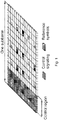
- FIGURE 1 illustrates an example downlink radio subframe.
- the horizontal axis represents time and the other axis represents frequency.
- Each resource element corresponds to one OFDM subcarrier during one OFDM symbol interval.
- LTE downlink transmissions may be organized into radio frames.
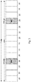
- FIGURE 2 illustrates an example radio frame.
- Tsubframe 1 ms.
- one subframe consists of 14 OFDM symbols.
- the duration of each symbol is approximately 71.4 ⁇ s.
- PRBs Physical resource blocks
- a resource block corresponds to one slot (0.5 ms) in the time domain and 12 contiguous subcarriers in the frequency domain.
- a pair of two adjacent resource blocks in time direction (1.0 ms) is known as a resource block pair.
- the time interval may be referred to as transmission time interval (TTI).
- Downlink transmissions are dynamically scheduled (i.e., in each subframe a base station transmits control information about to which terminals data is transmitted and upon which resource blocks the data is transmitted, for the current downlink subframe).
- CFI Control Format Indicator
- PCFICH Physical CFI channel
- the control region also contains physical downlink control channels (PDCCH) and possibly also physical HARQ indication channels (PHICH) carrying ACK/NACK for the uplink transmission.
- PDCCH physical downlink control channels
- PHICH physical HARQ indication channels
- the downlink subframe also contains common reference symbols (CRS), which are known to the receiver and used for coherent demodulation of, for example, control information.
- CRS common reference symbols
- a Rel-8 TTI one such portion of the downlink transmission is referred to as one TTI.
- Packet data latency is one of the performance metrics that vendors, operators and also end-users (via speed test applications) regularly measure. Latency measurements are done in all phases of a radio access network system lifetime, such as when verifying a new software release or system component, when deploying a system, and when the system is in commercial operation.
- LTE Shorter latency than previous generations of 3GPP RATs is one performance metric that guided the design of LTE.
- LTE is recognized by end-users to provide faster access to internet and lower data latencies than previous generations of mobile radio technologies.
- Packet data latency is important not only for the perceived responsiveness of the system, it is also a parameter that indirectly influences the throughput of the system.
- HTTP/TCP is the dominating application and transport layer protocol suite used on the internet today. According to HTTP Archive (see httparchive.org under trends) the typical size of HTTP based transactions over the internet are in the range of a few 10s of Kbyte up to 1 Mbyte. In this size range, the TCP slow start period is a significant part of the total transport period of the packet stream. During TCP slow start the performance is latency limited. Hence, improved latency can rather easily be showed to improve the average throughput, for this type of TCP based data transactions.
- Radio resource efficiency could be positively impacted by latency reductions.
- Lower packet data latency could increase the number of transmissions possible within a certain delay bound; hence higher Block Error Rate (BLER) targets could be used for the data transmissions freeing up radio resources potentially improving the capacity of the system.
- BLER Block Error Rate
- a TTI corresponds to one subframe (SF) of length 1 millisecond.
- SF subframe
- One such 1 ms TTI is constructed using 14 OFDM or SC-FDMA symbols in the case of normal cyclic prefix and 12 OFDM or SC-FDMA symbols in the case of extended cyclic prefix.
- LTE release 13 may specify transmissions with TTIs that are much shorter than the LTE release 8 TTI.
- the shorter TTIs may have any duration in time and comprise resources on a number of OFDM or SC-FDMA symbols within a 1 ms SF.
- the duration of the short TTI may be 0.5 ms (i.e., seven OFDM or SC-FDMA symbols for the case with normal cyclic prefix).
- the duration of the short TTI may be 2 symbols.
- the TTI length consists of 14 OFDM symbols.
- the TTI length can be reduced to 2-OFDM symbols, 4-OFDM symbols or 7-OFDM symbols. These are denoted as: 2-OS sTTI, 4-OS sTTI, 7-OS sTTI, respectively.
- OFDM symbol herein can also be SC-FDMA symbol or any type of symbol.
- the shortened TTI can be used in different values in different direction, such as downlink and uplink.
- a downlink may use 2-OS sTTI
- uplink may use 4-OS sTTI in the same cell.
- Different frame structures such as FS1, FS2 and FS3, may use different length sTTI.
- the time domain structure in FIGURE 2 relates to FS1.
- 2-OS, 4OS and 7 OS TTI are usable for FS1.
- 7-OS sTTI is one of the shortened TTI modes.
- Some example TTI durations are illustrated in FIGURES 3-5 .
- FIGURE 3 illustrates an example of 7-symbol TTI.
- Each TTI includes 7 OFDM symbols 20.
- the illustrated sTTI structure may also be used for uplink.
- Particular networks may use a 4-symbol TTI in downlink.
- FIGURE 4 illustrates an example of 4-symbol TTI.
- Each TTI includes 4 OFDM symbols 20.
- the illustrated sTTI structure may also be used for uplink.
- FIGURE 5 illustrates examples of short TTI for uplink.
- the example in FIGURE 5 shows various TTI lengths.
- the 2-OS sTTI can have one of the two illustrated options.
- a fast uplink grant may include dynamic indication of TTI length and/or dynamic indication of DMRS position.
- shared DMRS is possible between UEs. For some UEs, this also means that the UE will send DMRS for two TTIs when the UE is scheduled across neighboring TTIs.
- Short TTI may impact the ON/OFF time mask for a UE.
- the general ON/OFF time mask defines the observation period between Transmit OFF and ON power and between Transmit ON and OFF power.
- ON/OFF scenarios include: the beginning or end of DTX, measurement gap, contiguous, and non-contiguous transmission.
- the OFF measurement period is defined in a duration of at least one sub-frame excluding any transient periods.
- the ON power is defined as the mean power over one sub-frame excluding any transient period.
- FIGURE 6 illustrates an example ON/OFF time mask.
- FIGURE 6 is reproduced from TS 36.101, v14.1.0, Figure 6.3.4.1-1.
- the horizontal axis represents time and the vertical axis represent transmission power.
- the ON/OFF time mask is designed for 1 ms TTI in Rel-8 legacy LTE systems.
- the duration of ramping of power (up or down) in the mask is shorter compared to the length of sub-frame or slot, but its position has an influence on system performance.
- the position in time of the ramping or transient period includes a few non-limiting possibilities. Some examples are illustrated in FIGURE 7 .
- FIGURE 7 illustrates three example positions in time for the power up and down transient periods.
- Position (a) illustrates ramping outside a timeslot/sub-frame.
- Position (b) illustrates ramping inside a time slot/sub-frame.
- Position (c) illustrates ramping partly inside and partly outside a timeslot/sub-frame.
- US 2015/0031410 A1 discloses a method and device for controlling uplink transmit power of a terminal in a wireless access system that supports carrier aggregation/multiple cells.
- EP 2 405 695 A1 discloses adapting a time mask to a signal transmission characteristic.
- the UE behavior with respect to ON/OFF time mask may be well defined for different TTI patterns.
- the UE behavior with respect to ON/OFF time mask may be well defined when different TTI patterns are used in consecutive TTIs and the UE may be allocated resources in these consecutive TTIs.
- the UE behavior with respect to ON/OFF time mask may be well defined when different TTI patterns are used in consecutive TTIs and the UE may be allocated overlapping resources in these consecutive TTIs (such as 4-OS TTI arrangements, as shown in FIGURE 4 ).
- Certain embodiments may have none, some, or all of the recited advantages.
- packet data latency is important not only for the perceived responsiveness of the system, it is also a parameter that indirectly influences the throughput of the system. Latency reductions may improve radio resource efficiency.
- One aspect of packet latency reduction is reduction of transport time of data and control signaling by modifying the transmission time interval (TTI) length.
- TTI transmission time interval
- SF subframe
- Newer LTE releases may specify transmissions with TTIs that are shorter than 1 millisecond.
- the duration of the short TTI may be 0.5 ms (i.e., seven orthogonal frequency division multiplexing (OFDM) or single carrier-frequency-division multiplexing (SC-FDMA) symbols for the case with normal cyclic prefix).
- the duration of the short TTI may be 2 symbols or 4 symbols.
- the ON/OFF time mask is defined for a 1 ms TTI duration.
- the transient period is defined as 20 ⁇ s, which is small compared to 1 ms TTI duration.
- the transient period may become significant compared to the TTI duration.
- the problem may become significant when a user equipment (UE) is allocated in two consecutive TTIs. In that case, the legacy mask may cause a large part of the TTI duration to be lost.
- Particular embodiments may enhance the operation related to the transmission of signals by a UE configured with short TTIs.
- a UE is capable of transmitting wireless signals according to an ON/OFF time mask.
- the ON/OFF time mask specifies a length and position of transient periods for power ramp up and ramp down with respect to an associated TTI.
- the UE is operable to obtain a TTI for operating a wireless signal between the UE and a cell.
- the UE determines a first ON/OFF time mask from a plurality of ON/OFF time masks based on the obtained TTI and transmits the wireless signal in the cell according to the determined ON/OFF time mask.
- a network node is capable of receiving wireless signals from the UE according to a ON/OFF time mask.
- the network node is operable to configure the UE with a TTI for operating a wireless signal between the UE and a cell.
- the network node determines a first ON/OFF time mask from a plurality of ON/OFF time masks based on the TTI, and receives the wireless signal from the UE according to the determined ON/OFF time mask.
- first node and second node may be used to refer to two nodes that are either transmitting or receiving in licensed or unlicensed spectrum (or a shared spectrum where more than one system operates based on some kind of sharing regulations).
- An example of a first node includes a network node, which may be a general term that corresponds to any type of radio network node or any network node, which communicates with a UE and/or with another network node.
- network nodes include NodeB, base station (BS), multi-standard radio (MSR) radio node such as MSR BS, eNodeB, gNodeB.
- MeNB SeNB
- network controller radio network controller (RNC), base station controller (BSC), relay, donor node controlling relay, base transceiver station (BTS), access point (AP), transmission points, transmission nodes, RRU, RRH, nodes in distributed antenna system (DAS), core network node (e.g. MSC, MME, etc.), O&M, OSS, SON, positioning node (e.g., E-SMLC), MDT, etc.
- RNC radio network controller
- BSC base station controller
- BSC base station controller
- BTS base transceiver station
- AP access point
- transmission points transmission nodes
- RRU RRU
- RRH nodes in distributed antenna system
- DAS distributed antenna system
- core network node e.g. MSC, MME, etc.
- O&M core network node
- OSS e.g. MSC, MME, etc.
- SON positioning node
- MDT etc.
- a node includes a user equipment
- UE include target device, device to device (D2D) UE, machine type UE or UE capable of machine to machine (M2M) communication, PDA, iPAD, Tablet, mobile terminals, smart phone, laptop embedded equipped (LEE), laptop mounted equipment (LME), USB dongles, etc.
- radio network node or simply “network node (NW node),” which may be any kind of network node such as a base station, radio base station, base transceiver station, base station controller, network controller, evolved Node B (eNB), Node B, relay node, access point, radio access point, Remote Radio Unit (RRU) Remote Radio Head (RRH), etc.
- eNB evolved Node B
- RRU Remote Radio Unit
- RRH Remote Radio Head
- any of the above mentioned nodes could become “the first node” and/or “the second node”.
- a UE may be configured to operate in carrier aggregation (CA), which includes aggregation of two or more carriers in at least one of the downlink and uplink directions.
- CA carrier aggregation
- a UE can have multiple serving cells, wherein the term "serving” herein means that the UE is configured with the corresponding serving cell and may receive from and/or transmit data to the network node on the serving cell (e.g., on PCell or any of the SCells). The data is transmitted or received via physical channels (e.g., PDSCH in downlink, PUSCH in uplink, etc.).
- a component carrier also referred to as a carrier, primary component carrier (PCC), or secondary component carrier (SCC) may be configured at the UE by a network node using higher layer signaling (e.g., by sending a radio resource control (RRC) configuration message to the UE).
- RRC radio resource control
- the configured CC is used by the network node for serving the UE on the serving cell (e.g., on PCell, PSCell, SCell, etc.) of the configured CC.
- the configured CC is also used by the UE for performing one or more radio measurements (e.g., RSRP, RSRQ, etc.) on the cells operating on the CC (e.g., PCell, SCell or PSCell and neighboring cells).
- fallback mode refers herein to a CA configuration which contains fewer CCs than the maximum number of CCs in a CA combination supported by the UE.
- a UE supporting a CA combination with a maximum CA configuration of four downlink CCs and one uplink CC may support the following three fallback modes: three downlink CCs and one uplink CC, two downlink CC and one uplink CC, and one downlink CC and one uplink CC (i.e., single carrier operation).
- the term fallback may also be referred to as lower order CA combination, lower order CA configuration, fallback CA mode, fallback CA configuration mode, or fallback CA combination.
- radio access technology may refer to any RAT, such as UTRA, E-UTRA, narrow band internet of things (NB-IoT), WiFi, Bluetooth, next generation RAT (NR), 4G, 5G, etc.
- RAT may refer to any RAT, such as UTRA, E-UTRA, narrow band internet of things (NB-IoT), WiFi, Bluetooth, next generation RAT (NR), 4G, 5G, etc.
- NB-IoT narrow band internet of things
- NR next generation RAT
- 4G 5G
- Any of the first and the second nodes may be capable of supporting a single or multiple RATs.
- signal used herein may be any physical signal or physical channel.
- Examples of physical signals are reference signal such as PSS, SSS, CRS, PRS, etc.
- the term "physical channel” (e.g., in the context of channel reception) used herein is also referred to as "channel.”
- Examples of physical channels include MIB, PBCH, NPBCH, PDCCH, PDSCH, sPUCCH, sPDSCH. sPUCCH. sPUSCH, MPDCCH, NPDCCH, NPDSCH, E-PDCCH, PUSCH, PUCCH, NPUSCH, etc.
- time resource used herein may correspond to any type of physical resource or radio resource expressed in terms of length of time. Examples of time resources include: symbol, time slot, subframe, radio frame, TTI, interleaving time, etc.
- TTI time period over which a physical channel can be encoded and optionally interleaved for transmission.
- the physical channel is decoded by the receiver over the same time period (T0) over which it was encoded.
- the TTI may also interchangeably called as short TTI (sTTI), transmission time, slot, sub-slot, mini-slot, short subframe (SSF), mini-subframe, etc.
- radio measurement used herein may refer to any measurement based on receiving a radio signal or channel, e.g., power-based measurements such as received signal strength (e.g., RSRP or CSI-RSRP) or quality measurements (e.g., RSRQ, RS-SINR, SINR, Es/Iot, SNR); cell identification; synchronization signals measurements; angle measurements such as angle of arrival (AOA); timing measurements such as Rx-Tx, RTT, RSTD, TOA, TDOA, timing advance; throughput measurements; channel quality measurements such CSI, CQI, PMI, channel measurement (e.g., MIB, SIBs, SI, CGI acquisitions, etc.).
- power-based measurements such as received signal strength (e.g., RSRP or CSI-RSRP) or quality measurements (e.g., RSRQ, RS-SINR, SINR, Es/Iot, SNR); cell identification; synchronization signals measurements; angle measurements such as angle of arrival (AOA); timing
- a measurement may be absolute, relative to a common reference or to another measurement, composite measurement, etc.
- a measurement may be on one link or more than one link (e.g., RSTD, timing advance, RTT, relative RSRP, etc.). Measurements may also be differentiated by purpose and may be performed for one or more purposes, e.g., for one or more of: RRM, MDT, SON, positioning, timing control or timing advance, synchronization. In a non-limiting example, particular embodiments may apply to any measurement such as described above.
- the term "radio measurement” may be used in a broader sense, e.g., receiving a channel (e.g., receiving system information via broadcast or multicast channel).
- UE requirements related to UE measurements may include any type of UE requirements related to UE measurements, such as measurement requirements, RRM requirements, mobility requirements, positioning measurement requirements, etc.
- UE requirements related to UE measurements are measurement time, measurement reporting time or delay, measurement accuracy (e.g., RSRP/RSRQ accuracy), number of cells to be measured over the measurement time, etc.
- measurement time include L1 measurement period, cell identification time or cell search delay, CGI acquisition delay, etc.
- references in the specification to "one embodiment,” “an embodiment,” “an example embodiment,” etc., indicate that the embodiment described may include a particular feature, structure, or characteristic, but every embodiment may not necessarily include the particular feature, structure, or characteristic. Moreover, such phrases are not necessarily referring to the same embodiment. Further, when a particular feature, structure, or characteristic is described in connection with an embodiment, it is submitted that it is within the knowledge of one skilled in the art to implement such feature, structure, or characteristic in connection with other embodiments, whether or not explicitly described.
- FIGS 8-17 of the drawings like numerals being used for like and corresponding parts of the various drawings.
- LTE and NR are used throughout this disclosure as example cellular systems, but the ideas presented herein may apply to other wireless communication systems as well.
- the described embodiments may be implemented in any appropriate type of communication system supporting any suitable communication standards and using any suitable components. As one example, certain embodiments may be implemented in a communication system, such as that illustrated in FIGURE 8 . Although reference may be made to the term "cell,” the described concepts may also apply in other contexts, such as beams used in Fifth Generation (5G) systems, for example.
- 5G Fifth Generation
- FIGURE 8 is a block diagram illustrating an example wireless network, according to a particular embodiment.
- Communication system 1100 comprises a plurality of wireless communication devices 1105 (e.g., UEs, machine type communication (MTC)/machine-to-machine (M2M) UEs) and a plurality of radio access nodes 1110 (e.g., eNodeBs, gNodeBs, or other base stations).
- Communication system 1100 is organized into cells 1115, which are connected to a core network 1120 via corresponding radio access nodes 1110.
- Radio access nodes 1110 are capable of communicating with wireless communication devices 105 along with any additional elements suitable to support communication between wireless communication devices or between a wireless communication device and another communication device (such as a landline telephone).
- wireless communication devices 1105 that are within coverage of radio access node 1110 (e.g., within cell 1115 served by radio access node 1110) communicate with radio access node 1110 by transmitting and receiving wireless signals.
- wireless communication devices 1105 and radio access node 1110 may communicate wireless signals containing voice traffic, data traffic (e.g., broadcast video), and/or control signals.
- a radio access node 1110 communicating voice traffic, data traffic, and/or control signals to wireless communication device 1105 may be referred to as a serving network node 1110 for wireless communication device 1105.
- Wireless signals may include both downlink transmissions (from radio access node 1110 to wireless communication devices 1105) and uplink transmissions (from wireless communication devices 1105 to radio access node 1110).
- wireless communication device 1105 may be referred to by the non-limiting term "UE.”
- a UE may include any type of wireless device capable of communicating with a network node or another UE over radio signals.
- the UE may comprise radio communication device, target device, device to device (D2D) UE, machine type UE or UE capable of machine to machine communication (M2M), a sensor equipped with UE, iPAD, Tablet, mobile terminals, smart phone, laptop embedded equipped (LEE), laptop mounted equipment (LME), USB dongles, Customer Premises Equipment (CPE), etc.
- D2D device to device
- M2M machine to machine communication
- iPAD machine to machine communication
- Tablet mobile terminals
- smart phone laptop embedded equipped (LEE), laptop mounted equipment (LME), USB dongles
- CPE Customer Premises Equipment
- radio access node 1110 may include any type of network node such as a base station, radio base station, base transceiver station, base station controller, network controller, evolved Node B (eNB), gNB, Node B, multi-RAT base station, Multi-cell/multicast Coordination Entity (MCE), relay node, access point, radio access point, Remote Radio Unit (RRU) Remote Radio Head (RRH), a core network node (e.g., MME, SON node, a coordinating node, etc.), or even an external node (e.g., 3rd party node, a node external to the current network), etc.
- a core network node e.g., MME, SON node, a coordinating node, etc.
- an external node e.g., 3rd party node, a node external to the current network
- Communication system 1100 may include various length TTI (e.g., TTI of 1 ms, or short TTI of 2-os, 4-os, 7-os, etc., or any combination). In particular embodiments, communication system 1100 may include different TTI in the downlink and uplink.
- TTI e.g., TTI of 1 ms, or short TTI of 2-os, 4-os, 7-os, etc., or any combination.
- communication system 1100 may include different TTI in the downlink and uplink.
- Wireless communication device 1105 may transmit wireless signals according to an ON/OFF time mask.
- Wireless communication device 1105 may obtain a TTI for operating a wireless signal between wireless communication device 1105 and cell 115, and determine an ON/OFF time mask from a plurality of ON/OFF time masks based on the obtained TTI.
- the ON/OFF time mask specifies a length and position of transient periods for power ramp up and ramp down with respect to an associated TTI.
- Wireless communication device 1105 is operable to transmit the wireless signal in cell 1115 according to the determined ON/OFF time mask. Additional details are described in more depth below.
- Radio access node 1110 may receive wireless signals from wireless communication device 1105 according to a ON/OFF time mask. Radio access node 1110 may configure wireless communication device 1105 with a TTI for operating a wireless signal between wireless communication device 1105 and cell 1115, and determine an ON/OFF time mask from a plurality of ON/OFF time masks based on the TTI. Radio access node 1110 may receive the first wireless signal from wireless communication device 1105 according to the determined first ON/OFF time mask. Additional details are described in more depth below.
- Communication system 1100 may include carrier aggregation.
- wireless communication device 1105 may be served by both two or more radio access nodes 1110 and communicate wireless signals with two or more radio access nodes 1110.
- Each radio access node 1110 may have a single transmitter or multiple transmitters for transmitting wireless signals to wireless communication device 1105.
- radio access node 1110 may comprise a multi-input multi-output (MIMO) system.
- each wireless communication device 1105 may have a single receiver or multiple receivers for receiving signals from radio access nodes 1110.
- each radio access node 1110 may use any suitable radio access technology, such as long term evolution (LTE), LTE-Advanced, NR, UMTS, HSPA, GSM, cdma2000, WiMax, WiFi, and/or other suitable radio access technology.
- Communication system 1100 may include any suitable combination of one or more radio access technologies. For purposes of example, various embodiments may be described within the context of certain radio access technologies. However, the scope of the disclosure is not limited to the examples and other embodiments could use different radio access technologies.
- wireless communication devices 1105 may represent communication devices that include any suitable combination of hardware and/or software, these wireless communication devices may, in certain embodiments, represent devices such as those illustrated in greater detail by FIGURES. 15A and 15B .
- the illustrated radio access node may represent network nodes that include any suitable combination of hardware and/or software, these nodes may, in particular embodiments, represent devices such those illustrated in greater detail by FIGURES 16A, 16B and 17 .
- two cells are mentioned in several places when carrier aggregation is considered.
- the relevant embodiments are applicable to a carrier aggregation combination involving more than two TTIs (or cells or carriers), unless otherwise mentioned.
- the carriers can be inter-band, or intra-band, or mixture of intra- and inter-band carriers.
- the following includes a description of scenarios involving different TTI patterns, methods in a UE of determining ON/OFF time mask when different TTI patterns can be used for one UE in the same cell, and methods in a network node of determining ON/OFF time mask when different TTI patterns can be used for one UE in the same cell.
- One scenario includes a UE configured with at least one serving cell (e.g., PCell), also referred to as single carrier operation.
- the UE is capable of using at least two different TTIs (e.g., TTI of 1 ms and TTI of 2-OS, etc.).
- the UE can be configured with any one of the plurality of TTIs supported by the UE in one time resource in the serving cell.
- the UE may further be capable of supporting operation whereby the TTI is changed over time in the serving cell.
- the UE also be capable of supporting operation using different TTI in uplink and downlink of the serving cell.
- Example of some scenarios are described in Table 1 below. Table 1: Example TTI Patterns No.
- Some scenarios may include a UE configured with at least two serving cells (e.g., PCell and SCell, etc.), also referred to as carrier aggregation or multicarrier operation.
- the UE is capable of using at least two different TTIs (e.g., TTI of 1 ms and TTI of 2-OS, etc.).
- the UE may also support changing the TTI over time in one or more serving cells of the UE.
- the UE may operate using different TTI in uplink and downlink of any one or more of its serving cells.
- An example of some scenarios including multicarrier operation are described in Table 2 below.
- Table 2 Example TTI Patterns for Multicarrier Operation Cases Carrier combinations Example (with two carriers, however not limited to two carriers) Same TTI pattern is used in different UL carriers More than one UL carriers in the aggregation
- a cell Cell1 operating in frequency F1 uses a 1 st TTI pattern in UL, while a cell Cell2 operating in frequency F2 uses the same TTI pattern in UL.
- a UE aggregates Cell1 and Cell2 in one UL CA configuration.
- Different TTI patterns are used in UL different carriers More than one UL carriers in the aggregation
- a cell Cell1 operating in frequency F1 uses a 1 st TTI pattern in UL, while a cell Cell2 operating in frequency F2 uses a 2 nd TTI pattern in UL.
- a UE aggregates Cell1 and Cell2 in one UL CA configuration.
- a method in a user equipment includes the following general steps. Step-1: Obtaining (based on pre-defined rule or receiving from a network node or another UE) or determining a first TTI (TTI1) used for operating a first signal (S1) between a first cell (cell1) on a first carrier (F1) and the UE, and/or obtaining (based on pre-defined rule or receiving from a network node or another UE) or determining a second TTI (TTI2) used for operating a second signal (S2) between a second cell (cell2) on a second carrier (F2) and the UE.
- TTI1 used for operating a first signal (S1) between a first cell (cell1) on a first carrier (F1) and the UE
- TTI2 used for operating a second signal (S2) between a second cell (cell2) on a second carrier (F2) and the UE.
- Step-2 Determining a first type of ON/OFF time mask (mask1) associated with a first TTI1 and/or a second type of ON/OFF time mask (mask2) associated with a second TTI2 based on the determined values of TTI1 and TTI2.
- Step-3 Transmitting signals (S1 and/or S2) to cell1 and/or cell2 respectively based on the determined ON/OFF time masks (mask1 and mask2). An example method is illustrated in FIGURE 9 .
- FIGURE 9 is a flow diagram of an example method in a user equipment, according to some embodiments.
- the method includes transmitting wireless signals according to an ON/OFF time mask.
- one or more steps of method 900 may be performed by wireless communication device 1105 of communication system 1100 described with reference to FIGURE 8 .
- the UE is configured with at least one serving cell in the uplink.
- the serving cell can be cell1 or ce112.
- cell1 and cell2 can be the same in the case of a single serving cell.
- cell1 and cell2 can be different in the case the case of two serving cells.
- cell1 and cell2 may correspond to PCell and SCell respectively, or cell1 and cell2 may correspond to SCell and PCell respectively.
- the UE selects between mask1 and mask2 based on the determined value of TTI1 or TTI2 used for operation in at least one serving cell (e.g., celll). The embodiments, however, are applicable to selecting a mask out of any number of masks based on TTI.
- the method begins at step 912, where the UE obtains a TTI for operating a wireless signal between a UE and a cell.
- wireless communication device 1105 may obtain a TT1 for transmitting and/or receiving wireless signals in cell 1115.
- the UE obtains or determines a first TTI (TTI1) used for operating a first signal between a first cell on a first carrier and the UE.
- the first cell can be a serving cell of the UE (e.g., PCell, PSCell, SCell, etc.).
- the first cell may correspond to an uplink serving cell, in which case the TTI1 corresponds to the TTI of the uplink serving cell.
- the phrase "operating signals" between the first cell and the UE herein include reception of signals by the UE from the first cell and/or transmission of signals by the UE to the first cell.
- Examples of signals received from the first cell at the UE include downlink channels (e.g., PDCCH, PDSCH, sPDCCH, sPDSCH, etc.).
- Examples of signals transmitted by the UE to the first cell include uplink channels (e.g., PUCCH, PUSCH, sPUCCH, sPUSCH, etc.).
- the UE may further obtain or determine a second TTI (TTI2) used for operating a second signal between a second cell on a second carrier and the UE.
- TTI2 a second TTI used for operating a second signal between a second cell on a second carrier and the UE.
- the second cell may include a serving cell of the UE (e.g., PCell, PSCell, etc.).
- the second cell may correspond to an uplink serving cell, in which case TTI2 corresponds to the TTI of the uplink serving cell.
- the UE may determine TTI1 and/or TTI2 based on one or more of the following mechanisms.
- the UE may use pre-defined information (e.g., relation between TTI1 and frequency band of F1; and/or relation between TTI2 and frequency band of F2).
- the UE may use configuration received from the network node (e.g., PCell, SCell, SCell, etc.).
- the UE may determine the TTI pattern used in any time instance in any carrier by receiving control signals in downlink or by receiving a RRC message.
- the UE may use a predefined rule. Examples of rules include the following.
- a UE may apply the same TTI as used in a reference cell. Examples of reference cell includes a PCell or a PSCell.
- a UE may determine the TTI based on a TTI used in the opposite direction of the first cell (and/or the second cell). For example, the UE may assume the same TTI in uplink and downlink of the first cell (and/or the second cell).
- the UE assumes uplink in the first cell uses a TTI that is not shorter than the TTI of the downlink of the first cell (and/or the second cell).
- the UE may use autonomous determination (e.g., the UE uses blind detection by attempting to decode a downlink channel of different pre-define TTIs).
- Carrier aggregation may include different TTIs for some cells of an aggregated group of cells.
- the ON/OFF mask may be the same for some or all of the aggregated cells.
- the UE determines an ON/OFF time mask from a plurality of ON/OFF time masks based on the obtained TTI.
- wireless communication device 1105 may determine an ON/OFF time mask from a plurality of ON/OFF time masked based on the TTI obtained in the previous step.
- the ON/OFF time mask specifies a length and position of transient periods for power ramp up and ramp down with respect to an associated TTI. For particular masks, the duration of the ramp up period may be different than the duration of the ramp down period.
- An ON/OFF time mask may be described with respect to an associated TTI.
- the associated TTI may refer to a TTI type (e.g., a TTI associated with a particular duration, such as a 2-OS TTI, 4-OS TTI, etc.).
- the phrase "associated TTI" may also refer to a TTI in general.
- some embodiments describe an ON/OFF time mask with respect its associated TTI.
- the time mask describes ramp up and/or ramp down transient periods with respect to the start and stop time of a TTI.
- Some embodiments may described an ON/OFF time mask with respect to a particular TTI. For example, an ON/OFF mask be determined in real time based on a current TTI and an adjacent TTI.
- the determination of the masks is done based on TTI duration which depends on at least the TTI used by the UE for at least transmitting signals in its serving cell.
- the time mask may also be referred to as a reference mask or a mask reference (MASKref).
- the UE supports at least two TTIs and the UE can be configured with any of the supported TTIs for operating signals on at least one serving cell.
- Each TTI is associated with a mask.
- the UE selects a mask that is associated with the determined TTI.
- the mask may depend on the TTI as well as the type of signals (Sg) transmitted by the UE in the serving cell both the TTI (TTIu) used in the uplink and the TTI (TTId) used in the downlink of the UE's serving cell.
- types of signals are SRS, DMRS, PUSCH, sPUSCH, PUCCH, sPUCCH, RACH, etc.
- some embodiments determine a first ON/OFF time mask by determining the ON/OFF time mask based on the configured TTI and a signal type of a wireless signal.
- the signal type comprises a signal type of the wireless signal to be received.
- determining the ON/OFF time mask may comprise determining an ON/OFF time mask where the ramp up and ramp down transient periods are positioned in time within the associated TTI.
- determining the ON/OFF time mask may comprise determining an ON/OFF time mask where the ramp up and ramp down transient periods are positioned in time outside of the associated TTI.
- the signal type comprises a signal type of a wireless signal to be received in an adjacent TTI.
- determining the ON/OFF time mask may comprise determining a ON/OFF time mask where the ramp up and ramp down transient periods are positioned in time outside of the associated TTI.
- determining the ON/OFF time mask may comprise determining a ON/OFF time mask where the ramp up and ramp down transient periods are positioned in time within the associated TTI.
- a UE may use a first type of mask (mask1) for a first cell with TTI1, and the UE may use a second type of mask (mask2) for a second cell with TTI2.
- An example of mask1 and mask2 is illustrated in FIGURES 10A and 10B .
- FIGURE 10A is a timing diagram illustrating an ON/OFF time mask with the ramp up and ramp down transient periods positioned in time within the associated TTI, according to some embodiments.
- FIGURE 10B is a timing diagram illustrating an ON/OFF time mask with the ramp up and ramp down transient periods positioned in time outside of the associated TTI, according to some embodiments.
- FIGURE 10A illustrates a first type of mask when ramp up/down is inside the TTI boundary (similar to a legacy mask)
- FIGURE 10B illustrates a second type of mask when ramp up/down is outside the TTI duration.
- the mask may be different than the mask used for 1 ms TTI.
- 1 ms TTI comprises 14 OFDM symbols (with normal cyclic prefix length).
- Table 3 An example of the different masks used for different TTIs is illustrated in Table 3 below. Table 3: An example of masks as function of different TTIs TTI Pattern TTI duration Choice of mask 14-OS 1000 ⁇ s First type of mask according to FIGURE 10A 7-OS 500 ⁇ s Second type of mask according to FIGURE 10B 4-OS 285.71 ⁇ s Second type of mask according to FIGURE 10B 2-OS 142.86 ⁇ s Second type of mask according to FIGURE 10B
- some embodiments determine a first ON/OFF time mask by determining one ON/OFF time mask if a length of the obtained TTI is below a threshold, and determining a different ON/OFF time mask if the length of the obtained TTI is equal to or above the threshold.
- Table 4 A second example of masks as function of different TTIs TTI Pattern TTI duration Choice of mask 14-OS 1000 ⁇ s First type of mask according to FIGURE 10A 7-OS 500 ⁇ s First type of mask according to FIGURE 10A 4-OS 285.71 ⁇ s Second type of mask according to FIGURE 10B 2-OS 142.86 ⁇ s Second type of mask according to FIGURE 10B
- the table, relation mapping, or relating the values of TTI and the corresponding mask parameters can be obtained by the UE based on one or more of the following principles: (a) based on pre-defined rule (e.g., pre-defined requirement in a specification); (b) by receiving it from the network node or from another UE; (c) by autonomous selection by the UE (e.g., based on historical data or statistics); and (d) based on reception performance of uplink signals in a first cell (e.g., if received signal quality is below a threshold, then the UE may adjust its mask as a function of the TTI, that is adjustment may depend in the current TTI).
- pre-defined rule e.g., pre-defined requirement in a specification
- UE by receiving it from the network node or from another UE
- autonomous selection by the UE e.g., based on historical data or statistics
- reception performance of uplink signals in a first cell e.g., if received signal quality is below a threshold
- the UE is scheduled across two consecutive TTIs.
- the UE may choose between any of the masks as shown in FIGURES 11A-11C .
- FIGURES 11A-11C are timing diagrams illustrating ON/OFF time masks used for two or more consecutive TTIs, according to some embodiments.
- FIGURE 11A illustrates a third type of mask when UE is allocated uplink resources in consecutive TTIs. The ramp up and ramp down transient periods for each TTI are positioned in time within each TTI.
- FIGURE 11B illustrates a fourth type of mask when the UE is allocated uplink resources in consecutive TTIs. The ramp up transient periods for each TTI are positioned in time outside of each TTI, and the ramp down transient periods for each TTI are positioned in time within each TTI.
- FIGURE 11C shows a fifth type of mask when the UE is allocated uplink resources in consecutive TTIs.
- the ramp up transient periods for each TTI are positioned in time within each TTI, and the ramp down transient periods for each TTI are positioned in time outside of each TTI.
- An example of the different masks used for different TTIs when a UE is allocated resources in two consecutive TTIs is illustrated in Table 5 below.
- Table 5 An example of masks as function of different TTIs when the UE is allocated resources across two consecutive TTIs TTI Pattern TTI duration Choice of mask 14-OS 1000 ⁇ s Third type of mask according to FIGURE 11(a) 7-OS 500 ⁇ s Fourth or fifth type of mask according to FIGURE 11(b) or (c) 4-OS 285.71 ⁇ s Fourth or fifth type of mask according to FIGURE 11(b) or (c) 2-OS 142.86 ⁇ s Fourth or fifth type of mask according to FIGURE 11(b) or (c)
- Table 6 A second example of masks as function of different TTIs when the UE is allocated resources across two consecutive TTIs TTI Pattern TTI duration Choice of mask 14-OS 1000 ⁇ s Third type of mask according to FIGURE 11(a) 7-OS 500 ⁇ s Third type of mask according to FIGURE 11(a) 4-OS 285.71 ⁇ s Fourth or fifth type of mask according to FIGURE. 11(a) or (c) 2-OS 142.86 ⁇ s Fourth or fifth type of mask according to FIGURE 11(b) or (c)
- a plurality of ON/OFF time masks includes any of the following ON/OFF time masks: a ON/OFF time mask with the ramp up and ramp down transient periods positioned in time within the associated TTI; a ON/OFF time mask with the ramp up and ramp down transient periods positioned in time outside of the associated TTI; a ON/OFF time mask with the ramp up transient period positioned in time within the associated TTI and the ramp down transient period positioned in time outside of the associated TTI; and a ON/OFF time mask with the ramp up transient period positioned in time outside of the associated TTI and the ramp down transient period positioned in time within the associated TTI.
- the associated TTI for each of the plurality of ON/OFF time masks may comprise a plurality of consecutive TTIs.
- the configured first TTI may comprise at least one of an uplink TTI and a downlink TTI.
- the UE decides not to ramp down and ramp up in between two consecutive TTIs, provided that one or more of the following is applicable: (a) uplink resources are allocated to the UE for more than one consecutive TTI; and (b) the resource allocation in frequency domain remains same for consecutive TTIs for the same UE.
- the UE may choose to follow a sixth time mask as illustrated in FIGURES 12A and 12B .
- FIGURES 12A and 12B are timing diagrams illustrating another example of ON/OFF time masks used for consecutive TTIs, according to some embodiments.
- FIGURE 12A illustrates a sixth type of mask with two consecutive TTIs, when the UE does not perform ramp down/up in between two TTIs, while the ramp up and ramp down at the sides of two consecutive TTIs are done within the TTI duration.
- a seventh type of mask, as described with respect to FIGURE 12B is similar to sixth type of mask except that the ramp up and ramp down at both of the two TTIs are done outside TTI boundary.
- FIGURE 13 is timing diagram illustrating an example of ON/OFF time masks used for overlapping consecutive TTIs, according to some embodiments.
- the dotted lines between two consecutive TTIs illustrate that if a large time mask (i.e., a mask that covers more than one TTI) is not used, then the UE will ramp down and ramp up immediately after that in the middle of two TTIs.
- the example masks in FIGURES 11A-13 illustrate two consecutive TTIs.
- the concept of using a large time mask i.e., a time mask that covers more than one TTI, such as the sixth or seventh masks
- a large time mask i.e., a time mask that covers more than one TTI, such as the sixth or seventh masks
- the number of TTIs for which a single time mask is used may be determined by the UE using any of the following methods: (a) UE may determine the number of TTIs for which it has consecutive uplink resource allocation (and same number of RBs are allocated to the UE for all these consecutive TTIs) from the uplink control information (UCI) that it receives in the downlink; (b) the number can be a pre-defined number, such as a maximum of three TTIs, for example; (c) the number can be determined based on a function which includes the TTI duration (e.g., for shorter TTI durations, the maximum allowed consecutive TTIs can be larger compared to larger TTI duration); and (d) the UE may receive the number from the network via network signaling.
- UCI uplink control information
- a choice between the sixth and seventh type of masks may depend on TTI duration.
- TTI duration For example: a possible set is shown below in Table 7.
- Table 7 An example of masks as function of different TTIs when the UE is allocated resources across two consecutive TTIs.
- Table 7 An example of masks as function of different TTIs when the UE is allocated resources across two consecutive TTIs
- the UE may choose any of the masks in FIGURES 11A-13 , depending on whether the power control parameters, resource allocation, etc. are same for consecutive TTIs or not.
- An example combination is shown below: Constraints between two consecutive TTIs Choice of masks Power control and resource allocation related parameters are different for consecutive TTIs Third or fourth or fifth mask as described in FIGURE 11 Power control and resource allocation related parameters are same (or similar) for consecutive TTIs Sixth or seventh mask as described in FIGURE 13
- the UE when two consecutive TTIs overlap each other in time (and a UE is allocated resources in the overlapping consecutive TTIs), then the UE can use a large mask to cover both TTIs. This can happen when shortened TTI patterns, such as 4-OS TTI (as shown in FIGURE 4 ), is used for any carrier, and when a UE is allocated uplink resources in two such consecutive 4-OS TTIs.
- shortened TTI patterns such as 4-OS TTI (as shown in FIGURE 4 )
- the UE can use one mask to cover both TTIs.
- An example mask is illustrated in FIGURE 13 .
- a large mask is used for two overlapping TTIs, while the overlapping symbol is a reference signal (e.g., DMRS) symbol.
- a reference signal e.g., DMRS
- there may be more than one overlapping symbol containing reference signals e.g., 2 DMRS symbols.
- the overlapping symbol(s) may contain any other uplink signal (e.g., SRS, data signal, control channel, etc.).
- solid line masks represent individual TTIs
- dashed line mask represents the large common mask for both TTIs (i.e., one larger mask covers all symbols in the two consecutive TTIs).
- more than 2 TTIs may be included in the large mask if needed.
- An advantage of the larger mask covering both TTIs is that the overlapping symbol (or common symbol(s) such as DMRS) is not affected by the transients of the mask. This in turn ensures that the base station receiving the DMRS can demodulate it correctly and use it for channel estimation.
- the method continues to step 916.
- the UE transmits the wireless signal in the cell according to the determined ON/OFF time mask.
- wireless communications device 1105 transmits a wireless signal in cell 1115 according to the ON/OFF time mask determined in the previous step.
- the UE uses the determined masks (mask1 and/or mask2) associated with the determined value of TTI in the previous step for transmitting signals to the first cell.
- the UE based on the determined masks, ensures that its ON/OFF behavior in the time window follows within the values described by mask1 and/or mask2.
- the UE based on the determined value of mask1 and/or mask2 further ensures that its ON/OFF time window remains within the mask ranges when the TTI over which it transmits the signal is the same as when the mask was used by the UE.
- Some embodiments include a method in a network node.
- the method includes the following steps. Step-1: Configuring a UE with a first TTI (TTI1) used for operating a first signal between a first cell on a first carrier and the UE, and/or with a second TTI (TTI2) used for operating a second signal on a second carrier between a second cell and the UE.
- TTI1 used for operating a first signal between a first cell on a first carrier and the UE
- TTI2 second TTI
- Step-2 Determining based on the determined values of TTI1 and TTI2, a first type of ON/OFF time mask (mask1) associated with a first TTI1 is to be selected or to be used by the UE for transmitting uplink signals and/or a second type of ON/OFF time mask (mask2) associated with a second TTI2 is to be selected or to be used by the UE for transmitting uplink signals.
- Step-3 Receiving the first signal in the first cell from the UE and/or the second signal in the second cell based on the determined ON/OFF time masks.
- Step-4 some embodiments include using the received signal and/or the determined masks for one or more operational tasks. An example method is illustrated in FIGURE 14 .
- FIGURE 14 is a flow diagram of an example method in a network node, according to some embodiments.
- the method includes receiving wireless signals from a UE according to an ON/OFF time mask.
- one or more steps of method 1450 may be performed by radio access node 1110 of communication system 1100 described with reference to FIGURE 8 .
- the method begins at step 1452, where the radio access node configures a UE with a TTI for operating a wireless signal between the UE and a cell.
- radio access node 1110 may configure wireless communication device 1105 with a short TTI for operating a wireless signal between wireless communication device 1105 and cell 1115.
- the network node configures a UE with first TTI (TTI1) used for operating a first signal (S1) between the network node and UE.
- TTI1 may be performed by transmitting a message to UE (e.g., RRC message).
- UE e.g., RRC message
- the network node may determine the value of TTI1 or the need to configure TTI1 (i.e., specific value).
- the network node configures the UE with second TTI (TTI2) used for operating a second signal (S2) between the network node and UE.
- TTI2 may be performed by transmitting a message to UE (e.g., RRC message).
- the network node may determine the value of TTI2 or the need to configure TTI2 (i.e., specific value).
- RTT round trip time
- a UE location with respect to the serving cell e.g., shorter TTI may be used if the UE is closer to the serving cell, i.e., closer to the
- the radio access node determines an ON/OFF time mask from a plurality of ON/OFF time masks based on the TTI. For example, radio access node 1110 may determine an ON/OFF time mask based on the TTI determined in the previous step.
- the network node determines the usable masks (mask1 and/or mask2) based on the configured value of TTI1 and/or TTI2.
- the parameter mask1 and/or mask2 are used by the UE for transmitting uplink signals in cell1 and/or cell2.
- the network node may determine the value of mask1 and/or mask2 based on a relation or mapping between TTIs and the ON/OFF time masks.
- the mapping may contain two TTIs and the corresponding two types of the masks windows for estimating the corresponding ON/OFF time behavior.
- the network node may determine the type of masks using the same principles as described above in connection with step 914 of method 900 described with respect to FIGURE 9 .
- the radio access node receives the wireless signal from the UE according to the determined ON/OFF time mask.
- radio access node 1110 receives the wireless signal from wireless communication device 1105 according to the ON/OFF time mask from the previous step.
- the network node receives a first signal from the UE in the first cell over the configured TTI1, wherein the UE transmit signal follows the mask (i.e., mask1).
- the network node may receive the seconds signal from the UE in the second cell over the configured TTI2, wherein the UE transmit signal follows the mask (i.e., mask2).
- the network node may adapt its receiver configuration base on the determined types of masks (i.e., mask1 and/or mask2).
- the radio access node may use the received wireless signal or determined ON/OFF time mask for one or more operational tasks.
- radio access node 1110 may perform any of the following operational tasks: (a) performing radio measurements in the network node; (b) adapting TTI of the UE in downlink and/or in uplink in the first cell and/or the second cell; (c) adapting TTI of the UE in the first cell and/or the second cell in different time resources; (d) power control operation of the UE in the first cell and/or the second cell; (e) scheduling of data or signal in the uplink and/or in the downlink of the first cell and/or the second cell; (f) adaptation of the receiver configuration of the base station receiving signals from the UE in the first cell and/or the second cell.
- FIGURE 15A is a block diagram illustrating an example embodiment of a wireless communication device.
- a wireless communication device 1200A comprises a processor 1205 (e.g., Central Processing Units (CPUs), Application Specific Integrated Circuits (ASICs), Field Programmable Gate Arrays (FPGAs), and/or the like), a memory 1210, a transceiver 1215, and an antenna 1220.
- processors 1205 e.g., Central Processing Units (CPUs), Application Specific Integrated Circuits (ASICs), Field Programmable Gate Arrays (FPGAs), and/or the like
- a memory 1210 e.g., Random Access (RAMs), Random Access Memory Sticks, and/or the like
- a transceiver 1215 e.g., a transceiver
- an antenna 1220 e.g., a transceiver, and/or the like
- FIGURE 15B is a block diagram illustrating example components of a wireless communication device.
- a wireless communication device 1200B comprises at least one module 1225 configured to perform one or more corresponding functions. Examples of such functions include various method steps or combinations of method steps as described herein with reference to wireless communication device(s).
- a module may comprise any suitable combination of software and/or hardware configured to perform the corresponding function. For instance, in some embodiments a module comprises software configured to perform a corresponding function when executed on an associated platform, such as that illustrated in FIG. 15A . Some embodiments include obtaining module 1250, determining module 1252, and transmitting module 1254.
- Obtaining module 1250 may perform the obtaining functions of wireless communication device 1200A. For example, obtaining module 1250 may perform the obtaining functions of step 912 in FIGURE 9 . In certain embodiments, obtaining module 1250 may include or be included in processor 1205. In particular embodiments, obtaining module 1250 may communicate with determining module 1252, and transmitting module 1254.
- Determining module 1252 may perform the determining functions of wireless communication device 1200A. For example, determining module 1252 may perform the determining functions of step 914 in FIGURE 9 . In certain embodiments, determining module 1252 may include or be included in processor 1205. In particular embodiments, determining module 1252 may communicate with obtaining module 1250 and transmitting module 1254.
- Transmitting module 1254 may perform the transmitting functions of wireless communication device 1200A. For example, transmitting module 1254 may perform the transmitting functions of step 916 in FIGURE 9 . In certain embodiments, transmitting module 1254 may include or be included in processor 1205. In particular embodiments, transmitting module 1254 may communicate with obtaining module 1250 and determining module 1252.
- FIGURE 16A is a block diagram illustrating an example embodiment of a radio access node.
- Radio access node 1300A comprises a control system 1320 that comprises a node processor 1305 (e.g., Central Processing Units (CPUs), Application Specific Integrated Circuits (ASICs), Field Programmable Gate Arrays (FPGAs), and/or the like), memory 1310, and a network interface 1315.
- radio access node 1300A comprises at least one radio unit 1325 comprising at least one transmitter 1335 and at least one receiver 128 coupled to at least one antenna 1330.
- radio unit 1325 is external to control system 1320 and connected to control system 1320 via, e.g., a wired connection (e.g., an optical cable).
- radio unit 1325 and potentially the antenna 1330 are integrated together with control system 1320.
- Node processor 1305 operates to provide at least one function 1345 of radio access node 1300A as described herein.
- the function(s) are implemented in software that is stored, e.g., in the memory 1310 and executed by node processor 1305.
- radio access node 1300 may comprise additional components to provide additional functionality, such as the functionality described herein and/or related supporting functionality.
- FIGURE 16B is a block diagram illustrating example components of a radio access node.
- Radio access node 1300B comprises at least one module 1350 configured to perform one or more corresponding functions. Examples of such functions include various method steps or combinations of method steps as described herein with reference to radio access node(s).
- a module may comprise any suitable combination of software and/or hardware configured to perform the corresponding function. For instance, in some embodiments a module comprises software configured to perform a corresponding function when executed on an associated platform, such as that illustrated in FIGURE 16A . Some embodiments include configuring module 1350, determining module 1352, and receiving module 1354.
- Configuring module 1350 may perform the configuring functions of radio access node 1300A. For example, configuring module 1350 may perform the obtaining functions of step 1452 in FIGURE 14 . In certain embodiments, configuring module 1350 may include or be included in processor 1305. In particular embodiments, configuring module 1350 may communicate with determining module 1352 and receiving module 1354.
- Determining module 1352 may perform the determining functions of radio access node 1300A. For example, determining module 1352 may perform the determining functions of step 1454 in FIGURE 14 . In certain embodiments, determining module 1352 may include or be included in processor 1305. In particular embodiments, determining module 1352 may communicate with configuring module 1350 and receiving module 1354.
- Receiving module 1354 may perform the receiving functions of radio access node 1300A. For example, receiving module 1354 may perform the receiving functions of step 1456 in FIGURE 14 . In certain embodiments, receiving module 1354 may include or be included in processor 1305. In particular embodiments, receiving module 1354 may communicate with configuring module 1350 and determining module 1352.
- FIGURE 17 is a block diagram illustrating a virtualized example of a radio access node, according to some embodiments.
- the concepts described in relation to FIGURE 17 may be similarly applied to other types of network nodes. Further, other types of network nodes may have similar virtualized architectures.
- the term "virtualized radio access node” refers to an implementation of a radio access node in which at least a portion of the functionality of the radio access node is implemented as a virtual component(s) (e.g., via a virtual machine(s) executing on a physical processing node(s) in a network(s)).
- Radio access node 1400 comprises control system 1320 as described in relation to FIG. 16A .
- Control system 1320 is connected to one or more processing nodes 1420 coupled to or included as part of a network(s) 1425 via network interface 1315.
- Each processing node 1420 comprises one or more processors 1405 (e.g., CPUs, ASICs, FPGAs, and/or the like), memory 1410, and a network interface 1415.
- functions 1345 of radio access node 1300A described herein are implemented at the one or more processing nodes 1420 or distributed across control system 1320 and the one or more processing nodes 420 in any desired manner.
- some or all of the functions 1345 of radio access node 1300A described herein are implemented as virtual components executed by one or more virtual machines implemented in a virtual environment(s) hosted by processing node(s) 1420.
- additional signaling or communication between processing node(s) 1420 and control system 1320 is used in order to carry out at least some of the desired functions 1345.
- control system 1320 may be omitted, in which case the radio unit(s) 1325 communicate directly with the processing node(s) 1420 via an appropriate network interface(s).
- a computer program comprises instructions which, when executed by at least one processor, causes at least one processor to carry out the functionality of a radio access node (e.g., radio access node 1110 or 1300A) or another node (e.g., processing node 1420) implementing one or more of the functions of the radio access node in a virtual environment according to any of the embodiments described herein.
- a radio access node e.g., radio access node 1110 or 1300A
- another node e.g., processing node 1420
Claims (18)
- Verfahren zur Verwendung in einer Benutzereinrichtung, UE, zum Senden von Drahtlossignalen gemäß einer EIN-/AUS-Zeitmaske, wobei das Verfahren umfasst:Erhalten (912) eines ersten Übertragungszeitintervalls, TTI, zum Handhaben eines ersten Drahtlossignals zwischen der UE und einer Zelle;Bestimmen (914) einer ersten EIN-/AUS-Zeitmaske aus einer Mehrzahl von EIN-/AUS-Zeitmasken basierend auf einer Länge des erhaltenen ersten TTI, wobei eine EIN-/AUS-Zeitmaske eine Länge und eine Position von Übergangsperioden zur Erhöhung und Senkung von Leistung in Bezug auf ein assoziiertes TTI spezifiziert; undSenden (916) des ersten Drahtlossignals in der Zelle gemäß der bestimmten ersten EIN-/AUS-Zeitmaske.
- Verfahren nach Anspruch 1, wobei die Mehrzahl von EIN-/AUS-Zeitmasken eine der folgenden EIN-/AUS-Zeitmasken umfasst:eine EIN-/AUS-Zeitmaske, wobei die Übergangsperioden der Erhöhung und der Senkung zeitlich innerhalb des assoziierten TTI positioniert sind;eine EIN-/AUS-Zeitmaske, wobei die Übergangsperioden der Erhöhung und der Senkung zeitlich außerhalb des assoziierten TTI positioniert sind;eine EIN-/AUS-Zeitmaske, wobei die Übergangsperiode der Erhöhung zeitlich innerhalb des assoziierten TTI positioniert ist und die Übergangsperiode der Senkung zeitlich außerhalb des assoziierten TTI positioniert ist; undeine EIN-/AUS-Zeitmaske, wobei die Übergangsperiode der Erhöhung zeitlich außerhalb des assoziierten TTI positioniert ist und die Übergangsperiode der Senkung zeitlich innerhalb des assoziierten TTI positioniert ist.
- Verfahren nach Anspruch 2, wobei das assoziierte TTI für jede der Mehrzahl von EIN-/AUS-Zeitmasken eine Mehrzahl von aufeinanderfolgenden TTIs umfasst.
- Verfahren nach einem der Ansprüche 1 bis 3, wobei das Bestimmen (914) der ersten EIN-/AUS-Zeitmaske ein Bestimmen einer EIN-/AUS-Zeitmaske, falls die Länge des erhaltenen ersten TTI unter einer Schwelle liegt, und Bestimmen einer anderen EIN-/AUS-Zeitmaske umfasst, falls die Länge des erhaltenen ersten TTI gleich wie oder über der Schwelle ist.
- Verfahren nach einem der Ansprüche 1 bis 4, wobei das Bestimmen (914) der ersten EIN-/AUS-Zeitmaske ein Bestimmen der ersten EIN-/AUS-Zeitmaske basierend auf dem erhaltenen ersten TTI und einem Signaltyp des zu sendenden ersten Drahtlossignals oder einem Signaltyp eines Drahtlossignals umfasst, das in einem benachbarten TTI gesendet werden soll, das der UE zugewiesen und benachbart zum erhaltenen ersten TTI ist.
- Verfahren nach Anspruch 5, wobei der Signaltyp einen Signaltyp des zu sendenden ersten Drahtlossignals umfasst, und wobei,wenn der Signaltyp des zu sendenden ersten Drahtlossignals ein Referenzsignal umfasst, das Bestimmen (914) der ersten EIN-/AUS-Zeitmaske ein Bestimmen einer EIN-/AUS-Zeitmaske umfasst, wobei die Übergangsperioden der Erhöhung und der Senkung zeitlich innerhalb des assoziierten TTI positioniert sind; und,wenn der Signaltyp des zu sendenden ersten Drahtlossignals Benutzerdaten umfasst, das Bestimmen (914) der ersten EIN-/AUS-Zeitmaske ein Bestimmen einer EIN-/AUS-Zeitmaske umfasst, wobei die Übergangsperioden der Erhöhung und der Senkung zeitlich außerhalb des assoziierten TTI positioniert sind.
- Verfahren nach Anspruch 5, wobei der Signaltyp einen Signaltyp eines Drahtlossignals umfasst, das im benachbarten TTI gesendet werden soll, und wobei,wenn der Signaltyp des Drahtlossignals, das im benachbarten TTI gesendet werden soll, ein Referenzsignal umfasst, das Bestimmen (914) der ersten EIN-/AUS-Zeitmaske ein Bestimmen einer EIN-/AUS-Zeitmaske umfasst, wobei die Übergangsperioden der Erhöhung und der Senkung zeitlich außerhalb des assoziierten TTI positioniert sind; und,wenn der Signaltyp des Drahtlossignals, das im benachbarten TTI gesendet werden soll, Benutzerdaten umfasst, das Bestimmen (914) der ersten EIN-/AUS-Zeitmaske ein Bestimmen einer EIN-/AUS-Zeitmaske umfasst, wobei die Übergangsperioden der Erhöhung und der Senkung zeitlich innerhalb des assoziierten TTI positioniert sind.
- Verfahren nach einem der Ansprüche 1 bis 7, ferner umfassend:Erhalten (912) eines zweiten TTI zum Handhaben eines zweiten Drahtlossignals zwischen der UE und der Zelle; Bestimmen (914) einer zweiten EIN-/AUS-Zeitmaske aus der Mehrzahl von EIN-/AUS-Zeitmasken basierend auf dem erhaltenen zweiten TTI; undSenden (916) des zweiten Drahtlossignals in der Zelle gemäß der zweiten bestimmten EIN-/AUS-Zeitmaske.
- Benutzereinrichtung, UE, (1105), die zum Senden von Drahtlossignalen gemäß einer EIN-/AUS-Zeitmaske imstande ist, wobei die UE einen Prozessor (1205) umfasst, der zum Durchführen des Verfahrens nach einem der Ansprüche 1 bis 8 ausgelegt ist.
- Verfahren zur Verwendung in einem Netzwerkknoten zum Empfangen von Drahtlossignalen von einer Benutzereinrichtung, UE, gemäß einer EIN-/AUS-Zeitmaske, wobei das Verfahren umfasst:Konfigurieren (1452) der UE mit einem ersten Übertragungszeitintervall, TTI, zum Handhaben eines ersten Drahtlossignals zwischen der UE und einer Zelle;Bestimmen (1454) einer ersten EIN-/AUS-Zeitmaske aus einer Mehrzahl von EIN-/AUS-Zeitmasken basierend auf einer Länge des ersten TTI, wobei eine EIN-/AUS-Zeitmaske eine Länge und eine Position von Übergangsperioden zur Erhöhung und Senkung von Leistung in Bezug auf ein assoziiertes TTI spezifiziert; undEmpfangen (1456) des ersten Drahtlossignals von der UE gemäß der bestimmten ersten EIN-/AUS-Zeitmaske.
- Verfahren nach Anspruch 10, wobei die Mehrzahl von EIN-/AUS-Zeitmasken eine der folgenden EIN-/AUS-Zeitmasken umfasst:eine EIN-/AUS-Zeitmaske, wobei die Übergangsperioden der Erhöhung und der Senkung zeitlich innerhalb des assoziierten TTI positioniert sind;eine EIN-/AUS-Zeitmaske, wobei die Übergangsperioden der Erhöhung und der Senkung zeitlich außerhalb des assoziierten TTI positioniert sind;eine EIN-/AUS-Zeitmaske, wobei die Übergangsperiode der Erhöhung zeitlich innerhalb des assoziierten TTI positioniert ist und die Übergangsperiode der Senkung zeitlich außerhalb des assoziierten TTI positioniert ist; undeine EIN-/AUS-Zeitmaske, wobei die Übergangsperiode der Erhöhung zeitlich außerhalb des assoziierten TTI positioniert ist und die Übergangsperiode der Senkung zeitlich innerhalb des assoziierten TTI positioniert ist.
- Verfahren nach Anspruch 11, wobei das assoziierte TTI für jede der Mehrzahl von EIN-/AUS-Zeitmasken eine Mehrzahl von aufeinanderfolgenden TTIs umfasst.
- Verfahren nach einem der Ansprüche 10 bis 12, wobei das Bestimmen (1454) der ersten EIN-/AUS-Zeitmaske ein Bestimmen einer EIN-/AUS-Zeitmaske, falls die Länge des ersten TTI unter einer Schwelle liegt, und Bestimmen einer anderen EIN-/AUS-Zeitmaske umfasst, falls die Länge des ersten TTI gleich wie oder über der Schwelle ist.
- Verfahren nach einem der Ansprüche 10 bis 13, wobei das Bestimmen (1454) der ersten EIN-/AUS-Zeitmaske ein Bestimmen der ersten EIN-/AUS-Zeitmaske basierend auf dem ersten TTI und einem Signaltyp des zu empfangenden ersten Drahtlossignals oder einem Signaltyp eines Drahtlossignals umfasst, das in einem benachbarten TTI empfangen werden soll, das der UE zugewiesen und benachbart zum ersten TTI ist.
- Verfahren nach Anspruch 14, wobei der Signaltyp einen Signaltyp des zu empfangenden ersten Drahtlossignals umfasst, und wobei,wenn der Signaltyp des zu empfangenden ersten Drahtlossignals ein Referenzsignal umfasst, das Bestimmen der ersten EIN-/AUS-Zeitmaske ein Bestimmen einer EIN-/AUS-Zeitmaske umfasst, wobei die Übergangsperioden der Erhöhung und der Senkung zeitlich innerhalb des assoziierten TTI positioniert sind; und,wenn der Signaltyp des zu empfangenden ersten Drahtlossignals Benutzerdaten umfasst, das Bestimmen der ersten EIN-/AUS-Zeitmaske ein Bestimmen einer EIN-/AUS-Zeitmaske umfasst, wobei die Übergangsperioden der Erhöhung und der Senkung zeitlich außerhalb des assoziierten TTI positioniert sind.
- Verfahren nach Anspruch 14, wobei der Signaltyp einen Signaltyp eines Drahtlossignals umfasst, das im benachbarten TTI empfangen werden soll, und wobei, wenn der Signaltyp des Drahtlossignals, das im benachbarten TTI empfangen werden soll, ein Referenzsignal umfasst, das Bestimmen der ersten EIN-/AUS-Zeitmaske ein Bestimmen einer EIN-/AUS-Zeitmaske umfasst, wobei die Übergangsperioden der Erhöhung und der Senkung zeitlich außerhalb des assoziierten TTI positioniert sind; und,
wenn der Signaltyp des Drahtlossignals, das im benachbarten TTI empfangen werden soll, Benutzerdaten umfasst, das Bestimmen der ersten EIN-/AUS-Zeitmaske ein Bestimmen einer EIN-/AUS-Zeitmaske umfasst, wobei die Übergangsperioden der Erhöhung und der Senkung zeitlich innerhalb des assoziierten TTI positioniert sind. - Verfahren nach einem der Ansprüche 10 bis 16, ferner umfassend:Konfigurieren (1452) der UE mit einem zweiten Übertragungszeitintervall, TTI, zum Handhaben eines zweiten Drahtlossignals zwischen der UE und einer Zelle;Bestimmen (1454) einer zweiten EIN-/AUS-Zeitmaske aus der Mehrzahl von EIN-/AUS-Zeitmasken basierend auf dem zweiten TTI; undEmpfangen (1456) eines zweiten Drahtlossignals von der UE gemäß der bestimmten zweiten EIN-/AUS-Zeitmaske.
- Netzwerkknoten (1110), der zum Empfangen von Drahtlossignalen von einer Benutzereinrichtung, UE, (1105) gemäß einer EIN-/AUS-Zeitmaske imstande ist, wobei der Netzwerkknoten einen Prozessor (1305) umfasst, der zum Durchführen des Verfahrens nach einem der Ansprüche 10 bis 17 ausgelegt ist.
Applications Claiming Priority (3)
| Application Number | Priority Date | Filing Date | Title |
|---|---|---|---|
| US201662417729P | 2016-11-04 | 2016-11-04 | |
| US201662418523P | 2016-11-07 | 2016-11-07 | |
| PCT/IB2017/056890 WO2018083659A1 (en) | 2016-11-04 | 2017-11-03 | On/off time mask for short tti |
Publications (2)
| Publication Number | Publication Date |
|---|---|
| EP3536050A1 EP3536050A1 (de) | 2019-09-11 |
| EP3536050B1 true EP3536050B1 (de) | 2022-07-06 |
Family
ID=60543602
Family Applications (1)
| Application Number | Title | Priority Date | Filing Date |
|---|---|---|---|
| EP17808158.4A Active EP3536050B1 (de) | 2016-11-04 | 2017-11-03 | Ein-/ausschaltzeitmaske für kurze tti |
Country Status (10)
| Country | Link |
|---|---|
| US (1) | US10827427B2 (de) |
| EP (1) | EP3536050B1 (de) |
| JP (1) | JP6738489B2 (de) |
| CN (1) | CN109952790B (de) |
| DK (1) | DK3536050T3 (de) |
| ES (1) | ES2926491T3 (de) |
| MX (1) | MX2019005224A (de) |
| PL (1) | PL3536050T3 (de) |
| PT (1) | PT3536050T (de) |
| WO (1) | WO2018083659A1 (de) |
Families Citing this family (8)
| Publication number | Priority date | Publication date | Assignee | Title |
|---|---|---|---|---|
| EP3507932B1 (de) | 2016-11-04 | 2019-09-18 | Telefonaktiebolaget LM Ericsson (publ) | Flexible zeitmasken für den kanalzugriff mittels "listen before talk" |
| US11553513B2 (en) * | 2017-02-06 | 2023-01-10 | Telefonaktiebolaget Lm Ericsson (Publ) | Methods and apparatuses for determining a placement and duration of a transient period of an on/off time mask for uplink transmission |
| US10862640B2 (en) * | 2017-03-24 | 2020-12-08 | Qualcomm Incorporated | Dynamic transient period configurations for shortened transmission time intervals |
| WO2019013572A1 (en) * | 2017-07-12 | 2019-01-17 | Samsung Electronics Co., Ltd. | METHOD AND APPARATUS FOR TRANSMITTING CONTROL SIGNALS AND DATA BASED ON SHORT TTI IN A WIRELESS CELLULAR COMMUNICATION SYSTEM |
| EP3876628A4 (de) * | 2018-11-01 | 2021-12-08 | Beijing Xiaomi Mobile Software Co., Ltd. | Verfahren und vorrichtung zur informationsübertragung sowie basisstation und endgerät |
| CN111327410B (zh) * | 2018-12-17 | 2021-05-18 | 华为技术有限公司 | 一种用于载波聚合系统的通信方法、终端及网络设备 |
| WO2021028835A1 (en) * | 2019-08-15 | 2021-02-18 | Nokia Technologies Oy | Signal quality verification method |
| EP4068880A4 (de) * | 2019-12-24 | 2022-12-28 | Guangdong Oppo Mobile Telecommunications Corp., Ltd. | Informationsübertragungsverfahren und -gerät, elektronische vorrichtung und speichermedium |
Citations (1)
| Publication number | Priority date | Publication date | Assignee | Title |
|---|---|---|---|---|
| EP2405695A1 (de) * | 2008-06-05 | 2012-01-11 | Telefonaktiebolaget L M Ericsson (PUBL) | Verfahren und Anordnung in einem zellularen Kommunikationssystem |
Family Cites Families (7)
| Publication number | Priority date | Publication date | Assignee | Title |
|---|---|---|---|---|
| TW583855B (en) * | 2002-08-22 | 2004-04-11 | Mediatek Inc | Wireless communication device for transmitting RF signals |
| US7277417B2 (en) * | 2003-04-29 | 2007-10-02 | Broadcom Corporation | Low power protocol for wireless terminal peer-to-peer communications |
| WO2013141647A1 (ko) * | 2012-03-22 | 2013-09-26 | 엘지전자 주식회사 | 무선 접속 시스템에서 상향링크 전송 파워 제어 방법 및 이를 위한 장치 |
| WO2015065113A1 (ko) * | 2013-10-31 | 2015-05-07 | 엘지전자(주) | 무선 통신 시스템에서 단말 간 직접 통신을 위한 수행하기 위한 방법 및 장치 |
| CN106063152A (zh) * | 2014-02-12 | 2016-10-26 | Lg电子株式会社 | 无线通信系统中用于发送和接收信号的方法及其装置 |
| US10172098B2 (en) * | 2014-05-29 | 2019-01-01 | Telefonaktiebolaget L M Ericsson (Publ) | Power control for mitigating device-to-device interference to adjacent networks |
| US9763189B2 (en) * | 2014-11-21 | 2017-09-12 | Qualcomm Incorporated | Low power synchronization in a wireless communication network |
-
2017
- 2017-11-03 EP EP17808158.4A patent/EP3536050B1/de active Active
- 2017-11-03 WO PCT/IB2017/056890 patent/WO2018083659A1/en unknown
- 2017-11-03 US US16/317,164 patent/US10827427B2/en active Active
- 2017-11-03 CN CN201780067635.5A patent/CN109952790B/zh active Active
- 2017-11-03 PT PT178081584T patent/PT3536050T/pt unknown
- 2017-11-03 PL PL17808158.4T patent/PL3536050T3/pl unknown
- 2017-11-03 DK DK17808158.4T patent/DK3536050T3/da active
- 2017-11-03 ES ES17808158T patent/ES2926491T3/es active Active
- 2017-11-03 JP JP2019522725A patent/JP6738489B2/ja active Active
- 2017-11-03 MX MX2019005224A patent/MX2019005224A/es unknown
Patent Citations (1)
| Publication number | Priority date | Publication date | Assignee | Title |
|---|---|---|---|---|
| EP2405695A1 (de) * | 2008-06-05 | 2012-01-11 | Telefonaktiebolaget L M Ericsson (PUBL) | Verfahren und Anordnung in einem zellularen Kommunikationssystem |
Also Published As
| Publication number | Publication date |
|---|---|
| CN109952790B (zh) | 2022-03-18 |
| EP3536050A1 (de) | 2019-09-11 |
| US10827427B2 (en) | 2020-11-03 |
| DK3536050T3 (da) | 2022-08-01 |
| JP6738489B2 (ja) | 2020-08-12 |
| PL3536050T3 (pl) | 2022-11-14 |
| PT3536050T (pt) | 2022-07-29 |
| WO2018083659A1 (en) | 2018-05-11 |
| US20190297572A1 (en) | 2019-09-26 |
| MX2019005224A (es) | 2019-08-05 |
| CN109952790A (zh) | 2019-06-28 |
| ES2926491T3 (es) | 2022-10-26 |
| JP2019537885A (ja) | 2019-12-26 |
Similar Documents
| Publication | Publication Date | Title |
|---|---|---|
| EP3536050B1 (de) | Ein-/ausschaltzeitmaske für kurze tti | |
| EP3539320B1 (de) | Inter-frequenz-messungen von fs3-szellen | |
| EP3456108B1 (de) | Uplink-leistungssteuerung für srs-träger-basierte umschaltung | |
| CN109792358B (zh) | 用于配置测量间隙和探测参考信号切换的系统和方法 | |
| US20230123052A1 (en) | Methods and Apparatuses for Determining a Placement and Duration of a Transient Period of an On/Off Time Mask for Uplink Transmission | |
| KR102218369B1 (ko) | Srs 캐리어 기반 스위칭과 연관된 인터럽션들을 제어하기 위해 랜덤 액세스 구성을 적응시키기 위한 방법들 및 장치들 | |
| KR102371206B1 (ko) | 무선 통신 네트워크에 대한 노드 및 동작 방법 | |
| US20190140864A1 (en) | Device-to-device (d2d) channel measurement techniques | |
| US20200029291A1 (en) | Adaptive Timing Adjustment Delay | |
| EP3417563B1 (de) | Verfahren und vorrichtung zur steuerung der unterbrechungsstufe mit rssi-basierten messungen | |
| US10716078B2 (en) | Wireless device, radio-network node, and methods performed therein for managing signaling in a wireless communication network | |
| EP3520309B1 (de) | Verfahren und vorrichtungen zur anpassung der unterbrechung einer versorgenden zelle auf der grundlage von numerologie | |
| CN110192372B (zh) | 在缩短的tti模式中导出连续传输时间间隔(tti)的配置输出功率 | |
| EP3811550A1 (de) | Device-to-device (d2d)-kanalmesstechniken | |
| EP3535892B1 (de) | Kommunikation mit short-tti | |
| OA20331A (en) | On/Off time mask for short TTI. |
Legal Events
| Date | Code | Title | Description |
|---|---|---|---|
| STAA | Information on the status of an ep patent application or granted ep patent |
Free format text: STATUS: UNKNOWN |
|
| STAA | Information on the status of an ep patent application or granted ep patent |
Free format text: STATUS: THE INTERNATIONAL PUBLICATION HAS BEEN MADE |
|
| PUAI | Public reference made under article 153(3) epc to a published international application that has entered the european phase |
Free format text: ORIGINAL CODE: 0009012 |
|
| STAA | Information on the status of an ep patent application or granted ep patent |
Free format text: STATUS: REQUEST FOR EXAMINATION WAS MADE |
|
| 17P | Request for examination filed |
Effective date: 20190430 |
|
| AK | Designated contracting states |
Kind code of ref document: A1 Designated state(s): AL AT BE BG CH CY CZ DE DK EE ES FI FR GB GR HR HU IE IS IT LI LT LU LV MC MK MT NL NO PL PT RO RS SE SI SK SM TR |
|
| AX | Request for extension of the european patent |
Extension state: BA ME |
|
| DAV | Request for validation of the european patent (deleted) | ||
| DAX | Request for extension of the european patent (deleted) | ||
| STAA | Information on the status of an ep patent application or granted ep patent |
Free format text: STATUS: EXAMINATION IS IN PROGRESS |
|
| 17Q | First examination report despatched |
Effective date: 20210203 |
|
| STAA | Information on the status of an ep patent application or granted ep patent |
Free format text: STATUS: EXAMINATION IS IN PROGRESS |
|
| GRAP | Despatch of communication of intention to grant a patent |
Free format text: ORIGINAL CODE: EPIDOSNIGR1 |
|
| STAA | Information on the status of an ep patent application or granted ep patent |
Free format text: STATUS: GRANT OF PATENT IS INTENDED |
|
| RIC1 | Information provided on ipc code assigned before grant |
Ipc: H04W 52/36 20090101ALI20220330BHEP Ipc: H04W 52/04 20090101AFI20220330BHEP |
|
| INTG | Intention to grant announced |
Effective date: 20220425 |
|
| GRAS | Grant fee paid |
Free format text: ORIGINAL CODE: EPIDOSNIGR3 |
|
| GRAA | (expected) grant |
Free format text: ORIGINAL CODE: 0009210 |
|
| STAA | Information on the status of an ep patent application or granted ep patent |
Free format text: STATUS: THE PATENT HAS BEEN GRANTED |
|
| AK | Designated contracting states |
Kind code of ref document: B1 Designated state(s): AL AT BE BG CH CY CZ DE DK EE ES FI FR GB GR HR HU IE IS IT LI LT LU LV MC MK MT NL NO PL PT RO RS SE SI SK SM TR |
|
| REG | Reference to a national code |
Ref country code: AT Ref legal event code: REF Ref document number: 1503766 Country of ref document: AT Kind code of ref document: T Effective date: 20220715 Ref country code: CH Ref legal event code: EP |
|
| REG | Reference to a national code |
Ref country code: DE Ref legal event code: R096 Ref document number: 602017059308 Country of ref document: DE |
|
| REG | Reference to a national code |
Ref country code: PT Ref legal event code: SC4A Ref document number: 3536050 Country of ref document: PT Date of ref document: 20220729 Kind code of ref document: T Free format text: AVAILABILITY OF NATIONAL TRANSLATION Effective date: 20220722 |
|
| REG | Reference to a national code |
Ref country code: DK Ref legal event code: T3 Effective date: 20220726 |
|
| REG | Reference to a national code |
Ref country code: IE Ref legal event code: FG4D |
|
| REG | Reference to a national code |
Ref country code: NL Ref legal event code: FP |
|
| REG | Reference to a national code |
Ref country code: SE Ref legal event code: TRGR |
|
| REG | Reference to a national code |
Ref country code: LT Ref legal event code: MG9D |
|
| REG | Reference to a national code |
Ref country code: ES Ref legal event code: FG2A Ref document number: 2926491 Country of ref document: ES Kind code of ref document: T3 Effective date: 20221026 Ref country code: GR Ref legal event code: EP Ref document number: 20220401755 Country of ref document: GR Effective date: 20221010 |
|
| PG25 | Lapsed in a contracting state [announced via postgrant information from national office to epo] |
Ref country code: RS Free format text: LAPSE BECAUSE OF FAILURE TO SUBMIT A TRANSLATION OF THE DESCRIPTION OR TO PAY THE FEE WITHIN THE PRESCRIBED TIME-LIMIT Effective date: 20220706 Ref country code: NO Free format text: LAPSE BECAUSE OF FAILURE TO SUBMIT A TRANSLATION OF THE DESCRIPTION OR TO PAY THE FEE WITHIN THE PRESCRIBED TIME-LIMIT Effective date: 20221006 Ref country code: LV Free format text: LAPSE BECAUSE OF FAILURE TO SUBMIT A TRANSLATION OF THE DESCRIPTION OR TO PAY THE FEE WITHIN THE PRESCRIBED TIME-LIMIT Effective date: 20220706 Ref country code: LT Free format text: LAPSE BECAUSE OF FAILURE TO SUBMIT A TRANSLATION OF THE DESCRIPTION OR TO PAY THE FEE WITHIN THE PRESCRIBED TIME-LIMIT Effective date: 20220706 Ref country code: FI Free format text: LAPSE BECAUSE OF FAILURE TO SUBMIT A TRANSLATION OF THE DESCRIPTION OR TO PAY THE FEE WITHIN THE PRESCRIBED TIME-LIMIT Effective date: 20220706 |
|
| PG25 | Lapsed in a contracting state [announced via postgrant information from national office to epo] |
Ref country code: IS Free format text: LAPSE BECAUSE OF FAILURE TO SUBMIT A TRANSLATION OF THE DESCRIPTION OR TO PAY THE FEE WITHIN THE PRESCRIBED TIME-LIMIT Effective date: 20221106 |
|
| REG | Reference to a national code |
Ref country code: DE Ref legal event code: R097 Ref document number: 602017059308 Country of ref document: DE |
|
| PG25 | Lapsed in a contracting state [announced via postgrant information from national office to epo] |
Ref country code: SM Free format text: LAPSE BECAUSE OF FAILURE TO SUBMIT A TRANSLATION OF THE DESCRIPTION OR TO PAY THE FEE WITHIN THE PRESCRIBED TIME-LIMIT Effective date: 20220706 Ref country code: RO Free format text: LAPSE BECAUSE OF FAILURE TO SUBMIT A TRANSLATION OF THE DESCRIPTION OR TO PAY THE FEE WITHIN THE PRESCRIBED TIME-LIMIT Effective date: 20220706 Ref country code: CZ Free format text: LAPSE BECAUSE OF FAILURE TO SUBMIT A TRANSLATION OF THE DESCRIPTION OR TO PAY THE FEE WITHIN THE PRESCRIBED TIME-LIMIT Effective date: 20220706 |
|
| PLBE | No opposition filed within time limit |
Free format text: ORIGINAL CODE: 0009261 |
|
| STAA | Information on the status of an ep patent application or granted ep patent |
Free format text: STATUS: NO OPPOSITION FILED WITHIN TIME LIMIT |
|
| PG25 | Lapsed in a contracting state [announced via postgrant information from national office to epo] |
Ref country code: SK Free format text: LAPSE BECAUSE OF FAILURE TO SUBMIT A TRANSLATION OF THE DESCRIPTION OR TO PAY THE FEE WITHIN THE PRESCRIBED TIME-LIMIT Effective date: 20220706 Ref country code: EE Free format text: LAPSE BECAUSE OF FAILURE TO SUBMIT A TRANSLATION OF THE DESCRIPTION OR TO PAY THE FEE WITHIN THE PRESCRIBED TIME-LIMIT Effective date: 20220706 |
|
| 26N | No opposition filed |
Effective date: 20230411 |
|
| P01 | Opt-out of the competence of the unified patent court (upc) registered |
Effective date: 20230523 |
|
| PG25 | Lapsed in a contracting state [announced via postgrant information from national office to epo] |
Ref country code: MC Free format text: LAPSE BECAUSE OF FAILURE TO SUBMIT A TRANSLATION OF THE DESCRIPTION OR TO PAY THE FEE WITHIN THE PRESCRIBED TIME-LIMIT Effective date: 20220706 Ref country code: AL Free format text: LAPSE BECAUSE OF FAILURE TO SUBMIT A TRANSLATION OF THE DESCRIPTION OR TO PAY THE FEE WITHIN THE PRESCRIBED TIME-LIMIT Effective date: 20220706 |
|
| PG25 | Lapsed in a contracting state [announced via postgrant information from national office to epo] |
Ref country code: SI Free format text: LAPSE BECAUSE OF FAILURE TO SUBMIT A TRANSLATION OF THE DESCRIPTION OR TO PAY THE FEE WITHIN THE PRESCRIBED TIME-LIMIT Effective date: 20220706 Ref country code: LU Free format text: LAPSE BECAUSE OF NON-PAYMENT OF DUE FEES Effective date: 20221103 |
|
| PGFP | Annual fee paid to national office [announced via postgrant information from national office to epo] |
Ref country code: NL Payment date: 20231126 Year of fee payment: 7 |
|
| PGFP | Annual fee paid to national office [announced via postgrant information from national office to epo] |
Ref country code: GR Payment date: 20231129 Year of fee payment: 7 Ref country code: GB Payment date: 20231127 Year of fee payment: 7 |
|
| PGFP | Annual fee paid to national office [announced via postgrant information from national office to epo] |
Ref country code: ES Payment date: 20231201 Year of fee payment: 7 |
|
| PGFP | Annual fee paid to national office [announced via postgrant information from national office to epo] |
Ref country code: TR Payment date: 20231024 Year of fee payment: 7 Ref country code: SE Payment date: 20231127 Year of fee payment: 7 Ref country code: PT Payment date: 20231020 Year of fee payment: 7 Ref country code: IT Payment date: 20231122 Year of fee payment: 7 Ref country code: IE Payment date: 20231127 Year of fee payment: 7 Ref country code: FR Payment date: 20231127 Year of fee payment: 7 Ref country code: DK Payment date: 20231127 Year of fee payment: 7 Ref country code: DE Payment date: 20231129 Year of fee payment: 7 Ref country code: CH Payment date: 20231201 Year of fee payment: 7 Ref country code: AT Payment date: 20231019 Year of fee payment: 7 |
|
| REG | Reference to a national code |
Ref country code: AT Ref legal event code: UEP Ref document number: 1503766 Country of ref document: AT Kind code of ref document: T Effective date: 20220706 |
|
| PGFP | Annual fee paid to national office [announced via postgrant information from national office to epo] |
Ref country code: PL Payment date: 20231024 Year of fee payment: 7 Ref country code: BE Payment date: 20231127 Year of fee payment: 7 |
|
| PG25 | Lapsed in a contracting state [announced via postgrant information from national office to epo] |
Ref country code: HU Free format text: LAPSE BECAUSE OF FAILURE TO SUBMIT A TRANSLATION OF THE DESCRIPTION OR TO PAY THE FEE WITHIN THE PRESCRIBED TIME-LIMIT; INVALID AB INITIO Effective date: 20171103 |
|
| PG25 | Lapsed in a contracting state [announced via postgrant information from national office to epo] |
Ref country code: HR Free format text: LAPSE BECAUSE OF FAILURE TO SUBMIT A TRANSLATION OF THE DESCRIPTION OR TO PAY THE FEE WITHIN THE PRESCRIBED TIME-LIMIT Effective date: 20220706 Ref country code: CY Free format text: LAPSE BECAUSE OF FAILURE TO SUBMIT A TRANSLATION OF THE DESCRIPTION OR TO PAY THE FEE WITHIN THE PRESCRIBED TIME-LIMIT Effective date: 20220706 |