EP3535863B1 - Beam management for various levels of beam correspondence - Google Patents
Beam management for various levels of beam correspondence Download PDFInfo
- Publication number
- EP3535863B1 EP3535863B1 EP17788400.4A EP17788400A EP3535863B1 EP 3535863 B1 EP3535863 B1 EP 3535863B1 EP 17788400 A EP17788400 A EP 17788400A EP 3535863 B1 EP3535863 B1 EP 3535863B1
- Authority
- EP
- European Patent Office
- Prior art keywords
- wireless node
- correspondence
- base station
- determining
- level
- Prior art date
- Legal status (The legal status is an assumption and is not a legal conclusion. Google has not performed a legal analysis and makes no representation as to the accuracy of the status listed.)
- Active
Links
Images


Classifications
-
- H—ELECTRICITY
- H04—ELECTRIC COMMUNICATION TECHNIQUE
- H04B—TRANSMISSION
- H04B7/00—Radio transmission systems, i.e. using radiation field
- H04B7/02—Diversity systems; Multi-antenna system, i.e. transmission or reception using multiple antennas
- H04B7/04—Diversity systems; Multi-antenna system, i.e. transmission or reception using multiple antennas using two or more spaced independent antennas
- H04B7/08—Diversity systems; Multi-antenna system, i.e. transmission or reception using multiple antennas using two or more spaced independent antennas at the receiving station
- H04B7/0837—Diversity systems; Multi-antenna system, i.e. transmission or reception using multiple antennas using two or more spaced independent antennas at the receiving station using pre-detection combining
- H04B7/0842—Weighted combining
- H04B7/086—Weighted combining using weights depending on external parameters, e.g. direction of arrival [DOA], predetermined weights or beamforming
-
- H—ELECTRICITY
- H04—ELECTRIC COMMUNICATION TECHNIQUE
- H04B—TRANSMISSION
- H04B7/00—Radio transmission systems, i.e. using radiation field
- H04B7/02—Diversity systems; Multi-antenna system, i.e. transmission or reception using multiple antennas
- H04B7/04—Diversity systems; Multi-antenna system, i.e. transmission or reception using multiple antennas using two or more spaced independent antennas
- H04B7/06—Diversity systems; Multi-antenna system, i.e. transmission or reception using multiple antennas using two or more spaced independent antennas at the transmitting station
- H04B7/0686—Hybrid systems, i.e. switching and simultaneous transmission
- H04B7/0695—Hybrid systems, i.e. switching and simultaneous transmission using beam selection
- H04B7/06952—Selecting one or more beams from a plurality of beams, e.g. beam training, management or sweeping
- H04B7/06966—Selecting one or more beams from a plurality of beams, e.g. beam training, management or sweeping using beam correspondence; using channel reciprocity, e.g. downlink beam training based on uplink sounding reference signal [SRS]
-
- H—ELECTRICITY
- H01—ELECTRIC ELEMENTS
- H01Q—ANTENNAS, i.e. RADIO AERIALS
- H01Q1/00—Details of, or arrangements associated with, antennas
- H01Q1/12—Supports; Mounting means
- H01Q1/22—Supports; Mounting means by structural association with other equipment or articles
- H01Q1/24—Supports; Mounting means by structural association with other equipment or articles with receiving set
- H01Q1/241—Supports; Mounting means by structural association with other equipment or articles with receiving set used in mobile communications, e.g. GSM
- H01Q1/246—Supports; Mounting means by structural association with other equipment or articles with receiving set used in mobile communications, e.g. GSM specially adapted for base stations
-
- H—ELECTRICITY
- H01—ELECTRIC ELEMENTS
- H01Q—ANTENNAS, i.e. RADIO AERIALS
- H01Q3/00—Arrangements for changing or varying the orientation or the shape of the directional pattern of the waves radiated from an antenna or antenna system
- H01Q3/26—Arrangements for changing or varying the orientation or the shape of the directional pattern of the waves radiated from an antenna or antenna system varying the relative phase or relative amplitude of energisation between two or more active radiating elements; varying the distribution of energy across a radiating aperture
- H01Q3/2605—Array of radiating elements provided with a feedback control over the element weights, e.g. adaptive arrays
-
- H—ELECTRICITY
- H04—ELECTRIC COMMUNICATION TECHNIQUE
- H04B—TRANSMISSION
- H04B7/00—Radio transmission systems, i.e. using radiation field
- H04B7/02—Diversity systems; Multi-antenna system, i.e. transmission or reception using multiple antennas
- H04B7/04—Diversity systems; Multi-antenna system, i.e. transmission or reception using multiple antennas using two or more spaced independent antennas
- H04B7/0408—Diversity systems; Multi-antenna system, i.e. transmission or reception using multiple antennas using two or more spaced independent antennas using two or more beams, i.e. beam diversity
-
- H—ELECTRICITY
- H04—ELECTRIC COMMUNICATION TECHNIQUE
- H04B—TRANSMISSION
- H04B7/00—Radio transmission systems, i.e. using radiation field
- H04B7/02—Diversity systems; Multi-antenna system, i.e. transmission or reception using multiple antennas
- H04B7/04—Diversity systems; Multi-antenna system, i.e. transmission or reception using multiple antennas using two or more spaced independent antennas
- H04B7/06—Diversity systems; Multi-antenna system, i.e. transmission or reception using multiple antennas using two or more spaced independent antennas at the transmitting station
- H04B7/0613—Diversity systems; Multi-antenna system, i.e. transmission or reception using multiple antennas using two or more spaced independent antennas at the transmitting station using simultaneous transmission
- H04B7/0615—Diversity systems; Multi-antenna system, i.e. transmission or reception using multiple antennas using two or more spaced independent antennas at the transmitting station using simultaneous transmission of weighted versions of same signal
- H04B7/0617—Diversity systems; Multi-antenna system, i.e. transmission or reception using multiple antennas using two or more spaced independent antennas at the transmitting station using simultaneous transmission of weighted versions of same signal for beam forming
-
- H—ELECTRICITY
- H04—ELECTRIC COMMUNICATION TECHNIQUE
- H04B—TRANSMISSION
- H04B7/00—Radio transmission systems, i.e. using radiation field
- H04B7/02—Diversity systems; Multi-antenna system, i.e. transmission or reception using multiple antennas
- H04B7/04—Diversity systems; Multi-antenna system, i.e. transmission or reception using multiple antennas using two or more spaced independent antennas
- H04B7/06—Diversity systems; Multi-antenna system, i.e. transmission or reception using multiple antennas using two or more spaced independent antennas at the transmitting station
- H04B7/0686—Hybrid systems, i.e. switching and simultaneous transmission
- H04B7/0695—Hybrid systems, i.e. switching and simultaneous transmission using beam selection
- H04B7/06952—Selecting one or more beams from a plurality of beams, e.g. beam training, management or sweeping
- H04B7/0696—Determining beam pairs
-
- H—ELECTRICITY
- H04—ELECTRIC COMMUNICATION TECHNIQUE
- H04B—TRANSMISSION
- H04B7/00—Radio transmission systems, i.e. using radiation field
- H04B7/02—Diversity systems; Multi-antenna system, i.e. transmission or reception using multiple antennas
- H04B7/04—Diversity systems; Multi-antenna system, i.e. transmission or reception using multiple antennas using two or more spaced independent antennas
- H04B7/08—Diversity systems; Multi-antenna system, i.e. transmission or reception using multiple antennas using two or more spaced independent antennas at the receiving station
- H04B7/0802—Diversity systems; Multi-antenna system, i.e. transmission or reception using multiple antennas using two or more spaced independent antennas at the receiving station using antenna selection
- H04B7/0805—Diversity systems; Multi-antenna system, i.e. transmission or reception using multiple antennas using two or more spaced independent antennas at the receiving station using antenna selection with single receiver and antenna switching
- H04B7/0814—Diversity systems; Multi-antenna system, i.e. transmission or reception using multiple antennas using two or more spaced independent antennas at the receiving station using antenna selection with single receiver and antenna switching based on current reception conditions, e.g. switching to different antenna when signal level is below threshold
-
- H—ELECTRICITY
- H04—ELECTRIC COMMUNICATION TECHNIQUE
- H04B—TRANSMISSION
- H04B7/00—Radio transmission systems, i.e. using radiation field
- H04B7/02—Diversity systems; Multi-antenna system, i.e. transmission or reception using multiple antennas
- H04B7/04—Diversity systems; Multi-antenna system, i.e. transmission or reception using multiple antennas using two or more spaced independent antennas
- H04B7/08—Diversity systems; Multi-antenna system, i.e. transmission or reception using multiple antennas using two or more spaced independent antennas at the receiving station
- H04B7/0868—Hybrid systems, i.e. switching and combining
- H04B7/088—Hybrid systems, i.e. switching and combining using beam selection
-
- H—ELECTRICITY
- H04—ELECTRIC COMMUNICATION TECHNIQUE
- H04L—TRANSMISSION OF DIGITAL INFORMATION, e.g. TELEGRAPHIC COMMUNICATION
- H04L5/00—Arrangements affording multiple use of the transmission path
- H04L5/003—Arrangements for allocating sub-channels of the transmission path
- H04L5/0048—Allocation of pilot signals, i.e. of signals known to the receiver
-
- H—ELECTRICITY
- H04—ELECTRIC COMMUNICATION TECHNIQUE
- H04W—WIRELESS COMMUNICATION NETWORKS
- H04W16/00—Network planning, e.g. coverage or traffic planning tools; Network deployment, e.g. resource partitioning or cells structures
- H04W16/24—Cell structures
- H04W16/28—Cell structures using beam steering
-
- H—ELECTRICITY
- H04—ELECTRIC COMMUNICATION TECHNIQUE
- H04W—WIRELESS COMMUNICATION NETWORKS
- H04W36/00—Hand-off or reselection arrangements
- H04W36/08—Reselecting an access point
- H04W36/085—Reselecting an access point involving beams of access points
-
- H—ELECTRICITY
- H04—ELECTRIC COMMUNICATION TECHNIQUE
- H04W—WIRELESS COMMUNICATION NETWORKS
- H04W48/00—Access restriction; Network selection; Access point selection
- H04W48/08—Access restriction or access information delivery, e.g. discovery data delivery
-
- H—ELECTRICITY
- H04—ELECTRIC COMMUNICATION TECHNIQUE
- H04W—WIRELESS COMMUNICATION NETWORKS
- H04W72/00—Local resource management
- H04W72/04—Wireless resource allocation
- H04W72/044—Wireless resource allocation based on the type of the allocated resource
- H04W72/046—Wireless resource allocation based on the type of the allocated resource the resource being in the space domain, e.g. beams
-
- H—ELECTRICITY
- H04—ELECTRIC COMMUNICATION TECHNIQUE
- H04W—WIRELESS COMMUNICATION NETWORKS
- H04W74/00—Wireless channel access
- H04W74/08—Non-scheduled access, e.g. ALOHA
- H04W74/0833—Random access procedures, e.g. with 4-step access
-
- H—ELECTRICITY
- H04—ELECTRIC COMMUNICATION TECHNIQUE
- H04W—WIRELESS COMMUNICATION NETWORKS
- H04W76/00—Connection management
- H04W76/10—Connection setup
- H04W76/18—Management of setup rejection or failure
-
- H—ELECTRICITY
- H04—ELECTRIC COMMUNICATION TECHNIQUE
- H04W—WIRELESS COMMUNICATION NETWORKS
- H04W76/00—Connection management
- H04W76/20—Manipulation of established connections
- H04W76/28—Discontinuous transmission [DTX]; Discontinuous reception [DRX]
Definitions
- the following relates to wireless communication systems, and more particularly to beam management for various levels of beam correspondence.
- Wireless communication systems are widely deployed to provide various types of communication content such as voice, video, packet data, messaging, broadcast, and so on. These systems may be multiple-access systems capable of supporting communication with multiple users by sharing the available system resources (e.g ., time, frequency, and power). Examples of such multiple-access systems include code-division multiple access (CDMA) systems, time-division multiple access (TDMA) systems, frequency-division multiple access (FDMA) systems, and orthogonal frequency-division multiple access (OFDMA) systems.
- CDMA code-division multiple access
- TDMA time-division multiple access
- FDMA frequency-division multiple access
- OFDMA orthogonal frequency-division multiple access
- a wireless multiple-access communication system may include a number of base stations, each simultaneously supporting communication for multiple communication devices, otherwise known as user equipments (UEs).
- a base station may communicate with UEs on downlink channels (e.g ., for transmissions from a base station to a UE) and uplink channels (e.g ., for transmissions from a UE to a base station).
- Wireless communication systems may operate in millimeter wave (mmW) frequency ranges, e.g., 28 GHz, 40 GHz, 60 GHz, etc.
- Wireless communication at these frequencies may be associated with increased signal attenuation (e.g ., path loss), which may be influenced by various factors, such as temperature, barometric pressure, diffraction, etc.
- signal processing techniques such as beamforming, may be used to coherently combine energy and overcome the path losses at these frequencies. Due to the increased amount of path loss in mmW communication systems, transmissions from the base station and/or the UE may be beamformed.
- Wireless communication between two wireless nodes may use beams or beamformed signals for transmission and/or reception.
- a base station may transmit beamformed signals on downlink (DL) beams associated with the base station.
- a UE may receive a signal on one or more DL beams associated with the UE.
- the DL beam associated with the base station and the DL beam associated with the UE used for DL communication between the base station and the UE constitute a DL beam pair.
- a UE may transmit beamformed signals on uplink (UL) beams associated with the UE.
- UL uplink
- a base station may receive a signal on one or more UL beams associated with the base station.
- the UL beam associated with the UE and the UL beam associated with the base station used for UL communication between the UE and the base station constitute an UL beam pair.
- the DL beam pair and the UL beam pair may be the same (e.g., may represent the same beam pairs). In other instances, differences may exist between a DL beam pair and an UL beam pair.
- XINWEI "Beam Management Views and Designs", 3GPP DRAFT; R1 -1609691 presents agreements relating to beam management and channel reciprocity.
- SONY "Discussion on Beam Training Procedure of NR MIMO", 3GPP DRAFT; R1-1609379 presents an overview of hybrid beamforming.
- Some examples of wireless communication systems support beam management for various levels of beam correspondence in accordance with various aspects of the present disclosure.
- beam correspondence may also be referred to as "beam reciprocity.”
- a downlink (DL) transmission, via one or more beams, from a transmitting wireless node may be used to identify a corresponding DL reception beam for a receiving wireless node.
- the DL transmission beam and DL reception beam may be identified as a beam pair for the wireless nodes.
- the DL beam training information may be used to identify a beam pair for an uplink (UL).
- an UL transmission, via one or more beams, from a transmitting wireless node may be used to identify an UL reception beam for a receiving wireless node.
- the wireless nodes may avoid performing a beam sweep to identify a beam pair (i.e., transmission beam and reception beam).
- the level of beam correspondence may be below a threshold and a wireless node may perform at least a partial beam sweep ( e.g ., of a plurality of beams, a subset of the plurality of beams, etc .) to identify a beam pair (i.e., a transmission/reception beam) for the wireless nodes.
- a method of wireless communication is described.
- the method may include performing a first beam sweep procedure to determine a first beam pair that includes a transmit beam of a first wireless node and a receive beam of a second wireless node; identifying a level of correspondence at one or both of the first wireless node and the second wireless node, the level of correspondence being between a transmit beam and a receive beam of a respective wireless node; and determining, based on the level of correspondence, a range of a second beam sweep procedure to be performed in determining a second beam pair that includes a transmit beam of the second wireless node and a receive beam of the first wireless node.
- the apparatus may include means for performing a first beam sweep procedure to determine a first beam pair that includes a transmit beam of a first wireless node and a receive beam of a second wireless node; means for identifying a level of correspondence at one or both of the first wireless node and the second wireless node, the level of correspondence being between a transmit beam and a receive beam of a respective wireless node; and means for determining, based on the level of correspondence, a range of a second beam sweep procedure to be performed in determining a second beam pair that includes a transmit beam of the second wireless node and a receive beam of the first wireless node.
- the apparatus may include a processor, memory in electronic communication with the processor, and instructions stored in the memory.
- the instructions may be operable to cause the processor to perform a first beam sweep procedure to determine a first beam pair that includes a transmit beam of a first wireless node and a receive beam of a second wireless node; identify a level of correspondence at one or both of the first wireless node and the second wireless node, the level of correspondence being between a transmit beam and a receive beam of a respective wireless node; and determine, based on the level of correspondence, a range of a second beam sweep procedure to be performed in determining a second beam pair that includes a transmit beam of the second wireless node and a receive beam of the first wireless node.
- a non-transitory computer readable medium for wireless communication may include instructions operable to cause a processor to perform a first beam sweep procedure to determine a first beam pair that includes a transmit beam of a first wireless node and a receive beam of a second wireless node; identify a level of correspondence at one or both of the first wireless node and the second wireless node, the level of correspondence being between a transmit beam and a receive beam of a respective wireless node; and determine, based on the level of correspondence, a range of a second beam sweep procedure to be performed in determining a second beam pair that includes a transmit beam of the second wireless node and a receive beam of the first wireless node.
- Some examples of the method, apparatus, and non-transitory computer-readable medium described above for determining the range of the second beam sweep procedure to be performed in determining the second beam pair may further include processes, features, means, or instructions for determining that the range of the second beam sweep procedure is equal to a range of the first beam sweep procedure based at least in part on the level of correspondence being below a lower threshold.
- Some examples of the method, apparatus, and non-transitory computer-readable medium described above for determining the range of the second beam sweep procedure to be performed in determining the second beam pair may further include processes, features, means, or instructions for determining that no second beam sweep is to be performed based at least in part on the level of correspondence being above an upper threshold.
- Some examples of the method, apparatus, and non-transitory computer-readable medium described above for determining the range of the second beam sweep procedure to be performed in determining the second beam pair may further include processes, features, means, or instructions for determining that a partial second beam sweep is to be performed based at least in part on the level of correspondence being above a lower threshold and below an upper threshold.
- Some examples of the method, apparatus, and non-transitory computer-readable medium described above may further include processes, features, means, or instructions for determining the range of the second beam sweep procedure to be performed based on a range of calibration values associated with a transmit path and a receive path of the at least one of the first wireless node or the second wireless node.
- the calibration values indicate at least one of an amplitude and phase error of the transmit path and the receive path of the at least one of the first wireless node or the second wireless node.
- Some examples of the method, apparatus, and non-transitory computer-readable medium described above may further include processes, features, means, or instructions for determining the range of the second beam sweep procedure to be performed based on a range of beams that includes either the transmit beam of the first wireless node or the receive beam of the second wireless node of the first beam pair.
- Some examples of the method, apparatus, and non-transitory computer-readable medium described above may further include processes, features, means, or instructions for determining the range of the second beam sweep procedure based at least in part on a difference of indices between the transmit beam and the receive beam of the first wireless node and the receive beam of the second wireless node of the first beam pair.
- determining that the partial second beam sweep is to be performed is further based on an identification of a group of one or more downlinks or uplinks which share a same partial second beam sweep.
- Some examples of the method, apparatus, and non-transitory computer-readable medium described above may further include processes, features, means, or instructions for identifying the group of one or more links through communications between the first wireless node and the second wireless node.
- the group of one or more links are associated with the first wireless node.
- Some examples of the method, apparatus, and non-transitory computer-readable medium described above may further include processes, features, means, or instructions for resetting the group of one or more links as part of a radio link failure (RLF) or handover procedure.
- RLF radio link failure
- determining that the partial second beam sweep is to be performed is further based on a verification that a timer associated with the use of the level of correspondence has expired.
- determining that the partial second beam sweep is to be performed is further based on whether the second wireless node is participating in an initial access with the first wireless node.
- determining that the partial second beam sweep is to be performed is further based on whether the second wireless node is awaking in connected mode from a discontinuous reception (DRX) cycle whose duration exceeds a threshold.
- DRX discontinuous reception
- determining that the partial second beam sweep is to be performed is further based on whether the second wireless node is in an inactive state.
- the second beam sweep is limited to a beam sweep at only one of the first wireless node or the second wireless node when the level of correspondence at the other of the first wireless node or the second wireless node is above an upper threshold.
- Some examples of the method, apparatus, and non-transitory computer-readable medium described above for determining the level of correspondence at one or both of the first wireless node and the second wireless node may further include processes, features, means, or instructions for receiving one or more signals from which the level of correspondence is determined.
- the first beam sweep procedure is based at least in part on a synchronization signal transmission procedure, a beam reference signal, or a beam refinement reference signal, or a channel state information reference signal (CSI-RS) or a mobility reference signal procedure, or a combination thereof.
- CSI-RS channel state information reference signal
- Some examples of the method, apparatus, and non-transitory computer-readable medium described above may further include processes, features, means, or instructions for selecting a transmission time of a random access channel (RACH) signal based on the level of correspondence.
- RACH random access channel
- Some examples of the method, apparatus, and non-transitory computer-readable medium described above may further include processes, features, means, or instructions for enabling beam coordination between the first wireless node and one or more other wireless nodes when a level of correspondence at either the first wireless node or the second wireless node is less than an upper threshold.
- the beam coordination comprises identification of beams to be reserved as downlink beams and identification of beams to be reserved as uplink beams.
- a downlink (DL) transmission via one or more beams, from a transmitting wireless node (e.g., evolved nodeB (eNB)) may be used to identify a corresponding DL reception beam for a receiving wireless node (e.g., user equipment (UE)).
- a transmitting wireless node e.g., evolved nodeB (eNB)
- eNB evolved nodeB
- the DL transmission beam and DL reception beam may be identified as a DL beam pair for the wireless nodes.
- the DL beam training information e.g ., beam pair
- UL uplink
- an UL transmission, via one or more beams, from a transmitting wireless node may be used to identify an UL reception beam for a receiving wireless node (e.g., eNB).
- a transmitting wireless node e.g., UE
- a receiving wireless node e.g., eNB
- the wireless nodes may avoid performing a beam sweep to identify an UL beam pair ( i.e., transmission beam and reception beam).
- the level of beam correspondence may be below a threshold and a wireless node may perform at least a partial beam sweep (e.g., of a plurality of beams, a subset of the plurality of beams, etc .) to identify a beam pair ( i.e., a transmission/reception beam) for the wireless nodes.
- a partial beam sweep e.g., of a plurality of beams, a subset of the plurality of beams, etc .
- wireless nodes may perform a full beam sweep, i.e., to identify a pair of beams for DL or UL transmission.
- a full beam sweep may include a wireless node transmitting an UL or DL transmission via multiple beams to another wireless node, or sweeping through multiple beams in order to receive a transmission.
- a wireless node may also perform a partial beam sweep for UL or DL transmissions based on information associated with an UL beam or DL beam.
- the wireless node may perform a partial beam sweep based on information provided in the signal of the base beam.
- the information may include a beam ID.
- the wireless node may identify the base beam based on the beam ID. Based on identifying the base beam, the wireless node may perform beam training on a link ( e.g., DL or UL) using the base beam and one or more neighboring beams.
- the wireless nodes may determine a beam pair based on analyzing information associated with the base and the neighboring beam. For example, a UE may receive information via a transmission beam from a base station. The UE may map the transmission beam to a corresponding reception beam associated with the UE.
- the corresponding reception beam may be an inferior choice among other neighboring candidate reception beams of the UE.
- the UE may analyze parameters of neighboring candidate reception beams.
- the neighboring candidate reception beams may also receive the transmission beam.
- Some examples of parameters may include signal-to-noise ratio (SNR), among others.
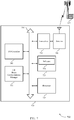
- FIG. 1 illustrates a block diagram of a wireless communication system 100 that supports beam management for various levels of beam correspondence in accordance with various aspects of the present disclosure.
- the wireless communication system 100 includes base stations 105, UEs 115, and a core network 130.
- the core network 130 may provide user authentication, access authorization, tracking, Internet Protocol (IP) connectivity, and other access, routing, or mobility functions.
- IP Internet Protocol
- the base stations 105 interface with the core network 130 through backhaul links 132 (e.g., S1, etc .) and may perform radio configuration and scheduling for communication with the UEs 115, or may operate under the control of a base station controller (not shown).
- the base stations 105 may communicate, either directly or indirectly ( e.g. , through core network 130), with each other over backhaul links 134 ( e.g., X1, etc .), which may be wired or wireless communication links.
- backhaul links 134 e.g., X1, etc .
- the base stations 105 may wirelessly communicate with the UEs 115 via one or more base station antennas. Each of the base stations 105 sites may provide communication coverage for a respective geographic coverage area 110.
- base stations 105 may be referred to as a base transceiver station, a radio base station, an access point, a radio transceiver, a NodeB, eNodeB (eNB), Home NodeB, a Home eNodeB, or some other suitable terminology.
- the geographic coverage area 110 for a base station 105 may be divided into sectors making up only a portion of the coverage area (not shown).
- the wireless communication system 100 may include base stations 105 of different types (e.g., macro and/or small cell base stations). There may be overlapping geographic coverage area 110 for different technologies.
- the wireless communication system 100 is an Long-Term Evolution-Advanced (LTE/LTE-A) network.
- LTE/LTE-A networks the term eNB may be generally used to describe the base stations 105, while the term UE may be generally used to describe the UEs 115.
- the wireless communication system 100 may be a Heterogeneous LTE/LTE-A network in which different types of eNBs provide coverage for various geographical regions. For example, each eNB or base station 105 may provide communication coverage for a macro cell, a small cell, and/or other types of cell.
- cell is a 3rd Generation Partnership Project (3GPP) term that can be used to describe a base station, a carrier or component carrier associated with a base station, or a coverage area ( e.g., sector, etc .) of a carrier or base station, depending on context.
- 3GPP 3rd Generation Partnership Project
- a macro cell generally covers a relatively large geographic area (e.g ., several kilometers in radius) and may allow unrestricted access by UEs with service subscriptions with the network provider.
- a small cell is a lower-powered base station, as compared with a macro cell, that may operate in the same or different ( e.g., licensed, unlicensed, etc .) frequency bands as macro cells.
- Small cells may include pico cells, femto cells, and micro cells according to various examples.
- a pico cell may cover a relatively smaller geographic area and may allow unrestricted access by UEs with service subscriptions with the network provider.
- a femto cell also may cover a relatively small geographic area (e.g., a home) and may provide restricted access by UEs having an association with the femto cell (e.g., UEs in a closed subscriber group (CSG), UEs for users in the home, and the like).
- An eNB for a macro cell may be referred to as a macro eNB.
- An eNB for a small cell may be referred to as a small cell eNB, a pico eNB, a femto eNB or a home eNB.
- An eNB may support one or multiple ( e.g., two, three, four, and the like) cells (e.g., component carriers).
- the wireless communication system 100 may support synchronous or asynchronous operation.
- the base stations may have similar frame timing, and transmissions from different base stations may be approximately aligned in time.
- the base stations may have different frame timing, and transmissions from different base stations may not be aligned in time.
- the techniques described herein may be used for either synchronous or asynchronous operations.
- the communication networks may be packet-based networks that operate according to a layered protocol stack.
- PDCP Packet Data Convergence Protocol
- a Radio Link Control (RLC) layer may perform packet segmentation and reassembly to communicate over logical channels.
- RLC Radio Link Control
- a Medium Access Control (MAC) layer may perform priority handling and multiplexing of logical channels into transport channels.
- the MAC layer may also use Hybrid ARQ (HARQ) to provide retransmission at the MAC layer to improve link efficiency.
- HARQ Hybrid ARQ
- the Radio Resource Control (RRC) protocol layer may provide establishment, configuration, and maintenance of an RRC connection between a UE 115 and the base stations 105 or core network 130 supporting radio bearers for the user plane data.
- RRC Radio Resource Control
- the transport channels may be mapped to Physical channels.
- the UEs 115 are dispersed throughout the wireless communication system 100, and each UE 115 may be stationary or mobile.
- a UE 115 may also include or be referred to by those skilled in the art as a mobile station, a subscriber station, a mobile unit, a subscriber unit, a wireless unit, a remote unit, a mobile device, a wireless device, a wireless communication device, a remote device, a mobile subscriber station, an access terminal, a mobile terminal, a wireless terminal, a remote terminal, a handset, a user agent, a mobile client, a client, or some other suitable terminology.
- a UE 115 may be a cellular phone, a personal digital assistant (PDA), a wireless modem, a wireless communication device, a handheld device, a tablet computer, a laptop computer, a cordless phone, a wireless local loop (WLL) station, or the like.
- PDA personal digital assistant
- a UE may be able to communicate with various types of base stations and network equipment including macro eNBs, small cell eNBs, relay base stations, and the like.
- the communication links 125 shown in wireless communication system 100 may include UL transmissions from a UE 115 to a base station 105, and/or DL transmissions, from a base station 105 to a UE 115.
- the downlink transmissions may also be called forward link transmissions while the uplink transmissions may also be called reverse link transmissions.
- Each communication link 125 may include one or more carriers, where each carrier may be a signal made up of multiple sub-carriers (e.g ., waveform signals of different frequencies) modulated according to the various radio technologies described above. Each modulated signal may be sent on a different sub-carrier and may carry control information
- the communication links 125 may transmit bidirectional communications using frequency division duplexing (FDD) (e.g., using paired spectrum resources) or time division duplexing (TDD) operation (e.g., using unpaired spectrum resources).
- FDD frequency division duplexing
- TDD time division duplexing
- Frame structures for FDD e.g., frame structure type 1
- TDD e.g., frame structure type 2
- base stations 105 and/or UEs 115 may include multiple antennas for employing antenna diversity schemes to improve communication quality and reliability between base stations 105 and UEs 115. Additionally or alternatively, base stations 105 and/or UEs 115 may employ multiple-input, multiple-output (MIMO) techniques that may take advantage of multi-path environments to transmit multiple spatial layers carrying the same or different coded data.
- MIMO multiple-input, multiple-output
- UE 115 may operate based on a discontinuous reception.
- the periodic switching off of a receiver usually to save energy.
- discontinuous reception (DRX) cycles can be configured in the LTE downlink so that the UE does not have to decode the Physical Downlink Control Channel (PDCCH) or receive Physical Downlink Shared Channel (PDSCH) transmissions in certain subframes.
- PDCH Physical Downlink Control Channel
- PDSCH Physical Downlink Shared Channel
- a UE 115 may monitor a communication link 125 continuously for an indication that the UE 115 may receive data.
- a UE 115 may be configured with a DRX cycle.
- a DRX cycle consists of an On Duration when the UE 115 may monitor for control information (e.g ., on PDCCH) and a DRX period when the UE115 may power down radio components.
- control information e.g ., on PDCCH
- a UE 115 may be configured with a short DRX cycle and a long DRX cycle.
- a UE 115 may enter a long DRX cycle if the UE 115 is inactive for one or more short DRX cycles.
- the transition between the short DRX cycle, the long DRX cycle and continuous reception may be controlled by an internal timer or by messaging from a base station 105.
- a UE 115 may receive scheduling messages on PDCCH during the On Duration. While monitoring PDCCH for a scheduling message, the UE 115 may initiate a DRX Inactivity Timer. If a scheduling message is successfully received, the UE 115 may prepare to receive data and the DRX Inactivity Timer may be reset.
- the UE 115 may move into a short DRX cycle and may start a DRX Short Cycle Timer. When the DRX Short Cycle Timer expires, the UE 115 may resume a long DRX cycle.
- base station 105 or UE 115 may communicate one or more messages via a physical broadcast channel (PBCH).
- PBCH physical broadcast channel
- the LTE physical channel which carries the Master Information Block (MIB), consisting of a limited number of the most frequently transmitted parameters essential for initial access to the cell.
- MIB Master Information Block
- the PBCH is designed for early detection by the UE, and cell-wide coverage.
- base station 105 or UE 115 may communicate one or more messages via RRC.
- the RRC protocol handles the Layer 3 control plane signaling by which the E-UTRAN controls the UE behavior.
- the RRC protocol supports the transfer of both common and dedicated Non-Access Stratum information. It covers a number of functional areas including System Information (SI) broadcasting, connection control including handover within LTE, network-controlled inter-Radio Access Technology (radio access technology (RAT)) mobility and measurement configuration and reporting.
- SI System Information
- RAT radio access technology
- base station 105 or UE 115 may communicate one or more messages via a random access channel (RACH).
- RACH random access channel
- the RACH is normally contention-based, which may result in collisions between UEs.
- SIB system information block
- the UE 115 may transmit a RACH preamble to a base station 105. This may be known as RACH message 1.
- the RACH preamble may be randomly selected from a set of 64 predetermined sequences. This may enable the base station 105 to distinguish between multiple UEs 115 trying to access the system simultaneously.
- the base station 105 may respond with a random access response (RAR), or RACH message 2, that provides an UL resource grant, a timing advance and a temporary cell radio network temporary identity (C-RNTI).
- RAR random access response
- RACH message 2 that provides an UL resource grant, a timing advance and a temporary cell radio network temporary identity (C-RNTI).
- C-RNTI temporary cell radio network temporary identity
- the UE 115 may then transmit an RRC connection request, or RACH message 3, along with a temporary mobile subscriber identity (TMSI) (if the UE 115 has previously been connected to the same wireless network) or a random identifier.
- TMSI temporary mobile subscriber identity
- the RRC connection request may also indicate the reason the UE 115 is connecting to the network (e.g. , emergency, signaling, data exchange, etc.).
- the base station 105 may respond to the connection request with a contention resolution message, or RACH message 4, addressed to the UE 115, which may provide a new C-RNTI. If the UE 115 receives a contention resolution message with the correct identification, it may proceed with RRC setup. If the UE 115 does not receive a contention resolution message(e.g., if there is a conflict with another UE 115) it may repeat the RACH process by transmitting a new RACH preamble
- UE 115 may transmit a RACH preamble to a base station 105. This may be known as RACH message 1. This may enable the base station 105 to distinguish between multiple UEs 115 trying to access the system simultaneously.
- the base station 105 may respond with a RAR, or RACH message 2, that provides an UL resource grant, a timing advance and a C-RNTI.
- the UE 115 may then transmit an RRC connection request, or RACH message 3, along with a TMSI (if the UE 115 has previously been connected to the same wireless network) or a random identifier.
- the RRC connection request may also indicate the reason the UE 115 is connecting to the network (e.g., emergency, signaling, data exchange, etc .).
- the base station 105 may respond to the connection request with a contention resolution message, or RACH message 4, addressed to the UE 115, which may provide a new C-RNTI. If the UE 115 receives a contention resolution message with the correct identification, it may proceed with RRC setup. If the UE 115 does not receive a contention resolution message( e.g ., if there is a conflict with another UE 115) it may repeat the RACH process by transmitting a new RACH preamble.
- Wireless communication system 100 may operate in an ultra-high frequency (UHF) frequency region using frequency bands from 700 MHz to 2600 MHz (2.6 GHz), although in some cases wireless local area network (WLAN) networks may use frequencies as high as 4 GHz.
- wireless communication system 100 may also utilize extremely high frequency (EHF) portions of the spectrum (e.g ., from 30 GHz to 300 GHz). This region may also be known as the millimeter band, since the wavelengths range from approximately one millimeter to one centimeter in length.
- EHF antennas may be even smaller and more closely spaced than UHF antennas. In some cases, this may facilitate use of antenna arrays within a UE 115 ( e.g., for directional beamforming).
- EHF transmissions may be subject to even greater atmospheric attenuation and shorter range than UHF transmissions.
- wireless communication system 100 may operate in millimeter wave (mmW) frequency ranges, e.g., 28 GHz, 40 GHz, 60 GHz, etc.
- Wireless communication at these frequencies may be associated with increased signal attenuation (e.g ., path loss), which may be influenced by various factors, such as temperature, barometric pressure, diffraction, etc.
- signal processing techniques such as beamforming (i.e., directional transmission) may be used to coherently combine signal energy and overcome the path loss in specific beam directions.
- a device such as a UE 115, may select a beam direction for communicating with a network by selecting the strongest beam from among a number of signals transmitted by a base station 105.
- the signals may be DL signals transmitted from the base station 105 during discovery.
- the discovery procedure may be cell-specific, e.g. , may be directed in incremental directions around the geographic coverage area 110 of the base station 105.
- the discovery procedure may be used, at least in certain aspects, to identify and select beam(s) to be used for beamformed transmissions between the base station 105 and a UE 115.
- base station antennas may be located within one or more antenna arrays.
- One or more base station antennas or antenna arrays may be collocated at an antenna assembly, such as an antenna tower.
- antennas or antenna arrays associated with a base station 105 may be located in diverse geographic locations.
- a base station 105 may multiple use antennas or antenna arrays to conduct beamforming operations for directional communications with a UE 115.
- Wireless communication system 100 may be or include a multicarrier mmW wireless communication system.
- aspects of wireless communication system 100 may include a UE 115 and a base station 105 configured to beam management for various levels of beam correspondence in accordance with various aspects of the present disclosure.
- the base station 105 and/or UE 115 may perform a first beam sweep procedure to determine a first beam pair that includes a transmit beam of a first wireless node (e.g., UE 115 or base station 105) and a receive beam of a second wireless node (e.g., UE 115 or base station 105).
- UE 115 or base station 105 may identify a level of correspondence at one or both of the first wireless node and the second wireless node, the level of correspondence being between a transmit beam and a receive beam of a respective wireless node. That is, UE 115 may be aware in advance its level of correspondence; for example, based on device (i.e., UE 115) calibration. In some cases, UE 115 or base station 105 may determine, based on the first beam pair, a level of correspondence at one or both of the first wireless node and the second wireless node.
- UE 115 or base station 105 may determine, based on the level of correspondence, a range of a second beam sweep procedure to be performed in determining a second beam pair that includes a transmit beam of the second wireless node and a receive beam of the first wireless node.
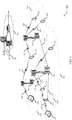
- FIG. 2A and 2B illustrate an example of a wireless communication system 200 that supports beam management for various levels of beam correspondence in accordance with various aspects of the present disclosure.
- FIG. 2A illustrates an example of a wireless communication system 200-a that supports beam management for various levels of beam correspondence in accordance with various aspects of the present disclosure.
- Wireless communication system 200-a may be an example of one or more aspects of wireless communication system 100 of FIG. 1 . Some examples of wireless communication system 200-a may be a mmW wireless communication system.
- Wireless communication system 200-a may include UE 115-a and base station 105-a, which may be one or more aspects of UE 115 and base station 105 as described with reference to FIG. 1 .
- wireless communication system 200-a may determine a level of beam correspondence based on one or more transmissions of signals between base station 105-a and UE 115-a.
- base station 105-a, or UE 115-a, or both may perform beam training based on received signals from the transmitting device (e.g ., base station 105-a or UE 115-a).
- Base station 105-a may be a mmW base station that may transmit a beamformed transmission on an active beam to UE 115-a.
- a transmission from base station 105-a may be a beamformed or directional transmission directed towards UE 115-a.
- base station 105-a may perform a beam sweep by transmitting signals to UE 115-a on DL transmission beams 205-a through 205-d.
- Base station 105-a may transmit DL signals in a beamformed manner and sweep through the angular coverage region for a geographic coverage area 110-a.
- Each DL transmission beams 205-a through 205-d may be transmitted in a beam sweeping operation in different directions so as to cover the coverage area of base station 105-a.
- DL transmission beam 205-a may be transmitted in a first direction
- DL transmission beam 205-b may be transmitted in a second direction
- DL transmission beam 205-c may be transmitted in a third direction
- DL transmission beam 205-d may be transmitted in a fourth direction.
- wireless communication system 200 illustrates four DL transmission beams, i.e., DL transmission beams 205-a through 205-d, it is to be understood that fewer and/or more DL transmission beams may be transmitted.
- the DL transmission beams may additionally be transmitted at variable beam widths, at different elevation angles, etc.
- DL transmission beams 205-a through 205-d may be associated with a beam index, e.g., an indicator identifying the DL transmission beam.
- UE 115-a may, in some examples, identify a DL reception beam based on the beam index received and associated with the DL transmission beam ( e.g., DL transmission beam 205-b).
- base station 105-a may determine an UL reception beam based on one or more received UL signals received from UE 115-a.
- Base station 105-a may, additionally or alternatively, transmit DL transmission beams 205-a through 205-d during different symbol periods of a subframe. For example, base station 105-a may transmit DL transmission beam 205-a during a first symbol period (e.g., symbol 0), DL transmission beam 205-b during a second symbol period ( e.g ., symbol 1), DL transmission beam 205-c during a third symbol period ( e.g ., symbol 2), and DL transmission beam 205-d during a fourth symbol period (e.g. , symbol 3). In some cases, base station 105-a may also transmit DL transmission beams 205-a through 205-d during other symbol periods of a subframe.
- UE 115-a may identify a DL reception beam based on the symbol period of the subframe associated with the received DL transmission beam (e.g., DL transmission beam 205-b). UE 115-a may also transmit a report to base station 105-a indicating to base station the DL reception beam for UE 115-a.
- UE 115-a may determine a range associated with a beam sweep procedure based on a range associated with a beam sweep for base station 105-a.
- the range may include multiple thresholds, for example, different levels of inner thresholds that determine a level of correspondence for a partial beam sweep.
- a range may have a first threshold (e.g., ratios of an amplitude and phase error of a transmit path and a receive path).
- the first threshold may include within it multiple sub-thresholds (e.g., received signal strength, channel/link quality, etc.).
- UE 115-a may determine a range for a beam sweep procedure equal to the beam sweep of base station 105-a based on the level of beam correspondence being below a lower threshold. UE 115-a may determine that no beam sweep is to be performed based on the level of beam correspondence beaning above an upper threshold. Alternatively, UE 115-a may determine to perform a partial beam sweep based on the level of beam correspondence being above the lower threshold and below the upper threshold.
- base station 105-a may perform beam sweeping to determine a location and direction of UE 115-a.
- the beam sweeping operation may improve communication between base station 105-a and UE 115-a when a level of correspondence does not hold between DL or UL channels.
- base station 105-a may receive a response signal from UE 115-a.
- a response signal may include calibration values for calibrating a transmit path and receive path for UE 115-a.
- UE 115-a may determine a level of correspondence for an UL transmission beam or DL reception beam using the calibration values.
- UE 115-a or base station 105-a may, additionally or alternatively, determine a range for a beam sweep procedure based on a range of calibration values associated with a transmit path and a receive path.
- UE 115-a may determine the range of the beam sweep procedure to be performed based on a range of beams straddling the transmit beam of the base station 105-a and the receive beam of UE 115-a.
- base station 105-a may determine the range of the beam sweep procedure to be performed based on a range of beams straddling the transmit beam of the UE 115-a and the receive beam of base station 105-a.
- base station 105-a or UE 115-a may determine the range of a second beam sweep procedure based on a difference of indices between the transmit beam and the receive beam of base station 105-a or UE 115-a and the receive beam of base station 105-a or UE 115-a for DL and UL.
- the range of calibration values includes at least one of a range of amplitude error of antenna weights, a range of phase error of the antenna weights, or combinations thereof. In some cases, the range of calibration values includes at least a difference between amplitude error of antenna weights associated with the transmit path and the receive path, a difference between phase error of antenna weights associated with the transmit path and the receive path, or combinations thereof.
- Base station 105-a or UE 115-a may determine an uncertainty for beam mapping based on difference between amplitude error of antenna weights and phase error of antenna weights.
- base station 105-a and UE 115-a may include one or more antenna arrays.
- An antenna array may include one or more antenna elements.
- a DL transmission beam may be transmitted from base station 105-a to UE 115-a. Subsequent to the DL transmission, one or more antenna elements of UE 115-a may receive the DL transmission beam.
- an UL transmission beam may be transmitted from UE 115-a to base station 105-a. As a result, one or me antenna elements of base station 105-a may receive the UL transmission beam.
- base station 105-a and/or UE 115-a may determine a level of beam non-correspondence.
- Determining a level of beam non-correspondence may include base station 105-a and UE 115-a computing calibration values.
- computing calibration values may include calculating amplitude and phase error of transmit and receive signals (e.g ., beams).
- base station 105-a or UE 115-a may compute an array weight vector associated with an incoming signal ( e.g ., transmission beam). For example, assume that an antenna array has N elements.
- a transmit path associated with DL and UL signals in wireless communication system 200 may be subject to amplitude and phase error.
- ⁇ 0, tx is the amplitude error that may be a value within a range ( e.g., 0.9 to 1.1)
- k is the wavenumber of the incoming signal ( i.e., transmission beam)
- d is the spacing between the antenna elements of an antenna array
- ⁇ is the angle of
- ⁇ 0 ,tx is the phase error term.
- each antenna element of an antenna array may have different phase error terms.
- a first phase error term may be related to a first antenna element and have a first value while a second phase error term may relate to a second antenna element and includes a second value different from the first value.
- a receive path of DL and UL signals in wireless communication system 200-a may be subject to amplitude and phase error.
- ⁇ 0, rx is the amplitude error may be a value within a range of values
- k is the wavenumber of the incoming signal
- d is the spacing between the antenna elements of the antenna array
- ⁇ is the angle of the incoming signal.
- ⁇ 0 ,rx is the phase error term at antenna elements 0, 1 ... N-1
- Phase error may, in some cases, shift a direction of one or more beams associated with base station 105-a or UE 115-a.
- the phase error in some examples, may be assumed to be uniformly distributed in a range.
- the range may be identified by a number of bits in a phase quantizer.
- a phase error may be range uniformly between - ⁇ / 2 B to + ⁇ /2 B .
- the ⁇ term denotes that angular shift for a corresponding beam ( e.g ., transmission beam or reception beam).
- base station 105-a or UE 115-a may align a beam toward an angle of arrival at one or more of the antenna elements 0, 1 ... N-1.
- base station 105-a or UE 115-a may align a beam by shifting the beam to the left or right relative to the angle of arrival axis.
- base station 105-a or UE 115-a may be restricted from shifting a beam towards an angle of arrival, even when the angular shift term ⁇ is equal to zero, based on presence of random phase error. As a result, there may be an absence of a level of beam correspondence for base station 105-a or UE 115-a.
- Phase error may additionally affect neighboring beams associated with a base beam angled towards the angle of arrival.
- a neighboring beam e.g ., beam 205-a or beam 205-c
- Some examples of wireless communication system 200 may use a two-bit phase quantizer to mitigate an array gain of neighboring beams exceeding an array gain of the base beam, i.e., the beam intended to point to the angle of arrival.
- the phase error ranges between -45 degrees to +45 degrees
- UE 115-a or base station 105-a may identify that a level of beam correspondence exists and beam training on the DL can be used to identify beam pairs in the UL.
- some examples of wireless communication system 200 may use a one-bit phase quantizer to mitigate an array gain of neighboring beams exceeding an array gain of the base beam, i.e., the beam intended to point to the angle of arrival.
- the phase error may be distributed randomly and uniformly between a range of -90 degrees to +90 degrees.
- a gain of an antenna array element associated with a neighboring beam of base station 105-a may less likely exceed the gain of the antenna array element of the base beam (e.g. , base beam 205-b) that may point towards a direction of UE 115-a.
- base station 105-a or UE 115-a may perform a partial beam sweep in the UL based on determining the range of beam sweep based on information obtained from DL.
- Base station 105-a or UE 115-a may transmit range of amplitude and phase error to each other, for example, in a header of a data packet.
- base station 105-a may use a same beam to transmit a DL beam training signal and to receive an UL beam training signal from UE 115-a.
- Base station 105-a may compare the DL received signal strength of a DL transmit beam and the UL received signal strength of an UL receive beam to determine an existence or absence of beam correspondence.
- each antenna element of antenna array may include different phase error terms. Additionally, wireless communication system 200 may determine a level of beam correspondence based on a ratio of the amplitude and phase error associated with a transmit path and a receive path. In some examples, a level of beam correspondence may exists based on the ratios of the amplitude and phase error of the transmit path and the receive path being within a threshold range of each other.
- UE 115-a or base station 105-a may determine that a partial beam sweep is to be performed based on a verification that a timer associated with the use of the level of correspondence has expired.
- a received response signal from UE 115-a may be an indication to base station 105-a of a DL quality associated with the transmission of the DL beam used to transmit the DL signal to UE 115-a.
- the indication may be a DL quality associated with a DL beam pair.
- a DL beam pair may include a DL transmit beam (e.g., DL transmission beam 205-b) associated with base station 105-a and DL reception beam associated with UE 115-a.
- UE 115-a may determine a reference signal received power (RSRP) for a DL transmission associated with a DL transmission beam.
- RSRP reference signal received power
- base station 105-a may receive an indication of the RSRP association with the DL transmission from UE 115-a.
- Base station 105-a in some examples may determine an UL quality associated with an UL transmission beam from UE 115-a.
- the UL quality may be based on a SNR of an UL beam pair.
- an UL beam pair may include an UL transmit beam associated with UE 115-a and an UL reception beam associated with base station 105-a.
- Base station 105-a or UE 115-a may determine the SNR based on the UL transmit beam or UL receive beam.
- base station 105-a or UE 115-a may determine a level of correspondence using the DL quality.
- base station 105-a or UE 115-a may determine the level of correspondence using the UL quality.
- base station 105-a may transmit at a higher power level compared to UE 115-a.
- a duration of an UL beam sweep may have a longer duration compared to a DL beam sweep.
- the duration of an UL beam sweep may be determined based on a link budget, i.e., a difference between transmit power between DL and UL.
- Base station 105-a and UE 115-a may transmit messages using one or more physical channels or control channels.
- base station 105-a or UE 115-a may transmit an indication identifying a level of correspondence to each other via a PBCH.
- base station 105-a or UE 115-a may transmit an indication identifying a level of correspondence to each other via a RACH message.
- base station 105-a and UE 115-a may transmit the indication via msgl-msg4 of RACH.
- base station 105-a or UE 115-a may transmit an indication identifying a level of correspondence to each other via physical uplink control channel (PUCCH).
- PUCCH physical uplink control channel
- Base station 105-a or UE 115-a in some cases may transmit an indication identifying a level of correspondence to each other via a RRC message.
- base station 105-a or UE 115-a may select a frequency region and/or a waveform configuration for transmitting random access signal (e.g ., RACH message or msgl-msg4) based on an index of an identified DL signal of a DL transmission beam 205-a, 205-b, 205-c, or 205-d.
- base station 105-a may identify an UL transmission beam by receiving the random access signal in a sweeping manner.
- Base station 105-a may also identify the UE 115-a selected DL reception beam from the frequency resource and/or RACH waveform used (e.g., the used frequency region and/or waveform configuration) that includes the RACH message (e.g ., msgl) of the random access signal.
- RACH waveform used e.g., the used frequency region and/or waveform configuration
- RACH message e.g ., msgl
- UE 115-a may receive one or more DL signals on one or more DL transmission beams 205-a through 205-d.
- the UE 115-a may identify a DL reception beam that satisfies a threshold, e.g ., received signal strength threshold, channel/link quality threshold, etc..
- UE 115-a may identify a candidate DL reception beam based on a DL signal satisfying the threshold.
- UE 115-a may select a corresponding DL reception beam associated with the DL transmission beam.
- UE 115-a may identify a frequency resource and/or RACH waveform to use for transmission of the RACH message based on the selected DL reception beam.
- the frequency resource and/or RACH waveform used for the transmission of the RACH message may correspond to the symbol of the identified DL transmission beam.
- base station 105-a may identify a DL reception beam of UE 115-a from the used frequency region and/or RACH waveform that contains the message-1 of random access signal.
- Base station 105-a may determine an UL reception beam by measuring a quality of the received signal at different uplink receiver beams ( e.g. , DL beams 205-a through 205-d).
- the signal quality may denote one or more combinations of RSRP, or a received signal strength indication (RSSI), or a reference signal received quality (RSRQ), SNR, signal-to-interference-plus-noise ratio (SINR), etc.
- UE 115-a may select a DL reception beam and selects the frequency region of RACH and/or RACH waveform based on the index of the DL transmission beam.
- UE 115-a may select a DL reception beam that satisfies a transmit power condition.
- FIG. 2B illustrates an example of a wireless communication system 200-b that supports a level of beam correspondence, in accordance with aspects of the present disclosure.
- Wireless communication system 200-a may be an example of one or more aspects of wireless communication system 100 of FIG. 1 .
- Some examples of wireless communication system 200-b may be a mmW wireless communication system.
- Wireless communication system 200-b may include UE 115-b and base station 105-b, which may be one or more aspects of UE 115 and base station 105 as described with reference to FIG. 1 .
- UE 115-b of wireless communication system 200-b may determine a level of beam correspondence based on one or more signals transmitted between base station 105-b and UE 115-b.
- UE 115-b may perform beam training based on received signals from base station 105-b.
- beam training may include a full beam sweep, a partial beam sweep, or no beam sweep.
- a full beam sweep may include analyzing beams 210-a through 210-d.
- a partial beam sweep may include analyzing beams 210-b and neighboring beams 210-a and 210-c.
- no beam sweep may occur when a level of beam correspondence exists where UE 115-b may not be required to analyze additional beams (e.g ., beams 210-a or beams 210-c) to determine a DL reception beam or UL transmission beam.
- UE 115-b may receive one or more DL signals from base station 105-b.
- a transmissions from UE 115-b may be a beamformed or directional transmission directed towards base station 105-b.
- beams 210-a through 210-d may be one or more aspects of beams 205-a through 205-d as described with reference to FIG. 2 .
- beams 210-a through 210-d may be one or more aspects of DL reception beams.
- UE 115-b may determine a DL reception beam based on a DL signal received from base station 105-b.
- UE 115-b may determine a level of beam correspondence based on the received DL transmission signal.
- the received DL transmission signal may be associated with an individual DL transmission beam ( e.g., DL transmission beams 205-a through 205-d as described with reference to FIG. 2 ).
- UE 115-b may determine that at least one of beam 210-a, beam 210-b, beam 210-c, or beam 210-d may be a beam pair, i.e., DL reception beam for the DL transmission beam.
- beams 210-a through 210-d may be one or more aspects of an UL transmission beam.
- UE 115-b may transmit an UL signal via one or more UL transmission beams (e.g ., UL transmission beams 210-a through 210-d) to base station 105-b.
- UE 115-b may transmit UL signal in a beamformed manner and sweep through an angular coverage region for a geographic coverage area 110-b.
- Each UL transmission beam 210-a through 210-d may be transmitted in a beam sweeping operation in different directions.
- UL transmission beam 210-a may be transmitted in a first direction
- UL transmission beam 210-b may be transmitted in a second direction
- UL transmission beam 210-c may be transmitted in a third direction
- UL transmission beam 210-d may be transmitted in a fourth direction.
- wireless communication system 200-b illustrates four UL transmission beams, i.e., UL transmission beams 210-a through 210-d, it is to be understood that fewer and/or more UL transmission beams may be transmitted.
- the UL transmission beams may alternatively be transmitted at different beam widths, at variable elevation angles, etc.
- beams 210-a through 210-d may be associated with a beam index, e.g., an indicator identifying the UL transmission beam.
- Base station 105-b may, in some examples, identify an UL reception beam based on the beam index received and associated with the UL transmission beam ( e.g ., UL transmission beam 210-b).
- UE 115-b may transmit a UL transmission beams during different symbol periods of a subframe. For example, UE 115-b may transmit a first UL transmission beam during a first symbol period (e.g ., symbol 0), a second UL transmission beam during a second symbol period ( e.g., symbol 1), etc. In some cases, UE 115-b may also transmit UL transmission beams during other symbol periods of a subframe. In some cases, base station105-b may identify an UL reception beam based on the symbol period of the subframe associated with the received UL transmission beam. Base station 105-b may in some examples transmit a response (e.g ., confirmation) signal to UE 115-b.
- a response e.g ., confirmation
- Base station 105-b may include calibration values for calibrating a transmit path or receive path for UE 115-b.
- Calibration values may include a range of amplitude error of antenna weights associated with the transmit path and the receive path, or a range of phase error of antenna weights associated with the transmit path and the receive path, or a combination thereof as described with reference to FIG. 2 .
- Base station 105-b in some examples may determine an UL quality associated with an UL transmission beam from UE 115-a.
- the UL quality may be based on a SNR of an UL beam pair.
- an UL beam pair may include an UL transmit beam associated with UE 115-b and an UL reception beam associated with base station 105-b.
- Base station 105-b or UE 115-b may determine the SNR based on the UL transmit beam or UL receive beam.
- base station 105-b or UE 115-b may determine a level of correspondence using the DL quality.
- base station 105-b or UE 115-b may determine the level of correspondence using the UL quality.
- Base station 105-b may include an indication in the response signal to UE 115-b of an UL quality associated with the UL transmission beam.
- UE 115-b may transmit an indication of the RSRP of a DL reception to base station 105-b.
- Base station 105-b may determine an UL quality associated with an UL transmission beam from UE 115-b.
- the UL quality may be based on SNR of an UL beam pair.
- an UL beam pair may include an UL transmit beam (e.g., UL transmission beam 210-a) associated with UE 115-b and an UL reception beam associated with base station 105-b (not shown).
- Base station 105-b or UE 115-b may determine the SNR based on the UL transmit beam or UL receive beam.
- base station 105-b or UE 115-b may determine the level of correspondence using the UL quality.
- wireless communication system 200-b may employ base station 105-b or UE 115-b to calibrate.
- Some examples of wireless communication system 200-b may include calibrating one or more receiver chain components associated with base station 105-b or UE 115-b. Calibrating one or more receiver chain components of base station 105-b or UE 115-b may be based on using an external component with base station 105-b or UE 115-b. For example, an external component (not shown) may generate an external reference signal of known amplitude and phase.
- the external reference signal may be transmitted to base station 105-b or UE 115-b.
- the external component may monitor and perform receiver measurements to estimate a gain and a phase error associated with the signal.
- calibrating one or more receiver chain components of base station 105-b or UE 115-b may be based on using one or more hardware components, e.g ., couplers at antenna ports to tap a portion of a transmit signal and inject back into a receive path of base station 105-b or UE 115-b.
- a reference signal generated in a transmit baseband may be looped back through the coupled path back to the receiver baseband to calibrate an overall transmit and receive chain.
- calibrating one or more receiver chain components of base station 105-b or UE 115-b may be based on generating a reference signal using an existing transmit chain and measuring a received signal using one or more receive chains.
- base station 105-b or UE 115-b may generate a reference signal using an existing transmit chain of base station 105-b or UE 115-b and measure a received signal using a receive chain of base station 105-b or UE 115-b.
- UE 115-b or base station 105-b may perform self-calibration based on mutual coupling among antenna array elements.
- antenna array elements may be used to measure a phase and/or amplitude differences between each other based on transmitting from on antenna array element and receiving at another antenna array element.
- UE 115-b or base station 105-b may transmit from a first antenna array element a signal having a first phase.
- UE 115-b or base station 105-b may measure and compute a difference of the received first phase at the second antenna array element.
- UE 115-b or base station 105-b may transmit a second signal having a second phase from a third antenna array element, and measure a difference of the second phase of the received second signal at the second antenna array element.
- UE 115-b or base station 105-b may align the first, second, and third antenna array element based on dynamically adjusting the second phase of the second signal until it matches the first phase of the first signal.
- UE 115-b or base station 105-b self-calibration may be performed in the field or in the factory (as part of a method to set a default level of beam correspondence for the UE 115-b or base station 105-b).
- UE 115-b or base station 105-b may simultaneously transmit with one antenna array element and receive at another antenna array element.
- the mutual coupling, in some examples, among the elements may be same and the mutual coupling amplitudes may be within a dynamic range.
- UE 115-b or base station 105-b may perform gain calibration based on generating a signal with high gain fidelity on a transmit chain.
- UE 115-b may transmit at a high signal level based on UE 115-b being within a region where output power may be consistent across temperature and process variations.
- base station 105-b may experience interference based on UE 115-b transmitting at a high signal level.
- UE 115-b may coordinate its calibration with base station 105-b to mitigate interference between UE 115-b and base station 105-b. For example, during calibration UE 115-b may avoid beamforming in a direction towards base station 105-b.
- UE 115-b may avoid beamforming in a direction towards base station 105-b based on one or more transmit antenna elements actively transmitting. Additionally or alternatively, UE 115-b may avoid beamforming in a direction towards base station 105-b to ensure a strength associated with coupling an adjacent receive chain satisfies a predetermined threshold. In some examples, transmitting self-calibration TX signal has the potential to cause interference over a wider spatial area in a vicinity of UE 115-b, requiring the need for coordination with NB. Base station 105-b may allow system-wise or cluster-wise resource blanking so that UE 115-b may self-calibrate.
- Base station 105-b may additionally determine the resource blanking based on an indication from UE 115-b indicating an absence of a level of beam correspondence. In some cases, UE 115-b may transmit resource grant requests to base station 105-b for self-calibrating.
- UE 115-b may transmit an indication identifying a level of correspondence to base station 105-b via a PBCH. In some cases, UE 115-b may transmit an indication identifying a level of correspondence to each other via a RACH message. For example, base station 105-b and UE 115-b may transmit the indication via msgl-msg4 of RACH. Alternatively, UE 115-b may transmit an indication identifying a level of correspondence to base station 105-b via PUCCH. UE 115-b in some cases may transmit an indication identifying a level of correspondence to each other via a RRC message.
- UE 115-b may receive one or more DL signals on one or more DL transmission beams.
- the UE 115-b may identify a DL reception beam that satisfies a threshold, e.g., received signal strength threshold, channel/link quality threshold, etc..
- UE 115-b may identify a candidate DL reception beam based on a DL signal satisfying the threshold. As a result, UE 115-b may select a corresponding DL reception beam associated with the DL transmission beam.
- UE 115-b may determine a range of beam sweep based on the level of beam correspondence or a state of UE 115-b, or a combination thereof.
- a state may include a DRX mode, for example, a short DRX cycle or a long DRX cycle.
- UE 115-b may perform a full beam sweep or a partial beam sweep based on short DRX cycles.
- UE 115-b may perform no beam sweep based on a long DRX cycles.
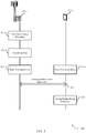
- FIG. 3 illustrates an example of a process flow 300 that supports beam management for various levels of beam correspondence in accordance with various aspects of the present disclosure.
- Process flow 300 may implement aspects of wireless communication system 100 or 200 as described with reference to FIG. 1 or 2 .
- Process flow 300 may include base station 105-b and UE 115-b, which may be examples of the corresponding devices of FIGs. 1 through 3 .
- Base station 105-b may be a mmW base station.
- base station 105-c may perform a first beam sweep procedure.
- base station 105-c may determine a first beam pair that includes a transmit beam of base station 105-c and a receive beam of UE 115-c.
- the first beam sweep procedure is based at least in part on a synchronization signal transmission procedure, or a beam reference signal, or a beam refinement reference signal, or a channel state information reference signal (CSI-RS), or a mobility reference signal procedure, or a combination thereof.
- CSI-RS channel state information reference signal
- base station 105-c may identify a level of correspondence.
- UE 115-c may identify a level of correspondence. That is, UE 115-c may be aware in advance its level of correspondence; for example, based on device (i.e., UE 115-c) calibration.
- UE 115-c or base station 105-c may determine, based on the first beam pair, a level of correspondence at one or both of the base station 105-c and UE 115-c.
- base station 105-c and UE 115-c may transmit a correspondence level indication associated with DL beams associated with base station 105-c or UL beams associated with UE 115-c.
- base station 105-c or UE 115-c may include the correspondence level indication in a MIB (e.g., bits reserved for indicating correspondence) or a SIB (e.g., bits reserved for indicating correspondence) transmitted to UE 115-c or base station 105-c.
- the base station 105-c or UE 115-c may transmit the MIB over a PBCH
- the base station 105-c or UE 115-c may transmit the SIB over an extended PBCH.
- UE 115-c may determine, based on the level of correspondence, a range for a second beam sweep procedure.
- the second beam sweep procedure may be based on a RACH, or a sounding reference signal (SRS), or a demodulation reference signal (DMRS) transmission procedure or a combination thereof.
- SRS sounding reference signal
- DMRS demodulation reference signal
- UE 115-c may be configured to transmit a number of SRS resources for UL beam management.
- the second beam sweep procedure may be performed to determine a second beam pair that includes a transmit beam of UE 115-c and a receive beam of base station 105-c.
- the determined range for the second beam sweep procedure may include a range of zero (e.g., no range), a complete or full range (such as the range used during the first beam sweep procedure), or a range that is in between zero and a full range (e.g., such as the range used for a partial beam sweep procedure).
- a range of zero e.g., no range
- a complete or full range such as the range used during the first beam sweep procedure
- a range that is in between zero and a full range e.g., such as the range used for a partial beam sweep procedure.
- FIG. 4 illustrates a block diagram 400 of a wireless device 405 that that supports beam management for various levels of beam correspondence in accordance with various aspects of the present disclosure.
- Wireless device 405 may be an example of aspects of a UE 115 or base station 105 as described with reference to FIG. 1 .
- Wireless device 405 may include receiver 410, beam correspondence manager 415, and transmitter 420.
- Wireless device 405 may also include a processor. Each of these components may be in communication with one another (e.g., via one or more buses).
- Receiver 410 may receive information such as packets, user data, or control information associated with various information channels (e.g., control channels, data channels, and information related to beam management in the presence of full/partial/no beam correspondence, etc.). Information may be passed on to other components of the device.
- information channels e.g., control channels, data channels, and information related to beam management in the presence of full/partial/no beam correspondence, etc.
- Beam correspondence manager 415 may perform a first beam sweep procedure to determine a first beam pair that includes a transmit beam of a first wireless node and a receive beam of a second wireless node, determine, based on the first beam pair, a level of correspondence at one or both of the first wireless node and the second wireless node, the level of correspondence being between a transmit beam and a receive beam of a respective wireless node, and determine, based on the level of correspondence, a range of a second beam sweep procedure to be performed in determining a second beam pair that includes a transmit beam of the second wireless node and a receive beam of the first wireless node.
- the first beam sweep procedure is based on a synchronization signal transmission procedure, or a beam reference signal, or a beam refinement reference signal, or a channel state information reference signal (CSI-RS), or a mobility reference signal procedure, or a combination thereof.
- CSI-RS channel state information reference signal
- Transmitter 420 may transmit signals generated by other components of the device.
- the transmitter 420 may be collocated with a receiver 410 in a transceiver module.
- the transmitter 420 may include a single antenna, or it may include a set of antennas.
- FIG. 5 illustrates a block diagram 500 of a wireless device 505 that supports beam management for various levels of beam correspondence in accordance with various aspects of the present disclosure.
- Wireless device 505 may be an example of aspects of a wireless device 405 or a UE 115 or base station 105 as described with reference to FIGs. 1 and 4 .
- Wireless device 505 may include receiver 510, beam correspondence manager 515, and transmitter 520.
- Wireless device 505 may also include a processor. Each of these components may be in communication with one another (e.g., via one or more buses).
- Receiver 510 may receive information such as packets, user data, or control information associated with various information channels (e.g., control channels, data channels, and information related to beam management in the presence of full/partial/no beam correspondence, etc.). Information may be passed on to other components of the device.
- the receiver 510 may be an example of aspects of the receiver 410 described with reference to FIG. 4 .
- Beam correspondence manager 515 may be an example of aspects of the beam correspondence manager 415 described with reference to FIG. 4 . Beam correspondence manager 515 may also include beam pair identification component 525, beam correspondence component 530, and beam sweep range component 535.
- Beam pair identification component 525 may perform a first beam sweep procedure to determine a first beam pair that includes a transmit beam of a first wireless node and a receive beam of a second wireless node.
- Beam correspondence component 530 may determine, based on the first beam pair, a level of correspondence at one or both of the first wireless node and the second wireless node, the level of correspondence being between a transmit beam and a receive beam of a respective wireless node.
- the second beam sweep is limited to a beam sweep at only one of the first wireless node or the second wireless node when the level of correspondence at the other of the first wireless node or the second wireless node is above an upper threshold.
- determining the level of correspondence at one or both of the first wireless node and the second wireless node includes: receiving one or more signals from which the level of correspondence is determined.
- Beam sweep range component 535 may determine, based on the level of correspondence, a range of a second beam sweep procedure to be performed in determining a second beam pair that includes a transmit beam of the second wireless node and a receive beam of the first wireless node.
- the range may include multiple thresholds, for example, different levels of inner thresholds that determine a level of correspondence for a partial beam sweep.
- a range may have a first threshold (e.g., ratios of an amplitude and phase error of a transmit path and a receive path).
- the first threshold may include within it multiple sub-thresholds (e.g., received signal strength, channel/link quality, etc.).
- beam sweep range component 535 may determine the range of the second beam sweep procedure to be performed based on a range of calibration values associated with a transmit path and a receive path of the at least one of the first wireless node or the second wireless node.
- the calibration values may indicate an amplitude and phase error of the transmit path and the receive path of base station 105 or UE 115.
- beam sweep range component 535 may determine the range of the second beam sweep procedure to be performed based on a range of beams that includes either the transmit beam of the first wireless node or the receive beam of the second wireless node of the first beam pair. Beam sweep range component 535, in some cases, may determine that the partial second beam sweep is to be performed is further based on whether the second wireless node is participating in an initial access with the first wireless node. Additionally or alternatively, beam sweep range component 535 may determine that the partial second beam sweep is to be performed is further based on whether the second wireless node is awaking in connected mode from a DRX cycle whose duration exceeds a threshold.
- beam sweep range component 535 may determine that the partial second beam sweep is to be performed is further based on whether the second wireless node is in an inactive state. In some cases, determining the range of the second beam sweep procedure to be performed in determining the second beam pair includes: determining that the range of the second beam sweep procedure is equal to a range of the first beam sweep procedure based on the level of correspondence being below a lower threshold.
- determining the range of the second beam sweep procedure to be performed in determining the second beam pair includes: determining that no second beam sweep is to be performed based on the level of correspondence being above an upper threshold. In some cases, determining the range of the second beam sweep procedure to be performed in determining the second beam pair includes: determining that a partial second beam sweep is to be performed based on the level of correspondence being above a lower threshold and below an upper threshold. In some cases, the first beam sweep procedure is part of a synchronization signal transmission procedure.
- Transmitter 520 may transmit signals generated by other components of the device.
- the transmitter 520 may be collocated with a receiver 510 in a transceiver module.
- the transmitter 520 may include a single antenna, or it may include a set of antennas
- FIG. 6 illustrates a block diagram 600 of a beam correspondence manager 615 that supports beam management for various levels of beam correspondence in accordance with various aspects of the present disclosure.
- the beam correspondence manager 615 may be an example of aspects of a beam correspondence manager 415 or beam correspondence manager 515 described with reference to FIGs. 4 and 5 .
- the beam correspondence manager 615 may include beam pair identification component 620, beam correspondence component 625, beam sweep range component 630, group link identification component 635, timing component 640, and beam coordination component 645. Each of these modules may communicate, directly or indirectly, with one another (e.g., via one or more buses).
- Beam pair identification component 620 may perform a first beam sweep procedure to determine a first beam pair that includes a transmit beam of a first wireless node and a receive beam of a second wireless node.
- Beam correspondence component 625 may determine, based on the first beam pair, a level of correspondence at one or both of the first wireless node and the second wireless node, the level of correspondence being between a transmit beam and a receive beam of a respective wireless node.
- the second beam sweep is limited to a beam sweep at only one of the first wireless node or the second wireless node when the level of correspondence at the other of the first wireless node or the second wireless node is above an upper threshold.
- determining the level of correspondence at one or both of the first wireless node and the second wireless node includes: receiving one or more signals from which the level of correspondence is determined.
- Beam sweep range component 630 may determine, based on the level of correspondence, a range of a second beam sweep procedure to be performed in determining a second beam pair that includes a transmit beam of the second wireless node and a receive beam of the first wireless node. In some examples, beam sweep range component 630 may determine the range of the second beam sweep procedure to be performed based on a range of calibration values associated with a transmit path and a receive path of the at least one of the first wireless node or the second wireless node.
- beam sweep range component 630 may determine the range of the second beam sweep procedure to be performed based on a range of beams that includes either the transmit beam of the first wireless node or the receive beam of the second wireless node of the first beam pair. In some cases, determining that the partial second beam sweep is to be performed is further based on whether the second wireless node is participating in an initial access with the first wireless node. Additionally or alternatively, determining that the partial second beam sweep is to be performed is further based on whether the second wireless node is awaking in connected mode from a DRX cycle whose duration exceeds a threshold. In some examples, determining that the partial second beam sweep is to be performed is further based on whether the second wireless node is in an inactive state.
- determining the range of the second beam sweep procedure to be performed in determining the second beam pair includes: determining that the range of the second beam sweep procedure is equal to a range of the first beam sweep procedure based on the level of correspondence being below a lower threshold. In some cases, determining the range of the second beam sweep procedure to be performed in determining the second beam pair includes: determining that no second beam sweep is to be performed based on the level of correspondence being above an upper threshold.
- determining the range of the second beam sweep procedure to be performed in determining the second beam pair includes: determining that a partial second beam sweep is to be performed based on the level of correspondence being above a lower threshold and below an upper threshold.
- the first beam sweep procedure is part of a synchronization signal transmission procedure.
- Group link identification component 635 may determine that the partial second beam sweep is to be performed is further based on an identification of a group of one or more links which share a same partial second beam sweep, identify the group of one or more links through communications between the first wireless node and the second wireless node, and reset the group of one or more links as part of a radio link failure (RLF) or handover procedure.
- RLF radio link failure
- the group of one or more links are associated with the first wireless node.
- Timing component 640 may determine that the partial second beam sweep is to be performed is further based on a verification that a timer associated with the use of the level of correspondence has expired and select a transmission time of a RACH signal based on the level of correspondence.
- Beam coordination component 645 may enable beam coordination between the first wireless node and one or more other wireless nodes when a level of correspondence at either the first wireless node or the second wireless node is less than an upper threshold.
- the beam coordination includes identification of beams to be reserved as downlink beams and identification of beams to be reserved as uplink beams
- FIG. 7 illustrates a diagram of a system 700 including a device 705 that supports beam management for various levels of beam correspondence in accordance with various aspects of the present disclosure.
- Device 705 may be an example of or include the components of wireless device 405, wireless device 505, or a UE 115 as described above, e.g., with reference to FIGs. 1 , 4 and 5 .
- Device 705 may include components for bidirectional voice and data communications including components for transmitting and receiving communications, including UE beam correspondence manager 715, processor 720, memory 725, software 730, transceiver 735, antenna 740, and I/O controller 745. These components may be in electronic communication via one or more busses (e.g., bus 710).
- Device 705 may communicate wirelessly with one or more base stations 105.
- Processor 720 may include an intelligent hardware device, (e.g., a general-purpose processor, a digital signal processor (DSP), a central processing unit (CPU), a microcontroller, an application-specific integrated circuit (ASIC), an field-programmable gate array (FPGA), a programmable logic device, a discrete gate or transistor logic component, a discrete hardware component, or any combination thereof).
- processor 720 may be configured to operate a memory array using a memory controller.
- a memory controller may be integrated into processor 720.
- Processor 720 may be configured to execute computer-readable instructions stored in a memory to perform various functions (e.g., functions or tasks supporting beam management in the presence of full/partial/no beam correspondence).
- Memory 725 may include random access memory (RAM) and read only memory (ROM).
- the memory 725 may store computer-readable, computer-executable software 730 including instructions that, when executed, cause the processor to perform various functions described herein.
- the memory 725 may contain, among other things, a basic input/output system (BIOS) which may control basic hardware and/or software operation such as the interaction with peripheral components or devices.
- BIOS basic input/output system
- Software 730 may include code to implement aspects of the present disclosure, including code to support beam management in the presence of full/partial/no beam correspondence.
- Software730 may be stored in a non-transitory computer-readable medium such as system memory or other memory. In some cases, the software 730 may not be directly executable by the processor but may cause a computer (e.g., when compiled and executed) to perform functions described herein.
- Transceiver 735 may communicate bi-directionally, via one or more antennas, wired, or wireless links as described above.
- the transceiver 735 may represent a wireless transceiver and may communicate bi-directionally with another wireless transceiver.
- the transceiver 735 may also include a modem to modulate the packets and provide the modulated packets to the antennas for transmission, and to demodulate packets received from the antennas.
- the wireless device may include a single antenna 740. However, in some cases the device may have more than one antenna 740, which may be capable of concurrently transmitting or receiving multiple wireless transmissions.
- I/O controller 745 may manage input and output signals for device 705. I/O controller 745 may also manage peripherals not integrated into device 705. In some cases, I/O controller 745 may represent a physical connection or port to an external peripheral. In some cases, I/O controller 745 may utilize an operating system such as iOS®, ANDROID®, MS-DOS®, MS-WINDOWS®, OS/2®, UNIX®, LINUX®, or another known operating system.
- an operating system such as iOS®, ANDROID®, MS-DOS®, MS-WINDOWS®, OS/2®, UNIX®, LINUX®, or another known operating system.
- FIG. 8 illustrates a diagram of a system 800 including a device 805 that supports beam management for various levels of beam correspondence in accordance with various aspects of the present disclosure.
- Device 805 may be an example of or include the components of wireless device 405, wireless device 505, or a base station 105 as described above, e.g., with reference to FIGs. 1 , 4 and 5 .
- Device 805 may include components for bidirectional voice and data communications including components for transmitting and receiving communications, including base station beam correspondence manager 815, processor 820, memory 825, software 830, transceiver 835, antenna 840, network communications manager 845, and base station communications manager 850. These components may be in electronic communication via one or more busses (e.g., bus 810).
- Device 805 may communicate wirelessly with one or more UEs 115.
- Processor 820 may include an intelligent hardware device, (e.g., a general-purpose processor, a DSP, a CPU, a microcontroller, an ASIC, an FPGA, a programmable logic device, a discrete gate or transistor logic component, a discrete hardware component, or any combination thereof).
- processor 820 may be configured to operate a memory array using a memory controller.
- a memory controller may be integrated into processor 820.
- Processor 820 may be configured to execute computer-readable instructions stored in a memory to perform various functions (e.g., functions or tasks supporting beam management in the presence of full/partial/no beam correspondence).
- Memory 825 may include RAM and ROM.
- the memory 825 may store computer-readable, computer-executable software 830 including instructions that, when executed, cause the processor to perform various functions described herein.
- the memory 825 may contain, among other things, a BIOS which may control basic hardware and/or software operation such as the interaction with peripheral components or devices.
- Software 830 may include code to implement aspects of the present disclosure, including code to support beam management in the presence of full/partial/no beam correspondence.
- Software 830 may be stored in a non-transitory computer-readable medium such as system memory or other memory. In some cases, the software 830 may not be directly executable by the processor but may cause a computer (e.g., when compiled and executed) to perform functions described herein.
- Transceiver 835 may communicate bi-directionally, via one or more antennas, wired, or wireless links as described above.
- the transceiver 835 may represent a wireless transceiver and may communicate bi-directionally with another wireless transceiver.
- the transceiver 835 may also include a modem to modulate the packets and provide the modulated packets to the antennas for transmission, and to demodulate packets received from the antennas.
- the wireless device may include a single antenna 840. However, in some cases the device may have more than one antenna 840, which may be capable of concurrently transmitting or receiving multiple wireless transmissions.
- Network communications manager 845 may manage communications with the core network (e.g., via one or more wired backhaul links). For example, the network communications manager 845 may manage the transfer of data communications for client devices, such as one or more UEs 115.
- Base station communications manager 850 may manage communications with other base station 105, and may include a controller or scheduler for controlling communications with UEs 115 in cooperation with other base stations 105. For example, the base station communications manager 850 may coordinate scheduling for transmissions to UEs 115 for various interference mitigation techniques such as beamforming or joint transmission. In some examples, base station communications manager 850 may provide an X2 interface within an Long Term Evolution (LTE)/LTE-A wireless communication network technology to provide communication between base stations 105.
- LTE Long Term Evolution
- LTE-A wireless communication network technology to provide communication between base stations 105.
- FIG. 9 illustrates a flowchart illustrating a method 900 that supports beam management for various levels of beam correspondence in accordance with various aspects of the present disclosure.
- the operations of method 900 may be implemented by a UE 115 or base station 105 or its components as described herein.
- the operations of method 900 may be performed by a beam correspondence manager as described with reference to FIGs. 4 through 6 .
- a UE 115 or base station 105 may execute a set of codes to control the functional elements of the device to perform the functions described below. Additionally or alternatively, the UE 115 or base station 105 may perform aspects of the functions described below using special-purpose hardware.
- UE 115 or base station 105 may perform a first beam sweep procedure to determine a first beam pair that includes a transmit beam of a first wireless node and a receive beam of a second wireless node.
- aspects of the operations of block 905 may be performed by a beam pair identification component as described with reference to FIGs. 5 and 6 .
- UE 115 or base station 105 may identify a level of correspondence at one or both of the first wireless node and the second wireless node, the level of correspondence being between a transmit beam and a receive beam of a respective wireless node.
- aspects of the operations of block 910 may be performed by a beam correspondence component as described with reference to FIGs. 5 and 6 .
- UE 115 or base station 105 may determine, based on the level of correspondence, a range of a second beam sweep procedure to be performed in determining a second beam pair that includes a transmit beam of the second wireless node and a receive beam of the first wireless node.
- aspects of the operations of block 915 may be performed by a beam sweep range component as described with reference to FIGs. 5 and 6 .
- FIG. 10 illustrates a flowchart illustrating a method 1000 that supports beam management for various levels of beam correspondence in accordance with various aspects of the present disclosure.
- the operations of method 1000 may be implemented by a UE 115 or base station 105 or its components as described herein.
- the operations of method 1000 may be performed by a beam correspondence manager as described with reference to FIGs. 4 through 6 .
- a UE 115 or base station 105 may execute a set of codes to control the functional elements of the device to perform the functions described below. Additionally or alternatively, the UE 115 or base station 105 may perform aspects of the functions described below using special-purpose hardware.
- UE 115 or base station 105 may perform a first beam sweep procedure to determine a first beam pair that includes a transmit beam of a first wireless node and a receive beam of a second wireless node.
- the operations of block 1005 may be performed according to the methods described with reference to FIG. 9 . In certain examples, aspects of the operations of block 1005 may be performed by a beam pair identification component as described with reference to FIGs.5 and 6 .
- UE 115 or base station 105 may identify a level of correspondence at one or both of the first wireless node and the second wireless node, the level of correspondence being between a transmit beam and a receive beam of a respective wireless node.
- the operations of block 1010 may be performed according to the methods described with reference to FIG. 9 . In certain examples, aspects of the operations of block 1010 may be performed by a beam correspondence component as described with reference to FIGs. 5 and 6 .
- UE 115 or base station 105 may determine, based on the level of correspondence, a range of a second beam sweep procedure to be performed in determining a second beam pair that includes a transmit beam of the second wireless node and a receive beam of the first wireless node.
- the operations of block 1015 may be performed according to the methods described with reference to FIG. 9 . In certain examples, aspects of the operations of block 1015 may be performed by a beam sweep range component as described with reference to FIGs. 5 and 6 .
- UE 115 or base station 105 may determine that a partial second beam sweep is to be performed based at least in part on the level of correspondence being above a lower threshold and below an upper threshold.
- the operations of block 1020 may be performed according to the methods described with reference to FIG. 9 . In certain examples, aspects of the operations of block 1020 may be performed by a beam sweep range component as described with reference to FIGs. 5 and 6 .
- FIG. 11 illustrates a flowchart illustrating a method 1100 that supports beam management for various levels of beam correspondence in accordance with various aspects of the present disclosure.
- the operations of method 1100 may be implemented by a UE 115 or base station 105 or its components as described herein.
- the operations of method 1100 may be performed by a beam correspondence manager as described with reference to FIGs. 4 through 6 .
- a UE 115 or base station 105 may execute a set of codes to control the functional elements of the device to perform the functions described below. Additionally or alternatively, the UE 115 or base station 105 may perform aspects of the functions described below using special-purpose hardware.
- UE 115 or base station 105 may perform a first beam sweep procedure to determine a first beam pair that includes a transmit beam of a first wireless node and a receive beam of a second wireless node.
- the operations of block 1105 may be performed according to the methods described with reference to FIGs. 9 and 10 . In certain examples, aspects of the operations of block 1105 may be performed by a beam pair identification component as described with reference to FIGs. 5 and 6 .
- UE 115 or base station 105 may identify a level of correspondence at one or both of the first wireless node and the second wireless node, the level of correspondence being between a transmit beam and a receive beam of a respective wireless node.
- the operations of block 1110 may be performed according to the methods described with reference to FIGs. 9 and 10 . In certain examples, aspects of the operations of block 1110 may be performed by a beam correspondence component as described with reference to FIGs. 5 and 6 .
- UE 115 or base station 105 may determine, based on the level of correspondence, a range of a second beam sweep procedure to be performed in determining a second beam pair that includes a transmit beam of the second wireless node and a receive beam of the first wireless node.
- the operations of block 1115 may be performed according to the methods described with reference to FIGs. 9 and 10 . In certain examples, aspects of the operations of block 1115 may be performed by a beam sweep range component as described with reference to FIGs. 5 and 6 .
- UE 115 or base station 105 may determine that a partial second beam sweep is to be performed is further based on an identification of a group of one or more links which share a same partial second beam sweep.
- the operations of block 1120 may be performed according to the methods described with reference to FIGs. 9 and 10 . In certain examples, aspects of the operations of block 1120 may be performed by a group link identification component as described with reference to FIG. 6 .
- UE 115 or base station 105 may determine that the partial second beam sweep is to be performed based at least in part on the level of correspondence being above a lower threshold and below an upper threshold.
- the operations of block 1125 may be performed according to the methods described with reference to FIGs. 9 and 10 . In certain examples, aspects of the operations of block 1125 may be performed by a group link identification component as described with reference to FIG. 6 .
- FIG. 12 illustrates a flowchart illustrating a method 1200 that supports beam management for various levels of beam correspondence in accordance with various aspects of the present disclosure.
- the operations of method 1200 may be implemented by a UE 115 or base station 105 or its components as described herein.
- the operations of method 1200 may be performed by a beam correspondence manager as described with reference to FIGs. 4 through 6 .
- a UE 115 or base station 105 may execute a set of codes to control the functional elements of the device to perform the functions described below. Additionally or alternatively, the UE 115 or base station 105 may perform aspects of the functions described below using special-purpose hardware.
- UE 115 or base station 105 may perform a first beam sweep procedure to determine a first beam pair that includes a transmit beam of a first wireless node and a receive beam of a second wireless node.
- the operations of block 1205 may be performed according to the methods described with reference to FIGs. 9 through 11 . In certain examples, aspects of the operations of block 1205 may be performed by a beam pair identification component as described with reference to FIGs. 5 and 6 .
- UE 115 or base station 105 may identify a level of correspondence at one or both of the first wireless node and the second wireless node, the level of correspondence being between a transmit beam and a receive beam of a respective wireless node.
- the operations of block 1210 may be performed according to the methods described with reference to FIGs. 9 through 11 . In certain examples, aspects of the operations of block 1210 may be performed by a beam correspondence component as described with reference to FIGs. 5 and 6 .
- UE 115 or base station 105 may determine, based on the level of correspondence, a range of a second beam sweep procedure to be performed in determining a second beam pair that includes a transmit beam of the second wireless node and a receive beam of the first wireless node.
- the operations of block 1215 may be performed according to the methods described with reference to FIGs. 9 through 11 . In certain examples, aspects of the operations of block 1215 may be performed by a beam sweep range component as described with reference to FIGs. 5 and 6 .
- UE 115 or base station 105 may determine that a partial second beam sweep is to be performed based at least in part on the level of correspondence being above a lower threshold and below an upper threshold.
- the operations of block 1220 may be performed according to the methods described with reference to FIGs. 9 through 11 . In certain examples, aspects of the operations of block 1220 may be performed by a timing component as described with reference to FIG. 6
- UE 115 or base station 105 may determine that the partial second beam sweep is to be performed is based on a verification that a timer associated with the use of the level of correspondence has expired.
- the operations of block 1225 may be performed according to the methods described with reference to FIGs. 9 through 11 . In certain examples, aspects of the operations of block 1225 may be performed by a timing component as described with reference to FIG. 6 .
- FIG. 13 illustrates a flowchart illustrating a method 1300 that supports beam management for various levels of beam correspondence in accordance with various aspects of the present disclosure.
- the operations of method 1300 may be implemented by a UE 115 or base station 105 or its components as described herein.
- the operations of method 1300 may be performed by a beam correspondence manager as described with reference to FIGs. 4 through 6 .
- a UE 115 or base station 105 may execute a set of codes to control the functional elements of the device to perform the functions described below. Additionally or alternatively, the UE 115 or base station 105 may perform aspects of the functions described below using special-purpose hardware.
- UE 115 or base station 105 may perform a first beam sweep procedure to determine a first beam pair that includes a transmit beam of a first wireless node and a receive beam of a second wireless node.
- the operations of block 1305 may be performed according to the methods described with reference to FIGs. 9 through 12 . In certain examples, aspects of the operations of block 1305 may be performed by a beam pair identification component as described with reference to FIGs. 5 and 6 .
- UE 115 or base station 105 may identify, a level of correspondence at one or both of the first wireless node and the second wireless node, the level of correspondence being between a transmit beam and a receive beam of a respective wireless node.
- the operations of block 1310 may be performed according to the methods described with reference to FIGs. 9 through 12 . In certain examples, aspects of the operations of block 1310 may be performed by a beam correspondence component as described with reference to FIGs. 5 and 6 .
- UE 115 or base station 105 may determine, based on the level of correspondence, a range of a second beam sweep procedure to be performed in determining a second beam pair that includes a transmit beam of the second wireless node and a receive beam of the first wireless node.
- the operations of block 1315 may be performed according to the methods described with reference to FIGs. 9 through 12 . In certain examples, aspects of the operations of block 1315 may be performed by a beam sweep range component as described with reference to FIG. 6 .
- UE 115 or base station 105 may enable beam coordination between the first wireless node and one or more other wireless nodes when a level of correspondence at either the first wireless node or the second wireless node is less than an upper threshold.
- the operations of block 1320 may be performed according to the methods described with reference to FIGs. 9 through 12 . In certain examples, aspects of the operations of block 1320 may be performed by a beam coordination component as described with reference to FIG. 6 .
- CDMA code division multiple access
- TDMA time division multiple access
- FDMA frequency division multiple access
- OFDMA orthogonal frequency division multiple access
- SC-FDMA single carrier frequency division multiple access
- CDMA2000 covers IS-2000, IS-95, and IS-856 standards.
- IS-2000 Releases may be commonly referred to as CDMA2000 IX, IX, etc.
- IS-856 (TIA-856) is commonly referred to as CDMA2000 lxEV-DO, High Rate Packet Data (HRPD), etc.
- UTRA includes Wideband CDMA (WCDMA) and other variants of CDMA.
- WCDMA Wideband CDMA
- a time division multiple access (TDMA) system may implement a radio technology such as Global System for Mobile Communications (GSM).
- GSM Global System for Mobile Communications
- An orthogonal frequency division multiple access (OFDMA) system may implement a radio technology such as Ultra Mobile Broadband (UMB), Evolved UTRA (E-UTRA), Institute of Electrical and Electronics Engineers (IEEE) 802.11 (Wi-Fi), IEEE 802.16 (WiMAX), IEEE 802.20, Flash-OFDM, etc.
- UMB Ultra Mobile Broadband
- E-UTRA Evolved UTRA
- IEEE Institute of Electrical and Electronics Engineers
- Wi-Fi Wi-Fi
- WiMAX IEEE 802.16
- IEEE 802.20 WiMAX
- Flash-OFDM Flash-OFDM
- UTRA, E-UTRA, UMTS, LTE, LTE-A, NR, and Global System for Mobile communications are described in documents from the organization named "3rd Generation Partnership Project” (3GPP).
- CDMA2000 and UMB are described in documents from an organization named "3rd Generation Partnership Project 2" (3GPP2).
- the techniques described herein may be used for the systems and radio technologies mentioned above as well as other systems and radio technologies. While aspects an LTE or an NR system may be described for purposes of example, and LTE or NR terminology may be used in much of the description, the techniques described herein are applicable beyond LTE or NR applications.
- the term evolved node B may be generally used to describe the base stations.
- the wireless communication system or systems described herein may include a heterogeneous LTE/LTE-A or NR network in which different types of evolved node B (eNBs) provide coverage for various geographical regions.
- eNBs evolved node B
- each eNB, gNB or base station may provide communication coverage for a macro cell, a small cell, or other types of cell.
- the term "cell” may be used to describe a base station, a carrier or component carrier associated with a base station, or a coverage area (e.g., sector, etc.) of a carrier or base station, depending on context.
- Base stations may include or may be referred to by those skilled in the art as a base transceiver station, a radio base station, an access point, a radio transceiver, a NodeB, eNodeB (eNB), next generation NodeB (gNB), Home NodeB, a Home eNodeB, or some other suitable terminology.
- the geographic coverage area for a base station may be divided into sectors making up only a portion of the coverage area.
- the wireless communication system or systems described herein may include base stations of different types (e.g., macro or small cell base stations).
- the UEs described herein may be able to communicate with various types of base stations and network equipment including macro eNBs, small cell eNBs, gNBs, relay base stations, and the like. There may be overlapping geographic coverage areas for different technologies.
- a macro cell generally covers a relatively large geographic area (e.g., several kilometers in radius) and may allow unrestricted access by UEs with service subscriptions with the network provider.
- a small cell is a lower-powered base station, as compared with a macro cell, that may operate in the same or different (e.g., licensed, unlicensed, etc.) frequency bands as macro cells.
- Small cells may include pico cells, femto cells, and micro cells according to various examples.
- a pico cell for example, may cover a small geographic area and may allow unrestricted access by UEs with service subscriptions with the network provider.
- a femto cell may also cover a small geographic area (e.g., a home) and may provide restricted access by UEs having an association with the femto cell (e.g., UEs in a CSG, UEs for users in the home, and the like).
- An eNB for a macro cell may be referred to as a macro eNB.
- An eNB for a small cell may be referred to as a small cell eNB, a pico eNB, a femto eNB, or a home eNB.
- An eNB may support one or multiple (e.g., two, three, four, and the like) cells (e.g., component carriers).
- the wireless communication system or systems described herein may support synchronous or asynchronous operation.
- the base stations may have similar frame timing, and transmissions from different base stations may be approximately aligned in time.
- the base stations may have different frame timing, and transmissions from different base stations may not be aligned in time.
- the techniques described herein may be used for either synchronous or asynchronous operations.
- Information and signals described herein may be represented using any of a variety of different technologies and techniques.
- data, instructions, commands, information, signals, bits, symbols, and chips that may be referenced throughout the above description may be represented by voltages, currents, electromagnetic waves, magnetic fields or particles, optical fields or particles, or any combination thereof.
- a general-purpose processor may be a microprocessor, but in the alternative, the processor may be any conventional processor, controller, microcontroller, or state machine.
- a processor may also be implemented as a combination of computing devices (e.g., a combination of a DSP and a microprocessor, multiple microprocessors, one or more microprocessors in conjunction with a DSP core, or any other such configuration).
- the functions described herein may be implemented in hardware, software executed by a processor, firmware, or any combination thereof. If implemented in software executed by a processor, the functions may be stored on or transmitted over as one or more instructions or code on a computer-readable medium. Other examples and implementations are within the scope of the disclosure and appended claims. For example, due to the nature of software, functions described above can be implemented using software executed by a processor, hardware, firmware, hardwiring, or combinations of any of these. Features implementing functions may also be physically located at various positions, including being distributed such that portions of functions are implemented at different physical locations.
- Computer-readable media includes both non-transitory computer storage media and communication media including any medium that facilitates transfer of a computer program from one place to another.
- a non-transitory storage medium may be any available medium that can be accessed by a general purpose or special purpose computer.
- non-transitory computer-readable media may comprise RAM, ROM, electrically erasable programmable read only memory (EEPROM), compact disk (CD) ROM or other optical disk storage, magnetic disk storage or other magnetic storage devices, or any other non-transitory medium that can be used to carry or store desired program code means in the form of instructions or data structures and that can be accessed by a general-purpose or special-purpose computer, or a general-purpose or special-purpose processor.
- RAM random access memory
- ROM read only memory
- EEPROM electrically erasable programmable read only memory
- CD compact disk
- magnetic disk storage or other magnetic storage devices or any other non-transitory medium that can be used to carry or store desired program code means in the form of instructions or data structures
- any connection is properly termed a computer-readable medium.
- the software is transmitted from a website, server, or other remote source using a coaxial cable, fiber optic cable, twisted pair, digital subscriber line (DSL), or wireless technologies such as infrared, radio, and microwave
- the coaxial cable, fiber optic cable, twisted pair, digital subscriber line (DSL), or wireless technologies such as infrared, radio, and microwave are included in the definition of medium.
- Disk and disc include CD, laser disc, optical disc, digital versatile disc (DVD), floppy disk and Blu-ray disc where disks usually reproduce data magnetically, while discs reproduce data optically with lasers. Combinations of the above are also included within the scope of computer-readable media.
Landscapes
- Engineering & Computer Science (AREA)
- Computer Networks & Wireless Communication (AREA)
- Signal Processing (AREA)
- Computer Security & Cryptography (AREA)
- Mobile Radio Communication Systems (AREA)
Applications Claiming Priority (3)
| Application Number | Priority Date | Filing Date | Title |
|---|---|---|---|
| US201662418086P | 2016-11-04 | 2016-11-04 | |
| US15/637,885 US10284278B2 (en) | 2016-11-04 | 2017-06-29 | Beam management for various levels of beam correspondence |
| PCT/US2017/055713 WO2018084999A1 (en) | 2016-11-04 | 2017-10-09 | Beam management for various levels of beam correspondence |
Publications (2)
| Publication Number | Publication Date |
|---|---|
| EP3535863A1 EP3535863A1 (en) | 2019-09-11 |
| EP3535863B1 true EP3535863B1 (en) | 2021-01-13 |
Family
ID=62064886
Family Applications (1)
| Application Number | Title | Priority Date | Filing Date |
|---|---|---|---|
| EP17788400.4A Active EP3535863B1 (en) | 2016-11-04 | 2017-10-09 | Beam management for various levels of beam correspondence |
Country Status (7)
| Country | Link |
|---|---|
| US (1) | US10284278B2 (enExample) |
| EP (1) | EP3535863B1 (enExample) |
| JP (1) | JP7013457B2 (enExample) |
| KR (1) | KR102543782B1 (enExample) |
| CN (1) | CN109891773B (enExample) |
| BR (1) | BR112019008909A2 (enExample) |
| WO (1) | WO2018084999A1 (enExample) |
Families Citing this family (41)
| Publication number | Priority date | Publication date | Assignee | Title |
|---|---|---|---|---|
| CN108282198B (zh) | 2017-01-06 | 2021-11-19 | 华为技术有限公司 | 一种信号传输方法和装置 |
| US10798588B2 (en) * | 2017-02-06 | 2020-10-06 | Mediatek Inc. | Mechanism for beam reciprocity determination and uplink beam management |
| US10211898B2 (en) | 2017-06-26 | 2019-02-19 | At&T Intellectual Property I, L.P. | Configurable beam failure event design |
| US10374683B2 (en) * | 2017-09-07 | 2019-08-06 | Futurewei Technologies, Inc. | Apparatus and method for beam failure recovery |
| US10735081B2 (en) * | 2017-09-13 | 2020-08-04 | Chiun Mai Communication Systems, Inc. | Heterogeneous network, mobile device and method for beam training and tracking |
| US10091662B1 (en) * | 2017-10-13 | 2018-10-02 | At&T Intellectual Property I, L.P. | Customer premises equipment deployment in beamformed wireless communication systems |
| EP3701637A1 (en) * | 2017-10-25 | 2020-09-02 | Telefonaktiebolaget LM Ericsson (PUBL) | Beam training of a radio transceiver device |
| US10827364B2 (en) | 2018-02-14 | 2020-11-03 | Futurewei Technologies, Inc. | Phased array antenna system for fast beam searching |
| US11038643B2 (en) * | 2018-02-27 | 2021-06-15 | Qualcomm Incorporated | Beam reporting for active beams |
| WO2020005121A1 (en) * | 2018-06-25 | 2020-01-02 | Telefonaktiebolaget Lm Ericsson (Publ) | Handling beam pairs in a wireless network |
| US11228353B2 (en) | 2018-08-09 | 2022-01-18 | Qualcomm Incorporated | Beamforming in non-reciprocal uplink and downlink channels |
| US10715238B2 (en) * | 2018-09-28 | 2020-07-14 | At&T Intellectual Property I, L.P. | Outcome based receiver beam tuning |
| US11349545B2 (en) | 2018-11-02 | 2022-05-31 | Apple Inc. | Beam management without beam correspondence |
| US11201662B2 (en) * | 2018-11-02 | 2021-12-14 | Apple Inc. | Uplink transmit beam sweep |
| US11579236B2 (en) * | 2018-11-21 | 2023-02-14 | Cisco Technology, Inc. | Partial phase vectors as network sensors |
| CN109644456B (zh) * | 2018-11-29 | 2023-10-10 | 北京小米移动软件有限公司 | 波束扫描范围确定方法、装置、设备及存储介质 |
| CN111294891B (zh) * | 2018-12-07 | 2021-06-22 | 成都华为技术有限公司 | 一种天线面板及波束的管理方法和设备 |
| WO2020155150A1 (zh) * | 2019-02-02 | 2020-08-06 | 北京小米移动软件有限公司 | 波束对应方法和装置、用户设备及基站 |
| CN113439410B (zh) * | 2019-02-15 | 2025-01-07 | 苹果公司 | 用于动态配置用户装备探测参考信号(srs)资源的系统和方法 |
| EP3963744A1 (en) * | 2019-04-30 | 2022-03-09 | Sony Group Corporation | Methods for enabling beam reference signalling, wireless devices and network nodes |
| US11496202B2 (en) * | 2019-05-16 | 2022-11-08 | Nxp Usa, Inc. | Fast and robust cell search for 5G and millimeter-wave wireless communication systems using joint frequency raster and receive beam search |
| CN112152686B (zh) | 2019-06-27 | 2023-09-26 | 中兴通讯股份有限公司 | 一种实现波束扫描与通信的方法、装置 |
| US11395155B2 (en) | 2019-07-05 | 2022-07-19 | Qualcomm Incorporated | Virtual serving beam tracking in millimeter wave wireless systems |
| US11082265B2 (en) | 2019-07-31 | 2021-08-03 | At&T Intellectual Property I, L.P. | Time synchronization of mobile channel sounding system |
| WO2021027763A1 (en) | 2019-08-12 | 2021-02-18 | Guangdong Oppo Mobile Telecommunications Corp., Ltd. | Method and device for beam determination for drx, ue and network device |
| US20220312225A1 (en) * | 2019-08-14 | 2022-09-29 | Samsung Electronics Co., Ltd. | Communication method, and user equipment and network equipment performing the communication method |
| US20210051557A1 (en) * | 2019-08-14 | 2021-02-18 | Qualcomm Incorporated | Communication procedure configuration for mobile network nodes |
| US11172533B2 (en) | 2019-08-29 | 2021-11-09 | Qualcomm Incorporated | Methods and apparatus to facilitate multi-tasking and smart location selection during connected-mode discontinuous reception mode |
| WO2021138816A1 (zh) * | 2020-01-07 | 2021-07-15 | Oppo广东移动通信有限公司 | 用于波束选择的方法、终端设备和网络设备 |
| WO2022015031A1 (en) * | 2020-07-13 | 2022-01-20 | Samsung Electronics Co., Ltd. | Method and apparatus for selecting beam pairs in a beamforming based communication system |
| EP3968532A1 (en) | 2020-09-14 | 2022-03-16 | Nokia Technologies Oy | User equipment beam correspondence |
| FI20206061A1 (en) | 2020-10-26 | 2022-04-27 | Nokia Technologies Oy | LINK BUDGET EVALUATION |
| WO2022241703A1 (en) * | 2021-05-20 | 2022-11-24 | Huawei Technologies Co., Ltd. | Methods and apparatus for communications using a reconfigurable intelligent surface |
| US12414117B2 (en) | 2021-08-04 | 2025-09-09 | Apple Inc. | Uplink transmission beam selection in a secondary cell |
| US12232184B2 (en) * | 2021-08-25 | 2025-02-18 | Qualcomm Incorporated | Uplink beam sweeping during random access procedures |
| WO2023044787A1 (zh) * | 2021-09-24 | 2023-03-30 | 北京小米移动软件有限公司 | 波束配置、确定方法、基站、信号中转设备和存储介质 |
| WO2023216211A1 (en) * | 2022-05-13 | 2023-11-16 | Telefonaktiebolaget Lm Ericsson (Publ) | Over the air calibration for an advanced antenna system |
| US20240007154A1 (en) * | 2022-06-30 | 2024-01-04 | Qualcomm Incorporated | Beamforming techniques in wi-fi frequency bands |
| US12457020B2 (en) * | 2022-09-19 | 2025-10-28 | Parsa Wireless Communications Llc | Intelligent downlink beamforming in a wireless communication network |
| US12463705B2 (en) * | 2023-06-02 | 2025-11-04 | Qualcomm Incorporated | Detection of near-field location for wireless communications |
| WO2025155790A1 (en) * | 2024-01-19 | 2025-07-24 | Matsing, Inc. | Rapid sequential area scanning with reduced beam interference |
Family Cites Families (11)
| Publication number | Priority date | Publication date | Assignee | Title |
|---|---|---|---|---|
| WO2008030806A2 (en) * | 2006-09-06 | 2008-03-13 | Qualcomm Incorporated | Codeword permutation and reduced feedback for grouped antennas |
| JP2009182441A (ja) | 2008-01-29 | 2009-08-13 | Mitsubishi Electric Corp | 通信装置およびキャリブレーション方法 |
| US8510433B2 (en) * | 2009-11-06 | 2013-08-13 | Nec Laboratories America, Inc. | Beam combination methods and systems for adapting communication links to varying channel conditions |
| KR101800221B1 (ko) | 2011-08-11 | 2017-11-22 | 삼성전자주식회사 | 무선통신 시스템에서 빔 추적 방법 및 장치 |
| KR101881847B1 (ko) * | 2012-02-21 | 2018-08-24 | 삼성전자주식회사 | 통신 시스템에서 신호를 송수신하는 방법 및 장치 |
| US9380582B2 (en) * | 2012-04-16 | 2016-06-28 | Samsung Electronics Co., Ltd. | Methods and apparatus for flexible beam communications in random access in system with large number of antennas |
| KR102071372B1 (ko) * | 2013-09-16 | 2020-01-30 | 삼성전자 주식회사 | 무선 통신 시스템에서 빔 포밍을 고려한 drx 제어 방법 및 장치 |
| CN105814808B (zh) * | 2014-11-17 | 2020-07-21 | 联发科技股份有限公司 | 波束成形方法和无线装置 |
| US9722726B2 (en) | 2015-03-28 | 2017-08-01 | Intel IP Corporation | Reciprocity detection and utilization techniques for beamforming training |
| CN107925457A (zh) | 2015-04-08 | 2018-04-17 | 株式会社Ntt都科摩 | 用于确定预编码矩阵的基站、用户装置和方法 |
| US10075985B2 (en) | 2015-08-17 | 2018-09-11 | Intel IP Corporation | Uplink synchronization with assisted mmWAVE enhanced node B |
-
2017
- 2017-06-29 US US15/637,885 patent/US10284278B2/en active Active
- 2017-10-09 JP JP2019520718A patent/JP7013457B2/ja active Active
- 2017-10-09 KR KR1020197011806A patent/KR102543782B1/ko active Active
- 2017-10-09 WO PCT/US2017/055713 patent/WO2018084999A1/en not_active Ceased
- 2017-10-09 EP EP17788400.4A patent/EP3535863B1/en active Active
- 2017-10-09 CN CN201780068020.4A patent/CN109891773B/zh active Active
- 2017-10-09 BR BR112019008909A patent/BR112019008909A2/pt unknown
Non-Patent Citations (1)
| Title |
|---|
| None * |
Also Published As
| Publication number | Publication date |
|---|---|
| US10284278B2 (en) | 2019-05-07 |
| WO2018084999A1 (en) | 2018-05-11 |
| JP2020500456A (ja) | 2020-01-09 |
| BR112019008909A2 (pt) | 2019-08-06 |
| US20180131434A1 (en) | 2018-05-10 |
| EP3535863A1 (en) | 2019-09-11 |
| CN109891773A (zh) | 2019-06-14 |
| JP7013457B2 (ja) | 2022-01-31 |
| CN109891773B (zh) | 2022-03-22 |
| KR20190075929A (ko) | 2019-07-01 |
| KR102543782B1 (ko) | 2023-06-14 |
Similar Documents
| Publication | Publication Date | Title |
|---|---|---|
| EP3535863B1 (en) | Beam management for various levels of beam correspondence | |
| US11304210B2 (en) | Indicating a range of beam correspondence in a wireless node | |
| US10728897B2 (en) | Uplink resources for beam recovery | |
| EP3497816B1 (en) | Rach conveyance of dl synchronization beam information for various dl-ul correspondence states | |
| KR20200007001A (ko) | 크로스-서브대역 의사 코로케이션 시그널링 | |
| WO2018063823A1 (en) | Use of downlink beam tracking results in reference symbol sessions | |
| US11671158B2 (en) | Determining beam failure based on a dynamic range of transmission power ratios | |
| EP3563622A1 (en) | Directional reception and periodic rts/cts transmission to estimate interference | |
| HK40075633A (en) | Uplink resources for beam recovery | |
| HK40013665A (en) | Uplink resources for beam recovery |
Legal Events
| Date | Code | Title | Description |
|---|---|---|---|
| STAA | Information on the status of an ep patent application or granted ep patent |
Free format text: STATUS: UNKNOWN |
|
| STAA | Information on the status of an ep patent application or granted ep patent |
Free format text: STATUS: THE INTERNATIONAL PUBLICATION HAS BEEN MADE |
|
| PUAI | Public reference made under article 153(3) epc to a published international application that has entered the european phase |
Free format text: ORIGINAL CODE: 0009012 |
|
| STAA | Information on the status of an ep patent application or granted ep patent |
Free format text: STATUS: REQUEST FOR EXAMINATION WAS MADE |
|
| 17P | Request for examination filed |
Effective date: 20190314 |
|
| AK | Designated contracting states |
Kind code of ref document: A1 Designated state(s): AL AT BE BG CH CY CZ DE DK EE ES FI FR GB GR HR HU IE IS IT LI LT LU LV MC MK MT NL NO PL PT RO RS SE SI SK SM TR |
|
| AX | Request for extension of the european patent |
Extension state: BA ME |
|
| DAV | Request for validation of the european patent (deleted) | ||
| DAX | Request for extension of the european patent (deleted) | ||
| STAA | Information on the status of an ep patent application or granted ep patent |
Free format text: STATUS: EXAMINATION IS IN PROGRESS |
|
| 17Q | First examination report despatched |
Effective date: 20200220 |
|
| GRAP | Despatch of communication of intention to grant a patent |
Free format text: ORIGINAL CODE: EPIDOSNIGR1 |
|
| STAA | Information on the status of an ep patent application or granted ep patent |
Free format text: STATUS: GRANT OF PATENT IS INTENDED |
|
| RIC1 | Information provided on ipc code assigned before grant |
Ipc: H04W 16/28 20090101ALI20200715BHEP Ipc: H04B 7/08 20060101ALI20200715BHEP Ipc: H04B 7/06 20060101AFI20200715BHEP Ipc: H04W 72/04 20090101ALI20200715BHEP |
|
| INTG | Intention to grant announced |
Effective date: 20200729 |
|
| GRAS | Grant fee paid |
Free format text: ORIGINAL CODE: EPIDOSNIGR3 |
|
| GRAA | (expected) grant |
Free format text: ORIGINAL CODE: 0009210 |
|
| STAA | Information on the status of an ep patent application or granted ep patent |
Free format text: STATUS: THE PATENT HAS BEEN GRANTED |
|
| AK | Designated contracting states |
Kind code of ref document: B1 Designated state(s): AL AT BE BG CH CY CZ DE DK EE ES FI FR GB GR HR HU IE IS IT LI LT LU LV MC MK MT NL NO PL PT RO RS SE SI SK SM TR |
|
| REG | Reference to a national code |
Ref country code: GB Ref legal event code: FG4D |
|
| REG | Reference to a national code |
Ref country code: CH Ref legal event code: EP |
|
| REG | Reference to a national code |
Ref country code: IE Ref legal event code: FG4D |
|
| REG | Reference to a national code |
Ref country code: DE Ref legal event code: R096 Ref document number: 602017031438 Country of ref document: DE |
|
| REG | Reference to a national code |
Ref country code: AT Ref legal event code: REF Ref document number: 1355324 Country of ref document: AT Kind code of ref document: T Effective date: 20210215 |
|
| REG | Reference to a national code |
Ref country code: AT Ref legal event code: MK05 Ref document number: 1355324 Country of ref document: AT Kind code of ref document: T Effective date: 20210113 |
|
| REG | Reference to a national code |
Ref country code: NL Ref legal event code: MP Effective date: 20210113 |
|
| REG | Reference to a national code |
Ref country code: LT Ref legal event code: MG9D |
|
| PG25 | Lapsed in a contracting state [announced via postgrant information from national office to epo] |
Ref country code: NO Free format text: LAPSE BECAUSE OF FAILURE TO SUBMIT A TRANSLATION OF THE DESCRIPTION OR TO PAY THE FEE WITHIN THE PRESCRIBED TIME-LIMIT Effective date: 20210413 Ref country code: PT Free format text: LAPSE BECAUSE OF FAILURE TO SUBMIT A TRANSLATION OF THE DESCRIPTION OR TO PAY THE FEE WITHIN THE PRESCRIBED TIME-LIMIT Effective date: 20210513 Ref country code: FI Free format text: LAPSE BECAUSE OF FAILURE TO SUBMIT A TRANSLATION OF THE DESCRIPTION OR TO PAY THE FEE WITHIN THE PRESCRIBED TIME-LIMIT Effective date: 20210113 Ref country code: HR Free format text: LAPSE BECAUSE OF FAILURE TO SUBMIT A TRANSLATION OF THE DESCRIPTION OR TO PAY THE FEE WITHIN THE PRESCRIBED TIME-LIMIT Effective date: 20210113 Ref country code: GR Free format text: LAPSE BECAUSE OF FAILURE TO SUBMIT A TRANSLATION OF THE DESCRIPTION OR TO PAY THE FEE WITHIN THE PRESCRIBED TIME-LIMIT Effective date: 20210414 Ref country code: BG Free format text: LAPSE BECAUSE OF FAILURE TO SUBMIT A TRANSLATION OF THE DESCRIPTION OR TO PAY THE FEE WITHIN THE PRESCRIBED TIME-LIMIT Effective date: 20210413 Ref country code: LT Free format text: LAPSE BECAUSE OF FAILURE TO SUBMIT A TRANSLATION OF THE DESCRIPTION OR TO PAY THE FEE WITHIN THE PRESCRIBED TIME-LIMIT Effective date: 20210113 |
|
| PG25 | Lapsed in a contracting state [announced via postgrant information from national office to epo] |
Ref country code: LV Free format text: LAPSE BECAUSE OF FAILURE TO SUBMIT A TRANSLATION OF THE DESCRIPTION OR TO PAY THE FEE WITHIN THE PRESCRIBED TIME-LIMIT Effective date: 20210113 Ref country code: PL Free format text: LAPSE BECAUSE OF FAILURE TO SUBMIT A TRANSLATION OF THE DESCRIPTION OR TO PAY THE FEE WITHIN THE PRESCRIBED TIME-LIMIT Effective date: 20210113 Ref country code: RS Free format text: LAPSE BECAUSE OF FAILURE TO SUBMIT A TRANSLATION OF THE DESCRIPTION OR TO PAY THE FEE WITHIN THE PRESCRIBED TIME-LIMIT Effective date: 20210113 Ref country code: AT Free format text: LAPSE BECAUSE OF FAILURE TO SUBMIT A TRANSLATION OF THE DESCRIPTION OR TO PAY THE FEE WITHIN THE PRESCRIBED TIME-LIMIT Effective date: 20210113 Ref country code: SE Free format text: LAPSE BECAUSE OF FAILURE TO SUBMIT A TRANSLATION OF THE DESCRIPTION OR TO PAY THE FEE WITHIN THE PRESCRIBED TIME-LIMIT Effective date: 20210113 |
|
| PG25 | Lapsed in a contracting state [announced via postgrant information from national office to epo] |
Ref country code: IS Free format text: LAPSE BECAUSE OF FAILURE TO SUBMIT A TRANSLATION OF THE DESCRIPTION OR TO PAY THE FEE WITHIN THE PRESCRIBED TIME-LIMIT Effective date: 20210513 |
|
| REG | Reference to a national code |
Ref country code: DE Ref legal event code: R097 Ref document number: 602017031438 Country of ref document: DE |
|
| PG25 | Lapsed in a contracting state [announced via postgrant information from national office to epo] |
Ref country code: SM Free format text: LAPSE BECAUSE OF FAILURE TO SUBMIT A TRANSLATION OF THE DESCRIPTION OR TO PAY THE FEE WITHIN THE PRESCRIBED TIME-LIMIT Effective date: 20210113 Ref country code: CZ Free format text: LAPSE BECAUSE OF FAILURE TO SUBMIT A TRANSLATION OF THE DESCRIPTION OR TO PAY THE FEE WITHIN THE PRESCRIBED TIME-LIMIT Effective date: 20210113 Ref country code: EE Free format text: LAPSE BECAUSE OF FAILURE TO SUBMIT A TRANSLATION OF THE DESCRIPTION OR TO PAY THE FEE WITHIN THE PRESCRIBED TIME-LIMIT Effective date: 20210113 |
|
| PLBE | No opposition filed within time limit |
Free format text: ORIGINAL CODE: 0009261 |
|
| STAA | Information on the status of an ep patent application or granted ep patent |
Free format text: STATUS: NO OPPOSITION FILED WITHIN TIME LIMIT |
|
| PG25 | Lapsed in a contracting state [announced via postgrant information from national office to epo] |
Ref country code: DK Free format text: LAPSE BECAUSE OF FAILURE TO SUBMIT A TRANSLATION OF THE DESCRIPTION OR TO PAY THE FEE WITHIN THE PRESCRIBED TIME-LIMIT Effective date: 20210113 Ref country code: SK Free format text: LAPSE BECAUSE OF FAILURE TO SUBMIT A TRANSLATION OF THE DESCRIPTION OR TO PAY THE FEE WITHIN THE PRESCRIBED TIME-LIMIT Effective date: 20210113 Ref country code: RO Free format text: LAPSE BECAUSE OF FAILURE TO SUBMIT A TRANSLATION OF THE DESCRIPTION OR TO PAY THE FEE WITHIN THE PRESCRIBED TIME-LIMIT Effective date: 20210113 |
|
| 26N | No opposition filed |
Effective date: 20211014 |
|
| PG25 | Lapsed in a contracting state [announced via postgrant information from national office to epo] |
Ref country code: AL Free format text: LAPSE BECAUSE OF FAILURE TO SUBMIT A TRANSLATION OF THE DESCRIPTION OR TO PAY THE FEE WITHIN THE PRESCRIBED TIME-LIMIT Effective date: 20210113 Ref country code: ES Free format text: LAPSE BECAUSE OF FAILURE TO SUBMIT A TRANSLATION OF THE DESCRIPTION OR TO PAY THE FEE WITHIN THE PRESCRIBED TIME-LIMIT Effective date: 20210113 |
|
| PG25 | Lapsed in a contracting state [announced via postgrant information from national office to epo] |
Ref country code: SI Free format text: LAPSE BECAUSE OF FAILURE TO SUBMIT A TRANSLATION OF THE DESCRIPTION OR TO PAY THE FEE WITHIN THE PRESCRIBED TIME-LIMIT Effective date: 20210113 |
|
| PG25 | Lapsed in a contracting state [announced via postgrant information from national office to epo] |
Ref country code: IT Free format text: LAPSE BECAUSE OF FAILURE TO SUBMIT A TRANSLATION OF THE DESCRIPTION OR TO PAY THE FEE WITHIN THE PRESCRIBED TIME-LIMIT Effective date: 20210113 |
|
| REG | Reference to a national code |
Ref country code: CH Ref legal event code: PL |
|
| PG25 | Lapsed in a contracting state [announced via postgrant information from national office to epo] |
Ref country code: IS Free format text: LAPSE BECAUSE OF FAILURE TO SUBMIT A TRANSLATION OF THE DESCRIPTION OR TO PAY THE FEE WITHIN THE PRESCRIBED TIME-LIMIT Effective date: 20210513 |
|
| REG | Reference to a national code |
Ref country code: BE Ref legal event code: MM Effective date: 20211031 |
|
| PG25 | Lapsed in a contracting state [announced via postgrant information from national office to epo] |
Ref country code: MC Free format text: LAPSE BECAUSE OF FAILURE TO SUBMIT A TRANSLATION OF THE DESCRIPTION OR TO PAY THE FEE WITHIN THE PRESCRIBED TIME-LIMIT Effective date: 20210113 |
|
| PG25 | Lapsed in a contracting state [announced via postgrant information from national office to epo] |
Ref country code: LU Free format text: LAPSE BECAUSE OF NON-PAYMENT OF DUE FEES Effective date: 20211009 Ref country code: BE Free format text: LAPSE BECAUSE OF NON-PAYMENT OF DUE FEES Effective date: 20211031 |
|
| PG25 | Lapsed in a contracting state [announced via postgrant information from national office to epo] |
Ref country code: LI Free format text: LAPSE BECAUSE OF NON-PAYMENT OF DUE FEES Effective date: 20211031 Ref country code: CH Free format text: LAPSE BECAUSE OF NON-PAYMENT OF DUE FEES Effective date: 20211031 |
|
| PG25 | Lapsed in a contracting state [announced via postgrant information from national office to epo] |
Ref country code: IE Free format text: LAPSE BECAUSE OF NON-PAYMENT OF DUE FEES Effective date: 20211009 |
|
| PG25 | Lapsed in a contracting state [announced via postgrant information from national office to epo] |
Ref country code: NL Free format text: LAPSE BECAUSE OF NON-PAYMENT OF DUE FEES Effective date: 20210113 Ref country code: CY Free format text: LAPSE BECAUSE OF FAILURE TO SUBMIT A TRANSLATION OF THE DESCRIPTION OR TO PAY THE FEE WITHIN THE PRESCRIBED TIME-LIMIT Effective date: 20210113 |
|
| PG25 | Lapsed in a contracting state [announced via postgrant information from national office to epo] |
Ref country code: HU Free format text: LAPSE BECAUSE OF FAILURE TO SUBMIT A TRANSLATION OF THE DESCRIPTION OR TO PAY THE FEE WITHIN THE PRESCRIBED TIME-LIMIT; INVALID AB INITIO Effective date: 20171009 |
|
| PG25 | Lapsed in a contracting state [announced via postgrant information from national office to epo] |
Ref country code: MK Free format text: LAPSE BECAUSE OF FAILURE TO SUBMIT A TRANSLATION OF THE DESCRIPTION OR TO PAY THE FEE WITHIN THE PRESCRIBED TIME-LIMIT Effective date: 20210113 |
|
| PG25 | Lapsed in a contracting state [announced via postgrant information from national office to epo] |
Ref country code: MT Free format text: LAPSE BECAUSE OF FAILURE TO SUBMIT A TRANSLATION OF THE DESCRIPTION OR TO PAY THE FEE WITHIN THE PRESCRIBED TIME-LIMIT Effective date: 20210113 |
|
| PGFP | Annual fee paid to national office [announced via postgrant information from national office to epo] |
Ref country code: DE Payment date: 20240913 Year of fee payment: 8 |
|
| PGFP | Annual fee paid to national office [announced via postgrant information from national office to epo] |
Ref country code: GB Payment date: 20250911 Year of fee payment: 9 |
|
| PGFP | Annual fee paid to national office [announced via postgrant information from national office to epo] |
Ref country code: FR Payment date: 20250912 Year of fee payment: 9 |