EP3534455A1 - Radio frequency filter having cavity structure - Google Patents
Radio frequency filter having cavity structure Download PDFInfo
- Publication number
- EP3534455A1 EP3534455A1 EP17864539.6A EP17864539A EP3534455A1 EP 3534455 A1 EP3534455 A1 EP 3534455A1 EP 17864539 A EP17864539 A EP 17864539A EP 3534455 A1 EP3534455 A1 EP 3534455A1
- Authority
- EP
- European Patent Office
- Prior art keywords
- cover
- housing
- radio frequency
- tuning
- groove
- Prior art date
- Legal status (The legal status is an assumption and is not a legal conclusion. Google has not performed a legal analysis and makes no representation as to the accuracy of the status listed.)
- Granted
Links
Images


Classifications
-
- H—ELECTRICITY
- H01—ELECTRIC ELEMENTS
- H01P—WAVEGUIDES; RESONATORS, LINES, OR OTHER DEVICES OF THE WAVEGUIDE TYPE
- H01P1/00—Auxiliary devices
- H01P1/20—Frequency-selective devices, e.g. filters
- H01P1/213—Frequency-selective devices, e.g. filters combining or separating two or more different frequencies
- H01P1/2138—Frequency-selective devices, e.g. filters combining or separating two or more different frequencies using hollow waveguide filters
-
- H—ELECTRICITY
- H01—ELECTRIC ELEMENTS
- H01P—WAVEGUIDES; RESONATORS, LINES, OR OTHER DEVICES OF THE WAVEGUIDE TYPE
- H01P7/00—Resonators of the waveguide type
- H01P7/06—Cavity resonators
-
- H—ELECTRICITY
- H01—ELECTRIC ELEMENTS
- H01P—WAVEGUIDES; RESONATORS, LINES, OR OTHER DEVICES OF THE WAVEGUIDE TYPE
- H01P1/00—Auxiliary devices
- H01P1/04—Fixed joints
-
- H—ELECTRICITY
- H01—ELECTRIC ELEMENTS
- H01P—WAVEGUIDES; RESONATORS, LINES, OR OTHER DEVICES OF THE WAVEGUIDE TYPE
- H01P1/00—Auxiliary devices
- H01P1/20—Frequency-selective devices, e.g. filters
- H01P1/201—Filters for transverse electromagnetic waves
- H01P1/205—Comb or interdigital filters; Cascaded coaxial cavities
- H01P1/2053—Comb or interdigital filters; Cascaded coaxial cavities the coaxial cavity resonators being disposed parall to each other
-
- H—ELECTRICITY
- H01—ELECTRIC ELEMENTS
- H01P—WAVEGUIDES; RESONATORS, LINES, OR OTHER DEVICES OF THE WAVEGUIDE TYPE
- H01P1/00—Auxiliary devices
- H01P1/20—Frequency-selective devices, e.g. filters
- H01P1/207—Hollow waveguide filters
-
- H—ELECTRICITY
- H01—ELECTRIC ELEMENTS
- H01P—WAVEGUIDES; RESONATORS, LINES, OR OTHER DEVICES OF THE WAVEGUIDE TYPE
- H01P1/00—Auxiliary devices
- H01P1/20—Frequency-selective devices, e.g. filters
- H01P1/207—Hollow waveguide filters
- H01P1/208—Cascaded cavities; Cascaded resonators inside a hollow waveguide structure
-
- H—ELECTRICITY
- H01—ELECTRIC ELEMENTS
- H01P—WAVEGUIDES; RESONATORS, LINES, OR OTHER DEVICES OF THE WAVEGUIDE TYPE
- H01P1/00—Auxiliary devices
- H01P1/20—Frequency-selective devices, e.g. filters
- H01P1/213—Frequency-selective devices, e.g. filters combining or separating two or more different frequencies
- H01P1/2133—Frequency-selective devices, e.g. filters combining or separating two or more different frequencies using coaxial filters
-
- H—ELECTRICITY
- H01—ELECTRIC ELEMENTS
- H01P—WAVEGUIDES; RESONATORS, LINES, OR OTHER DEVICES OF THE WAVEGUIDE TYPE
- H01P11/00—Apparatus or processes specially adapted for manufacturing waveguides or resonators, lines, or other devices of the waveguide type
-
- H—ELECTRICITY
- H01—ELECTRIC ELEMENTS
- H01P—WAVEGUIDES; RESONATORS, LINES, OR OTHER DEVICES OF THE WAVEGUIDE TYPE
- H01P11/00—Apparatus or processes specially adapted for manufacturing waveguides or resonators, lines, or other devices of the waveguide type
- H01P11/007—Manufacturing frequency-selective devices
-
- H—ELECTRICITY
- H01—ELECTRIC ELEMENTS
- H01P—WAVEGUIDES; RESONATORS, LINES, OR OTHER DEVICES OF THE WAVEGUIDE TYPE
- H01P11/00—Apparatus or processes specially adapted for manufacturing waveguides or resonators, lines, or other devices of the waveguide type
- H01P11/008—Manufacturing resonators
-
- H—ELECTRICITY
- H01—ELECTRIC ELEMENTS
- H01P—WAVEGUIDES; RESONATORS, LINES, OR OTHER DEVICES OF THE WAVEGUIDE TYPE
- H01P7/00—Resonators of the waveguide type
- H01P7/04—Coaxial resonators
-
- H—ELECTRICITY
- H01—ELECTRIC ELEMENTS
- H01P—WAVEGUIDES; RESONATORS, LINES, OR OTHER DEVICES OF THE WAVEGUIDE TYPE
- H01P7/00—Resonators of the waveguide type
- H01P7/10—Dielectric resonators
Definitions
- the present disclosure in some embodiments relates to a radio signal processing apparatus for use in a wireless communication system. More particularly, the present disclosure relates to a radio frequency filter having a cavity structure (hereinafter, abbreviated as 'filter'), such as a cavity filter.
- 'filter' a cavity structure
- a radio frequency filter having a cavity structure generally utilizes a metallic housing for providing a plurality of accommodation spaces or cavities having a shape such as rectangular parallelepiped and the like, in which dielectric resonance elements (DR) or resonance elements composed of a metallic resonance rod are each provided for generating superhigh frequency resonance. Further, such a radio frequency filter having a cavity structure is generally provided at its upper portion with a cover for shielding the open areas of the corresponding cavities, where the cover may have, as a configuration for tuning the filtering characteristic of the radio frequency filter, a plurality of tuning screws and nuts for fixing the corresponding tuning screws.
- An example radio frequency filter having a cavity structure is disclosed by Korean Patent Application Publication No. 10-2004-100084 (entitled “Radio Frequency Filter” and published on December 2, 2004; inventors: Park, Jonggyu and 2 others) filed by the present applicant.
- Radio frequency filters having such a cavity structure are used for processing radio transmit signals and receive signals in a radio communication system.
- the radio frequency filters are typically used for base stations, repeaters or relays and the like.
- Korean Patent Application Publication No. 10-2014-0026235 (entitled 'Radio Frequency Filter with Cavity Structure', published March 5, 2014, and invented by PARK, Nam Sin and 2 others) filed by the present applicant suggests a simplified filter structure for enabling easy frequency tuning without employing a coupling structure of tuning screws and fastening nuts.
- the above-mentioned Patent Application Publication No. 10-2014-0026235 suggests, when making a cover by pressing, die-casting or other processing of a plate-like base material of aluminum or magnesium material (including an alloy), to form one or more depressions at positions in the cover corresponding to resonance elements.
- a plurality of dot peen structures are formed at the depressions by embossing or pressing by embossing pins of an external embossing machine.
- Such a depression and dot peen structure are intended to replace the coupling structure of tuning screws and fastening nuts which have been conventionally used for frequency tuning, and to achieve appropriate tuning by narrowing the distance between the depression (and the dot peen structure) and the resonant element.
- the present disclosure in some embodiments seeks to provide a radio frequency filter having a cavity structure capable of tuning frequency without employing a conventional coupling structure of tuning screws and fastening nuts, which results in simpler manufacturing operations and lower manufacturing cost.
- the present disclosure in some embodiments aims to provide a radio frequency filter having a cavity structure in which tuning operations can be performed more easily, in addition to the above-mentioned object, by performing frequency tuning operations reversibly.
- At least one embodiment of the present disclosure provides a radio frequency filter having a cavity structure, and including a housing having internally a hollow space and an open side to provide at least one cavity, at least one resonance element located in the hollow space of the housing, a cover configured to have at least one groove which is internally threaded, recessed at a predetermined diameter and depth at a position corresponding to the resonance element, and has a bottom portion that is thinner than other portions, and to close the open side of the housing, and at least one frequency tuning screw configured to threadedly mate with the groove of the cover. When the frequency tuning screw threadedly mates with the groove, a bottom surface of the groove is depressed by the frequency tuning screw toward the resonant element.
- a radio frequency filter having a cavity structure, and including a housing having internally a hollow space and an open side to provide at least one cavity, at least one resonance element located in the hollow space of the housing, a cover configured to have at least one through hole which is internally threaded and has a predetermined diameter at a position corresponding to the resonance element, and has a bottom portion that is thinner than other portions, and to close the open side of the housing, a tuning metal plate disposed between the cover and the housing, and corresponding in size to the cover, and at least one frequency tuning screw configured to threadedly mate with the through hole of the cover. When the frequency tuning screw threadedly mates with the through hole, the tuning metal plate is depressed locally corresponding to and by the frequency tuning screw toward the resonant element.
- some embodiments of the present disclosure provide a radio frequency filter having a cavity structure for enabling frequency tuning without employing a conventional coupling structure of tuning screws and fastening nuts, results in simpler manufacturing operations and low-cost manufacturing. Further, in at least some other embodiments of the present disclosure, the frequency tuning operation can additionally be performed reversibly, facilitating the tuning operation.
- FIG. 1 is a partially cut-away sectional view of a radio frequency filter having a cavity structure according to the first embodiment of the present disclosure, in which a frequency tuning screw 31 is shown separated.
- FIG. 2 is the coupling of a separate part (i.e., the frequency tuning screw) in FIG. 1
- FIG. 3 is a perspective view of the frequency tuning screw of FIG 1 .
- the radio frequency filter having the cavity structure according to the first embodiment of the present disclosure similar to prior art, is provided with an enclosure that is hollow inside having at least one cavity shielded from the outside.
- the enclosure is formed including a housing 21 having at least one cavity and opened at one side (e.g., upper side), and a cover 11 for sealing the open side of the housing 21.
- the cavity formed in the housing 21 is centrally formed with a resonance element 41 which is fixedly installed on a bottom surface of the housing 21.
- the housing 21 forms, for example, a single cavity structure.
- the housing 21 may have a structure in which multiple cavities are connected in multiple stages, and each cavity may have a resonance element at its center.
- an input terminal and an output terminal of the RF filter may be formed on one side and the other side of the housing 21, respectively.
- the input and output terminals may be attached to the housing such that they are respectively connected to the input end cavity and output end cavity structures, respectively.
- the housing 21, the cavity structure formed by the housing 21 and the structure of the resonance element 41 may be configured similar to the conventional ones, and the housing 21 and the resonance element 41 may be made of aluminum (alloy) material.
- the cover 11 according to at least one embodiment of the present disclosure may be made of the same material as that of the housing 21, that is, an aluminum-based material.
- the cover 11 is formed with a groove 112 recessed at a predetermined diameter and depth at a portion corresponding to the resonance element 41 in the cavity of the housing 21.
- the thickness of a floor 'a' of the groove 112 is smaller than that of the rest of the cover 11, to form a thin membrane of the floor 'a'.
- the thickness of the floor of the groove 112 may be about 0.1 to 0.3 mm.
- the diameter of the groove 112 may be about 4.0 to 4.5 mm.
- the side surface of the groove 112 may be formed with a threaded coupling structure for coupling with the frequency tuning screw 31 for frequency tuning.
- the groove 112 generally has an internally threaded structure for allowing the frequency tuning screw 31 to be coupled in a threaded manner.
- the frequency tuning screw 31 has its side surface formed with an externally threaded structure for threadedly mating with the groove 112, and its top formed with a coupling groove 312 of a suitable shape for engaging an external driver device (driver, a wrench, etc.).
- the coupling groove 312 is shown in a slotted form.
- the frequency tuning screw 31 has a downward protrusion 313 at its bottom, that is, at a portion contacting the floor 'a' of the groove 112.
- the protrusion 313 may be formed to have a stepped shape so that the bottom of the frequency tuning screw 31 has a smaller diameter.
- the diameter of the frequency tuning screw 31 when the diameter of the frequency tuning screw 31 is about 4.0 to 4.5 mm, the diameter of the protrusion 313 may be about 2.5 to 3.5 mm.
- the protrusion 313 may be formed to have a height of about 0.5 to 1.0 mm.
- the frequency tuning screw 31 is engaged with and tightened against the groove 112 of the cover 11 during the frequency tuning operation.
- the protrusion 313 of the frequency tuning screw 31 pushes the floor 'a' of the groove 112.
- the floor 'a' of the groove 112 of the cover 11 is pushed toward the resonance element 41 inside its cavity, as shown more clearly in FIG. 2 .
- This adjusts the distance between the bottom of the cover 11, that is, the floor 'a' of the groove 112 and the resonance element 41 (i.e., d1 in FIG 1 and d2 in FIG. 2 ), which in turn adjusts the capacitance component between the cover 11 and the resonance element 41, and thereby adjusts the characteristic of the relevant filtering frequency.
- the total height of the frequency tuning screw 31 including the protrusion 313 is appropriately determined taking account of the thickness of the cover 11 and the condition of being tightened during the tuning operation, so that the frequency tuning operation is complete without leaving the top of the tuning screw 31 protruded from the upper surface of the cover 11. This can optimize the overall appearance and size of the filter.
- an adhesive resin such as epoxy may be applied to the mating site of the frequency tuning screw 31 with the groove 112 of the cover 11 and to maintain the fixed state of the frequency tuning screw 31.
- FIG. 4 is a partially cut-away sectional view of a radio frequency filter having a cavity structure according to a second embodiment of the present disclosure.
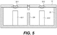
- FIG. 5 is shows the coupling of separate parts of FIG. 4 .
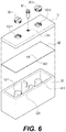
- FIG. 6 is a perspective view of FIG. 4 .
- a radio frequency filter according to the second embodiment of the present disclosure has, as with the structure of the first embodiment illustrated in FIGS. 1 to 3 , an enclosure including a housing 22 opened at the upper side, and a cover 12 for sealing the upper side of the housing 22.
- the housing 22 internally has cavities provided centrally with resonance elements 42-1 and 42-2 (collectively indicated by 42) which are fixedly mounted on the bottom surface of the housing 22.
- the housing 22 is illustrated as forming, for example, a structure having two cavities. Between the two cavities, a coupling window 224 is formed, which is a connecting passage structure for mutual coupling therebetween.
- the coupling window 224 may be formed in a partition wall disposed between the cavities as a corresponding void of a predetermined size.
- an input terminal of the relevant RF filter is provided to be connected to one of the two cavities of the housing 22, and an output terminal is provided to be connected to the other cavity.
- the cover 12 is provided with holes 122-1 and 122-2 (collectively indicated by 122) at portions corresponding to the respective resonance elements 42-1 and 42-2.
- the holes 122-1, 122-2 have a predetermined diameter and extend through the cover 12.
- the holes 122-1, 122-2 may have threaded side surfaces for threadedly mating with frequency tuning screws 32-1 and 32-2 (collectively indicated by 32) for frequency tuning.
- the holes 122 generally have an internally threaded structure for allowing the frequency tuning screws 32 to be coupled in a threaded manner.
- the frequency tuning screws 32 each has its side surface formed with an externally threaded structure for threadedly mating with the holes 122.
- the frequency tuning screws 32 are shown as having a generally uniform diameter from their upper ends to lower ends.
- the cover 12 and the housing 22 have therebetween, for example, a thin metal plate 62 disposed for the frequency tuning operation.
- the metal plate 62 may be made of, for example, aluminum, copper or iron-based material, and it may have a thickness of about 0.05 to 0.2 mm.
- the metal plate 62 may be fixedly attached to the cover 12 by a soldering method.
- solder or a solder cream at 'c' in FIG. 4 may be supplied to sites properly preset on the bottom surface of the cover 12, and a reflow soldering process or the like may be performed to solder the metal plate 62 and the cover 12 together.
- portions of the bottom surface of the metal plate 62 abutting the housing 22 may be fixedly attached to each other by a soldering method.
- the lower ends of the through holes 122 of the cover 12 may be formed with an auxiliary groove 'b' through an additional removal of edge portions of the through holes 122 to have their diameters relatively expanded. Accordingly, it can be seen that the through holes 122 are formed to have a stepped portion such that the lower ends partially have a wider diameter.
- the auxiliary groove 'b' is a structure for preventing the application of the solder cream, for example, during the soldering operation with the metal plate 62.
- the soldering operation may use a method of printing the solder cream on the lower surface of the cover 12. In such a case, the solder cream is prevented from being printed at the portion where the auxiliary groove 'b' is formed.
- clean portions of the metal plate 12 that are not soldered with the cover 12 due to auxiliary grooves 'b' of the through holes 122 include the sites contacted by the frequency tuning screws 32 with some tolerance added to the sites, which allows the corresponding areas of the metal plate 12 to the frequency tuning screws 32, to be pushed by the frequency tuning screws 32 by certain degrees.
- the frequency tuning screws 32 are coupled and tightened to the through holes 122 of the cover 12.
- the frequency tuning screws 32 are respectively tightened, the lower ends of the screws 32 pass through the holes 122 and then abut their corresponding portions on the upper surface of the metal plate 62 to depress the metal plate 62.
- the areas of the metal plate 62 corresponding to the tuning screws 32 are pushed toward the resonance elements 42 inside the cavity. This allows the distances to be adjusted between the lower surface of the metal plate 62 and the resonant elements 42, and thereby controls the characteristic of the filtering frequency.
- the tuning operation on the frequency characteristics can be performed by repeatedly tightening or untightening the tuning screws 32.
- the total height of the frequency tuning screw 32 is appropriately determined taking account of the thickness of the cover 12 and the condition of being tightened during the tuning operation, so that the frequency tuning operation is complete without at least leaving the top of the tuning screws 32 protruded from the upper surface of the cover 12.
- a coupling tuning screw 52 for coupling between cavities is provided on the cover 12, in addition to the frequency tuning screws 32.
- the coupling tuning screw 52 may be formed to be threadedly screwed into a screw hole 124 formed in the cover 12 at the position corresponding to the coupling window 224, so that it may protrude toward the coupling window 224.
- a through hole 622 is formed in the corresponding portion of the metal plate 62 so that the coupling tuning screw 52 can protrude toward the coupling window 224.
- the radio frequency filter may be configured as illustrated by some embodiments of the present disclosure, and other various embodiments and modifications may be made in the present disclosure.
- the frequency tuning screws 32 according to the second embodiment shown in FIGS. 4 to 6 may be configured to further have protrusions which are formed at their lower ends as shown in FIGS. 1 to 3 .
- the through holes 122 formed in the cover 120 shown in FIGS. 4 to 6 can be configured without the auxiliary grooves 'b' being formed at the lower ends thereof.
- the resonant elements may be made as separate components to be attached to the internal floor of the housing of the radio frequency filter. Since the housing and the resonant element may be made of the same material, they can be integrally formed by a die casting method. Alternatively, as in the technique disclosed by the above-mentioned Patent Application Publication No. 10-2014-0026235 , the housing and the resonance element inside the housing may be integrally formed by a pressing process as a whole.
Landscapes
- Engineering & Computer Science (AREA)
- Manufacturing & Machinery (AREA)
- Physics & Mathematics (AREA)
- Electromagnetism (AREA)
- Control Of Motors That Do Not Use Commutators (AREA)
- Casings For Electric Apparatus (AREA)
Abstract
Description
- The present disclosure in some embodiments relates to a radio signal processing apparatus for use in a wireless communication system. More particularly, the present disclosure relates to a radio frequency filter having a cavity structure (hereinafter, abbreviated as 'filter'), such as a cavity filter.
- A radio frequency filter having a cavity structure generally utilizes a metallic housing for providing a plurality of accommodation spaces or cavities having a shape such as rectangular parallelepiped and the like, in which dielectric resonance elements (DR) or resonance elements composed of a metallic resonance rod are each provided for generating superhigh frequency resonance. Further, such a radio frequency filter having a cavity structure is generally provided at its upper portion with a cover for shielding the open areas of the corresponding cavities, where the cover may have, as a configuration for tuning the filtering characteristic of the radio frequency filter, a plurality of tuning screws and nuts for fixing the corresponding tuning screws. An example radio frequency filter having a cavity structure is disclosed by Korean Patent Application Publication No.
10-2004-100084 - Radio frequency filters having such a cavity structure are used for processing radio transmit signals and receive signals in a radio communication system. Particularly in mobile communication systems, the radio frequency filters are typically used for base stations, repeaters or relays and the like.
- Meanwhile, Korean Patent Application Publication No.
10-2014-0026235 10-2014-0026235 - The technique disclosed by the above-mentioned Patent Application Publication No.
10-2014-0026235 - However, the technique disclosed by the above-mentioned Patent Application Publication No.
10-2014-0026235 - The present disclosure in some embodiments seeks to provide a radio frequency filter having a cavity structure capable of tuning frequency without employing a conventional coupling structure of tuning screws and fastening nuts, which results in simpler manufacturing operations and lower manufacturing cost.
- Further, the present disclosure in some embodiments aims to provide a radio frequency filter having a cavity structure in which tuning operations can be performed more easily, in addition to the above-mentioned object, by performing frequency tuning operations reversibly.
- At least one embodiment of the present disclosure provides a radio frequency filter having a cavity structure, and including a housing having internally a hollow space and an open side to provide at least one cavity, at least one resonance element located in the hollow space of the housing, a cover configured to have at least one groove which is internally threaded, recessed at a predetermined diameter and depth at a position corresponding to the resonance element, and has a bottom portion that is thinner than other portions, and to close the open side of the housing, and at least one frequency tuning screw configured to threadedly mate with the groove of the cover. When the frequency tuning screw threadedly mates with the groove, a bottom surface of the groove is depressed by the frequency tuning screw toward the resonant element.
- Another embodiment of the present disclosure provides a radio frequency filter having a cavity structure, and including a housing having internally a hollow space and an open side to provide at least one cavity, at least one resonance element located in the hollow space of the housing, a cover configured to have at least one through hole which is internally threaded and has a predetermined diameter at a position corresponding to the resonance element, and has a bottom portion that is thinner than other portions, and to close the open side of the housing, a tuning metal plate disposed between the cover and the housing, and corresponding in size to the cover, and at least one frequency tuning screw configured to threadedly mate with the through hole of the cover. When the frequency tuning screw threadedly mates with the through hole, the tuning metal plate is depressed locally corresponding to and by the frequency tuning screw toward the resonant element.
- As described above, some embodiments of the present disclosure provide a radio frequency filter having a cavity structure for enabling frequency tuning without employing a conventional coupling structure of tuning screws and fastening nuts, results in simpler manufacturing operations and low-cost manufacturing. Further, in at least some other embodiments of the present disclosure, the frequency tuning operation can additionally be performed reversibly, facilitating the tuning operation.
-
-
FIG. 1 is a partially cut-away sectional view of a radio frequency filter having a cavity structure according to a first embodiment of the present disclosure. -
FIG. 2 shows the coupling of a separate part ofFIG 1 . -
FIG. 3 is a perspective view of a frequency tuning screw ofFIG 1 . -
FIG. 4 is a partially cut-away sectional view of a radio frequency filter having a cavity structure according to a second embodiment of the present disclosure. -
FIG. 5 shows the coupling of separate parts ofFIG 4 . -
FIG. 6 is a perspective view ofFIG. 4 . - Hereinafter, some embodiments of the present disclosure will be described in detail with reference to the accompanying drawings. In the following description, like reference numerals designate like elements, although the elements are shown in different drawings. Further, in the following description of some embodiments, the size and shape of the same are somewhat simplified or partially exaggerated for convenience of explanation.
-
FIG. 1 is a partially cut-away sectional view of a radio frequency filter having a cavity structure according to the first embodiment of the present disclosure, in which afrequency tuning screw 31 is shown separated.FIG. 2 is the coupling of a separate part (i.e., the frequency tuning screw) inFIG. 1 , andFIG. 3 is a perspective view of the frequency tuning screw ofFIG 1 . Referring toFIGS. 1 to 3 , the radio frequency filter having the cavity structure according to the first embodiment of the present disclosure, similar to prior art, is provided with an enclosure that is hollow inside having at least one cavity shielded from the outside. The enclosure is formed including ahousing 21 having at least one cavity and opened at one side (e.g., upper side), and acover 11 for sealing the open side of thehousing 21. The cavity formed in thehousing 21 is centrally formed with aresonance element 41 which is fixedly installed on a bottom surface of thehousing 21. - The example illustrated in
FIGS. 1 to 3 shows, for convenience of explanation, that thehousing 21 forms, for example, a single cavity structure. However, in addition to this structure, thehousing 21 may have a structure in which multiple cavities are connected in multiple stages, and each cavity may have a resonance element at its center. Although not shown inFIGS. 1 to 3 , an input terminal and an output terminal of the RF filter may be formed on one side and the other side of thehousing 21, respectively. When the housing is configured to have multiple cavities, the input and output terminals may be attached to the housing such that they are respectively connected to the input end cavity and output end cavity structures, respectively. - In this configuration, the
housing 21, the cavity structure formed by thehousing 21 and the structure of theresonance element 41 may be configured similar to the conventional ones, and thehousing 21 and theresonance element 41 may be made of aluminum (alloy) material. In addition, thecover 11 according to at least one embodiment of the present disclosure may be made of the same material as that of thehousing 21, that is, an aluminum-based material. - The
cover 11 is formed with agroove 112 recessed at a predetermined diameter and depth at a portion corresponding to theresonance element 41 in the cavity of thehousing 21. The thickness of a floor 'a' of thegroove 112 is smaller than that of the rest of thecover 11, to form a thin membrane of the floor 'a'. For example, when the thickness of the rest of thecover 11 is about 2.0 to 3.0 mm, the thickness of the floor of thegroove 112 may be about 0.1 to 0.3 mm. In addition, the diameter of thegroove 112 may be about 4.0 to 4.5 mm. - The side surface of the
groove 112 may be formed with a threaded coupling structure for coupling with thefrequency tuning screw 31 for frequency tuning. In other words, thegroove 112 generally has an internally threaded structure for allowing thefrequency tuning screw 31 to be coupled in a threaded manner. - The
frequency tuning screw 31 has its side surface formed with an externally threaded structure for threadedly mating with thegroove 112, and its top formed with acoupling groove 312 of a suitable shape for engaging an external driver device (driver, a wrench, etc.). In the example ofFIGS. 1 to 3 , thecoupling groove 312 is shown in a slotted form. Thefrequency tuning screw 31 has adownward protrusion 313 at its bottom, that is, at a portion contacting the floor 'a' of thegroove 112. Theprotrusion 313 may be formed to have a stepped shape so that the bottom of thefrequency tuning screw 31 has a smaller diameter. For example, when the diameter of thefrequency tuning screw 31 is about 4.0 to 4.5 mm, the diameter of theprotrusion 313 may be about 2.5 to 3.5 mm. Theprotrusion 313 may be formed to have a height of about 0.5 to 1.0 mm. - In the above-described filter structure, the
frequency tuning screw 31 is engaged with and tightened against thegroove 112 of thecover 11 during the frequency tuning operation. When thefrequency tuning screw 31 is tightened, theprotrusion 313 of thefrequency tuning screw 31 pushes the floor 'a' of thegroove 112. As a result, the floor 'a' of thegroove 112 of thecover 11 is pushed toward theresonance element 41 inside its cavity, as shown more clearly inFIG. 2 . This adjusts the distance between the bottom of thecover 11, that is, the floor 'a' of thegroove 112 and the resonance element 41 (i.e., d1 inFIG 1 and d2 inFIG. 2 ), which in turn adjusts the capacitance component between thecover 11 and theresonance element 41, and thereby adjusts the characteristic of the relevant filtering frequency. - At this time, where the floor 'a' of the
groove 112 of thecover 11 is designed to have some elasticity, one can repeatedly tighten or untighten thefrequency tuning screw 31 to perform the frequency property tuning. - The total height of the
frequency tuning screw 31 including theprotrusion 313 is appropriately determined taking account of the thickness of thecover 11 and the condition of being tightened during the tuning operation, so that the frequency tuning operation is complete without leaving the top of thetuning screw 31 protruded from the upper surface of thecover 11. This can optimize the overall appearance and size of the filter. - After the frequency tuning operation is completed, an adhesive resin (not shown) such as epoxy may be applied to the mating site of the
frequency tuning screw 31 with thegroove 112 of thecover 11 and to maintain the fixed state of thefrequency tuning screw 31. -
FIG. 4 is a partially cut-away sectional view of a radio frequency filter having a cavity structure according to a second embodiment of the present disclosure.FIG. 5 is shows the coupling of separate parts ofFIG. 4 .FIG. 6 is a perspective view ofFIG. 4 . Referring toFIGS. 4 to 6 , a radio frequency filter according to the second embodiment of the present disclosure has, as with the structure of the first embodiment illustrated inFIGS. 1 to 3 , an enclosure including ahousing 22 opened at the upper side, and acover 12 for sealing the upper side of thehousing 22. Thehousing 22 internally has cavities provided centrally with resonance elements 42-1 and 42-2 (collectively indicated by 42) which are fixedly mounted on the bottom surface of thehousing 22. - In the example of
FIGS. 4 to 6 , thehousing 22 is illustrated as forming, for example, a structure having two cavities. Between the two cavities, acoupling window 224 is formed, which is a connecting passage structure for mutual coupling therebetween. Thecoupling window 224 may be formed in a partition wall disposed between the cavities as a corresponding void of a predetermined size. Although not shown inFIGS. 4 to 6 , an input terminal of the relevant RF filter is provided to be connected to one of the two cavities of thehousing 22, and an output terminal is provided to be connected to the other cavity. - In the filter according to the second embodiment of the present disclosure having the above structure, the
cover 12 is provided with holes 122-1 and 122-2 (collectively indicated by 122) at portions corresponding to the respective resonance elements 42-1 and 42-2. The holes 122-1, 122-2 have a predetermined diameter and extend through thecover 12. The holes 122-1, 122-2 may have threaded side surfaces for threadedly mating with frequency tuning screws 32-1 and 32-2 (collectively indicated by 32) for frequency tuning. In other words, the holes 122 generally have an internally threaded structure for allowing the frequency tuning screws 32 to be coupled in a threaded manner. - The frequency tuning screws 32 each has its side surface formed with an externally threaded structure for threadedly mating with the holes 122. Here, in the example shown in
FIGS. 4 to 6 , the frequency tuning screws 32 are shown as having a generally uniform diameter from their upper ends to lower ends. - In the structure of the second embodiment shown in
FIGS. 4 to 6 , thecover 12 and thehousing 22 have therebetween, for example, athin metal plate 62 disposed for the frequency tuning operation. Themetal plate 62 may be made of, for example, aluminum, copper or iron-based material, and it may have a thickness of about 0.05 to 0.2 mm. - The
metal plate 62 may be fixedly attached to thecover 12 by a soldering method. For example, solder or a solder cream at 'c' inFIG. 4 may be supplied to sites properly preset on the bottom surface of thecover 12, and a reflow soldering process or the like may be performed to solder themetal plate 62 and thecover 12 together. Likewise, portions of the bottom surface of themetal plate 62 abutting thehousing 22 may be fixedly attached to each other by a soldering method. - The lower ends of the through holes 122 of the
cover 12 may be formed with an auxiliary groove 'b' through an additional removal of edge portions of the through holes 122 to have their diameters relatively expanded. Accordingly, it can be seen that the through holes 122 are formed to have a stepped portion such that the lower ends partially have a wider diameter. - The auxiliary groove 'b' is a structure for preventing the application of the solder cream, for example, during the soldering operation with the
metal plate 62. For example, the soldering operation may use a method of printing the solder cream on the lower surface of thecover 12. In such a case, the solder cream is prevented from being printed at the portion where the auxiliary groove 'b' is formed. As described above, clean portions of themetal plate 12 that are not soldered with thecover 12 due to auxiliary grooves 'b' of the through holes 122 include the sites contacted by the frequency tuning screws 32 with some tolerance added to the sites, which allows the corresponding areas of themetal plate 12 to the frequency tuning screws 32, to be pushed by the frequency tuning screws 32 by certain degrees. - With the above-described filter structure, in the frequency tuning operation, the frequency tuning screws 32 are coupled and tightened to the through holes 122 of the
cover 12. As the frequency tuning screws 32 are respectively tightened, the lower ends of the screws 32 pass through the holes 122 and then abut their corresponding portions on the upper surface of themetal plate 62 to depress themetal plate 62. As a result, as shown more clearly inFIG. 5 , the areas of themetal plate 62 corresponding to the tuning screws 32 are pushed toward the resonance elements 42 inside the cavity. This allows the distances to be adjusted between the lower surface of themetal plate 62 and the resonant elements 42, and thereby controls the characteristic of the filtering frequency. - Meanwhile, in case where the
metal plate 62 has certain elasticity, the tuning operation on the frequency characteristics can be performed by repeatedly tightening or untightening the tuning screws 32. - In addition, the total height of the frequency tuning screw 32 is appropriately determined taking account of the thickness of the
cover 12 and the condition of being tightened during the tuning operation, so that the frequency tuning operation is complete without at least leaving the top of the tuning screws 32 protruded from the upper surface of thecover 12. - On the other hand, in the embodiment of
FIGS. 4 to 6 , a coupling tuning screw 52 for coupling between cavities is provided on thecover 12, in addition to the frequency tuning screws 32. In other words, thecoupling tuning screw 52 may be formed to be threadedly screwed into ascrew hole 124 formed in thecover 12 at the position corresponding to thecoupling window 224, so that it may protrude toward thecoupling window 224. - In the above structure, a through
hole 622 is formed in the corresponding portion of themetal plate 62 so that thecoupling tuning screw 52 can protrude toward thecoupling window 224. - As described above, the radio frequency filter may be configured as illustrated by some embodiments of the present disclosure, and other various embodiments and modifications may be made in the present disclosure. For example, although the above description states that the frequency tuning screws 32 according to the second embodiment shown in
FIGS. 4 to 6 have a generally uniform diameter, they may be configured to further have protrusions which are formed at their lower ends as shown inFIGS. 1 to 3 . In this case, the through holes 122 formed in the cover 120 shown inFIGS. 4 to 6 can be configured without the auxiliary grooves 'b' being formed at the lower ends thereof. - In addition, the resonant elements may be made as separate components to be attached to the internal floor of the housing of the radio frequency filter. Since the housing and the resonant element may be made of the same material, they can be integrally formed by a die casting method. Alternatively, as in the technique disclosed by the above-mentioned Patent Application Publication No.
10-2014-0026235 - It should be understood that the detailed structure, size, and the like of specifically detailed components such as frequency tuning screws, grooves, through holes, etc., as well as the number and type of cavities provided in the enclosure can be variously changed.
- Therefore, various modifications and variations of the present disclosure can be made without departing from the idea and scope of the present disclosure as defined by the appended claims and their equivalents rather than the particularly illustrated embodiments.
- This application claims priority under 35 U.S.C §119(a) of Patent Application No.
10-2016-0139478, filed on October 25, 2016
Claims (6)
- A radio frequency filter having a cavity structure, the radio frequency filter comprising:a housing having internally a hollow space and an open side to provide at least one cavity;at least one resonance element located in the hollow space of the housing;a cover configuredto have at least one groove which is internally threaded, recessed at a predetermined diameter and depth at a position corresponding to the resonance element, and has a bottom portion that is thinner than other portions, andto close the open side of the housing; andat least one frequency tuning screw configured to threadedly mate with the groove of the cover,wherein when the frequency tuning screw threadedly mates with the groove, a bottom surface of the groove is depressed by the frequency tuning screw toward the resonant element.
- A radio frequency filter having a cavity structure, the radio frequency filter comprising:a housing having internally a hollow space and an open side to provide at least one cavity;at least one resonance element located in the hollow space of the housing;a cover configuredto have at least one through hole which is internally threaded and has a predetermined diameter at a position corresponding to the resonance element, and has a bottom portion that is thinner than other portions, andto close the open side of the housing;a tuning metal plate disposed between the cover and the housing, and corresponding in size to the cover; andat least one frequency tuning screw configured to threadedly mate with the through hole of the cover,wherein when the frequency tuning screw threadedly mates with the through hole, the tuning metal plate is depressed locally corresponding to and by the frequency tuning screw toward the resonant element.
- The radio frequency filter of claim 1 or 2, wherein the frequency tuning screw has a lower end formed with a protrusion which protrudes downward.
- The radio frequency filter of claim 2, wherein the through hole of the cover has a lower end of formed with a stepped portion so as to have a larger diameter than a diameter of other portions.
- The radio frequency filter of claim 2 or 4, wherein the tuning metal plate is fixedly attached to the cover by a soldering method.
- The radio frequency filter of claim 2 or 4, wherein
the housing has at least two cavities,
the at least two cavities has a coupling window formed as a connection passage between the cavities,
the cover has a screw hole formed in the cover at a position corresponding to the coupling window,
the metal plate is provided with a through hole for coupling tuning at a position corresponding to the screw hole formed in the cover, and
a coupling tuning screw, which threadedly mates with the screw hole, protrudes toward the coupling window through the screw hole and the through hole for coupling tuning.
Applications Claiming Priority (2)
| Application Number | Priority Date | Filing Date | Title |
|---|---|---|---|
| KR1020160139478A KR102642238B1 (en) | 2016-10-25 | 2016-10-25 | Radio frequency filter with cavity structure |
| PCT/KR2017/011444 WO2018080078A1 (en) | 2016-10-25 | 2017-10-17 | Radio frequency filter having cavity structure |
Publications (3)
| Publication Number | Publication Date |
|---|---|
| EP3534455A1 true EP3534455A1 (en) | 2019-09-04 |
| EP3534455A4 EP3534455A4 (en) | 2020-05-27 |
| EP3534455B1 EP3534455B1 (en) | 2023-08-23 |
Family
ID=62023864
Family Applications (1)
| Application Number | Title | Priority Date | Filing Date |
|---|---|---|---|
| EP17864539.6A Active EP3534455B1 (en) | 2016-10-25 | 2017-10-17 | Radio frequency filter having cavity structure |
Country Status (7)
| Country | Link |
|---|---|
| US (1) | US10998603B2 (en) |
| EP (1) | EP3534455B1 (en) |
| JP (1) | JP7171554B2 (en) |
| KR (1) | KR102642238B1 (en) |
| CN (2) | CN116053737B (en) |
| FI (1) | FI3534455T3 (en) |
| WO (1) | WO2018080078A1 (en) |
Families Citing this family (12)
| Publication number | Priority date | Publication date | Assignee | Title |
|---|---|---|---|---|
| KR101954641B1 (en) * | 2017-04-11 | 2019-03-07 | 주식회사 에이스테크놀로지 | RF Cavity Filter Having Tuning Structure Using Elastic Body |
| US10505244B2 (en) | 2017-03-17 | 2019-12-10 | Ace Technologies Corporation | RF cavity filter using elastic element and method for manufacturing the same |
| KR102034603B1 (en) * | 2017-12-29 | 2019-10-21 | 주식회사 에이스테크놀로지 | RF Cavity Filter Using High elasticity Plate Elastic Body and Method for Producing the Same in Order to Prohibit Inflow of Debris |
| KR102077476B1 (en) * | 2018-04-13 | 2020-02-17 | 주식회사 에이스테크놀로지 | RF Cavity Filter Robust to Degradation Due to PIMD and Method for Producing the Same |
| CN110518317A (en) * | 2019-09-23 | 2019-11-29 | 石家庄滤通微波科技有限公司 | A kind of implementation method of no screw small cavity filter |
| CN113131168B (en) * | 2019-12-31 | 2026-01-16 | 大富科技(安徽)股份有限公司 | Cavity filter debugging device |
| CN111129670B (en) * | 2020-01-13 | 2025-01-03 | 迈特通信设备(苏州)有限公司 | A metal filter for 5G communication technology |
| KR102919910B1 (en) * | 2020-07-09 | 2026-01-29 | 삼성전자주식회사 | Antenna filter and electronic device inlcuding the same |
| KR102440354B1 (en) * | 2020-09-14 | 2022-09-05 | 주식회사 에이스테크놀로지 | RF Cavity Filter Having a Cover Where Tuning Structure is Integrated |
| WO2022108378A1 (en) * | 2020-11-20 | 2022-05-27 | 주식회사 케이엠더블유 | Rf module for antenna, rf module assembly, and antenna apparatus comprising same |
| CN114006138A (en) * | 2021-10-14 | 2022-02-01 | 苏州市协诚微波技术有限公司 | Cavity type filter and self-locking tuning screw for cavity type filter |
| CN114784470B (en) * | 2022-05-09 | 2025-10-03 | 大富科技(安徽)股份有限公司 | Filter, communication device, and filter manufacturing method |
Family Cites Families (24)
| Publication number | Priority date | Publication date | Assignee | Title |
|---|---|---|---|---|
| JPS5027869Y1 (en) * | 1970-05-13 | 1975-08-18 | ||
| JPH1188006A (en) * | 1997-09-16 | 1999-03-30 | Alps Electric Co Ltd | Dielectric filter and electronic unit having the same |
| SE519554C2 (en) * | 1999-04-14 | 2003-03-11 | Ericsson Telefon Ab L M | Screw device and trim device comprising such a screw device for trimming the frequency ratio or degree of coupling of a cavity filter |
| JP3531570B2 (en) * | 2000-03-14 | 2004-05-31 | 株式会社村田製作所 | Resonator, filter, duplexer, communication equipment |
| JP2004241843A (en) * | 2003-02-03 | 2004-08-26 | Fujitsu Ltd | Filter device provided in outdoor electronic device and outdoor electronic device |
| KR100489698B1 (en) | 2003-05-21 | 2005-05-17 | 주식회사 케이엠더블유 | Radio frequency filter |
| JP2009253944A (en) * | 2008-04-11 | 2009-10-29 | Panasonic Corp | Filter adjustment support apparatus, filter adjustment support method used in the same, and filter adjusting method using these |
| KR101072284B1 (en) * | 2008-08-01 | 2011-10-11 | 주식회사 케이엠더블유 | Dielectric resonator in radio frequency filter and assembling thereof |
| KR101082641B1 (en) | 2009-06-26 | 2011-11-10 | 원광대학교산학협력단 | Method of polygonal pyramid element generation |
| KR20110000320U (en) * | 2009-07-06 | 2011-01-13 | 신갑재 | The structure of Resonator with two-stage tuning screw |
| KR101140729B1 (en) * | 2009-12-24 | 2012-05-03 | 주식회사 이롬테크 | Dielectric resonator filter |
| CN202259614U (en) * | 2010-10-29 | 2012-05-30 | 深圳市大富科技股份有限公司 | Cavity filter and communication equipment |
| CN101976750A (en) * | 2010-10-29 | 2011-02-16 | 深圳市大富科技股份有限公司 | Cavity filter |
| CN102324616A (en) * | 2011-07-28 | 2012-01-18 | 西安空间无线电技术研究所 | Super power microwave resonator structure |
| KR101307107B1 (en) * | 2011-11-08 | 2013-09-11 | 주식회사 에이스테크놀로지 | Dielectric Resonator Filter |
| CN103296351B (en) * | 2012-02-29 | 2019-02-22 | 深圳光启创新技术有限公司 | a filter |
| KR102010269B1 (en) | 2012-08-23 | 2019-08-13 | 주식회사 케이엠더블유 | Radio frequency filter with cavity structure |
| CN103107389A (en) * | 2012-11-16 | 2013-05-15 | 深圳市大富科技股份有限公司 | Cavity filter |
| CN103872419A (en) * | 2012-12-11 | 2014-06-18 | 中兴通讯股份有限公司 | Medium resonator and assembling method thereof, and medium filter |
| CN203134747U (en) * | 2013-02-27 | 2013-08-14 | 中国电子科技集团公司第十二研究所 | Adjustable filter loading double gap coupling broadband output apparatus |
| KR20150049452A (en) * | 2013-10-30 | 2015-05-08 | 한국전자통신연구원 | Rf cavity filter which comprises tunning bolt holding member and said tunning bold holding member |
| KR101693214B1 (en) * | 2014-10-28 | 2017-01-05 | 주식회사 케이엠더블유 | Radio frequency filter with cavity structure |
| CN204315704U (en) * | 2014-12-26 | 2015-05-06 | 东莞鸿爱斯通信科技有限公司 | Dielectric resonator |
| CN204927465U (en) * | 2015-09-07 | 2015-12-30 | 李登峰 | Cavity filter that reliability is high |
-
2016
- 2016-10-25 KR KR1020160139478A patent/KR102642238B1/en active Active
-
2017
- 2017-10-17 FI FIEP17864539.6T patent/FI3534455T3/en active
- 2017-10-17 CN CN202310170655.2A patent/CN116053737B/en active Active
- 2017-10-17 EP EP17864539.6A patent/EP3534455B1/en active Active
- 2017-10-17 CN CN201780063691.1A patent/CN109845028B/en active Active
- 2017-10-17 WO PCT/KR2017/011444 patent/WO2018080078A1/en not_active Ceased
- 2017-10-17 JP JP2019520385A patent/JP7171554B2/en active Active
-
2019
- 2019-04-24 US US16/393,758 patent/US10998603B2/en active Active
Also Published As
| Publication number | Publication date |
|---|---|
| KR20180045413A (en) | 2018-05-04 |
| CN109845028B (en) | 2023-03-17 |
| US20190252750A1 (en) | 2019-08-15 |
| CN116053737A (en) | 2023-05-02 |
| KR102642238B1 (en) | 2024-03-04 |
| CN109845028A (en) | 2019-06-04 |
| CN116053737B (en) | 2025-07-11 |
| JP2019531664A (en) | 2019-10-31 |
| JP7171554B2 (en) | 2022-11-15 |
| US10998603B2 (en) | 2021-05-04 |
| EP3534455B1 (en) | 2023-08-23 |
| FI3534455T3 (en) | 2023-11-20 |
| WO2018080078A1 (en) | 2018-05-03 |
| EP3534455A4 (en) | 2020-05-27 |
Similar Documents
| Publication | Publication Date | Title |
|---|---|---|
| US10998603B2 (en) | Radio frequency filter having cavity structure | |
| US9716301B2 (en) | Radio frequency filter having a hollow box with a wrinkle structure and including a resonance element disposed therein which is short-circuited to the box by a pin | |
| CN107210506B (en) | RF filter with cavity structure | |
| KR20150118768A (en) | Radio frequency filter with cavity structure | |
| CN108701886A (en) | Cavity RF Filter with Cross-Coupled Notch Structure | |
| KR101728152B1 (en) | Cavity Type Wireless Frequency Filter And Method For Manufacturing The Same | |
| KR200482481Y1 (en) | Radio frequency filter | |
| KR102422720B1 (en) | Cavity type radio frequency filter | |
| KR101730084B1 (en) | Radio frequency filter with cavity structure | |
| CN214411483U (en) | Single-cavity resonator and radio frequency cavity filter | |
| EP0533394A2 (en) | Filter comprising a resonator rod mounted on a base plate | |
| KR20150028372A (en) | Ceramic Resonator and Filter using thereof | |
| CN101573788B (en) | Attachment of deep drawn resonator shell | |
| JP2005086532A (en) | Dielectric resonator and dielectric bandpass filter | |
| CN105280994A (en) | TM mode dielectric filter and multiplexer | |
| JPH04337903A (en) | Antenna | |
| JP2762877B2 (en) | Cavities for optical microwave resonators | |
| JP2006129317A (en) | Non-reciprocal circuit element |
Legal Events
| Date | Code | Title | Description |
|---|---|---|---|
| STAA | Information on the status of an ep patent application or granted ep patent |
Free format text: STATUS: THE INTERNATIONAL PUBLICATION HAS BEEN MADE |
|
| PUAI | Public reference made under article 153(3) epc to a published international application that has entered the european phase |
Free format text: ORIGINAL CODE: 0009012 |
|
| STAA | Information on the status of an ep patent application or granted ep patent |
Free format text: STATUS: REQUEST FOR EXAMINATION WAS MADE |
|
| 17P | Request for examination filed |
Effective date: 20190424 |
|
| AK | Designated contracting states |
Kind code of ref document: A1 Designated state(s): AL AT BE BG CH CY CZ DE DK EE ES FI FR GB GR HR HU IE IS IT LI LT LU LV MC MK MT NL NO PL PT RO RS SE SI SK SM TR |
|
| AX | Request for extension of the european patent |
Extension state: BA ME |
|
| DAV | Request for validation of the european patent (deleted) | ||
| DAX | Request for extension of the european patent (deleted) | ||
| REG | Reference to a national code |
Ref country code: DE Free format text: PREVIOUS MAIN CLASS: H01P0001207000 Ref country code: DE Ref legal event code: R079 Ref document number: 602017073243 Country of ref document: DE Free format text: PREVIOUS MAIN CLASS: H01P0001207000 Ipc: H01P0001205000 |
|
| A4 | Supplementary search report drawn up and despatched |
Effective date: 20200424 |
|
| RIC1 | Information provided on ipc code assigned before grant |
Ipc: H01P 7/06 20060101ALI20200420BHEP Ipc: H01P 1/205 20060101AFI20200420BHEP Ipc: H01P 7/04 20060101ALI20200420BHEP Ipc: H01P 1/208 20060101ALI20200420BHEP Ipc: H01P 11/00 20060101ALI20200420BHEP |
|
| STAA | Information on the status of an ep patent application or granted ep patent |
Free format text: STATUS: EXAMINATION IS IN PROGRESS |
|
| 17Q | First examination report despatched |
Effective date: 20210927 |
|
| GRAP | Despatch of communication of intention to grant a patent |
Free format text: ORIGINAL CODE: EPIDOSNIGR1 |
|
| STAA | Information on the status of an ep patent application or granted ep patent |
Free format text: STATUS: GRANT OF PATENT IS INTENDED |
|
| INTG | Intention to grant announced |
Effective date: 20230316 |
|
| GRAS | Grant fee paid |
Free format text: ORIGINAL CODE: EPIDOSNIGR3 |
|
| GRAA | (expected) grant |
Free format text: ORIGINAL CODE: 0009210 |
|
| STAA | Information on the status of an ep patent application or granted ep patent |
Free format text: STATUS: THE PATENT HAS BEEN GRANTED |
|
| AK | Designated contracting states |
Kind code of ref document: B1 Designated state(s): AL AT BE BG CH CY CZ DE DK EE ES FI FR GB GR HR HU IE IS IT LI LT LU LV MC MK MT NL NO PL PT RO RS SE SI SK SM TR |
|
| REG | Reference to a national code |
Ref country code: GB Ref legal event code: FG4D |
|
| REG | Reference to a national code |
Ref country code: CH Ref legal event code: EP |
|
| REG | Reference to a national code |
Ref country code: IE Ref legal event code: FG4D |
|
| REG | Reference to a national code |
Ref country code: DE Ref legal event code: R096 Ref document number: 602017073243 Country of ref document: DE |
|
| REG | Reference to a national code |
Ref country code: FI Ref legal event code: FGE |
|
| REG | Reference to a national code |
Ref country code: SE Ref legal event code: TRGR |
|
| REG | Reference to a national code |
Ref country code: LT Ref legal event code: MG9D |
|
| REG | Reference to a national code |
Ref country code: NL Ref legal event code: MP Effective date: 20230823 |
|
| REG | Reference to a national code |
Ref country code: AT Ref legal event code: MK05 Ref document number: 1603658 Country of ref document: AT Kind code of ref document: T Effective date: 20230823 |
|
| PG25 | Lapsed in a contracting state [announced via postgrant information from national office to epo] |
Ref country code: GR Free format text: LAPSE BECAUSE OF FAILURE TO SUBMIT A TRANSLATION OF THE DESCRIPTION OR TO PAY THE FEE WITHIN THE PRESCRIBED TIME-LIMIT Effective date: 20231124 |
|
| PG25 | Lapsed in a contracting state [announced via postgrant information from national office to epo] |
Ref country code: IS Free format text: LAPSE BECAUSE OF FAILURE TO SUBMIT A TRANSLATION OF THE DESCRIPTION OR TO PAY THE FEE WITHIN THE PRESCRIBED TIME-LIMIT Effective date: 20231223 |
|
| PG25 | Lapsed in a contracting state [announced via postgrant information from national office to epo] |
Ref country code: RS Free format text: LAPSE BECAUSE OF FAILURE TO SUBMIT A TRANSLATION OF THE DESCRIPTION OR TO PAY THE FEE WITHIN THE PRESCRIBED TIME-LIMIT Effective date: 20230823 Ref country code: PT Free format text: LAPSE BECAUSE OF FAILURE TO SUBMIT A TRANSLATION OF THE DESCRIPTION OR TO PAY THE FEE WITHIN THE PRESCRIBED TIME-LIMIT Effective date: 20231226 Ref country code: NO Free format text: LAPSE BECAUSE OF FAILURE TO SUBMIT A TRANSLATION OF THE DESCRIPTION OR TO PAY THE FEE WITHIN THE PRESCRIBED TIME-LIMIT Effective date: 20231123 Ref country code: NL Free format text: LAPSE BECAUSE OF FAILURE TO SUBMIT A TRANSLATION OF THE DESCRIPTION OR TO PAY THE FEE WITHIN THE PRESCRIBED TIME-LIMIT Effective date: 20230823 Ref country code: LV Free format text: LAPSE BECAUSE OF FAILURE TO SUBMIT A TRANSLATION OF THE DESCRIPTION OR TO PAY THE FEE WITHIN THE PRESCRIBED TIME-LIMIT Effective date: 20230823 Ref country code: LT Free format text: LAPSE BECAUSE OF FAILURE TO SUBMIT A TRANSLATION OF THE DESCRIPTION OR TO PAY THE FEE WITHIN THE PRESCRIBED TIME-LIMIT Effective date: 20230823 Ref country code: IS Free format text: LAPSE BECAUSE OF FAILURE TO SUBMIT A TRANSLATION OF THE DESCRIPTION OR TO PAY THE FEE WITHIN THE PRESCRIBED TIME-LIMIT Effective date: 20231223 Ref country code: HR Free format text: LAPSE BECAUSE OF FAILURE TO SUBMIT A TRANSLATION OF THE DESCRIPTION OR TO PAY THE FEE WITHIN THE PRESCRIBED TIME-LIMIT Effective date: 20230823 Ref country code: GR Free format text: LAPSE BECAUSE OF FAILURE TO SUBMIT A TRANSLATION OF THE DESCRIPTION OR TO PAY THE FEE WITHIN THE PRESCRIBED TIME-LIMIT Effective date: 20231124 Ref country code: AT Free format text: LAPSE BECAUSE OF FAILURE TO SUBMIT A TRANSLATION OF THE DESCRIPTION OR TO PAY THE FEE WITHIN THE PRESCRIBED TIME-LIMIT Effective date: 20230823 |
|
| PG25 | Lapsed in a contracting state [announced via postgrant information from national office to epo] |
Ref country code: PL Free format text: LAPSE BECAUSE OF FAILURE TO SUBMIT A TRANSLATION OF THE DESCRIPTION OR TO PAY THE FEE WITHIN THE PRESCRIBED TIME-LIMIT Effective date: 20230823 |
|
| PG25 | Lapsed in a contracting state [announced via postgrant information from national office to epo] |
Ref country code: ES Free format text: LAPSE BECAUSE OF FAILURE TO SUBMIT A TRANSLATION OF THE DESCRIPTION OR TO PAY THE FEE WITHIN THE PRESCRIBED TIME-LIMIT Effective date: 20230823 |
|
| PG25 | Lapsed in a contracting state [announced via postgrant information from national office to epo] |
Ref country code: SM Free format text: LAPSE BECAUSE OF FAILURE TO SUBMIT A TRANSLATION OF THE DESCRIPTION OR TO PAY THE FEE WITHIN THE PRESCRIBED TIME-LIMIT Effective date: 20230823 Ref country code: RO Free format text: LAPSE BECAUSE OF FAILURE TO SUBMIT A TRANSLATION OF THE DESCRIPTION OR TO PAY THE FEE WITHIN THE PRESCRIBED TIME-LIMIT Effective date: 20230823 Ref country code: ES Free format text: LAPSE BECAUSE OF FAILURE TO SUBMIT A TRANSLATION OF THE DESCRIPTION OR TO PAY THE FEE WITHIN THE PRESCRIBED TIME-LIMIT Effective date: 20230823 Ref country code: EE Free format text: LAPSE BECAUSE OF FAILURE TO SUBMIT A TRANSLATION OF THE DESCRIPTION OR TO PAY THE FEE WITHIN THE PRESCRIBED TIME-LIMIT Effective date: 20230823 Ref country code: DK Free format text: LAPSE BECAUSE OF FAILURE TO SUBMIT A TRANSLATION OF THE DESCRIPTION OR TO PAY THE FEE WITHIN THE PRESCRIBED TIME-LIMIT Effective date: 20230823 Ref country code: CZ Free format text: LAPSE BECAUSE OF FAILURE TO SUBMIT A TRANSLATION OF THE DESCRIPTION OR TO PAY THE FEE WITHIN THE PRESCRIBED TIME-LIMIT Effective date: 20230823 Ref country code: SK Free format text: LAPSE BECAUSE OF FAILURE TO SUBMIT A TRANSLATION OF THE DESCRIPTION OR TO PAY THE FEE WITHIN THE PRESCRIBED TIME-LIMIT Effective date: 20230823 |
|
| REG | Reference to a national code |
Ref country code: DE Ref legal event code: R119 Ref document number: 602017073243 Country of ref document: DE |
|
| PG25 | Lapsed in a contracting state [announced via postgrant information from national office to epo] |
Ref country code: IT Free format text: LAPSE BECAUSE OF FAILURE TO SUBMIT A TRANSLATION OF THE DESCRIPTION OR TO PAY THE FEE WITHIN THE PRESCRIBED TIME-LIMIT Effective date: 20230823 Ref country code: MC Free format text: LAPSE BECAUSE OF FAILURE TO SUBMIT A TRANSLATION OF THE DESCRIPTION OR TO PAY THE FEE WITHIN THE PRESCRIBED TIME-LIMIT Effective date: 20230823 |
|
| REG | Reference to a national code |
Ref country code: CH Ref legal event code: PL |
|
| REG | Reference to a national code |
Ref country code: BE Ref legal event code: MM Effective date: 20231031 |
|
| PG25 | Lapsed in a contracting state [announced via postgrant information from national office to epo] |
Ref country code: LU Free format text: LAPSE BECAUSE OF NON-PAYMENT OF DUE FEES Effective date: 20231017 |
|
| PLBE | No opposition filed within time limit |
Free format text: ORIGINAL CODE: 0009261 |
|
| STAA | Information on the status of an ep patent application or granted ep patent |
Free format text: STATUS: NO OPPOSITION FILED WITHIN TIME LIMIT |
|
| PG25 | Lapsed in a contracting state [announced via postgrant information from national office to epo] |
Ref country code: LU Free format text: LAPSE BECAUSE OF NON-PAYMENT OF DUE FEES Effective date: 20231017 |
|
| PG25 | Lapsed in a contracting state [announced via postgrant information from national office to epo] |
Ref country code: CH Free format text: LAPSE BECAUSE OF NON-PAYMENT OF DUE FEES Effective date: 20231031 |
|
| GBPC | Gb: european patent ceased through non-payment of renewal fee |
Effective date: 20231123 |
|
| 26N | No opposition filed |
Effective date: 20240524 |
|
| PG25 | Lapsed in a contracting state [announced via postgrant information from national office to epo] |
Ref country code: FR Free format text: LAPSE BECAUSE OF NON-PAYMENT OF DUE FEES Effective date: 20231023 Ref country code: DE Free format text: LAPSE BECAUSE OF NON-PAYMENT OF DUE FEES Effective date: 20240501 Ref country code: CH Free format text: LAPSE BECAUSE OF NON-PAYMENT OF DUE FEES Effective date: 20231031 Ref country code: SI Free format text: LAPSE BECAUSE OF FAILURE TO SUBMIT A TRANSLATION OF THE DESCRIPTION OR TO PAY THE FEE WITHIN THE PRESCRIBED TIME-LIMIT Effective date: 20230823 |
|
| PG25 | Lapsed in a contracting state [announced via postgrant information from national office to epo] |
Ref country code: BE Free format text: LAPSE BECAUSE OF NON-PAYMENT OF DUE FEES Effective date: 20231031 |
|
| PG25 | Lapsed in a contracting state [announced via postgrant information from national office to epo] |
Ref country code: IE Free format text: LAPSE BECAUSE OF NON-PAYMENT OF DUE FEES Effective date: 20231017 |
|
| PG25 | Lapsed in a contracting state [announced via postgrant information from national office to epo] |
Ref country code: GB Free format text: LAPSE BECAUSE OF NON-PAYMENT OF DUE FEES Effective date: 20231123 |
|
| PG25 | Lapsed in a contracting state [announced via postgrant information from national office to epo] |
Ref country code: IE Free format text: LAPSE BECAUSE OF NON-PAYMENT OF DUE FEES Effective date: 20231017 Ref country code: GB Free format text: LAPSE BECAUSE OF NON-PAYMENT OF DUE FEES Effective date: 20231123 |
|
| PG25 | Lapsed in a contracting state [announced via postgrant information from national office to epo] |
Ref country code: BG Free format text: LAPSE BECAUSE OF FAILURE TO SUBMIT A TRANSLATION OF THE DESCRIPTION OR TO PAY THE FEE WITHIN THE PRESCRIBED TIME-LIMIT Effective date: 20230823 |
|
| PG25 | Lapsed in a contracting state [announced via postgrant information from national office to epo] |
Ref country code: BG Free format text: LAPSE BECAUSE OF FAILURE TO SUBMIT A TRANSLATION OF THE DESCRIPTION OR TO PAY THE FEE WITHIN THE PRESCRIBED TIME-LIMIT Effective date: 20230823 |
|
| PG25 | Lapsed in a contracting state [announced via postgrant information from national office to epo] |
Ref country code: CY Free format text: LAPSE BECAUSE OF FAILURE TO SUBMIT A TRANSLATION OF THE DESCRIPTION OR TO PAY THE FEE WITHIN THE PRESCRIBED TIME-LIMIT; INVALID AB INITIO Effective date: 20171017 |
|
| PG25 | Lapsed in a contracting state [announced via postgrant information from national office to epo] |
Ref country code: HU Free format text: LAPSE BECAUSE OF FAILURE TO SUBMIT A TRANSLATION OF THE DESCRIPTION OR TO PAY THE FEE WITHIN THE PRESCRIBED TIME-LIMIT; INVALID AB INITIO Effective date: 20171017 |
|
| PGFP | Annual fee paid to national office [announced via postgrant information from national office to epo] |
Ref country code: SE Payment date: 20250910 Year of fee payment: 9 |
|
| PG25 | Lapsed in a contracting state [announced via postgrant information from national office to epo] |
Ref country code: TR Free format text: LAPSE BECAUSE OF FAILURE TO SUBMIT A TRANSLATION OF THE DESCRIPTION OR TO PAY THE FEE WITHIN THE PRESCRIBED TIME-LIMIT Effective date: 20230823 |
|
| PGFP | Annual fee paid to national office [announced via postgrant information from national office to epo] |
Ref country code: FI Payment date: 20251014 Year of fee payment: 9 |