EP3534248A1 - Information management apparatus, information sharing system, and method of sharing information - Google Patents
Information management apparatus, information sharing system, and method of sharing information Download PDFInfo
- Publication number
- EP3534248A1 EP3534248A1 EP19157389.8A EP19157389A EP3534248A1 EP 3534248 A1 EP3534248 A1 EP 3534248A1 EP 19157389 A EP19157389 A EP 19157389A EP 3534248 A1 EP3534248 A1 EP 3534248A1
- Authority
- EP
- European Patent Office
- Prior art keywords
- terminal
- screen
- information
- display
- application
- Prior art date
- Legal status (The legal status is an assumption and is not a legal conclusion. Google has not performed a legal analysis and makes no representation as to the accuracy of the status listed.)
- Ceased
Links
- 238000000034 method Methods 0.000 title claims description 29
- 230000004044 response Effects 0.000 claims abstract description 33
- 239000000463 material Substances 0.000 claims description 77
- 238000004891 communication Methods 0.000 description 78
- 238000010586 diagram Methods 0.000 description 49
- 230000006870 function Effects 0.000 description 41
- 238000012545 processing Methods 0.000 description 26
- 230000008569 process Effects 0.000 description 16
- 238000003825 pressing Methods 0.000 description 12
- 230000008859 change Effects 0.000 description 11
- 230000010365 information processing Effects 0.000 description 6
- 230000009467 reduction Effects 0.000 description 5
- 230000009471 action Effects 0.000 description 4
- 230000005540 biological transmission Effects 0.000 description 4
- 208000018747 cerebellar ataxia with neuropathy and bilateral vestibular areflexia syndrome Diseases 0.000 description 3
- 238000001514 detection method Methods 0.000 description 3
- 230000004913 activation Effects 0.000 description 2
- 230000008901 benefit Effects 0.000 description 2
- 230000006835 compression Effects 0.000 description 2
- 238000007906 compression Methods 0.000 description 2
- 238000012217 deletion Methods 0.000 description 2
- 230000037430 deletion Effects 0.000 description 2
- 230000005674 electromagnetic induction Effects 0.000 description 2
- 239000004973 liquid crystal related substance Substances 0.000 description 2
- 230000002093 peripheral effect Effects 0.000 description 2
- 239000007787 solid Substances 0.000 description 2
- 230000001052 transient effect Effects 0.000 description 2
- 239000012050 conventional carrier Substances 0.000 description 1
- 238000007796 conventional method Methods 0.000 description 1
- 230000001419 dependent effect Effects 0.000 description 1
- 230000006866 deterioration Effects 0.000 description 1
- 238000005516 engineering process Methods 0.000 description 1
- 239000004744 fabric Substances 0.000 description 1
- 238000009434 installation Methods 0.000 description 1
- 230000007774 longterm Effects 0.000 description 1
- 230000007246 mechanism Effects 0.000 description 1
- 239000000203 mixture Substances 0.000 description 1
- 238000012986 modification Methods 0.000 description 1
- 230000004048 modification Effects 0.000 description 1
- 230000003287 optical effect Effects 0.000 description 1
- 238000010422 painting Methods 0.000 description 1
- 230000000737 periodic effect Effects 0.000 description 1
- 238000009966 trimming Methods 0.000 description 1
Images


Classifications
-
- G—PHYSICS
- G06—COMPUTING; CALCULATING OR COUNTING
- G06F—ELECTRIC DIGITAL DATA PROCESSING
- G06F3/00—Input arrangements for transferring data to be processed into a form capable of being handled by the computer; Output arrangements for transferring data from processing unit to output unit, e.g. interface arrangements
- G06F3/14—Digital output to display device ; Cooperation and interconnection of the display device with other functional units
- G06F3/1454—Digital output to display device ; Cooperation and interconnection of the display device with other functional units involving copying of the display data of a local workstation or window to a remote workstation or window so that an actual copy of the data is displayed simultaneously on two or more displays, e.g. teledisplay
- G06F3/1462—Digital output to display device ; Cooperation and interconnection of the display device with other functional units involving copying of the display data of a local workstation or window to a remote workstation or window so that an actual copy of the data is displayed simultaneously on two or more displays, e.g. teledisplay with means for detecting differences between the image stored in the host and the images displayed on the remote displays
-
- G—PHYSICS
- G06—COMPUTING; CALCULATING OR COUNTING
- G06F—ELECTRIC DIGITAL DATA PROCESSING
- G06F3/00—Input arrangements for transferring data to be processed into a form capable of being handled by the computer; Output arrangements for transferring data from processing unit to output unit, e.g. interface arrangements
- G06F3/14—Digital output to display device ; Cooperation and interconnection of the display device with other functional units
- G06F3/1454—Digital output to display device ; Cooperation and interconnection of the display device with other functional units involving copying of the display data of a local workstation or window to a remote workstation or window so that an actual copy of the data is displayed simultaneously on two or more displays, e.g. teledisplay
-
- G—PHYSICS
- G06—COMPUTING; CALCULATING OR COUNTING
- G06F—ELECTRIC DIGITAL DATA PROCESSING
- G06F16/00—Information retrieval; Database structures therefor; File system structures therefor
- G06F16/90—Details of database functions independent of the retrieved data types
- G06F16/95—Retrieval from the web
- G06F16/955—Retrieval from the web using information identifiers, e.g. uniform resource locators [URL]
-
- H—ELECTRICITY
- H04—ELECTRIC COMMUNICATION TECHNIQUE
- H04L—TRANSMISSION OF DIGITAL INFORMATION, e.g. TELEGRAPHIC COMMUNICATION
- H04L65/00—Network arrangements, protocols or services for supporting real-time applications in data packet communication
- H04L65/40—Support for services or applications
- H04L65/403—Arrangements for multi-party communication, e.g. for conferences
-
- H—ELECTRICITY
- H04—ELECTRIC COMMUNICATION TECHNIQUE
- H04L—TRANSMISSION OF DIGITAL INFORMATION, e.g. TELEGRAPHIC COMMUNICATION
- H04L67/00—Network arrangements or protocols for supporting network services or applications
- H04L67/01—Protocols
- H04L67/02—Protocols based on web technology, e.g. hypertext transfer protocol [HTTP]
-
- H—ELECTRICITY
- H04—ELECTRIC COMMUNICATION TECHNIQUE
- H04L—TRANSMISSION OF DIGITAL INFORMATION, e.g. TELEGRAPHIC COMMUNICATION
- H04L67/00—Network arrangements or protocols for supporting network services or applications
- H04L67/01—Protocols
- H04L67/06—Protocols specially adapted for file transfer, e.g. file transfer protocol [FTP]
-
- H—ELECTRICITY
- H04—ELECTRIC COMMUNICATION TECHNIQUE
- H04L—TRANSMISSION OF DIGITAL INFORMATION, e.g. TELEGRAPHIC COMMUNICATION
- H04L67/00—Network arrangements or protocols for supporting network services or applications
- H04L67/01—Protocols
- H04L67/10—Protocols in which an application is distributed across nodes in the network
- H04L67/1095—Replication or mirroring of data, e.g. scheduling or transport for data synchronisation between network nodes
-
- H—ELECTRICITY
- H04—ELECTRIC COMMUNICATION TECHNIQUE
- H04L—TRANSMISSION OF DIGITAL INFORMATION, e.g. TELEGRAPHIC COMMUNICATION
- H04L67/00—Network arrangements or protocols for supporting network services or applications
- H04L67/14—Session management
- H04L67/141—Setup of application sessions
-
- H—ELECTRICITY
- H04—ELECTRIC COMMUNICATION TECHNIQUE
- H04L—TRANSMISSION OF DIGITAL INFORMATION, e.g. TELEGRAPHIC COMMUNICATION
- H04L67/00—Network arrangements or protocols for supporting network services or applications
- H04L67/14—Session management
- H04L67/146—Markers for unambiguous identification of a particular session, e.g. session cookie or URL-encoding
-
- G—PHYSICS
- G09—EDUCATION; CRYPTOGRAPHY; DISPLAY; ADVERTISING; SEALS
- G09G—ARRANGEMENTS OR CIRCUITS FOR CONTROL OF INDICATING DEVICES USING STATIC MEANS TO PRESENT VARIABLE INFORMATION
- G09G2370/00—Aspects of data communication
- G09G2370/02—Networking aspects
- G09G2370/022—Centralised management of display operation, e.g. in a server instead of locally
-
- G—PHYSICS
- G09—EDUCATION; CRYPTOGRAPHY; DISPLAY; ADVERTISING; SEALS
- G09G—ARRANGEMENTS OR CIRCUITS FOR CONTROL OF INDICATING DEVICES USING STATIC MEANS TO PRESENT VARIABLE INFORMATION
- G09G2370/00—Aspects of data communication
- G09G2370/04—Exchange of auxiliary data, i.e. other than image data, between monitor and graphics controller
- G09G2370/042—Exchange of auxiliary data, i.e. other than image data, between monitor and graphics controller for monitor identification
Definitions
- the present invention relates to an information management apparatus, an information sharing system, and a method of sharing information.
- presentation materials are displayed on a first terminal having a large screen, for example.
- the first terminal displays the materials on the large screen, and the participants discuss based on the materials or give explanation about the materials.
- the materials are displayed not only on the large screen of the first terminal, but also on a second terminal that each participant brings with himself or herself. Each participant attends the meeting or the like while viewing the materials displayed on his or her own terminal.
- each participant needs to obtain the materials.
- each participant receives the materials sent by e-mail or accesses a specific URL (uniform resource locator) to download the material.
- a technique is also known in which a first terminal displays materials together with information indicating how to specify the materials and a participant who needs the materials acquires the materials based on the information indicating how to specify the material.
- an information processing system is known that projects a QR (quick response) code including information identifying a file being projected.
- a second terminal of an arbitrary participant reads the displayed QR code to download the file being projected.
- the second terminal used by a user viewing a screen displayed on the first terminal cannot acquire the screen.
- the user can acquire an entire file itself.
- the user's own terminal cannot acquire and display the screen.
- An object of the present invention is to provide an information management apparatus that enables a second terminal to display a screen displayed by a first terminal.
- an information management apparatus (50) is communicable with a first terminal (10) and a second terminal (30) via a network.
- the first terminal (10) is configured to control a first display output a first screen shareable by a plurality of users
- the information management apparatus (50) comprising:
- FIG. 1 is an illustration for describing an overview of a procedure in which a second terminal 30 displays a screen being displayed by a first terminal 10 having a large screen.
- the first terminal 10 is a computer that a plurality of users can jointly use or share and whose screen is viewed by the plurality of users. Such a first terminal 10 may be referred to as a "shared terminal”.
- the second terminal 30 is a computer that a user can use individually or exclusively and whose screen is viewed by the user individually.
- Such a second terminal 30 may be referred to as a "privately-owned terminal", but second terminal 30 is not limited to being privately-owned.
- Second terminal 30 may be public, private, non-profit, rental or any other type of ownership terminal in which a user may individually or exclusively use the terminal and whose screen is viewed by the user individually.
- a material display application 11 displays a content (image) of presentation material. Further, in the first terminal 10, an auxiliary application 13 for capturing a screen operates. In the second terminal 30, a browser application 15 operates.
- the first terminal 10 and the second terminal 30 connect to the image management server 50 and thereby the second terminal 30 displays a screen being displayed by the first terminal 10.
- a “display device” is a device that displays an image.
- the display device is sometimes referred to as a "display”.
- the display device can be a projector.
- An “electronic canvas application” is a program.
- An “electronic canvas” is a function implemented by an electronic canvas application or a screen displayed by the electronic canvas application.
- the "electronic canvas” is not a plain-woven thick cloth but a virtual canvas generated in the image management server 50.
- a web application having a function of allowing a user to write handwritten information or a function of displaying an image with the canvas element and JavaScript (registered trademark) or the like corresponds to the electronic canvas.
- the electronic canvas application and the electronic canvas may not be distinguished clearly from each other.
- Acquisition of a screen refers to capturing a screen or generating image data of a screen. In one example, an entire screen is captured. In another example, the image data of the screen is divided a part of the image data of the screen is cut out, to capture a part of the image. The acquisition of the screen is referred to as "trimming" or "capture” in some cases.
- FIG. 2 is a schematic diagram illustrating an example of a configuration of the information sharing system, according to the present embodiment.
- the information sharing system includes the first terminal 10, the second terminal 30, and the image management server 50, which are communicable with each other via a network N.
- FIG. 2 illustrates an example in which the information sharing system includes one first terminal 10 and one second terminal 30, in another example, the information sharing system can include two or more first terminals 10 and two or more second terminals 30.
- FIG. 1 illustrates an example in which a display of the first terminal 10 displaying information is depicted larger than a display of the second terminal 30.
- the displays of the first terminal 10 and the second terminal 30 have the same size.
- the display of the second terminal 30 is larger than the display of the first terminal 10.
- a device that displays information and performs capturing is the first terminal 10.
- each of the first terminal 10 and the second terminal 30 includes a touch panel.
- the touch panel is optional.
- the second terminal 30 includes a touch panel, there is an advantage that a user can write characters or draw a picture with his or her finger, an electronic pen or the like on an image displayed based on image data acquired from the first terminal 10.
- the handwriting function can be substituted by a mouse or a trackball.
- the first terminal 10 is a general-purpose information processing apparatus. Examples of the first terminal 10 include, but not limited to, a tablet terminal, a smartphone, a laptop computer, and a personal digital assistant (PDA).
- the first terminal 10 is any device on which a desired material display application 11 and the auxiliary application 13 operate.
- the first terminal 10 is an electronic whiteboard (or an electronic board, an information board, etc.) that displays handwritten information or a screen acquired from a personal computer (PC).
- the first terminal 10 is a device that projects an image such as a projector.
- the first terminal 10 is a device that displays images of plural sites such as a videoconference terminal.
- the first terminal 10 is a television receiver.
- examples of the second terminal 30 include a tablet terminal, a smartphone, a laptop computer, and a PDA.
- the second terminal 30 is any device on which a browser application operates.
- the first terminal is a multifunction peripheral, a car navigation device, a game machine, a television receiver, or the like.
- the image management server 50 is one or more information processing apparatuses having a function as a web server (or an HTTP server) that transmits screen information to the second terminal 30.
- the screen information is provided as a web page generated by a web application.
- the "web application” refers to software that operates by cooperation between a program described in a script language such as JavaScript (registered trademark) operating on a browser application and a program on the web server side, which operate in cooperation with each other, and is used on the browser or such mechanism.
- the image management server 50 provides the second terminal 30 with a web application by which the second terminal 30 is used like the electronic canvas.
- this web application is referred to as an electronic canvas application.
- the second terminal 30 can use the electronic canvas application, provided that the browser application 15 operates on the second terminal 30.
- the image management server 50 supports cloud computing.
- the "cloud computing” refers to computing where resources on a network are used or accessed without identifying specific hardware resources.
- the network N is, for example, one or more local area networks (LANs) inside the firewall.
- the network N includes the Internet that is outside the firewall in addition to the LAN.
- the network N further includes a virtual private network (VPN) and/or a wide-area Ethernet (registered trademark).
- the network N is any one of a wired network, a wireless network, and a combination of the wired network and the wireless network.
- the LAN can be omitted.
- FIG. 3 is a block diagram illustrating an example of a hardware configuration of each of the first terminal 10 and the second terminal 30.
- each of the first terminal 10 and the second terminal 30 is a general-purpose information processing apparatus.
- each of the first terminal 10 and the second terminal 30 includes a central processing unit (CPU) 101, a read only memory (ROM) 102, a random access memory (RAM) 103, a solid state drive (SSD) 104, a network controller 105, and an external memory controller 106.
- the CPU 101 controls entire operation of each of the first terminal 10 and the second terminal 30.
- the ROM 102 stores a control program for controlling the CPU 101 such as an initial program loader (IPL).
- the RAM 103 is used as a work area for the CPU 101.
- the SSD 104 stores various data including a program for each of the first terminal 10 and the second terminal 30.
- the network controller 105 controls communication with an external device through the network N.
- the external memory controller 106 controls communication between each of the first terminal 10 and the second terminal 30 and a universal serial bus (USB) memory 5.
- USB universal serial bus
- CPU 101 may include modules, parts, circuits, processing circuitry and/or integrated circuits, all of which may be referred to as processing circuitry.
- the processing circuitry may include a general-purpose processor, and the processing circuitry may include any number of processors, controllers, micro-controllers or state machines.
- Processing circuitry includes a programmed processor, as a processor includes circuitry.
- a processing circuit also includes devices such as an application specific integrated circuit (ASIC), digital signal processor (DSP), field programmable gate array (FPGA), and conventional circuit components arranged to perform functions.
- ASIC application specific integrated circuit
- DSP digital signal processor
- FPGA field programmable gate array
- Each of the first terminal 10 and the second terminal 30 further includes a graphics processing unit (GPU)112 and a display controller 113.
- the GPU 112 is dedicated to processing a graphical image.
- the display controller 113 controls display of an image processed at the GPU 112 for output through a display 3.
- GPU 112 may include modules, parts, circuits, processing circuitry and/or integrated circuits, all of which may be referred to as processing circuitry.
- GPU 112 may include processing circuitry that is separate from the processing circuitry of CPU 101. Alternatively, GPU 112 and CPU 101 may be encompassed by the same processing circuitry.
- each of the first terminal 10 and the second terminal 30 includes a sensor controller 114 and a contact sensor 115.
- the sensor controller 114 controls operation of the contact sensor 115.
- the contact sensor 115 detects a touch onto the display 3 with an electronic pen 4 or a user's hand.
- the contact sensor 115 detects a coordinate of a position touched by the user based on a change of capacitance (implements a touch panel).
- the contact sensor 115 can identify a contact position in various manners in addition to by detecting change of capacitance.
- a resistance film touch panel can be used that identifies a contact position by detecting a change in voltage of two opposed resistance films.
- an electromagnetic induction touch panel that identifies a contact position by detecting electromagnetic induction caused by contact of an object to a display.
- Each of the first terminal 10 and the second terminal 30 further includes a bus line 120, such as an address bus or a data bus, which electrically connects the CPU 101, the ROM 102, the RAM 103, the SSD 104, the network controller 105, the external memory controller 106, the GPU 112, and the sensor controller 114 to each other.
- a bus line 120 such as an address bus or a data bus, which electrically connects the CPU 101, the ROM 102, the RAM 103, the SSD 104, the network controller 105, the external memory controller 106, the GPU 112, and the sensor controller 114 to each other.
- the program for each of the first terminal 10 and the second terminal 30 is stored on a computer-readable storage medium such as a compact disc read only memory (CD-ROM) for distribution, for example.
- a computer-readable storage medium such as a compact disc read only memory (CD-ROM) for distribution, for example.
- CD-ROM compact disc read only memory
- the program is distributed from a server for program distribution.
- FIG. 4 is a block diagram illustrating an example of a hardware configuration of the image management server 50.
- the image management server 50 includes a CPU 201 and a memory 202 that enables high-speed access to data by the CPU 201.
- the CPU 201 and the memory 202 are connected to other hardware elements of the image management server 50, such as a graphics driver 204 and a network driver (NIC) 205, via a system bus 203.
- NIC network driver
- CPU 201 may include modules, parts, circuits, processing circuitry and/or integrated circuits, all of which may be referred to as processing circuitry.
- the processing circuitry may include a general-purpose processor, and the processing circuitry may include any number of processors, controllers, micro-controllers or state machines.
- Processing circuitry includes a programmed processor, as a processor includes circuitry.
- a processing circuit also includes devices such as an application specific integrated circuit (ASIC), digital signal processor (DSP), field programmable gate array (FPGA), and conventional circuit components arranged to perform functions.
- ASIC application specific integrated circuit
- DSP digital signal processor
- FPGA field programmable gate array
- the graphics driver 204 is connected to a liquid crystal display (LCD) 206 via a bus, and monitors a result of processing by the CPU 201. Further, the network driver 205 connects the image management server 50 to the network N at a transport layer level and a physical layer level to establish a session with the first terminal 10 and the second terminal 30.
- LCD liquid crystal display
- an input/output (I/O) bus bridge 207 is connected to the system bus 203.
- a storage device such as a hard disc drive (HDD) 209 is connected via an I/O bus 208 such as a peripheral component interconnect (PCI), in compliance with the Integrated Drive Electronics (IDE), Advanced Technology Attachment (ATA), AT Attachment Packet Interface (ATAPI), serial ATA, Small Computer System Interface (SCSI), USB, etc.
- PCI peripheral component interconnect
- the HDD 209 stores a program 209p for controlling entire operation of the image management server 50.
- the HDD 209 is replaceable with an SSD.
- an input device 210 such as a keyboard and a mouse (also referred to as a pointing device) is connected to the I/O bus 208 via a bus such as a USB.
- the input device 210 receives inputs or instructions from an operator such as a system administrator.
- the illustrated hardware configuration of the image management server 50 is not necessarily housed in one housing nor provided as apparatus of one unit.
- the illustrated hardware configuration indicates hardware elements preferably included in the image management server 50.
- a physical configuration of the image management server 50 of the present embodiment is not necessarily fixed.
- the image management server 50 is configured as hardware resources that dynamically connect/disconnect according to load.
- FIG. 5A is a block diagram illustrating an example of a configuration of software operating on the first terminal 10.
- An operating system (OS) 14 operates on the first terminal 10.
- the material display application 11 and the auxiliary application 13 operates on the OS 14.
- Examples of the OS 14 include, but not limited to, Android (registered trademark), iOS (registered trademark), Windows (registered trademark), UNIX (registered trademark), LINUX (registered trademark), and macOS (registered trademark).
- the OS can vary depending on the model of the first terminal 10.
- the material display application 11 is an application for displaying materials of a meeting, for example.
- the materials displayed by the material display application 11 are shared by users. Since it depends on a user's attributes or circumstances as to what is used as the material, the material display application 11 can be any application that operates on the OS 14 and displays some kinds of screen. For example, at a conference, a presentation application is used as the material display application 11.
- a browser application for displaying information on the Internet, a word processing application for editing or displaying a document, a spreadsheet application, and the like can also be used as the material display application 11.
- a photograph application for displaying photographs a game application such as a local game and an online game, a painting application that allows a user to draw a picture, a file management application, and the like can also be used as the material display application 11.
- a game application such as a local game and an online game
- a painting application that allows a user to draw a picture a file management application, and the like
- the above described applications are examples of the material display application 11 and any other suitable application can be used as the material display application 11.
- the auxiliary application 13 provides an auxiliary function that enables the second terminal 30 to display an image based on image data of a screen generated by the material display application 11.
- the auxiliary application 13 performs communication with the image management server 50 or invokes an API (application interface) of the OS 14 to capture the screen generated by the material display application 11.
- the auxiliary application 13 reduces restrictions on the material display application 11. Accordingly, a user can use a general-purpose application as the material display application 11. Since the material display application 11 does not require any special function, a desired application can be used as the material display application 11.
- the auxiliary application 13 needs to have a function of receiving a request from the electronic canvas application via the image management server 50. Therefore, the auxiliary application 13 and the electronic canvas application 12 operate in cooperation with each other via the image management server 50.
- the auxiliary application 13 acquires image data of a screen generated by the material display application 11 by using functions of the OS 14, the auxiliary application 13 deals with functions that are heavily dependent on a model of the first terminal 10. For this reason, the auxiliary application 13 is a native application.
- a term "native application” is used in comparison with a web application.
- the “native application” refers to an application that is installed in the first terminal 10 for execution.
- the native application is an application that uses functions of the OS 14 and controls hardware.
- the auxiliary application 13 Since the auxiliary application 13 according to the present embodiment operates inside the first terminal 10, the auxiliary application 13 does not have to display a screen in principle. However, in some cases, the auxiliary application 13 displays an auxiliary application ID and a URL of the electronic canvas as described later.
- FIG. 5B is a block diagram illustrating an example of a configuration of software operating on the second terminal 30.
- An OS 16 operates on the second terminal 30.
- the electronic canvas application 12 operates on the OS 16.
- the OS 14 of the first terminal 10 and the OS 16 of the second terminal 30 do not need be the same type.
- the browser application 15 acquires a script that is to operate on the browser application 15 from the image management server 50 by specifying an URL of the electronic canvas and executes the acquired script to implement the electronic canvas application 12.
- the electronic canvas application 12 is a web application that provides a user with a function of the electronic canvas. As described above, the electronic canvas application 12 includes a function of displaying an image based on the image data of a screen generated by the material display application 11 and a function of displaying handwritten information. In a case where the browser application 15 has a function of displaying an image based on the image data of the screen generated by the material display application 11, the electronic canvas application 12 does not have to include the function of the electronic canvas (does not have to include a handwriting function).
- the electronic canvas application 12 merely acquires image data from the image management server 50 and displays an image based on the acquired image data.
- the script is not necessarily required, and the electronic canvas application 12 having a function of acquiring, from the image management server 50, information including the image data of the screen generated by the material display application 11 to be displayed by the browser application 15 will suffice. Therefore, the browser application 15 does not have to execute a script. Further, an application having a function equivalent to that of the browser application 15 will suffice.
- the electronic canvas application 12 Since the electronic canvas application 12 is executed on the browser application 15, dependence on a model of the second terminal 30 is low. Since the electronic canvas application 12 is a web application and operates by executing a script transmitted from the image management server 50, installation is unnecessary. On the other hand, it is often difficult for the web application to utilize functions of the OS 16 or to control hardware.
- an electronic canvas is generated by the second terminal 30 and image data of a screen displayed by the first terminal 10 is displayed on the electronic canvas. Since the generated electronic canvas is not associated with the first terminal 10, a user of the second terminal 30 needs to inform the image management server 50 of which first terminal 10 the user is viewing. For this reason, the auxiliary application 13 that is resident in the first terminal 10 displays an auxiliary application ID. The second terminal 30 transmits this auxiliary application ID to the image management server 50 in accordance with the user's operation. The image management server 50 identifies the first terminal 10 based on the auxiliary application ID and adds a screen being displayed by the first terminal 10 to screen information of the electronic canvas generated by the second terminal 30.
- FIG. 6 is a block diagram illustrating an example of a functional configuration of each of the first terminal 10, the second terminal 30, and the image management server 50. Since the material display application 11 will suffice, provided that it includes a function of displaying a screen, functions of the material display application 11 are described as needed.
- the electronic canvas application 12 includes a display control unit 21, a communication unit 22, a stroke generator 23, and an operation receiving unit 24.
- the display control unit 21, the communication unit 22, the stroke generator 23, and the operation receiving unit 24 of the second terminal 30 are functions or means that are implemented by or that are caused to function by operating any of the elements illustrated in FIG. 3 in cooperation with instructions of the CPU 101 according to the program loaded from the SSD 104 onto the RAM 103 and the script transmitted from the image management server 50.
- the communication unit 22 transmits and receives various information to and from the image management server 50.
- the communication unit 22 receives screen information described in HTML, CSS (Cascade Style Sheet), and JavaScript (registered trademark) from the image management server 50. Further, the communication unit 22 transmits handwritten information that is input by handwriting by a user to the image management server 50.
- the operation receiving unit 24 receives various operations by the user input to the electronic canvas application 12. For example, the operation receiving unit 24 receives pressing of a button displayed on a menu or handwritten information input to the touch panel.
- the stroke generator 23 generates a stroke based on the handwritten information input to the touch panel received by the operation receiving unit 24. Since the handwritten information received by the operation receiving unit 24 is a list of coordinates of points, plural points are merely displayed if the handwritten information is displayed as is. For this reason, the stroke generator 23 generates a stroke by linking the points with color, thickness, a line type or the like specified by the user.
- the display control unit 21 analyzes the screen information received by the communication unit 22 and displays a web page on a display device (the display 3 or the LCD 206). Further, the display control unit 21 displays the stroke generated by the stroke generator 23 on the display device.
- the auxiliary application 13 includes a communication unit 31, an ID notification unit 32, an ID display unit 33, and a screen capturing unit 34.
- the communication unit 31, the ID notification unit 32, the ID display unit 33, and the screen capturing unit 34 of the first terminal 10 are functions or means that are implemented by or that are caused to function by operating any of the elements illustrated in FIG. 3 in cooperation with instructions of the CPU 101 according to the program loaded from the SSD 104 onto the RAM 103.
- the auxiliary application 13 includes a storage unit 35 implemented by the SSD 104, the RAM 103 or the like illustrated in FIG. 3 and stores the auxiliary application ID 35a in the storage unit 35.
- the communication unit 31 transmits and receives various information to and from the image management server 50.
- the communication unit 31 transmits the auxiliary application ID to the image management server 50 and transmits image data of a screen to the image management server 50.
- the ID notification unit 32 notifies the image management server 50 of the auxiliary application ID 35a via the communication unit 31, in response to, for example, activation of the first terminal 10 or operation by the user.
- the auxiliary application ID 35a is identification information for identifying or specifying the auxiliary application 13.
- the auxiliary application ID 35a is used as identification information for identifying or specifying the first terminal 10. Since the auxiliary application ID is set in the auxiliary application 13 before shipment from a factory, the auxiliary application ID is basically a fixed value. However, in an exceptional case, a user can change the auxiliary application ID.
- the ID notification unit 32 sends a request for changing the auxiliary application ID to the image management server 50 via the communication unit 31. When the image management server 50 confirms that the requested auxiliary application ID does not overlap with any other auxiliary application ID, the change is accepted.
- the ID display unit 33 displays the auxiliary application ID in at least a partial area of the display 3 of the first terminal 10.
- a display surface of the display 3 is referred to as a screen, and it can be said that the auxiliary application ID is displayed on the screen.
- the ID display unit 33 displays the auxiliary application ID on a transparent layer on a front side (a side closer to a user) of the first terminal 10.
- the ID display unit 33 displays the auxiliary application ID in one of four corners of the screen, for example, preferably as semi-transparent, so as not to hide information displayed by the material display application 11.
- the auxiliary application ID does not have to be constantly displayed.
- the ID display unit 33 periodically displays the auxiliary application ID.
- the ID display unit 33 display the auxiliary application ID in response to a user's instruction for displaying the auxiliary application ID.
- the screen capturing unit 34 requests the OS 14 to capture the screen.
- the OS 14 transmits image data including at least materials being displayed by the material display application 11 to the screen capturing unit 34.
- image data including at least materials being displayed by the material display application 11 to the screen capturing unit 34.
- a description is provided on the assumption that the material display application 11 displays materials in an entire area of the display 3.
- the OS 14 crops (trims) a material part in image data of an entire area of the display 3 (entire area of the screen) according to a display area generated by the material display application 11.
- the image management server 50 includes a first communication unit 51, a second communication unit 52, an IP address management unit 53, an image acquisition unit 54, and a canvas screen generator 55.
- the first communication unit 51, the second communication unit 52, the IP address management unit 53, the image acquisition unit 54, and the canvas screen generator 55 of the image management server 50 are functions or means that are implemented by or that are caused to function by operating any of the elements illustrated in FIG. 4 in cooperation with instructions of the CPU 201 according to the program loaded from the HDD 209 onto the memory 202.
- the image management server 50 has an ID/IP address storage unit 56 implemented by the HDD 209 and/or the memory 202 illustrated in FIG. 4 .
- the first communication unit 51 transmits and receives various information to and from the first terminal 10. For example, the first communication unit 51 receives the auxiliary application ID and image data of the screen from the first terminal 10, and transmits the capture request to the first terminal 10.
- the second communication unit 52 transmits and receives various information to and from the second terminal 30.
- the second communication unit 52 transmits the screen information described in HTML, CSS, and JavaScript (registered trademark) to the second terminal 30.
- the second communication unit 52 receives the handwritten information that is input by handwriting by a user from the second terminal 30.
- the IP address management unit 53 registers an IP address of the first terminal 10 and the auxiliary application ID in the ID/IP address storage unit 56 in association with each other. Since the IP address management unit 53 acquires the IP address of the first terminal 10 when the auxiliary application ID is notified, the IP address management unit 53 registers this IP address and the notified auxiliary application ID in the ID/IP address storage unit 56.
- the image acquisition unit 54 acquires, via the IP address management unit 53, the IP address of the first terminal 10 associated with the auxiliary application ID from the IP address management unit 53, and transmits the screen capture request to the first terminal 10 via the first communication unit 51. Further, the image acquisition unit 54 transmits image data of the material display application 11 acquired from this first terminal 10 to the second terminal 30.
- the canvas screen generator 55 performs management of the electronic canvas. First, the canvas screen generator 55 performs generation and deletion of an electronic canvas screen. For example, in response to a request for generation of a new electronic canvas from the second terminal 30, the canvas screen generator 55 generates an electronic canvas. In order to simplify the description, assuming that one URL corresponds to one electronic canvas, the canvas screen generator 55 assigns a new URL to an electronic canvas and generates screen information for the electronic canvas to generate the electronic canvas.
- the canvas screen generator 55 deletes the electronic canvas.
- the canvas screen generator 55 manages data for each electronic canvas. Since the data is data displayed on the electronic canvas, examples of the data include handwritten information, text memo, and image data. Contents and display positions of these handwritten information, text memo, image data or the like are managed for each electronic canvas.
- the canvas screen generator 55 generates screen information using the data managed by the canvas screen generator 55. For example, when a plurality of strokes are overlapped with each other, the plurality of strokes are combined into one object. This improves image quality against enlargement, reduction, rotation, etc.
- Canvas element One of HTML elements suitable for the electronic canvas is Canvas element.
- the Canvas element is used for drawing figures or the like by scripting with JavaScript (registered trademark).
- the canvas screen generator 55 updates the screen information each time data such as handwriting is added.
- the second communication unit 52 notifies each second terminal 30 (except for the second terminal 30 that has transmitted the handwritten information) indicated by the URL of the electronic canvas of the update. Since the second terminal 30 accesses the URL of the electronic canvas to acquire the screen information, the data displayed by the electronic canvas application 12 is shared almost in real time.
- Table 1 is an example of information stored in the ID/IP address storage unit 56.
- the auxiliary application ID and the IP address of the first terminal 10 are registered in association with each other. This allows the image management server 50 to identify the IP address of the first terminal 10 based on the auxiliary application ID.
- FIG. 7 is a diagram illustrating an example of the auxiliary application ID displayed on the display 3 by the first terminal 10.
- the auxiliary application ID 35a indicated by "0123" as an example is displayed at the lower left of the display 3.
- a user of the second terminal 30 can enter the auxiliary application ID 35a to the second terminal 30 by looking at the displayed auxiliary application ID.
- the auxiliary application ID is displayed as a two-dimensional code such as a bar code (one-dimensional code) or QR code (registered trademark).
- the first terminal 10 instead of displaying the auxiliary application ID on the screen, transmits the auxiliary application ID to the second terminal 30 by short-range radio such as NFC (Near Filed Communication) or Bluetooth (registered trademark).
- the display position of the auxiliary application ID is any one of the four corners of the display 3. This reduces the possibility that characters or the like displayed by the material display application 11 overlap with the auxiliary application ID. It is preferable that the auxiliary application ID is displayed as semi-transparent so that both characters or the like displayed by the material display application 11 and the auxiliary application ID can be recognized even when they are overlapped with each other.
- FIG. 8 is a diagram illustrating an example of a menu 401 and an information display bar 450 displayed by the electronic canvas application 12 of the second terminal 30.
- the menu 401 includes a pen button 402, an eraser button 403, a screen shift button 404, an undo button 405, a redo button 406, a capture button 407, a character memo button 408, a business application linkage button 409, and a setting button 410.
- a description is given of each of these buttons.
- the pen button 402 is a button that allows a user to draw handwritten information (stroke).
- the eraser button 403 is a button that allows a user to erase the handwritten information.
- the screen shift button 404 is a button for displaying an area that is not being displayed on the display 3 (the electronic canvas application 12 can theoretically have infinite size) on the display 3.
- the undo button 405 is a button for cancelling an action content and returning to a state where the action has not been performed.
- the redo button 406 is a button for redoing the action that a user has undone and returning to a state where the action has been performed.
- the capture button 407 is a button for capturing image data of a screen displayed by the material display application 11.
- the character memo button 408 is a button for displaying software key canvas and allowing a user to enter text.
- the business application linkage button 409 is a button for calling a cloud service (a cloud service other than the image management server 50 of the present embodiment) and/or sending the auxiliary application ID or an URL of the electronic canvas (meeting) by e-mail.
- the setting button 410 is a button for accepting various settings.
- the information display bar 450 is an area for indicting a current display area of the electronic canvas using coordinates and displaying a scaling factor.
- the electronic canvas is generated as having scrollable wide area so that a user's thinking is not interrupted by screen switching or the like. Accordingly, the electronic canvas application 12 displays the current display area to enable a user to recognize which part he or she is viewing.
- the coordinate value displayed in the information display bar 450 is, for example, coordinates of the upper left corner of the display range with respect to an entire area of the electronic canvas or coordinates of the center of the display area.
- FIG. 9 is an illustration for describing an example of an overview of generation of an electronic canvas.
- a user of the second terminal 30 causes the second terminal 30 to connect to an URL of the image management server 50.
- the user enters the URL of the image management server 50 obtained in advance. With this operation, the second terminal 30 displays a top page.
- a button 460 including a message such as "Do you want to create an electronic canvas?" is displayed, and the user presses this button 460.
- the operation receiving unit 24 of the second terminal 30 receives the pressing of the button 460, the communication unit 22 transmits a request for generation of an electronic canvas to the image management server 50.
- the second communication unit 52 of the image management server 50 transmits screen information of the electronic canvas to the second terminal 30.
- the communication unit 22 of the second terminal 30 receives the screen information of the electronic canvas.
- the electronic canvas application 12 activates.
- the electronic canvas is a white screen on which the menu 401 and the information display bar 450 are displayed.
- the user can generate the electronic canvas by connecting the second terminal 30 to the image management server 50.
- FIG. 10 is an illustration for describing an example of an overview of screen capturing.
- S11 A user who wants to cause the second terminal 30 to display a screen of the first terminal 10 presses the capture button 407 of the menu 401.
- the operation receiving unit 24 receives pressing of the capture button 407.
- the display control unit 21 displays an auxiliary application ID field 420 as a pop-up menu.
- the user confirms the auxiliary application ID displayed on the display 3 by the first terminal 10 and enters the auxiliary application ID in the auxiliary application ID field 420.
- the operation receiving unit 24 receives the auxiliary application ID. The user can specify the first terminal 10 by entering the auxiliary application ID.
- the communication unit 22 of the second terminal 30 transmits a capture request including the auxiliary application ID to the image management server 50.
- This capture request is transmitted based on the screen information generated by the image management server 50.
- the capture button 407 is generated by the canvas screen generator 55 of the image management server 50.
- the first communication unit 51 of the image management server 50 transmits the capture request to the first terminal 10 identified by the IP address.
- the communication unit 31 of the first terminal 10 receives the capture request, and the screen capturing unit 34 requests the OS 14 to capture a screen, to generate image data of the screen.
- S17 The communication unit 31 of the first terminal 10 transmits the image data of the captured screen to the image management server 50.
- the first communication unit 51 of the image management server 50 receives the image data of the screen, and the canvas screen generator 55 performs an update of adding the image data to the screen information of the electronic canvas.
- the second communication unit 52 of the image management server 50 transmits a notification indicating the update of the electronic canvas.
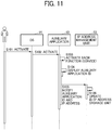
- FIG. 11 is a sequence diagram illustrating an example of an operation in which the first terminal 10 notifies the image management server 50 of the auxiliary application ID when the first terminal is started.
- the OS 14 In the first terminal 10, the OS 14 first starts operating. When the OS 14 starts operating, the OS 14 automatically causes the auxiliary application 13 to start operating. In another example, the OS 14 launches the auxiliary application 13 according to user operation.
- the auxiliary application 13 activates various functions (services) according to instructions from the OS 14.
- the ID display unit 33 acquires the auxiliary application ID 35a stored in the storage unit 35 and displays the auxiliary application ID on a screen (display 3).
- the ID notification unit 32 transmits the auxiliary application ID to the image management server 50 via the communication unit 31. With this process, the image management server 50 acquires an IP address of the first terminal 10.
- the first communication unit 51 of the image management server 50 acquires the auxiliary application ID and the IP address of the first terminal 10. Further, the IP address management unit 53 stores the auxiliary application ID and the IP address of the first terminal 10 in association with each other in the ID/IP address storage unit 56.
- the auxiliary application ID and the IP address of the first terminal 10 are automatically stored in the image management server 50.
- the first terminal 10 is not associated with a specific electronic canvas. Accordingly, each time the second terminal 30 transmits the auxiliary application ID, a screen of the first terminal 10 is transmitted to the second terminal 30.
- the ID notification unit 32 requests the image management server 50 to delete the auxiliary application ID and the IP address of the first terminal 10.
- FIG. 12 is a sequence diagram illustrating an example of an operation in which the second terminal 30 generates electronic canvas.
- a user of the second terminal 30 operates the second terminal 30 to enter an URL of the image management server 50 to the second terminal 30.
- the user knows the URL in advance.
- the operation receiving unit 24 receives the URL of the image management server 50.
- the electronic canvas is generated at a specific URL so that one or more second terminals 30 can access the electronic canvas.
- One URL is associated with one electronic canvas.
- different URLs are assigned to different electronic canvases, respectively.
- the following is an example of the URL of the electronic canvas. http://server/kaigi/k001
- the second communication unit 52 of the image management server 50 transmits the URL of the electronic canvas to the second terminal 30.
- S205 The communication unit 22 of the second terminal 30 receives the URL of the electronic canvas and accesses (connects) this URL.
- any second terminal 30 can display the same electronic canvas by accessing the URL of the electronic canvas.
- the communication unit 22 of the second terminal 30 transmits a notification indicating the change to the canvas screen generator 55 via the second communication unit 52.
- the canvas screen generator 55 updates the screen information.
- the canvas screen generator 55 sends a notification indicating that there was a change to one or more other second terminals 30.
- the second terminal 30 periodically accesses the URL of the electronic canvas to update the electronic canvas.
- FIG. 13 is a sequence diagram illustrating an example of an operation in which the first terminal 10 captures a screen and the second terminal 30 displays image data of a screen of the material display application 11.
- the display control unit 21 In response to the pressing of the capture button 407, the display control unit 21 displays the auxiliary application ID field 420 as a pop-up menu.
- S403 The user confirms the auxiliary application ID 35a displayed on the display3 by the first terminal 10, and enters the auxiliary application ID in the auxiliary application ID field 420.
- the operation receiving unit 24 receives the auxiliary application ID.
- the communication unit 22 of the second terminal 30 transmits a capture request including the auxiliary application ID to the image management server 50.
- the transmission destination is the URL of the electronic canvas.
- the display control unit 21 displays a message such as "Capture in progress" until receiving image data of a screen of the material display application 11.
- the IP address management unit 53 acquires an IP address that is associated with the auxiliary application ID from the ID/IP address storage unit 56. The IP address is sent to the canvas screen generator 55. Thus, the first terminal 10 is identified.
- the canvas screen generator 55 sends the capture request together with the IP address of the first terminal 10 to the image acquisition unit 54.
- the image acquisition unit 54 assigns a unique capture number and sends the capture number and the capture request to the first terminal 10 identified by the IP address via the first communication unit 51 of the image management server 50.
- the capture number is identification information for identifying the electronic canvas to which image data of a screen is to be sent back. For this reason, the image acquisition unit 54 associates the URL of the electronic canvas with the capture number. This enables the image acquisition unit 54 to send image data of a screen to the electronic canvas to which the second terminal 30 that sent the capture request is connecting, even in a case where a plurality of electronic canvases are generated.
- the communication unit 31 of the first terminal 10 receives the capture request, and the screen capturing unit 34 requests the OS 14 to capture a screen.
- the screen capturing unit 34 acquires image data of the screen (document displayed by the material display application 11).
- the screen capturing unit 34 compresses the image data of the screen. This enables to reduce the size of the image data. In a case where the size of the image data is small, compression can be omitted.
- the communication unit 31 of the first terminal 10 transmits the image data of the screen and the capture number to the image management server 50.
- the first communication unit 51 of the image management server 50 receives the image data of the screen. Further, the image acquisition unit 54 stores the image data of the screen in the storage device of the image management server 50. The image acquisition unit 54 uses the capture number to identify the electronic canvas (canvas screen generator 55) that requested the image data of the screen, and sends the image data of the screen to the identified canvas screen generator 55.
- the image acquisition unit 54 uses the capture number to identify the electronic canvas (canvas screen generator 55) that requested the image data of the screen, and sends the image data of the screen to the identified canvas screen generator 55.
- the canvas screen generator 55 adds the image data of the screen to the screen information of the electronic canvas to update the screen information.
- the screen information already generated by the canvas screen generator 55 is updated using the image data of the screen.
- the canvas screen generator 55 performs the process of adding the image data of the screen to the screen information of the electronic canvas identified by the URL or the like to which the capture request is sent in step S404.
- the screen information of the screen on which the capture button 407 was displayed in step S401 is updated.
- the screen information corresponding to the URL of step S205 in FIG. 12 is updated, which corresponds to the screen on which the capture button 407 was displayed in step S401.
- the canvas screen generator 55 of the image management server 50 sends a notification indicating the update of the electronic canvas to the browser application 15 (communication unit 22) of the second terminal 30 via the second communication unit 52.
- the display control unit 21 sends a request for the screen information of the updated electronic canvas to the URL of the electronic canvas via the communication unit 22.
- the display control unit 21 displays the screen of the material display application 11 displayed by the first terminal 10.
- auxiliary application ID is entered manually by a user every time.
- manual entry by each time can be omitted by configuring a setting in advance, since the auxiliary application ID seldom changes.
- the first terminal 10 can display two or more material display applications 11.
- the auxiliary applications 13 as many as the material display applications 11 are activated.
- the second terminal 30 can display a desired screen among the screens displayed by the plurality of material display applications 11.
- the first terminal 10 and the second terminal 30 connect to the image management server 50 and thereby the second terminal 30 acquires a screen being displayed by the first terminal 10. Further, the second terminal 30 can acquire a screen being displayed by the first terminal 10, without necessity of installing a special application in the second terminal. A user can share the screen being displayed by the first terminal 10 by entering the auxiliary application ID.
- the information sharing system according to the present embodiment since an electronic canvas is generated in response to a user's instruction, the association between the electronic canvas and the first terminal 10 is not fixed. Accordingly, the user can cause the electronic canvas to display a screen of a desired first terminal 10 by entering the auxiliary application ID. In other word, since screens of the different first terminals 10 can be displayed on the electronic canvas, the electronic canvas can be used like a memo of the user.
- second terminal 30 does not receive an instruction from first terminal 10, a user of second terminal 30 is not able to decide a screen in which the user desires from all screens displayed in a conference (or meeting or the like). Even if second terminal 30 is able acquire a screen from first terminal 10, the user would have to look for the screen which the user desires from all screens displayed in the conference. In accordance with the present application, however, the user can confirm only the screen required by the user at any time, because second terminal 30 requests the screen when receiving an instruction to do so from the user. Also, since second terminal 30 displays only the screens which are acquired when receiving an instruction from the user, second terminal 30 is able to display only the screens desired by the use at any time.
- second terminal 30 receives a plurality of instructions, second terminal 30 displays a plurality of corresponding screens.
- an apparatus in accordance with the present application improves a user's experience by allowing the user to confirm and view desired screens during a conference (or meeting or the like).
- a screen is captured in response to a capture request from the image management server 50 to the first terminal 10.
- the first terminal 10 captures a screen periodically or in response to detection of a change of the screen and uploads image data of the screen to the image management server 50.
- the image acquisition unit 54 stores the image data of the screen in association with the IP address of the first terminal 10. Further, in response to a request from the second terminal 30, the image acquisition unit 54 transmits the latest one of the stored image data of the screen.
- the first terminal 10 generates an electronic canvas. Since the first terminal 10 generates an electronic canvas, the first terminal 10 and an electronic canvas are associated with each other at the time of startup of the first terminal 10. On the other hand, a user of the second terminal 30 does not know to which URL the user should instruct the second terminal to connect to use the electronic canvas generated by the first terminal 10. For this reason, the first terminal 10 displays an URL of the generated electronic canvas. The user enters this URL to the second terminal 30 to specify the electronic canvas generated by the first terminal 10. This enables the second terminal 30 to acquire mage data of a screen of the material display application 11.
- FIG. 14 is a block diagram illustrating an example of a functional configuration of each of the first terminal 10, the second terminal 30, and the image management server 50, according to the present embodiment. In the following description of FIG. 14 , the differences from FIG. 6 are focused.
- the auxiliary application 13 includes the communication unit 31, an electronic canvas generation requesting unit 36, a URL display unit 37, and the screen capturing unit 34.
- the auxiliary application 13 additionally includes the electronic canvas generation requesting unit 36 and the URL display unit 37.
- the electronic canvas generation requesting unit 36 requests the image management server 50 to generate an electronic canvas, for example, at the time of startup of the first terminal 10 or according to an operation by a user.
- the electronic canvas generation requesting unit 36 acquires an URL of the generated electronic canvas from the image management server 50. Further, the electronic canvas generation requesting unit 36 stores the URL 35b of the electronic canvas in the storage unit 35.
- the URL display unit 37 causes the display 3 to display the URL 35b of the electronic canvas.
- the image management server 50 includes a URL/IP address storage unit 57 instead of the ID/IP address storage unit 56 of the first embodiment.
- functions implemented by the canvas screen generator 55 are different from those of the first embodiment.
- the canvas screen generator 55 according to the present embodiment stores the URL of the electronic canvas generated in response to the request from the first terminal 10 and the IP address of the first terminal 10 in the URL/IP address storage unit 57 in association with each other.
- Table 2 is an example of information stored in the URL/IP address storage unit 57.
- URLs of the electronic canvases and IP addresses of the first terminals 10 are registered in association with each other. This enables the image management server 50 to identify the IP address of the first terminal 10 based on the URL of the electronic canvas.
- FIG. 15 is an illustration for describing an example of an overview of generation of an electronic canvas, according to the present embodiment.
- the image management server 50 receives the electronic canvas generation request, and generates an electronic canvas at an URL generated by a generation process determined in advance.
- the image management server 50 registers the URL of the electronic canvas and the IP address of the first terminal 10 in the URL/IP address storage unit 57 in association with each other.
- the image management server 50 transmits the URL of the electronic canvas to the first terminal 10.
- the first terminal 10 stores the URL in the storage unit 35. Further, the auxiliary application 13 causes the display 3 to display the URL of the electronic canvas.
- a user of the second terminal 30 can causes the second terminal 30 to access the electronic canvas and display the screen of the material display application 11.
- FIG. 16 is an illustration for describing an example of an overview of screen capturing according to the present embodiment.
- S50 First, the user enters the URL of the electronic canvas displayed by the first terminal 10 into the second terminal 30. As a result, firstly, an electronic canvas in the initial state (or an electronic canvas on which another user draws characters or figures by hand or to which image data of the screen is added) is displayed on the second terminal 30.
- the communication unit 22 of the second terminal 30 transmits a capture request to the URL of the electronic canvas.
- the first communication unit 51 of the image management server 50 transmits the capture request to the first terminal 10 identified by the IP address.
- the communication unit 31 of the first terminal 10 receives the capture request, and the screen capturing unit 34 requests the OS 14 to capture a screen.
- the screen capturing unit 34 generates image data of the screen (document displayed by the material display application 11).
- the communication unit 31 of the first terminal 10 transmits the image data of the screen to the image management server 50.
- the first communication unit 51 of the image management server 50 receives the image data of the screen, and the canvas screen generator 55 performs an update of adding the image data to the screen information of the electronic canvas.
- the second communication unit 52 of the image management server 50 transmits a notification indicating the update of the electronic canvas.
- the communication unit 22 of the second terminal 30 requests the updated screen information of the electronic canvas. Accordingly, the electronic canvas application 12 can display the screen of the material display application 11 being displayed by the first terminal 10.
- FIG. 17 is a sequence diagram illustrating an example of an operation in which the first terminal 10 registers an URL of an electronic canvas and an IP address of the first terminal 10 in association with each other when the first terminal is activated.
- the OS 14 In the first terminal 10, the OS 14 first starts operating. When the OS 14 starts operating, the OS 14 automatically causes the auxiliary application 13 to start operating. In another example, the user launches the auxiliary application 13.
- the auxiliary application 13 activates various functions (services) according to instructions from the OS 14.
- the electronic canvas generation requesting unit 36 transmits, to the image management server 50, an electronic canvas generation request together with the IP address of the first terminal 10.
- the first communication unit 51 of the image management server 50 receives the electronic canvas generation request, and the canvas screen generator 55 generates a new electronic canvas in association with an URL. It is preferable that this URL does not overlap any URL generated in the past. In another example, since an electronic canvas is wide, the URL can be the same as any URL generated in the past.
- the canvas screen generator 55 registers the URL of the electronic canvas and the IP address of the first terminal 10 in association with each other in the URL/IP address storage unit 57.
- the first communication unit 51 of the image management server 50 transmits the URL of the electronic canvas to the auxiliary application 13 of the first terminal 10.
- the communication unit 31 of the first terminal 10 receives the URL of the electronic canvas, and the electronic canvas generation requesting unit 36 causes the storage unit 35 to store the URL 35b of the electronic canvas.
- the URL display unit 37 causes the display 3 to display the URL 35b of the electronic canvas.
- the first terminal 10 when the first terminal 10 is started, the first terminal 10 automatically generates the electronic canvas and displays the URL of the electronic canvas. This enables a user to connect to the electronic canvas by entering this URL.
- the URL of the electronic canvas and the first terminal 10 are associated with each other. Accordingly, when this URL is specified, the second terminal 30 can share the screen of the first terminal 10.
- the electronic canvas generation requesting unit 36 requests the image management server 50 to delete the URL of the electronic canvas and the IP address of the first terminal 10.
- FIG. 18 is a sequence diagram illustrating an example of an operation in which the first terminal 10 captures a screen and the second terminal 30 displays image data of a screen of the material display application 11. In the following description of FIG. 18 , the differences from FIG. 13 are focused.
- S601 A user who wants to cause the second terminal 30 to display a screen of the first terminal 10 using an electronic canvas generated by the first terminal 10 enters the URL 35b of the electronic canvas being displayed by the first terminal 10 to the second terminal 30.
- S602 The communication unit 22 of the second terminal 30 connects to the URL 35b of the electronic canvas. As a result, screen information of the electronic canvas is transmitted to the second terminal 30. The second terminal 30 executes the screen information, and thereby the electronic canvas application 12 starts operating.
- the communication unit 22 of the second terminal 30 transmits a capture request to the image management server 50 while specifying the URL of the electronic canvas.
- the display control unit 21 displays a message such as "Capture in progress" until receiving image data of a screen of the material display application 11.
- the canvas screen generator 55 sends the capture request together with the IP address of the first terminal 10 to the image acquisition unit 54.
- the subsequent steps can be the same as the steps S408 to S416 of FIG. 13 .
- the first terminal 10 In a case where the first terminal 10 generates the electronic canvas as described, it is required to specify the electronic canvas in order to acquire the screen of the material display application 11. In the present embodiment, the first terminal 10 displays the URL of the electronic canvas. This enables the second terminal 30 to access the electronic canvas.
- the first terminal 10 and the second terminal 30 connect to the image management server 50 and thereby the second terminal 30 acquires a screen being displayed by the first terminal 10.
- a user can share the screen being displayed by the first terminal 10 by entering an URL of an electronic canvas.
- the first terminal 10 generates an electronic canvas. Accordingly, the relation between the electronic canvas and the first terminal 10 is fixed, users who want to display the screen of the first terminal 10 on the second terminal 30 uses the same electronic canvas. Therefore, each user can write information on the same electronic canvas. For example, this enables plural users to write contents that are discussed while viewing a large screen of the first terminal 10 on the electronic canvas and share the electronic canvas to which the discussed contents are added.
- the first terminal 10 can capture a screen periodically or in response to detection of a change of the screen and upload image data of the screen to the image management server 50 in advance.
- the second terminal 30 can continuously display a preview of a screen of the first terminal 10.
- the second terminal 30 copies image data of the previewed screen to the electronic canvas and displays the copied image data.
- FIG. 19 is an example illustration for describing capturing in a case where the second terminal 30 displays a preview. According to the screen capture procedure of either the first or the second embodiment, the second terminal 30 continuously displays a preview 430 of image data of the screen. An overview of the operation is provided hereinafter.
- a screen of the electronic canvas is divided into, for example, the preview area 431 and a handwriting area 432.
- the capture button 407 When a user presses the capture button 407, the image data in the preview area 431 is copied and displayed in the handwriting area 432. Since the second terminal 30 transmits the copied image data to the image management server 50, the screen information in the image management server 50 is also updated.
- FIG. 20 is a sequence diagram illustrating an example of an operation in which the first terminal 10 captures a screen and the second terminal 30 displays image data of a screen of the material display application 11. In the following description of FIG. 20 , the differences from FIG. 13 are focused.
- S401-2 When a user wants to cause the second terminal 30 to display a preview of a screen of the first terminal 10, the user presses a preview button displayed in the menu 401, for example.
- the operation receiving unit 24 receives the pressing of the preview button.
- the electronic canvas application 12 starts displaying the preview without the user's operation for displaying the preview.
- step S402 to step S407 can be the same as those of FIG. 13 .
- the image management server 50 periodically repeats the processes from step S408 to step S413-2.
- the image management server 50 monitors the load to perform the processes when the load is low.
- the image management server 50 performs the processes irregularly.
- step S413-2 the canvas screen generator 55 updates the preview area 431 in the screen information to the latest image data of the screen. Subsequent steps from S414 can be the same as those of FIG. 13 .
- sequence diagram can be substantially the same as that of the first embodiment.
- sequence diagram of the first embodiment is taken as an example, the operation can be performed in substantially the same manner using the sequence diagram of the second embodiment. With this method, it is possible to shorten the waiting time of a user until image data of the screen is displayed.
- the operation illustrated in the sequence diagram of FIG. 13 or FIG. 18 may be performed in response to the pressing of the capture button 407 to cause the second terminal 30 to acquire the image data. Since image quality of the preview 430 is sometimes deteriorated due to compression or the like, the second terminal 30 acquires the image data again, so that deterioration in image quality of the image data displayed by the electronic canvas can be suppressed.
- the second terminal 30 displays a preview of the screen of the first terminal 10 even if a user does not press the capture button 407. This enables the user to determine whether to capture after viewing the preview on the second terminal 30.
- FIG. 21 is a diagram illustrating a layer structure of a screen displayed by the second terminal 30.
- FIG. 22 to FIG. 29 are diagrams each illustrating an example of screen displayed by the second terminal 30.
- the second terminal 30 displays a screen having a four-layer structure.
- the lowermost layer is a ground layer (electronic canvas layer or SVG (scalable vector graphics) drawing layer).
- a layer provided on the ground layer is a view port layer (tool palette layer).
- a layer provided on the view port layer is a screen sharing layer (moving picture streaming layer).
- a layer provided on the screen sharing layer is a modal dialog layer of the browser.
- the display control unit 21 performs display processing, and the operation receiving unit 24 receives operations of a mouse, an electronic pen, or the like.
- the display control unit 21 of the second terminal 30 displays a ground area 500 on the display 3.
- a view port area 510, a screen sharing area 520, and a scaling specifying area 530 are included.
- the view port area 510 includes a screen shift button 511 having the same function as the screen shift button 404, a pen button 513 having the same function as the pen button 402, etc.
- the screen sharing area 520 includes a sharing area 521, a capture button 522, a transmission/reception switching button 523, a reduction button 524, and an enlargement button 525.
- the sharing area 521 is an area for displaying a shared screen information.
- the capture button 522 has the same function as the capture button 407.
- the transmission/reception switching button 523 is a button for switching between reception and transmission of image data of the screen.
- the reduction button 524 is a button for reducing the screen sharing area 520 having a normal size.
- the enlargement button 525 is a button for enlarging the screen sharing area 520.
- the scaling specifying area 530 is an area in which a scrollbar for changing the size of the ground area 500 is displayed.
- an image "A" of a screen being displayed on the first terminal 10 is displayed in the sharing area 521, which is provided at the lower right of the ground area 500.
- image data of the image "A” is shared between the first terminal 10 and the second terminal 30.
- a captured-image display area 501a including the image "A” is displayed at the left center of the ground area 500, as illustrated in FIG. 23 .
- a character input area 501b in which characters can be entered is displayed on the right side of the captured-image display area 501a.
- a caret c2 is initially displayed in the character input area 501b, allowing the user to promptly enter comments.
- the cursor c1 is displayed over the capture button 522, allowing the user to promptly instruct capturing subsequently.
- a captured-image display area 502a including the image "B” is displayed at the left center of the ground area 500, as illustrated in FIG. 24 .
- a character input area 502b in which characters can be entered is displayed on the right side of the captured-image display area 502a.
- the image captured once before moves to the upper left of the ground area 500 so that the captured-image display area 502a is displayed in the left middle area of the ground area 500.
- a caret c2 is initially displayed in the character input area 502b, and the cursor c1 is displayed over the capture button 522.
- a screen shift mode starts operating.
- a scroll icon s1 for scrolling the ground area 500 is displayed.
- FIG. 25 illustrates an example case where the entire image is shifted to the right side compared with FIG. 24 .
- the position of the screen sharing area 520 does not change.
- FIG. 27 illustrates a state in which the character input area 502b is currently being moved to the left after moving the captured-image display area 502a to the right.
- the latest captured-image display area 502A and the latest character input area 502B are displayed with a larger size than the captured-image display area 501a and the captured-image display area 502a.
- the sharing area 521 is displayed on an upper layer (front) of the captured-image display area 502A and the character input area 502B.
- the sharing area 521 is not displayed, as illustrated in FIG. 29 .
- the display density of the reduction button 524 becomes light, and the button is invalidated. This indicates that the sharing area 521 cannot be reduced any more.
- an image of the captured screen is displayed with a character input area that allows a user to promptly enter a comment. This enables a user to enter comments speedily.
- the electronic canvas application 12 can be provided not only as a web application but also as an application that does not require a browser application.
- a user of the second terminal 30 is present in the same space where the first terminal 10 is provided, the user of the second terminal 30 does not have to be present in the same space where the first terminal 10 is provided.
- the auxiliary application ID or the URL of the electronic canvas is notified to users outside a company by e-mail or the like so that the users outside the company can share the screen.
- processes performed by the first terminal 10, the second terminal 30 and the image management server 50 are divided based on main functions in order to facilitate understanding of processes. No limitation is intended by how the processes are divided or by the name of the processes.
- the processes implemented by the first terminal 10, the second terminal 30 and the image management server 50 can be divided to a larger number of processes according to contents of processes. Further, one process can be divided to include a larger number of processes.
- the second communication unit 52 is an example of acquisition request receiving means.
- the image acquisition unit 54 is an example of image acquiring means.
- the canvas screen generator 55 is an example of screen information updating means.
- the communication unit 22 is an example of receiving means.
- the display control unit 21 is an example of display control means.
- the ID/IP address storage unit 56 is an example of first association information storing means.
- the URL/IP address storage unit 57 is an example of second association information storing means.
- the IP address management unit 53 is an example of address information acquiring means.
- the material display application 11 is an example of a first application.
- the auxiliary application 13 is an example of a second application.
- the present invention can be implemented in any convenient form, for example using dedicated hardware, or a mixture of dedicated hardware and software.
- the present invention may be implemented as computer software implemented by one or more networked processing apparatuses.
- the processing apparatuses can compromise any suitably programmed apparatuses such as a general purpose computer, personal digital assistant, mobile telephone (such as a WAP or 3G-compliant phone) and so on. Since the present invention can be implemented as software, each and every aspect of the present invention thus encompasses computer software implementable on a programmable device.
- the computer software can be provided to the programmable device using any conventional carrier medium (carrier means).
- the carrier medium can compromise a transient carrier medium such as an electrical, optical, microwave, acoustic or radio frequency signal carrying the computer code.
- transient medium is a TCP/IP signal carrying computer code over an IP network, such as the Internet.
- the carrier medium can also comprise a storage medium for storing processor readable code such as a floppy disk, hard disk, CD ROM, magnetic tape device or solid state memory device.
Landscapes
- Engineering & Computer Science (AREA)
- Theoretical Computer Science (AREA)
- Signal Processing (AREA)
- Computer Networks & Wireless Communication (AREA)
- General Engineering & Computer Science (AREA)
- General Physics & Mathematics (AREA)
- Physics & Mathematics (AREA)
- Human Computer Interaction (AREA)
- Databases & Information Systems (AREA)
- Multimedia (AREA)
- Data Mining & Analysis (AREA)
- Information Transfer Between Computers (AREA)
- User Interface Of Digital Computer (AREA)
- Controls And Circuits For Display Device (AREA)
Abstract
Description
- The present invention relates to an information management apparatus, an information sharing system, and a method of sharing information.
- At gatherings such as conferences, meetings, and presentations, where plural participants gather for a certain purpose, presentation materials are displayed on a first terminal having a large screen, for example. The first terminal displays the materials on the large screen, and the participants discuss based on the materials or give explanation about the materials. In this case, the materials are displayed not only on the large screen of the first terminal, but also on a second terminal that each participant brings with himself or herself. Each participant attends the meeting or the like while viewing the materials displayed on his or her own terminal.
- Therefore, each participant needs to obtain the materials. Conventionally, each participant receives the materials sent by e-mail or accesses a specific URL (uniform resource locator) to download the material. A technique is also known in which a first terminal displays materials together with information indicating how to specify the materials and a participant who needs the materials acquires the materials based on the information indicating how to specify the material. For example, an information processing system is known that projects a QR (quick response) code including information identifying a file being projected. According to the information processing system, a second terminal of an arbitrary participant reads the displayed QR code to download the file being projected.
- However, according to the method disclosed in
JP-2014-199657-A - An object of the present invention is to provide an information management apparatus that enables a second terminal to display a screen displayed by a first terminal.
- In one aspect of the present invention, an information management apparatus (50) is communicable with a first terminal (10) and a second terminal (30) via a network. The first terminal (10) is configured to control a first display output a first screen shareable by a plurality of users, the second terminal (30) operated by a user of the plurality of users and the second terminal configured to control a second display to output a second screen to be viewed by the user, the information management apparatus (50) comprising:
- acquisition request receiving means (52) for receiving, from the second terminal (30) a screen acquisition request that requests acquisition of the first screen output by the first terminal (10);
- image acquiring means (54) for transmitting, in response to the screen acquisition request received by the acquisition request receiving means (52), a request for image data to the first terminal (10) and acquiring image data of the first screen from the first terminal (10); and
- screen information updating means (55) for updating screen information to be transmitted to the second terminal (30) according to the image data of the first screen acquired by the image acquiring means (54).
- According to an aspect of the present invention, an information management apparatus is provided that is configured to allow a second terminal to display a screen displayed by a first terminal.
- A more complete appreciation of the embodiments and many of the attendant advantages and features thereof can be readily obtained and understood from the following detailed description with reference to the accompanying drawings, wherein:
-
FIG. 1 is an illustration for describing an overview of a procedure in which a second terminal displays a screen being displayed by a first terminal having a large screen, according an embodiment of the present invention; -
FIG. 2 is a schematic diagram illustrating an example of a configuration of an information sharing system, according an embodiment of the present invention; -
FIG. 3 is a block diagram illustrating an example of a hardware configuration of each of the first terminal and the second terminal, according an embodiment of the present invention; -
FIG. 4 is a block diagram illustrating an example of a hardware configuration of an image management server, according an embodiment of the present invention; -
FIG. 5A is a block diagram illustrating an example of a configuration of software operating on the first terminal, according an embodiment of the present invention; -
FIG. 5B is a block diagram illustrating an example of a configuration of software operating on the second terminal, according an embodiment of the present invention; -
FIG. 6 is a block diagram illustrating an example of a functional configuration of each of the first terminal, the second terminal, and the image management server, according to an embodiment of the present invention; -
FIG. 7 is a diagram illustrating an example of an auxiliary application ID displayed on a display by the first terminal, according to an embodiment of the present invention; -
FIG. 8 is a diagram illustrating an example of a menu and an information display bar displayed by an electronic canvas application of the second terminal, according to an embodiment of the present invention; -
FIG. 9 is an illustration for describing an example of an overview of generation of an electronic canvas, according to an embodiment of the present invention; -
FIG. 10 is an illustration for describing an example of an overview of screen capturing, according to an embodiment of the present invention; -
FIG. 11 is a sequence diagram illustrating an example of an operation in which the first terminal notifies the image management server of the auxiliary application ID when the first terminal is started, according to an embodiment of the present invention; -
FIG. 12 is a sequence diagram illustrating an example of an operation in which the second terminal generates electronic canvas, according to an embodiment of the present invention; -
FIG. 13 is a sequence diagram illustrating an example of an operation in which the first terminal captures a screen and the second terminal displays image data of a screen of a material display application, according to an embodiment of the present invention; -
FIG. 14 is a block diagram illustrating an example of a functional configuration of each of the first terminal, the second terminal, and the image management server, according to an embodiment of the present invention; -
FIG. 15 is an illustration for describing an example of an overview of generation of an electronic canvas, according to an embodiment of the present invention; -
FIG. 16 is an illustration for describing an example of an overview of screen capturing, according to an embodiment of the present invention; -
FIG. 17 is a sequence diagram illustrating an example of an operation in which the first terminal registers an URL of the electronic canvas and an IP address of the first terminal in association with each other when the first terminal is started, according to an embodiment of the present invention; -
FIG. 18 is a sequence diagram illustrating an example of an operation in which the first terminal captures a screen and the second terminal displays image data of a screen of a material display application, according to an embodiment of the present invention; -
FIG. 19 is an example illustration for describing capturing in a case where the second terminal displays a preview, according to an embodiment of the present invention; -
FIG. 20 is a sequence diagram illustrating an example of an operation in which the first terminal captures a screen and the second terminal displays image data of a screen of the material display application, according to an embodiment of the present invention; -
FIG. 21 is a diagram illustrating a layer structure of a screen displayed by the second terminal, according to an embodiment of the present invention; -
FIG. 22 is a diagram illustrating an example of a screen of the second terminal, according to an embodiment of the present invention; -
FIG. 23 is a diagram illustrating an example of a screen of the second terminal, according to an embodiment of the present invention; -
FIG. 24 is a diagram illustrating an example of a screen of the second terminal, according to an embodiment of the present invention; -
FIG. 25 is a diagram illustrating an example of a screen of the second terminal, according to an embodiment of the present invention; -
FIG. 26 is a diagram illustrating an example of a screen of the second terminal, according to an embodiment of the present invention; -
FIG. 27 is a diagram illustrating an example of a screen of the second terminal, according to an embodiment of the present invention; -
FIG. 28 is a diagram illustrating an example of a screen of the second terminal, according to an embodiment of the present invention, and -
FIG. 29 is a diagram illustrating an example of a screen of the second terminal, according to an embodiment of the present invention. - The accompanying drawings are intended to depict embodiments of the present invention and should not be interpreted to limit the scope thereof. The accompanying drawings are not to be considered as drawn to scale unless explicitly noted.
- In describing embodiments illustrated in the drawings, specific terminology is employed for the sake of clarity. However, the disclosure of this specification is not intended to be limited to the specific terminology so selected and it is to be understood that each specific element includes all technical equivalents that have a similar function, operate in a similar manner, and achieve a similar result.
- As used herein, the singular forms "a", "an", and "the" are intended to include the multiple forms as well, unless the context clearly indicates otherwise.
- A description is given of example embodiments of an information sharing system and a method of sharing information performed by the information sharing system with reference to the drawings.
- First, with reference to
FIG. 1 , an overview of an operation by an information sharing system according to the present embodiment is described.FIG. 1 is an illustration for describing an overview of a procedure in which asecond terminal 30 displays a screen being displayed by afirst terminal 10 having a large screen. Thefirst terminal 10 is a computer that a plurality of users can jointly use or share and whose screen is viewed by the plurality of users. Such afirst terminal 10 may be referred to as a "shared terminal". Thesecond terminal 30 is a computer that a user can use individually or exclusively and whose screen is viewed by the user individually. Such asecond terminal 30 may be referred to as a "privately-owned terminal", butsecond terminal 30 is not limited to being privately-owned.Second terminal 30 may be public, private, non-profit, rental or any other type of ownership terminal in which a user may individually or exclusively use the terminal and whose screen is viewed by the user individually. - First, as a premise, in the
first terminal 10, amaterial display application 11 displays a content (image) of presentation material. Further, in thefirst terminal 10, anauxiliary application 13 for capturing a screen operates. In thesecond terminal 30, abrowser application 15 operates. - (1) The
first terminal 10 connects to theimage management server 50 at the time of activation or the like. Theimage management server 50 is an example of an information management device apparatus. Thesecond terminal 30 connects to a predetermined URL of theimage management server 50 through operations of the first and second embodiments described later. This URL is a URL that allows thesecond terminal 30 to share a screen with thefirst terminal 10. - (2) A user of the
second terminal 30 who wants to own a screen displayed by thefirst terminal 10 presses a predetermined button. - (3) In response to pressing of the specific button by the user, the
second terminal 30 transmits a capture request to theimage management server 50. This capture request is an example of a screen acquisition request. - (4) The
image management server 50 transmits the capture request to thefirst terminal 10 while specifying an IP address of thefirst terminal 10, which is acquired when thefirst terminal 10 connects to theimage management server 50. The IP address is one of address information of the first terminal. - (5) In response to acquiring the capture request, the
auxiliary application 13 captures the screen being displayed on a screen by thematerial display application 11. - (6) The
auxiliary application 13 of thefirst terminal 10 transmits image data of the screen to theimage management server 50. - (7) The
image management server 50 adds the image data to screen information (web page) to be transmitted to thebrowser application 15. - (8) The
browser application 15 of thesecond terminal 30 acquires the screen information including the image data of the screen from theimage management server 50. - (9) Thus, the
second terminal 30 displays the screen being displayed by thefirst terminal 10 on a display. - As described above, according the information sharing system of the present embodiment, the
first terminal 10 and thesecond terminal 30 connect to theimage management server 50 and thereby thesecond terminal 30 displays a screen being displayed by thefirst terminal 10. - In the embodiments, a "display device" is a device that displays an image. The display device is sometimes referred to as a "display". In alternative to the general-purpose display such as a liquid crystal display, the display device can be a projector.
- An "electronic canvas application" is a program. An "electronic canvas" is a function implemented by an electronic canvas application or a screen displayed by the electronic canvas application. In this disclosure, the "electronic canvas" is not a plain-woven thick cloth but a virtual canvas generated in the
image management server 50. For example, a web application having a function of allowing a user to write handwritten information or a function of displaying an image with the canvas element and JavaScript (registered trademark) or the like corresponds to the electronic canvas. For descriptive purposes, in this disclosure, the electronic canvas application and the electronic canvas may not be distinguished clearly from each other. - Acquisition of a screen refers to capturing a screen or generating image data of a screen. In one example, an entire screen is captured. In another example, the image data of the screen is divided a part of the image data of the screen is cut out, to capture a part of the image. The acquisition of the screen is referred to as "trimming" or "capture" in some cases.
-
FIG. 2 is a schematic diagram illustrating an example of a configuration of the information sharing system, according to the present embodiment. The information sharing system includes thefirst terminal 10, thesecond terminal 30, and theimage management server 50, which are communicable with each other via a network N. AlthoughFIG. 2 illustrates an example in which the information sharing system includes onefirst terminal 10 and onesecond terminal 30, in another example, the information sharing system can include two or morefirst terminals 10 and two or moresecond terminals 30. - The
first terminal 10 and thesecond terminal 30 are described in different names because they have different roles in the present embodiment. However, each of thefirst terminal 10 and thesecond terminal 30 can be an information processing apparatus of the same type.FIG. 1 illustrates an example in which a display of thefirst terminal 10 displaying information is depicted larger than a display of thesecond terminal 30. In another example, the displays of thefirst terminal 10 and thesecond terminal 30 have the same size. In still another example, the display of thesecond terminal 30 is larger than the display of thefirst terminal 10. In other words, a device that displays information and performs capturing is thefirst terminal 10. - It is preferable that each of the
first terminal 10 and thesecond terminal 30 includes a touch panel. However, in the present embodiment, the touch panel is optional. When thesecond terminal 30 includes a touch panel, there is an advantage that a user can write characters or draw a picture with his or her finger, an electronic pen or the like on an image displayed based on image data acquired from thefirst terminal 10. The handwriting function can be substituted by a mouse or a trackball. - The
first terminal 10 is a general-purpose information processing apparatus. Examples of thefirst terminal 10 include, but not limited to, a tablet terminal, a smartphone, a laptop computer, and a personal digital assistant (PDA). Thefirst terminal 10 is any device on which a desiredmaterial display application 11 and theauxiliary application 13 operate. In another example, thefirst terminal 10 is an electronic whiteboard (or an electronic board, an information board, etc.) that displays handwritten information or a screen acquired from a personal computer (PC). In still another example, thefirst terminal 10 is a device that projects an image such as a projector. In still another example, thefirst terminal 10 is a device that displays images of plural sites such as a videoconference terminal. In still another example thefirst terminal 10 is a television receiver. - Like the
first terminal 10, examples of thesecond terminal 30 include a tablet terminal, a smartphone, a laptop computer, and a PDA. Thesecond terminal 30 is any device on which a browser application operates. For example, the first terminal is a multifunction peripheral, a car navigation device, a game machine, a television receiver, or the like. - The
image management server 50 is one or more information processing apparatuses having a function as a web server (or an HTTP server) that transmits screen information to thesecond terminal 30. The screen information is provided as a web page generated by a web application. The "web application" refers to software that operates by cooperation between a program described in a script language such as JavaScript (registered trademark) operating on a browser application and a program on the web server side, which operate in cooperation with each other, and is used on the browser or such mechanism. - The
image management server 50 provides thesecond terminal 30 with a web application by which thesecond terminal 30 is used like the electronic canvas. In the present embodiment, this web application is referred to as an electronic canvas application. Thesecond terminal 30 can use the electronic canvas application, provided that thebrowser application 15 operates on thesecond terminal 30. - In one example, the
image management server 50 supports cloud computing. The "cloud computing" refers to computing where resources on a network are used or accessed without identifying specific hardware resources. - The network N is, for example, one or more local area networks (LANs) inside the firewall. In another example, the network N includes the Internet that is outside the firewall in addition to the LAN. In another example, the network N further includes a virtual private network (VPN) and/or a wide-area Ethernet (registered trademark). The network N is any one of a wired network, a wireless network, and a combination of the wired network and the wireless network. In a case where the
first terminal 10, thesecond terminal 30 or theimage management server 50 connects to the network N through a mobile phone network such as 3G, Long Term Evolution (LTE), 4G, the LAN can be omitted. - With reference to
FIG. 3 , a description is given of hardware configurations of thefirst terminal 10 and thesecond terminal 30, according to the present embodiment.FIG. 3 is a block diagram illustrating an example of a hardware configuration of each of thefirst terminal 10 and thesecond terminal 30. In the following description ofFIG. 3 , it is assumed that each of thefirst terminal 10 and thesecond terminal 30 is a general-purpose information processing apparatus. - As illustrated in
FIG. 3 , each of thefirst terminal 10 and thesecond terminal 30 includes a central processing unit (CPU) 101, a read only memory (ROM) 102, a random access memory (RAM) 103, a solid state drive (SSD) 104, anetwork controller 105, and anexternal memory controller 106. TheCPU 101 controls entire operation of each of thefirst terminal 10 and thesecond terminal 30. TheROM 102 stores a control program for controlling theCPU 101 such as an initial program loader (IPL). TheRAM 103 is used as a work area for theCPU 101. TheSSD 104 stores various data including a program for each of thefirst terminal 10 and thesecond terminal 30. Thenetwork controller 105 controls communication with an external device through the network N. Theexternal memory controller 106 controls communication between each of thefirst terminal 10 and thesecond terminal 30 and a universal serial bus (USB)memory 5. -
CPU 101 may include modules, parts, circuits, processing circuitry and/or integrated circuits, all of which may be referred to as processing circuitry. The processing circuitry may include a general-purpose processor, and the processing circuitry may include any number of processors, controllers, micro-controllers or state machines. Processing circuitry includes a programmed processor, as a processor includes circuitry. A processing circuit also includes devices such as an application specific integrated circuit (ASIC), digital signal processor (DSP), field programmable gate array (FPGA), and conventional circuit components arranged to perform functions. - Each of the
first terminal 10 and thesecond terminal 30 further includes a graphics processing unit (GPU)112 and adisplay controller 113. TheGPU 112 is dedicated to processing a graphical image. Thedisplay controller 113 controls display of an image processed at theGPU 112 for output through adisplay 3.GPU 112 may include modules, parts, circuits, processing circuitry and/or integrated circuits, all of which may be referred to as processing circuitry. Moreover,GPU 112 may include processing circuitry that is separate from the processing circuitry ofCPU 101. Alternatively,GPU 112 andCPU 101 may be encompassed by the same processing circuitry. - Further, each of the
first terminal 10 and thesecond terminal 30 includes asensor controller 114 and acontact sensor 115. Thesensor controller 114 controls operation of thecontact sensor 115. Thecontact sensor 115 detects a touch onto thedisplay 3 with anelectronic pen 4 or a user's hand. For example, thecontact sensor 115 detects a coordinate of a position touched by the user based on a change of capacitance (implements a touch panel). Thecontact sensor 115 can identify a contact position in various manners in addition to by detecting change of capacitance. For example, a resistance film touch panel can be used that identifies a contact position by detecting a change in voltage of two opposed resistance films. In another example, an electromagnetic induction touch panel that identifies a contact position by detecting electromagnetic induction caused by contact of an object to a display. - Each of the
first terminal 10 and thesecond terminal 30 further includes abus line 120, such as an address bus or a data bus, which electrically connects theCPU 101, theROM 102, theRAM 103, theSSD 104, thenetwork controller 105, theexternal memory controller 106, theGPU 112, and thesensor controller 114 to each other. - The program for each of the
first terminal 10 and thesecond terminal 30 is stored on a computer-readable storage medium such as a compact disc read only memory (CD-ROM) for distribution, for example. In another example, the program is distributed from a server for program distribution. -
FIG. 4 is a block diagram illustrating an example of a hardware configuration of theimage management server 50. Theimage management server 50 includes aCPU 201 and amemory 202 that enables high-speed access to data by theCPU 201. TheCPU 201 and thememory 202 are connected to other hardware elements of theimage management server 50, such as agraphics driver 204 and a network driver (NIC) 205, via asystem bus 203. -
CPU 201 may include modules, parts, circuits, processing circuitry and/or integrated circuits, all of which may be referred to as processing circuitry. The processing circuitry may include a general-purpose processor, and the processing circuitry may include any number of processors, controllers, micro-controllers or state machines. Processing circuitry includes a programmed processor, as a processor includes circuitry. A processing circuit also includes devices such as an application specific integrated circuit (ASIC), digital signal processor (DSP), field programmable gate array (FPGA), and conventional circuit components arranged to perform functions. - The
graphics driver 204 is connected to a liquid crystal display (LCD) 206 via a bus, and monitors a result of processing by theCPU 201. Further, thenetwork driver 205 connects theimage management server 50 to the network N at a transport layer level and a physical layer level to establish a session with thefirst terminal 10 and thesecond terminal 30. - Further, an input/output (I/O)
bus bridge 207 is connected to thesystem bus 203. On the downstream side of the I/O bus bridge 207, a storage device such as a hard disc drive (HDD) 209 is connected via an I/O bus 208 such as a peripheral component interconnect (PCI), in compliance with the Integrated Drive Electronics (IDE), Advanced Technology Attachment (ATA), AT Attachment Packet Interface (ATAPI), serial ATA, Small Computer System Interface (SCSI), USB, etc. TheHDD 209 stores aprogram 209p for controlling entire operation of theimage management server 50. TheHDD 209 is replaceable with an SSD. - Further, an
input device 210 such as a keyboard and a mouse (also referred to as a pointing device) is connected to the I/O bus 208 via a bus such as a USB. Theinput device 210 receives inputs or instructions from an operator such as a system administrator. - The illustrated hardware configuration of the
image management server 50 is not necessarily housed in one housing nor provided as apparatus of one unit. The illustrated hardware configuration indicates hardware elements preferably included in theimage management server 50. In addition, in order to support cloud computing, a physical configuration of theimage management server 50 of the present embodiment is not necessarily fixed. In other words, theimage management server 50 is configured as hardware resources that dynamically connect/disconnect according to load. - Next, with reference to
FIG. 5A and FIG. 5B , a description is given of a software configuration of thefirst terminal 10 and thesecond terminal 30.FIG. 5A is a block diagram illustrating an example of a configuration of software operating on thefirst terminal 10. An operating system (OS) 14 operates on thefirst terminal 10. Thematerial display application 11 and theauxiliary application 13 operates on theOS 14. - Examples of the
OS 14 include, but not limited to, Android (registered trademark), iOS (registered trademark), Windows (registered trademark), UNIX (registered trademark), LINUX (registered trademark), and macOS (registered trademark). The OS can vary depending on the model of thefirst terminal 10. - The
material display application 11 is an application for displaying materials of a meeting, for example. The materials displayed by thematerial display application 11 are shared by users. Since it depends on a user's attributes or circumstances as to what is used as the material, thematerial display application 11 can be any application that operates on theOS 14 and displays some kinds of screen. For example, at a conference, a presentation application is used as thematerial display application 11. In addition, a browser application for displaying information on the Internet, a word processing application for editing or displaying a document, a spreadsheet application, and the like can also be used as thematerial display application 11. Further, a photograph application for displaying photographs, a game application such as a local game and an online game, a painting application that allows a user to draw a picture, a file management application, and the like can also be used as thematerial display application 11. The above described applications are examples of thematerial display application 11 and any other suitable application can be used as thematerial display application 11. - The
auxiliary application 13 provides an auxiliary function that enables thesecond terminal 30 to display an image based on image data of a screen generated by thematerial display application 11. For example, theauxiliary application 13 performs communication with theimage management server 50 or invokes an API (application interface) of theOS 14 to capture the screen generated by thematerial display application 11. Theauxiliary application 13 reduces restrictions on thematerial display application 11. Accordingly, a user can use a general-purpose application as thematerial display application 11. Since thematerial display application 11 does not require any special function, a desired application can be used as thematerial display application 11. Theauxiliary application 13 needs to have a function of receiving a request from the electronic canvas application via theimage management server 50. Therefore, theauxiliary application 13 and theelectronic canvas application 12 operate in cooperation with each other via theimage management server 50. - Since the
auxiliary application 13 acquires image data of a screen generated by thematerial display application 11 by using functions of theOS 14, theauxiliary application 13 deals with functions that are heavily dependent on a model of thefirst terminal 10. For this reason, theauxiliary application 13 is a native application. A term "native application" is used in comparison with a web application. The "native application" refers to an application that is installed in thefirst terminal 10 for execution. The native application is an application that uses functions of theOS 14 and controls hardware. - Since the
auxiliary application 13 according to the present embodiment operates inside thefirst terminal 10, theauxiliary application 13 does not have to display a screen in principle. However, in some cases, theauxiliary application 13 displays an auxiliary application ID and a URL of the electronic canvas as described later. -
FIG. 5B is a block diagram illustrating an example of a configuration of software operating on thesecond terminal 30. AnOS 16 operates on thesecond terminal 30. Theelectronic canvas application 12 operates on theOS 16. TheOS 14 of thefirst terminal 10 and theOS 16 of thesecond terminal 30 do not need be the same type. - The
browser application 15 acquires a script that is to operate on thebrowser application 15 from theimage management server 50 by specifying an URL of the electronic canvas and executes the acquired script to implement theelectronic canvas application 12. Theelectronic canvas application 12 is a web application that provides a user with a function of the electronic canvas. As described above, theelectronic canvas application 12 includes a function of displaying an image based on the image data of a screen generated by thematerial display application 11 and a function of displaying handwritten information. In a case where thebrowser application 15 has a function of displaying an image based on the image data of the screen generated by thematerial display application 11, theelectronic canvas application 12 does not have to include the function of the electronic canvas (does not have to include a handwriting function). In another example, theelectronic canvas application 12 merely acquires image data from theimage management server 50 and displays an image based on the acquired image data. In this case, the script is not necessarily required, and theelectronic canvas application 12 having a function of acquiring, from theimage management server 50, information including the image data of the screen generated by thematerial display application 11 to be displayed by thebrowser application 15 will suffice. Therefore, thebrowser application 15 does not have to execute a script. Further, an application having a function equivalent to that of thebrowser application 15 will suffice. - Since the
electronic canvas application 12 is executed on thebrowser application 15, dependence on a model of thesecond terminal 30 is low. Since theelectronic canvas application 12 is a web application and operates by executing a script transmitted from theimage management server 50, installation is unnecessary. On the other hand, it is often difficult for the web application to utilize functions of theOS 16 or to control hardware. - In the present embodiment, a description is given of an example in which an electronic canvas is generated by the
second terminal 30 and image data of a screen displayed by thefirst terminal 10 is displayed on the electronic canvas. Since the generated electronic canvas is not associated with thefirst terminal 10, a user of thesecond terminal 30 needs to inform theimage management server 50 of whichfirst terminal 10 the user is viewing. For this reason, theauxiliary application 13 that is resident in thefirst terminal 10 displays an auxiliary application ID. Thesecond terminal 30 transmits this auxiliary application ID to theimage management server 50 in accordance with the user's operation. Theimage management server 50 identifies thefirst terminal 10 based on the auxiliary application ID and adds a screen being displayed by thefirst terminal 10 to screen information of the electronic canvas generated by thesecond terminal 30. - Functions of the
electronic canvas application 12, theauxiliary application 13, and theimage management server 50 are described with reference toFIG. 6. FIG. 6 is a block diagram illustrating an example of a functional configuration of each of thefirst terminal 10, thesecond terminal 30, and theimage management server 50. Since thematerial display application 11 will suffice, provided that it includes a function of displaying a screen, functions of thematerial display application 11 are described as needed. - The
electronic canvas application 12 includes adisplay control unit 21, acommunication unit 22, astroke generator 23, and anoperation receiving unit 24. Thedisplay control unit 21, thecommunication unit 22, thestroke generator 23, and theoperation receiving unit 24 of thesecond terminal 30 are functions or means that are implemented by or that are caused to function by operating any of the elements illustrated inFIG. 3 in cooperation with instructions of theCPU 101 according to the program loaded from theSSD 104 onto theRAM 103 and the script transmitted from theimage management server 50. - The
communication unit 22 transmits and receives various information to and from theimage management server 50. For example, thecommunication unit 22 receives screen information described in HTML, CSS (Cascade Style Sheet), and JavaScript (registered trademark) from theimage management server 50. Further, thecommunication unit 22 transmits handwritten information that is input by handwriting by a user to theimage management server 50. - The
operation receiving unit 24 receives various operations by the user input to theelectronic canvas application 12. For example, theoperation receiving unit 24 receives pressing of a button displayed on a menu or handwritten information input to the touch panel. - The
stroke generator 23 generates a stroke based on the handwritten information input to the touch panel received by theoperation receiving unit 24. Since the handwritten information received by theoperation receiving unit 24 is a list of coordinates of points, plural points are merely displayed if the handwritten information is displayed as is. For this reason, thestroke generator 23 generates a stroke by linking the points with color, thickness, a line type or the like specified by the user. - The
display control unit 21 analyzes the screen information received by thecommunication unit 22 and displays a web page on a display device (thedisplay 3 or the LCD 206). Further, thedisplay control unit 21 displays the stroke generated by thestroke generator 23 on the display device. - The
auxiliary application 13 includes acommunication unit 31, anID notification unit 32, anID display unit 33, and ascreen capturing unit 34. Thecommunication unit 31, theID notification unit 32, theID display unit 33, and thescreen capturing unit 34 of thefirst terminal 10 are functions or means that are implemented by or that are caused to function by operating any of the elements illustrated inFIG. 3 in cooperation with instructions of theCPU 101 according to the program loaded from theSSD 104 onto theRAM 103. - Further, the
auxiliary application 13 includes astorage unit 35 implemented by theSSD 104, theRAM 103 or the like illustrated inFIG. 3 and stores theauxiliary application ID 35a in thestorage unit 35. - The
communication unit 31 transmits and receives various information to and from theimage management server 50. In the present embodiment, thecommunication unit 31 transmits the auxiliary application ID to theimage management server 50 and transmits image data of a screen to theimage management server 50. - The
ID notification unit 32 notifies theimage management server 50 of theauxiliary application ID 35a via thecommunication unit 31, in response to, for example, activation of thefirst terminal 10 or operation by the user. Theauxiliary application ID 35a is identification information for identifying or specifying theauxiliary application 13. In the present embodiment, theauxiliary application ID 35a is used as identification information for identifying or specifying thefirst terminal 10. Since the auxiliary application ID is set in theauxiliary application 13 before shipment from a factory, the auxiliary application ID is basically a fixed value. However, in an exceptional case, a user can change the auxiliary application ID. TheID notification unit 32 sends a request for changing the auxiliary application ID to theimage management server 50 via thecommunication unit 31. When theimage management server 50 confirms that the requested auxiliary application ID does not overlap with any other auxiliary application ID, the change is accepted. - The
ID display unit 33 displays the auxiliary application ID in at least a partial area of thedisplay 3 of thefirst terminal 10. A display surface of thedisplay 3 is referred to as a screen, and it can be said that the auxiliary application ID is displayed on the screen. For example, theID display unit 33 displays the auxiliary application ID on a transparent layer on a front side (a side closer to a user) of thefirst terminal 10. TheID display unit 33 displays the auxiliary application ID in one of four corners of the screen, for example, preferably as semi-transparent, so as not to hide information displayed by thematerial display application 11. The auxiliary application ID does not have to be constantly displayed. For example, theID display unit 33 periodically displays the auxiliary application ID. In another example, theID display unit 33 display the auxiliary application ID in response to a user's instruction for displaying the auxiliary application ID. - The
screen capturing unit 34 requests theOS 14 to capture the screen. In response to the request, theOS 14 transmits image data including at least materials being displayed by thematerial display application 11 to thescreen capturing unit 34. In the present embodiment, a description is provided on the assumption that thematerial display application 11 displays materials in an entire area of thedisplay 3. When material is displayed in a partial area of thedisplay 3, theOS 14 crops (trims) a material part in image data of an entire area of the display 3 (entire area of the screen) according to a display area generated by thematerial display application 11. - The
image management server 50 includes afirst communication unit 51, asecond communication unit 52, an IPaddress management unit 53, animage acquisition unit 54, and acanvas screen generator 55. Thefirst communication unit 51, thesecond communication unit 52, the IPaddress management unit 53, theimage acquisition unit 54, and thecanvas screen generator 55 of theimage management server 50 are functions or means that are implemented by or that are caused to function by operating any of the elements illustrated inFIG. 4 in cooperation with instructions of theCPU 201 according to the program loaded from theHDD 209 onto thememory 202. Further, theimage management server 50 has an ID/IPaddress storage unit 56 implemented by theHDD 209 and/or thememory 202 illustrated inFIG. 4 . - The
first communication unit 51 transmits and receives various information to and from thefirst terminal 10. For example, thefirst communication unit 51 receives the auxiliary application ID and image data of the screen from thefirst terminal 10, and transmits the capture request to thefirst terminal 10. - The
second communication unit 52 transmits and receives various information to and from thesecond terminal 30. For example, thesecond communication unit 52 transmits the screen information described in HTML, CSS, and JavaScript (registered trademark) to thesecond terminal 30. Further, thesecond communication unit 52 receives the handwritten information that is input by handwriting by a user from thesecond terminal 30. - The IP
address management unit 53 registers an IP address of thefirst terminal 10 and the auxiliary application ID in the ID/IPaddress storage unit 56 in association with each other. Since the IPaddress management unit 53 acquires the IP address of thefirst terminal 10 when the auxiliary application ID is notified, the IPaddress management unit 53 registers this IP address and the notified auxiliary application ID in the ID/IPaddress storage unit 56. - In response to receiving the capture request specifying the auxiliary application ID from the
second terminal 30 via thefirst communication unit 51, theimage acquisition unit 54 acquires, via the IPaddress management unit 53, the IP address of thefirst terminal 10 associated with the auxiliary application ID from the IPaddress management unit 53, and transmits the screen capture request to thefirst terminal 10 via thefirst communication unit 51. Further, theimage acquisition unit 54 transmits image data of thematerial display application 11 acquired from this first terminal 10 to thesecond terminal 30. - The
canvas screen generator 55 performs management of the electronic canvas. First, thecanvas screen generator 55 performs generation and deletion of an electronic canvas screen. For example, in response to a request for generation of a new electronic canvas from thesecond terminal 30, thecanvas screen generator 55 generates an electronic canvas. In order to simplify the description, assuming that one URL corresponds to one electronic canvas, thecanvas screen generator 55 assigns a new URL to an electronic canvas and generates screen information for the electronic canvas to generate the electronic canvas. - Further, in response to a request for deletion of the electronic canvas from the
second terminal 30, thecanvas screen generator 55 deletes the electronic canvas. - The
canvas screen generator 55 manages data for each electronic canvas. Since the data is data displayed on the electronic canvas, examples of the data include handwritten information, text memo, and image data. Contents and display positions of these handwritten information, text memo, image data or the like are managed for each electronic canvas. - Further, the
canvas screen generator 55 generates screen information using the data managed by thecanvas screen generator 55. For example, when a plurality of strokes are overlapped with each other, the plurality of strokes are combined into one object. This improves image quality against enlargement, reduction, rotation, etc. - One of HTML elements suitable for the electronic canvas is Canvas element. The Canvas element is used for drawing figures or the like by scripting with JavaScript (registered trademark). The
canvas screen generator 55 updates the screen information each time data such as handwriting is added. - When the screen information is updated, the
second communication unit 52 notifies each second terminal 30 (except for thesecond terminal 30 that has transmitted the handwritten information) indicated by the URL of the electronic canvas of the update. Since thesecond terminal 30 accesses the URL of the electronic canvas to acquire the screen information, the data displayed by theelectronic canvas application 12 is shared almost in real time. - As described, since one electronic canvas is shared by a plurality of
second terminals 30, the electronic canvas can be used in various gatherings such as conferences, meetings, and presentations.[Table 1] Auxiliary Application ID IP Address (First terminal) 0123 10.60.100.100 2345 10.60.101.101 - Table 1 is an example of information stored in the ID/IP
address storage unit 56. In the ID/IPaddress storage unit 56, the auxiliary application ID and the IP address of thefirst terminal 10 are registered in association with each other. This allows theimage management server 50 to identify the IP address of thefirst terminal 10 based on the auxiliary application ID. -
FIG. 7 is a diagram illustrating an example of the auxiliary application ID displayed on thedisplay 3 by thefirst terminal 10. InFIG. 7 , theauxiliary application ID 35a indicated by "0123" as an example is displayed at the lower left of thedisplay 3. A user of thesecond terminal 30 can enter theauxiliary application ID 35a to thesecond terminal 30 by looking at the displayed auxiliary application ID. - In another example, the auxiliary application ID is displayed as a two-dimensional code such as a bar code (one-dimensional code) or QR code (registered trademark). In still another example, instead of displaying the auxiliary application ID on the screen, the
first terminal 10 transmits the auxiliary application ID to thesecond terminal 30 by short-range radio such as NFC (Near Filed Communication) or Bluetooth (registered trademark). - In still another example, the display position of the auxiliary application ID is any one of the four corners of the
display 3. This reduces the possibility that characters or the like displayed by thematerial display application 11 overlap with the auxiliary application ID. It is preferable that the auxiliary application ID is displayed as semi-transparent so that both characters or the like displayed by thematerial display application 11 and the auxiliary application ID can be recognized even when they are overlapped with each other. -
FIG. 8 is a diagram illustrating an example of amenu 401 and aninformation display bar 450 displayed by theelectronic canvas application 12 of thesecond terminal 30. Themenu 401 includes apen button 402, aneraser button 403, ascreen shift button 404, an undobutton 405, aredo button 406, acapture button 407, acharacter memo button 408, a businessapplication linkage button 409, and asetting button 410. In the following, a description is given of each of these buttons. - The
pen button 402 is a button that allows a user to draw handwritten information (stroke). Theeraser button 403 is a button that allows a user to erase the handwritten information. Thescreen shift button 404 is a button for displaying an area that is not being displayed on the display 3 (theelectronic canvas application 12 can theoretically have infinite size) on thedisplay 3. The undobutton 405 is a button for cancelling an action content and returning to a state where the action has not been performed. Theredo button 406 is a button for redoing the action that a user has undone and returning to a state where the action has been performed. Thecapture button 407 is a button for capturing image data of a screen displayed by thematerial display application 11. Thecharacter memo button 408 is a button for displaying software key canvas and allowing a user to enter text. The businessapplication linkage button 409 is a button for calling a cloud service (a cloud service other than theimage management server 50 of the present embodiment) and/or sending the auxiliary application ID or an URL of the electronic canvas (meeting) by e-mail. Thesetting button 410 is a button for accepting various settings. - A user presses the
capture button 407 in themenu 401 to cause thefirst terminal 10 to capture image data of the screen of thematerial display application 11. Theinformation display bar 450 is an area for indicting a current display area of the electronic canvas using coordinates and displaying a scaling factor. The electronic canvas is generated as having scrollable wide area so that a user's thinking is not interrupted by screen switching or the like. Accordingly, theelectronic canvas application 12 displays the current display area to enable a user to recognize which part he or she is viewing. The coordinate value displayed in theinformation display bar 450 is, for example, coordinates of the upper left corner of the display range with respect to an entire area of the electronic canvas or coordinates of the center of the display area. - Next, a description is given of each of an overview of generation of an electronic canvas and an overview of capturing of a screen.
-
FIG. 9 is an illustration for describing an example of an overview of generation of an electronic canvas. - S1: A user of the
second terminal 30 causes thesecond terminal 30 to connect to an URL of theimage management server 50. The user enters the URL of theimage management server 50 obtained in advance. With this operation, thesecond terminal 30 displays a top page. - S2: On the top page, a
button 460 including a message such as "Do you want to create an electronic canvas?" is displayed, and the user presses thisbutton 460. When theoperation receiving unit 24 of thesecond terminal 30 receives the pressing of thebutton 460, thecommunication unit 22 transmits a request for generation of an electronic canvas to theimage management server 50. - S3: In response to receiving the electronic canvas generation request by the
second communication unit 52 of theimage management server 50, thecanvas screen generator 55 generates an electronic canvas. - S4: The
second communication unit 52 of theimage management server 50 transmits screen information of the electronic canvas to thesecond terminal 30. - S5: The
communication unit 22 of thesecond terminal 30 receives the screen information of the electronic canvas. When thesecond terminal 30 executes the screen information on thebrowser application 15, theelectronic canvas application 12 activates. In its initial state, the electronic canvas is a white screen on which themenu 401 and theinformation display bar 450 are displayed. - As described, the user can generate the electronic canvas by connecting the
second terminal 30 to theimage management server 50. -
FIG. 10 is an illustration for describing an example of an overview of screen capturing. - S11: A user who wants to cause the
second terminal 30 to display a screen of thefirst terminal 10 presses thecapture button 407 of themenu 401. Theoperation receiving unit 24 receives pressing of thecapture button 407. - S12: In response to pressing of the
capture button 407, thedisplay control unit 21 displays an auxiliaryapplication ID field 420 as a pop-up menu. The user confirms the auxiliary application ID displayed on thedisplay 3 by thefirst terminal 10 and enters the auxiliary application ID in the auxiliaryapplication ID field 420. Theoperation receiving unit 24 receives the auxiliary application ID. The user can specify thefirst terminal 10 by entering the auxiliary application ID. - S13: The
communication unit 22 of thesecond terminal 30 transmits a capture request including the auxiliary application ID to theimage management server 50. This capture request is transmitted based on the screen information generated by theimage management server 50. In other words, thecapture button 407 is generated by thecanvas screen generator 55 of theimage management server 50. - S14: When the
second communication unit 52 of theimage management server 50 receives the capture request, theimage acquisition unit 54 acquires an IP address associated with the auxiliary application ID via the IPaddress management unit 53. Thus, thefirst terminal 10 is identified. - S15: The
first communication unit 51 of theimage management server 50 transmits the capture request to thefirst terminal 10 identified by the IP address. - S16: The
communication unit 31 of thefirst terminal 10 receives the capture request, and thescreen capturing unit 34 requests theOS 14 to capture a screen, to generate image data of the screen. - S17: The
communication unit 31 of thefirst terminal 10 transmits the image data of the captured screen to theimage management server 50. - S18: The
first communication unit 51 of theimage management server 50 receives the image data of the screen, and thecanvas screen generator 55 performs an update of adding the image data to the screen information of the electronic canvas. - S19: The
second communication unit 52 of theimage management server 50 transmits a notification indicating the update of the electronic canvas. - S20: In response to receiving this update notification, the
communication unit 22 of the second terminal 30 requests the updated screen information of the electronic canvas. With this operation, theelectronic canvas application 12 of thesecond terminal 30 displays the same screen as the screen of thematerial display application 11 being displayed by thefirst terminal 10. - Next, with reference sequence diagrams, an operation flow performed when starting the
first terminal 10, an operation flow of generating an electronic canvas, and an operation flow of capturing a screen are described. - Operation Flow Performed When First terminal 10 is Started:
FIG. 11 is a sequence diagram illustrating an example of an operation in which thefirst terminal 10 notifies theimage management server 50 of the auxiliary application ID when the first terminal is started. - S101: When a user wants to use the
first terminal 10, the user starts thefirst terminal 10. For example, the user turns on the power. - S102: In the
first terminal 10, theOS 14 first starts operating. When theOS 14 starts operating, theOS 14 automatically causes theauxiliary application 13 to start operating. In another example, theOS 14 launches theauxiliary application 13 according to user operation. - S103: The
auxiliary application 13 activates various functions (services) according to instructions from theOS 14. - S104: First, the
ID display unit 33 acquires theauxiliary application ID 35a stored in thestorage unit 35 and displays the auxiliary application ID on a screen (display 3). - S105: Next, the
ID notification unit 32 transmits the auxiliary application ID to theimage management server 50 via thecommunication unit 31. With this process, theimage management server 50 acquires an IP address of thefirst terminal 10. - S106: The
first communication unit 51 of theimage management server 50 acquires the auxiliary application ID and the IP address of thefirst terminal 10. Further, the IPaddress management unit 53 stores the auxiliary application ID and the IP address of thefirst terminal 10 in association with each other in the ID/IPaddress storage unit 56. - As described, when the
first terminal 10 is started, the auxiliary application ID and the IP address of thefirst terminal 10 are automatically stored in theimage management server 50. In the present embodiment, thefirst terminal 10 is not associated with a specific electronic canvas. Accordingly, each time thesecond terminal 30 transmits the auxiliary application ID, a screen of thefirst terminal 10 is transmitted to thesecond terminal 30. In one example, when the power of thefirst terminal 10 is turned off, theID notification unit 32 requests theimage management server 50 to delete the auxiliary application ID and the IP address of thefirst terminal 10. -
FIG. 12 is a sequence diagram illustrating an example of an operation in which thesecond terminal 30 generates electronic canvas. - S201: A user of the
second terminal 30 operates thesecond terminal 30 to enter an URL of theimage management server 50 to thesecond terminal 30. The user knows the URL in advance. Theoperation receiving unit 24 receives the URL of theimage management server 50. - S202: When the
operation receiving unit 24 receives the user's operation of pressing thebutton 460 illustrated inFIG. 9 , thecommunication unit 22 of thesecond terminal 30 transmits a request for generation of an electronic canvas to theimage management server 50. - S203: In response to receiving this electronic canvas generation request by the
second communication unit 52 of theimage management server 50, thecanvas screen generator 55 generates an electronic canvas (screen information). - The electronic canvas is generated at a specific URL so that one or more
second terminals 30 can access the electronic canvas. One URL is associated with one electronic canvas. In other words, different URLs are assigned to different electronic canvases, respectively. The following is an example of the URL of the electronic canvas.
http://server/kaigi/k001 - S204: The
second communication unit 52 of theimage management server 50 transmits the URL of the electronic canvas to thesecond terminal 30. - S205: The
communication unit 22 of thesecond terminal 30 receives the URL of the electronic canvas and accesses (connects) this URL. - S206: When the
communication unit 22 of thesecond terminal 30 accesses the URL of the electronic canvas, thesecond communication unit 52 of theimage management server 50 transmits the screen information of the electronic canvas generated by thecanvas screen generator 55 to thesecond terminal 30. Thecommunication unit 22 of thesecond terminal 30 receives the screen information of the electronic canvas. - S207: When the
second terminal 30 executes display processing of the screen information on thebrowser application 15, theelectronic canvas application 12 starts operating, and thedisplay control unit 21 displays the electronic canvas on thedisplay 3. In its initial state, the electronic canvas is a white screen on which themenu 401 and theinformation display bar 450 are displayed. - Since one URL corresponds to one electronic canvas, any
second terminal 30 can display the same electronic canvas by accessing the URL of the electronic canvas. When data such has handwriting is written on the electronic canvas of thesecond terminal 30, thecommunication unit 22 of thesecond terminal 30 transmits a notification indicating the change to thecanvas screen generator 55 via thesecond communication unit 52. In response to receiving this notification, thecanvas screen generator 55 updates the screen information. Thecanvas screen generator 55 sends a notification indicating that there was a change to one or more othersecond terminals 30. In another example, thesecond terminal 30 periodically accesses the URL of the electronic canvas to update the electronic canvas. -
FIG. 13 is a sequence diagram illustrating an example of an operation in which thefirst terminal 10 captures a screen and thesecond terminal 30 displays image data of a screen of thematerial display application 11. - S401: When a user wants to cause the
second terminal 30 to display a screen of thefirst terminal 10, the user presses thecapture button 407 of themenu 401. Theoperation receiving unit 24 receives the pressing of thecapture button 407. - S402: In response to the pressing of the
capture button 407, thedisplay control unit 21 displays the auxiliaryapplication ID field 420 as a pop-up menu. - S403: The user confirms the
auxiliary application ID 35a displayed on the display3 by thefirst terminal 10, and enters the auxiliary application ID in the auxiliaryapplication ID field 420. Theoperation receiving unit 24 receives the auxiliary application ID. - S404: The
communication unit 22 of thesecond terminal 30 transmits a capture request including the auxiliary application ID to theimage management server 50. The transmission destination is the URL of the electronic canvas. In one example, thedisplay control unit 21 displays a message such as "Capture in progress" until receiving image data of a screen of thematerial display application 11. - S405: When the
second communication unit 52 of theimage management server 50 receives the capture request, thecanvas screen generator 55 sends the auxiliary application ID to the IPaddress management unit 53 to make an inquiry about the IP address of thefirst terminal 10. - S406: The IP
address management unit 53 acquires an IP address that is associated with the auxiliary application ID from the ID/IPaddress storage unit 56. The IP address is sent to thecanvas screen generator 55. Thus, thefirst terminal 10 is identified. - S407: The
canvas screen generator 55 sends the capture request together with the IP address of thefirst terminal 10 to theimage acquisition unit 54. - S408: The
image acquisition unit 54 assigns a unique capture number and sends the capture number and the capture request to thefirst terminal 10 identified by the IP address via thefirst communication unit 51 of theimage management server 50. The capture number is identification information for identifying the electronic canvas to which image data of a screen is to be sent back. For this reason, theimage acquisition unit 54 associates the URL of the electronic canvas with the capture number. This enables theimage acquisition unit 54 to send image data of a screen to the electronic canvas to which thesecond terminal 30 that sent the capture request is connecting, even in a case where a plurality of electronic canvases are generated. - S409: The
communication unit 31 of thefirst terminal 10 receives the capture request, and thescreen capturing unit 34 requests theOS 14 to capture a screen. Thus, thescreen capturing unit 34 acquires image data of the screen (document displayed by the material display application 11). - S410: The
screen capturing unit 34 compresses the image data of the screen. This enables to reduce the size of the image data. In a case where the size of the image data is small, compression can be omitted. - S411: The
communication unit 31 of thefirst terminal 10 transmits the image data of the screen and the capture number to theimage management server 50. - S412: The
first communication unit 51 of theimage management server 50 receives the image data of the screen. Further, theimage acquisition unit 54 stores the image data of the screen in the storage device of theimage management server 50. Theimage acquisition unit 54 uses the capture number to identify the electronic canvas (canvas screen generator 55) that requested the image data of the screen, and sends the image data of the screen to the identifiedcanvas screen generator 55. - S413: Next, the
canvas screen generator 55 adds the image data of the screen to the screen information of the electronic canvas to update the screen information. In other words, the screen information already generated by thecanvas screen generator 55 is updated using the image data of the screen. Thecanvas screen generator 55 performs the process of adding the image data of the screen to the screen information of the electronic canvas identified by the URL or the like to which the capture request is sent in step S404. Thus, the screen information of the screen on which thecapture button 407 was displayed in step S401 is updated. In other words, the screen information corresponding to the URL of step S205 inFIG. 12 is updated, which corresponds to the screen on which thecapture button 407 was displayed in step S401. - S414: In response to the update of the screen information, the
canvas screen generator 55 of theimage management server 50 sends a notification indicating the update of the electronic canvas to the browser application 15 (communication unit 22) of thesecond terminal 30 via thesecond communication unit 52. - S415: In response to receiving the update notification, the
communication unit 22 of thesecond terminal 30 instructs thedisplay control unit 21 to update the electronic canvas. - S416: The
display control unit 21 sends a request for the screen information of the updated electronic canvas to the URL of the electronic canvas via thecommunication unit 22. Thus, thedisplay control unit 21 displays the screen of thematerial display application 11 displayed by thefirst terminal 10. - With reference to the sequence diagram of
FIG. 13 , the above description is given assuming that the auxiliary application ID is entered manually by a user every time. In another example, such manual entry by each time can be omitted by configuring a setting in advance, since the auxiliary application ID seldom changes. - Further, the
first terminal 10 can display two or morematerial display applications 11. In this case, theauxiliary applications 13 as many as thematerial display applications 11 are activated. When a user enters the auxiliary application ID to thesecond terminal 30, thesecond terminal 30 can display a desired screen among the screens displayed by the plurality ofmaterial display applications 11. - As described above, according the information sharing system of the present embodiment, the
first terminal 10 and thesecond terminal 30 connect to theimage management server 50 and thereby thesecond terminal 30 acquires a screen being displayed by thefirst terminal 10. Further, thesecond terminal 30 can acquire a screen being displayed by thefirst terminal 10, without necessity of installing a special application in the second terminal. A user can share the screen being displayed by thefirst terminal 10 by entering the auxiliary application ID. In the information sharing system according to the present embodiment, since an electronic canvas is generated in response to a user's instruction, the association between the electronic canvas and thefirst terminal 10 is not fixed. Accordingly, the user can cause the electronic canvas to display a screen of a desiredfirst terminal 10 by entering the auxiliary application ID. In other word, since screens of the differentfirst terminals 10 can be displayed on the electronic canvas, the electronic canvas can be used like a memo of the user. - If
second terminal 30 does not receive an instruction fromfirst terminal 10, a user ofsecond terminal 30 is not able to decide a screen in which the user desires from all screens displayed in a conference (or meeting or the like). Even ifsecond terminal 30 is able acquire a screen fromfirst terminal 10, the user would have to look for the screen which the user desires from all screens displayed in the conference. In accordance with the present application, however, the user can confirm only the screen required by the user at any time, because second terminal 30 requests the screen when receiving an instruction to do so from the user. Also, since second terminal 30 displays only the screens which are acquired when receiving an instruction from the user,second terminal 30 is able to display only the screens desired by the use at any time. That is, ifsecond terminal 30 receives a plurality of instructions,second terminal 30 displays a plurality of corresponding screens. Thus, an apparatus in accordance with the present application improves a user's experience by allowing the user to confirm and view desired screens during a conference (or meeting or the like). - In the present embodiment, as described, a screen is captured in response to a capture request from the
image management server 50 to thefirst terminal 10. In another example, thefirst terminal 10 captures a screen periodically or in response to detection of a change of the screen and uploads image data of the screen to theimage management server 50. In this case, theimage acquisition unit 54 stores the image data of the screen in association with the IP address of thefirst terminal 10. Further, in response to a request from thesecond terminal 30, theimage acquisition unit 54 transmits the latest one of the stored image data of the screen. - In the present embodiment, a description is given of the information sharing system in which the
first terminal 10 generates an electronic canvas. Since thefirst terminal 10 generates an electronic canvas, thefirst terminal 10 and an electronic canvas are associated with each other at the time of startup of thefirst terminal 10. On the other hand, a user of thesecond terminal 30 does not know to which URL the user should instruct the second terminal to connect to use the electronic canvas generated by thefirst terminal 10. For this reason, thefirst terminal 10 displays an URL of the generated electronic canvas. The user enters this URL to thesecond terminal 30 to specify the electronic canvas generated by thefirst terminal 10. This enables thesecond terminal 30 to acquire mage data of a screen of thematerial display application 11. -
FIG. 14 is a block diagram illustrating an example of a functional configuration of each of thefirst terminal 10, thesecond terminal 30, and theimage management server 50, according to the present embodiment. In the following description ofFIG. 14 , the differences fromFIG. 6 are focused. - The
auxiliary application 13 includes thecommunication unit 31, an electronic canvasgeneration requesting unit 36, aURL display unit 37, and thescreen capturing unit 34. In other words, theauxiliary application 13 additionally includes the electronic canvasgeneration requesting unit 36 and theURL display unit 37. - The electronic canvas
generation requesting unit 36 requests theimage management server 50 to generate an electronic canvas, for example, at the time of startup of thefirst terminal 10 or according to an operation by a user. The electronic canvasgeneration requesting unit 36 acquires an URL of the generated electronic canvas from theimage management server 50. Further, the electronic canvasgeneration requesting unit 36 stores theURL 35b of the electronic canvas in thestorage unit 35. TheURL display unit 37 causes thedisplay 3 to display theURL 35b of the electronic canvas. - The
image management server 50 according to the present embodiment includes a URL/IPaddress storage unit 57 instead of the ID/IPaddress storage unit 56 of the first embodiment. In addition, functions implemented by thecanvas screen generator 55 are different from those of the first embodiment. Thecanvas screen generator 55 according to the present embodiment stores the URL of the electronic canvas generated in response to the request from thefirst terminal 10 and the IP address of thefirst terminal 10 in the URL/IPaddress storage unit 57 in association with each other.[Table 2] URL of Electronic Canvas IP Address (First terminal) http://server/kaigi/k001 10.60.100.100 http ://server/kaigi/k002 10.60.101.101 - Table 2 is an example of information stored in the URL/IP
address storage unit 57. In the URL/IPaddress storage unit 57, URLs of the electronic canvases and IP addresses of thefirst terminals 10 are registered in association with each other. This enables theimage management server 50 to identify the IP address of thefirst terminal 10 based on the URL of the electronic canvas. - Next, a description is given of each of an overview of generation of an electronic canvas and an overview of capturing of a screen.
-
FIG. 15 is an illustration for describing an example of an overview of generation of an electronic canvas, according to the present embodiment. - S41: The user turns on the power of the
first terminal 10. - S42: When the first terminal 10 starts operating, the
first terminal 10 transmits an electronic canvas generation request to theimage management server 50. In theauxiliary application 13, an URL of theimage management server 50 is set in advance. Together with the electronic canvas generation request, the IP address of thefirst terminal 10 is also transmitted. - S43: The
image management server 50 receives the electronic canvas generation request, and generates an electronic canvas at an URL generated by a generation process determined in advance. - S44: The
image management server 50 registers the URL of the electronic canvas and the IP address of thefirst terminal 10 in the URL/IPaddress storage unit 57 in association with each other. - S45: The
image management server 50 transmits the URL of the electronic canvas to thefirst terminal 10. - S46: In response to receiving the URL of the electronic canvas, the first terminal 10 stores the URL in the
storage unit 35. Further, theauxiliary application 13 causes thedisplay 3 to display the URL of the electronic canvas. - Since the URL is displayed in this manner, a user of the
second terminal 30 can causes thesecond terminal 30 to access the electronic canvas and display the screen of thematerial display application 11. -
FIG. 16 is an illustration for describing an example of an overview of screen capturing according to the present embodiment. - S50: First, the user enters the URL of the electronic canvas displayed by the
first terminal 10 into thesecond terminal 30. As a result, firstly, an electronic canvas in the initial state (or an electronic canvas on which another user draws characters or figures by hand or to which image data of the screen is added) is displayed on thesecond terminal 30. - S51: Next, when the user wants to cause the
second terminal 30 to display a screen of thefirst terminal 10, the user presses thecapture button 407 of themenu 401. Theoperation receiving unit 24 receives the pressing of thecapture button 407. Since the URL of the electronic canvas has been input, in the present embodiment, the auxiliaryapplication ID field 420 is not displayed. - S53: The
communication unit 22 of thesecond terminal 30 transmits a capture request to the URL of the electronic canvas. - S54: When the
second communication unit 52 of theimage management server 50 receives the capture request, thecanvas screen generator 55 acquires the IP address associated with the URL of the electronic canvas from the URL/IPaddress storage unit 57. Thus, thefirst terminal 10 is identified. - S55: The
first communication unit 51 of theimage management server 50 transmits the capture request to thefirst terminal 10 identified by the IP address. - S56: The
communication unit 31 of thefirst terminal 10 receives the capture request, and thescreen capturing unit 34 requests theOS 14 to capture a screen. Thus, thescreen capturing unit 34 generates image data of the screen (document displayed by the material display application 11). - S57: The
communication unit 31 of thefirst terminal 10 transmits the image data of the screen to theimage management server 50. - S58: The
first communication unit 51 of theimage management server 50 receives the image data of the screen, and thecanvas screen generator 55 performs an update of adding the image data to the screen information of the electronic canvas. - S59: The
second communication unit 52 of theimage management server 50 transmits a notification indicating the update of the electronic canvas. - S60: In response to receiving this update notification, the
communication unit 22 of the second terminal 30 requests the updated screen information of the electronic canvas. Accordingly, theelectronic canvas application 12 can display the screen of thematerial display application 11 being displayed by thefirst terminal 10. - Next, with reference sequence diagrams, an operation flow performed when starting the
first terminal 10, and an operation flow of capturing a screen are described. - Operation Flow Performed When First terminal 10 is Started
-
FIG. 17 is a sequence diagram illustrating an example of an operation in which thefirst terminal 10 registers an URL of an electronic canvas and an IP address of thefirst terminal 10 in association with each other when the first terminal is activated. - S501: When a user wants to use the
first terminal 10, the user starts thefirst terminal 10. For example, the user turns on the power. - S502: In the
first terminal 10, theOS 14 first starts operating. When theOS 14 starts operating, theOS 14 automatically causes theauxiliary application 13 to start operating. In another example, the user launches theauxiliary application 13. - S503: The
auxiliary application 13 activates various functions (services) according to instructions from theOS 14. - S504: First, the electronic canvas
generation requesting unit 36 transmits, to theimage management server 50, an electronic canvas generation request together with the IP address of thefirst terminal 10. - S505: The
first communication unit 51 of theimage management server 50 receives the electronic canvas generation request, and thecanvas screen generator 55 generates a new electronic canvas in association with an URL. It is preferable that this URL does not overlap any URL generated in the past. In another example, since an electronic canvas is wide, the URL can be the same as any URL generated in the past. - S506: The
canvas screen generator 55 registers the URL of the electronic canvas and the IP address of thefirst terminal 10 in association with each other in the URL/IPaddress storage unit 57. - S507: The
first communication unit 51 of theimage management server 50 transmits the URL of the electronic canvas to theauxiliary application 13 of thefirst terminal 10. - S508: The
communication unit 31 of thefirst terminal 10 receives the URL of the electronic canvas, and the electronic canvasgeneration requesting unit 36 causes thestorage unit 35 to store theURL 35b of the electronic canvas. TheURL display unit 37 causes thedisplay 3 to display theURL 35b of the electronic canvas. - As described with reference to the sequence diagram of
FIG. 17 , when thefirst terminal 10 is started, thefirst terminal 10 automatically generates the electronic canvas and displays the URL of the electronic canvas. This enables a user to connect to the electronic canvas by entering this URL. In the present embodiment, when the first terminal 10 starts operating, the URL of the electronic canvas and thefirst terminal 10 are associated with each other. Accordingly, when this URL is specified, thesecond terminal 30 can share the screen of thefirst terminal 10. In one example, when the power of thefirst terminal 10 is turned off, the electronic canvasgeneration requesting unit 36 requests theimage management server 50 to delete the URL of the electronic canvas and the IP address of thefirst terminal 10. -
FIG. 18 is a sequence diagram illustrating an example of an operation in which thefirst terminal 10 captures a screen and thesecond terminal 30 displays image data of a screen of thematerial display application 11. In the following description ofFIG. 18 , the differences fromFIG. 13 are focused. - S601: A user who wants to cause the
second terminal 30 to display a screen of thefirst terminal 10 using an electronic canvas generated by thefirst terminal 10 enters theURL 35b of the electronic canvas being displayed by thefirst terminal 10 to thesecond terminal 30. - S602: The
communication unit 22 of thesecond terminal 30 connects to theURL 35b of the electronic canvas. As a result, screen information of the electronic canvas is transmitted to thesecond terminal 30. Thesecond terminal 30 executes the screen information, and thereby theelectronic canvas application 12 starts operating. - S603: Next, in order to cause the
electronic canvas application 12 to display the screen of thefirst terminal 10, the user presses thecapture button 407 of themenu 401. Theoperation receiving unit 24 receives the pressing of thecapture button 407. - S604: The
communication unit 22 of thesecond terminal 30 transmits a capture request to theimage management server 50 while specifying the URL of the electronic canvas. In one example, thedisplay control unit 21 displays a message such as "Capture in progress" until receiving image data of a screen of thematerial display application 11. - S605: When the
second communication unit 52 of theimage management server 50 receives the capture request, thecanvas screen generator 55 acquires the IP address of thefirst terminal 10 associated with the URL of the electronic canvas from the URL/IPaddress storage unit 57. - S607: The
canvas screen generator 55 sends the capture request together with the IP address of thefirst terminal 10 to theimage acquisition unit 54. The subsequent steps can be the same as the steps S408 to S416 ofFIG. 13 . - In a case where the
first terminal 10 generates the electronic canvas as described, it is required to specify the electronic canvas in order to acquire the screen of thematerial display application 11. In the present embodiment, thefirst terminal 10 displays the URL of the electronic canvas. This enables thesecond terminal 30 to access the electronic canvas. - As described above, according the information sharing system of the present embodiment, the
first terminal 10 and thesecond terminal 30 connect to theimage management server 50 and thereby thesecond terminal 30 acquires a screen being displayed by thefirst terminal 10. A user can share the screen being displayed by thefirst terminal 10 by entering an URL of an electronic canvas. In the information sharing system according to the present embodiment, thefirst terminal 10 generates an electronic canvas. Accordingly, the relation between the electronic canvas and thefirst terminal 10 is fixed, users who want to display the screen of thefirst terminal 10 on thesecond terminal 30 uses the same electronic canvas. Therefore, each user can write information on the same electronic canvas. For example, this enables plural users to write contents that are discussed while viewing a large screen of thefirst terminal 10 on the electronic canvas and share the electronic canvas to which the discussed contents are added. - As described in the first embodiment, also in the present embodiment, the
first terminal 10 can capture a screen periodically or in response to detection of a change of the screen and upload image data of the screen to theimage management server 50 in advance. - In any of the first and second embodiments, the
second terminal 30 can continuously display a preview of a screen of thefirst terminal 10. When the user presses thecapture button 407, the second terminal 30 copies image data of the previewed screen to the electronic canvas and displays the copied image data. -
FIG. 19 is an example illustration for describing capturing in a case where thesecond terminal 30 displays a preview. According to the screen capture procedure of either the first or the second embodiment, thesecond terminal 30 continuously displays apreview 430 of image data of the screen. An overview of the operation is provided hereinafter. - (1) First, at the stage of displaying the
preview 430, thesecond terminal 30 does not have to send a capture request. However, in the method of the first embodiment, thesecond terminal 30 transmits the auxiliary application ID to theimage management server 50 at least once. In the method of the second embodiment, thesecond terminal 30 connects to the URL of the electronic canvas. - (2) The
image management server 50 periodically transmits a capture request to thefirst terminal 10. Even in a case where no periodic capture request is transmitted, thefirst terminal 10 can upload image data of the screen that is captured periodically or in response to detection of a change of the screen. - (3) The
first terminal 10 uploads image data of the screen to theimage management server 50. - (4) The
image management server 50 updates the preview 430 (image data of the screen of the first terminal 10) to be displayed in apreview area 431 of thesecond terminal 30 to the latest image data of the screen, in screen information of the electronic canvas. - (5) The
second terminal 30 periodically transmits a request for screen information to the URL of the electronic canvas. This enables thesecond terminal 30 to continuously display thepreview 430 of the screen of thefirst terminal 10. - In this case, a screen of the electronic canvas is divided into, for example, the
preview area 431 and ahandwriting area 432. When a user presses thecapture button 407, the image data in thepreview area 431 is copied and displayed in thehandwriting area 432. Since thesecond terminal 30 transmits the copied image data to theimage management server 50, the screen information in theimage management server 50 is also updated. -
FIG. 20 is a sequence diagram illustrating an example of an operation in which thefirst terminal 10 captures a screen and thesecond terminal 30 displays image data of a screen of thematerial display application 11. In the following description ofFIG. 20 , the differences fromFIG. 13 are focused. - S401-2: When a user wants to cause the
second terminal 30 to display a preview of a screen of thefirst terminal 10, the user presses a preview button displayed in themenu 401, for example. Theoperation receiving unit 24 receives the pressing of the preview button. In another example, theelectronic canvas application 12 starts displaying the preview without the user's operation for displaying the preview. - The processes from step S402 to step S407 can be the same as those of
FIG. 13 . Further, theimage management server 50 periodically repeats the processes from step S408 to step S413-2. In another example, theimage management server 50 monitors the load to perform the processes when the load is low. In still another example, theimage management server 50 performs the processes irregularly. In step S413-2, thecanvas screen generator 55 updates thepreview area 431 in the screen information to the latest image data of the screen. Subsequent steps from S414 can be the same as those ofFIG. 13 . - In other words, the sequence diagram can be substantially the same as that of the first embodiment. In addition, although in
FIG. 20 , the sequence diagram of the first embodiment is taken as an example, the operation can be performed in substantially the same manner using the sequence diagram of the second embodiment. With this method, it is possible to shorten the waiting time of a user until image data of the screen is displayed. - In the above, a description is given of an example in which the image data in the
preview area 431 is copied when the user actually presses thecapture button 407. In another example, the operation illustrated in the sequence diagram ofFIG. 13 orFIG. 18 may be performed in response to the pressing of thecapture button 407 to cause thesecond terminal 30 to acquire the image data. Since image quality of thepreview 430 is sometimes deteriorated due to compression or the like, thesecond terminal 30 acquires the image data again, so that deterioration in image quality of the image data displayed by the electronic canvas can be suppressed. - According to the present embodiment, the
second terminal 30 displays a preview of the screen of thefirst terminal 10 even if a user does not press thecapture button 407. This enables the user to determine whether to capture after viewing the preview on thesecond terminal 30. - Next, a variation of a screen displayed by the
second terminal 30 is described with reference toFIG. 21 to FIG. 29 .FIG. 21 is a diagram illustrating a layer structure of a screen displayed by thesecond terminal 30.FIG. 22 to FIG. 29 are diagrams each illustrating an example of screen displayed by thesecond terminal 30. - As illustrated in
FIG. 21 , thesecond terminal 30 displays a screen having a four-layer structure. The lowermost layer is a ground layer (electronic canvas layer or SVG (scalable vector graphics) drawing layer). A layer provided on the ground layer is a view port layer (tool palette layer). A layer provided on the view port layer is a screen sharing layer (moving picture streaming layer). A layer provided on the screen sharing layer is a modal dialog layer of the browser. In the following description, thedisplay control unit 21 performs display processing, and theoperation receiving unit 24 receives operations of a mouse, an electronic pen, or the like. - As illustrated in
FIG. 22 , thedisplay control unit 21 of thesecond terminal 30 displays aground area 500 on thedisplay 3. On theground area 500, aview port area 510, ascreen sharing area 520, and ascaling specifying area 530 are included. - The
view port area 510 includes ascreen shift button 511 having the same function as thescreen shift button 404, apen button 513 having the same function as thepen button 402, etc. - The
screen sharing area 520 includes asharing area 521, acapture button 522, a transmission/reception switching button 523, areduction button 524, and anenlargement button 525. Thesharing area 521 is an area for displaying a shared screen information. Thecapture button 522 has the same function as thecapture button 407. The transmission/reception switching button 523 is a button for switching between reception and transmission of image data of the screen. Thereduction button 524 is a button for reducing thescreen sharing area 520 having a normal size. Theenlargement button 525 is a button for enlarging thescreen sharing area 520. - The
scaling specifying area 530 is an area in which a scrollbar for changing the size of theground area 500 is displayed. - In
FIG. 22 , an image "A" of a screen being displayed on thefirst terminal 10 is displayed in thesharing area 521, which is provided at the lower right of theground area 500. In other words, image data of the image "A" is shared between thefirst terminal 10 and thesecond terminal 30. In the state illustrated inFIG. 22 , when a user presses thecapture button 522 with a cursor c1 using a mouse or the like, a captured-image display area 501a including the image "A" is displayed at the left center of theground area 500, as illustrated inFIG. 23 . At the same time, acharacter input area 501b in which characters can be entered is displayed on the right side of the captured-image display area 501a. In addition, a caret c2 is initially displayed in thecharacter input area 501b, allowing the user to promptly enter comments. The cursor c1 is displayed over thecapture button 522, allowing the user to promptly instruct capturing subsequently. - When the user subsequently presses the
capture button 522 in a state where an image "B" is displayed in thesharing area 521 as illustrated inFIG. 23 , a captured-image display area 502a including the image "B" is displayed at the left center of theground area 500, as illustrated inFIG. 24 . At the same time, acharacter input area 502b in which characters can be entered is displayed on the right side of the captured-image display area 502a. In this case, the image captured once before moves to the upper left of theground area 500 so that the captured-image display area 502a is displayed in the left middle area of theground area 500. Also in this case, a caret c2 is initially displayed in thecharacter input area 502b, and the cursor c1 is displayed over thecapture button 522. - When the user subsequently presses the
screen shift button 511 with the cursor c1 in a state where an image "C" is displayed in thesharing area 521 as illustrated inFIG. 24 , a screen shift mode starts operating. In the screen shift mode, as illustrated inFIG. 25 , a scroll icon s1 for scrolling theground area 500 is displayed. When the user moves the scroll icon s1 with the cursor c1, an entire image in theground area 500 is shifted in accordance with the movement of the scroll icon.FIG. 25 illustrates an example case where the entire image is shifted to the right side compared withFIG. 24 . The position of thescreen sharing area 520 does not change. - When the user subsequently presses the
enlargement button 525 with the cursor c1 in a state where the image "C" is displayed in thesharing area 521 as illustrated inFIG. 25 , asharing area 521b enlarged over almost the entire area of theground area 500 is displayed, as illustrated inFIG. 26 . In this case, a display density of theenlargement button 525 becomes light, and the button is invalidated. This indicates that thesharing area 521b cannot be enlarged any more. When the user presses thecapture button 522 with the cursor c1 in this state, a new captured-image display area of the image "C" and a new character input area on the right side of the captured-image display area are added in theground area 500 hidden in a lower layer behind thesharing area 521b. In another example, instead of the above-described example in which thesharing area 521b having substantially the same size of the entire area of theground area 500 is displayed when theenlargement button 525 is pressed once, the sharing area is enlarged gradually several times to the size of thesharing area 521b each time theenlargement button 525 is pressed. - From the state illustrated
FIG. 24 , the user can move independently each captured-image display area and each character input area with the cursor c1.FIG. 27 illustrates a state in which thecharacter input area 502b is currently being moved to the left after moving the captured-image display area 502a to the right. - In another example, as illustrated in
FIG. 28 , the latest captured-image display area 502A and the latestcharacter input area 502B are displayed with a larger size than the captured-image display area 501a and the captured-image display area 502a. In this case, thesharing area 521 is displayed on an upper layer (front) of the captured-image display area 502A and thecharacter input area 502B. - In still another example, when the user presses the
reduction button 524 with the cursor c1, thesharing area 521 is not displayed, as illustrated inFIG. 29 . In this case, the display density of thereduction button 524 becomes light, and the button is invalidated. This indicates that thesharing area 521 cannot be reduced any more. - According to the present embodiment, when a user captures a screen that is being shared, an image of the captured screen is displayed with a character input area that allows a user to promptly enter a comment. This enables a user to enter comments speedily.
- The above-described embodiments are illustrative and do not limit the present invention. Thus, numerous additional modifications and variations are possible in light of the above teachings. For example, elements and/or features of different illustrative embodiments may be combined with each other and/or substituted for each other within the scope of the present invention.
- Any one of the above-described operations may be performed in various other ways, for example, in an order different from the one described above.
- For example, although in the present embodiment, an example in which the Canvas element of
HTML 5 is used, in another example, WebGL, SVG (scalable vector graphics), FLASH (registered trademark), etc. can be used. - Further, the
electronic canvas application 12 can be provided not only as a web application but also as an application that does not require a browser application. - Furthermore, although it is preferable that a user of the
second terminal 30 is present in the same space where thefirst terminal 10 is provided, the user of thesecond terminal 30 does not have to be present in the same space where thefirst terminal 10 is provided. The auxiliary application ID or the URL of the electronic canvas is notified to users outside a company by e-mail or the like so that the users outside the company can share the screen. - In addition, in the example of functional configuration as illustrated in
FIG. 6 or the like, processes performed by thefirst terminal 10, thesecond terminal 30 and theimage management server 50 are divided based on main functions in order to facilitate understanding of processes. No limitation is intended by how the processes are divided or by the name of the processes. The processes implemented by thefirst terminal 10, thesecond terminal 30 and theimage management server 50 can be divided to a larger number of processes according to contents of processes. Further, one process can be divided to include a larger number of processes. - The
second communication unit 52 is an example of acquisition request receiving means. Theimage acquisition unit 54 is an example of image acquiring means. Thecanvas screen generator 55 is an example of screen information updating means. Thecommunication unit 22 is an example of receiving means. Thedisplay control unit 21 is an example of display control means. The ID/IPaddress storage unit 56 is an example of first association information storing means. The URL/IPaddress storage unit 57 is an example of second association information storing means. The IPaddress management unit 53 is an example of address information acquiring means. Thematerial display application 11 is an example of a first application. Theauxiliary application 13 is an example of a second application. - The present invention can be implemented in any convenient form, for example using dedicated hardware, or a mixture of dedicated hardware and software. The present invention may be implemented as computer software implemented by one or more networked processing apparatuses. The processing apparatuses can compromise any suitably programmed apparatuses such as a general purpose computer, personal digital assistant, mobile telephone (such as a WAP or 3G-compliant phone) and so on. Since the present invention can be implemented as software, each and every aspect of the present invention thus encompasses computer software implementable on a programmable device. The computer software can be provided to the programmable device using any conventional carrier medium (carrier means). The carrier medium can compromise a transient carrier medium such as an electrical, optical, microwave, acoustic or radio frequency signal carrying the computer code. An example of such a transient medium is a TCP/IP signal carrying computer code over an IP network, such as the Internet. The carrier medium can also comprise a storage medium for storing processor readable code such as a floppy disk, hard disk, CD ROM, magnetic tape device or solid state memory device.
Claims (13)
- An information management apparatus (50) communicable with a first terminal (10) and a second terminal (30) via a network, the first terminal (10) configured to control a first display to output a first screen shareable by a plurality of users, the second terminal (30) operated by a user of the plurality of users and the second terminal configured to control a second display to output a second screen to be viewed by the user, the information management apparatus (50) comprising:acquisition request receiving means (52) for receiving, from the second terminal (30) a screen acquisition request that requests acquisition of the first screen output by the first terminal (10);image acquiring means (54) for transmitting, in response to the screen acquisition request received by the acquisition request receiving means (52), a request for image data to the first terminal (10) and acquiring image data of the first screen from the first terminal (10); andscreen information updating means (55) for updating screen information to be transmitted to the second terminal (30) according to the image data of the first screen acquired by the image acquiring means (54).
- The information management apparatus (50) of claim 1, wherein
the information management apparatus (50) transmits the screen information updated by the screen information updating means (55) to the second terminal (30) so that the second terminal (30) updates an output of the second display based on the screen information received from the information management apparatus (50). - The information management apparatus (50) of claim 1 or 2, wherein
the acquisition request receiving means (52) acquires identification information identifying the first terminal (10) together with the screen acquisition request,
the information management apparatus (50) further comprises address information acquiring means (53) for acquiring, from a first association information storing means (56) that stores the identification information identifying the first terminal (10) and address information of the first terminal (10) in association with each other, the address information associated with the identification information of the first terminal (10), and
the image acquiring means (54) transmits the request for the image data to the first terminal (10) identified by the address information acquired by the address information acquiring means (53). - The information management apparatus (50) of any one of claims 1 to 3, wherein the identification information of the first terminal (10) acquired by the acquisition request receiving means (52) together with the screen acquisition request is displayed on the first screen by the first terminal (10) and input to the second terminal (30) by a user.
- The information management apparatus (50) of claim 3, wherein
in the first terminal (10), a first application that displays materials on the first screen and a second application configured with the identification information of the first terminal (10) operate, and
the address information acquiring means (53) stores the identification information of the first terminal (10) and the address information of the first terminal (10) that are transmitted from the second application in the first association information storing means (56) in association with each other. - The information management apparatus (50) of claim 1 or 2, wherein
the screen information updating means (55) generates a URL used by the second terminal (30) to access the screen information,
the acquisition request receiving means (52) receives the URL used for accessing the screen information together with the screen acquisition request,
the information management apparatus (50) further comprises address information acquiring means (53) for acquiring, from a second association information storing means (57) that stores the URL used for accessing the screen information and the address information of the first terminal (10) in association with each other, the address information associated with the URL used for accessing the screen information acquired together with the screen acquisition request, and
the image acquiring means (54) transmits the request for the image data to the first terminal (10) identified by the address information acquired by the address information acquiring means (53). - The information management apparatus (50) of claims 6, wherein
the URL used for accessing the screen information acquired by the acquisition request receiving means (52) together with the screen acquisition request is displayed on the first screen by the first terminal (10) and input to the second terminal (30) by a user. - The information management apparatus (50) of claim 6, wherein
in the first terminal (10), a first application that displays materials on the first screen and a second application that sends a request for generation of the URL used for accessing the screen information operate, and
the address information acquiring means (53) generates the URL used for accessing the screen information in response to the request from the second application, and stores the URL and the address information of the first terminal (10) in the second association information storing means (57) in association with each other. - The information management apparatus (50) of any one of claims 1 to 8, wherein the image acquiring means (54) repeatedly transmits the request for image data to the first terminal (10) even without the screen acquisition request from the second terminal (30), and acquires the image data of the first screen transmitted from the first terminal (10),
the screen information updating means (55) updates a preview area of the screen information using the image data of the first screen acquired by the image acquiring means (54), and
the screen information updating means (55) transmits, to the second terminal (30), the updated screen information according to which the image data of the first screen is displayed in the preview area. - The information management apparatus (50) of any one of claims 1 to 9, wherein
the screen acquisition request received by the acquisition request receiving means (52) is transmitted from the second terminal (30) based on screen information generated by the information management apparatus (50). - The information management apparatus (50) of any one of claims 1 to 10, wherein
the screen information updating means (55) updates the screen information already generated by the information management apparatus (50)by using the image data of the first screen acquired by the image acquiring means (54). - An information sharing system comprising:a first terminal (10) that is configured to control a first display to output a first screen shareable by a plurality of users;a second terminal (30) that is operated by a user of the plurality of users, the second terminal is configured to control a second display to output a second screen to be viewed by the user; andan information management apparatus (50) communicable with the first terminal and the second terminal via a network,the information sharing system comprising:acquisition request receiving means (52) for receiving from the second terminal (30) a screen acquisition request that requests acquisition of the first screen output by the first display;image acquiring means (54) for transmitting, in response to the screen acquisition request received by the acquisition request receiving means (52), a request for image data to the first terminal (10) and acquiring image data of the first screen from the first terminal (10);screen information updating means (55) for updating screen information to be transmitted to the second terminal (30) according to the image data of the first screen acquired by the image acquiring means (54);receiving means (22) for receiving the screen information from the information management apparatus (50); anddisplay control means (21) for controlling the second display to update the output of the second display based on the screen information received by the receiving means (22).
- A method of sharing information performed by an information management apparatus (50) communicable with a first terminal (10) and a second terminal (30) via a network, the first terminal configured to control a first display to output a first screen shareable by a plurality of users, the second terminal operated by a user of the plurality of users and the second terminal configured to control a second display to output a second screen to be viewed by the user, the method comprising:receiving, from the second terminal (30), a screen acquisition request that requests acquisition of the first screen output by the first terminal (10);transmitting, in response to the screen acquisition request received, a request for image data to the first terminal (10);acquiring image data of the first screen from the first terminal (10); andupdating screen information to be transmitted to the second terminal (30) according to the image data of the first screen acquired.
Applications Claiming Priority (2)
| Application Number | Priority Date | Filing Date | Title |
|---|---|---|---|
| JP2018035692 | 2018-02-28 | ||
| JP2018138751A JP7147322B2 (en) | 2018-02-28 | 2018-07-24 | Image management server, program, information sharing system, information sharing method |
Publications (1)
| Publication Number | Publication Date |
|---|---|
| EP3534248A1 true EP3534248A1 (en) | 2019-09-04 |
Family
ID=65724143
Family Applications (1)
| Application Number | Title | Priority Date | Filing Date |
|---|---|---|---|
| EP19157389.8A Ceased EP3534248A1 (en) | 2018-02-28 | 2019-02-15 | Information management apparatus, information sharing system, and method of sharing information |
Country Status (3)
| Country | Link |
|---|---|
| US (1) | US10983748B2 (en) |
| EP (1) | EP3534248A1 (en) |
| CN (1) | CN110213324B (en) |
Families Citing this family (17)
| Publication number | Priority date | Publication date | Assignee | Title |
|---|---|---|---|---|
| CN117311543A (en) * | 2017-09-01 | 2023-12-29 | 平蛙实验室股份公司 | Touch sensing device |
| WO2020080992A1 (en) | 2018-10-20 | 2020-04-23 | Flatfrog Laboratories Ab | Frame for a touch-sensitive device and tool therefor |
| EP3675483A1 (en) | 2018-12-28 | 2020-07-01 | Ricoh Company, Ltd. | Content server, information sharing system, communication control method, and carrier means |
| US11061641B2 (en) * | 2019-02-28 | 2021-07-13 | Ricoh Company, Ltd. | Screen sharing system, and information processing apparatus |
| CN114730228A (en) | 2019-11-25 | 2022-07-08 | 平蛙实验室股份公司 | Touch sensing equipment |
| US11899757B2 (en) * | 2019-12-02 | 2024-02-13 | Cox Automotive, Inc. | Systems and methods for temporary digital content sharing |
| JP2023512682A (en) | 2020-02-10 | 2023-03-28 | フラットフロッグ ラボラトリーズ アーベー | Improved touch detector |
| CN114363678A (en) * | 2020-09-29 | 2022-04-15 | 华为技术有限公司 | Screen projection method and equipment |
| CN114115629B (en) | 2020-08-26 | 2025-01-10 | 华为技术有限公司 | Interface display method and device |
| CN112083867A (en) | 2020-07-29 | 2020-12-15 | 华为技术有限公司 | Cross-device object dragging method and device |
| JP7527866B2 (en) * | 2020-07-01 | 2024-08-05 | キヤノン株式会社 | PROGRAM, INFORMATION PROCESSING APPARATUS AND CONTROL METHOD |
| CN114816294A (en) * | 2020-09-02 | 2022-07-29 | 华为技术有限公司 | Display method and device |
| US20220075877A1 (en) * | 2020-09-09 | 2022-03-10 | Self Financial, Inc. | Interface and system for updating isolated repositories |
| US11641665B2 (en) | 2020-09-09 | 2023-05-02 | Self Financial, Inc. | Resource utilization retrieval and modification |
| US11475010B2 (en) | 2020-09-09 | 2022-10-18 | Self Financial, Inc. | Asynchronous database caching |
| US11470037B2 (en) | 2020-09-09 | 2022-10-11 | Self Financial, Inc. | Navigation pathway generation |
| JP2022133902A (en) * | 2021-03-02 | 2022-09-14 | 富士フイルムビジネスイノベーション株式会社 | Information processing device and information processing program |
Citations (5)
| Publication number | Priority date | Publication date | Assignee | Title |
|---|---|---|---|---|
| US20140002389A1 (en) * | 2012-06-29 | 2014-01-02 | Lg Electronics Inc. | Mobile terminal and method of controlling the same |
| US20140258334A1 (en) * | 2013-03-11 | 2014-09-11 | Ricoh Company, Ltd. | Information processing apparatus, information processing system and information processing method |
| US20150310756A1 (en) * | 2012-01-30 | 2015-10-29 | Hitachi Maxell, Ltd. | System for supporting education and information terminal |
| US20160117140A1 (en) * | 2014-10-23 | 2016-04-28 | Kabushiki Kaisha Toshiba | Electronic apparatus, processing method, and storage medium |
| JP2017045180A (en) * | 2015-08-25 | 2017-03-02 | 富士ゼロックス株式会社 | program |
Family Cites Families (9)
| Publication number | Priority date | Publication date | Assignee | Title |
|---|---|---|---|---|
| JP2007288380A (en) * | 2006-04-14 | 2007-11-01 | Fuji Xerox Co Ltd | Electronic conference system, electronic conference support program and method, electronic conference control device, and portable storage device |
| US20080055667A1 (en) | 2006-09-05 | 2008-03-06 | Hiroshi Baba | Image processing apparatus, image processing method, and recording medium |
| JP2009027656A (en) | 2007-07-24 | 2009-02-05 | Ricoh Co Ltd | Data processor |
| JP4748819B2 (en) * | 2009-01-28 | 2011-08-17 | インターナショナル・ビジネス・マシーンズ・コーポレーション | Client program, terminal, method, server system, and server program |
| JP2011141684A (en) * | 2010-01-06 | 2011-07-21 | Ricoh Co Ltd | Image forming apparatus, service provision method, program and storage medium |
| GB201005835D0 (en) * | 2010-04-08 | 2010-05-26 | Psycho Social Interventions Ltd | Interactive system for use in management of psychological problems |
| CN104348866B (en) * | 2013-07-31 | 2017-09-12 | 株式会社理光 | cloud server and image storage system |
| JP5846190B2 (en) | 2013-12-17 | 2016-01-20 | コニカミノルタ株式会社 | Portable information terminal and program |
| JP6385309B2 (en) * | 2015-04-03 | 2018-09-05 | 三菱電機株式会社 | Shared screen management device and shared screen management program |
-
2019
- 2019-01-31 US US16/263,242 patent/US10983748B2/en active Active
- 2019-02-15 EP EP19157389.8A patent/EP3534248A1/en not_active Ceased
- 2019-02-26 CN CN201910158687.4A patent/CN110213324B/en not_active Expired - Fee Related
Patent Citations (6)
| Publication number | Priority date | Publication date | Assignee | Title |
|---|---|---|---|---|
| US20150310756A1 (en) * | 2012-01-30 | 2015-10-29 | Hitachi Maxell, Ltd. | System for supporting education and information terminal |
| US20140002389A1 (en) * | 2012-06-29 | 2014-01-02 | Lg Electronics Inc. | Mobile terminal and method of controlling the same |
| US20140258334A1 (en) * | 2013-03-11 | 2014-09-11 | Ricoh Company, Ltd. | Information processing apparatus, information processing system and information processing method |
| JP2014199657A (en) | 2013-03-11 | 2014-10-23 | 株式会社リコー | Information processing apparatus, program, information processing system, and information processing method |
| US20160117140A1 (en) * | 2014-10-23 | 2016-04-28 | Kabushiki Kaisha Toshiba | Electronic apparatus, processing method, and storage medium |
| JP2017045180A (en) * | 2015-08-25 | 2017-03-02 | 富士ゼロックス株式会社 | program |
Also Published As
| Publication number | Publication date |
|---|---|
| US10983748B2 (en) | 2021-04-20 |
| CN110213324A (en) | 2019-09-06 |
| US20190265941A1 (en) | 2019-08-29 |
| CN110213324B (en) | 2022-05-03 |
Similar Documents
| Publication | Publication Date | Title |
|---|---|---|
| EP3534248A1 (en) | Information management apparatus, information sharing system, and method of sharing information | |
| US9519451B2 (en) | Communication system and information processing device | |
| CN107831974B (en) | Information sharing method and device and storage medium | |
| US11288031B2 (en) | Information processing apparatus, information processing method, and information processing system | |
| WO2013104053A1 (en) | Method of displaying input during a collaboration session and interactive board employing same | |
| EP3893496A1 (en) | Output apparatus, output system, method of changing format information, and carrier means | |
| US10887551B2 (en) | Information processing apparatus, information processing system and information processing method | |
| US10901582B2 (en) | Information processing apparatus, communication system, and image processing method | |
| WO2022135476A1 (en) | Screenshot method and apparatus, and electronic device | |
| CN111142756A (en) | Page display method, equipment and computer readable storage medium | |
| JPWO2017051687A1 (en) | Electronic blackboard, image processing method of electronic blackboard, and recording medium recording electronic blackboard program | |
| JP2005149440A (en) | Screen-sharing control method | |
| JP2016157156A (en) | Information processing apparatus, information processing system, information processing method, and program | |
| US20200104024A1 (en) | Communication terminal, information sharing system, display control method, and non-transitory computer-readable medium | |
| JP2017076207A (en) | Image processing device and image processing system | |
| CN114116098B (en) | Application icon management method and device, electronic equipment and storage medium | |
| CN109313529B (en) | Carousel between documents and pictures | |
| CN113885746A (en) | Message sending method and device and electronic equipment | |
| JP7147322B2 (en) | Image management server, program, information sharing system, information sharing method | |
| WO2024082850A9 (en) | Content sharing method and apparatus, device, and storage medium | |
| JP6458345B2 (en) | Electronic information linkage system | |
| CN111382292A (en) | Content management server, information sharing system, and communication method | |
| WO2022161243A1 (en) | Information display method and apparatus, and electronic device | |
| JP7435184B2 (en) | Communication device, communication device control method, and program | |
| JP7298224B2 (en) | Display device and display method |
Legal Events
| Date | Code | Title | Description |
|---|---|---|---|
| PUAI | Public reference made under article 153(3) epc to a published international application that has entered the european phase |
Free format text: ORIGINAL CODE: 0009012 |
|
| STAA | Information on the status of an ep patent application or granted ep patent |
Free format text: STATUS: REQUEST FOR EXAMINATION WAS MADE |
|
| 17P | Request for examination filed |
Effective date: 20190215 |
|
| AK | Designated contracting states |
Kind code of ref document: A1 Designated state(s): AL AT BE BG CH CY CZ DE DK EE ES FI FR GB GR HR HU IE IS IT LI LT LU LV MC MK MT NL NO PL PT RO RS SE SI SK SM TR |
|
| AX | Request for extension of the european patent |
Extension state: BA ME |
|
| STAA | Information on the status of an ep patent application or granted ep patent |
Free format text: STATUS: EXAMINATION IS IN PROGRESS |
|
| 17Q | First examination report despatched |
Effective date: 20210723 |
|
| STAA | Information on the status of an ep patent application or granted ep patent |
Free format text: STATUS: THE APPLICATION HAS BEEN REFUSED |
|
| 18R | Application refused |
Effective date: 20230513 |