EP3534075A1 - Three-way mixer with adjustable kvs value - Google Patents
Three-way mixer with adjustable kvs value Download PDFInfo
- Publication number
- EP3534075A1 EP3534075A1 EP18159682.6A EP18159682A EP3534075A1 EP 3534075 A1 EP3534075 A1 EP 3534075A1 EP 18159682 A EP18159682 A EP 18159682A EP 3534075 A1 EP3534075 A1 EP 3534075A1
- Authority
- EP
- European Patent Office
- Prior art keywords
- cylindrical bore
- outlet
- way mixer
- mixer according
- rotary valve
- Prior art date
- Legal status (The legal status is an assumption and is not a legal conclusion. Google has not performed a legal analysis and makes no representation as to the accuracy of the status listed.)
- Granted
Links
- 230000004888 barrier function Effects 0.000 claims abstract description 19
- 230000000903 blocking effect Effects 0.000 claims abstract description 12
- 239000002184 metal Substances 0.000 claims description 2
- 238000010438 heat treatment Methods 0.000 description 26
- XLYOFNOQVPJJNP-UHFFFAOYSA-N water Substances O XLYOFNOQVPJJNP-UHFFFAOYSA-N 0.000 description 6
- 101100390736 Danio rerio fign gene Proteins 0.000 description 4
- 101100390738 Mus musculus Fign gene Proteins 0.000 description 4
- 238000007789 sealing Methods 0.000 description 3
- 229910001369 Brass Inorganic materials 0.000 description 1
- 239000010951 brass Substances 0.000 description 1
- 230000001143 conditioned effect Effects 0.000 description 1
- 238000010276 construction Methods 0.000 description 1
- 238000009434 installation Methods 0.000 description 1
Images


Classifications
-
- F—MECHANICAL ENGINEERING; LIGHTING; HEATING; WEAPONS; BLASTING
- F24—HEATING; RANGES; VENTILATING
- F24D—DOMESTIC- OR SPACE-HEATING SYSTEMS, e.g. CENTRAL HEATING SYSTEMS; DOMESTIC HOT-WATER SUPPLY SYSTEMS; ELEMENTS OR COMPONENTS THEREFOR
- F24D19/00—Details
- F24D19/10—Arrangement or mounting of control or safety devices
- F24D19/1006—Arrangement or mounting of control or safety devices for water heating systems
- F24D19/1009—Arrangement or mounting of control or safety devices for water heating systems for central heating
- F24D19/1015—Arrangement or mounting of control or safety devices for water heating systems for central heating using a valve or valves
- F24D19/1024—Arrangement or mounting of control or safety devices for water heating systems for central heating using a valve or valves a multiple way valve
-
- F—MECHANICAL ENGINEERING; LIGHTING; HEATING; WEAPONS; BLASTING
- F16—ENGINEERING ELEMENTS AND UNITS; GENERAL MEASURES FOR PRODUCING AND MAINTAINING EFFECTIVE FUNCTIONING OF MACHINES OR INSTALLATIONS; THERMAL INSULATION IN GENERAL
- F16K—VALVES; TAPS; COCKS; ACTUATING-FLOATS; DEVICES FOR VENTING OR AERATING
- F16K11/00—Multiple-way valves, e.g. mixing valves; Pipe fittings incorporating such valves
- F16K11/02—Multiple-way valves, e.g. mixing valves; Pipe fittings incorporating such valves with all movable sealing faces moving as one unit
- F16K11/06—Multiple-way valves, e.g. mixing valves; Pipe fittings incorporating such valves with all movable sealing faces moving as one unit comprising only sliding valves, i.e. sliding closure elements
- F16K11/072—Multiple-way valves, e.g. mixing valves; Pipe fittings incorporating such valves with all movable sealing faces moving as one unit comprising only sliding valves, i.e. sliding closure elements with pivoted closure members
- F16K11/076—Multiple-way valves, e.g. mixing valves; Pipe fittings incorporating such valves with all movable sealing faces moving as one unit comprising only sliding valves, i.e. sliding closure elements with pivoted closure members with sealing faces shaped as surfaces of solids of revolution
-
- F—MECHANICAL ENGINEERING; LIGHTING; HEATING; WEAPONS; BLASTING
- F16—ENGINEERING ELEMENTS AND UNITS; GENERAL MEASURES FOR PRODUCING AND MAINTAINING EFFECTIVE FUNCTIONING OF MACHINES OR INSTALLATIONS; THERMAL INSULATION IN GENERAL
- F16K—VALVES; TAPS; COCKS; ACTUATING-FLOATS; DEVICES FOR VENTING OR AERATING
- F16K5/00—Plug valves; Taps or cocks comprising only cut-off apparatus having at least one of the sealing faces shaped as a more or less complete surface of a solid of revolution, the opening and closing movement being predominantly rotary
- F16K5/08—Details
- F16K5/10—Means for additional adjustment of the rate of flow
-
- F—MECHANICAL ENGINEERING; LIGHTING; HEATING; WEAPONS; BLASTING
- F24—HEATING; RANGES; VENTILATING
- F24D—DOMESTIC- OR SPACE-HEATING SYSTEMS, e.g. CENTRAL HEATING SYSTEMS; DOMESTIC HOT-WATER SUPPLY SYSTEMS; ELEMENTS OR COMPONENTS THEREFOR
- F24D2220/00—Components of central heating installations excluding heat sources
- F24D2220/02—Fluid distribution means
- F24D2220/0235—Three-way-valves
Definitions
- the present invention relates to a three-way mixer comprising a mixer housing having a cylindrical bore, with a first and a second inlet, both of which open into the cylindrical bore on the shell side, and with an outlet, the shell side of the cylindrical bore and one in the cylindrical bore rotatably mounted about the cylinder axis, operable from the outside rotary valve in the form of a part-circular around the cylinder axis formed barrier wall which between a first blocking position, in which the first inlet shut off , and a second blocking position in which the second inlet is shut off, is rotatable to adjust the mixing ratio of the two inlets.
- Such three-way mixers are known and are arranged between boiler flow and heating flow of a heating system to lower the flow temperature in heating systems where the boiler temperature is technically above the flow temperature.
- the coming of the boiler hot water boiler flow is mixed in the three-way mixer, for example, coming from a floor heating cooler return water to reduce the water temperature of the underfloor heating supplied heating flow to a desired value.
- the first input is sent to the boiler feed, e.g. an oil heater, the second input connected to the heating return of the floor heating and the output to the heating flow of the floor heating.
- the rotary valve also called mixer-chick, is designed as a partially circular shape around the cylinder axis réelleckende barrier wall which is 90 ° between a first blocking position in which it shuts off the first inlet, and a second blocking position in which it shuts off the second inlet , rotatable to adjust the mixing ratio of the two inlets.
- the position of the rotary valve can be done manually or via an electric drive (servomotor).
- the heating control switches the drive either in one direction or the other for a few seconds so that the rotary valve blocks the inlets or releases them differently.
- the rotary valve can be easily rotated by the drive, forcibly some play between the rotary valve and the cylindrical bore is necessary or available. By this game, however, there is a leakage depending on the flow rate, which can lead to a control problem.
- the flow rate adjustment (KVS value adjustment) can be done by moving the throttle element at any time without emptying the heating system. There are no additional components needed.
- the heating engineer, wholesaler or boiler manufacturer saves the storage of different mixers (or pump groups) for the different performance classes. A later adjustment in real operation is possible without effort.
- the throttle element is formed by a rotatably mounted in the cylindrical bore about the cylinder axis, externally operable diaphragm, which adjusts the flow through the outlet.
- the KVS value of the three-way mixer can be infinitely adjusted to the desired KVS value.
- the aperture extends part-circular around the cylinder axis to a radius which is smaller than the radius of the barrier wall of the rotary valve.
- the panel is sleeve-shaped with a circumferentially extending aperture formed, which is located at the axial height of the outlet.
- the diaphragm can be rotated by means of an actuating lever or a sealed axle.
- the KVS cover can also be adjusted after installation via the operating lever, even if the system is already filled and under pressure.
- the barrier wall of the rotary valve at its two axial ends in each case two mutually facing spring arms, which have a larger radius than the cylindrical bore.
- the barrier wall of the rotary valve is connected at its two axial ends in each case via spring arms with a rear wall, which has a larger radius than the cylindrical bore.
- the rotary valve is sealed in the one opening and the aperture sealed arranged in the other opening of the cylindrical bore, and rotatably supported.
- the throttle element may also be formed by a in the cylindrical bore in front of the outlet axially displaceable, operable from the outside throttle body or by a transversely displaceably guided in the outlet, externally operable slide.
- the mixer housing is made of metal (e.g., brass) and the remaining components of the three-way mixer are plastic.
- Fig. 1 schematically shown three-way mixer 1 is arranged between boiler flow and heating flow of a heating system and is used to lower the flow temperature in heating systems in which the boiler temperature is technically conditioned above the flow temperature.
- the three-way mixer 1 comprises a mixer housing 2 with a cylindrical bore (mixer chamber) 3 and a rotary valve 4 rotatably mounted in the cylindrical bore 3.
- the mixer housing 2 has a first and a second inlet 5, 6 which both open into the cylindrical bore 3 on the shell side , and an outlet 7, the coat side of the mixer chamber 3 goes off.
- the first entrance 5 is connected to the boiler flow (eg an oil heater), the second input 6 to the heating return of a floor heating and the output 7 to the heating flow of the floor heating.
- the coming of the boiler hot water boiler flow is mixed in the three-way mixer 1 coming from the underfloor heating cooler return water to reduce the water temperature of the underfloor heating supplied heating flow to a desired value.
- the rotary valve 4 is formed as an approximately quarter-circle around the cylinder axis 8 Terreckende barrier wall 9 , which - here by 90 ° - between a first blocking position in which it shuts off the first inlet 5, and a second blocking position in which they the second inlet 6 shuts around the cylinder axis 8 rotatable to adjust the mixing ratio of the two inlets 5, 6.
- a part-circular about the cylinder axis 8 formed, externally operable aperture 10 rotatably supported about the cylinder axis 8, on a smaller radius than the barrier wall 9.
- the aperture 10 is concentric rotatably mounted to the barrier wall 9 and forms a front of the outlet 7 arranged throttle element. Depending on the position of the diaphragm 10, the flow through the outlet 7 is more or less reduced.
- FIGS. 2a . 2 B show a first embodiment of the three-way mixer 1.
- the barrier wall 9 may be formed approximately semicircular and at its two axial ends in each case two facing spring arms 11 which have a larger radius than the cylindrical bore 3.
- the rotary valve 4 has at its in Fig. 3a lower end still an axle 12 which is integrally connected to the barrier wall 9.
- the axis 12 is rotatably supported by a bearing plate 13 and a bearing bush 14 in a first bearing cap 15 , which is screwed to one opening of the cylindrical bore 3.
- the bearing bush 14 is sealed by means of a sealing ring 16 in the cylindrical bore 3 and the axis 12 by means of two sealing rings 17 in the bearing bush 14.
- a hand wheel 18 is rotatably mounted on the outside, into which the axle 12 engages with its non-circular end.
- the axis 12 may also be connected to a servomotor of the heating control.
- the aperture 10 may be formed as a one-sided closed sleeve with an approximately 180 ° in the circumferential direction extending aperture 20 , which is located at the axial height of the outlet 7 and whose opening width corresponds to at least the opening diameter of the outlet 7.
- the diaphragm 10 has a bearing collar 21 , with which the aperture 10 is rotatably mounted in the other opening of the cylindrical bore 3 and sealed by a sealing ring 22 .
- the aperture 10 is mounted concentrically within the rotary valve 4.
- a screwed to the mixer housing 2 second bearing cap 23 secures the aperture 10 in the cylindrical bore 3.
- the aperture 10 can be rotated by means of a circumferentially attached to the first bearing cap 15 scale 25 .
- a latching ring 26 is further provided with a plurality of circumferentially arranged latching recesses to secure the actuating lever 24 and thus the diaphragm 10 in a set rotational position.
- the setting value is displayed in several stages. The adjustment can be made at any time without draining the system. By locking unintentional movement of the diaphragm 10 is prevented.
- rotary valve 4 characterized in that here the barrier wall 9 is connected at its two axial ends in each case via the spring arms 11 with a rear wall 27 which has a larger radius than the cylindrical bore 3.
- the rear wall 27 is pressed radially inwardly to the radius of the cylindrical bore 3 elastically, whereby the barrier wall 9 is pressed against the respective inlet opening. The radial play is reduced to a minimum, thus minimizing leakage.
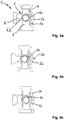
- FIGS. 6a, 6b show a second embodiment of the three-way mixer 1, in which the diaphragm 10 instead of the actuating arm has a sealed axis 28 which is accessible via an opening 29 of the sealed second bearing cap 23.
- the diaphragm 10 By manually rotating the shaft 28 via the hand wheel 30, the diaphragm 10 can be rotated and thus the flow of the three-way mixer 1 can be adjusted.
- the opening 29 (with surrounding Einrastkranz) will be fixed after the adjustment made by tightening the screw to the handwheel 30 .
- the throttle element is formed by a in the cylindrical bore 3 in front of the outlet 7 axially displaceable, eg cylindrical throttle body 10', which is actuated by means of a spindle drive 31 from the outside.
- the spindle of the spindle drive 31 is sealed in a bearing plate 32 slidably guided, which closes the opening of the cylindrical bore 3 tight.
- the throttle body 10 ' is arranged concentrically within the rotary valve 4, not shown. By rotating the spindle, the throttle body 10 'can be moved back and forth in front of the outlet 7 in the direction of the double arrow and thus the flow of the three-way mixer 1' more or less reduced.
- the rotary valve 4 and the aperture 10 are also mounted reversed, ie at the other opening of the cylindrical bore. 3
Abstract
Ein Dreiwegemischer (1) aufweisend ein Mischergehäuse (2) mit einer zylindrischen Bohrung (3), mit einer ersten und einer zweiten Einlassöffnung (5, 6), die beide mantelseitig in die zylindrische Bohrung (3) münden, und mit einer Auslassöffnung (7), die mantelseitig von der zylindrischen Bohrung (3) abgeht, sowie einen in der zylindrischen Bohrung (3) um die Zylinderachse (8) drehbar gelagerten, von außen betätigbaren Drehschieber (4) in Form einer um die Zylinderachse (8) teilkreisförmig ausgebildeten Sperrwand, die zwischen einer ersten Sperrstellung, in der der erste Einlass (5) abgesperrt ist, und einer zweiten Sperrstellung, in der der zweite Einlass (6) abgesperrt ist, verdrehbar ist, um das Mischungsverhältnis der beiden Einlassöffnungen (5, 6) einzustellen, weist erfindungsgemäß ein in der zylindrischen Bohrung (3) vor dem Auslass (7) oder in dem Auslass (7) beweglich gelagertes, von außen betätigbares Drosselelement (10) zum Einstellen des Durchflusses durch den Auslass (7) auf.A three-way mixer (1) comprising a mixer housing (2) with a cylindrical bore (3), with a first and a second inlet opening (5, 6), both of which open into the cylindrical bore (3) on the shell side, and with an outlet opening (7 ), the coat side of the cylindrical bore (3) goes off, as well as in the cylindrical bore (3) about the cylinder axis (8) rotatably mounted, externally operable rotary valve (4) in the form of a circular axis around the cylinder (8) part-circular barrier wall which is rotatable between a first blocking position, in which the first inlet (5) is shut off, and a second blocking position, in which the second inlet (6) is shut off, in order to adjust the mixing ratio of the two inlet openings (5, 6), has according to the invention in the cylindrical bore (3) in front of the outlet (7) or in the outlet (7) movably mounted, externally operable throttle element (10) for adjusting the flow through the A outlet (7).
Description
Die vorliegende Erfindung betrifft einen Dreiwegemischer aufweisend ein Mischergehäuse mit einer zylindrischen Bohrung, mit einem ersten und einem zweiten Einlass, die beide mantelseitig in die zylindrische Bohrung münden, und mit einem Auslass, der mantelseitig von der zylindrischen Bohrung abgeht, sowie einen in der zylindrischen Bohrung um die Zylinderachse drehbar gelagerten, von außen betätigbaren Drehschieber in Form einer um die Zylinderachse teilkreisförmig ausgebildeten Sperrwand, die zwischen einer ersten Sperrstellung, in der der erste Einlass abgesperrt ist, und einer zweiten Sperrstellung, in der der zweite Einlass abgesperrt ist, verdrehbar ist, um das Mischungsverhältnis der beiden Einlasse einzustellen.The present invention relates to a three-way mixer comprising a mixer housing having a cylindrical bore, with a first and a second inlet, both of which open into the cylindrical bore on the shell side, and with an outlet, the shell side of the cylindrical bore and one in the cylindrical bore rotatably mounted about the cylinder axis, operable from the outside rotary valve in the form of a part-circular around the cylinder axis formed barrier wall which between a first blocking position, in which the first inlet shut off , and a second blocking position in which the second inlet is shut off, is rotatable to adjust the mixing ratio of the two inlets.
Derartige Dreiwegemischer sind bekannt und werden zwischen Kesselvorlauf und Heizungsvorlauf einer Heizungsanlage angeordnet, um in Heizungsanlagen, bei denen die Kesseltemperatur technisch bedingt oberhalb der Vorlauftemperatur liegt, die Vorlauftemperatur abzusenken. Dem vom Heizkessel kommenden heißen Wasser des Kesselvorlaufs wird im Dreiwegemischer das beispielsweise von einer Fußbodenheizung kommende kühlere Rücklaufwasser beigemischt, um die Wassertemperatur des der Fußbodenheizung zugeführten Heizungsvorlaufs auf einen gewünschten Wert zu verringern. Der erste Eingang wird an den Kesselvorlauf z.B. einer Ölheizung, der zweite Eingang an den Heizungsrücklauf der Fußbodenheizung und der Ausgang an den Heizungsvorlauf der Fußbodenheizung angeschlossen. Der Drehschieber, auch Mischer-Küken genannt, ist als eine sich teilkreisförmig um die Zylinderachse ersteckende Sperrwand ausgebildet, die um 90° zwischen einer ersten Sperrstellung, in der sie den ersten Einlass absperrt, und einer zweiten Sperrstellung, in der sie den zweiten Einlass absperrt, verdrehbar, um das Mischungsverhältnis der beiden Einlasse einzustellen. Die Stellung des Drehschiebers kann manuell oder auch über einen elektrischen Antrieb (Stellmotor) erfolgen. Je nach erforderlicher Vorlauftemperatur schaltet die Heizungsregelung den Antrieb für einige Sekunden entweder in die eine oder andere Richtung, damit der Drehschieber die Einlässe jeweils sperrt oder unterschiedlich weit freigibt. Damit sich der Drehschieber leicht durch den Antrieb drehen lässt, ist zwangsweise etwas Spiel zwischen dem Drehschieber und der zylindrischen Bohrung notwendig bzw. vorhanden. Durch dieses Spiel ergibt sich allerdings eine Leckage in Abhängigkeit vom Volumenstrom, die zu einem Regelungsproblem führen kann.Such three-way mixers are known and are arranged between boiler flow and heating flow of a heating system to lower the flow temperature in heating systems where the boiler temperature is technically above the flow temperature. The coming of the boiler hot water boiler flow is mixed in the three-way mixer, for example, coming from a floor heating cooler return water to reduce the water temperature of the underfloor heating supplied heating flow to a desired value. The first input is sent to the boiler feed, e.g. an oil heater, the second input connected to the heating return of the floor heating and the output to the heating flow of the floor heating. The rotary valve, also called mixer-chick, is designed as a partially circular shape around the cylinder axis ersteckende barrier wall which is 90 ° between a first blocking position in which it shuts off the first inlet, and a second blocking position in which it shuts off the second inlet , rotatable to adjust the mixing ratio of the two inlets. The position of the rotary valve can be done manually or via an electric drive (servomotor). Depending on the required flow temperature, the heating control switches the drive either in one direction or the other for a few seconds so that the rotary valve blocks the inlets or releases them differently. Thus, the rotary valve can be easily rotated by the drive, forcibly some play between the rotary valve and the cylindrical bore is necessary or available. By this game, however, there is a leakage depending on the flow rate, which can lead to a control problem.
Für eine ordnungsgemäße Regelfunktion ist die Bestimmung der erforderlichen Leistungsgröße des Dreiwegemischers entscheidend. Bei Dreiwegemischern werden zum einen die Gehäusegrößen (DN) als auch die entstehenden Druckverlustklassen (KVS) unterschieden. Wird ein zu groß dimensionierter Dreiwegemischer (d.h. mit zu hohem KVS-Wert) verwendet, kommt es zum Überschwingen der Regelfunktion. Der Stellmotor muss häufig nachregulieren, was zu erhöhten Verschleiß führt. Wird ein Dreiwegemischer mit zu kleinem KVS-Wert eingesetzt, kann die erforderliche Leistung nicht übertragen werden. Aus diesem Grund werden Dreiwegemischer in einer Vielzahl von Bau- und Leistungsgrößen angeboten. Es obliegt dem Planer einer Heizungsanlage, das richtige Produkt auszuwählen. Eine spätere Korrektur ist immer mit erheblichen Zusatzkosten und Aufwand verbunden. Es sind auch Dreiwegemischer bekannt, bei denen nachträglich zusätzliche Blenden eingebaut werden können, um einen gewünschten KVS-Wert zu erreichen. Nachteilig ist jedoch, dass ein zusätzliches Bauteil benötigt wird und bei nachträglichen Anpassungen die Heizungsanlage zuvor entleert werden muss.For a proper control function, the determination of the required capacity of the three-way mixer is crucial. In the case of three-way mixers, a distinction is made between the housing sizes (DN) and the resulting pressure loss classes (KVS). If an oversized three-way mixer (ie with too high KVS value) is used, the control function overshoots. The servo motor has to readjust frequently, which leads to increased wear. If a three-way mixer with a too low KVS value is used, the required power may be required not be transferred. For this reason, three-way mixers are offered in a variety of construction and performance sizes. It is up to the planner of a heating system to select the right product. A subsequent correction is always associated with significant additional costs and effort. There are also known three-way mixers in which additional screens can be retrofitted to achieve a desired KVS value. The disadvantage, however, is that an additional component is needed and in subsequent adjustments the heating system must be emptied before.
Es ist demgegenüber die Aufgabe der Erfindung, einen Dreiwegemischer der eingangs genannten Art dahingehend weiterzubilden, dass der KVS-Wert ohne zusätzliche Bauteile eingestellt und somit auf die bisher handelsüblichen Dreiwegemischervarianten mit unterschiedlichem KVS-Wert verzichtet werden kann.It is the object of the invention to develop a three-way mixer of the type mentioned in that the KVS value can be set without additional components and thus can be dispensed with the previously commercially available Dreiwegemischervarianten with different KVS value.
Diese Aufgabe wird bei dem eingangs genannten Dreiwegemischer erfindungsgemäß durch ein in der zylindrischen Bohrung vor dem Auslass oder in dem Auslass beweglich gelagertes, von außen betätigbares Drosselelement zum Einstellen des Durchflusses durch den Auslass gelöst.This object is achieved in the aforementioned three-way mixer according to the invention by a in the cylindrical bore in front of the outlet or in the outlet movably mounted, externally operable throttle element for adjusting the flow through the outlet.
Die Duchflussverstellung (KVS-Wertverstellung) kann durch Bewegen des Drosselelements jederzeit ohne Entleeren der Heizungsanlage erfolgen. Es werden keine zusätzlichen Bauteile benötigt. Der Heizungsbauer, Großhändler oder Kesselhersteller erspart sich die Einlagerung von unterschiedlichen Mischern (oder Pumpengruppen) für die unterschiedlichen Leistungsklassen. Eine spätere Anpassung im realen Betrieb ist ohne Aufwand möglich.The flow rate adjustment (KVS value adjustment) can be done by moving the throttle element at any time without emptying the heating system. There are no additional components needed. The heating engineer, wholesaler or boiler manufacturer saves the storage of different mixers (or pump groups) for the different performance classes. A later adjustment in real operation is possible without effort.
In einer besonders bevorzugten Ausführungsform der Erfindung ist das Drosselelement durch eine in der zylindrischen Bohrung um die Zylinderachse drehbar gelagerte, von außen betätigbare Blende gebildet ist, die den Durchfluss durch den Auslass einstellt. Durch Verdrehen der KVS-Blende kann der KVS-Wert des Dreiwegemischers stufenlos auf den gewünschten KVS-Wert eingestellt werden. Vorzugsweise erstreckt sich die Blende teilkreisförmig um die Zylinderachse auf einem Radius erstreckt, der kleiner ist als der Radius der Sperrwand des Drehschiebers. Vorteilhaft ist die Blende hülsenförmig mit einer sich in Umfangsrichtung erstreckenden Blendenöffnung ausgebildet, welche sich auf der axialen Höhe des Auslasses befindet. Die Blende kann mittels eines Betätigungshebels oder einer abgedichteten Achse verdreht werden. Über den Betätigungshebel kann die KVS-Blende auch noch nach dem Einbau verstellt werden, also auch wenn die Anlage bereits gefüllt ist und unter Druck steht.In a particularly preferred embodiment of the invention, the throttle element is formed by a rotatably mounted in the cylindrical bore about the cylinder axis, externally operable diaphragm, which adjusts the flow through the outlet. By turning the KVS shutter, the KVS value of the three-way mixer can be infinitely adjusted to the desired KVS value. Preferably, the aperture extends part-circular around the cylinder axis to a radius which is smaller than the radius of the barrier wall of the rotary valve. Advantageously, the panel is sleeve-shaped with a circumferentially extending aperture formed, which is located at the axial height of the outlet. The diaphragm can be rotated by means of an actuating lever or a sealed axle. The KVS cover can also be adjusted after installation via the operating lever, even if the system is already filled and under pressure.
In einer bevorzugten Weiterbildung weist die Sperrwand des Drehschiebers an ihren beiden axialen Enden jeweils zwei einander zugewandte Federarme auf, welche einen größeren Radius als die zylindische Bohrung aufweisen. In einer anderen bevorzugten Weiterbildung ist die Sperrwand des Drehschiebers an ihren beiden axialen Enden jeweils über Federarme mit einer Rückwand verbunden, welche einen größeren Radius als die zylindische Bohrung aufweist. Der Drehschieber ist abgedichtet in der einen Öffnung und die Blende abgedichtet in der anderen Öffnung der zylindrischen Bohrung angeordnet, sowie drehbar gelagert. Beim Einbau des Drehschiebers in die zylindrische Bohrung werden die beiden Federarme bzw. die Rückwand radial nach innen auf den Radius der zylindrischen Bohrung elastisch gedrückt, wodurch die Sperrwand gegen die Bohrungswand bzw. die jeweilige Einlassöffnung gedrückt wird. Das radiale Spiel wird auf ein Minimum reduziert und somit Leckage minimiert.In a preferred embodiment, the barrier wall of the rotary valve at its two axial ends in each case two mutually facing spring arms, which have a larger radius than the cylindrical bore. In another preferred embodiment, the barrier wall of the rotary valve is connected at its two axial ends in each case via spring arms with a rear wall, which has a larger radius than the cylindrical bore. The rotary valve is sealed in the one opening and the aperture sealed arranged in the other opening of the cylindrical bore, and rotatably supported. When installing the rotary valve in the cylindrical bore, the two spring arms and the rear wall are pressed radially inwardly to the radius of the cylindrical bore, whereby the barrier wall is pressed against the bore wall or the respective inlet opening. The radial play is reduced to a minimum, thus minimizing leakage.
In anderen Ausführungsformen der Erfindung kann das Drosselelement auch durch einen in der zylindrischen Bohrung vor dem Auslass axial verschiebbaren, von außen betätigbaren Drosselkörper oder durch einen im Auslass querverschiebbar geführten, von außen betätigbaren Schieber gebildet sein.In other embodiments of the invention, the throttle element may also be formed by a in the cylindrical bore in front of the outlet axially displaceable, operable from the outside throttle body or by a transversely displaceably guided in the outlet, externally operable slide.
Vorzugsweise sind das Mischergehäuse aus Metall (z.B. Messing) und die übrigen Komponenten des Dreiwegemischers aus Kunststoff gebildet.Preferably, the mixer housing is made of metal (e.g., brass) and the remaining components of the three-way mixer are plastic.
Weitere Vorteile und vorteilhafte Ausgestaltungen des Gegenstands der Erfindung sind der Beschreibung, der Zeichnung und den Ansprüchen entnehmbar. Ebenso können die vorstehend genannten und die noch weiter aufgeführten Merkmale je für sich oder zu mehreren in beliebigen Kombinationen Verwendung finden. Die gezeigten und beschriebenen Ausführungsformen sind nicht als abschließende Aufzählung zu verstehen, sondern haben vielmehr beispielhaften Charakter für die Schilderung der Erfindung.Further advantages and advantageous embodiments of the subject invention are the description, the drawings and claims removed. Likewise, the features mentioned above and the features listed further can be used individually or in combination in any combination. The embodiments shown and described are not to be understood as exhaustive enumeration, but rather have exemplary character for the description of the invention.
Es zeigen:
- Fig. 1
- schematisch einen erfindungsgemäßen Dreiwegemischer mit einer Drosselblende zum Einstellen des KVS-Werts;
- Fign. 2a, 2b
- eine erste Ausführungsform des in
Fig. 1 gezeigten erfindungsgemäßen Dreiwegemischers in einer perspektivischen Seitenansicht (Fig. 2a ) und in einer Explosionsdarstellung (Fig. 2b ); - Fign. 3a, 3b
- einen Drehschieber (
Fig. 3a ) und eine Drosselblende (Fig. 3b ) des inFig. 2 gezeigten Dreiwegemischers; - Fign. 4a bis 4c
- einen Längsschnitt des in
Fig. 2 gezeigten Dreiwegemischers mit der Drosselblende in verschiedenen Drehstellungen; - Fig. 5
- einen modifierten Drehschieber;
- Fign. 6a, 6b
- eine zweite Ausführungsform des in
Fig. 1 gezeigten erfindungsgemäßen Dreiwegemischers in einer perspektivischen Seitenansicht (Fig. 6a ) und in einer Einzelteildarstellung (Fig. 6b ); - Fig. 7
- schematisch einen erfindungsgemäßen Dreiwegemischer mit einem axial verschiebbaren Drosselkörper zum Einstellen des KVS-Werts in einer Schnittansicht; und
- Fig. 8
- schematisch einen erfindungsgemäßen Dreiwegemischer mit einem querverschiebbaren Schieber zum Einstellen des KVS-Werts in einem Längsschnitt.
- Fig. 1
- schematically a three-way mixer according to the invention with an orifice for setting the KVS value;
- FIGS. 2a, 2b
- a first embodiment of the in
Fig. 1 shown three-way mixer according to the invention in a perspective side view (Fig. 2a ) and in an exploded view (Fig. 2b ); - FIGS. 3a, 3b
- a rotary valve (
Fig. 3a ) and an orifice (Fig. 3b ) of theFig. 2 three-way mixer shown; - FIGS. 4a to 4c
- a longitudinal section of in
Fig. 2 shown three-way mixer with the orifice in different rotational positions; - Fig. 5
- a modified rotary valve;
- FIGS. 6a, 6b
- a second embodiment of the in
Fig. 1 shown three-way mixer according to the invention in a perspective side view (Fig. 6a ) and in a single part representation (Fig. 6b ); - Fig. 7
- schematically a three-way mixer according to the invention with an axially displaceable throttle body for adjusting the KVS value in a sectional view; and
- Fig. 8
- schematically a three-way mixer according to the invention with a transversely displaceable slide for adjusting the KVS value in a longitudinal section.
Der in
Der Dreiwegemischer 1 umfasst ein Mischergehäuse 2 mit einer zylindrischen Bohrung (Mischerkammer) 3 sowie einen in der zylindrischen Bohrung 3 drehbar gelagerten Drehschieber 4. Das Mischergehäuse 2 hat einen ersten und einen zweiten Einlass 5, 6, die beide mantelseitig in die zylindrische Bohrung 3 münden, und einen Auslass 7, der mantelseitig von der Mischerkammer 3 abgeht. Der erste Eingang 5 wird an den Kesselvorlauf (z.B. einer Ölheizung), der zweite Eingang 6 an den Heizungsrücklauf einer Fußbodenheizung und der Ausgang 7 an den Heizungsvorlauf der Fußbodenheizung angeschlossen. Dem vom Heizkessel kommenden heißen Wasser des Kesselvorlaufs wird im Dreiwegemischer 1 das von der Fußbodenheizung kommende kühlere Rücklaufwasser beigemischt, um die Wassertemperatur des der Fußbodenheizung zugeführten Heizungsvorlaufs auf einen gewünschten Wert zu verringern.The three-way mixer 1 comprises a
Der Drehschieber 4 ist als eine sich etwa viertelkreisförmig um die Zylinderachse 8 ersteckende Sperrwand 9 ausgebildet, die - hier um 90° - zwischen einer ersten Sperrstellung, in der sie den ersten Einlass 5 absperrt, und einer zweiten Sperrstellung, in der sie den zweiten Einlass 6 absperrt, um die Zylinderachse 8 verdrehbar, um das Mischungsverhältnis der beiden Einlasse 5, 6 einzustellen.The rotary valve 4 is formed as an approximately quarter-circle around the
Zum Einstellen des Durchflusses durch den Auslass 7 ist in der zylindrischen Bohrung 3 eine um die Zylinderachse 8 teilkreisförmig ausgebildete, von außen betätigbare Blende 10 drehbar um die Zylinderachse 8 gelagert, und zwar auf einem kleineren Radius als die Sperrwand 9. Die Blende 10 ist konzentrisch zu der Sperrwand 9 drehbar gelagert und bildet ein vor dem Auslass 7 angeordnetes Drosselelement. Je nach Stellung der Blende 10 wird der Durchfluss durch den Auslass 7 mehr oder weniger reduziert.To adjust the flow through the
Wie in
Wie in
Vom Drehschieber der
Vom Drehschieber der
Bei den in
Vom Drehschieber der
Claims (12)
Priority Applications (2)
| Application Number | Priority Date | Filing Date | Title |
|---|---|---|---|
| EP18159682.6A EP3534075B1 (en) | 2018-03-02 | 2018-03-02 | Three-way mixer with adjustable kvs value |
| PL18159682T PL3534075T3 (en) | 2018-03-02 | 2018-03-02 | Three-way mixer with adjustable kvs value |
Applications Claiming Priority (1)
| Application Number | Priority Date | Filing Date | Title |
|---|---|---|---|
| EP18159682.6A EP3534075B1 (en) | 2018-03-02 | 2018-03-02 | Three-way mixer with adjustable kvs value |
Publications (2)
| Publication Number | Publication Date |
|---|---|
| EP3534075A1 true EP3534075A1 (en) | 2019-09-04 |
| EP3534075B1 EP3534075B1 (en) | 2020-02-26 |
Family
ID=61563186
Family Applications (1)
| Application Number | Title | Priority Date | Filing Date |
|---|---|---|---|
| EP18159682.6A Active EP3534075B1 (en) | 2018-03-02 | 2018-03-02 | Three-way mixer with adjustable kvs value |
Country Status (2)
| Country | Link |
|---|---|
| EP (1) | EP3534075B1 (en) |
| PL (1) | PL3534075T3 (en) |
Cited By (2)
| Publication number | Priority date | Publication date | Assignee | Title |
|---|---|---|---|---|
| DE202021101874U1 (en) | 2021-04-08 | 2021-06-21 | Elodrive Gmbh | Mixer with adjustable KVS value |
| DE102021108732A1 (en) | 2021-04-08 | 2022-10-13 | Elodrive Gmbh | Mixer with adjustable KVS value |
Citations (4)
| Publication number | Priority date | Publication date | Assignee | Title |
|---|---|---|---|---|
| DE1909759U (en) * | 1962-03-19 | 1965-02-11 | Ludwig Siber | MIXING AND CIRCULATION PUMP FOR HOT WATER HEATING AND HOT WATER HEATING SYSTEMS IN ONE HOUSING WITH FOUR CONNECTORS. |
| DE3828206C1 (en) * | 1988-08-19 | 1989-11-02 | Wilo-Werk Gmbh & Co Pumpen- Und Apparatebau, 4600 Dortmund, De | |
| JP2013044415A (en) * | 2011-08-25 | 2013-03-04 | Fuji Koki Corp | Flow path switching valve |
| DE202017101386U1 (en) * | 2017-03-10 | 2017-05-10 | Watts Industries Deutschland Gmbh | fitting |
-
2018
- 2018-03-02 PL PL18159682T patent/PL3534075T3/en unknown
- 2018-03-02 EP EP18159682.6A patent/EP3534075B1/en active Active
Patent Citations (4)
| Publication number | Priority date | Publication date | Assignee | Title |
|---|---|---|---|---|
| DE1909759U (en) * | 1962-03-19 | 1965-02-11 | Ludwig Siber | MIXING AND CIRCULATION PUMP FOR HOT WATER HEATING AND HOT WATER HEATING SYSTEMS IN ONE HOUSING WITH FOUR CONNECTORS. |
| DE3828206C1 (en) * | 1988-08-19 | 1989-11-02 | Wilo-Werk Gmbh & Co Pumpen- Und Apparatebau, 4600 Dortmund, De | |
| JP2013044415A (en) * | 2011-08-25 | 2013-03-04 | Fuji Koki Corp | Flow path switching valve |
| DE202017101386U1 (en) * | 2017-03-10 | 2017-05-10 | Watts Industries Deutschland Gmbh | fitting |
Cited By (2)
| Publication number | Priority date | Publication date | Assignee | Title |
|---|---|---|---|---|
| DE202021101874U1 (en) | 2021-04-08 | 2021-06-21 | Elodrive Gmbh | Mixer with adjustable KVS value |
| DE102021108732A1 (en) | 2021-04-08 | 2022-10-13 | Elodrive Gmbh | Mixer with adjustable KVS value |
Also Published As
| Publication number | Publication date |
|---|---|
| PL3534075T3 (en) | 2020-07-27 |
| EP3534075B1 (en) | 2020-02-26 |
Similar Documents
| Publication | Publication Date | Title |
|---|---|---|
| DE2953331C1 (en) | Control and shut-off valve for flowing media | |
| EP0242675A2 (en) | Mixing valve | |
| EP2171325A1 (en) | Adjusting device | |
| WO2006097200A1 (en) | Flow regulator | |
| DE2608791A1 (en) | MODULATING FLOW CONTROL VALVE ARRANGEMENT | |
| EP3534075B1 (en) | Three-way mixer with adjustable kvs value | |
| EP0816730B1 (en) | Device for limiting the prestress of a control spring | |
| EP1261822B1 (en) | Temperature-controlled mixer valve | |
| EP3499103A1 (en) | Valve actuation device and sanitary valve | |
| WO2006092655A2 (en) | Device for dynamically controlling a water flow | |
| EP0501953B1 (en) | Tap-water mixer unit | |
| DE102005011947B3 (en) | Continuous flow controller, has controlling mechanisms designed for different flow rate capacities and/or pressure ranges, where one mechanism exhibits opening that acts as bypass channel, which is openable and closeable | |
| DE4016221A1 (en) | ARRANGEMENT AND METHOD FOR CONTROLLING THE WATER QUANTITY RATIO FROM BOILER CIRCUIT TO HEATING CIRCUIT IN HOT WATER HEATING SYSTEMS | |
| EP0844421B1 (en) | Cartridge for a mixing valve | |
| DE2110686A1 (en) | Thermostatically controlled hot water mixer | |
| DE3432731A1 (en) | Thermostatically controlled concealed fitting | |
| DE69534320T2 (en) | VALVE FOR A HEAT TRANSFER SYSTEM | |
| DE102004049253B4 (en) | thermostatic valve | |
| EP3467358A1 (en) | Directional control valve | |
| CH691823A5 (en) | Diaphragm valve. | |
| DE1206241B (en) | Mixer tap with automatic regulation of the outflowing water | |
| EP3376082B1 (en) | Valve device | |
| DE2156384A1 (en) | Mixing valve and thermostat that can be used on this | |
| EP3596342B1 (en) | Centrifugal pump assembly | |
| EP0122973B1 (en) | Mixing valve |
Legal Events
| Date | Code | Title | Description |
|---|---|---|---|
| PUAI | Public reference made under article 153(3) epc to a published international application that has entered the european phase |
Free format text: ORIGINAL CODE: 0009012 |
|
| STAA | Information on the status of an ep patent application or granted ep patent |
Free format text: STATUS: REQUEST FOR EXAMINATION WAS MADE |
|
| 17P | Request for examination filed |
Effective date: 20190108 |
|
| AK | Designated contracting states |
Kind code of ref document: A1 Designated state(s): AL AT BE BG CH CY CZ DE DK EE ES FI FR GB GR HR HU IE IS IT LI LT LU LV MC MK MT NL NO PL PT RO RS SE SI SK SM TR |
|
| AX | Request for extension of the european patent |
Extension state: BA ME |
|
| REG | Reference to a national code |
Ref country code: DE Ref legal event code: R079 Ref document number: 502018000802 Country of ref document: DE Free format text: PREVIOUS MAIN CLASS: F24D0019100000 Ipc: F16K0011076000 |
|
| GRAP | Despatch of communication of intention to grant a patent |
Free format text: ORIGINAL CODE: EPIDOSNIGR1 |
|
| STAA | Information on the status of an ep patent application or granted ep patent |
Free format text: STATUS: GRANT OF PATENT IS INTENDED |
|
| RIC1 | Information provided on ipc code assigned before grant |
Ipc: F16K 11/076 20060101AFI20190912BHEP Ipc: F24D 19/10 20060101ALI20190912BHEP Ipc: F16K 11/085 20060101ALI20190912BHEP Ipc: F16K 5/10 20060101ALI20190912BHEP |
|
| INTG | Intention to grant announced |
Effective date: 20191007 |
|
| RIN1 | Information on inventor provided before grant (corrected) |
Inventor name: VALTIN, ANDREAS Inventor name: VON OLNHAUSEN, THOMAS Inventor name: HEINZ, THOMAS |
|
| GRAS | Grant fee paid |
Free format text: ORIGINAL CODE: EPIDOSNIGR3 |
|
| GRAA | (expected) grant |
Free format text: ORIGINAL CODE: 0009210 |
|
| STAA | Information on the status of an ep patent application or granted ep patent |
Free format text: STATUS: THE PATENT HAS BEEN GRANTED |
|
| AK | Designated contracting states |
Kind code of ref document: B1 Designated state(s): AL AT BE BG CH CY CZ DE DK EE ES FI FR GB GR HR HU IE IS IT LI LT LU LV MC MK MT NL NO PL PT RO RS SE SI SK SM TR |
|
| REG | Reference to a national code |
Ref country code: GB Ref legal event code: FG4D Free format text: NOT ENGLISH |
|
| REG | Reference to a national code |
Ref country code: CH Ref legal event code: EP |
|
| REG | Reference to a national code |
Ref country code: DE Ref legal event code: R096 Ref document number: 502018000802 Country of ref document: DE |
|
| REG | Reference to a national code |
Ref country code: AT Ref legal event code: REF Ref document number: 1238037 Country of ref document: AT Kind code of ref document: T Effective date: 20200315 |
|
| REG | Reference to a national code |
Ref country code: IE Ref legal event code: FG4D Free format text: LANGUAGE OF EP DOCUMENT: GERMAN |
|
| PG25 | Lapsed in a contracting state [announced via postgrant information from national office to epo] |
Ref country code: RS Free format text: LAPSE BECAUSE OF FAILURE TO SUBMIT A TRANSLATION OF THE DESCRIPTION OR TO PAY THE FEE WITHIN THE PRESCRIBED TIME-LIMIT Effective date: 20200226 Ref country code: NO Free format text: LAPSE BECAUSE OF FAILURE TO SUBMIT A TRANSLATION OF THE DESCRIPTION OR TO PAY THE FEE WITHIN THE PRESCRIBED TIME-LIMIT Effective date: 20200526 Ref country code: FI Free format text: LAPSE BECAUSE OF FAILURE TO SUBMIT A TRANSLATION OF THE DESCRIPTION OR TO PAY THE FEE WITHIN THE PRESCRIBED TIME-LIMIT Effective date: 20200226 |
|
| REG | Reference to a national code |
Ref country code: NL Ref legal event code: MP Effective date: 20200226 |
|
| REG | Reference to a national code |
Ref country code: LT Ref legal event code: MG4D |
|
| PG25 | Lapsed in a contracting state [announced via postgrant information from national office to epo] |
Ref country code: SE Free format text: LAPSE BECAUSE OF FAILURE TO SUBMIT A TRANSLATION OF THE DESCRIPTION OR TO PAY THE FEE WITHIN THE PRESCRIBED TIME-LIMIT Effective date: 20200226 Ref country code: LV Free format text: LAPSE BECAUSE OF FAILURE TO SUBMIT A TRANSLATION OF THE DESCRIPTION OR TO PAY THE FEE WITHIN THE PRESCRIBED TIME-LIMIT Effective date: 20200226 Ref country code: HR Free format text: LAPSE BECAUSE OF FAILURE TO SUBMIT A TRANSLATION OF THE DESCRIPTION OR TO PAY THE FEE WITHIN THE PRESCRIBED TIME-LIMIT Effective date: 20200226 Ref country code: BG Free format text: LAPSE BECAUSE OF FAILURE TO SUBMIT A TRANSLATION OF THE DESCRIPTION OR TO PAY THE FEE WITHIN THE PRESCRIBED TIME-LIMIT Effective date: 20200526 Ref country code: GR Free format text: LAPSE BECAUSE OF FAILURE TO SUBMIT A TRANSLATION OF THE DESCRIPTION OR TO PAY THE FEE WITHIN THE PRESCRIBED TIME-LIMIT Effective date: 20200527 Ref country code: IS Free format text: LAPSE BECAUSE OF FAILURE TO SUBMIT A TRANSLATION OF THE DESCRIPTION OR TO PAY THE FEE WITHIN THE PRESCRIBED TIME-LIMIT Effective date: 20200626 |
|
| PG25 | Lapsed in a contracting state [announced via postgrant information from national office to epo] |
Ref country code: NL Free format text: LAPSE BECAUSE OF FAILURE TO SUBMIT A TRANSLATION OF THE DESCRIPTION OR TO PAY THE FEE WITHIN THE PRESCRIBED TIME-LIMIT Effective date: 20200226 |
|
| PG25 | Lapsed in a contracting state [announced via postgrant information from national office to epo] |
Ref country code: SK Free format text: LAPSE BECAUSE OF FAILURE TO SUBMIT A TRANSLATION OF THE DESCRIPTION OR TO PAY THE FEE WITHIN THE PRESCRIBED TIME-LIMIT Effective date: 20200226 Ref country code: RO Free format text: LAPSE BECAUSE OF FAILURE TO SUBMIT A TRANSLATION OF THE DESCRIPTION OR TO PAY THE FEE WITHIN THE PRESCRIBED TIME-LIMIT Effective date: 20200226 Ref country code: LT Free format text: LAPSE BECAUSE OF FAILURE TO SUBMIT A TRANSLATION OF THE DESCRIPTION OR TO PAY THE FEE WITHIN THE PRESCRIBED TIME-LIMIT Effective date: 20200226 Ref country code: CZ Free format text: LAPSE BECAUSE OF FAILURE TO SUBMIT A TRANSLATION OF THE DESCRIPTION OR TO PAY THE FEE WITHIN THE PRESCRIBED TIME-LIMIT Effective date: 20200226 Ref country code: DK Free format text: LAPSE BECAUSE OF FAILURE TO SUBMIT A TRANSLATION OF THE DESCRIPTION OR TO PAY THE FEE WITHIN THE PRESCRIBED TIME-LIMIT Effective date: 20200226 Ref country code: SM Free format text: LAPSE BECAUSE OF FAILURE TO SUBMIT A TRANSLATION OF THE DESCRIPTION OR TO PAY THE FEE WITHIN THE PRESCRIBED TIME-LIMIT Effective date: 20200226 Ref country code: EE Free format text: LAPSE BECAUSE OF FAILURE TO SUBMIT A TRANSLATION OF THE DESCRIPTION OR TO PAY THE FEE WITHIN THE PRESCRIBED TIME-LIMIT Effective date: 20200226 Ref country code: ES Free format text: LAPSE BECAUSE OF FAILURE TO SUBMIT A TRANSLATION OF THE DESCRIPTION OR TO PAY THE FEE WITHIN THE PRESCRIBED TIME-LIMIT Effective date: 20200226 Ref country code: PT Free format text: LAPSE BECAUSE OF FAILURE TO SUBMIT A TRANSLATION OF THE DESCRIPTION OR TO PAY THE FEE WITHIN THE PRESCRIBED TIME-LIMIT Effective date: 20200719 |
|
| REG | Reference to a national code |
Ref country code: DE Ref legal event code: R097 Ref document number: 502018000802 Country of ref document: DE |
|
| PG25 | Lapsed in a contracting state [announced via postgrant information from national office to epo] |
Ref country code: MC Free format text: LAPSE BECAUSE OF FAILURE TO SUBMIT A TRANSLATION OF THE DESCRIPTION OR TO PAY THE FEE WITHIN THE PRESCRIBED TIME-LIMIT Effective date: 20200226 |
|
| REG | Reference to a national code |
Ref country code: BE Ref legal event code: MM Effective date: 20200331 |
|
| PG25 | Lapsed in a contracting state [announced via postgrant information from national office to epo] |
Ref country code: LU Free format text: LAPSE BECAUSE OF NON-PAYMENT OF DUE FEES Effective date: 20200302 |
|
| PLBE | No opposition filed within time limit |
Free format text: ORIGINAL CODE: 0009261 |
|
| STAA | Information on the status of an ep patent application or granted ep patent |
Free format text: STATUS: NO OPPOSITION FILED WITHIN TIME LIMIT |
|
| PG25 | Lapsed in a contracting state [announced via postgrant information from national office to epo] |
Ref country code: FR Free format text: LAPSE BECAUSE OF NON-PAYMENT OF DUE FEES Effective date: 20200426 Ref country code: IE Free format text: LAPSE BECAUSE OF NON-PAYMENT OF DUE FEES Effective date: 20200302 |
|
| 26N | No opposition filed |
Effective date: 20201127 |
|
| PG25 | Lapsed in a contracting state [announced via postgrant information from national office to epo] |
Ref country code: BE Free format text: LAPSE BECAUSE OF NON-PAYMENT OF DUE FEES Effective date: 20200331 |
|
| REG | Reference to a national code |
Ref country code: CH Ref legal event code: PL |
|
| PG25 | Lapsed in a contracting state [announced via postgrant information from national office to epo] |
Ref country code: LI Free format text: LAPSE BECAUSE OF NON-PAYMENT OF DUE FEES Effective date: 20210331 Ref country code: CH Free format text: LAPSE BECAUSE OF NON-PAYMENT OF DUE FEES Effective date: 20210331 |
|
| PG25 | Lapsed in a contracting state [announced via postgrant information from national office to epo] |
Ref country code: TR Free format text: LAPSE BECAUSE OF FAILURE TO SUBMIT A TRANSLATION OF THE DESCRIPTION OR TO PAY THE FEE WITHIN THE PRESCRIBED TIME-LIMIT Effective date: 20200226 Ref country code: MT Free format text: LAPSE BECAUSE OF FAILURE TO SUBMIT A TRANSLATION OF THE DESCRIPTION OR TO PAY THE FEE WITHIN THE PRESCRIBED TIME-LIMIT Effective date: 20200226 Ref country code: CY Free format text: LAPSE BECAUSE OF FAILURE TO SUBMIT A TRANSLATION OF THE DESCRIPTION OR TO PAY THE FEE WITHIN THE PRESCRIBED TIME-LIMIT Effective date: 20200226 |
|
| PG25 | Lapsed in a contracting state [announced via postgrant information from national office to epo] |
Ref country code: MK Free format text: LAPSE BECAUSE OF FAILURE TO SUBMIT A TRANSLATION OF THE DESCRIPTION OR TO PAY THE FEE WITHIN THE PRESCRIBED TIME-LIMIT Effective date: 20200226 Ref country code: AL Free format text: LAPSE BECAUSE OF FAILURE TO SUBMIT A TRANSLATION OF THE DESCRIPTION OR TO PAY THE FEE WITHIN THE PRESCRIBED TIME-LIMIT Effective date: 20200226 |
|
| GBPC | Gb: european patent ceased through non-payment of renewal fee |
Effective date: 20220302 |
|
| PG25 | Lapsed in a contracting state [announced via postgrant information from national office to epo] |
Ref country code: GB Free format text: LAPSE BECAUSE OF NON-PAYMENT OF DUE FEES Effective date: 20220302 |
|
| PGFP | Annual fee paid to national office [announced via postgrant information from national office to epo] |
Ref country code: PL Payment date: 20221222 Year of fee payment: 6 |
|
| PGFP | Annual fee paid to national office [announced via postgrant information from national office to epo] |
Ref country code: DE Payment date: 20230327 Year of fee payment: 6 |
|
| PGFP | Annual fee paid to national office [announced via postgrant information from national office to epo] |
Ref country code: IT Payment date: 20230331 Year of fee payment: 6 |
|
| PG25 | Lapsed in a contracting state [announced via postgrant information from national office to epo] |
Ref country code: SI Free format text: LAPSE BECAUSE OF FAILURE TO SUBMIT A TRANSLATION OF THE DESCRIPTION OR TO PAY THE FEE WITHIN THE PRESCRIBED TIME-LIMIT Effective date: 20200226 |