EP3534072B1 - Oven equipped with automatically ascending/descending tray - Google Patents
Oven equipped with automatically ascending/descending tray Download PDFInfo
- Publication number
- EP3534072B1 EP3534072B1 EP19160053.5A EP19160053A EP3534072B1 EP 3534072 B1 EP3534072 B1 EP 3534072B1 EP 19160053 A EP19160053 A EP 19160053A EP 3534072 B1 EP3534072 B1 EP 3534072B1
- Authority
- EP
- European Patent Office
- Prior art keywords
- ascending
- descending
- tray
- oven
- cavity
- Prior art date
- Legal status (The legal status is an assumption and is not a legal conclusion. Google has not performed a legal analysis and makes no representation as to the accuracy of the status listed.)
- Active
Links
Images



Classifications
-
- F—MECHANICAL ENGINEERING; LIGHTING; HEATING; WEAPONS; BLASTING
- F24—HEATING; RANGES; VENTILATING
- F24C—DOMESTIC STOVES OR RANGES ; DETAILS OF DOMESTIC STOVES OR RANGES, OF GENERAL APPLICATION
- F24C15/00—Details
- F24C15/16—Shelves, racks or trays inside ovens; Supports therefor
-
- A—HUMAN NECESSITIES
- A47—FURNITURE; DOMESTIC ARTICLES OR APPLIANCES; COFFEE MILLS; SPICE MILLS; SUCTION CLEANERS IN GENERAL
- A47B—TABLES; DESKS; OFFICE FURNITURE; CABINETS; DRAWERS; GENERAL DETAILS OF FURNITURE
- A47B57/00—Cabinets, racks or shelf units, characterised by features for adjusting shelves or partitions
- A47B57/06—Cabinets, racks or shelf units, characterised by features for adjusting shelves or partitions with means for adjusting the height of the shelves
-
- A—HUMAN NECESSITIES
- A47—FURNITURE; DOMESTIC ARTICLES OR APPLIANCES; COFFEE MILLS; SPICE MILLS; SUCTION CLEANERS IN GENERAL
- A47B—TABLES; DESKS; OFFICE FURNITURE; CABINETS; DRAWERS; GENERAL DETAILS OF FURNITURE
- A47B96/00—Details of cabinets, racks or shelf units not covered by a single one of groups A47B43/00 - A47B95/00; General details of furniture
- A47B96/06—Brackets or similar supporting means for cabinets, racks or shelves
Definitions
- the present disclosure relates to an oven and, more particularly, an oven including an ascending/descending structure configured to automatically adjust a height of a tray disposed in a cavity of the oven based on a type of food.
- An oven is a cooking device that may cook food by circulating high-temperature air in a sealed space.
- the oven may include a tray on which food is placed therein.
- a user may adjust a height of the tray in the sealed space (i.e., a cavity of the oven) based on a food item to be cooked.
- the user draws the tray out of the cavity in the state where the door of the oven is open, places the tray at a height adequate for cooking the selected food with reference to the optimum height, closes the door and then operates the oven.
- a structure for adjusting height of a tray in an oven is disclosed.
- a link structure is applied to the above-described structure to adjust height of a tray in an oven by height corresponding to the radius of gyration of the link.
- a tray may not be placed at a height twice as long as the link or more. Accordingly, the tray may be placed within a range of limited heights only. Additionally, space where the link structure may swivel is required, thereby making it difficult to ensure enough volume of a cavity. Further, with the structure, the user has to open the door of the oven and adjust height of the tray manually.
- a structure in which a rack and pinion structure is applied on the lateral surface of a cavity and operated by a gear box and an external synchronous motor to ascend and descend a tray is disclosed.
- the tray may ascend and descend in the state where the door of the oven is closed.
- the size of the oven increases while the width of the cavity does not increase because the gear box and external synchronous motor are installed on the lateral surface of the cavity.
- KR 1688740 a built-in oven where a tray automatically ascends and descends according to a series of predetermined sequences by means of operation of a control panel is disclosed.
- a motor 16 and a pulley 15 that generate and deliver the power for ascending and descending the tray are installed on the lateral surface of the cavity.
- the size of the oven increases while the width of the cavity does not increase.
- the ascending/descending structure for stably ascending and descending a tray is installed on both sides of the tray, i.e., on both walls of the cavity.
- elements relating to the ascending/descending structure are uncovered in the cooking space. Accordingly, foreign substances that pop while food is cooked are attached to the ascending/descending structure and contaminate the same, thereby causing the incorrect operation of the ascending/descending structure.
- WO 2017/102247 A1 discloses an oven comprising a housing which defines a coking chamber, a support element and a support rod positioned vertically in the vicinity of the rear wall of the housing.
- the support rod is configured to elevate a support element holding a tray to a selected height in the cooking chamber.
- ES 2 343 229 A1 discloses an oven comprising a system for automatic vertical displacement of trays.
- the system comprises one or more rods located inside or outside the oven and being driven by motors arranged outside the oven.
- WO 2013/026789 A1 shows an oven comprising a cooking cavity having at least one support on which trays containing foodstuffs can be placed and wherein the support can be vertically moved within the cooking cavity.
- JP S57 54332 U discloses a table grill comprising a cooking cavity and a grill disposed at the bottom of the cooking cavity.
- the table grill further comprises a heater holding frame provided inside of the cavity and configured to be automatically moved up and down within the cavity.
- EP 3 276 264 A1 relates to a movement device for a kitchen appliance having at least one receiving space for receiving objects and/or food and comprising a housing delimiting the receiving space, with at least one traction mechanism drive.
- the object of the present disclosure is to provide an oven that has a structure for automatically ascending and descending a tray in a cavity with a door of the oven being closed and for stably ascend-ing and descending the tray with an ascending/descending structure of the tray being not provided on the lateral surface of the cavity.
- a further object of the present disclosure is to provide an oven that has a structure for automatically ascending and descending a tray in the cavity and for ensuring maximization of a volume of the cavity.
- a further object of the present disclosure is to provide an oven that has a structure in which an ascending/descending structure for ascending and descending a tray in a cavity of the oven is prevented from being exposed, which may reduce an incorrect operation of the tray in the cavity caused by contamination of the ascending/descending structure.
- an oven includes an ascending/descending structure that is installed at both ends of the rear wall of a cavity and that takes up little space on both sides of the cavity serving as a cooking chamber, thereby ensuring a maximum space for cooking.
- the oven includes a rear cover that is installed at the front of the ascending/descending structure at the rear of the cavity and that separates the ascending/descending structure from the space for cooking, thereby preventing the ascending/descending structure from being contaminated by foreign substances that may pop while food is cooked in the space for cooking in the cavity.
- the rear cover is configured to circulate heat generated from a fan for circulating heat at the rear of the cavity of the oven, thereby preventing the ascending/descending structure from being contaminated as well as facilitating the circulation of the heat.
- the oven includes an ascending/descending structure that may support the moment and may facilitate the ascending and descending movement.
- the oven includes an ascending/descending rack that supports the tray, and the ascending/descending rack has two positions that are spaced apart from each other in the front-rear direction of the oven and to which the ascending/descending power is delivered so as to support a cantilever-structured tray.
- the ascending/descending rack that supports the tray is a member that has a predetermined height and that is supported by an ascending/descending guide rail, formed on the rear wall of the cavity and extending in the up-down direction, so as to ascend and descend, thereby making it possible to support the cantilever-structured tray and smoothly ascend and descend the same.
- the oven may include a fixed tray rack that is provided at the rear of the ascending/descending rack in the cavity and that extends in a direction parallel with the direction in which the ascending/descending rack ascends and descends.
- the fixed tray rack may include a plurality of holes that are provided at predetermined different heights of the fixed tray rack such that the ascending/descending rack is temporarily coupled to the hole at a predetermined height and stays at the height, thereby making it possible to allow a tray that is ascended and descended to stably stay at a height.
- another tray other than the tray installed in the ascending/descending rack may be installed, thereby making it possible to install a plurality of trays in the fixed tray rack.
- Implementations according to these aspects include an ascending/descending guide part on both rear sides of the cavity, an ascending/descending rack that is guided by the ascending/descending guide part to ascend and descend, and a first tray frame connecting part at the ascending/descending rack.
- the first tray frame connecting part also ascends and descends, and the height of the first tray frame connecting part may be determined.
- the ascending/descending rack includes ascending/descending connection parts, on which the ascending/descending guide part is mounted.
- the ascending/descending guide part is, according to the invention, covered with a rear cover and prevented from being contaminated by foreign substances during cooking.
- the rear cover does not cover the first tray frame connecting part such the first tray frame connecting part is exposed forward.
- the ascending/descending guide part may connect with a cavity rear panel at the rear of the cavity in the oven.
- the cavity rear panel defines the rear of the cavity of the oven and includes air holes that are passages through which heat in the cavity and in the rear of the cavity flows.
- the cavity rear panel may include a fan that is configured to introduce air heated by a heater into the cavity of the oven, in the rear center thereof. The air pressurized by the fan may flow in the cavity and in the rear of the cavity through a central air hole and peripheral air holes.
- the ascending/descending guide part on both front sides of the cavity rear panel may be disposed so as to avoid the air holes.
- the ascending/descending guide part is not continuously exposed to heated air, is not excessively heated by the same and does not interfere with the flow of air.
- the ascending/descending guide part may deliver power to ascend and descend the ascending/descending rack and guide the ascending and descending of the ascending/descending rack or may guide the ascending and descending of the ascending/descending rack without delivering power.
- the first tray frame connecting part of the ascending/descending rack may be placed further outward than the ascending/descending guide part laterally, i.e., in the left-right direction.
- the oven may include a first tray frame that connects with the first tray frame connecting part and a first tray that is laid in the first tray frame. Accordingly, height of the first tray in the cavity may be determined on the basis of the ascending and descending of the ascending/descending rack.
- the first tray frame may detachably connect to the first tray frame connecting part.
- the rear cover may be placed between the first tray and the cavity rear panel and may shield a space where the ascending/descending guide part is installed from a space where the first tray ascends and descends.
- the ascending/descending guide part may include a ball screw that extends in the up-down direction, and the ascending/descending rack may include a ball nut that is engaged with the ball screw.
- the ball nut may be fixed to an ascending/descending connection part. Accordingly, the ascending/descending guide part may guide the ascending and descending of the ascending/descending rack, control a path in which the ascending/descending rack moves and deliver the power of ascending and descending the ascending/descending rack.
- One end of the ball screw may directly connect with a rotation driving means such as a motor, and the like or may connect with a rotation driving means through a speed reducer, so as to rotate.
- the other end of the ball screw may be rotatably supported by a support fixed to the wall of the cavity.
- the wall to which the support is fixed may be a cavity rear panel. Accordingly, the ascending/descending rack and the ascending/descending guide part may be installed in the cavity rear panel and then assembled to the oven.
- the ascending/descending guide part may include a first ascending/descending guide part that is placed close to the first tray frame connecting part, laterally further inward than the first tray frame connecting part, and a second ascending/descending guide part that is placed close to the first ascending/descending guide part.
- the two ascending/descending guide parts may all be ball screws. Additionally, the first ball screw and the second ball screw may rotate at the same speed.
- the second ascending/descending guide part may be placed further inward than the first ascending/descending guide part in the lateral direction and placed further backward than the first ascending/descending guide part in the front-rear direction. Accordingly, the two ascending/descending guide parts may tolerate load applied to the cantilever-structured first tray frame, the rear end of which is fixed. A distance between the two asccnding/dcsccnding guide parts may be shortened in the front-rear direction because the two ascending/descending guide parts are spaced a predetermined distance apart in the left-right direction.
- the rear cover may include an inclined surface part that obliquely extends forward and laterally outward and that covers the first ascending/descending guide part and the second ascending/descending guide part.
- the inclined surface part not only covers the two ascending/descending guide parts but also guides flow of heat in the cavity.
- the first tray frame connecting parts on both sides of the ascending/descending rack may be integrally connected by a cross bar that extends in the left-right direction. Accordingly, the first tray frame connecting parts on both sides of the ascending/descending rack may integrally ascend and descend, and the first tray may ascend and descend smoothly.
- the rear cover may cover a space where the cross bar ascends and descends so as to prevent contamination.
- the cross bar connects with the second ascending/descending guide part and may be placed further backward than the first tray frame connecting part. Thus, a minimized distance between the cross bar and the cavity rear panel may lead to a greater space in the cavity.
- a distance between the rear cover and the cavity rear panel may also be minimized.
- the rear cover may include a central air hole in the central portion thereof and peripheral air holes in the peripheral portion thereof.
- the central air hole and the peripheral air holes of the rear cover may be placed in positions corresponding to the positions of the central air hole and the peripheral air holes of the cavity rear panel.
- the rear cover may be fixed to the cavity rear panel by a spacer.
- the rear cover may be assembled to the cavity rear panel and then installed in the oven. That is, the cavity rear panel and the rear cover, and a configuration for ascending and descending may be modularized.
- the cavity rear panel may include a first ascending/descending guider that extends in the up-down direction, on the front surface thereof, and the ascending/descending rack may include a second ascending/descending guider that is guided by the first ascending/descending guider so as to ascend and descend.
- the first ascending/descending guider may have a rail structure while the second ascending/descending guider may have a groove shape.
- the second ascending/descending guider may include a rolling means such as a roller that has rolling friction against the rail-shaped first ascending/descending guider.
- the first tray frame connecting part may be spaced a predetermined distance apart forward from the cavity rear panel. This is to provide space where the first tray frame 80 detachably connects with the first tray frame connecting part.
- a fixed tray rack that is fixed to the cavity rear panel and is spaced apart from the cavity rear panel and the first tray frame connecting part may be provided between the cavity rear panel and the first tray frame connecting part.
- the fixed tray rack may include a second tray frame connecting part that detachably connects with a second tray frame in predetermined positions that are spaced apart in the up-down direction.
- the second tray frame connecting part includes a hole shape
- the first tray frame connecting part of the ascending/descending rack may include a temporary fixation member that is temporarily coupled to the second tray frame connecting part, at the rear thereof.
- the fixed tray rack has a temporary coupling structure where the ascending/descending rack may stay in the same place after ascending and descending as well as a structure where the frame of a second tray that is manually installed when two or more trays are installed is detachably installed.
- the first tray and the second tray may have the same width
- the first tray frame and the second tray frame may have the same width.
- an oven includes: a rear panel that defines at least a portion of a cavity of the oven and that is located at a rear side of the cavity; a first tray frame configured to support an oven tray located in the cavity; a guide part that is located at a front surface of the rear panel at lateral sides of the rear panel; a moving rack comprising guide connection parts configured to engage with the guide part and a first frame connecting part configured to connect to the first tray frame, the moving rack being configured to move up and down along the guide part; and a rear cover that is located between the oven tray and the rear panel and that covers a first space accommodating the guide part from a second space accommodating the oven tray. At least a portion of the first frame connecting part is exposed outside of the rear cover.
- the first frame connecting part may extend laterally outward of the guide part.
- the guide part may include a ball screw that extends in a vertical direction, in which the ball screw has a first end connected to a driving device configured to rotate the ball screw and a second end connected to a support configured to rotatably support the ball screw.
- the guide connection parts may include a ball nut configured to engage with the ball screw.
- the support is fixed to the rear panel.
- the guide part may include a first guide part that is located laterally inward of the first frame connecting part, and a second guide part that is located laterally inward of the first guide part and that is located rearward of the first guide part toward the rear panel.
- the rear cover may include: a plate portion that extends in a direction parallel to the rear panel; and an inclined portion that is inclined relative to the plate portion, that extends in a direction forward and laterally outward from the plate portion, and that covers the first guide part and the second guide part.
- the first frame connecting part may include a pair of connecting parts that are located at lateral sides of the moving rack, and the moving rack further may include a cross bar that extends between the pair of connecting parts in a lateral direction and that is connected to the pair of connecting parts.
- the rear cover may cover the cross bar of the moving rack.
- the rear panel may define panel air holes, and the rear cover may define cover air holes at positions corresponding to the panel air holes.
- the oven may further include a spacer located between the rear cover and the rear panel and configured to couple the rear cover to the rear panel.
- the rear panel may include a first guider that extends in a vertical direction and that is located at the front surface of the rear panel, where the moving rack may include a second guider that is configured to move in the vertical direction along the first guider.
- the first guider may be located rearward of the guide part.
- the first frame connecting part may be located forward of the rear panel and spaced apart from the rear panel by a predetermined distance
- the oven further may include a fixed tray rack located between the rear panel and the first frame connecting part.
- the fixed tray rack may be fixed to the rear panel, where at least a portion of the fixed tray rack is spaced apart from the rear panel and the first frame connecting part.
- the fixed tray rack may include a second frame connecting part that is configured to detachably connect to a second tray frame and that is configured to support the second tray frame at predetermined positions that are spaced apart in a vertical direction.
- the second frame connecting part defines fitting holes and is located rearward of the first frame connecting part
- the first frame connecting part may include a fixation member that extends rearward and that is configured to couple to the fitting holes of the second frame connecting part.
- a rear panel of an oven located at a rear side of a cavity of the oven includes: a guide part that is connected to the rear panel and that is located at a front surface of the rear panel at lateral sides of the rear panel; a moving rack comprising a frame connecting part configured to connect to an oven tray and guide connection parts configured to engage with the guide part, the moving rack being configured to move up and down along the guide part; and a rear cover that is connected to the rear panel and that covers a front side of the guide part.
- the rear panel may further include a first guider that extends in a vertical direction, that is located at the front surface of the rear panel, and that is located rearward of the guide part, where the moving rack further may include a second guider that is configured to move in the vertical direction along the first guider.
- the guide part may include: a first guide part that is located laterally inward of the frame connecting part; and a second guide part that is located laterally inward of the first guide part and that is located rearward of the first guide part toward the rear panel.
- the frame connecting part may include a pair of connecting parts that are located at lateral sides of the moving rack, and the moving rack further may include a cross bar that extends between the pair of connecting parts in a lateral direction and that is connected to the pair of connecting parts.
- the rear cover covers the cross bar of the moving rack.
- the frame connecting part may be located forward of the rear panel and spaced apart from the rear panel by a predetermined distance, and the rear panel may be located rearward of a fixed tray rack that is located rearward of the frame connecting part.
- the present disclosure may minimize a space in the cavity, taken up by the ascending/descending structure of the tray.
- the present disclosure may enable the ascending/descending structure of the tray to ascend and descend while stably supporting the tray.
- the present disclosure may prevent the ascending/descending structure of the tray from being contaminated by foreign substances such as food, and the like and allow air to circulate smoothly.
- the structure of the present disclosure may be simplified and may be used in different aspects because a plurality of trays may be installed in the present disclosure, a part of the ascending/descending structure of the tray is used as a structure for installing another tray.
- an example oven 10 includes a main body 30 having a cavity 32 that is a space for accommodating and heating food and a door 20 provided at a front surface of the main body 30.
- a body 31 of the main body 30 includes means such as a heater that heats food accommodated in the cavity 32, a fan, and the like, and the cavity 32 of the body 31 has an approximate cu-boid-shaped space the front surface of which is open.
- doors such as a pull-down door that swivels around a horizontal shaft of the lower portion of the door, a swing door that rotates around a perpendicular shaft of the left or the right of the door, and the like may be used as the door 20.
- a pull-down door that swivels around a horizontal shaft of the lower portion of the door
- a swing door that rotates around a perpendicular shaft of the left or the right of the door, and the like may be used as the door 20.
- the cavity 32 includes a first tray 88 therein so as to place food on the first tray, and the first tray 88 is placed on a first tray frame 80 that may be drawn forward like a drawer. Accordingly, the user may open the door 20, draw the first tray frame 80, place food on the first tray 88 that is laid in the first tray frame 80 and put the first tray frame 80 into the cavity 32.
- the cavity 32 includes air holes that introduce air heated by a heater, on a rear wall thereof, and a fan at the rear of the air hole rotates, such that air heated by the heater is introduced through the air holes into the cavity 32.
- the body 31 of the main body includes an upper space 33 that accommodates a circuit board for controlling the operation of the oven, and the like in the upper portion of the cavity 32.
- the cavity includes a cavity floor panel 39 that defines a lower boundary surface of the cavity, on the bottom surface thereof and a cavity rear panel 37 that defines a rear boundary surface of the cavity, on the rear surface thereof.
- the cavity rear panel 37 includes a corner frame 38 that has a streamlined curve so as to allow air circulating in the cavity to smoothly flow, in both end portions thereof.
- the corner frame 38 includes a curved surface with an approximately concave arc-shaped profile, as illustrated in the drawings.
- the cavity floor panel 39 includes a first tray frame 80 and a first tray 88 in the upper portion thereof.
- the first tray frame 80 is configured to be ascended and descended by a driving means or driving device such as a motor, and the like.
- the driving means and a driving force delivering means arc provided at the rear of the cavity.
- the driving means and the driving force delivering means may be located at the rear of a rear cover 40.
- the rear cover 40 prevents the driving means and the driving force delivering means from being contaminated by foreign substances that pop while food is cooked, takes up little space in the cavity and induces heat circulating in the cavity to smoothly flow.
- the rear cover 40 is placed in parallel with the cavity rear panel 37 further forward than the cavity rear panel 37 and the rear cover is spaced a predetermined distance apart from the cavity rear panel by a spacer 42.
- the rear cover 40 may be integrally fixed to the cavity rear panel 37 by the spacer 42.
- the rear cover 40 includes a central air hole 401 that discharges heat from the rear of the rear cover, at the central portion thereof and peripheral air holes 402 provided around the central air hole.
- the central air hole and the peripheral air holes are provided in positions corresponding to those of a central air hole 371 and peripheral air holes 372 in the cavity rear panel 37 so as to allow heat circulating via a fan at the rear of the cavity rear panel 37 to smoothly circulate.
- the rear cover 40 has an approximately rectangular plate shape.
- the rear cover 40 has a height corresponding to that of the cavity rear panel 37 and has a width narrower than that of the cavity rear panel 37. Both end portions of an ascending/descending rack 70 on which the first tray frame 80 may be laid are exposed on both front sides of the cavity rear panel 37 that are exposed due to a difference in the width of the rear cover 40 and the cavity rear panel 37.
- the ascending/descending rack 70 which may be called as a moving rack, includes an upper fitting hole 711 that has the shape of a hole which is long in the up-down direction, in the upper portion of both end portions thereof and a lower fitting hole 712 that has the shape of an approximately round hole in the lower portion of the upper fitting hole 711.
- the upper fitting hole 711 and the lower fitting hole 712 constitutes a first tray frame connecting part 71 that connects with the first tray frame 80.
- a part, protruding further than the rear cover 40 and exposed to the outside, of the ascending/descending rack 70 is the first tray frame connecting part 71.
- the first tray frame connecting part 71 may be a structure where fitting holes 711, 712 are formed in a rack member 75.
- the first tray frame 80 may have an approximate rectangular shape and include a rack coupling part 81 that is detachably coupled to the fitting hole 710, in both rear end portions thereof.
- the rack coupling part 81 includes a hook 811 and a protrusion 812 that extend backward, and the hook 811 is fitted into the upper fitting hole 711 while the protrusion 812 is fitted into the lower fitting hole 712.
- the self-weight of the first tray frame 80 and the first tray 88 that is placed in the first tray frame is applied as a moment to the first tray frame connecting part 71, and the present disclosure presents an ascending/descending structure that may support the moment properly so as to ascend and descend.
- the ascending/descending rack 70 is formed as a cross bar 72 that extends in the left-right direction, both end portions of which includes the first tray frame connecting part 71 respectively.
- the cross bar 72 the central portion of which is open in the shape of a hole that is long in the left-right direction to the extent that interference with the flow of heat flowing through the central air hole 371 is minimized, that self-weight is reduced and that strength is maintained.
- the cross bar 72 is placed close to the cavity rear panel 37 and takes up little space in the cavity.
- the first tray frame connecting part 71 is placed further forward than the cross bar 72.
- the first tray frame connecting part 71 is spaced apart from the cavity rear panel 37 further forward than the cross bar 72 so as to ensure a space at the rear of the first tray frame connecting part 71 and a space for the attachment and detachment of the first tray frame 80 and the first tray frame connecting part 71.
- a first ascending/descending connection part 73 is placed further inward than the first tray frame connecting part 71 in the left-lateral and right-lateral directions.
- the first ascending/descending connection part 73 is fitted into a first ascending/descending guide part 51 that extends in the up-down direction.
- a second ascending/descending connection part 74 is placed further inward and further backward than the first ascending/descending connection part 73 in the left-lateral and right-lateral directions.
- the second ascending/descending connection part 74 is fitted into a second ascending/descending guide part 52 that extends in the up-down direction.
- the first ascending/descending connection part 73 and the second ascending/descending connection part 74 are spaced a predetermined distance apart in the front-rear direction and, accordingly, effectively support a moment applied to the ascending/descending rack 70 via the first tray 88 that is installed as a cantilever structure.
- the first ascending/descending connection part and the second ascending/descending connection part are also spaced a predetermined distance apart in the left-right direction. Accordingly, the positions of the first ascending/descending connection part and the second asccnding/dcsccnding connection part may be partly overlapped in the front-rear direction. Thus, a distance between the first ascending/descending connection part and the second ascending/descending connection part may be shortened in the front-rear direction.
- the ascending/descending rack 70 is placed further backward than the rear cover 40 so as not to interfere with the rear cover and placed further forward than the cavity rear panel 37 so as not to interfere with the cavity rear panel. That is, the ascending/descending rack 70 is placed between the rear cover and the cavity rear panel 37. When the rear cover 40 is placed closer to the cavity rear panel 37, the inner space of the cavity 32 becomes greater.
- the ascending/descending rack 70 has the shape of a board that has a predetermined height and width and that stands.
- the first ascending/descending connection part 73 of the ascending/descending rack 70 is placed further forward than the second ascending/descending connection part 74 while not protruding further forward than the first tray frame connecting part 71, and the second ascending/descending connection part 74 is placed further backward than the first ascending/descending connection part 73 while not protruding further backward than the cross bar 72.
- a bent part 77 where a board is bent is provided between the cross bar 72 and the first tray frame connecting part 71 such that the first tray frame connecting part is placed further forward than the cross bar, and the first ascending/descending connection part 73 may be placed further inward than the first tray frame connecting part 71 in the corner of a space that is ensured by the bent part 77 in the front-rear direction.
- the first ascending/descending connection part 73 is placed in the corner of the bent part 77, a portion where the first ascending/descending connection part 73 adjoins the ascending/descending rack 70 becomes greater.
- a driving force of ascending and descending the ascending/descending rack 70 is separately delivered, and the first ascending/descending connection part 73 and the second ascending/descending connection part 74 may be configured to be guided by the first ascending/descending guide part 51 and the second ascending/descending guide part 52 so as to move upward and downward.
- the first ascending/descending guide part 51 and the second ascending/descending guide part 52 are configured as a first ball screw and a second ball screw
- the first ascending/descending connection part 73 and the second ascending/descending connection part 74 are configured as a first ball nut and a second ball nut that are coupled to the first ball screw and second ball screw. Accordingly, the first ball screw 51 and second ball screw 52 rotate so as to drive and simultaneously guide the ascending and descending of the ascending/descending rack 70.
- the ascending and descending of the ascending/descending rack 70 may be driven and guided at the same time by the ball scrcws.
- an asccnding/dcsccnding structure of a tray may be easily implemented.
- first ball screw 51 and second ball screw 52 may be rotatably supported by a support 53 provided in the cavity rear panel 37.
- the other end (lower end) of the first ball screw 51 and second ball screw 52 may be directly connected to the rotational shaft of a motor and supported or indirectly connected to the rotational shaft of a motor through a speed reducer, and the like and supported.
- the first ball screw and the second ball screw on the left side may be configured to be rotated by one motor while the first ball screw and the second ball screw on the right side may be configured to be rotated by another motor.
- the first ball screw 51 and the second ball screw 52 are supported by the support 53 fixed to the cavity rear panel 37, the ascending/descending rack 70 is supported by the first ascending/descending guide part 51 and the second ascending/descending guide part 52, and the rear panel is fixed to the cavity rear panel by a spacer. Accordingly, the first ball screw 51, the second ball screw 52, the support 53, the cavity rear panel 37, the first ascending/descending guide part 51 and the second ascending/descending guide part 52 are modularized so as to implement an ascending/descending structure.
- the first ascending/descending guide part 51 and the second ascending/descending guide part 52 may not be affected by heated air because the first ascending/descending guide part 51 and the second ascending/descending guide part 52 are placed close to the first tray frame connecting part and away from the central air hole.
- the lower portion of the ascending/descending rack 70 may interfere with the cavity rear panel 37 via a moment applied by the first tray 88 in a way that pressurizes the front surface of the cavity rear panel 37 backward.
- a first ascending/descending guider 375 with the shape of a rail that extends in the up-down direction may be formed at the rear of a portion between the first ascending/descending guide part 51 and the second ascending/descending guide part 52, on the front surface of the cavity rear panel, and a second ascending/descending guider 78 that has a groove shape, that contacts the rail 375 and that is guided by the rail so as to ascend and descend may be formed on the rear surface of the ascending/descending rack 70.
- the additional guide structure is provided so as to guide upward and downward movements and to additionally apply a support structure of a moment that is applied to the ascending/descending rack 70 by the first tray 88, to the cavity rear panel 37.
- the additional guide structure may support the first tray 88 even when a heavy load of food is placed on the first tray 88 supported with a cantilever structure.
- the shape of the second ascending/descending guider 78 is not limited to the shape of a groove that is placed in the rail and may further include a roller structure that can effectively support load acting in the front-rear direction and guide upward and backward movements, and the like.
- the rear cover 40 may further include an inclined surface part 43 corresponding to the structure of the ascending/descending rack 70, both end portions of which protrude forward because of the bent part 77.
- the rear cover 40 is placed close to the cross bar 72 of the ascending/descending rack 70 while both end portions 41 of the rear cover may protrude further forward than the rear cover through the inclined surface part 43 and may be placed close to the first tray frame connecting part 71.
- a space for cooking food and a space for installing the ascending/descending rack 70 and ascending/descending guide parts (51, 52, 53, and the like) relating to the ascending/descending rack 70 may be separated, and maximization of space for cooking may be ensured.
- the inclined surface part 43 allows heat in the cavity to flow smoothly.
- the cavity rear panel 37 further includes a fixed tray rack 60.
- the fixed tray rack 60 is fixed to the cavity rear panel 37 and provided with a plurality of fitting holes 61 that are spaced a predetermined distance apart in the up-down direction.
- the fixed tray rack includes four fitting holes 61.
- Each fitting hole 61 includes an upper fitting hole 611 having the shape of a long hole that is open in the up-down direction and a lower fitting hole 612 having the shape of a round hole and provided in the lower portion of the upper fitting hole.
- the shapes of the upper and lower fitting holes may be substantially the same as those of the fitting holes 71 of the ascending/descending rack 70.
- the fitting hole 61 of the fixed tray rack 60 is also spaced a predetermined distance apart from the cavity rear panel 37.
- the fixed tray rack 60 is a structure in which a second tray frame 90 of a second tray 98 is additionally installed when two or more trays are installed in the cavity.
- the fitting hole 61 of the fixed tray rack 60 may be placed in a position corresponding to the position of the fitting hole 71 of the ascending/descending rack 70.
- the fixed tray rack 60 may have a structure configured to support two or more tray frames 80, 90 installed in the cavity as shown in FIG. 11 .
- the fixed tray rack 60 has a structure where the ascending/descending rack 70 may be temporarily fixed.
- a temporary fixation member 76 such as a leaf spring is provided at the rear of the fitting hole 71 of the ascending/descending rack 70, and, when the ascending/descending rack 70 ascends to a predetermined height, and the temporary fixation member 76 is fitted into the fitting hole 61, the ascending/descending rack 70 may stay stably in a position at the height.
- the temporary fixation member 76 may be installed not to interfere with a rack coupling part 81 of the first tray frame.
- structures such as the fixed tray rack 60, the first tray frame connecting part 71, the ascending/descending connection parts 73, 74 require a predetermined space in the forward direction of the cavity rear panel.
- the structures are placed in both end portions of the cavity rear panel.
- Second ball nut (second ascending/descending connection part) 10 Oven 20: Door 75: Rack member 30: Main body 76: Temporary fixation member 31: Body 77: Bent part 32: Cavity 78: Second ascending/descending guider (groove) 33: Upper space 37: Cavity rear panel 80: First tray frame 371: Central air hole 81: Rack coupling part 372: Peripheral air hole 811: Hook 375: First ascending/descending guider (rail) 812: Protrusion 38: Corner frame 88: First tray 39: Cavity floor panel 90: Second tray frame 40: Rear cover 91: Rack coupling part 401: Central air hole 98: Second tray 402: Peripheral air hole 41: Both end portions 42: Spacer 43: Inclined surface part (curved surface part) 50: Ascending/descending guide part 51: First ball screw (first ascending/descending guide part) 52: Second ball screw (second ascending/descending guide part) 53: Support 60: Fixed tray rack 61:
Landscapes
- Engineering & Computer Science (AREA)
- Chemical & Material Sciences (AREA)
- Combustion & Propulsion (AREA)
- Mechanical Engineering (AREA)
- General Engineering & Computer Science (AREA)
- Baking, Grill, Roasting (AREA)
- Devices For Warming Or Keeping Food Or Tableware Hot (AREA)
Description
- The present disclosure relates to an oven and, more particularly, an oven including an ascending/descending structure configured to automatically adjust a height of a tray disposed in a cavity of the oven based on a type of food.
- An oven is a cooking device that may cook food by circulating high-temperature air in a sealed space. The oven may include a tray on which food is placed therein. In some cases, A user may adjust a height of the tray in the sealed space (i.e., a cavity of the oven) based on a food item to be cooked.
- When a display of a conventional oven shows information on an optimum height of a tray based on the sort of selected food, the user has to adjust the height of the tray referring to the information on the display.
- To do so the user draws the tray out of the cavity in the state where the door of the oven is open, places the tray at a height adequate for cooking the selected food with reference to the optimum height, closes the door and then operates the oven.
- In
KR 2015-141797 - In
KR 1997-10476 - In
KR 1688740 motor 16 and apulley 15 that generate and deliver the power for ascending and descending the tray are installed on the lateral surface of the cavity. Thus, the size of the oven increases while the width of the cavity does not increase. - In the ovens according to above documents, the ascending/descending structure for stably ascending and descending a tray is installed on both sides of the tray, i.e., on both walls of the cavity. In the ascending/descending structure, elements relating to the ascending/descending structure are uncovered in the cooking space. Accordingly, foreign substances that pop while food is cooked are attached to the ascending/descending structure and contaminate the same, thereby causing the incorrect operation of the ascending/descending structure.
-
WO 2017/102247 A1 discloses an oven comprising a housing which defines a coking chamber, a support element and a support rod positioned vertically in the vicinity of the rear wall of the housing. The support rod is configured to elevate a support element holding a tray to a selected height in the cooking chamber. -
ES 2 343 229 A1 -
WO 2013/026789 A1 shows an oven comprising a cooking cavity having at least one support on which trays containing foodstuffs can be placed and wherein the support can be vertically moved within the cooking cavity. -
JP S57 54332 U -
EP 3 276 264 A1 relates to a movement device for a kitchen appliance having at least one receiving space for receiving objects and/or food and comprising a housing delimiting the receiving space, with at least one traction mechanism drive. - The object of the present disclosure is to provide an oven that has a structure for automatically ascending and descending a tray in a cavity with a door of the oven being closed and for stably ascend-ing and descending the tray with an ascending/descending structure of the tray being not provided on the lateral surface of the cavity.
- A further object of the present disclosure is to provide an oven that has a structure for automatically ascending and descending a tray in the cavity and for ensuring maximization of a volume of the cavity.
- A further object of the present disclosure is to provide an oven that has a structure in which an ascending/descending structure for ascending and descending a tray in a cavity of the oven is prevented from being exposed, which may reduce an incorrect operation of the tray in the cavity caused by contamination of the ascending/descending structure.
- According to aspects of the subject matter described in this application, an oven includes an ascending/descending structure that is installed at both ends of the rear wall of a cavity and that takes up little space on both sides of the cavity serving as a cooking chamber, thereby ensuring a maximum space for cooking.
- The oven includes a rear cover that is installed at the front of the ascending/descending structure at the rear of the cavity and that separates the ascending/descending structure from the space for cooking, thereby preventing the ascending/descending structure from being contaminated by foreign substances that may pop while food is cooked in the space for cooking in the cavity.
- The rear cover is configured to circulate heat generated from a fan for circulating heat at the rear of the cavity of the oven, thereby preventing the ascending/descending structure from being contaminated as well as facilitating the circulation of the heat.
- When an ascending/descending structure is installed at the rear of a cavity, a moment applied to the ascending/descending structure is great because a tray is placed on a cantilever fixed to the rear wall of the cavity. The oven includes an ascending/descending structure that may support the moment and may facilitate the ascending and descending movement.
- To this end, the oven includes an ascending/descending rack that supports the tray, and the ascending/descending rack has two positions that are spaced apart from each other in the front-rear direction of the oven and to which the ascending/descending power is delivered so as to support a cantilever-structured tray.
- The ascending/descending rack that supports the tray is a member that has a predetermined height and that is supported by an ascending/descending guide rail, formed on the rear wall of the cavity and extending in the up-down direction, so as to ascend and descend, thereby making it possible to support the cantilever-structured tray and smoothly ascend and descend the same.
- In some implementations, the oven may include a fixed tray rack that is provided at the rear of the ascending/descending rack in the cavity and that extends in a direction parallel with the direction in which the ascending/descending rack ascends and descends. The fixed tray rack may include a plurality of holes that are provided at predetermined different heights of the fixed tray rack such that the ascending/descending rack is temporarily coupled to the hole at a predetermined height and stays at the height, thereby making it possible to allow a tray that is ascended and descended to stably stay at a height.
- With the holes of the fixed tray rack, another tray other than the tray installed in the ascending/descending rack may be installed, thereby making it possible to install a plurality of trays in the fixed tray rack.
- Implementations according to these aspects include an ascending/descending guide part on both rear sides of the cavity, an ascending/descending rack that is guided by the ascending/descending guide part to ascend and descend, and a first tray frame connecting part at the ascending/descending rack.
- As the ascending/descending rack ascends and descends, the first tray frame connecting part also ascends and descends, and the height of the first tray frame connecting part may be determined.
- The ascending/descending rack includes ascending/descending connection parts, on which the ascending/descending guide part is mounted.
- The ascending/descending guide part is, according to the invention, covered with a rear cover and prevented from being contaminated by foreign substances during cooking.
- The rear cover does not cover the first tray frame connecting part such the first tray frame connecting part is exposed forward.
- The ascending/descending guide part may connect with a cavity rear panel at the rear of the cavity in the oven.
- The cavity rear panel defines the rear of the cavity of the oven and includes air holes that are passages through which heat in the cavity and in the rear of the cavity flows. The cavity rear panel may include a fan that is configured to introduce air heated by a heater into the cavity of the oven, in the rear center thereof. The air pressurized by the fan may flow in the cavity and in the rear of the cavity through a central air hole and peripheral air holes.
- The ascending/descending guide part on both front sides of the cavity rear panel may be disposed so as to avoid the air holes. Thus, the ascending/descending guide part is not continuously exposed to heated air, is not excessively heated by the same and does not interfere with the flow of air.
- The ascending/descending guide part may deliver power to ascend and descend the ascending/descending rack and guide the ascending and descending of the ascending/descending rack or may guide the ascending and descending of the ascending/descending rack without delivering power.
- The first tray frame connecting part of the ascending/descending rack may be placed further outward than the ascending/descending guide part laterally, i.e., in the left-right direction. In some implementations, the oven may include a first tray frame that connects with the first tray frame connecting part and a first tray that is laid in the first tray frame. Accordingly, height of the first tray in the cavity may be determined on the basis of the ascending and descending of the ascending/descending rack. The first tray frame may detachably connect to the first tray frame connecting part.
- The rear cover may be placed between the first tray and the cavity rear panel and may shield a space where the ascending/descending guide part is installed from a space where the first tray ascends and descends.
- The ascending/descending guide part may include a ball screw that extends in the up-down direction, and the ascending/descending rack may include a ball nut that is engaged with the ball screw. The ball nut may be fixed to an ascending/descending connection part. Accordingly, the ascending/descending guide part may guide the ascending and descending of the ascending/descending rack, control a path in which the ascending/descending rack moves and deliver the power of ascending and descending the ascending/descending rack.
- One end of the ball screw may directly connect with a rotation driving means such as a motor, and the like or may connect with a rotation driving means through a speed reducer, so as to rotate. The other end of the ball screw may be rotatably supported by a support fixed to the wall of the cavity. The wall to which the support is fixed may be a cavity rear panel. Accordingly, the ascending/descending rack and the ascending/descending guide part may be installed in the cavity rear panel and then assembled to the oven.
- The ascending/descending guide part may include a first ascending/descending guide part that is placed close to the first tray frame connecting part, laterally further inward than the first tray frame connecting part, and a second ascending/descending guide part that is placed close to the first ascending/descending guide part. The two ascending/descending guide parts, may all be ball screws. Additionally, the first ball screw and the second ball screw may rotate at the same speed.
- The second ascending/descending guide part may be placed further inward than the first ascending/descending guide part in the lateral direction and placed further backward than the first ascending/descending guide part in the front-rear direction. Accordingly, the two ascending/descending guide parts may tolerate load applied to the cantilever-structured first tray frame, the rear end of which is fixed. A distance between the two asccnding/dcsccnding guide parts may be shortened in the front-rear direction because the two ascending/descending guide parts are spaced a predetermined distance apart in the left-right direction.
- The rear cover may include an inclined surface part that obliquely extends forward and laterally outward and that covers the first ascending/descending guide part and the second ascending/descending guide part. The inclined surface part not only covers the two ascending/descending guide parts but also guides flow of heat in the cavity.
- The first tray frame connecting parts on both sides of the ascending/descending rack may be integrally connected by a cross bar that extends in the left-right direction. Accordingly, the first tray frame connecting parts on both sides of the ascending/descending rack may integrally ascend and descend, and the first tray may ascend and descend smoothly.
- The rear cover may cover a space where the cross bar ascends and descends so as to prevent contamination. The cross bar connects with the second ascending/descending guide part and may be placed further backward than the first tray frame connecting part. Thus, a minimized distance between the cross bar and the cavity rear panel may lead to a greater space in the cavity.
- Then, a distance between the rear cover and the cavity rear panel may also be minimized.
- The rear cover may include a central air hole in the central portion thereof and peripheral air holes in the peripheral portion thereof. The central air hole and the peripheral air holes of the rear cover may be placed in positions corresponding to the positions of the central air hole and the peripheral air holes of the cavity rear panel.
- The rear cover may be fixed to the cavity rear panel by a spacer. The rear cover may be assembled to the cavity rear panel and then installed in the oven. That is, the cavity rear panel and the rear cover, and a configuration for ascending and descending may be modularized.
- The cavity rear panel may include a first ascending/descending guider that extends in the up-down direction, on the front surface thereof, and the ascending/descending rack may include a second ascending/descending guider that is guided by the first ascending/descending guider so as to ascend and descend. The first ascending/descending guider may have a rail structure while the second ascending/descending guider may have a groove shape. The second ascending/descending guider may include a rolling means such as a roller that has rolling friction against the rail-shaped first ascending/descending guider.
- The first tray frame connecting part may be spaced a predetermined distance apart forward from the cavity rear panel. This is to provide space where the
first tray frame 80 detachably connects with the first tray frame connecting part. - A fixed tray rack that is fixed to the cavity rear panel and is spaced apart from the cavity rear panel and the first tray frame connecting part may be provided between the cavity rear panel and the first tray frame connecting part.
- The fixed tray rack may include a second tray frame connecting part that detachably connects with a second tray frame in predetermined positions that are spaced apart in the up-down direction.
- The second tray frame connecting part includes a hole shape, and the first tray frame connecting part of the ascending/descending rack may include a temporary fixation member that is temporarily coupled to the second tray frame connecting part, at the rear thereof.
- The fixed tray rack has a temporary coupling structure where the ascending/descending rack may stay in the same place after ascending and descending as well as a structure where the frame of a second tray that is manually installed when two or more trays are installed is detachably installed. Thus, the first tray and the second tray may have the same width, and the first tray frame and the second tray frame may have the same width.
- According to aspects of the subject matter described in this application, an oven includes: a rear panel that defines at least a portion of a cavity of the oven and that is located at a rear side of the cavity; a first tray frame configured to support an oven tray located in the cavity; a guide part that is located at a front surface of the rear panel at lateral sides of the rear panel; a moving rack comprising guide connection parts configured to engage with the guide part and a first frame connecting part configured to connect to the first tray frame, the moving rack being configured to move up and down along the guide part; and a rear cover that is located between the oven tray and the rear panel and that covers a first space accommodating the guide part from a second space accommodating the oven tray. At least a portion of the first frame connecting part is exposed outside of the rear cover.
- Implementations according to this aspect may include one or more of the following features. For example, the first frame connecting part may extend laterally outward of the guide part. In some implementations, the guide part may include a ball screw that extends in a vertical direction, in which the ball screw has a first end connected to a driving device configured to rotate the ball screw and a second end connected to a support configured to rotatably support the ball screw. The guide connection parts may include a ball nut configured to engage with the ball screw. In some implementations, the support is fixed to the rear panel.
- In some implementations, the guide part may include a first guide part that is located laterally inward of the first frame connecting part, and a second guide part that is located laterally inward of the first guide part and that is located rearward of the first guide part toward the rear panel. In some examples, the rear cover may include: a plate portion that extends in a direction parallel to the rear panel; and an inclined portion that is inclined relative to the plate portion, that extends in a direction forward and laterally outward from the plate portion, and that covers the first guide part and the second guide part.
- In some implementations, the first frame connecting part may include a pair of connecting parts that are located at lateral sides of the moving rack, and the moving rack further may include a cross bar that extends between the pair of connecting parts in a lateral direction and that is connected to the pair of connecting parts. The rear cover may cover the cross bar of the moving rack. In some examples, the rear panel may define panel air holes, and the rear cover may define cover air holes at positions corresponding to the panel air holes.
- In some implementations, the oven may further include a spacer located between the rear cover and the rear panel and configured to couple the rear cover to the rear panel. In some examples, the rear panel may include a first guider that extends in a vertical direction and that is located at the front surface of the rear panel, where the moving rack may include a second guider that is configured to move in the vertical direction along the first guider. In some examples, the first guider may be located rearward of the guide part.
- In some implementations, the first frame connecting part may be located forward of the rear panel and spaced apart from the rear panel by a predetermined distance, and the oven further may include a fixed tray rack located between the rear panel and the first frame connecting part. In some examples, the fixed tray rack may be fixed to the rear panel, where at least a portion of the fixed tray rack is spaced apart from the rear panel and the first frame connecting part.
- In some implementations, the fixed tray rack may include a second frame connecting part that is configured to detachably connect to a second tray frame and that is configured to support the second tray frame at predetermined positions that are spaced apart in a vertical direction. In some examples, the second frame connecting part defines fitting holes and is located rearward of the first frame connecting part, and the first frame connecting part may include a fixation member that extends rearward and that is configured to couple to the fitting holes of the second frame connecting part.
- According to another aspect, a rear panel of an oven located at a rear side of a cavity of the oven includes: a guide part that is connected to the rear panel and that is located at a front surface of the rear panel at lateral sides of the rear panel; a moving rack comprising a frame connecting part configured to connect to an oven tray and guide connection parts configured to engage with the guide part, the moving rack being configured to move up and down along the guide part; and a rear cover that is connected to the rear panel and that covers a front side of the guide part.
- Implementations according to this aspect may include one or more of the following features or the features described above. For example, the rear panel may further include a first guider that extends in a vertical direction, that is located at the front surface of the rear panel, and that is located rearward of the guide part, where the moving rack further may include a second guider that is configured to move in the vertical direction along the first guider.
- In some implementations, the guide part may include: a first guide part that is located laterally inward of the frame connecting part; and a second guide part that is located laterally inward of the first guide part and that is located rearward of the first guide part toward the rear panel. In some examples, the frame connecting part may include a pair of connecting parts that are located at lateral sides of the moving rack, and the moving rack further may include a cross bar that extends between the pair of connecting parts in a lateral direction and that is connected to the pair of connecting parts. The rear cover covers the cross bar of the moving rack. In some examples, the frame connecting part may be located forward of the rear panel and spaced apart from the rear panel by a predetermined distance, and the rear panel may be located rearward of a fixed tray rack that is located rearward of the frame connecting part.
- The present disclosure may minimize a space in the cavity, taken up by the ascending/descending structure of the tray.
- The present disclosure may enable the ascending/descending structure of the tray to ascend and descend while stably supporting the tray.
- The present disclosure may prevent the ascending/descending structure of the tray from being contaminated by foreign substances such as food, and the like and allow air to circulate smoothly. The structure of the present disclosure may be simplified and may be used in different aspects because a plurality of trays may be installed in the present disclosure, a part of the ascending/descending structure of the tray is used as a structure for installing another tray.
- Effects of the present disclosure and the above-described effects will be described in the section of the detailed description.
-
-
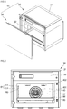
FIG. 1 is a perspective view illustrating an example oven in a state in which an example door of the oven is detached from the oven. -
FIG. 2 is a front view illustrating an example oven in a state in which a door is removed from the oven. -
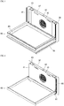
FIG. 3 is a perspective view illustrating an example cavity of an example oven in a state in which lateral walls and an upper wall are removed. -
FIG. 4 is a perspective view illustrating the example oven in a state in which a first tray, a corner frame, and a floor panel of the oven inFIG. 3 are removed. -
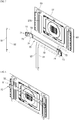
FIG. 5 is a perspective view illustrating the example oven in a state in which an example tray frame inFIG. 4 is detached. -
FIG. 6 is a perspective view illustrating the example oven in a state in which an example rear cover inFIG. 5 is removed. -
FIG. 7 is an exploded perspective view illustrating the example oven in a state in which an example ball screw and an example moving rack inFIG. 6 are detached. -
FIG. 8 is a perspective view illustrating the example oven in a state in which the moving rack is ascended by the ball screw inFIG. 6 . -
FIG. 9 is a perspective view illustrating an example ball nut built into the moving rack inFIG. 8 in a state in which a part of the moving rack is omitted. -
FIG. 10 is an enlarged plan view illustrating an example of a fixing member installed in the moving rack inFIG. 9 that is coupled to an example fixed tray rack. -
FIG. 11 is a perspective view illustrating an example additional tray frame that is installed at a fixed tray rack inFIG. 4 . -
FIG. 12 is a view illustrating an example structure for ascending and descending a tray in an oven in related art. - The present disclosure will be described with reference to exemplary implementations and attached drawings.
- The present disclosure may not be limited to the implementations described below, but may be implemented in various other forms. The implementations are presented so as to make the present disclosure thorough and complete and to convey the scope of the present disclosure to one having ordinary skill in the art completely.
- Referring to
FIGS. 1 to 3 , anexample oven 10 includes amain body 30 having acavity 32 that is a space for accommodating and heating food and adoor 20 provided at a front surface of themain body 30. Abody 31 of themain body 30 includes means such as a heater that heats food accommodated in thecavity 32, a fan, and the like, and thecavity 32 of thebody 31 has an approximate cu-boid-shaped space the front surface of which is open. - Various types of doors such as a pull-down door that swivels around a horizontal shaft of the lower portion of the door, a swing door that rotates around a perpendicular shaft of the left or the right of the door, and the like may be used as the
door 20. When thedoor 20 is closed, the front opening of thecavity 32 is closed, and the inside of thecavity 32 is sealed up. - The
cavity 32 includes afirst tray 88 therein so as to place food on the first tray, and thefirst tray 88 is placed on afirst tray frame 80 that may be drawn forward like a drawer. Accordingly, the user may open thedoor 20, draw thefirst tray frame 80, place food on thefirst tray 88 that is laid in thefirst tray frame 80 and put thefirst tray frame 80 into thecavity 32. - The
cavity 32 includes air holes that introduce air heated by a heater, on a rear wall thereof, and a fan at the rear of the air hole rotates, such that air heated by the heater is introduced through the air holes into thecavity 32. - The
body 31 of the main body includes anupper space 33 that accommodates a circuit board for controlling the operation of the oven, and the like in the upper portion of thecavity 32. - A structure for controlling a height of the
first tray 88 in thecavity 32 will be described. - An ascending/descending structure of a tray will be described with reference to
FIGS. 2 to 10 . - The cavity includes a
cavity floor panel 39 that defines a lower boundary surface of the cavity, on the bottom surface thereof and a cavityrear panel 37 that defines a rear boundary surface of the cavity, on the rear surface thereof. - The cavity
rear panel 37 includes acorner frame 38 that has a streamlined curve so as to allow air circulating in the cavity to smoothly flow, in both end portions thereof. Thecorner frame 38 includes a curved surface with an approximately concave arc-shaped profile, as illustrated in the drawings. - The
cavity floor panel 39 includes afirst tray frame 80 and afirst tray 88 in the upper portion thereof. Thefirst tray frame 80 is configured to be ascended and descended by a driving means or driving device such as a motor, and the like. In this disclosure, the driving means and a driving force delivering means arc provided at the rear of the cavity. - In some implementations, the driving means and the driving force delivering means may be located at the rear of a
rear cover 40. Therear cover 40 prevents the driving means and the driving force delivering means from being contaminated by foreign substances that pop while food is cooked, takes up little space in the cavity and induces heat circulating in the cavity to smoothly flow. - The
rear cover 40 is placed in parallel with the cavityrear panel 37 further forward than the cavityrear panel 37 and the rear cover is spaced a predetermined distance apart from the cavity rear panel by aspacer 42. Therear cover 40 may be integrally fixed to the cavityrear panel 37 by thespacer 42. When the cavityrear panel 37 is assembled to themain body 30 in the state where therear cover 40 is fixed to the cavityrear panel 37 by thespacer 42, the rear cover may be easily installed in the cavity. - The
rear cover 40 includes acentral air hole 401 that discharges heat from the rear of the rear cover, at the central portion thereof andperipheral air holes 402 provided around the central air hole. The central air hole and the peripheral air holes are provided in positions corresponding to those of acentral air hole 371 andperipheral air holes 372 in the cavityrear panel 37 so as to allow heat circulating via a fan at the rear of the cavityrear panel 37 to smoothly circulate. - The
rear cover 40 has an approximately rectangular plate shape. Therear cover 40 has a height corresponding to that of the cavityrear panel 37 and has a width narrower than that of the cavityrear panel 37. Both end portions of an ascending/descending rack 70 on which thefirst tray frame 80 may be laid are exposed on both front sides of the cavityrear panel 37 that are exposed due to a difference in the width of therear cover 40 and the cavityrear panel 37. - The ascending/
descending rack 70, which may be called as a moving rack, includes an upperfitting hole 711 that has the shape of a hole which is long in the up-down direction, in the upper portion of both end portions thereof and a lowerfitting hole 712 that has the shape of an approximately round hole in the lower portion of the upperfitting hole 711. The upperfitting hole 711 and the lowerfitting hole 712 constitutes a first trayframe connecting part 71 that connects with thefirst tray frame 80. A part, protruding further than therear cover 40 and exposed to the outside, of the ascending/descending rack 70 is the first trayframe connecting part 71. The first trayframe connecting part 71 may be a structure wherefitting holes rack member 75. - In some implementations, the
first tray frame 80 may have an approximate rectangular shape and include arack coupling part 81 that is detachably coupled to thefitting hole 710, in both rear end portions thereof. Therack coupling part 81 includes ahook 811 and aprotrusion 812 that extend backward, and thehook 811 is fitted into the upperfitting hole 711 while theprotrusion 812 is fitted into the lowerfitting hole 712. - When the
hook 811 is fitted into the upperfitting hole 711, and theprotrusion 812 is fitted into the lowerfitting hole 712, a hanger of the hook is held in the rear surface of the ascending/descending rack 70 via the self-weight of thefirst tray frame 80, and thefirst tray frame 80 remains horizontal in the shape of a cantilever. - The self-weight of the
first tray frame 80 and thefirst tray 88 that is placed in the first tray frame is applied as a moment to the first trayframe connecting part 71, and the present disclosure presents an ascending/descending structure that may support the moment properly so as to ascend and descend. The ascending/descending rack 70 is formed as across bar 72 that extends in the left-right direction, both end portions of which includes the first trayframe connecting part 71 respectively. Thecross bar 72 the central portion of which is open in the shape of a hole that is long in the left-right direction to the extent that interference with the flow of heat flowing through thecentral air hole 371 is minimized, that self-weight is reduced and that strength is maintained. Thecross bar 72 is placed close to the cavityrear panel 37 and takes up little space in the cavity. - The first tray
frame connecting part 71 is placed further forward than thecross bar 72. The first trayframe connecting part 71 is spaced apart from the cavityrear panel 37 further forward than thecross bar 72 so as to ensure a space at the rear of the first trayframe connecting part 71 and a space for the attachment and detachment of thefirst tray frame 80 and the first trayframe connecting part 71. - A first ascending/
descending connection part 73 is placed further inward than the first trayframe connecting part 71 in the left-lateral and right-lateral directions. The first ascending/descending connection part 73 is fitted into a first ascending/descendingguide part 51 that extends in the up-down direction. - A second ascending/
descending connection part 74 is placed further inward and further backward than the first ascending/descending connection part 73 in the left-lateral and right-lateral directions. The second ascending/descending connection part 74 is fitted into a second ascending/descendingguide part 52 that extends in the up-down direction. - The first ascending/
descending connection part 73 and the second ascending/descending connection part 74 are spaced a predetermined distance apart in the front-rear direction and, accordingly, effectively support a moment applied to the ascending/descending rack 70 via thefirst tray 88 that is installed as a cantilever structure. The first ascending/descending connection part and the second ascending/descending connection part are also spaced a predetermined distance apart in the left-right direction. Accordingly, the positions of the first ascending/descending connection part and the second asccnding/dcsccnding connection part may be partly overlapped in the front-rear direction. Thus, a distance between the first ascending/descending connection part and the second ascending/descending connection part may be shortened in the front-rear direction. - The ascending/
descending rack 70 is placed further backward than therear cover 40 so as not to interfere with the rear cover and placed further forward than the cavityrear panel 37 so as not to interfere with the cavity rear panel. That is, the ascending/descending rack 70 is placed between the rear cover and the cavityrear panel 37. When therear cover 40 is placed closer to the cavityrear panel 37, the inner space of thecavity 32 becomes greater. - The ascending/
descending rack 70 has the shape of a board that has a predetermined height and width and that stands. The first ascending/descending connection part 73 of the ascending/descending rack 70 is placed further forward than the second ascending/descending connection part 74 while not protruding further forward than the first trayframe connecting part 71, and the second ascending/descending connection part 74 is placed further backward than the first ascending/descending connection part 73 while not protruding further backward than thecross bar 72. - Specifically, in the ascending/
descending rack 70, abent part 77 where a board is bent is provided between thecross bar 72 and the first trayframe connecting part 71 such that the first tray frame connecting part is placed further forward than the cross bar, and the first ascending/descending connection part 73 may be placed further inward than the first trayframe connecting part 71 in the corner of a space that is ensured by thebent part 77 in the front-rear direction. When the first ascending/descending connection part 73 is placed in the corner of thebent part 77, a portion where the first ascending/descending connection part 73 adjoins the ascending/descending rack 70 becomes greater. - As an example structure for the ascending and descending of an ascending/
descending rack 70, a driving force of ascending and descending the ascending/descending rack 70 is separately delivered, and the first ascending/descending connection part 73 and the second ascending/descending connection part 74 may be configured to be guided by the first ascending/descendingguide part 51 and the second ascending/descendingguide part 52 so as to move upward and downward. - In the present disclosure, the first ascending/descending
guide part 51 and the second ascending/descendingguide part 52 are configured as a first ball screw and a second ball screw, and the first ascending/descending connection part 73 and the second ascending/descending connection part 74 are configured as a first ball nut and a second ball nut that are coupled to the first ball screw and second ball screw. Accordingly, thefirst ball screw 51 andsecond ball screw 52 rotate so as to drive and simultaneously guide the ascending and descending of the ascending/descending rack 70. The ascending and descending of the ascending/descending rack 70 may be driven and guided at the same time by the ball scrcws. Thus, an asccnding/dcsccnding structure of a tray may be easily implemented. - One end (e.g., an upper end) of the
first ball screw 51 andsecond ball screw 52 may be rotatably supported by asupport 53 provided in the cavityrear panel 37. The other end (lower end) of thefirst ball screw 51 andsecond ball screw 52 may be directly connected to the rotational shaft of a motor and supported or indirectly connected to the rotational shaft of a motor through a speed reducer, and the like and supported. - The first ball screw and the second ball screw on the left side may be configured to be rotated by one motor while the first ball screw and the second ball screw on the right side may be configured to be rotated by another motor.
- The
first ball screw 51 and thesecond ball screw 52 are supported by thesupport 53 fixed to the cavityrear panel 37, the ascending/descending rack 70 is supported by the first ascending/descendingguide part 51 and the second ascending/descendingguide part 52, and the rear panel is fixed to the cavity rear panel by a spacer. Accordingly, thefirst ball screw 51, thesecond ball screw 52, thesupport 53, the cavityrear panel 37, the first ascending/descendingguide part 51 and the second ascending/descendingguide part 52 are modularized so as to implement an ascending/descending structure. - The first ascending/descending
guide part 51 and the second ascending/descendingguide part 52 may not be affected by heated air because the first ascending/descendingguide part 51 and the second ascending/descendingguide part 52 are placed close to the first tray frame connecting part and away from the central air hole. - The lower portion of the ascending/
descending rack 70 may interfere with the cavityrear panel 37 via a moment applied by thefirst tray 88 in a way that pressurizes the front surface of the cavityrear panel 37 backward. - In some implementations, a first ascending/descending
guider 375 with the shape of a rail that extends in the up-down direction may be formed at the rear of a portion between the first ascending/descendingguide part 51 and the second ascending/descendingguide part 52, on the front surface of the cavity rear panel, and a second ascending/descendingguider 78 that has a groove shape, that contacts therail 375 and that is guided by the rail so as to ascend and descend may be formed on the rear surface of the ascending/descending rack 70. The additional guide structure is provided so as to guide upward and downward movements and to additionally apply a support structure of a moment that is applied to the ascending/descending rack 70 by thefirst tray 88, to the cavityrear panel 37. Accordingly, the additional guide structure may support thefirst tray 88 even when a heavy load of food is placed on thefirst tray 88 supported with a cantilever structure. The shape of the second ascending/descendingguider 78 is not limited to the shape of a groove that is placed in the rail and may further include a roller structure that can effectively support load acting in the front-rear direction and guide upward and backward movements, and the like. - The
rear cover 40 may further include aninclined surface part 43 corresponding to the structure of the ascending/descending rack 70, both end portions of which protrude forward because of thebent part 77. Therear cover 40 is placed close to thecross bar 72 of the ascending/descending rack 70 while both endportions 41 of the rear cover may protrude further forward than the rear cover through theinclined surface part 43 and may be placed close to the first trayframe connecting part 71. With the structure, a space for cooking food and a space for installing the ascending/descending rack 70 and ascending/descending guide parts (51, 52, 53, and the like) relating to the ascending/descending rack 70 may be separated, and maximization of space for cooking may be ensured. Additionally, theinclined surface part 43 allows heat in the cavity to flow smoothly. - The cavity
rear panel 37 further includes a fixedtray rack 60. The fixedtray rack 60 is fixed to the cavityrear panel 37 and provided with a plurality offitting holes 61 that are spaced a predetermined distance apart in the up-down direction. In the implementations, the fixed tray rack includes four fitting holes 61. - Each
fitting hole 61 includes an upperfitting hole 611 having the shape of a long hole that is open in the up-down direction and a lower fitting hole 612 having the shape of a round hole and provided in the lower portion of the upper fitting hole. The shapes of the upper and lower fitting holes may be substantially the same as those of the fitting holes 71 of the ascending/descending rack 70. - The
fitting hole 61 of the fixedtray rack 60 is also spaced a predetermined distance apart from the cavityrear panel 37. The fixedtray rack 60 is a structure in which asecond tray frame 90 of asecond tray 98 is additionally installed when two or more trays are installed in the cavity. - The
fitting hole 61 of the fixedtray rack 60 may be placed in a position corresponding to the position of thefitting hole 71 of the ascending/descending rack 70. In some examples, there may be a predetermined gap between members that include twofitting holes descending rack 70 and the first tray frame to be assembled. Accordingly, when a distance between left and right fitting holes 61 is matched with a distance between left and right fitting holes 71, the second tray and the second tray frame may be substantially the same as the first tray and the first tray frame. - The fixed
tray rack 60 may have a structure configured to support two or more tray frames 80, 90 installed in the cavity as shown inFIG. 11 . - In some implementations, the fixed
tray rack 60 has a structure where the ascending/descending rack 70 may be temporarily fixed. As shown inFIG. 10 , atemporary fixation member 76 such as a leaf spring is provided at the rear of thefitting hole 71 of the ascending/descending rack 70, and, when the ascending/descending rack 70 ascends to a predetermined height, and thetemporary fixation member 76 is fitted into thefitting hole 61, the ascending/descending rack 70 may stay stably in a position at the height. Thetemporary fixation member 76 may be installed not to interfere with arack coupling part 81 of the first tray frame. - In the above-described structure of the ascending/descending rack, structures such as the fixed
tray rack 60, the first trayframe connecting part 71, the ascending/descendingconnection parts Description of the Symbols 74: Second ball nut (second ascending/descending connection part) 10: Oven 20: Door 75: Rack member 30: Main body 76: Temporary fixation member 31: Body 77: Bent part 32: Cavity 78: Second ascending/descending guider (groove) 33: Upper space 37: Cavity rear panel 80: First tray frame 371: Central air hole 81: Rack coupling part 372: Peripheral air hole 811: Hook 375: First ascending/descending guider (rail) 812: Protrusion 38: Corner frame 88: First tray 39: Cavity floor panel 90: Second tray frame 40: Rear cover 91: Rack coupling part 401: Central air hole 98: Second tray 402: Peripheral air hole 41: Both end portions 42: Spacer 43: Inclined surface part (curved surface part) 50: Ascending/descending guide part 51: First ball screw (first ascending/descending guide part) 52: Second ball screw (second ascending/descending guide part) 53: Support 60: Fixed tray rack 61: Fitting hole (second tray frame connecting part) 611: Upper fitting hole 612: Lower fitting hole 70: Ascending/descending rack 710: Fitting hole (first tray frame connecting part) 711: Upper fitting hole 712: Lower fitting hole 72: Cross bar 73: First ball nut (first ascending/descending connection part)
Claims (15)
- An oven comprising:a cavity (32) for cooking food;a cavity rear panel (37) placed at a rear of the cavity (32); anda first tray (88) for being ascended/descended in the cavity (32),the oven further comprises:an ascending/descending guide part (50) installed at both lateral sides of the front surface of the cavity rear panel (37);an ascending/descending rack (70) including ascending/descending connection parts (73, 74) engaged with the ascending/descending guide part (50), the ascending/descending rack (70) is guided by the ascending/descending guide part (50) to ascend and descend;a first tray frame connecting part (71) provided to the ascending/descending rack (70);a first tray frame (80) coupled to the first tray (88), the first tray frame (80) is connected to the first tray frame connecting part (71); anda rear cover (40) placed between the first tray (88) and the cavity rear panel (37), characterized in that the rear cover (40) is provided at the front of the ascending/descending guide part (50) for shielding the ascending/descending guide part (50) and the ascending/descending connection parts (73, 74) from a space where the first tray (88) ascends and descends and that exposes the first tray frame connecting part (71) frontward.
- The oven of claim 1, wherein the first tray frame connecting part (71) is placed laterally further outward than the ascending/descending guide part (50).
- The oven of any one of precedent claims, wherein the ascending/descending guide part (50) comprises a ball screw that extends in the up-down direction,
the ascending/descending connection parts (73, 74) comprises a ball nut that is engaged with the ball screw,
one end of the ball screw is connected to a rotation driving means,
the other end of the ball screw is rotatably supported by a support (53). - The oven of claim 3, wherein the support (53) is fixed to the cavity rear panel (37).
- The oven of any one of precedent claims, wherein the ascending/descending guide part (50) comprises a first ascending/descending guide part (51) close to the first tray frame connecting part (71) laterally further inward than the first tray frame connecting part (71), and a second ascending/descending guide part (52) close to the first ascending/descending guide part (51),
the second ascending/descending guide part (52) is placed laterally further inward than the first ascending/descending guide part (51) and is placed further backward than the first ascending/descending guide part (51) in the front-rear direction. - The oven of claim 5, wherein the rear cover (40) comprises an inclined surface part (43) that obliquely extends forward and laterally outward and that covers the first ascending/descending guide part (51) and the second ascending/descending guide part (52).
- The oven of any one of precedent claims, wherein the first tray frame connecting parts (71) located on both sides of the ascending/descending rack (70) are connected by a cross bar (72) extending in the left-right direction, wherein the rear cover (40) covers a space where the cross bar (72) ascends and descends.
- The oven of any one of precedent claims, wherein the cavity rear panel (37) comprises air holes (371, 372), and the rear cover (40) comprises air holes (401, 402), wherein the air holes (401, 402) of the rear cover (40) are provided in positions corresponding to those of the air holes (371, 372) of the cavity rear panel (37).
- The oven of any one of precedent claims, wherein the rear cover (40) is fixed to the cavity rear panel (37) by a spacer (42).
- The oven of any one of precedent claims, wherein the cavity rear panel (37) comprises a first ascending/descending guider (375) that extends in the up-down direction, at a front surface thereof, wherein the ascending/descending rack (70) comprises a second ascending/descending guider (78) that is guided by the first ascending/descending guider (375) to ascend and descend.
- The oven of claim 10, wherein the first ascending/descending guider (375) is placed further backward than the ascending/descending guide part (50).
- The oven of any one of precedent claims, wherein the first tray frame connecting part (71) is spaced a predetermined distance apart forward from the cavity rear panel (37),
a fixed tray rack (60) is provided between the cavity rear panel (37) and the first tray frame connecting part (71). - The oven of claim 12, wherein the fixed tray rack (60) is fixed to the cavity rear panel (37) and is spaced apart from the cavity rear panel (37) and the first tray frame connecting part (71).
- The oven of claim 12 or 13, wherein the fixed tray rack (60) comprises a second tray frame connecting part (61) that detachably connects with a second tray frame (90), in predetermined positions thereof that are spaced apart in the up-down direction.
- The oven of claim 14, wherein the second tray frame connecting part (61) has a hole shape, the first tray frame connecting part (71) of the ascending/descending rack (70) comprises a temporary fixation member (76) that is temporarily coupled to the second tray frame connecting part (61), at a rear thereof.
Applications Claiming Priority (1)
| Application Number | Priority Date | Filing Date | Title |
|---|---|---|---|
| KR1020180025025A KR102047305B1 (en) | 2018-03-02 | 2018-03-02 | An Oven Equipped with Auto-ElevatingTray |
Publications (2)
| Publication Number | Publication Date |
|---|---|
| EP3534072A1 EP3534072A1 (en) | 2019-09-04 |
| EP3534072B1 true EP3534072B1 (en) | 2021-04-07 |
Family
ID=65657262
Family Applications (1)
| Application Number | Title | Priority Date | Filing Date |
|---|---|---|---|
| EP19160053.5A Active EP3534072B1 (en) | 2018-03-02 | 2019-02-28 | Oven equipped with automatically ascending/descending tray |
Country Status (3)
| Country | Link |
|---|---|
| US (1) | US10941946B2 (en) |
| EP (1) | EP3534072B1 (en) |
| KR (1) | KR102047305B1 (en) |
Families Citing this family (6)
| Publication number | Priority date | Publication date | Assignee | Title |
|---|---|---|---|---|
| USD945824S1 (en) * | 2019-06-25 | 2022-03-15 | Lg Electronics Inc. | Oven range |
| USD980013S1 (en) | 2019-06-28 | 2023-03-07 | Whirlpool Corporation | Cooking appliance |
| US11339971B2 (en) * | 2019-09-13 | 2022-05-24 | Guangdong Midea Kitchen Appliances Manufacturing Co., Ltd. | Oven with automatic control of pan elevation |
| USD1041349S1 (en) * | 2021-12-13 | 2024-09-10 | Lg Electronics Inc. | Tray for indoor plant cultivator |
| US20250297744A1 (en) * | 2024-03-22 | 2025-09-25 | Whirlpool Corporation | Cooking appliance having a support rack |
| KR20260054193A (en) | 2024-10-15 | 2026-04-22 | 타이 파운틴 오브 라이프 씨오.,엘티디. | Home appliance back panel inversion device |
Family Cites Families (21)
| Publication number | Priority date | Publication date | Assignee | Title |
|---|---|---|---|---|
| US2919691A (en) * | 1955-08-22 | 1960-01-05 | Moffats Ltd | Mechanism for adjusting the height of racks in range ovens |
| US3059634A (en) * | 1960-01-20 | 1962-10-23 | Susan B Brinkman | Power operated oven rack |
| US3043290A (en) * | 1961-03-01 | 1962-07-10 | Moffats Ltd | Oven rack elevating and lowering mechanism |
| US3976000A (en) * | 1975-02-27 | 1976-08-24 | The Hoover Company | Rotatable and vertically adjustable rack |
| JPS597878Y2 (en) * | 1980-09-11 | 1984-03-10 | タイガー魔法瓶株式会社 | table grill |
| JPS5754332A (en) | 1980-09-19 | 1982-03-31 | Nec Corp | Forming method for thermonitride silicon film |
| US5429043A (en) * | 1994-10-24 | 1995-07-04 | Becker; Ruby | Power operated adjustable oven rack |
| KR970010476A (en) | 1995-08-31 | 1997-03-27 | 한승준 | Parking brake lever |
| KR970010476U (en) | 1995-08-31 | 1997-03-29 | Shelf height automatic adjustment device of gas oven | |
| US5938959A (en) * | 1998-04-07 | 1999-08-17 | Testrite Baparoma International Llc | Oven with automatically movable shelf |
| DE102004042827B4 (en) * | 2004-08-27 | 2011-05-05 | E.G.O. Elektro-Gerätebau GmbH | Oven and method for operating the same |
| ES2343229B1 (en) * | 2007-07-13 | 2011-07-19 | Teka Industrial, S.A. | OVEN WITH AUTOMATIC SYSTEM OF VERTICAL DISPLACEMENT OF TRAYS. |
| KR101617283B1 (en) * | 2009-05-04 | 2016-05-02 | 엘지전자 주식회사 | Cooker and Control method of the same |
| EP2748536A1 (en) * | 2011-08-22 | 2014-07-02 | Arçelik Anonim Sirketi | An oven comprising a movable support |
| US9297539B2 (en) * | 2012-07-27 | 2016-03-29 | Ssw Holding Company, Inc. | Assembly for attachment to rear wall of appliance cavity |
| US9109804B2 (en) * | 2013-02-25 | 2015-08-18 | General Electric Company | Appliance with vertically adjustable rack |
| KR20150141797A (en) | 2014-06-10 | 2015-12-21 | 삼성전자주식회사 | Oven |
| KR101688740B1 (en) | 2015-08-13 | 2016-12-22 | 오종찬 | Knee support with hold for conclusion |
| WO2017102247A1 (en) * | 2015-12-18 | 2017-06-22 | BSH Hausgeräte GmbH | An oven having an adjustable height rack assembly |
| KR102475320B1 (en) * | 2016-04-26 | 2022-12-08 | 삼성전자주식회사 | Electric oven |
| EP3276264A1 (en) * | 2016-07-29 | 2018-01-31 | Apparatebau Gronbach Srl | Motion device for a kitchen appliance, and kitchen appliance having such a motion device |
-
2018
- 2018-03-02 KR KR1020180025025A patent/KR102047305B1/en active Active
-
2019
- 2019-02-28 EP EP19160053.5A patent/EP3534072B1/en active Active
- 2019-03-01 US US16/290,143 patent/US10941946B2/en active Active
Also Published As
| Publication number | Publication date |
|---|---|
| KR20190104667A (en) | 2019-09-11 |
| EP3534072A1 (en) | 2019-09-04 |
| KR102047305B1 (en) | 2019-11-21 |
| US10941946B2 (en) | 2021-03-09 |
| US20190271475A1 (en) | 2019-09-05 |
Similar Documents
| Publication | Publication Date | Title |
|---|---|---|
| EP3534072A1 (en) | Oven equipped with automatically ascending/descending tray | |
| CN110455036B (en) | Refrigerator with a door | |
| KR102842624B1 (en) | Refrigerator | |
| US20080309211A1 (en) | Ovens | |
| KR101617283B1 (en) | Cooker and Control method of the same | |
| KR102790991B1 (en) | Refrigerator | |
| KR20190120881A (en) | An Oven Equipped with Easy-Elevating Tray | |
| CN112229129B (en) | Refrigerator and control method thereof | |
| TWI477247B (en) | Kitchen with lift hanging cabinet | |
| KR20100040868A (en) | Liftable suspended cupboard | |
| CN101336354B (en) | Modification for oven | |
| EP1532403B1 (en) | Shelf arrangement for ovens | |
| KR101683085B1 (en) | Cauldron type induction cooker using electromagnetic induction device | |
| US4400045A (en) | Built-in kitchen unit | |
| US4397508A (en) | Built-in baking and roasting oven | |
| CN213721501U (en) | Air frying and baking oven | |
| CN213248553U (en) | oven | |
| CN211634440U (en) | Disinfection cabinet with lifting device | |
| CN222533091U (en) | Steaming and baking oven and integrated kitchen range comprising automatic lifting mechanism | |
| CN210399030U (en) | Stove lifting mechanism | |
| CN215190270U (en) | Household appliance with door body | |
| JP4835373B2 (en) | Kitchen equipment | |
| CN219692858U (en) | Hanging device of wall-mounted electric appliance and wall-mounted electric appliance | |
| CN213721500U (en) | Air frying and baking box with baking fork | |
| KR20260011881A (en) | Food supplying table with integrated automatic lift |
Legal Events
| Date | Code | Title | Description |
|---|---|---|---|
| PUAI | Public reference made under article 153(3) epc to a published international application that has entered the european phase |
Free format text: ORIGINAL CODE: 0009012 |
|
| STAA | Information on the status of an ep patent application or granted ep patent |
Free format text: STATUS: REQUEST FOR EXAMINATION WAS MADE |
|
| 17P | Request for examination filed |
Effective date: 20190228 |
|
| AK | Designated contracting states |
Kind code of ref document: A1 Designated state(s): AL AT BE BG CH CY CZ DE DK EE ES FI FR GB GR HR HU IE IS IT LI LT LU LV MC MK MT NL NO PL PT RO RS SE SI SK SM TR |
|
| AX | Request for extension of the european patent |
Extension state: BA ME |
|
| RBV | Designated contracting states (corrected) |
Designated state(s): AL AT BE BG CH CY CZ DE DK EE ES FI FR GB GR HR HU IE IS IT LI LT LU LV MC MK MT NL NO PL PT RO RS SE SI SK SM TR |
|
| GRAP | Despatch of communication of intention to grant a patent |
Free format text: ORIGINAL CODE: EPIDOSNIGR1 |
|
| STAA | Information on the status of an ep patent application or granted ep patent |
Free format text: STATUS: GRANT OF PATENT IS INTENDED |
|
| INTG | Intention to grant announced |
Effective date: 20201012 |
|
| GRAS | Grant fee paid |
Free format text: ORIGINAL CODE: EPIDOSNIGR3 |
|
| GRAA | (expected) grant |
Free format text: ORIGINAL CODE: 0009210 |
|
| STAA | Information on the status of an ep patent application or granted ep patent |
Free format text: STATUS: THE PATENT HAS BEEN GRANTED |
|
| AK | Designated contracting states |
Kind code of ref document: B1 Designated state(s): AL AT BE BG CH CY CZ DE DK EE ES FI FR GB GR HR HU IE IS IT LI LT LU LV MC MK MT NL NO PL PT RO RS SE SI SK SM TR |
|
| REG | Reference to a national code |
Ref country code: GB Ref legal event code: FG4D |
|
| REG | Reference to a national code |
Ref country code: AT Ref legal event code: REF Ref document number: 1380171 Country of ref document: AT Kind code of ref document: T Effective date: 20210415 Ref country code: CH Ref legal event code: EP |
|
| REG | Reference to a national code |
Ref country code: DE Ref legal event code: R096 Ref document number: 602019003673 Country of ref document: DE |
|
| REG | Reference to a national code |
Ref country code: IE Ref legal event code: FG4D |
|
| REG | Reference to a national code |
Ref country code: LT Ref legal event code: MG9D |
|
| REG | Reference to a national code |
Ref country code: NL Ref legal event code: MP Effective date: 20210407 Ref country code: AT Ref legal event code: MK05 Ref document number: 1380171 Country of ref document: AT Kind code of ref document: T Effective date: 20210407 |
|
| PG25 | Lapsed in a contracting state [announced via postgrant information from national office to epo] |
Ref country code: FI Free format text: LAPSE BECAUSE OF FAILURE TO SUBMIT A TRANSLATION OF THE DESCRIPTION OR TO PAY THE FEE WITHIN THE PRESCRIBED TIME-LIMIT Effective date: 20210407 Ref country code: HR Free format text: LAPSE BECAUSE OF FAILURE TO SUBMIT A TRANSLATION OF THE DESCRIPTION OR TO PAY THE FEE WITHIN THE PRESCRIBED TIME-LIMIT Effective date: 20210407 Ref country code: LT Free format text: LAPSE BECAUSE OF FAILURE TO SUBMIT A TRANSLATION OF THE DESCRIPTION OR TO PAY THE FEE WITHIN THE PRESCRIBED TIME-LIMIT Effective date: 20210407 Ref country code: NL Free format text: LAPSE BECAUSE OF FAILURE TO SUBMIT A TRANSLATION OF THE DESCRIPTION OR TO PAY THE FEE WITHIN THE PRESCRIBED TIME-LIMIT Effective date: 20210407 Ref country code: AT Free format text: LAPSE BECAUSE OF FAILURE TO SUBMIT A TRANSLATION OF THE DESCRIPTION OR TO PAY THE FEE WITHIN THE PRESCRIBED TIME-LIMIT Effective date: 20210407 Ref country code: BG Free format text: LAPSE BECAUSE OF FAILURE TO SUBMIT A TRANSLATION OF THE DESCRIPTION OR TO PAY THE FEE WITHIN THE PRESCRIBED TIME-LIMIT Effective date: 20210707 |
|
| PG25 | Lapsed in a contracting state [announced via postgrant information from national office to epo] |
Ref country code: PL Free format text: LAPSE BECAUSE OF FAILURE TO SUBMIT A TRANSLATION OF THE DESCRIPTION OR TO PAY THE FEE WITHIN THE PRESCRIBED TIME-LIMIT Effective date: 20210407 Ref country code: LV Free format text: LAPSE BECAUSE OF FAILURE TO SUBMIT A TRANSLATION OF THE DESCRIPTION OR TO PAY THE FEE WITHIN THE PRESCRIBED TIME-LIMIT Effective date: 20210407 Ref country code: NO Free format text: LAPSE BECAUSE OF FAILURE TO SUBMIT A TRANSLATION OF THE DESCRIPTION OR TO PAY THE FEE WITHIN THE PRESCRIBED TIME-LIMIT Effective date: 20210707 Ref country code: RS Free format text: LAPSE BECAUSE OF FAILURE TO SUBMIT A TRANSLATION OF THE DESCRIPTION OR TO PAY THE FEE WITHIN THE PRESCRIBED TIME-LIMIT Effective date: 20210407 Ref country code: PT Free format text: LAPSE BECAUSE OF FAILURE TO SUBMIT A TRANSLATION OF THE DESCRIPTION OR TO PAY THE FEE WITHIN THE PRESCRIBED TIME-LIMIT Effective date: 20210809 Ref country code: SE Free format text: LAPSE BECAUSE OF FAILURE TO SUBMIT A TRANSLATION OF THE DESCRIPTION OR TO PAY THE FEE WITHIN THE PRESCRIBED TIME-LIMIT Effective date: 20210407 Ref country code: GR Free format text: LAPSE BECAUSE OF FAILURE TO SUBMIT A TRANSLATION OF THE DESCRIPTION OR TO PAY THE FEE WITHIN THE PRESCRIBED TIME-LIMIT Effective date: 20210708 Ref country code: IS Free format text: LAPSE BECAUSE OF FAILURE TO SUBMIT A TRANSLATION OF THE DESCRIPTION OR TO PAY THE FEE WITHIN THE PRESCRIBED TIME-LIMIT Effective date: 20210807 |
|
| REG | Reference to a national code |
Ref country code: DE Ref legal event code: R097 Ref document number: 602019003673 Country of ref document: DE |
|
| PG25 | Lapsed in a contracting state [announced via postgrant information from national office to epo] |
Ref country code: ES Free format text: LAPSE BECAUSE OF FAILURE TO SUBMIT A TRANSLATION OF THE DESCRIPTION OR TO PAY THE FEE WITHIN THE PRESCRIBED TIME-LIMIT Effective date: 20210407 Ref country code: EE Free format text: LAPSE BECAUSE OF FAILURE TO SUBMIT A TRANSLATION OF THE DESCRIPTION OR TO PAY THE FEE WITHIN THE PRESCRIBED TIME-LIMIT Effective date: 20210407 Ref country code: SK Free format text: LAPSE BECAUSE OF FAILURE TO SUBMIT A TRANSLATION OF THE DESCRIPTION OR TO PAY THE FEE WITHIN THE PRESCRIBED TIME-LIMIT Effective date: 20210407 Ref country code: SM Free format text: LAPSE BECAUSE OF FAILURE TO SUBMIT A TRANSLATION OF THE DESCRIPTION OR TO PAY THE FEE WITHIN THE PRESCRIBED TIME-LIMIT Effective date: 20210407 Ref country code: RO Free format text: LAPSE BECAUSE OF FAILURE TO SUBMIT A TRANSLATION OF THE DESCRIPTION OR TO PAY THE FEE WITHIN THE PRESCRIBED TIME-LIMIT Effective date: 20210407 Ref country code: DK Free format text: LAPSE BECAUSE OF FAILURE TO SUBMIT A TRANSLATION OF THE DESCRIPTION OR TO PAY THE FEE WITHIN THE PRESCRIBED TIME-LIMIT Effective date: 20210407 Ref country code: CZ Free format text: LAPSE BECAUSE OF FAILURE TO SUBMIT A TRANSLATION OF THE DESCRIPTION OR TO PAY THE FEE WITHIN THE PRESCRIBED TIME-LIMIT Effective date: 20210407 |
|
| PLBE | No opposition filed within time limit |
Free format text: ORIGINAL CODE: 0009261 |
|
| STAA | Information on the status of an ep patent application or granted ep patent |
Free format text: STATUS: NO OPPOSITION FILED WITHIN TIME LIMIT |
|
| 26N | No opposition filed |
Effective date: 20220110 |
|
| PG25 | Lapsed in a contracting state [announced via postgrant information from national office to epo] |
Ref country code: IS Free format text: LAPSE BECAUSE OF FAILURE TO SUBMIT A TRANSLATION OF THE DESCRIPTION OR TO PAY THE FEE WITHIN THE PRESCRIBED TIME-LIMIT Effective date: 20210807 Ref country code: AL Free format text: LAPSE BECAUSE OF FAILURE TO SUBMIT A TRANSLATION OF THE DESCRIPTION OR TO PAY THE FEE WITHIN THE PRESCRIBED TIME-LIMIT Effective date: 20210407 |
|
| PG25 | Lapsed in a contracting state [announced via postgrant information from national office to epo] |
Ref country code: IT Free format text: LAPSE BECAUSE OF FAILURE TO SUBMIT A TRANSLATION OF THE DESCRIPTION OR TO PAY THE FEE WITHIN THE PRESCRIBED TIME-LIMIT Effective date: 20210407 |
|
| PG25 | Lapsed in a contracting state [announced via postgrant information from national office to epo] |
Ref country code: MC Free format text: LAPSE BECAUSE OF FAILURE TO SUBMIT A TRANSLATION OF THE DESCRIPTION OR TO PAY THE FEE WITHIN THE PRESCRIBED TIME-LIMIT Effective date: 20210407 |
|
| REG | Reference to a national code |
Ref country code: CH Ref legal event code: PL |
|
| REG | Reference to a national code |
Ref country code: BE Ref legal event code: MM Effective date: 20220228 |
|
| PG25 | Lapsed in a contracting state [announced via postgrant information from national office to epo] |
Ref country code: LU Free format text: LAPSE BECAUSE OF NON-PAYMENT OF DUE FEES Effective date: 20220228 |
|
| PG25 | Lapsed in a contracting state [announced via postgrant information from national office to epo] |
Ref country code: FR Free format text: LAPSE BECAUSE OF NON-PAYMENT OF DUE FEES Effective date: 20220228 |
|
| PG25 | Lapsed in a contracting state [announced via postgrant information from national office to epo] |
Ref country code: LI Free format text: LAPSE BECAUSE OF NON-PAYMENT OF DUE FEES Effective date: 20220228 Ref country code: IE Free format text: LAPSE BECAUSE OF NON-PAYMENT OF DUE FEES Effective date: 20220228 Ref country code: CH Free format text: LAPSE BECAUSE OF NON-PAYMENT OF DUE FEES Effective date: 20220228 |
|
| PG25 | Lapsed in a contracting state [announced via postgrant information from national office to epo] |
Ref country code: BE Free format text: LAPSE BECAUSE OF NON-PAYMENT OF DUE FEES Effective date: 20220228 |
|
| GBPC | Gb: european patent ceased through non-payment of renewal fee |
Effective date: 20230228 |
|
| PG25 | Lapsed in a contracting state [announced via postgrant information from national office to epo] |
Ref country code: GB Free format text: LAPSE BECAUSE OF NON-PAYMENT OF DUE FEES Effective date: 20230228 |
|
| PG25 | Lapsed in a contracting state [announced via postgrant information from national office to epo] |
Ref country code: GB Free format text: LAPSE BECAUSE OF NON-PAYMENT OF DUE FEES Effective date: 20230228 |
|
| PG25 | Lapsed in a contracting state [announced via postgrant information from national office to epo] |
Ref country code: MK Free format text: LAPSE BECAUSE OF FAILURE TO SUBMIT A TRANSLATION OF THE DESCRIPTION OR TO PAY THE FEE WITHIN THE PRESCRIBED TIME-LIMIT Effective date: 20210407 Ref country code: CY Free format text: LAPSE BECAUSE OF FAILURE TO SUBMIT A TRANSLATION OF THE DESCRIPTION OR TO PAY THE FEE WITHIN THE PRESCRIBED TIME-LIMIT Effective date: 20210407 |
|
| PG25 | Lapsed in a contracting state [announced via postgrant information from national office to epo] |
Ref country code: HU Free format text: LAPSE BECAUSE OF FAILURE TO SUBMIT A TRANSLATION OF THE DESCRIPTION OR TO PAY THE FEE WITHIN THE PRESCRIBED TIME-LIMIT; INVALID AB INITIO Effective date: 20190228 |
|
| PG25 | Lapsed in a contracting state [announced via postgrant information from national office to epo] |
Ref country code: TR Free format text: LAPSE BECAUSE OF FAILURE TO SUBMIT A TRANSLATION OF THE DESCRIPTION OR TO PAY THE FEE WITHIN THE PRESCRIBED TIME-LIMIT Effective date: 20210407 |
|
| PG25 | Lapsed in a contracting state [announced via postgrant information from national office to epo] |
Ref country code: MT Free format text: LAPSE BECAUSE OF FAILURE TO SUBMIT A TRANSLATION OF THE DESCRIPTION OR TO PAY THE FEE WITHIN THE PRESCRIBED TIME-LIMIT Effective date: 20210407 |
|
| PGFP | Annual fee paid to national office [announced via postgrant information from national office to epo] |
Ref country code: DE Payment date: 20260105 Year of fee payment: 8 |