EP3534071A1 - Fastener assembly having a leak resistant threaded insert - Google Patents
Fastener assembly having a leak resistant threaded insert Download PDFInfo
- Publication number
- EP3534071A1 EP3534071A1 EP19160138.4A EP19160138A EP3534071A1 EP 3534071 A1 EP3534071 A1 EP 3534071A1 EP 19160138 A EP19160138 A EP 19160138A EP 3534071 A1 EP3534071 A1 EP 3534071A1
- Authority
- EP
- European Patent Office
- Prior art keywords
- insert
- fastener
- leak resistant
- inner threaded
- section
- Prior art date
- Legal status (The legal status is an assumption and is not a legal conclusion. Google has not performed a legal analysis and makes no representation as to the accuracy of the status listed.)
- Granted
Links
Images




Classifications
-
- F—MECHANICAL ENGINEERING; LIGHTING; HEATING; WEAPONS; BLASTING
- F16—ENGINEERING ELEMENTS AND UNITS; GENERAL MEASURES FOR PRODUCING AND MAINTAINING EFFECTIVE FUNCTIONING OF MACHINES OR INSTALLATIONS; THERMAL INSULATION IN GENERAL
- F16B—DEVICES FOR FASTENING OR SECURING CONSTRUCTIONAL ELEMENTS OR MACHINE PARTS TOGETHER, e.g. NAILS, BOLTS, CIRCLIPS, CLAMPS, CLIPS OR WEDGES; JOINTS OR JOINTING
- F16B43/00—Washers or equivalent devices; Other devices for supporting bolt-heads or nuts
- F16B43/001—Washers or equivalent devices; Other devices for supporting bolt-heads or nuts for sealing or insulation
-
- F—MECHANICAL ENGINEERING; LIGHTING; HEATING; WEAPONS; BLASTING
- F01—MACHINES OR ENGINES IN GENERAL; ENGINE PLANTS IN GENERAL; STEAM ENGINES
- F01D—NON-POSITIVE DISPLACEMENT MACHINES OR ENGINES, e.g. STEAM TURBINES
- F01D11/00—Preventing or minimising internal leakage of working-fluid, e.g. between stages
- F01D11/005—Sealing means between non relatively rotating elements
-
- F—MECHANICAL ENGINEERING; LIGHTING; HEATING; WEAPONS; BLASTING
- F01—MACHINES OR ENGINES IN GENERAL; ENGINE PLANTS IN GENERAL; STEAM ENGINES
- F01D—NON-POSITIVE DISPLACEMENT MACHINES OR ENGINES, e.g. STEAM TURBINES
- F01D25/00—Component parts, details, or accessories, not provided for in, or of interest apart from, other groups
- F01D25/24—Casings; Casing parts, e.g. diaphragms, casing fastenings
- F01D25/243—Flange connections; Bolting arrangements
-
- F—MECHANICAL ENGINEERING; LIGHTING; HEATING; WEAPONS; BLASTING
- F16—ENGINEERING ELEMENTS AND UNITS; GENERAL MEASURES FOR PRODUCING AND MAINTAINING EFFECTIVE FUNCTIONING OF MACHINES OR INSTALLATIONS; THERMAL INSULATION IN GENERAL
- F16B—DEVICES FOR FASTENING OR SECURING CONSTRUCTIONAL ELEMENTS OR MACHINE PARTS TOGETHER, e.g. NAILS, BOLTS, CIRCLIPS, CLAMPS, CLIPS OR WEDGES; JOINTS OR JOINTING
- F16B33/00—Features common to bolt and nut
- F16B33/004—Sealing; Insulation
-
- F—MECHANICAL ENGINEERING; LIGHTING; HEATING; WEAPONS; BLASTING
- F23—COMBUSTION APPARATUS; COMBUSTION PROCESSES
- F23R—GENERATING COMBUSTION PRODUCTS OF HIGH PRESSURE OR HIGH VELOCITY, e.g. GAS-TURBINE COMBUSTION CHAMBERS
- F23R3/00—Continuous combustion chambers using liquid or gaseous fuel
- F23R3/42—Continuous combustion chambers using liquid or gaseous fuel characterised by the arrangement or form of the flame tubes or combustion chambers
- F23R3/60—Support structures; Attaching or mounting means
-
- F—MECHANICAL ENGINEERING; LIGHTING; HEATING; WEAPONS; BLASTING
- F01—MACHINES OR ENGINES IN GENERAL; ENGINE PLANTS IN GENERAL; STEAM ENGINES
- F01D—NON-POSITIVE DISPLACEMENT MACHINES OR ENGINES, e.g. STEAM TURBINES
- F01D25/00—Component parts, details, or accessories, not provided for in, or of interest apart from, other groups
- F01D25/28—Supporting or mounting arrangements, e.g. for turbine casing
-
- F—MECHANICAL ENGINEERING; LIGHTING; HEATING; WEAPONS; BLASTING
- F04—POSITIVE - DISPLACEMENT MACHINES FOR LIQUIDS; PUMPS FOR LIQUIDS OR ELASTIC FLUIDS
- F04D—NON-POSITIVE-DISPLACEMENT PUMPS
- F04D29/00—Details, component parts, or accessories
- F04D29/60—Mounting; Assembling; Disassembling
- F04D29/601—Mounting; Assembling; Disassembling specially adapted for elastic fluid pumps
-
- F—MECHANICAL ENGINEERING; LIGHTING; HEATING; WEAPONS; BLASTING
- F05—INDEXING SCHEMES RELATING TO ENGINES OR PUMPS IN VARIOUS SUBCLASSES OF CLASSES F01-F04
- F05D—INDEXING SCHEME FOR ASPECTS RELATING TO NON-POSITIVE-DISPLACEMENT MACHINES OR ENGINES, GAS-TURBINES OR JET-PROPULSION PLANTS
- F05D2220/00—Application
- F05D2220/30—Application in turbines
- F05D2220/32—Application in turbines in gas turbines
- F05D2220/323—Application in turbines in gas turbines for aircraft propulsion, e.g. jet engines
-
- F—MECHANICAL ENGINEERING; LIGHTING; HEATING; WEAPONS; BLASTING
- F05—INDEXING SCHEMES RELATING TO ENGINES OR PUMPS IN VARIOUS SUBCLASSES OF CLASSES F01-F04
- F05D—INDEXING SCHEME FOR ASPECTS RELATING TO NON-POSITIVE-DISPLACEMENT MACHINES OR ENGINES, GAS-TURBINES OR JET-PROPULSION PLANTS
- F05D2240/00—Components
- F05D2240/10—Stators
- F05D2240/14—Casings or housings protecting or supporting assemblies within
-
- F—MECHANICAL ENGINEERING; LIGHTING; HEATING; WEAPONS; BLASTING
- F05—INDEXING SCHEMES RELATING TO ENGINES OR PUMPS IN VARIOUS SUBCLASSES OF CLASSES F01-F04
- F05D—INDEXING SCHEME FOR ASPECTS RELATING TO NON-POSITIVE-DISPLACEMENT MACHINES OR ENGINES, GAS-TURBINES OR JET-PROPULSION PLANTS
- F05D2240/00—Components
- F05D2240/55—Seals
-
- F—MECHANICAL ENGINEERING; LIGHTING; HEATING; WEAPONS; BLASTING
- F05—INDEXING SCHEMES RELATING TO ENGINES OR PUMPS IN VARIOUS SUBCLASSES OF CLASSES F01-F04
- F05D—INDEXING SCHEME FOR ASPECTS RELATING TO NON-POSITIVE-DISPLACEMENT MACHINES OR ENGINES, GAS-TURBINES OR JET-PROPULSION PLANTS
- F05D2260/00—Function
- F05D2260/30—Retaining components in desired mutual position
- F05D2260/31—Retaining bolts or nuts
-
- F—MECHANICAL ENGINEERING; LIGHTING; HEATING; WEAPONS; BLASTING
- F05—INDEXING SCHEMES RELATING TO ENGINES OR PUMPS IN VARIOUS SUBCLASSES OF CLASSES F01-F04
- F05D—INDEXING SCHEME FOR ASPECTS RELATING TO NON-POSITIVE-DISPLACEMENT MACHINES OR ENGINES, GAS-TURBINES OR JET-PROPULSION PLANTS
- F05D2260/00—Function
- F05D2260/30—Retaining components in desired mutual position
- F05D2260/37—Retaining components in desired mutual position by a press fit connection
-
- F—MECHANICAL ENGINEERING; LIGHTING; HEATING; WEAPONS; BLASTING
- F16—ENGINEERING ELEMENTS AND UNITS; GENERAL MEASURES FOR PRODUCING AND MAINTAINING EFFECTIVE FUNCTIONING OF MACHINES OR INSTALLATIONS; THERMAL INSULATION IN GENERAL
- F16B—DEVICES FOR FASTENING OR SECURING CONSTRUCTIONAL ELEMENTS OR MACHINE PARTS TOGETHER, e.g. NAILS, BOLTS, CIRCLIPS, CLAMPS, CLIPS OR WEDGES; JOINTS OR JOINTING
- F16B37/00—Nuts or like thread-engaging members
- F16B2037/007—Nuts or like thread-engaging members with a blind hole
-
- F—MECHANICAL ENGINEERING; LIGHTING; HEATING; WEAPONS; BLASTING
- F16—ENGINEERING ELEMENTS AND UNITS; GENERAL MEASURES FOR PRODUCING AND MAINTAINING EFFECTIVE FUNCTIONING OF MACHINES OR INSTALLATIONS; THERMAL INSULATION IN GENERAL
- F16B—DEVICES FOR FASTENING OR SECURING CONSTRUCTIONAL ELEMENTS OR MACHINE PARTS TOGETHER, e.g. NAILS, BOLTS, CIRCLIPS, CLAMPS, CLIPS OR WEDGES; JOINTS OR JOINTING
- F16B5/00—Joining sheets or plates, e.g. panels, to one another or to strips or bars parallel to them
- F16B5/02—Joining sheets or plates, e.g. panels, to one another or to strips or bars parallel to them by means of fastening members using screw-thread
-
- F—MECHANICAL ENGINEERING; LIGHTING; HEATING; WEAPONS; BLASTING
- F16—ENGINEERING ELEMENTS AND UNITS; GENERAL MEASURES FOR PRODUCING AND MAINTAINING EFFECTIVE FUNCTIONING OF MACHINES OR INSTALLATIONS; THERMAL INSULATION IN GENERAL
- F16B—DEVICES FOR FASTENING OR SECURING CONSTRUCTIONAL ELEMENTS OR MACHINE PARTS TOGETHER, e.g. NAILS, BOLTS, CIRCLIPS, CLAMPS, CLIPS OR WEDGES; JOINTS OR JOINTING
- F16B5/00—Joining sheets or plates, e.g. panels, to one another or to strips or bars parallel to them
- F16B5/06—Joining sheets or plates, e.g. panels, to one another or to strips or bars parallel to them by means of clamps or clips
- F16B5/0607—Joining sheets or plates, e.g. panels, to one another or to strips or bars parallel to them by means of clamps or clips joining sheets or plates to each other
- F16B5/0621—Joining sheets or plates, e.g. panels, to one another or to strips or bars parallel to them by means of clamps or clips joining sheets or plates to each other in parallel relationship
- F16B5/065—Joining sheets or plates, e.g. panels, to one another or to strips or bars parallel to them by means of clamps or clips joining sheets or plates to each other in parallel relationship the plates being one on top of the other and distanced from each other, e.g. by using protrusions to keep contact and distance
-
- F—MECHANICAL ENGINEERING; LIGHTING; HEATING; WEAPONS; BLASTING
- F23—COMBUSTION APPARATUS; COMBUSTION PROCESSES
- F23R—GENERATING COMBUSTION PRODUCTS OF HIGH PRESSURE OR HIGH VELOCITY, e.g. GAS-TURBINE COMBUSTION CHAMBERS
- F23R2900/00—Special features of, or arrangements for continuous combustion chambers; Combustion processes therefor
- F23R2900/00017—Assembling combustion chamber liners or subparts
Definitions
- the present disclosure relates generally to gas turbine engines, and more specifically, to a fastener assembly having a leak resistant threaded insert for use in mounting components in gas turbine engines.
- Gas turbine engines typically include a fan section, a compressor section, a combustor section and a turbine section.
- a fan section may drive air along a bypass flowpath while a compressor section may drive air along a core flowpath.
- air is pressurized in the compressor section and is mixed with fuel and burned in the combustor section to generate hot combustion gases.
- the hot combustion gases flow through the turbine section, which extracts energy from the hot combustion gases to power the compressor section and other gas turbine engine loads.
- the compressor section typically includes low pressure and high pressure compressors, and the turbine section includes low pressure and high pressure turbines.
- a leak resistant threaded insert may comprise an outer surface opposite an inner threaded surface.
- the inner threaded surface may define an insert opening configured to receive a fastener.
- the outer surface may define an insert end enclosing the inner threaded surface opposite the insert opening.
- the leak resistant fastener insert may also comprise a flange defining a radial protrusion from the outer surface.
- the insert end may comprise a conical shape, an elliptical shape, a parabolic shape, a stepped shape, a concave shape, a hemispherical shape, or a square shape.
- the leak resistant fastener insert may comprise a nickel-chromium alloy material, a titanium alloy material, a cobalt alloy material, or a corrosion resistant steel material.
- the leak resistant fastener insert may be monolithic.
- a fastener assembly may comprise a leak resistant insert and a fastener.
- the leak resistant threaded insert may comprise an outer surface opposite an inner threaded surface.
- the inner threaded surface may define an insert opening.
- the outer surface may define an insert end enclosing the inner threaded surface opposite the insert opening.
- the fastener may be inserted within the insert opening and coupled to the inner threaded surface of the leak resistant insert.
- the fastener may comprise a threaded body configured to engage the inner threaded surface of the leak resistant insert in response to the fastener being coupled to the leak resistant insert.
- the leak resistant insert may comprise a flange defining a radial protrusion from the outer surface.
- the insert end of the leak resistant insert may comprise a conical shape, an elliptical shape, a parabolic shape, a stepped shape, a concave shape, a hemispherical shape, or a square shape.
- the leak resistant insert may comprise a nickel-chromium alloy material, a titanium alloy material, a cobalt alloy material, or a corrosion resistant steel material.
- the leak resistant insert may be monolithic.
- a gas turbine engine may comprise a compressor section, a combustor section, and a turbine section. At least one of the compressor section, the combustor section, or the turbine section may include a fastener assembly for mounting structures.
- the fastener assembly may comprise a leak resistant insert and a fastener.
- the leak resistant threaded insert may comprise an outer surface opposite an inner threaded surface.
- the inner threaded surface may define an insert opening.
- the outer surface may define an insert end enclosing the inner threaded surface opposite the insert opening.
- the fastener may be inserted within the insert opening and coupled to the inner threaded surface of the leak resistant insert.
- the fastener assembly may be installed within at least one of the compressor section, the combustor section, or the turbine section using at least one of a press fit installation process or a shrink fit installation process.
- the fastener may comprise a threaded body configured to engage the inner threaded surface of the leak resistant insert in response to the fastener being coupled to the leak resistant insert.
- the leak resistant insert may comprise a flange defining a radial protrusion from the outer surface.
- the insert end of the leak resistant insert may comprise a conical shape, an elliptical shape, a parabolic shape, a stepped shape, a concave shape, a hemispherical shape, or a square shape.
- the insert end of the leak resistant insert may comprise a square shape.
- the leak resistant insert may be monolithic.
- any of the method or process descriptions may be executed in any order and are not necessarily limited to the order presented.
- any reference to singular includes plural embodiments, and any reference to more than one component or step may include a singular embodiment or step.
- any reference to attached, fixed, coupled, connected or the like may include permanent, removable, temporary, partial, full and/or any other possible attachment option.
- any reference to without contact (or similar phrases) may also include reduced contact or minimal contact. Surface shading lines may be used throughout the figures to denote different parts but not necessarily to denote the same or different materials.
- a gas turbine engine 20 is disclosed.
- “aft” refers to the direction associated with a tail (e.g., the back end) of an aircraft, or generally, to the direction of exhaust of gas turbine engine 20.
- “forward” refers to the direction associated with a nose (e.g., the front end) of the aircraft, or generally, to the direction of flight or motion.
- An A-R-C axis has been included in FIGs. 1 and 2 to illustrate the axial (A), radial (R) and circumferential (C) directions.
- axial axis A spans parallel to engine central longitudinal axis A-A'.
- radially inward refers to the negative R direction towards engine central longitudinal axis A-A'
- radially outward refers to the R direction away from engine central longitudinal axis A-A'.
- Gas turbine engine 20 may comprise a two-spool turbofan that generally incorporates a fan section 22, a compressor section 24, a combustor section 26, and a turbine section 28.
- Gas turbine engine 20 may also comprise, for example, an augmenter section, and/or any other suitable system, section, or feature.
- fan section 22 may drive coolant (e.g., air) along a bypass flow-path B
- compressor section 24 may further drive coolant along a core flow-path C for compression and communication into combustor section 26, before expansion through turbine section 28.
- FIG. 1 provides a general understanding of the sections in a gas turbine engine, and is not intended to limit the disclosure.
- an intermediate spool includes an intermediate pressure compressor ("IPC") between a low pressure compressor (“LPC”) and a high pressure compressor (“HPC”), and an intermediate pressure turbine (“IPT”) between the high pressure turbine (“HPT”) and the low pressure turbine (“LPT”).
- IPC intermediate pressure compressor
- HPC low pressure compressor
- HPC high pressure compressor
- IPT intermediate pressure turbine
- gas turbine engine 20 may comprise a low speed spool 30 and a high speed spool 32 mounted for rotation about an engine central longitudinal axis A-A' relative to an engine static structure 36 or an engine case via one or more bearing systems 38 (shown as, for example, bearing system 38-1 and bearing system 38-2 in FIG. 1 ). It should be understood that various bearing systems 38 at various locations may alternatively or additionally be provided, including, for example, bearing system 38, bearing system 38-1, and/or bearing system 38-2.
- low speed spool 30 may comprise an inner shaft 40 that interconnects a fan 42, a low pressure (or a first) compressor section 44, and a low pressure (or a second) turbine section 46.
- Inner shaft 40 may be connected to fan 42 through a geared architecture 48 that can drive fan 42 at a lower speed than low speed spool 30.
- Geared architecture 48 may comprise a gear assembly 58 enclosed within a gear housing 59.
- Gear assembly 58 may couple inner shaft 40 to a rotating fan structure.
- High speed spool 32 may comprise an outer shaft 50 that interconnects a high pressure compressor (“HPC") 52 (e.g., a second compressor section) and high pressure (or a first) turbine section 54.
- HPC high pressure compressor
- a combustor 56 may be located between HPC 52 and high pressure turbine 54.
- a mid-turbine frame 57 of engine static structure 36 may be located generally between high pressure turbine 54 and low pressure turbine 46.
- Mid-turbine frame 57 may support one or more bearing systems 38 in turbine section 28.
- Inner shaft 40 and outer shaft 50 may be concentric and may rotate via bearing systems 38 about engine central longitudinal axis A-A'.
- a "high pressure" compressor and/or turbine may experience a higher pressure than a corresponding "low pressure” compressor and/or turbine.
- the coolant along core airflow C may be compressed by low pressure compressor 44 and HPC 52, mixed and burned with fuel in combustor 56, and expanded over high pressure turbine 54 and low pressure turbine 46.
- Mid-turbine frame 57 may comprise airfoils 65 located in core airflow path C.
- Low pressure turbine 46 and high pressure turbine 54 may rotationally drive low speed spool 30 and high speed spool 32, respectively, in response to the expansion.
- gas turbine engine 20 may be, for example, a high-bypass ratio geared engine. In various embodiments, the bypass ratio of gas turbine engine 20 may be greater than about six (6). In various embodiments, the bypass ratio of gas turbine engine 20 may be greater than ten (10).
- geared architecture 48 may be an epicyclic gear train, such as a star gear system (sun gear in meshing engagement with a plurality of star gears supported by a carrier and in meshing engagement with a ring gear) or other gear system. Geared architecture 48 may have a gear reduction ratio of greater than about 2.3 and low pressure turbine 46 may have a pressure ratio that is greater than about five (5).
- the bypass ratio of gas turbine engine 20 is greater than about ten (10:1).
- the diameter of fan 42 may be significantly larger than that of the low pressure compressor 44, and the low pressure turbine 46 may have a pressure ratio that is greater than about five (5:1).
- Low pressure turbine 46 pressure ratio may be measured prior to inlet of low pressure turbine 46 as related to the pressure at the outlet of low pressure turbine 46 prior to an exhaust nozzle. It should be understood, however, that the above parameters are exemplary of various embodiments of a suitable geared architecture engine and that the present disclosure contemplates other gas turbine engines including direct drive turbofans.
- the fastener assembly of the present disclosure may be used in various embodiments in any suitable device or apparatus having a fastener coupled to an insert.
- combustor section 26 generally includes combustor 56 with an outer combustor wall assembly 60, an inner combustor wall assembly 62, and a diffuser case module 64 that encases combustor wall assemblies 60, 62.
- Outer combustor wall assembly 60 and inner combustor wall assembly 62 are radially spaced apart such that an annular combustion chamber 66 is defined therebetween.
- Combustion chamber 66 may receive compressed air from compressor section 24 and may contain the combustion products that flow axially toward turbine section 28.
- Outer combustor wall assembly 60 is spaced radially inward from an outer diffuser case 64A of diffuser case module 64 to define an outer annular plenum 76.
- Inner combustor wall assembly 62 is spaced radially outward from an inner diffuser case 64B of diffuser case module 64 to define an inner annular plenum 78.
- Combustor section 26, including diffuser case module 64 may be a landing point to one or more brackets, panels, shells, assemblies, fuel nozzles, igniters, and/or other structures or components.
- each combustor wall assembly 60, 62 generally includes a respective support shell that supports one or more liners mounted thereto and arranged to form a liner array.
- At least one igniter 79 may generally be coupled to and project through outer diffuser case 64A and combustor wall assembly 60 to initially ignite a blended fuel-air mixture.
- Combustor 56 further includes a forward assembly 80 downstream (e.g., aft) of compressor section 24 to receive compressed airflow therefrom.
- Forward assembly 80 introduces core combustion air into the forward section of combustion chamber 66 while the remainder enters outer annular plenum 76 and inner annular plenum 78.
- Forward assembly 80 may generally include a bulkhead assembly 84, and one or more swirler assemblies 82 that are circumferentially spaced from one-another.
- Bulkhead assembly 84 includes a bulkhead support shell secured to combustor wall assemblies 60, 62, and a liner that may have a plurality of circumferentially distributed bulkhead heat shields or panels secured to bulkhead support shell around each of a respective swirler assembly 82 opening.
- Each swirler assembly 82 is circumferentially aligned with one of a plurality of fuel nozzles 86 and a respective hood ports. The fuel nozzles 86, swirler assemblies 82, and adjacent structures generate the blended fuel-air mixture that supports stable combustion in combustion chamber 66.
- Each of the brackets, panels, shells, assemblies, fuel nozzles, igniters, and/or other structures or components may be coupled to combustor wall assembly 60, 62, and diffuser case module 64, including diffuser case 64A, 64B, using a fastener assembly.
- a fastener assembly 300 may be used to couple the various structures or components to combustor wall assembly 60, 62, and diffuser case module 64, including diffuser case 64A, 64B.
- fastener assembly 300 may be configured to couple a mounting plate 105 (e.g., a bracket, panel, shell, assembly, fuel nozzle, igniter, etc., as discussed herein) to a case wall 101(e.g., a surface of combustor wall assembly 60, 62; diffuser case 64A, 64B; a turbine case; a compressor case; etc.).
- a mounting plate 105 e.g., a bracket, panel, shell, assembly, fuel nozzle, igniter, etc., as discussed herein
- a case wall 101 e.g., a surface of combustor wall assembly 60, 62; diffuser case 64A, 64B; a turbine case; a compressor case; etc.
- Fastener assembly 300 may be configured to fluidly seal the coupling between mounting plate 105 and case wall 101 to at least partially reduce fluid leakage.
- fluid e.g., air, gas, etc.
- fluid may pass between head 313 of fastener 310 and mounting plate 105, into mounting plate hole 107 and case wall hole 103, and between the threading of threaded body 317 and inner threaded surface 323 (e.g., through a leak path).
- Insert end 327 of leak resistant insert 320 may enclose the threading of threaded body 317 and inner threaded surface 323 to fluidly seal the leak path through fastener assembly 300.
- at least partially reducing the leakage of fluid (e.g., hot gases) through fastener assembly 300 may further improve gas turbine engine efficiency and fuel economy.
- fastener assembly 300 may comprise a fastener 310 and a leak resistant insert 320.
- Fastener 310 may be configured to insert through mounting plate hole 107 and case wall hole 103, and into leak resistant insert 320.
- Fastener 310 may comprise any suitable type of fastener, bolt, or the like, and may be sized and shaped to fit through mounting plate hole 107 and case wall hole 103, and into leak resistant insert 320.
- Fastener 310 may comprise a head 313 coupled to a threaded body 317.
- Head 313 may comprise any type of fastener head, such as, for example, a round head, a hex cap, a pan head, a flat head, a truss head, a fillister head, and/or any other suitable type of fastener head.
- Threaded body 317 may comprise a threaded outer surface (e.g., a spiral-grooved configuration, and/or any other suitable threaded configuration) configured to engage inner threaded surface 323 of leak resistant insert 320 to couple fastener 310 to leak resistant insert 320.
- fastener 310 may be configured to insert through mounting plate hole 107 and case wall hole 103, and into leak resistant insert 320 to couple case wall 101 to mounting plate 105.
- leak resistant insert 320 may be configured to at least partially fluidly seal the coupling of mounting plate 105 to case wall 101.
- Leak resistant insert 320 may comprise any suitable shape and size.
- Leak resistant insert 320 may be monolithic (e.g., a single solid structure).
- Leak resistant insert 320 may be sized and shaped to be inserted into case wall hole 103.
- an outer surface 321 of leak resistant insert 320 may contact the surface of case wall hole 103 to fluidly seal the coupling.
- Leak resistant insert 320 may comprise any material, such as, for example, a nickel alloy, a nickel-chromium alloy (such as that sold under the mark INCONEL, e.g., INCONEL 600, 617, 618, 625, 718, X-70, etc.), a titanium alloy, a cobalt alloy, a corrosion resistant steel, and/or any other suitable material having properties resistant to oxidation and corrosion in a variety of environments and temperature ranges.
- Leak resistant insert 320 may be formed using any suitable process, such as, for example, by machining, investment casting, additive manufacturing (e.g., fused deposition modeling, polyjet 3D printing, direct metal laser sintering, etc.), or the like. Additive manufacturing techniques may enable the formation of complex contours on leak resistant insert 320, such as, for example, the grooves on inner threaded surface 323.
- Leak resistant insert 320 may comprise an insert opening 325 opposite an insert end 327.
- Leak resistant insert 320 may also comprise outer surface 321 opposite an inner threaded surface 323.
- Inner threaded surface 323 may define insert opening 325 through leak resistant insert 325 (e.g., insert opening 325 and inner threaded surface 323 may define a void through leak resistant insert 320). In that respect, insert opening 325 and inner threaded surface 323 may be sized and shaped to receive fastener 310.
- Inner threaded surface 323 may comprise a threaded surface (e.g., a spiral-grooved configuration, and/or any other suitable threaded configuration) configured to engage threaded body 317 of fastener 310 in response to fastener 310 being inserted into leak resistant insert 320.
- Outer surface 321 may be configured to contact the surface of case wall hole 103 in response to leak resistant insert 320 being installed within case wall hole 103.
- Outer surface 321 may define insert end 327 to enclose inner threaded surface 323 opposite insert opening 325.
- Insert end 327 may be configured to fluidly seal fastener assembly 300 in response to fastener 310 engaging leak resistant insert 320.
- Insert end 327 may comprise any suitable shape capable of fluidly sealing the coupling of threaded body 317 and inner threaded surface 323.
- insert end 327 may comprise a conical shape, an elliptical shape, a parabolic shape, a stepped shape, a concave shape, a hemispherical shape, or the like.
- a leak resistant insert 420 may also comprise an insert end 427 having a square shape. Leak resistant insert 420 may be similar to leak resistant insert 320, with brief reference to FIG. 3 .
- a leak resistant insert 520 may further comprise a flange 530.
- Leak resistant insert 520 may be similar to leak resistant insert 320, with brief reference to FIG. 3 .
- Flange 530 may define a radial protrusion from outer surface 321.
- Flange 530 may be located proximate insert opening 325, at a midpoint between insert opening 325 and insert end 327, and/or at any other suitable location on outer surface 321.
- Flange 530 may comprise any suitable size and shape, and may be configured to contact a surface of case wall 101 in response to leak resistant insert 520 being installed into case wall hole 103.
- flange 530 may be configured to engage a case wall recess 602 in case wall 601.
- flange 530 in response to leak resistant insert 520 being installed into case wall hole 103, flange 530 may be configured to fit within case wall recess 602 to further the coupling (and fluid seal) of secure leak resistant insert 520 to case wall 101.
- Method 701 for installing a fastener assembly 300 having a leak resistant insert 320 is disclosed.
- Method 701 may be used to couple mounting plate 105 to case wall 101 via fastener assembly 300.
- Method 701 may comprise inserting leak resistant insert 320 into case wall hole 103 (step 702).
- Leak resistant insert 320 may be inserted into case wall hole 103 using any suitable technique and process.
- a press fit installation process may be used wherein a lubricant is provided on to at least one of outer surface 321 and/or case wall hole 103, and leak resistant insert 320 is pressed into case wall hole 103 (e.g., using an arbor press or the like).
- a shrink fit installation process may be used wherein leak resistant insert 320 is first cooled to a low temperature using dry ice or liquid nitrogen to allow leak resistant insert 320 to contract in size before installation into case wall hole 103, and expand in size post-installation.
- method 701 may comprise aligning mounting plate 105 with case wall 101 (step 704).
- mounting plate 105 may be placed onto case wall 101, and mounting plate hole 107 may be aligned with case wall hole 103.
- Method 701 may comprise inserting fastener 310 through mounting plate hole 107 and case wall hole 103 (step 704).
- Method 701 may comprise engaging fastener 310 with leak resistant insert 320 (step 706).
- Fastener 310 may be inserted into leak resistant insert 320 and rotated or tightened to engage the threading on threaded body 317 with the threading on inner threaded surface 323.
- fastener assembly 300 may couple mounting plate 105 to case wall 101.
- references to "various embodiments”, “one embodiment”, “an embodiment”, “an example embodiment”, etc. indicate that the embodiment described may include a particular feature, structure, or characteristic, but every embodiment may not necessarily include the particular feature, structure, or characteristic. Moreover, such phrases are not necessarily referring to the same embodiment. Further, when a particular feature, structure, or characteristic is described in connection with an embodiment, it is submitted that it is within the knowledge of one skilled in the art to affect such feature, structure, or characteristic in connection with other embodiments whether or not explicitly described. After reading the description, it will be apparent to one skilled in the relevant art(s) how to implement the disclosure in alternative embodiments.
Landscapes
- Engineering & Computer Science (AREA)
- General Engineering & Computer Science (AREA)
- Mechanical Engineering (AREA)
- Chemical & Material Sciences (AREA)
- Combustion & Propulsion (AREA)
- Turbine Rotor Nozzle Sealing (AREA)
- Connection Of Plates (AREA)
Abstract
Description
- The present disclosure relates generally to gas turbine engines, and more specifically, to a fastener assembly having a leak resistant threaded insert for use in mounting components in gas turbine engines.
- Gas turbine engines typically include a fan section, a compressor section, a combustor section and a turbine section. A fan section may drive air along a bypass flowpath while a compressor section may drive air along a core flowpath. In general, during operation, air is pressurized in the compressor section and is mixed with fuel and burned in the combustor section to generate hot combustion gases. The hot combustion gases flow through the turbine section, which extracts energy from the hot combustion gases to power the compressor section and other gas turbine engine loads. The compressor section typically includes low pressure and high pressure compressors, and the turbine section includes low pressure and high pressure turbines.
- In various embodiments, a leak resistant threaded insert is disclosed. The leak resistant threaded insert may comprise an outer surface opposite an inner threaded surface. The inner threaded surface may define an insert opening configured to receive a fastener. The outer surface may define an insert end enclosing the inner threaded surface opposite the insert opening.
- In various embodiments, the leak resistant fastener insert may also comprise a flange defining a radial protrusion from the outer surface. The insert end may comprise a conical shape, an elliptical shape, a parabolic shape, a stepped shape, a concave shape, a hemispherical shape, or a square shape. The leak resistant fastener insert may comprise a nickel-chromium alloy material, a titanium alloy material, a cobalt alloy material, or a corrosion resistant steel material. The leak resistant fastener insert may be monolithic.
- In various embodiments, a fastener assembly is disclosed. The fastener assembly may comprise a leak resistant insert and a fastener. The leak resistant threaded insert may comprise an outer surface opposite an inner threaded surface. The inner threaded surface may define an insert opening. The outer surface may define an insert end enclosing the inner threaded surface opposite the insert opening. The fastener may be inserted within the insert opening and coupled to the inner threaded surface of the leak resistant insert.
- In various embodiments, the fastener may comprise a threaded body configured to engage the inner threaded surface of the leak resistant insert in response to the fastener being coupled to the leak resistant insert. The leak resistant insert may comprise a flange defining a radial protrusion from the outer surface. The insert end of the leak resistant insert may comprise a conical shape, an elliptical shape, a parabolic shape, a stepped shape, a concave shape, a hemispherical shape, or a square shape. The leak resistant insert may comprise a nickel-chromium alloy material, a titanium alloy material, a cobalt alloy material, or a corrosion resistant steel material. The leak resistant insert may be monolithic.
- In various embodiments, a gas turbine engine is disclosed. The gas turbine engine may comprise a compressor section, a combustor section, and a turbine section. At least one of the compressor section, the combustor section, or the turbine section may include a fastener assembly for mounting structures. The fastener assembly may comprise a leak resistant insert and a fastener. The leak resistant threaded insert may comprise an outer surface opposite an inner threaded surface. The inner threaded surface may define an insert opening. The outer surface may define an insert end enclosing the inner threaded surface opposite the insert opening. The fastener may be inserted within the insert opening and coupled to the inner threaded surface of the leak resistant insert.
- In various embodiments, the fastener assembly may be installed within at least one of the compressor section, the combustor section, or the turbine section using at least one of a press fit installation process or a shrink fit installation process. The fastener may comprise a threaded body configured to engage the inner threaded surface of the leak resistant insert in response to the fastener being coupled to the leak resistant insert. The leak resistant insert may comprise a flange defining a radial protrusion from the outer surface. The insert end of the leak resistant insert may comprise a conical shape, an elliptical shape, a parabolic shape, a stepped shape, a concave shape, a hemispherical shape, or a square shape. The insert end of the leak resistant insert may comprise a square shape. The leak resistant insert may be monolithic.
- The forgoing features and elements may be combined in various combinations without exclusivity, unless expressly indicated herein otherwise. These features and elements as well as the operation of the disclosed embodiments will become more apparent in light of the following description and accompanying drawings.
- The subject matter of the present disclosure is particularly pointed out and distinctly claimed in the concluding portion of the specification. A more complete understanding of the present disclosure, however, may best be obtained by referring to the detailed description and claims when considered in connection with the following illustrative figures. In the following figures, like reference numbers refer to similar elements and steps throughout the figures.
-
FIG. 1 illustrates a schematic cross-section of an exemplary gas turbine engine, in accordance with various embodiments; -
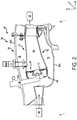
FIG. 2 illustrates a schematic cross-section of a combustor section of a gas turbine engine, in accordance with various embodiments; -
FIG. 3 illustrates a cross-sectional view of a fastener assembly, in accordance with various embodiments; -
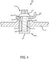
FIG. 4 illustrates a cross-sectional view of a fastener assembly comprising a leak resistant insert having a square shaped end, in accordance with various embodiments; -
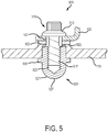
FIG. 5 illustrates a cross-sectional view of a fastener assembly comprising a leak resistant insert having a flange, in accordance with various embodiments; -
FIG. 6 illustrates a cross-sectional view of a fastener assembly comprising a leak resistant insert having a flange engaged with a case wall recess, in accordance with various embodiments; and -
FIG. 7 illustrates a process flow for a method of installing a fastener assembly, in accordance with various embodiments. - Elements and steps in the figures are illustrated for simplicity and clarity and have not necessarily been rendered according to any particular sequence. For example, steps that may be performed concurrently or in different order are illustrated in the figures to help to improve understanding of embodiments of the present disclosure.
- The detailed description of exemplary embodiments herein makes reference to the accompanying drawings, which show exemplary embodiments by way of illustration. While these exemplary embodiments are described in sufficient detail to enable those skilled in the art to practice the disclosures, it should be understood that other embodiments may be realized and that logical changes and adaptations in design and construction may be made in accordance with this disclosure and the teachings herein. Thus, the detailed description herein is presented for purposes of illustration only and not of limitation.
- The scope of the disclosure is defined by the appended claims and their legal equivalents rather than by merely the examples described. For example, the steps recited in any of the method or process descriptions may be executed in any order and are not necessarily limited to the order presented. Furthermore, any reference to singular includes plural embodiments, and any reference to more than one component or step may include a singular embodiment or step. Also, any reference to attached, fixed, coupled, connected or the like may include permanent, removable, temporary, partial, full and/or any other possible attachment option. Additionally, any reference to without contact (or similar phrases) may also include reduced contact or minimal contact. Surface shading lines may be used throughout the figures to denote different parts but not necessarily to denote the same or different materials.
- In various embodiments, and with reference to
FIG. 1 , agas turbine engine 20 is disclosed. As used herein, "aft" refers to the direction associated with a tail (e.g., the back end) of an aircraft, or generally, to the direction of exhaust ofgas turbine engine 20. As used herein, "forward" refers to the direction associated with a nose (e.g., the front end) of the aircraft, or generally, to the direction of flight or motion. An A-R-C axis has been included inFIGs. 1 and2 to illustrate the axial (A), radial (R) and circumferential (C) directions. For clarity, axial axis A spans parallel to engine central longitudinal axis A-A'. As utilized herein, radially inward refers to the negative R direction towards engine central longitudinal axis A-A', and radially outward refers to the R direction away from engine central longitudinal axis A-A'. -
Gas turbine engine 20 may comprise a two-spool turbofan that generally incorporates afan section 22, acompressor section 24, acombustor section 26, and aturbine section 28.Gas turbine engine 20 may also comprise, for example, an augmenter section, and/or any other suitable system, section, or feature. In operation,fan section 22 may drive coolant (e.g., air) along a bypass flow-path B, whilecompressor section 24 may further drive coolant along a core flow-path C for compression and communication intocombustor section 26, before expansion throughturbine section 28.FIG. 1 provides a general understanding of the sections in a gas turbine engine, and is not intended to limit the disclosure. The present disclosure may extend to all types of applications and to all types of turbine engines, including, for example, turbojets, turboshafts, and three spool (plus fan) turbofans wherein an intermediate spool includes an intermediate pressure compressor ("IPC") between a low pressure compressor ("LPC") and a high pressure compressor ("HPC"), and an intermediate pressure turbine ("IPT") between the high pressure turbine ("HPT") and the low pressure turbine ("LPT"). - In various embodiments,
gas turbine engine 20 may comprise alow speed spool 30 and ahigh speed spool 32 mounted for rotation about an engine central longitudinal axis A-A' relative to an enginestatic structure 36 or an engine case via one or more bearing systems 38 (shown as, for example, bearing system 38-1 and bearing system 38-2 inFIG. 1 ). It should be understood that various bearingsystems 38 at various locations may alternatively or additionally be provided, including, for example, bearingsystem 38, bearing system 38-1, and/or bearing system 38-2. - In various embodiments,
low speed spool 30 may comprise aninner shaft 40 that interconnects afan 42, a low pressure (or a first)compressor section 44, and a low pressure (or a second)turbine section 46.Inner shaft 40 may be connected to fan 42 through a gearedarchitecture 48 that can drivefan 42 at a lower speed thanlow speed spool 30.Geared architecture 48 may comprise agear assembly 58 enclosed within agear housing 59.Gear assembly 58 may coupleinner shaft 40 to a rotating fan structure.High speed spool 32 may comprise anouter shaft 50 that interconnects a high pressure compressor ("HPC") 52 (e.g., a second compressor section) and high pressure (or a first)turbine section 54. Acombustor 56 may be located betweenHPC 52 andhigh pressure turbine 54. Amid-turbine frame 57 of enginestatic structure 36 may be located generally betweenhigh pressure turbine 54 andlow pressure turbine 46.Mid-turbine frame 57 may support one ormore bearing systems 38 inturbine section 28.Inner shaft 40 andouter shaft 50 may be concentric and may rotate via bearingsystems 38 about engine central longitudinal axis A-A'. As used herein, a "high pressure" compressor and/or turbine may experience a higher pressure than a corresponding "low pressure" compressor and/or turbine. - In various embodiments, the coolant along core airflow C may be compressed by
low pressure compressor 44 andHPC 52, mixed and burned with fuel incombustor 56, and expanded overhigh pressure turbine 54 andlow pressure turbine 46.Mid-turbine frame 57 may compriseairfoils 65 located in core airflow path C.Low pressure turbine 46 andhigh pressure turbine 54 may rotationally drivelow speed spool 30 andhigh speed spool 32, respectively, in response to the expansion. - In various embodiments,
gas turbine engine 20 may be, for example, a high-bypass ratio geared engine. In various embodiments, the bypass ratio ofgas turbine engine 20 may be greater than about six (6). In various embodiments, the bypass ratio ofgas turbine engine 20 may be greater than ten (10). In various embodiments, gearedarchitecture 48 may be an epicyclic gear train, such as a star gear system (sun gear in meshing engagement with a plurality of star gears supported by a carrier and in meshing engagement with a ring gear) or other gear system.Geared architecture 48 may have a gear reduction ratio of greater than about 2.3 andlow pressure turbine 46 may have a pressure ratio that is greater than about five (5). In various embodiments, the bypass ratio ofgas turbine engine 20 is greater than about ten (10:1). In various embodiments, the diameter offan 42 may be significantly larger than that of thelow pressure compressor 44, and thelow pressure turbine 46 may have a pressure ratio that is greater than about five (5:1).Low pressure turbine 46 pressure ratio may be measured prior to inlet oflow pressure turbine 46 as related to the pressure at the outlet oflow pressure turbine 46 prior to an exhaust nozzle. It should be understood, however, that the above parameters are exemplary of various embodiments of a suitable geared architecture engine and that the present disclosure contemplates other gas turbine engines including direct drive turbofans. Although a gas turbine engine is used for exemplary purposes, the fastener assembly of the present disclosure may be used in various embodiments in any suitable device or apparatus having a fastener coupled to an insert. - With reference now to
FIG. 2 and continued reference toFIG. 1 ,combustor section 26 generally includescombustor 56 with an outercombustor wall assembly 60, an innercombustor wall assembly 62, and adiffuser case module 64 that encasescombustor wall assemblies combustor wall assembly 60 and innercombustor wall assembly 62 are radially spaced apart such that anannular combustion chamber 66 is defined therebetween.Combustion chamber 66 may receive compressed air fromcompressor section 24 and may contain the combustion products that flow axially towardturbine section 28. Outercombustor wall assembly 60 is spaced radially inward from anouter diffuser case 64A ofdiffuser case module 64 to define an outerannular plenum 76. Innercombustor wall assembly 62 is spaced radially outward from aninner diffuser case 64B ofdiffuser case module 64 to define an innerannular plenum 78. -
Combustor section 26, includingdiffuser case module 64, may be a landing point to one or more brackets, panels, shells, assemblies, fuel nozzles, igniters, and/or other structures or components. For example, eachcombustor wall assembly igniter 79 may generally be coupled to and project throughouter diffuser case 64A andcombustor wall assembly 60 to initially ignite a blended fuel-air mixture.Combustor 56 further includes aforward assembly 80 downstream (e.g., aft) ofcompressor section 24 to receive compressed airflow therefrom.Forward assembly 80 introduces core combustion air into the forward section ofcombustion chamber 66 while the remainder enters outerannular plenum 76 and innerannular plenum 78.Forward assembly 80 may generally include abulkhead assembly 84, and one ormore swirler assemblies 82 that are circumferentially spaced from one-another.Bulkhead assembly 84 includes a bulkhead support shell secured tocombustor wall assemblies respective swirler assembly 82 opening. Eachswirler assembly 82 is circumferentially aligned with one of a plurality offuel nozzles 86 and a respective hood ports. The fuel nozzles 86,swirler assemblies 82, and adjacent structures generate the blended fuel-air mixture that supports stable combustion incombustion chamber 66. - Each of the brackets, panels, shells, assemblies, fuel nozzles, igniters, and/or other structures or components may be coupled to
combustor wall assembly diffuser case module 64, includingdiffuser case FIG. 3 , afastener assembly 300 may be used to couple the various structures or components tocombustor wall assembly diffuser case module 64, includingdiffuser case - In various embodiments,
fastener assembly 300 may be configured to couple a mounting plate 105 (e.g., a bracket, panel, shell, assembly, fuel nozzle, igniter, etc., as discussed herein) to a case wall 101(e.g., a surface ofcombustor wall assembly diffuser case Fastener assembly 300 may be configured to fluidly seal the coupling between mountingplate 105 andcase wall 101 to at least partially reduce fluid leakage. For example, fluid (e.g., air, gas, etc.) may pass betweenhead 313 offastener 310 and mountingplate 105, into mountingplate hole 107 andcase wall hole 103, and between the threading of threadedbody 317 and inner threaded surface 323 (e.g., through a leak path). Insert end 327 of leakresistant insert 320 may enclose the threading of threadedbody 317 and inner threadedsurface 323 to fluidly seal the leak path throughfastener assembly 300. In various embodiments, at least partially reducing the leakage of fluid (e.g., hot gases) throughfastener assembly 300 may further improve gas turbine engine efficiency and fuel economy. - In various embodiments,
fastener assembly 300 may comprise afastener 310 and a leakresistant insert 320.Fastener 310 may be configured to insert through mountingplate hole 107 andcase wall hole 103, and into leakresistant insert 320.Fastener 310 may comprise any suitable type of fastener, bolt, or the like, and may be sized and shaped to fit through mountingplate hole 107 andcase wall hole 103, and into leakresistant insert 320.Fastener 310 may comprise ahead 313 coupled to a threadedbody 317.Head 313 may comprise any type of fastener head, such as, for example, a round head, a hex cap, a pan head, a flat head, a truss head, a fillister head, and/or any other suitable type of fastener head. Threadedbody 317 may comprise a threaded outer surface (e.g., a spiral-grooved configuration, and/or any other suitable threaded configuration) configured to engage inner threadedsurface 323 of leakresistant insert 320 tocouple fastener 310 to leakresistant insert 320. In that respect,fastener 310 may be configured to insert through mountingplate hole 107 andcase wall hole 103, and into leakresistant insert 320 to couplecase wall 101 to mountingplate 105. - In various embodiments, leak resistant insert 320 (e.g., a leak resistant fastener insert) may be configured to at least partially fluidly seal the coupling of mounting
plate 105 tocase wall 101. Leakresistant insert 320 may comprise any suitable shape and size. Leakresistant insert 320 may be monolithic (e.g., a single solid structure). Leakresistant insert 320 may be sized and shaped to be inserted intocase wall hole 103. In response to leakresistant insert 320 being inserted intocase wall hole 103, anouter surface 321 of leakresistant insert 320 may contact the surface ofcase wall hole 103 to fluidly seal the coupling. Leakresistant insert 320 may comprise any material, such as, for example, a nickel alloy, a nickel-chromium alloy (such as that sold under the mark INCONEL, e.g., INCONEL 600, 617, 618, 625, 718, X-70, etc.), a titanium alloy, a cobalt alloy, a corrosion resistant steel, and/or any other suitable material having properties resistant to oxidation and corrosion in a variety of environments and temperature ranges. Leakresistant insert 320 may be formed using any suitable process, such as, for example, by machining, investment casting, additive manufacturing (e.g., fused deposition modeling, polyjet 3D printing, direct metal laser sintering, etc.), or the like. Additive manufacturing techniques may enable the formation of complex contours on leakresistant insert 320, such as, for example, the grooves on inner threadedsurface 323. - Leak
resistant insert 320 may comprise aninsert opening 325 opposite aninsert end 327. Leakresistant insert 320 may also compriseouter surface 321 opposite an inner threadedsurface 323. Inner threadedsurface 323 may defineinsert opening 325 through leak resistant insert 325 (e.g., insert opening 325 and inner threadedsurface 323 may define a void through leak resistant insert 320). In that respect, insert opening 325 and inner threadedsurface 323 may be sized and shaped to receivefastener 310. Inner threadedsurface 323 may comprise a threaded surface (e.g., a spiral-grooved configuration, and/or any other suitable threaded configuration) configured to engage threadedbody 317 offastener 310 in response tofastener 310 being inserted into leakresistant insert 320.Outer surface 321 may be configured to contact the surface ofcase wall hole 103 in response to leakresistant insert 320 being installed withincase wall hole 103. -
Outer surface 321 may define insert end 327 to enclose inner threadedsurface 323opposite insert opening 325. Insert end 327 may be configured to fluidly sealfastener assembly 300 in response tofastener 310 engaging leakresistant insert 320. Insert end 327 may comprise any suitable shape capable of fluidly sealing the coupling of threadedbody 317 and inner threadedsurface 323. For example, insertend 327 may comprise a conical shape, an elliptical shape, a parabolic shape, a stepped shape, a concave shape, a hemispherical shape, or the like. In various embodiments, and with reference toFIG. 4 , a leakresistant insert 420 may also comprise aninsert end 427 having a square shape. Leakresistant insert 420 may be similar to leakresistant insert 320, with brief reference toFIG. 3 . - In various embodiments, and with reference to
FIG. 5 , a leakresistant insert 520 may further comprise aflange 530. Leakresistant insert 520 may be similar to leakresistant insert 320, with brief reference toFIG. 3 .Flange 530 may define a radial protrusion fromouter surface 321.Flange 530 may be locatedproximate insert opening 325, at a midpoint between insert opening 325 and insertend 327, and/or at any other suitable location onouter surface 321.Flange 530 may comprise any suitable size and shape, and may be configured to contact a surface ofcase wall 101 in response to leakresistant insert 520 being installed intocase wall hole 103. With reference toFIG. 6 , and in accordance with various embodiments,flange 530 may be configured to engage acase wall recess 602 incase wall 601. In that regard, in response to leakresistant insert 520 being installed intocase wall hole 103,flange 530 may be configured to fit withincase wall recess 602 to further the coupling (and fluid seal) of secure leakresistant insert 520 tocase wall 101. - In various embodiments, and with combined reference to
FIG. 7 andFIG. 3 , amethod 701 for installing afastener assembly 300 having a leakresistant insert 320 is disclosed.Method 701 may be used to couple mountingplate 105 tocase wall 101 viafastener assembly 300.Method 701 may comprise inserting leakresistant insert 320 into case wall hole 103 (step 702). Leakresistant insert 320 may be inserted intocase wall hole 103 using any suitable technique and process. For example, a press fit installation process may be used wherein a lubricant is provided on to at least one ofouter surface 321 and/orcase wall hole 103, and leakresistant insert 320 is pressed into case wall hole 103 (e.g., using an arbor press or the like). As a further example, a shrink fit installation process may be used wherein leakresistant insert 320 is first cooled to a low temperature using dry ice or liquid nitrogen to allow leakresistant insert 320 to contract in size before installation intocase wall hole 103, and expand in size post-installation. - In various embodiments,
method 701 may comprise aligning mountingplate 105 with case wall 101 (step 704). For example, mountingplate 105 may be placed ontocase wall 101, and mountingplate hole 107 may be aligned withcase wall hole 103.Method 701 may comprise insertingfastener 310 through mountingplate hole 107 and case wall hole 103 (step 704).Method 701 may comprise engagingfastener 310 with leak resistant insert 320 (step 706).Fastener 310 may be inserted into leakresistant insert 320 and rotated or tightened to engage the threading on threadedbody 317 with the threading on inner threadedsurface 323. In that regard, in response to engagingfastener 310 with leakresistant insert 320,fastener assembly 300 may couple mountingplate 105 tocase wall 101. - Benefits, other advantages, and solutions to problems have been described herein with regard to specific embodiments. Furthermore, the connecting lines shown in the various figures contained herein are intended to represent exemplary functional relationships and/or physical couplings between the various elements. It should be noted that many alternative or additional functional relationships or physical connections may be present in a practical system. However, the benefits, advantages, solutions to problems, and any elements that may cause any benefit, advantage, or solution to occur or become more pronounced are not to be construed as critical, required, or essential features or elements of the disclosures. The scope of the disclosures is accordingly to be limited by nothing other than the appended claims and their legal equivalents, in which reference to an element in the singular is not intended to mean "one and only one" unless explicitly so stated, but rather "one or more." Moreover, where a phrase similar to "at least one of A, B, or C" is used in the claims, it is intended that the phrase be interpreted to mean that A alone may be present in an embodiment, B alone may be present in an embodiment, C alone may be present in an embodiment, or that any combination of the elements A, B and C may be present in a single embodiment; for example, A and B, A and C, B and C, or A and B and C.
- Systems, methods and apparatus are provided herein. In the detailed description herein, references to "various embodiments", "one embodiment", "an embodiment", "an example embodiment", etc., indicate that the embodiment described may include a particular feature, structure, or characteristic, but every embodiment may not necessarily include the particular feature, structure, or characteristic. Moreover, such phrases are not necessarily referring to the same embodiment. Further, when a particular feature, structure, or characteristic is described in connection with an embodiment, it is submitted that it is within the knowledge of one skilled in the art to affect such feature, structure, or characteristic in connection with other embodiments whether or not explicitly described. After reading the description, it will be apparent to one skilled in the relevant art(s) how to implement the disclosure in alternative embodiments.
- Furthermore, no element, component, or method step in the present disclosure is intended to be dedicated to the public regardless of whether the element, component, or method step is explicitly recited in the claims. No claim element is intended to be interpreted as a means-plus-function element unless the element is expressly recited using the phrase "means for." As used herein, the terms "comprises", "comprising", or any other variation thereof, are intended to cover a non-exclusive inclusion, such that a process, method, article, or apparatus that comprises a list of elements does not include only those elements but may include other elements not expressly listed or inherent to such process, method, article, or apparatus.
Claims (11)
- A leak resistant fastener insert, comprising:an outer surface; andan inner threaded surface opposite the outer surface, the inner threaded surface defining an insert opening configured to receive a fastener, and the outer surface defining an insert end enclosing the inner threaded surface opposite the insert opening.
- The leak resistant fastener insert of claim 1, further comprising a flange defining a radial protrusion from the outer surface.
- The leak resistant fastener insert of claim 1 or 2, wherein the insert end comprises at least one of a conical shape, an elliptical shape, a parabolic shape, a stepped shape, a concave shape, or a hemispherical shape.
- The leak resistant fastener insert of claim 1, 2 or 3, wherein the insert end comprises a square shape.
- The leak resistant fastener insert of any preceding claim, wherein the leak resistant fastener insert comprises a nickel-chromium alloy material, a titanium alloy material, a cobalt alloy material, or a corrosion resistant steel material.
- The leak resistant fastener insert of any preceding claim, wherein the leak resistant fastener insert is monolithic.
- A fastener assembly, comprising:a leak resistant insert as claimed in any preceding claim; anda fastener inserted within the insert opening and coupled to the inner threaded surface of the leak resistant insert.
- The fastener assembly of claim 7, wherein the fastener comprises a threaded body configured to engage the inner threaded surface of the leak resistant insert in response to the fastener being coupled to the leak resistant insert.
- A gas turbine engine, comprising:a compressor section;a combustor section; anda turbine section,wherein at least one of the compressor section, the combustor section, or the turbine section has a fastener assembly for mounting structures, the fastener assembly comprising:a leak resistant insert as claimed in any of claims 1 to 6; anda fastener inserted within the insert opening and coupled to the inner threaded surface of the leak resistant insert.
- The gas turbine engine of claim 9, wherein the fastener assembly is installed within at least one of the compressor section, the combustor section, or the turbine section using at least one of a press fit installation process or a shrink fit installation process.
- The gas turbine engine of claim 10, wherein the fastener comprises a threaded body configured to engage the inner threaded surface of the leak resistant insert in response to the fastener being coupled to the leak resistant insert.
Applications Claiming Priority (1)
| Application Number | Priority Date | Filing Date | Title |
|---|---|---|---|
| US15/909,037 US11009060B2 (en) | 2018-03-01 | 2018-03-01 | Fastener assembly having a leak resistant threaded insert |
Publications (2)
| Publication Number | Publication Date |
|---|---|
| EP3534071A1 true EP3534071A1 (en) | 2019-09-04 |
| EP3534071B1 EP3534071B1 (en) | 2023-08-23 |
Family
ID=65818155
Family Applications (1)
| Application Number | Title | Priority Date | Filing Date |
|---|---|---|---|
| EP19160138.4A Active EP3534071B1 (en) | 2018-03-01 | 2019-02-28 | Gas turbine engine comprising a fastener assembly having a leak resistant threaded insert |
Country Status (2)
| Country | Link |
|---|---|
| US (1) | US11009060B2 (en) |
| EP (1) | EP3534071B1 (en) |
Families Citing this family (3)
| Publication number | Priority date | Publication date | Assignee | Title |
|---|---|---|---|---|
| US9879565B2 (en) * | 2015-01-20 | 2018-01-30 | United Technologies Corporation | Enclosed jacking insert |
| DE102015009044A1 (en) * | 2015-07-13 | 2017-01-19 | Sfs Intec Holding Ag | Process for the preparation of a compound |
| EP4624771A1 (en) * | 2024-03-27 | 2025-10-01 | Aaf Ltd. | Sealing assembly for mounting parts of a sealing surface |
Citations (7)
| Publication number | Priority date | Publication date | Assignee | Title |
|---|---|---|---|---|
| GB647302A (en) * | 1948-05-14 | 1950-12-13 | Edgar Phillips Peregrine | Improvements in or relating to linings for combustion chambers and the like |
| US6415610B1 (en) * | 2000-08-18 | 2002-07-09 | Siemens Westinghouse Power Corporation | Apparatus and method for replacement of combustor basket swirlers |
| US20040118127A1 (en) * | 2002-12-20 | 2004-06-24 | Mitchell Krista Anne | Mounting assembly for the aft end of a ceramic matrix composite liner in a gas turbine engine combustor |
| EP1464853A1 (en) * | 2003-04-03 | 2004-10-06 | Siemens Aktiengesellschaft | Self-locking mounting device |
| US20060174631A1 (en) * | 2005-02-08 | 2006-08-10 | Siemens Westinghouse Power Corporation | Turbine engine combustor with bolted swirlers |
| EP1793097A1 (en) * | 2005-11-30 | 2007-06-06 | General Electric Company | Apparatus for assembling a gas turbine engine |
| US20110081234A1 (en) * | 2009-10-01 | 2011-04-07 | Pratt & Whitney Canada Corp. | Gas turbine engine thermal expansion joint |
Family Cites Families (8)
| Publication number | Priority date | Publication date | Assignee | Title |
|---|---|---|---|---|
| US2188422A (en) * | 1937-06-09 | 1940-01-30 | Goodrich Co B F | Fluid-tight attachment and tubular rivet therefor |
| DE1625306B1 (en) * | 1967-10-24 | 1971-02-25 | Daimler Benz Ag | SOCKET NUT FOR A SCREW CONNECTION |
| US4905931A (en) | 1988-02-18 | 1990-03-06 | The Boeing Company | Arc suppression around fasteners |
| DE19930728B4 (en) * | 1999-07-05 | 2005-12-01 | Itw-Ateco Gmbh | Anchor for fixing an object to a carrier made of flat material |
| US7597517B2 (en) | 2000-06-23 | 2009-10-06 | Hi-Shear Corporation | Swage collar with internal sealing insert |
| US6726422B2 (en) * | 2001-11-02 | 2004-04-27 | Newfrey Llc | Helically coiled titanium wire fastener inserts |
| US8057144B2 (en) * | 2004-08-27 | 2011-11-15 | Fatigue Technology, Inc. | Sealed, blind fastener assembly |
| US10260546B2 (en) * | 2016-07-07 | 2019-04-16 | Ford Global Technologies, Llc | Insert nut and fastening system with integral seal and bumper |
-
2018
- 2018-03-01 US US15/909,037 patent/US11009060B2/en active Active
-
2019
- 2019-02-28 EP EP19160138.4A patent/EP3534071B1/en active Active
Patent Citations (7)
| Publication number | Priority date | Publication date | Assignee | Title |
|---|---|---|---|---|
| GB647302A (en) * | 1948-05-14 | 1950-12-13 | Edgar Phillips Peregrine | Improvements in or relating to linings for combustion chambers and the like |
| US6415610B1 (en) * | 2000-08-18 | 2002-07-09 | Siemens Westinghouse Power Corporation | Apparatus and method for replacement of combustor basket swirlers |
| US20040118127A1 (en) * | 2002-12-20 | 2004-06-24 | Mitchell Krista Anne | Mounting assembly for the aft end of a ceramic matrix composite liner in a gas turbine engine combustor |
| EP1464853A1 (en) * | 2003-04-03 | 2004-10-06 | Siemens Aktiengesellschaft | Self-locking mounting device |
| US20060174631A1 (en) * | 2005-02-08 | 2006-08-10 | Siemens Westinghouse Power Corporation | Turbine engine combustor with bolted swirlers |
| EP1793097A1 (en) * | 2005-11-30 | 2007-06-06 | General Electric Company | Apparatus for assembling a gas turbine engine |
| US20110081234A1 (en) * | 2009-10-01 | 2011-04-07 | Pratt & Whitney Canada Corp. | Gas turbine engine thermal expansion joint |
Also Published As
| Publication number | Publication date |
|---|---|
| EP3534071B1 (en) | 2023-08-23 |
| US20190271352A1 (en) | 2019-09-05 |
| US11009060B2 (en) | 2021-05-18 |
Similar Documents
| Publication | Publication Date | Title |
|---|---|---|
| EP3404329B1 (en) | Combustor panel endrail interface | |
| US10837635B2 (en) | Fuel swirler with anti-rotation features | |
| EP3453965B1 (en) | Cooling configuration for combustor attachment feature | |
| US10436449B2 (en) | Light weight swirler for gas turbine engine combustor and a method for lightening a swirler for a gas turbine engine | |
| EP3587928A1 (en) | Combustor shell attachment | |
| US20160245518A1 (en) | Combustor panel with multiple attachments | |
| EP3404330A1 (en) | Redundant endrail for combustor panel | |
| EP3534071B1 (en) | Gas turbine engine comprising a fastener assembly having a leak resistant threaded insert | |
| US20190285276A1 (en) | Castellated combustor panels | |
| US11136995B2 (en) | Pre-diffuser for a gas turbine engine | |
| EP3260739B1 (en) | Low-cost epicyclic gear carrier and method of making the same | |
| EP3719260A1 (en) | Pre-diffuser for a gas turbine engine | |
| US20200318833A1 (en) | Pre-diffuser for a gas turbine engine | |
| US11175041B2 (en) | Systems and methods for combustor panel | |
| EP2910752B1 (en) | Fuel manifold fitting with integral support for a gas turbine engine and method of mounting a fuel supply manifold assembly | |
| EP3677837B1 (en) | Combustor cooling panel with flow guide | |
| EP3677836A1 (en) | Combustor panel stud cooling by effusion through heat transfer augmentors |
Legal Events
| Date | Code | Title | Description |
|---|---|---|---|
| PUAI | Public reference made under article 153(3) epc to a published international application that has entered the european phase |
Free format text: ORIGINAL CODE: 0009012 |
|
| STAA | Information on the status of an ep patent application or granted ep patent |
Free format text: STATUS: THE APPLICATION HAS BEEN PUBLISHED |
|
| AK | Designated contracting states |
Kind code of ref document: A1 Designated state(s): AL AT BE BG CH CY CZ DE DK EE ES FI FR GB GR HR HU IE IS IT LI LT LU LV MC MK MT NL NO PL PT RO RS SE SI SK SM TR |
|
| AX | Request for extension of the european patent |
Extension state: BA ME |
|
| STAA | Information on the status of an ep patent application or granted ep patent |
Free format text: STATUS: REQUEST FOR EXAMINATION WAS MADE |
|
| 17P | Request for examination filed |
Effective date: 20200304 |
|
| RBV | Designated contracting states (corrected) |
Designated state(s): AL AT BE BG CH CY CZ DE DK EE ES FI FR GB GR HR HU IE IS IT LI LT LU LV MC MK MT NL NO PL PT RO RS SE SI SK SM TR |
|
| STAA | Information on the status of an ep patent application or granted ep patent |
Free format text: STATUS: EXAMINATION IS IN PROGRESS |
|
| 17Q | First examination report despatched |
Effective date: 20201030 |
|
| RAP1 | Party data changed (applicant data changed or rights of an application transferred) |
Owner name: RAYTHEON TECHNOLOGIES CORPORATION |
|
| GRAP | Despatch of communication of intention to grant a patent |
Free format text: ORIGINAL CODE: EPIDOSNIGR1 |
|
| STAA | Information on the status of an ep patent application or granted ep patent |
Free format text: STATUS: GRANT OF PATENT IS INTENDED |
|
| INTG | Intention to grant announced |
Effective date: 20230323 |
|
| GRAS | Grant fee paid |
Free format text: ORIGINAL CODE: EPIDOSNIGR3 |
|
| GRAA | (expected) grant |
Free format text: ORIGINAL CODE: 0009210 |
|
| STAA | Information on the status of an ep patent application or granted ep patent |
Free format text: STATUS: THE PATENT HAS BEEN GRANTED |
|
| AK | Designated contracting states |
Kind code of ref document: B1 Designated state(s): AL AT BE BG CH CY CZ DE DK EE ES FI FR GB GR HR HU IE IS IT LI LT LU LV MC MK MT NL NO PL PT RO RS SE SI SK SM TR |
|
| REG | Reference to a national code |
Ref country code: GB Ref legal event code: FG4D |
|
| REG | Reference to a national code |
Ref country code: CH Ref legal event code: EP |
|
| REG | Reference to a national code |
Ref country code: IE Ref legal event code: FG4D |
|
| REG | Reference to a national code |
Ref country code: DE Ref legal event code: R096 Ref document number: 602019035408 Country of ref document: DE |
|
| RAP4 | Party data changed (patent owner data changed or rights of a patent transferred) |
Owner name: RTX CORPORATION |
|
| REG | Reference to a national code |
Ref country code: LT Ref legal event code: MG9D |
|
| REG | Reference to a national code |
Ref country code: NL Ref legal event code: MP Effective date: 20230823 |
|
| REG | Reference to a national code |
Ref country code: AT Ref legal event code: MK05 Ref document number: 1602994 Country of ref document: AT Kind code of ref document: T Effective date: 20230823 |
|
| PG25 | Lapsed in a contracting state [announced via postgrant information from national office to epo] |
Ref country code: GR Free format text: LAPSE BECAUSE OF FAILURE TO SUBMIT A TRANSLATION OF THE DESCRIPTION OR TO PAY THE FEE WITHIN THE PRESCRIBED TIME-LIMIT Effective date: 20231124 |
|
| PG25 | Lapsed in a contracting state [announced via postgrant information from national office to epo] |
Ref country code: IS Free format text: LAPSE BECAUSE OF FAILURE TO SUBMIT A TRANSLATION OF THE DESCRIPTION OR TO PAY THE FEE WITHIN THE PRESCRIBED TIME-LIMIT Effective date: 20231223 |
|
| PG25 | Lapsed in a contracting state [announced via postgrant information from national office to epo] |
Ref country code: SE Free format text: LAPSE BECAUSE OF FAILURE TO SUBMIT A TRANSLATION OF THE DESCRIPTION OR TO PAY THE FEE WITHIN THE PRESCRIBED TIME-LIMIT Effective date: 20230823 Ref country code: RS Free format text: LAPSE BECAUSE OF FAILURE TO SUBMIT A TRANSLATION OF THE DESCRIPTION OR TO PAY THE FEE WITHIN THE PRESCRIBED TIME-LIMIT Effective date: 20230823 Ref country code: PT Free format text: LAPSE BECAUSE OF FAILURE TO SUBMIT A TRANSLATION OF THE DESCRIPTION OR TO PAY THE FEE WITHIN THE PRESCRIBED TIME-LIMIT Effective date: 20231226 Ref country code: NO Free format text: LAPSE BECAUSE OF FAILURE TO SUBMIT A TRANSLATION OF THE DESCRIPTION OR TO PAY THE FEE WITHIN THE PRESCRIBED TIME-LIMIT Effective date: 20231123 Ref country code: NL Free format text: LAPSE BECAUSE OF FAILURE TO SUBMIT A TRANSLATION OF THE DESCRIPTION OR TO PAY THE FEE WITHIN THE PRESCRIBED TIME-LIMIT Effective date: 20230823 Ref country code: LV Free format text: LAPSE BECAUSE OF FAILURE TO SUBMIT A TRANSLATION OF THE DESCRIPTION OR TO PAY THE FEE WITHIN THE PRESCRIBED TIME-LIMIT Effective date: 20230823 Ref country code: LT Free format text: LAPSE BECAUSE OF FAILURE TO SUBMIT A TRANSLATION OF THE DESCRIPTION OR TO PAY THE FEE WITHIN THE PRESCRIBED TIME-LIMIT Effective date: 20230823 Ref country code: IS Free format text: LAPSE BECAUSE OF FAILURE TO SUBMIT A TRANSLATION OF THE DESCRIPTION OR TO PAY THE FEE WITHIN THE PRESCRIBED TIME-LIMIT Effective date: 20231223 Ref country code: HR Free format text: LAPSE BECAUSE OF FAILURE TO SUBMIT A TRANSLATION OF THE DESCRIPTION OR TO PAY THE FEE WITHIN THE PRESCRIBED TIME-LIMIT Effective date: 20230823 Ref country code: GR Free format text: LAPSE BECAUSE OF FAILURE TO SUBMIT A TRANSLATION OF THE DESCRIPTION OR TO PAY THE FEE WITHIN THE PRESCRIBED TIME-LIMIT Effective date: 20231124 Ref country code: FI Free format text: LAPSE BECAUSE OF FAILURE TO SUBMIT A TRANSLATION OF THE DESCRIPTION OR TO PAY THE FEE WITHIN THE PRESCRIBED TIME-LIMIT Effective date: 20230823 Ref country code: AT Free format text: LAPSE BECAUSE OF FAILURE TO SUBMIT A TRANSLATION OF THE DESCRIPTION OR TO PAY THE FEE WITHIN THE PRESCRIBED TIME-LIMIT Effective date: 20230823 |
|
| PG25 | Lapsed in a contracting state [announced via postgrant information from national office to epo] |
Ref country code: PL Free format text: LAPSE BECAUSE OF FAILURE TO SUBMIT A TRANSLATION OF THE DESCRIPTION OR TO PAY THE FEE WITHIN THE PRESCRIBED TIME-LIMIT Effective date: 20230823 |
|
| PG25 | Lapsed in a contracting state [announced via postgrant information from national office to epo] |
Ref country code: ES Free format text: LAPSE BECAUSE OF FAILURE TO SUBMIT A TRANSLATION OF THE DESCRIPTION OR TO PAY THE FEE WITHIN THE PRESCRIBED TIME-LIMIT Effective date: 20230823 |
|
| PG25 | Lapsed in a contracting state [announced via postgrant information from national office to epo] |
Ref country code: SM Free format text: LAPSE BECAUSE OF FAILURE TO SUBMIT A TRANSLATION OF THE DESCRIPTION OR TO PAY THE FEE WITHIN THE PRESCRIBED TIME-LIMIT Effective date: 20230823 Ref country code: RO Free format text: LAPSE BECAUSE OF FAILURE TO SUBMIT A TRANSLATION OF THE DESCRIPTION OR TO PAY THE FEE WITHIN THE PRESCRIBED TIME-LIMIT Effective date: 20230823 Ref country code: ES Free format text: LAPSE BECAUSE OF FAILURE TO SUBMIT A TRANSLATION OF THE DESCRIPTION OR TO PAY THE FEE WITHIN THE PRESCRIBED TIME-LIMIT Effective date: 20230823 Ref country code: EE Free format text: LAPSE BECAUSE OF FAILURE TO SUBMIT A TRANSLATION OF THE DESCRIPTION OR TO PAY THE FEE WITHIN THE PRESCRIBED TIME-LIMIT Effective date: 20230823 Ref country code: DK Free format text: LAPSE BECAUSE OF FAILURE TO SUBMIT A TRANSLATION OF THE DESCRIPTION OR TO PAY THE FEE WITHIN THE PRESCRIBED TIME-LIMIT Effective date: 20230823 Ref country code: CZ Free format text: LAPSE BECAUSE OF FAILURE TO SUBMIT A TRANSLATION OF THE DESCRIPTION OR TO PAY THE FEE WITHIN THE PRESCRIBED TIME-LIMIT Effective date: 20230823 Ref country code: SK Free format text: LAPSE BECAUSE OF FAILURE TO SUBMIT A TRANSLATION OF THE DESCRIPTION OR TO PAY THE FEE WITHIN THE PRESCRIBED TIME-LIMIT Effective date: 20230823 |
|
| REG | Reference to a national code |
Ref country code: DE Ref legal event code: R097 Ref document number: 602019035408 Country of ref document: DE |
|
| PG25 | Lapsed in a contracting state [announced via postgrant information from national office to epo] |
Ref country code: IT Free format text: LAPSE BECAUSE OF FAILURE TO SUBMIT A TRANSLATION OF THE DESCRIPTION OR TO PAY THE FEE WITHIN THE PRESCRIBED TIME-LIMIT Effective date: 20230823 |
|
| PLBE | No opposition filed within time limit |
Free format text: ORIGINAL CODE: 0009261 |
|
| STAA | Information on the status of an ep patent application or granted ep patent |
Free format text: STATUS: NO OPPOSITION FILED WITHIN TIME LIMIT |
|
| 26N | No opposition filed |
Effective date: 20240524 |
|
| PG25 | Lapsed in a contracting state [announced via postgrant information from national office to epo] |
Ref country code: SI Free format text: LAPSE BECAUSE OF FAILURE TO SUBMIT A TRANSLATION OF THE DESCRIPTION OR TO PAY THE FEE WITHIN THE PRESCRIBED TIME-LIMIT Effective date: 20230823 |
|
| PG25 | Lapsed in a contracting state [announced via postgrant information from national office to epo] |
Ref country code: MC Free format text: LAPSE BECAUSE OF FAILURE TO SUBMIT A TRANSLATION OF THE DESCRIPTION OR TO PAY THE FEE WITHIN THE PRESCRIBED TIME-LIMIT Effective date: 20230823 |
|
| REG | Reference to a national code |
Ref country code: CH Ref legal event code: PL |
|
| PG25 | Lapsed in a contracting state [announced via postgrant information from national office to epo] |
Ref country code: LU Free format text: LAPSE BECAUSE OF NON-PAYMENT OF DUE FEES Effective date: 20240228 |
|
| PG25 | Lapsed in a contracting state [announced via postgrant information from national office to epo] |
Ref country code: CH Free format text: LAPSE BECAUSE OF NON-PAYMENT OF DUE FEES Effective date: 20240229 |
|
| PG25 | Lapsed in a contracting state [announced via postgrant information from national office to epo] |
Ref country code: LU Free format text: LAPSE BECAUSE OF NON-PAYMENT OF DUE FEES Effective date: 20240228 Ref country code: CH Free format text: LAPSE BECAUSE OF NON-PAYMENT OF DUE FEES Effective date: 20240229 |
|
| PG25 | Lapsed in a contracting state [announced via postgrant information from national office to epo] |
Ref country code: BG Free format text: LAPSE BECAUSE OF FAILURE TO SUBMIT A TRANSLATION OF THE DESCRIPTION OR TO PAY THE FEE WITHIN THE PRESCRIBED TIME-LIMIT Effective date: 20230823 |
|
| PG25 | Lapsed in a contracting state [announced via postgrant information from national office to epo] |
Ref country code: BG Free format text: LAPSE BECAUSE OF FAILURE TO SUBMIT A TRANSLATION OF THE DESCRIPTION OR TO PAY THE FEE WITHIN THE PRESCRIBED TIME-LIMIT Effective date: 20230823 |
|
| REG | Reference to a national code |
Ref country code: BE Ref legal event code: MM Effective date: 20240229 |
|
| PG25 | Lapsed in a contracting state [announced via postgrant information from national office to epo] |
Ref country code: BE Free format text: LAPSE BECAUSE OF NON-PAYMENT OF DUE FEES Effective date: 20240229 |
|
| PG25 | Lapsed in a contracting state [announced via postgrant information from national office to epo] |
Ref country code: IE Free format text: LAPSE BECAUSE OF NON-PAYMENT OF DUE FEES Effective date: 20240228 |
|
| PG25 | Lapsed in a contracting state [announced via postgrant information from national office to epo] |
Ref country code: IE Free format text: LAPSE BECAUSE OF NON-PAYMENT OF DUE FEES Effective date: 20240228 Ref country code: BE Free format text: LAPSE BECAUSE OF NON-PAYMENT OF DUE FEES Effective date: 20240229 |
|
| PG25 | Lapsed in a contracting state [announced via postgrant information from national office to epo] |
Ref country code: CY Free format text: LAPSE BECAUSE OF FAILURE TO SUBMIT A TRANSLATION OF THE DESCRIPTION OR TO PAY THE FEE WITHIN THE PRESCRIBED TIME-LIMIT; INVALID AB INITIO Effective date: 20190228 |
|
| PG25 | Lapsed in a contracting state [announced via postgrant information from national office to epo] |
Ref country code: HU Free format text: LAPSE BECAUSE OF FAILURE TO SUBMIT A TRANSLATION OF THE DESCRIPTION OR TO PAY THE FEE WITHIN THE PRESCRIBED TIME-LIMIT; INVALID AB INITIO Effective date: 20190228 |
|
| REG | Reference to a national code |
Ref country code: DE Ref legal event code: R081 Ref document number: 602019035408 Country of ref document: DE Owner name: RTX CORPORATION (N.D.GES.D. STAATES DELAWARE),, US Free format text: FORMER OWNER: RAYTHEON TECHNOLOGIES CORPORATION, FARMINGTON, CT, US |
|
| PG25 | Lapsed in a contracting state [announced via postgrant information from national office to epo] |
Ref country code: TR Free format text: LAPSE BECAUSE OF FAILURE TO SUBMIT A TRANSLATION OF THE DESCRIPTION OR TO PAY THE FEE WITHIN THE PRESCRIBED TIME-LIMIT Effective date: 20230823 |
|
| P01 | Opt-out of the competence of the unified patent court (upc) registered |
Free format text: CASE NUMBER: UPC_APP_0019220_3534071/2025 Effective date: 20251223 |
|
| PGFP | Annual fee paid to national office [announced via postgrant information from national office to epo] |
Ref country code: GB Payment date: 20260122 Year of fee payment: 8 |
|
| PGFP | Annual fee paid to national office [announced via postgrant information from national office to epo] |
Ref country code: DE Payment date: 20260121 Year of fee payment: 8 |
|
| PGFP | Annual fee paid to national office [announced via postgrant information from national office to epo] |
Ref country code: FR Payment date: 20260121 Year of fee payment: 8 |