EP3677836A1 - Combustor panel stud cooling by effusion through heat transfer augmentors - Google Patents
Combustor panel stud cooling by effusion through heat transfer augmentors Download PDFInfo
- Publication number
- EP3677836A1 EP3677836A1 EP20150376.0A EP20150376A EP3677836A1 EP 3677836 A1 EP3677836 A1 EP 3677836A1 EP 20150376 A EP20150376 A EP 20150376A EP 3677836 A1 EP3677836 A1 EP 3677836A1
- Authority
- EP
- European Patent Office
- Prior art keywords
- heat transfer
- gas turbine
- turbine engine
- engine component
- panel
- Prior art date
- Legal status (The legal status is an assumption and is not a legal conclusion. Google has not performed a legal analysis and makes no representation as to the accuracy of the status listed.)
- Pending
Links
Images


Classifications
-
- F—MECHANICAL ENGINEERING; LIGHTING; HEATING; WEAPONS; BLASTING
- F23—COMBUSTION APPARATUS; COMBUSTION PROCESSES
- F23R—GENERATING COMBUSTION PRODUCTS OF HIGH PRESSURE OR HIGH VELOCITY, e.g. GAS-TURBINE COMBUSTION CHAMBERS
- F23R3/00—Continuous combustion chambers using liquid or gaseous fuel
- F23R3/005—Combined with pressure or heat exchangers
-
- F—MECHANICAL ENGINEERING; LIGHTING; HEATING; WEAPONS; BLASTING
- F23—COMBUSTION APPARATUS; COMBUSTION PROCESSES
- F23R—GENERATING COMBUSTION PRODUCTS OF HIGH PRESSURE OR HIGH VELOCITY, e.g. GAS-TURBINE COMBUSTION CHAMBERS
- F23R3/00—Continuous combustion chambers using liquid or gaseous fuel
- F23R3/002—Wall structures
-
- F—MECHANICAL ENGINEERING; LIGHTING; HEATING; WEAPONS; BLASTING
- F23—COMBUSTION APPARATUS; COMBUSTION PROCESSES
- F23R—GENERATING COMBUSTION PRODUCTS OF HIGH PRESSURE OR HIGH VELOCITY, e.g. GAS-TURBINE COMBUSTION CHAMBERS
- F23R3/00—Continuous combustion chambers using liquid or gaseous fuel
- F23R3/02—Continuous combustion chambers using liquid or gaseous fuel characterised by the air-flow or gas-flow configuration
- F23R3/04—Air inlet arrangements
- F23R3/06—Arrangement of apertures along the flame tube
-
- F—MECHANICAL ENGINEERING; LIGHTING; HEATING; WEAPONS; BLASTING
- F02—COMBUSTION ENGINES; HOT-GAS OR COMBUSTION-PRODUCT ENGINE PLANTS
- F02C—GAS-TURBINE PLANTS; AIR INTAKES FOR JET-PROPULSION PLANTS; CONTROLLING FUEL SUPPLY IN AIR-BREATHING JET-PROPULSION PLANTS
- F02C7/00—Features, components parts, details or accessories, not provided for in, or of interest apart form groups F02C1/00 - F02C6/00; Air intakes for jet-propulsion plants
- F02C7/12—Cooling of plants
- F02C7/16—Cooling of plants characterised by cooling medium
- F02C7/18—Cooling of plants characterised by cooling medium the medium being gaseous, e.g. air
-
- F—MECHANICAL ENGINEERING; LIGHTING; HEATING; WEAPONS; BLASTING
- F23—COMBUSTION APPARATUS; COMBUSTION PROCESSES
- F23R—GENERATING COMBUSTION PRODUCTS OF HIGH PRESSURE OR HIGH VELOCITY, e.g. GAS-TURBINE COMBUSTION CHAMBERS
- F23R2900/00—Special features of, or arrangements for continuous combustion chambers; Combustion processes therefor
- F23R2900/03041—Effusion cooled combustion chamber walls or domes
-
- F—MECHANICAL ENGINEERING; LIGHTING; HEATING; WEAPONS; BLASTING
- F23—COMBUSTION APPARATUS; COMBUSTION PROCESSES
- F23R—GENERATING COMBUSTION PRODUCTS OF HIGH PRESSURE OR HIGH VELOCITY, e.g. GAS-TURBINE COMBUSTION CHAMBERS
- F23R2900/00—Special features of, or arrangements for continuous combustion chambers; Combustion processes therefor
- F23R2900/03045—Convection cooled combustion chamber walls provided with turbolators or means for creating turbulences to increase cooling
-
- F—MECHANICAL ENGINEERING; LIGHTING; HEATING; WEAPONS; BLASTING
- F23—COMBUSTION APPARATUS; COMBUSTION PROCESSES
- F23R—GENERATING COMBUSTION PRODUCTS OF HIGH PRESSURE OR HIGH VELOCITY, e.g. GAS-TURBINE COMBUSTION CHAMBERS
- F23R3/00—Continuous combustion chambers using liquid or gaseous fuel
- F23R3/42—Continuous combustion chambers using liquid or gaseous fuel characterised by the arrangement or form of the flame tubes or combustion chambers
- F23R3/60—Support structures; Attaching or mounting means
-
- Y—GENERAL TAGGING OF NEW TECHNOLOGICAL DEVELOPMENTS; GENERAL TAGGING OF CROSS-SECTIONAL TECHNOLOGIES SPANNING OVER SEVERAL SECTIONS OF THE IPC; TECHNICAL SUBJECTS COVERED BY FORMER USPC CROSS-REFERENCE ART COLLECTIONS [XRACs] AND DIGESTS
- Y02—TECHNOLOGIES OR APPLICATIONS FOR MITIGATION OR ADAPTATION AGAINST CLIMATE CHANGE
- Y02T—CLIMATE CHANGE MITIGATION TECHNOLOGIES RELATED TO TRANSPORTATION
- Y02T50/00—Aeronautics or air transport
- Y02T50/60—Efficient propulsion technologies, e.g. for aircraft
Definitions
- the present disclosure relates generally to gas turbine engines and, more particularly, to a combustor liner of a combustor section of a gas turbine engine having pin effusion holes extending through a panel and a portion of a respective heat transfer augmentor.
- Gas turbine engines include compressor sections to compress an airflow, combustor sections that combine the airflow with fuel for combustion and generate exhaust, and turbine sections that convert the exhaust into torque to drive the compressor sections.
- the combustor sections may include a combustor liner which may include an outer shell and an inner panel.
- One or more heat transfer augmentor may at least partially define a gap between the shell and the panel, and a stud may be used to couple the shell to the panel. It may be desirable to reduce a temperature of the panel during combustion in the combustor section. Effusion holes may extend through the panel to provide such cooling.
- a gas turbine engine component having a first surface in communication with a core airflow.
- the gas turbine engine component further includes a second surface, different than the first surface, for cooling the first surface.
- the gas turbine engine component further includes a heat transfer augmentor extending from the second surface.
- the gas turbine engine component further includes a heat transfer augmentor effusion hole extending through the gas turbine engine component from a sidewall of the heat transfer augmentor to the first surface.
- any of the foregoing embodiments may further include a stud configured to secure a second gas turbine engine component to the gas turbine engine component, wherein the heat transfer augmentor has a height extending from the first surface to the second surface, a length extending in a direction from the heat transfer augmentor to the stud, and a width that is greater than the length.
- any of the foregoing embodiments may further include a stud configured to secure a second gas turbine engine component to the gas turbine engine component, wherein the heat transfer augmentor includes multiple heat transfer augmentors surrounding the stud.
- the heat transfer augmentor effusion hole includes multiple effusion holes each extending through the first surface and portions of respective heat transfer augmentors.
- the heat transfer augmentor effusion hole has an inlet located on the heat transfer augmentor and an outlet in the combustion chamber.
- Any of the foregoing embodiments may further include a stud configured to secure a second gas turbine engine component to the gas turbine engine component, wherein the outlet is located at a location aligned with the stud.
- Any of the foregoing embodiments may further include at least one panel effusion hole extending through the gas turbine engine component from the second surface to the the first surface.
- the heat transfer augmentor effusion hole extends at an angle relative to a plane defined by a surface of the first surface.
- a combustor panel for a gas turbine engine, the combustor panel including a first surface configured to at least partially define a combustion chamber.
- the combustor panel further includes a second surface, different than the first surface, for cooling the first surface.
- the combustor panel further includes a heat transfer augmentor configured to extend from the second surface.
- the combustor panel further includes a heat transfer augmentor effusion hole extending through the combustor panel from a sidewall of the heat transfer augmentor to the first surface.
- the heat transfer augmentor includes at least one of a stub, a pin, or a rail.
- the heat transfer augmentor has an oblong cross-section.
- the heat transfer augmentor effusion hole includes multiple effusion holes each extending through respective heat transfer augmentors to the first surface.
- the heat transfer augmentor effusion hole has an inlet located on the heat transfer augmentor and an outlet in the combustion chamber.
- Any of the foregoing embodiments may further include a stud configured to secure a second gas turbine engine component to the gas turbine engine component, wherein the outlet is located at a location aligned with the stud.
- Any of the foregoing embodiments may further include at least one panel effusion hole extending through the gas turbine engine component from the second surface to the the first surface.
- the heat transfer augmentor effusion hole extends at an angle relative to a plane defined by a surface of the first surface.
- any of the foregoing embodiments may further include a stud configured to secure a second gas turbine engine component to the gas turbine engine component, wherein the heat transfer augmentor has a height extending from the first surface to the second surface, a length extending in a direction from the heat transfer augmentor to the stud, and a width that is greater than the length.
- any of the foregoing embodiments may further include a stud configured to secure a second gas turbine engine component to the gas turbine engine component, wherein the heat transfer augmentor includes multiple heat transfer augmentors surrounding the stud.
- a combustor liner for use in a combustor section of a gas turbine engine, the combustor liner including a panel configured to at least partially define a combustion chamber.
- the combustor liner may further include a shell.
- the combustor liner may further include a heat transfer augmentor configured to extend from the panel to the shell to at least partially define a gap between the panel and the shell.
- the combustor liner may further include a pin effusion hole extending through the panel and a portion of the heat transfer augmentor to port a compressed gas through the panel and the portion of the heat transfer augmentor to the combustion chamber.
- any of the foregoing embodiments may further include a stud configured to couple the panel to the shell, wherein the heat transfer augmentor has a height extending from the panel to the shell, a length extending in a direction from the heat transfer augmentor to the stud, and a width that is greater than the length.
- any reference to attached, fixed, connected or the like may include permanent, removable, temporary, partial, full and/or any other possible attachment option. Additionally, any reference to without contact (or similar phrases) may also include reduced contact or minimal contact. Where used herein, the phrase "at least one of A or B" can include any of "A" only, “B” only, or "A and B.”
- a gas turbine engine 20 is provided.
- “aft” refers to the direction associated with the tail (e.g., the back end) of an aircraft, or generally, to the direction of exhaust of the gas turbine engine.
- “forward” refers to the direction associated with the nose (e.g., the front end) of an aircraft, or generally, to the direction of flight or motion.
- radially inward refers to the negative R direction and radially outward refers to the R direction.
- An A-R-C axis is shown throughout the drawings to illustrate the relative position of various components.
- the gas turbine engine 20 may be a two-spool turbofan that generally incorporates a fan section 22, a compressor section 24, a combustor section 26 and a turbine section 28.
- the fan section 22 drives air along a bypass flow-path B while the compressor section 24 drives air along a core flow-path C for compression and communication into the combustor section 26 then expansion through the turbine section 28.
- a turbofan gas turbine engine 20 depicted as a turbofan gas turbine engine 20 herein, it should be understood that the concepts described herein are not limited to use with turbofans as the teachings may be applied to other types of turbine engines including three-spool architectures, geared turbofan architectures, and turboshaft or industrial gas turbines with one or more spools.
- the gas turbine engine 20 generally comprises a low speed spool 30 and a high speed spool 32 mounted for rotation about an engine central longitudinal axis X-X' relative to an engine static structure 36 via several bearing systems 38, 38-1, and 38-2. It should be understood that various bearing systems 38 at various locations may alternatively or additionally be provided, including for example, the bearing system 38, the bearing system 38-1, and the bearing system 38-2.
- the low speed spool 30 generally includes an inner shaft 40 that interconnects a fan 42, a low pressure (or first) compressor section 44 and a low pressure (or second) turbine section 46.
- the inner shaft 40 is connected to the fan 42 through a geared architecture 48 that can drive the fan shaft 98, and thus the fan 42, at a lower speed than the low speed spool 30.
- the geared architecture 48 includes a gear assembly 60 enclosed within a gear diffuser case 62.
- the gear assembly 60 couples the inner shaft 40 to a rotating fan structure.
- the high speed spool 32 includes an outer shaft 50 that interconnects a high pressure (or second) compressor section 52 and the high pressure (or first) turbine section 54.
- a combustor 56 is located between the high pressure compressor 52 and the high pressure turbine 54.
- a mid-turbine frame 57 of the engine static structure 36 is located generally between the high pressure turbine 54 and the low pressure turbine 46.
- the mid-turbine frame 57 supports one or more bearing systems 38 in the turbine section 28.
- the inner shaft 40 and the outer shaft 50 are concentric and rotate via the bearing systems 38 about the engine central longitudinal axis X-X', which is collinear with their longitudinal axes.
- a "high pressure" compressor or turbine experiences a higher pressure than a corresponding "low pressure” compressor or turbine.
- the core airflow C is compressed by the low pressure compressor section 44 then the high pressure compressor 52, mixed and burned with fuel in the combustor 56, then expanded over the high pressure turbine 54 and the low pressure turbine 46.
- the mid-turbine frame 57 includes airfoils 59 which are in the core airflow path.
- the turbines 46, 54 rotationally drive the respective low speed spool 30 and high speed spool 32 in response to the expansion.
- the gas turbine engine 20 is a high-bypass ratio geared aircraft engine.
- the bypass ratio of the gas turbine engine 20 may be greater than about six.
- the bypass ratio of the gas turbine engine 20 may also be greater than ten.
- the geared architecture 48 may be an epicyclic gear train, such as a star gear system (sun gear in meshing engagement with a plurality of star gears supported by a carrier and in meshing engagement with a ring gear) or other gear system.
- the geared architecture 48 may have a gear reduction ratio of greater than about 2.3 and the low pressure turbine 46 may have a pressure ratio that is greater than about five.
- the diameter of the fan 42 may be significantly larger than that of the low pressure compressor section 44, and the low pressure turbine 46 may have a pressure ratio that is greater than about five.
- the pressure ratio of the low pressure turbine 46 is measured prior to an inlet of the low pressure turbine 46 as related to the pressure at the outlet of the low pressure turbine 46. It should be understood, however, that the above parameters are exemplary of various embodiments of a suitable geared architecture engine and that the present disclosure contemplates other turbine engines including direct drive turbofans.
- next generation turbofan engines are designed for higher efficiency and use higher pressure ratios and higher temperatures in the high pressure compressor 52 than are conventionally experienced. These higher operating temperatures and pressure ratios create operating environments that cause thermal loads that are higher than the thermal loads conventionally experienced, which may shorten the operational life of current components.
- the combustor section 26 may include an annular combustor 132.
- the annular combustor 132 may include multiple fuel nozzles 124, which each include their own trim valve 134.
- each fuel nozzle 124 delivers fuel to a respective section of the combustion chamber 128.
- the fuel nozzles 124 may be arranged circumferentially around an axis within a combustor 132.
- the fuel nozzles 124 may include stems 136 that extend from a diffuser case 118 to openings.
- the combustor section 26 may include multiple openings circumferentially around the combustor section 26 that receive fuel nozzles 124.
- the combustor section 26 may further include a diffuser case 118.
- the diffuser case 118 surrounds or encloses a combustor liner 130.
- the combustor liner 130 may partially define a combustion chamber 128.
- a fuel source 125 provides fuel to the fuel nozzle 124 for delivery to the combustion chamber 128.
- the fuel nozzle 124 extends through an aperture 121 in the diffuser case 118.
- An end of the fuel nozzle 124 may be arranged at an inlet 126 of the combustion chamber 128.
- a swirler 127 (which may include a hole for the fuel nozzle 124) may provide desired airflow motion from the compressor section 24 of FIG. 1 to achieve a desired air/fuel mixture.
- One or more of the liner and shell assemblies 130 typically include one or more igniters used to begin combustion of the air/fuel mixture.
- the diffuser case 118 and the combustor liner 130 may define an outer shroud 156 and an inner shroud 154 therebetween.
- air or another compressed gas may flow through at least one of the inner shroud 154 or the outer shroud 156.
- the fuel nozzle 124 may extend through the outer shroud 156 and may be extended into the inner shroud 154.
- the inner shroud 154 and the outer shroud 156 may each be referred to as a diffuser chamber 154, 156.
- the liner and shell assembly 130 may include a panel 150 and a shell 152.
- the shell 152 may be directly or indirectly coupled to the panel 150 to resist movement of the shell 152 relative to the panel 150.
- the panel 150 has a hot side that may at least partially define the combustion chamber 128, and a cold side facing the shell 152.
- the shell 152 may be located between the outer shroud 156 and the panel 150, or between the inner shroud 154 and the panel 150.
- the liner and shell assembly 130 may include a stud 200 that couples the shell 152 to the panel 150 using a washer 202 and a fastener (not shown).
- the liner and shell assembly 130 may further include a plurality of heat transfer augmentors 204.
- the heat transfer augmentors 204 may extend between the panel 150 and the shell and may include any heat transfer augmentor component, such as a stand-off pin.
- the heat transfer augmentors 204 may extend from the panel 150 to the shell 152 and may resist movement of the panel 150 towards the shell 152. In that regard, the heat transfer augmentors 204 may form a gap 205 between the panel 150 and the shell 152.
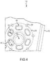
- the heat transfer augmentors 204 are shown to be surrounding the stud 200, the present disclosure may be applied to a heat transfer augmentor 204 in any location, such as in a rail or any other augmented section.
- the liner and shell assembly 130 may further include effusion holes 206 extending through the panel 150.
- the effusion holes 206 may include panel effusion holes 208 which extend through the panel 150 alone, and heat transfer augmentor effusion holes, or pin effusion holes 210 which may each extend through the panel 150 and a sidewall portion of a respective heat transfer augmentor 204.
- the effusion holes 206 may port a cooling fluid such as compressed gas from an area 205 between the panel 150 and the shell 152 into the combustion chamber 128.
- the augmentor effusion holes 210 may be designed to avoid interacting with the panel effusion holes 208, and vice versa.
- this design may interact with main panel effusion holes 201, such that the main panel effusion holes 201 may be shifted or placed away from another effusion hole 208, which may result in reduction in temperature. Heat may be transferred from the panel 150 to the compressed gas flowing through the effusion holes 206, thus cooling the panel 150. Impingement holes 207 in the shell 152 introduce the cooling fluid to gap 205.
- the heat transfer augmentors 204 may have an oblong shape.
- the heat transfer augmentors 204 may have a height 212 extending from the shell 152 to the panel 150, a length 214 extending in a direction from the respective heat transfer augmentor 204 to the stud 200, and a width 216 extending in a direction perpendicular to the length 214 and the height 212.
- the width 216 may be greater than the length 214 to facilitate the augmentor effusion holes 210 extending through the portion of the respective heat transfer augmentors 204.
- Pin effusion holes 210 may have an inlet 226 oriented on the heat transfer augmentor 204 and an outlet 228 located on the panel 150 within the combustion chamber 128. By forming the pin effusion holes 210, a distance 232 between the outlet 228 of the pin effusion hole 210 and an outlet 230 of the panel effusion hole 208 may be reduced. The reduced distance 232 may result in improved cooling of the panel 150 by more evenly distributing heat from the panel 150.
- the pin effusion hole 210 may form an angle 224 with a plane defined by a surface 233 of the panel 150.
- the angle 224 may result in the outlet 228 of the pin effusion hole 210 being aligned with the stud 200. Stated differently, the outlet 228 of the pin effusion hole 210 may at least partially overlap with a projection 234 of the stud 200 through the panel 150.
- the angle 224 may be, for example, between 1 degree and 89 degrees, between 10 degrees and 80 degrees, between 15 degrees and 75 degrees, or about 20 degrees. Where used in this context, the term "about” refers to the referenced value plus or minus 10 percent.
- the panel 150 may include multiple layers.
- the panel 150 may include a metal alloy layer 218, a bond coating 220, and a thermal coating 222.
- the bond coating 220 may bond the thermal coating 222 to the metal alloy layer 218.
- the thermal coating 222 may include a ceramic or other material that is resistant to heat and may protect the bond coating 220 and the alloy 218 from the relatively great temperatures within the combustion chamber 128.
- the heat transfer augmentors 204 may include multiple heat transfer augmentors.
- the pin effusion holes 210 may include multiple pin effusion holes 210.
- the quantity of pin effusion holes 210 may be equal to the quantity of heat transfer augmentors 204.
- references to "one embodiment”, “an embodiment”, “various embodiments”, etc. indicate that the embodiment described may include a particular feature, structure, or characteristic, but every embodiment may not necessarily include the particular feature, structure, or characteristic. Moreover, such phrases are not necessarily referring to the same embodiment. Further, when a particular feature, structure, or characteristic is described in connection with an embodiment, it is submitted that it is within the knowledge of one skilled in the art to affect such feature, structure, or characteristic in connection with other embodiments whether or not explicitly described. After reading the description, it will be apparent to one skilled in the relevant art(s) how to implement the disclosure in alternative embodiments.
Abstract
Description
- The present disclosure relates generally to gas turbine engines and, more particularly, to a combustor liner of a combustor section of a gas turbine engine having pin effusion holes extending through a panel and a portion of a respective heat transfer augmentor.
- Gas turbine engines include compressor sections to compress an airflow, combustor sections that combine the airflow with fuel for combustion and generate exhaust, and turbine sections that convert the exhaust into torque to drive the compressor sections. The combustor sections may include a combustor liner which may include an outer shell and an inner panel. One or more heat transfer augmentor may at least partially define a gap between the shell and the panel, and a stud may be used to couple the shell to the panel. It may be desirable to reduce a temperature of the panel during combustion in the combustor section. Effusion holes may extend through the panel to provide such cooling.
- Described herein is a gas turbine engine component having a first surface in communication with a core airflow. The gas turbine engine component further includes a second surface, different than the first surface, for cooling the first surface. The gas turbine engine component further includes a heat transfer augmentor extending from the second surface. The gas turbine engine component further includes a heat transfer augmentor effusion hole extending through the gas turbine engine component from a sidewall of the heat transfer augmentor to the first surface.
- Any of the foregoing embodiments may further include a stud configured to secure a second gas turbine engine component to the gas turbine engine component, wherein the heat transfer augmentor has a height extending from the first surface to the second surface, a length extending in a direction from the heat transfer augmentor to the stud, and a width that is greater than the length.
- Any of the foregoing embodiments may further include a stud configured to secure a second gas turbine engine component to the gas turbine engine component, wherein the heat transfer augmentor includes multiple heat transfer augmentors surrounding the stud.
- In any of the foregoing embodiments, the heat transfer augmentor effusion hole includes multiple effusion holes each extending through the first surface and portions of respective heat transfer augmentors.
- In any of the foregoing embodiments, the heat transfer augmentor effusion hole has an inlet located on the heat transfer augmentor and an outlet in the combustion chamber.
- Any of the foregoing embodiments may further include a stud configured to secure a second gas turbine engine component to the gas turbine engine component, wherein the outlet is located at a location aligned with the stud.
- Any of the foregoing embodiments may further include at least one panel effusion hole extending through the gas turbine engine component from the second surface to the the first surface.
- In any of the foregoing embodiments, the heat transfer augmentor effusion hole extends at an angle relative to a plane defined by a surface of the first surface.
- Also disclosed is a combustor panel for a gas turbine engine, the combustor panel including a first surface configured to at least partially define a combustion chamber. The combustor panel further includes a second surface, different than the first surface, for cooling the first surface. The combustor panel further includes a heat transfer augmentor configured to extend from the second surface. The combustor panel further includes a heat transfer augmentor effusion hole extending through the combustor panel from a sidewall of the heat transfer augmentor to the first surface.
- In any of the foregoing embodiments, the heat transfer augmentor includes at least one of a stub, a pin, or a rail.
- In any of the foregoing embodiments, the heat transfer augmentor has an oblong cross-section.
- In any of the foregoing embodiments, the heat transfer augmentor effusion hole includes multiple effusion holes each extending through respective heat transfer augmentors to the first surface.
- In any of the foregoing embodiments, the heat transfer augmentor effusion hole has an inlet located on the heat transfer augmentor and an outlet in the combustion chamber.
- Any of the foregoing embodiments may further include a stud configured to secure a second gas turbine engine component to the gas turbine engine component, wherein the outlet is located at a location aligned with the stud.
- Any of the foregoing embodiments may further include at least one panel effusion hole extending through the gas turbine engine component from the second surface to the the first surface.
- In any of the foregoing embodiments, the heat transfer augmentor effusion hole extends at an angle relative to a plane defined by a surface of the first surface.
- Any of the foregoing embodiments may further include a stud configured to secure a second gas turbine engine component to the gas turbine engine component, wherein the heat transfer augmentor has a height extending from the first surface to the second surface, a length extending in a direction from the heat transfer augmentor to the stud, and a width that is greater than the length.
- Any of the foregoing embodiments may further include a stud configured to secure a second gas turbine engine component to the gas turbine engine component, wherein the heat transfer augmentor includes multiple heat transfer augmentors surrounding the stud.
- Also disclosed is a combustor liner for use in a combustor section of a gas turbine engine, the combustor liner including a panel configured to at least partially define a combustion chamber. The combustor liner may further include a shell. The combustor liner may further include a heat transfer augmentor configured to extend from the panel to the shell to at least partially define a gap between the panel and the shell. The combustor liner may further include a pin effusion hole extending through the panel and a portion of the heat transfer augmentor to port a compressed gas through the panel and the portion of the heat transfer augmentor to the combustion chamber.
- Any of the foregoing embodiments may further include a stud configured to couple the panel to the shell, wherein the heat transfer augmentor has a height extending from the panel to the shell, a length extending in a direction from the heat transfer augmentor to the stud, and a width that is greater than the length.
- The foregoing features and elements are to be combined in various combinations without exclusivity, unless expressly indicated otherwise. These features and elements as well as the operation thereof will become more apparent in light of the following description and the accompanying drawings. It should be understood, however, the following description and drawings are intended to be exemplary in nature and non-limiting.
- The subject matter of the present disclosure is particularly pointed out and distinctly claimed in the concluding portion of the specification. A more complete understanding of the present disclosure, however, is best be obtained by referring to the detailed description and claims when considered in connection with the drawing figures, wherein like numerals denote like elements.
-
FIG. 1 is a cross-sectional view of an exemplary gas turbine engine, in accordance with various embodiments; -
FIG. 2 is a cross-sectional view of a portion of a combustor section of the gas turbine engine ofFIG. 1 , in accordance with various embodiments; -
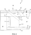
FIG. 3 illustrates a portion of a combustor liner of the combustor section ofFIG. 2 , in accordance with various embodiments; -
FIG. 4 illustrates the combustor liner ofFIG. 3 , in accordance with various embodiments; and -
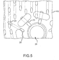
FIG. 5 illustrates a panel of the combustor liner ofFIG. 3 , in accordance with various embodiments. - The detailed description of exemplary embodiments herein makes reference to the accompanying drawings, which show exemplary embodiments by way of illustration and their best mode. While these exemplary embodiments are described in sufficient detail to enable those skilled in the art to practice the inventions, it should be understood that other embodiments may be realized and that logical, chemical and mechanical changes may be made without departing from the spirit and scope of the inventions. Thus, the detailed description herein is presented for purposes of illustration only and not of limitation. For example, the steps recited in any of the method or process descriptions may be executed in any order and are not necessarily limited to the order presented. Furthermore, any reference to singular includes plural embodiments, and any reference to more than one component or step may include a singular embodiment or step. Also, any reference to attached, fixed, connected or the like may include permanent, removable, temporary, partial, full and/or any other possible attachment option. Additionally, any reference to without contact (or similar phrases) may also include reduced contact or minimal contact. Where used herein, the phrase "at least one of A or B" can include any of "A" only, "B" only, or "A and B."
- With reference to
FIG. 1 , agas turbine engine 20 is provided. As used herein, "aft" refers to the direction associated with the tail (e.g., the back end) of an aircraft, or generally, to the direction of exhaust of the gas turbine engine. As used herein, "forward" refers to the direction associated with the nose (e.g., the front end) of an aircraft, or generally, to the direction of flight or motion. As utilized herein, radially inward refers to the negative R direction and radially outward refers to the R direction. An A-R-C axis is shown throughout the drawings to illustrate the relative position of various components. - The
gas turbine engine 20 may be a two-spool turbofan that generally incorporates afan section 22, acompressor section 24, acombustor section 26 and aturbine section 28. In operation, thefan section 22 drives air along a bypass flow-path B while thecompressor section 24 drives air along a core flow-path C for compression and communication into thecombustor section 26 then expansion through theturbine section 28. Although depicted as a turbofangas turbine engine 20 herein, it should be understood that the concepts described herein are not limited to use with turbofans as the teachings may be applied to other types of turbine engines including three-spool architectures, geared turbofan architectures, and turboshaft or industrial gas turbines with one or more spools. - The
gas turbine engine 20 generally comprises alow speed spool 30 and ahigh speed spool 32 mounted for rotation about an engine central longitudinal axis X-X' relative to an enginestatic structure 36 viaseveral bearing systems 38, 38-1, and 38-2. It should be understood that various bearingsystems 38 at various locations may alternatively or additionally be provided, including for example, the bearingsystem 38, the bearing system 38-1, and the bearing system 38-2. - The
low speed spool 30 generally includes aninner shaft 40 that interconnects afan 42, a low pressure (or first)compressor section 44 and a low pressure (or second)turbine section 46. Theinner shaft 40 is connected to thefan 42 through a gearedarchitecture 48 that can drive the fan shaft 98, and thus thefan 42, at a lower speed than thelow speed spool 30. The gearedarchitecture 48 includes agear assembly 60 enclosed within agear diffuser case 62. Thegear assembly 60 couples theinner shaft 40 to a rotating fan structure. - The
high speed spool 32 includes anouter shaft 50 that interconnects a high pressure (or second)compressor section 52 and the high pressure (or first)turbine section 54. Acombustor 56 is located between thehigh pressure compressor 52 and thehigh pressure turbine 54. Amid-turbine frame 57 of the enginestatic structure 36 is located generally between thehigh pressure turbine 54 and thelow pressure turbine 46. Themid-turbine frame 57 supports one ormore bearing systems 38 in theturbine section 28. Theinner shaft 40 and theouter shaft 50 are concentric and rotate via the bearingsystems 38 about the engine central longitudinal axis X-X', which is collinear with their longitudinal axes. As used herein, a "high pressure" compressor or turbine experiences a higher pressure than a corresponding "low pressure" compressor or turbine. - The core airflow C is compressed by the low
pressure compressor section 44 then thehigh pressure compressor 52, mixed and burned with fuel in thecombustor 56, then expanded over thehigh pressure turbine 54 and thelow pressure turbine 46. Themid-turbine frame 57 includesairfoils 59 which are in the core airflow path. Theturbines low speed spool 30 andhigh speed spool 32 in response to the expansion. - The
gas turbine engine 20 is a high-bypass ratio geared aircraft engine. The bypass ratio of thegas turbine engine 20 may be greater than about six. The bypass ratio of thegas turbine engine 20 may also be greater than ten. The gearedarchitecture 48 may be an epicyclic gear train, such as a star gear system (sun gear in meshing engagement with a plurality of star gears supported by a carrier and in meshing engagement with a ring gear) or other gear system. The gearedarchitecture 48 may have a gear reduction ratio of greater than about 2.3 and thelow pressure turbine 46 may have a pressure ratio that is greater than about five. The diameter of thefan 42 may be significantly larger than that of the lowpressure compressor section 44, and thelow pressure turbine 46 may have a pressure ratio that is greater than about five. The pressure ratio of thelow pressure turbine 46 is measured prior to an inlet of thelow pressure turbine 46 as related to the pressure at the outlet of thelow pressure turbine 46. It should be understood, however, that the above parameters are exemplary of various embodiments of a suitable geared architecture engine and that the present disclosure contemplates other turbine engines including direct drive turbofans. - The next generation turbofan engines are designed for higher efficiency and use higher pressure ratios and higher temperatures in the
high pressure compressor 52 than are conventionally experienced. These higher operating temperatures and pressure ratios create operating environments that cause thermal loads that are higher than the thermal loads conventionally experienced, which may shorten the operational life of current components. - In various embodiments and referring to
FIG. 2 , thecombustor section 26 may include an annular combustor 132. The annular combustor 132 may includemultiple fuel nozzles 124, which each include their owntrim valve 134. In various embodiments, eachfuel nozzle 124 delivers fuel to a respective section of thecombustion chamber 128. Thefuel nozzles 124 may be arranged circumferentially around an axis within a combustor 132. Thefuel nozzles 124 may include stems 136 that extend from adiffuser case 118 to openings. - Although a single fuel nozzle 124 (and other components) is shown in the drawings, one skilled in the art will realize that the
combustor section 26 may include multiple openings circumferentially around thecombustor section 26 that receivefuel nozzles 124. - The
combustor section 26 may further include adiffuser case 118. Thediffuser case 118 surrounds or encloses acombustor liner 130. Thecombustor liner 130 may partially define acombustion chamber 128. Afuel source 125 provides fuel to thefuel nozzle 124 for delivery to thecombustion chamber 128. Thefuel nozzle 124 extends through an aperture 121 in thediffuser case 118. An end of thefuel nozzle 124 may be arranged at aninlet 126 of thecombustion chamber 128. A swirler 127 (which may include a hole for the fuel nozzle 124) may provide desired airflow motion from thecompressor section 24 ofFIG. 1 to achieve a desired air/fuel mixture. One or more of the liner andshell assemblies 130 typically include one or more igniters used to begin combustion of the air/fuel mixture. - The
diffuser case 118 and thecombustor liner 130 may define anouter shroud 156 and aninner shroud 154 therebetween. In various embodiments, air or another compressed gas may flow through at least one of theinner shroud 154 or theouter shroud 156. In various embodiments, thefuel nozzle 124 may extend through theouter shroud 156 and may be extended into theinner shroud 154. Theinner shroud 154 and theouter shroud 156 may each be referred to as adiffuser chamber - The liner and
shell assembly 130 may include apanel 150 and ashell 152. In various embodiments, theshell 152 may be directly or indirectly coupled to thepanel 150 to resist movement of theshell 152 relative to thepanel 150. Thepanel 150 has a hot side that may at least partially define thecombustion chamber 128, and a cold side facing theshell 152. Theshell 152 may be located between theouter shroud 156 and thepanel 150, or between theinner shroud 154 and thepanel 150. - Referring now to
FIGS. 3 ,4 , and5 , the liner andshell assembly 130 may include astud 200 that couples theshell 152 to thepanel 150 using awasher 202 and a fastener (not shown). The liner andshell assembly 130 may further include a plurality ofheat transfer augmentors 204. Theheat transfer augmentors 204 may extend between thepanel 150 and the shell and may include any heat transfer augmentor component, such as a stand-off pin. Theheat transfer augmentors 204 may extend from thepanel 150 to theshell 152 and may resist movement of thepanel 150 towards theshell 152. In that regard, theheat transfer augmentors 204 may form agap 205 between thepanel 150 and theshell 152. Although theheat transfer augmentors 204 are shown to be surrounding thestud 200, the present disclosure may be applied to aheat transfer augmentor 204 in any location, such as in a rail or any other augmented section. - The liner and
shell assembly 130 may further include effusion holes 206 extending through thepanel 150. The effusion holes 206 may include panel effusion holes 208 which extend through thepanel 150 alone, and heat transfer augmentor effusion holes, or pin effusion holes 210 which may each extend through thepanel 150 and a sidewall portion of a respectiveheat transfer augmentor 204. The effusion holes 206 may port a cooling fluid such as compressed gas from anarea 205 between thepanel 150 and theshell 152 into thecombustion chamber 128. The augmentor effusion holes 210 may be designed to avoid interacting with the panel effusion holes 208, and vice versa. For example, this design may interact with main panel effusion holes 201, such that the main panel effusion holes 201 may be shifted or placed away from anothereffusion hole 208, which may result in reduction in temperature. Heat may be transferred from thepanel 150 to the compressed gas flowing through the effusion holes 206, thus cooling thepanel 150. Impingement holes 207 in theshell 152 introduce the cooling fluid togap 205. - To facilitate the heat transfer augmentor effusion holes 210 extending through the portions of the respective
heat transfer augmentors 204, theheat transfer augmentors 204 may have an oblong shape. In particular, theheat transfer augmentors 204 may have aheight 212 extending from theshell 152 to thepanel 150, alength 214 extending in a direction from the respectiveheat transfer augmentor 204 to thestud 200, and awidth 216 extending in a direction perpendicular to thelength 214 and theheight 212. Thewidth 216 may be greater than thelength 214 to facilitate the augmentor effusion holes 210 extending through the portion of the respectiveheat transfer augmentors 204. - Pin effusion holes 210 may have an
inlet 226 oriented on theheat transfer augmentor 204 and anoutlet 228 located on thepanel 150 within thecombustion chamber 128. By forming the pin effusion holes 210, adistance 232 between theoutlet 228 of thepin effusion hole 210 and anoutlet 230 of thepanel effusion hole 208 may be reduced. The reduceddistance 232 may result in improved cooling of thepanel 150 by more evenly distributing heat from thepanel 150. - The
pin effusion hole 210 may form anangle 224 with a plane defined by asurface 233 of thepanel 150. Theangle 224 may result in theoutlet 228 of thepin effusion hole 210 being aligned with thestud 200. Stated differently, theoutlet 228 of thepin effusion hole 210 may at least partially overlap with a projection 234 of thestud 200 through thepanel 150. Theangle 224 may be, for example, between 1 degree and 89 degrees, between 10 degrees and 80 degrees, between 15 degrees and 75 degrees, or about 20 degrees. Where used in this context, the term "about" refers to the referenced value plus or minus 10 percent. - The
panel 150 may include multiple layers. In particular, thepanel 150 may include ametal alloy layer 218, abond coating 220, and athermal coating 222. Thebond coating 220 may bond thethermal coating 222 to themetal alloy layer 218. Thethermal coating 222 may include a ceramic or other material that is resistant to heat and may protect thebond coating 220 and thealloy 218 from the relatively great temperatures within thecombustion chamber 128. - In various embodiments, the
heat transfer augmentors 204 may include multiple heat transfer augmentors. Likewise, the pin effusion holes 210 may include multiple pin effusion holes 210. In various embodiments, the quantity of pin effusion holes 210 may be equal to the quantity ofheat transfer augmentors 204. - Benefits, other advantages, and solutions to problems have been described herein with regard to specific embodiments. Furthermore, the connecting lines shown in the various figures contained herein are intended to represent exemplary functional relationships and/or physical couplings between the various elements. It should be noted that many alternative or additional functional relationships or physical connections may be present in a practical system. However, the benefits, advantages, solutions to problems, and any elements that may cause any benefit, advantage, or solution to occur or become more pronounced are not to be construed as critical, required, or essential features or elements of the inventions. The scope of the invention is accordingly to be limited by nothing other than the appended claims, in which reference to an element in the singular is not intended to mean "one and only one" unless explicitly so stated, but rather "one or more." Moreover, where a phrase similar to "at least one of A, B, or C" is used in the claims, it is intended that the phrase be interpreted to mean that A alone may be present in an embodiment, B alone may be present in an embodiment, C alone may be present in an embodiment, or that any combination of the elements A, B and C may be present in a single embodiment; for example, A and B, A and C, B and C, or A and B and C. Different cross-hatching is used throughout the figures to denote different parts but not necessarily to denote the same or different materials.
- Systems, methods and apparatus are provided herein. In the detailed description herein, references to "one embodiment", "an embodiment", "various embodiments", etc., indicate that the embodiment described may include a particular feature, structure, or characteristic, but every embodiment may not necessarily include the particular feature, structure, or characteristic. Moreover, such phrases are not necessarily referring to the same embodiment. Further, when a particular feature, structure, or characteristic is described in connection with an embodiment, it is submitted that it is within the knowledge of one skilled in the art to affect such feature, structure, or characteristic in connection with other embodiments whether or not explicitly described. After reading the description, it will be apparent to one skilled in the relevant art(s) how to implement the disclosure in alternative embodiments.
- Furthermore, no element, component, or method step in the present disclosure is intended to be dedicated to the public regardless of whether the element, component, or method step is explicitly recited in the claims. No claim element herein is to be construed under the provisions of 35 U.S.C. 112(f), unless the element is expressly recited using the phrase "means for." As used herein, the terms "comprises", "comprising", or any other variation thereof, are intended to cover a non-exclusive inclusion, such that a process, method, article, or apparatus that comprises a list of elements does not include only those elements but may include other elements not expressly listed or inherent to such process, method, article, or apparatus.
Claims (15)
- A gas turbine engine component comprising:a first surface in communication with a core airflow;a second surface, different than the first surface, for cooling the first surface;a heat transfer augmentor extending from the second surface; anda heat transfer augmentor effusion hole extending through the gas turbine engine component from a sidewall of the heat transfer augmentor to the first surface.
- The gas turbine engine component of claim 1, further comprising a stud configured to secure a second gas turbine engine component to the gas turbine engine component, wherein the heat transfer augmentor has a height extending from the first surface to the second surface, a length extending in a direction from the heat transfer augmentor to the stud, and a width that is greater than the length.
- The gas turbine engine component of claim 1 or 2, further comprising a stud configured to secure a second gas turbine engine component to the gas turbine engine component, wherein the heat transfer augmentor includes multiple heat transfer augmentors surrounding the stud.
- The gas turbine engine component of claim 3, wherein the heat transfer augmentor effusion hole includes multiple effusion holes each extending through the first surface and portions of respective heat transfer augmentors.
- The gas turbine engine component of any preceding claim, wherein the heat transfer augmentor effusion hole has an inlet located on the heat transfer augmentor and an outlet in the combustion chamber, optionally further comprising a stud configured to secure a second gas turbine engine component to the gas turbine engine component, wherein the outlet is located at a location aligned with the stud.
- The gas turbine engine component of any preceding claim, further comprising at least one panel effusion hole extending through the gas turbine engine component from the second surface to the first surface.
- The gas turbine engine component of any preceding claim, wherein the heat transfer augmentor effusion hole extends at an angle relative to a plane defined by a surface of the first surface.
- A combustor panel for a gas turbine engine, the combustor panel comprising:a first surface configured to at least partially define a combustion chamber;a second surface, different than the first surface, for cooling the first surface;a heat transfer augmentor configured to extend from the second surface; anda heat transfer augmentor effusion hole extending through the combustor panel from a sidewall of the heat transfer augmentor to the first surface.
- The combustor panel of claim 8, wherein the heat transfer augmentor includes at least one of a stub, a pin, or a rail.
- The combustor panel of claim 8 or 9, wherein the heat transfer augmentor has an oblong cross-section.
- The combustor panel of claim 10, wherein the heat transfer augmentor effusion hole includes multiple effusion holes each extending through respective heat transfer augmentors to the first surface.
- The combustor panel of claim 9, 10 or 11, wherein the heat transfer augmentor effusion hole has an inlet located on the heat transfer augmentor and an outlet in the combustion chamber, optionally further comprising a stud configured to secure a second gas turbine engine component to the gas turbine engine component, wherein the outlet is located at a location aligned with the stud.
- The combustor panel of any of claims 9 to 12, wherein:the combustor panel further comprises at least one panel effusion hole extending through the gas turbine engine component from the second surface to the first surface;the heat transfer augmentor effusion hole extends at an angle relative to a plane defined by a surface of the first surface;the combustor panel further comprises a stud configured to secure a second gas turbine engine component to the gas turbine engine component, wherein the heat transfer augmentor has a height extending from the first surface to the second surface, a length extending in a direction from the heat transfer augmentor to the stud, and a width that is greater than the length; and/orthe combustor panel further comprises a stud configured to secure a second gas turbine engine component to the gas turbine engine component, wherein the heat transfer augmentor includes multiple heat transfer augmentors surrounding the stud.
- A combustor liner for use in a combustor section of a gas turbine engine, the combustor liner comprising:a panel configured to at least partially define a combustion chamber;a shell;a heat transfer augmentor configured to extend from the panel to the shell to at least partially define a gap between the panel and the shell; anda pin effusion hole extending through the panel and a portion of the heat transfer augmentor to port a compressed gas through the panel and the portion of the heat transfer augmentor to the combustion chamber.
- The combustor liner of claim 14, further comprising a stud configured to couple the panel to the shell, wherein the heat transfer augmentor has a height extending from the panel to the shell, a length extending in a direction from the heat transfer augmentor to the stud, and a width that is greater than the length.
Applications Claiming Priority (2)
| Application Number | Priority Date | Filing Date | Title |
|---|---|---|---|
| US201962788613P | 2019-01-04 | 2019-01-04 | |
| US16/725,116 US11209162B2 (en) | 2019-01-04 | 2019-12-23 | Combustor panel stud cooling effusion through heat transfer augmentors |
Publications (1)
| Publication Number | Publication Date |
|---|---|
| EP3677836A1 true EP3677836A1 (en) | 2020-07-08 |
Family
ID=69137808
Family Applications (1)
| Application Number | Title | Priority Date | Filing Date |
|---|---|---|---|
| EP20150376.0A Pending EP3677836A1 (en) | 2019-01-04 | 2020-01-06 | Combustor panel stud cooling by effusion through heat transfer augmentors |
Country Status (2)
| Country | Link |
|---|---|
| US (1) | US11209162B2 (en) |
| EP (1) | EP3677836A1 (en) |
Citations (7)
| Publication number | Priority date | Publication date | Assignee | Title |
|---|---|---|---|---|
| JP2014148938A (en) * | 2013-02-01 | 2014-08-21 | Siemens Ag | Film-cooled turbine blade for turbomachine |
| WO2015050592A2 (en) * | 2013-06-14 | 2015-04-09 | United Technologies Corporation | Gas turbine engine combustor liner panel |
| US20170176006A1 (en) * | 2015-12-16 | 2017-06-22 | Rolls-Royce Deutschland Ltd & Co Kg | Wall of a structural component, in particular of a gas turbine combustion chamber wall, to be cooled by means of cooling air |
| EP3239462A1 (en) * | 2016-04-26 | 2017-11-01 | General Electric Company | Airfoil for a turbine engine |
| EP3315865A2 (en) * | 2016-10-26 | 2018-05-02 | United Technologies Corporation | Combustor liner panel with a multiple of heat transfer augmentors for a gas turbine engine combustor |
| EP3453969A2 (en) * | 2017-09-08 | 2019-03-13 | United Technologies Corporation | Cooling configurations for combustor attachment features |
| EP3524885A1 (en) * | 2018-02-09 | 2019-08-14 | United Technologies Corporation | Combustor panel standoff pin |
Family Cites Families (14)
| Publication number | Priority date | Publication date | Assignee | Title |
|---|---|---|---|---|
| GB2373319B (en) | 2001-03-12 | 2005-03-30 | Rolls Royce Plc | Combustion apparatus |
| GB201222311D0 (en) * | 2012-12-12 | 2013-01-23 | Rolls Royce Plc | A combusiton chamber |
| WO2015122950A2 (en) * | 2013-11-21 | 2015-08-20 | United Technologies Corporation | Turbine engine multi-walled structure with internal cooling element(s) |
| US9625152B2 (en) | 2014-06-03 | 2017-04-18 | Pratt & Whitney Canada Corp. | Combustor heat shield for a gas turbine engine |
| US20180292089A1 (en) * | 2017-04-05 | 2018-10-11 | United Technologies Corporation | Combustor attachment cooling |
| US10731562B2 (en) * | 2017-07-17 | 2020-08-04 | Raytheon Technologies Corporation | Combustor panel standoffs with cooling holes |
| US10247419B2 (en) * | 2017-08-01 | 2019-04-02 | United Technologies Corporation | Combustor liner panel with a multiple of heat transfer ribs for a gas turbine engine combustor |
| US10670273B2 (en) * | 2017-09-08 | 2020-06-02 | Raytheon Technologies Corporation | Cooling configurations for combustor attachment features |
| US10619857B2 (en) * | 2017-09-08 | 2020-04-14 | United Technologies Corporation | Cooling configuration for combustor attachment feature |
| US10670275B2 (en) * | 2017-09-08 | 2020-06-02 | Raytheon Technologies Corporation | Cooling configurations for combustor attachment features |
| US20190078786A1 (en) * | 2017-09-08 | 2019-03-14 | United Technologies Corporation | Cooling configurations for combustor attachment features |
| US20190186740A1 (en) * | 2017-12-19 | 2019-06-20 | United Technologies Corporation | Apparatus and method for mitigating particulate accumulation on a component of a gas turbine engine |
| US11561007B2 (en) * | 2019-01-04 | 2023-01-24 | United Technologies Corporation | Combustor cooling panel stud |
| US11391460B2 (en) * | 2019-07-16 | 2022-07-19 | Raytheon Technologies Corporation | Effusion cooling for dilution/quench hole edges in combustor liner panels |
-
2019
- 2019-12-23 US US16/725,116 patent/US11209162B2/en active Active
-
2020
- 2020-01-06 EP EP20150376.0A patent/EP3677836A1/en active Pending
Patent Citations (7)
| Publication number | Priority date | Publication date | Assignee | Title |
|---|---|---|---|---|
| JP2014148938A (en) * | 2013-02-01 | 2014-08-21 | Siemens Ag | Film-cooled turbine blade for turbomachine |
| WO2015050592A2 (en) * | 2013-06-14 | 2015-04-09 | United Technologies Corporation | Gas turbine engine combustor liner panel |
| US20170176006A1 (en) * | 2015-12-16 | 2017-06-22 | Rolls-Royce Deutschland Ltd & Co Kg | Wall of a structural component, in particular of a gas turbine combustion chamber wall, to be cooled by means of cooling air |
| EP3239462A1 (en) * | 2016-04-26 | 2017-11-01 | General Electric Company | Airfoil for a turbine engine |
| EP3315865A2 (en) * | 2016-10-26 | 2018-05-02 | United Technologies Corporation | Combustor liner panel with a multiple of heat transfer augmentors for a gas turbine engine combustor |
| EP3453969A2 (en) * | 2017-09-08 | 2019-03-13 | United Technologies Corporation | Cooling configurations for combustor attachment features |
| EP3524885A1 (en) * | 2018-02-09 | 2019-08-14 | United Technologies Corporation | Combustor panel standoff pin |
Also Published As
| Publication number | Publication date |
|---|---|
| US11209162B2 (en) | 2021-12-28 |
| US20200217507A1 (en) | 2020-07-09 |
Similar Documents
| Publication | Publication Date | Title |
|---|---|---|
| EP3404329B1 (en) | Combustor panel endrail interface | |
| EP3066318B1 (en) | Inner diffuser case for a gas turbine engine | |
| US10837635B2 (en) | Fuel swirler with anti-rotation features | |
| US20190285276A1 (en) | Castellated combustor panels | |
| EP3633269B1 (en) | Combustor panels with film cooling hole pattern | |
| US20160186571A1 (en) | Mixing plenum for spoked rotors | |
| EP3677838A1 (en) | Combustor cooling panel stud | |
| US10816204B2 (en) | Heat shield with axial retention lock | |
| EP3042060A1 (en) | Combustor bulkhead heat shield | |
| US11175041B2 (en) | Systems and methods for combustor panel | |
| US20220364728A1 (en) | Effusion cooling for dilution/quench hole edges in combustor liner panels | |
| US20230228419A1 (en) | Extended bulkhead panel | |
| EP3677837B1 (en) | Combustor cooling panel with flow guide | |
| EP3677836A1 (en) | Combustor panel stud cooling by effusion through heat transfer augmentors | |
| US11719439B2 (en) | Panel burn through tolerant shell design |
Legal Events
| Date | Code | Title | Description |
|---|---|---|---|
| PUAI | Public reference made under article 153(3) epc to a published international application that has entered the european phase |
Free format text: ORIGINAL CODE: 0009012 |
|
| STAA | Information on the status of an ep patent application or granted ep patent |
Free format text: STATUS: THE APPLICATION HAS BEEN PUBLISHED |
|
| AK | Designated contracting states |
Kind code of ref document: A1 Designated state(s): AL AT BE BG CH CY CZ DE DK EE ES FI FR GB GR HR HU IE IS IT LI LT LU LV MC MK MT NL NO PL PT RO RS SE SI SK SM TR |
|
| AX | Request for extension of the european patent |
Extension state: BA ME |
|
| STAA | Information on the status of an ep patent application or granted ep patent |
Free format text: STATUS: REQUEST FOR EXAMINATION WAS MADE |
|
| 17P | Request for examination filed |
Effective date: 20210111 |
|
| RBV | Designated contracting states (corrected) |
Designated state(s): AL AT BE BG CH CY CZ DE DK EE ES FI FR GB GR HR HU IE IS IT LI LT LU LV MC MK MT NL NO PL PT RO RS SE SI SK SM TR |
|
| RAP1 | Party data changed (applicant data changed or rights of an application transferred) |
Owner name: RAYTHEON TECHNOLOGIES CORPORATION |
|
| RAP3 | Party data changed (applicant data changed or rights of an application transferred) |
Owner name: RTX CORPORATION |