EP3534034A1 - Hourglass type air spring assembly - Google Patents
Hourglass type air spring assembly Download PDFInfo
- Publication number
- EP3534034A1 EP3534034A1 EP18870891.1A EP18870891A EP3534034A1 EP 3534034 A1 EP3534034 A1 EP 3534034A1 EP 18870891 A EP18870891 A EP 18870891A EP 3534034 A1 EP3534034 A1 EP 3534034A1
- Authority
- EP
- European Patent Office
- Prior art keywords
- plate
- end plate
- elastomer
- sand clock
- spring assembly
- Prior art date
- Legal status (The legal status is an assumption and is not a legal conclusion. Google has not performed a legal analysis and makes no representation as to the accuracy of the status listed.)
- Withdrawn
Links
- 229920001971 elastomer Polymers 0.000 claims abstract description 57
- 239000000806 elastomer Substances 0.000 claims abstract description 56
- 239000004576 sand Substances 0.000 claims abstract description 44
- 238000005192 partition Methods 0.000 claims abstract description 31
- 230000002093 peripheral effect Effects 0.000 claims description 4
- 238000009434 installation Methods 0.000 description 7
- 238000006073 displacement reaction Methods 0.000 description 5
- 230000004048 modification Effects 0.000 description 3
- 238000012986 modification Methods 0.000 description 3
- 230000008901 benefit Effects 0.000 description 2
- 230000003139 buffering effect Effects 0.000 description 2
- 238000013016 damping Methods 0.000 description 2
- 238000010586 diagram Methods 0.000 description 2
- 238000004073 vulcanization Methods 0.000 description 2
- 238000005299 abrasion Methods 0.000 description 1
- 230000008859 change Effects 0.000 description 1
- 238000005516 engineering process Methods 0.000 description 1
- 230000006872 improvement Effects 0.000 description 1
- 238000013040 rubber vulcanization Methods 0.000 description 1
Images

Classifications
-
- F—MECHANICAL ENGINEERING; LIGHTING; HEATING; WEAPONS; BLASTING
- F16—ENGINEERING ELEMENTS AND UNITS; GENERAL MEASURES FOR PRODUCING AND MAINTAINING EFFECTIVE FUNCTIONING OF MACHINES OR INSTALLATIONS; THERMAL INSULATION IN GENERAL
- F16F—SPRINGS; SHOCK-ABSORBERS; MEANS FOR DAMPING VIBRATION
- F16F9/00—Springs, vibration-dampers, shock-absorbers, or similarly-constructed movement-dampers using a fluid or the equivalent as damping medium
- F16F9/02—Springs, vibration-dampers, shock-absorbers, or similarly-constructed movement-dampers using a fluid or the equivalent as damping medium using gas only or vacuum
- F16F9/04—Springs, vibration-dampers, shock-absorbers, or similarly-constructed movement-dampers using a fluid or the equivalent as damping medium using gas only or vacuum in a chamber with a flexible wall
- F16F9/0454—Springs, vibration-dampers, shock-absorbers, or similarly-constructed movement-dampers using a fluid or the equivalent as damping medium using gas only or vacuum in a chamber with a flexible wall characterised by the assembling method or by the mounting arrangement, e.g. mounting of the membrane
-
- F—MECHANICAL ENGINEERING; LIGHTING; HEATING; WEAPONS; BLASTING
- F16—ENGINEERING ELEMENTS AND UNITS; GENERAL MEASURES FOR PRODUCING AND MAINTAINING EFFECTIVE FUNCTIONING OF MACHINES OR INSTALLATIONS; THERMAL INSULATION IN GENERAL
- F16F—SPRINGS; SHOCK-ABSORBERS; MEANS FOR DAMPING VIBRATION
- F16F13/00—Units comprising springs of the non-fluid type as well as vibration-dampers, shock-absorbers, or fluid springs
- F16F13/002—Units comprising springs of the non-fluid type as well as vibration-dampers, shock-absorbers, or fluid springs comprising at least one fluid spring
-
- F—MECHANICAL ENGINEERING; LIGHTING; HEATING; WEAPONS; BLASTING
- F16—ENGINEERING ELEMENTS AND UNITS; GENERAL MEASURES FOR PRODUCING AND MAINTAINING EFFECTIVE FUNCTIONING OF MACHINES OR INSTALLATIONS; THERMAL INSULATION IN GENERAL
- F16F—SPRINGS; SHOCK-ABSORBERS; MEANS FOR DAMPING VIBRATION
- F16F13/00—Units comprising springs of the non-fluid type as well as vibration-dampers, shock-absorbers, or fluid springs
- F16F13/04—Units comprising springs of the non-fluid type as well as vibration-dampers, shock-absorbers, or fluid springs comprising both a plastics spring and a damper, e.g. a friction damper
- F16F13/06—Units comprising springs of the non-fluid type as well as vibration-dampers, shock-absorbers, or fluid springs comprising both a plastics spring and a damper, e.g. a friction damper the damper being a fluid damper, e.g. the plastics spring not forming a part of the wall of the fluid chamber of the damper
-
- F—MECHANICAL ENGINEERING; LIGHTING; HEATING; WEAPONS; BLASTING
- F16—ENGINEERING ELEMENTS AND UNITS; GENERAL MEASURES FOR PRODUCING AND MAINTAINING EFFECTIVE FUNCTIONING OF MACHINES OR INSTALLATIONS; THERMAL INSULATION IN GENERAL
- F16F—SPRINGS; SHOCK-ABSORBERS; MEANS FOR DAMPING VIBRATION
- F16F15/00—Suppression of vibrations in systems; Means or arrangements for avoiding or reducing out-of-balance forces, e.g. due to motion
- F16F15/02—Suppression of vibrations of non-rotating, e.g. reciprocating systems; Suppression of vibrations of rotating systems by use of members not moving with the rotating systems
- F16F15/022—Suppression of vibrations of non-rotating, e.g. reciprocating systems; Suppression of vibrations of rotating systems by use of members not moving with the rotating systems using dampers and springs in combination
-
- F—MECHANICAL ENGINEERING; LIGHTING; HEATING; WEAPONS; BLASTING
- F16—ENGINEERING ELEMENTS AND UNITS; GENERAL MEASURES FOR PRODUCING AND MAINTAINING EFFECTIVE FUNCTIONING OF MACHINES OR INSTALLATIONS; THERMAL INSULATION IN GENERAL
- F16F—SPRINGS; SHOCK-ABSORBERS; MEANS FOR DAMPING VIBRATION
- F16F15/00—Suppression of vibrations in systems; Means or arrangements for avoiding or reducing out-of-balance forces, e.g. due to motion
- F16F15/02—Suppression of vibrations of non-rotating, e.g. reciprocating systems; Suppression of vibrations of rotating systems by use of members not moving with the rotating systems
- F16F15/023—Suppression of vibrations of non-rotating, e.g. reciprocating systems; Suppression of vibrations of rotating systems by use of members not moving with the rotating systems using fluid means
- F16F15/0232—Suppression of vibrations of non-rotating, e.g. reciprocating systems; Suppression of vibrations of rotating systems by use of members not moving with the rotating systems using fluid means with at least one gas spring
-
- F—MECHANICAL ENGINEERING; LIGHTING; HEATING; WEAPONS; BLASTING
- F16—ENGINEERING ELEMENTS AND UNITS; GENERAL MEASURES FOR PRODUCING AND MAINTAINING EFFECTIVE FUNCTIONING OF MACHINES OR INSTALLATIONS; THERMAL INSULATION IN GENERAL
- F16F—SPRINGS; SHOCK-ABSORBERS; MEANS FOR DAMPING VIBRATION
- F16F15/00—Suppression of vibrations in systems; Means or arrangements for avoiding or reducing out-of-balance forces, e.g. due to motion
- F16F15/02—Suppression of vibrations of non-rotating, e.g. reciprocating systems; Suppression of vibrations of rotating systems by use of members not moving with the rotating systems
- F16F15/04—Suppression of vibrations of non-rotating, e.g. reciprocating systems; Suppression of vibrations of rotating systems by use of members not moving with the rotating systems using elastic means
-
- F—MECHANICAL ENGINEERING; LIGHTING; HEATING; WEAPONS; BLASTING
- F16—ENGINEERING ELEMENTS AND UNITS; GENERAL MEASURES FOR PRODUCING AND MAINTAINING EFFECTIVE FUNCTIONING OF MACHINES OR INSTALLATIONS; THERMAL INSULATION IN GENERAL
- F16F—SPRINGS; SHOCK-ABSORBERS; MEANS FOR DAMPING VIBRATION
- F16F15/00—Suppression of vibrations in systems; Means or arrangements for avoiding or reducing out-of-balance forces, e.g. due to motion
- F16F15/02—Suppression of vibrations of non-rotating, e.g. reciprocating systems; Suppression of vibrations of rotating systems by use of members not moving with the rotating systems
- F16F15/04—Suppression of vibrations of non-rotating, e.g. reciprocating systems; Suppression of vibrations of rotating systems by use of members not moving with the rotating systems using elastic means
- F16F15/046—Suppression of vibrations of non-rotating, e.g. reciprocating systems; Suppression of vibrations of rotating systems by use of members not moving with the rotating systems using elastic means using combinations of springs of different kinds
-
- F—MECHANICAL ENGINEERING; LIGHTING; HEATING; WEAPONS; BLASTING
- F16—ENGINEERING ELEMENTS AND UNITS; GENERAL MEASURES FOR PRODUCING AND MAINTAINING EFFECTIVE FUNCTIONING OF MACHINES OR INSTALLATIONS; THERMAL INSULATION IN GENERAL
- F16F—SPRINGS; SHOCK-ABSORBERS; MEANS FOR DAMPING VIBRATION
- F16F9/00—Springs, vibration-dampers, shock-absorbers, or similarly-constructed movement-dampers using a fluid or the equivalent as damping medium
- F16F9/02—Springs, vibration-dampers, shock-absorbers, or similarly-constructed movement-dampers using a fluid or the equivalent as damping medium using gas only or vacuum
- F16F9/04—Springs, vibration-dampers, shock-absorbers, or similarly-constructed movement-dampers using a fluid or the equivalent as damping medium using gas only or vacuum in a chamber with a flexible wall
-
- F—MECHANICAL ENGINEERING; LIGHTING; HEATING; WEAPONS; BLASTING
- F16—ENGINEERING ELEMENTS AND UNITS; GENERAL MEASURES FOR PRODUCING AND MAINTAINING EFFECTIVE FUNCTIONING OF MACHINES OR INSTALLATIONS; THERMAL INSULATION IN GENERAL
- F16F—SPRINGS; SHOCK-ABSORBERS; MEANS FOR DAMPING VIBRATION
- F16F9/00—Springs, vibration-dampers, shock-absorbers, or similarly-constructed movement-dampers using a fluid or the equivalent as damping medium
- F16F9/02—Springs, vibration-dampers, shock-absorbers, or similarly-constructed movement-dampers using a fluid or the equivalent as damping medium using gas only or vacuum
- F16F9/04—Springs, vibration-dampers, shock-absorbers, or similarly-constructed movement-dampers using a fluid or the equivalent as damping medium using gas only or vacuum in a chamber with a flexible wall
- F16F9/05—Springs, vibration-dampers, shock-absorbers, or similarly-constructed movement-dampers using a fluid or the equivalent as damping medium using gas only or vacuum in a chamber with a flexible wall the flexible wall being of the rolling diaphragm type
- F16F9/052—Springs, vibration-dampers, shock-absorbers, or similarly-constructed movement-dampers using a fluid or the equivalent as damping medium using gas only or vacuum in a chamber with a flexible wall the flexible wall being of the rolling diaphragm type characterised by the bumper
-
- B—PERFORMING OPERATIONS; TRANSPORTING
- B60—VEHICLES IN GENERAL
- B60G—VEHICLE SUSPENSION ARRANGEMENTS
- B60G2204/00—Indexing codes related to suspensions per se or to auxiliary parts
- B60G2204/40—Auxiliary suspension parts; Adjustment of suspensions
- B60G2204/45—Stops limiting travel
- B60G2204/4502—Stops limiting travel using resilient buffer
-
- B—PERFORMING OPERATIONS; TRANSPORTING
- B60—VEHICLES IN GENERAL
- B60G—VEHICLE SUSPENSION ARRANGEMENTS
- B60G2206/00—Indexing codes related to the manufacturing of suspensions: constructional features, the materials used, procedures or tools
- B60G2206/01—Constructional features of suspension elements, e.g. arms, dampers, springs
- B60G2206/40—Constructional features of dampers and/or springs
- B60G2206/42—Springs
- B60G2206/424—Plunger or top retainer construction for bellows or rolling lobe type air springs
Definitions
- the invention mainly relates to the buffering and damping technology, more particularly relates to a sand clock type air spring assembly.
- the air spring assembly is widely applied in railway cars, overload vehicles and other important buffering or damping occasions.
- this spring assembly comprises an elastomer located between a pair of rigid end plates.
- the elastomer is made of rubber, and compressed by loads acted on the spring assembly.
- the sand clock type secondary spring has lower vertical rigidity at low loads, so the comfort is very good, however, at high loads, the nonlinearity of the sand clock type secondary spring results in great vertical rigidity at high loads, and seriously affects the comfort, while for some heavy haul trains, particularly for double-deck multiple unit trains, the vertical rigidity of the secondary spring is required to be very small at high loads, therefore, the existing sand clock type secondary spring cannot meet this requirement.
- the objects in the invention is in view of the abovementioned problems of the prior art, and provide a sand clock type air spring assembly, which is simple in structure, convenient to install, low in heavy-load vertical rigidity and high in comfort and stability.
- a sand clock type air spring assembly comprises an upper cover plate, an air bag, an upper end plate and a lower end plate; the periphery of the upper cover plate is connected with the periphery of the upper end plate through the air bag; a low-position sand clock elastomer and a high-position elastomer which are integrally formed are connected with each other between the upper end plate and the lower end plate, and an annular notch is formed between the low-position sand clock elastomer and the high-position elastomer, and an annular rigid partition plate matched with the annular notch is arranged in the annular notch.
- the bottom surface of the annular rigid partition plate is set as a flat surface
- the top surface of the annular rigid partition plate is formed by a section of flat surface and a section of inclined surface; the flat surface on the top part of the annular rigid partition plate is close to its periphery, and the low position of the top inclined surface of the annular rigid partition plate is close to its inner ring.
- the periphery of the annular rigid partition plate is provided with a fail-safe gap.
- the fail-safe gap is located outside of the annular notch.
- an inner cavity is provided in the centers of the low-position sand clock elastomer and the high-position elastomer, and the bottom center of the upper end plate is provided with a stop part extending to inner cavity.
- the top surface of the upper end plate is provided with a counter bore for losing weight.
- the counter bore is internally provided with spaced rib plates; the top part of the upper end plate is provided with a wearing plate which is fastened with each rib plate.
- the bottom part of the peripheral face of the upper cover plate is provided with a retaining ring; one end of the air bag is buckled with the retaining ring, and the other end is connected with the upper end plate.
- the sand clock type air spring assembly of the present invention comprises an upper cover plate, an air bag, an upper end plate and a lower end plate, the periphery of the upper cover plate is connected with the periphery of the upper end plate through the air bag; low-position sand clock elastomers and high-position elastomers which are integrally formed are connected with each other between the upper end plate and the lower end plate, and annular notches are formed between the low-position sand clock elastomers and the high-position elastomers, and annular rigid partition plates matched with the annular notches are arranged in the annular notches.
- low-position sand clock elastomers and high-position elastomers which are integrally formed constitute a serial structure which increases the elevation of the elastomer between the upper end plate and the lower end plate, thus greatly reducing the heavy-load vertical rigidity of the secondary spring and improving the comfort of the secondary spring at heavy loads; in addition, while the elevation increases, the transverse displacement of the elastomer between the upper end plate and the lower end plate is also increased; in this structure, the low-position sand clock elastomer is incompletely isolated from the high-position elastomer through the coordination of the annular rigid partition plate and the annular notch, which is arranged between the low-position sand clock elastomer and the high-position elastomer , so as to avoid the transverse deformation of the secondary spring and improve the stability of the transverse displacement of the secondary spring; in this structure, the annular rigid partition plate is coordinated with the annular notch; the structure is simple; the annular rigid partition plate will not damage
- an embodiment of the sand clock type air spring assembly in the present invention comprises an upper cover plate 1, an air bag 2, an upper end plate 3 and a lower end plate 4; the periphery of the upper cover plate 1 is connected with the periphery of the upper end plate 3 through the air bag 2; a low-position sand clock elastomer 5 and a high-position elastomer 6 which are integrally formed are connected with each other between the upper end plate 3 and the lower end plate 4, and an annular notch 7 is formed between the low-position sand clock elastomer 5 and the high-position elastomer 6, and an annular rigid partition plate 8 matched with the annular notch is arranged in the annular notch 7.
- the low-position sand clock elastomer 5 and the high-position elastomer 6 which are integrally formed constitute a serial structure which increases the elevation of the elastomer between the upper end plate 3 and the lower end plate 4, thus greatly reducing the heavy-load vertical rigidity of the secondary spring and improving the comfort of the secondary spring at heavy loads; in addition, while the elevation increases, the transverse displacement of the elastomer between the upper end plate 3 and the lower end plate 4 is also increased; in this structure, the low-position sand clock elastomer 5 is incompletely isolated from the high-position elastomer 6 through the coordination of the annular rigid partition plate 8 and the annular notch 7, which is arranged between the low-position sand clock elastomer 5 and the high-position elastomer 6, and so as to avoid the transverse deformation of the secondary spring and improve the stability of the transverse displacement of the secondary spring; in this structure, the annular rigid partition plate 8 is coordinated with the annular notch 7, and it
- the bottom surface of the annular rigid partition plate 8 is set as a flat surface, and the top surface of the annular rigid partition plate 8 is formed by a section of flat surface and a section of inclined surface; the flat surface on the top part of the annular rigid partition plate 8 is close to its periphery, and the low position of the top inclined surface of the annular rigid partition plate 8 is close to its inner ring.
- the annular rigid partition plate 8 is of wedge ring structure which is big outside and small inside, and the provision of the inclined surface makes the opposite inclined surface restrict the secondary spring during transverse displacement, so as to prevent its transverse deformation; while provision of the upper and lower flat surfaces can keep the vertical stresses of the low-position sand clock elastomers 5 and the high-position elastomers 6 uniform.
- the periphery of the annular rigid partition plate 8 is provided with a fail-safe gap 81.
- the fail-safe gap 81 effectively avoids reverse installation of the annular rigid partition plate 8 in the vulcanization process, and after vulcanization, the annular rigid partition plate 8 can also be detected whether it is installed reversely or not through observing the appearance of the secondary spring.
- the fail-safe gap 81 is located outside of the annular notch 7.
- Such setting makes the annular rigid partition plate 8 is integrally extended to the outside of the annular notch 7, and it is convenient for installation.
- an inner cavity 9 is provided in the centers of the low-position sand clock elastomer 5 and the high-position elastomer 6, and the bottom center of the upper end plate 3 is provided with a stop part 31 extending to the inner cavity 9.
- the stop part 31 ensures the overall settlement of the vehicle and keeps there is no interference between the vehicle body and the bogie at high loads and dynamic loads, etc.
- the top surface of the upper end plate 3 is provided with a counter bore 32 for losing weight.
- the provision of the counter bore 32 can reduce the weight of the spring assembly and the total weight of the system.
- the counter bore 32 is internally provided with spaced rib plates 33; the top part of the upper end plate 3 is provided with a wearing plate 10 which is fastened with each rib plate 33.
- the wearing plate 10 is mainly used for avoiding loss of the upper end plate 3, and it is fastened with the rib plate 33, good for installation.
- the bottom part of the peripheral face of the upper cover plate 1 is provided with a retaining ring 11; one end of the air bag 2 is buckled with the retaining ring 11, and the other end is connected with the upper end plate 3.
- the joint between the upper end plate 3 and the small opening of the air bag 2 is protected by rubber vulcanization, relieving the abrasion of the small opening of the air bag 2 at heavy loads, improving the useful life of the air bag 2 and the secondary spring.
Landscapes
- Engineering & Computer Science (AREA)
- General Engineering & Computer Science (AREA)
- Mechanical Engineering (AREA)
- Physics & Mathematics (AREA)
- Acoustics & Sound (AREA)
- Aviation & Aerospace Engineering (AREA)
- Fluid-Damping Devices (AREA)
Abstract
Description
- The invention mainly relates to the buffering and damping technology, more particularly relates to a sand clock type air spring assembly.
- The air spring assembly is widely applied in railway cars, overload vehicles and other important buffering or damping occasions. Usually, this spring assembly comprises an elastomer located between a pair of rigid end plates. The elastomer is made of rubber, and compressed by loads acted on the spring assembly. In the prior art, the sand clock type secondary spring has lower vertical rigidity at low loads, so the comfort is very good, however, at high loads, the nonlinearity of the sand clock type secondary spring results in great vertical rigidity at high loads, and seriously affects the comfort, while for some heavy haul trains, particularly for double-deck multiple unit trains, the vertical rigidity of the secondary spring is required to be very small at high loads, therefore, the existing sand clock type secondary spring cannot meet this requirement.
- The objects in the invention is in view of the abovementioned problems of the prior art, and provide a sand clock type air spring assembly, which is simple in structure, convenient to install, low in heavy-load vertical rigidity and high in comfort and stability.
- To solve the aforesaid problems, the following technical solutions can be adopted:
A sand clock type air spring assembly comprises an upper cover plate, an air bag, an upper end plate and a lower end plate; the periphery of the upper cover plate is connected with the periphery of the upper end plate through the air bag; a low-position sand clock elastomer and a high-position elastomer which are integrally formed are connected with each other between the upper end plate and the lower end plate, and an annular notch is formed between the low-position sand clock elastomer and the high-position elastomer, and an annular rigid partition plate matched with the annular notch is arranged in the annular notch. - As further improvement of the above technical solution:
Preferably, the bottom surface of the annular rigid partition plate is set as a flat surface, and the top surface of the annular rigid partition plate is formed by a section of flat surface and a section of inclined surface; the flat surface on the top part of the annular rigid partition plate is close to its periphery, and the low position of the top inclined surface of the annular rigid partition plate is close to its inner ring. - Preferably, the periphery of the annular rigid partition plate is provided with a fail-safe gap.
- Preferably, the fail-safe gap is located outside of the annular notch.
- Preferably, an inner cavity is provided in the centers of the low-position sand clock elastomer and the high-position elastomer, and the bottom center of the upper end plate is provided with a stop part extending to inner cavity.
- Preferably, the top surface of the upper end plate is provided with a counter bore for losing weight.
- Preferably, the counter bore is internally provided with spaced rib plates; the top part of the upper end plate is provided with a wearing plate which is fastened with each rib plate.
- Preferably, the bottom part of the peripheral face of the upper cover plate is provided with a retaining ring; one end of the air bag is buckled with the retaining ring, and the other end is connected with the upper end plate.
- Compared with the prior art, the invention has the following advantages:
The sand clock type air spring assembly of the present invention comprises an upper cover plate, an air bag, an upper end plate and a lower end plate, the periphery of the upper cover plate is connected with the periphery of the upper end plate through the air bag; low-position sand clock elastomers and high-position elastomers which are integrally formed are connected with each other between the upper end plate and the lower end plate, and annular notches are formed between the low-position sand clock elastomers and the high-position elastomers, and annular rigid partition plates matched with the annular notches are arranged in the annular notches. In this structure, low-position sand clock elastomers and high-position elastomers which are integrally formed constitute a serial structure which increases the elevation of the elastomer between the upper end plate and the lower end plate, thus greatly reducing the heavy-load vertical rigidity of the secondary spring and improving the comfort of the secondary spring at heavy loads; in addition, while the elevation increases, the transverse displacement of the elastomer between the upper end plate and the lower end plate is also increased; in this structure, the low-position sand clock elastomer is incompletely isolated from the high-position elastomer through the coordination of the annular rigid partition plate and the annular notch, which is arranged between the low-position sand clock elastomer and the high-position elastomer , so as to avoid the transverse deformation of the secondary spring and improve the stability of the transverse displacement of the secondary spring; in this structure, the annular rigid partition plate is coordinated with the annular notch; the structure is simple; the annular rigid partition plate will not damage the low-position sand clock elastomer and the high-position elastomer during installation, which improves installation convenience and ensures the completeness of the low-position sand clock elastomers and the high-position elastomers. -
-
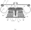
Fig. 1 is a structure diagram of the present invention. -
Fig. 2 is a top structure diagram of the upper end plate in the present invention. - 1- upper cover plate; 11- retaining ring; 2- air bag; 3- upper end plate; 31- stop part; 32-counter bore; 33- rib plate; 4- lower end plate; 5- low-position sand clock elastomer; 6-high-position elastomer; 7- annular notch; 8- annular rigid partition plate; 81- fail-safe gap; 9-inner cavity; 10- wearing plate.
- The present invention will be further clarified based on the following figures and embodiments.
- As shown in
Fig. 1 andFig. 2 , an embodiment of the sand clock type air spring assembly in the present invention comprises an upper cover plate 1, anair bag 2, anupper end plate 3 and alower end plate 4; the periphery of the upper cover plate 1 is connected with the periphery of theupper end plate 3 through theair bag 2; a low-positionsand clock elastomer 5 and a high-position elastomer 6 which are integrally formed are connected with each other between theupper end plate 3 and thelower end plate 4, and anannular notch 7 is formed between the low-positionsand clock elastomer 5 and the high-position elastomer 6, and an annularrigid partition plate 8 matched with the annular notch is arranged in theannular notch 7. In this structure, the low-positionsand clock elastomer 5 and the high-position elastomer 6 which are integrally formed constitute a serial structure which increases the elevation of the elastomer between theupper end plate 3 and thelower end plate 4, thus greatly reducing the heavy-load vertical rigidity of the secondary spring and improving the comfort of the secondary spring at heavy loads; in addition, while the elevation increases, the transverse displacement of the elastomer between theupper end plate 3 and thelower end plate 4 is also increased; in this structure, the low-positionsand clock elastomer 5 is incompletely isolated from the high-position elastomer 6 through the coordination of the annularrigid partition plate 8 and theannular notch 7, which is arranged between the low-positionsand clock elastomer 5 and the high-position elastomer 6, and so as to avoid the transverse deformation of the secondary spring and improve the stability of the transverse displacement of the secondary spring; in this structure, the annularrigid partition plate 8 is coordinated with theannular notch 7, and it is simple in structure; the annularrigid partition plate 8 will not damage the low-positionsand clock elastomer 5 and the high-position elastomer 6 during installation, which improves installation convenience and ensures the completeness of the low-positionsand clock elastomer 5 and the high-position elastomer 6. - In this embodiment, the bottom surface of the annular
rigid partition plate 8 is set as a flat surface, and the top surface of the annularrigid partition plate 8 is formed by a section of flat surface and a section of inclined surface; the flat surface on the top part of the annularrigid partition plate 8 is close to its periphery, and the low position of the top inclined surface of the annularrigid partition plate 8 is close to its inner ring. In this structure, the annularrigid partition plate 8 is of wedge ring structure which is big outside and small inside, and the provision of the inclined surface makes the opposite inclined surface restrict the secondary spring during transverse displacement, so as to prevent its transverse deformation; while provision of the upper and lower flat surfaces can keep the vertical stresses of the low-positionsand clock elastomers 5 and the high-position elastomers 6 uniform. - In this embodiment, the periphery of the annular
rigid partition plate 8 is provided with a fail-safe gap 81. The fail-safe gap 81 effectively avoids reverse installation of the annularrigid partition plate 8 in the vulcanization process, and after vulcanization, the annularrigid partition plate 8 can also be detected whether it is installed reversely or not through observing the appearance of the secondary spring. - In this embodiment, the fail-
safe gap 81 is located outside of theannular notch 7. Such setting makes the annularrigid partition plate 8 is integrally extended to the outside of theannular notch 7, and it is convenient for installation. - In this embodiment, an
inner cavity 9 is provided in the centers of the low-positionsand clock elastomer 5 and the high-position elastomer 6, and the bottom center of theupper end plate 3 is provided with astop part 31 extending to theinner cavity 9. Thestop part 31 ensures the overall settlement of the vehicle and keeps there is no interference between the vehicle body and the bogie at high loads and dynamic loads, etc. - In this embodiment, the top surface of the
upper end plate 3 is provided with acounter bore 32 for losing weight. The provision of thecounter bore 32 can reduce the weight of the spring assembly and the total weight of the system. - In this embodiment, the
counter bore 32 is internally provided with spacedrib plates 33; the top part of theupper end plate 3 is provided with a wearingplate 10 which is fastened with eachrib plate 33. The wearingplate 10 is mainly used for avoiding loss of theupper end plate 3, and it is fastened with therib plate 33, good for installation. - In this embodiment, the bottom part of the peripheral face of the upper cover plate 1 is provided with a
retaining ring 11; one end of theair bag 2 is buckled with theretaining ring 11, and the other end is connected with theupper end plate 3. In this structure, the joint between theupper end plate 3 and the small opening of theair bag 2 is protected by rubber vulcanization, relieving the abrasion of the small opening of theair bag 2 at heavy loads, improving the useful life of theair bag 2 and the secondary spring. - While the preferred embodiments of the present invention have been disclosed as above, they are not intended to limit the present invention. Any person skilled in the art, without departing from the scope of the technical solution of the present invention, can take advantage of the above-described technical content to make many possible variations and modifications of the present invention, or equivalent embodiments with equivalent change. Therefore, all the contents without departing from the technical solution of the present invention, based on any simple modification, equivalent variations and modifications of the present invention made by the technical essence of the present invention for the above embodiment, would fall within the protection scope of the technical solution of the present invention.
Claims (9)
- A sand clock type air spring assembly, comprising an upper cover plate (1), an air bag (2), an upper end plate (3) and a lower end plate (4), wherein the periphery of the upper cover plate (1) is connected with the periphery of the upper end plate (3) through the air bag (2); a low-position sand clock elastomer (5) and a high-position elastomer (6) which are integrally formed are connected with each other between the upper end plate (3) and the lower end plate (4), and an annular notch (7) is formed between the low-position sand clock elastomer (5) and the high-position elastomer (6), and an annular rigid partition plate (8) matched with the annular notch (7) are arranged in the annular notch (7).
- The sand clock type air spring assembly according to Claim 1, wherein the bottom surface of the annular rigid partition plate (8) is set as a flat surface, and the top surface of the annular rigid partition plate (8) is formed by a section of flat surface and a section of inclined surface; the flat surface on the top part of the annular rigid partition plate (8) is close to its periphery, and the low position of the top inclined surface of the annular rigid partition plate (8) is close to its inner ring.
- The sand clock type air spring assembly according to Claim 2, wherein the periphery of the annular rigid partition plate (8) is provided with a fail-safe gap (81).
- The sand clock type air spring assembly according to Claim 3, wherein the fail-safe gap (81) is located outside of the annular notch (7).
- The sand clock type air spring assembly according to any of Claims 1-4, wherein an inner cavity (9) is provided in the centers of the low-position sand clock elastomer (5) and the high-position elastomer (6), and the bottom center of the upper end plate (3) is provided with a stop part (31) extending to inner cavity (9).
- The sand clock type air spring assembly according to Claim 5, wherein the top surface of the upper end plate (3) is provided with a counter bore (32) for losing weight.
- The sand clock type air spring assembly according to Claim 6, wherein the counter bore (32) is internally provided with spaced rib plates (33); the top part of the upper end plate (3) is provided with a wearing plate (10) which is fastened with each rib plate (33).
- The sand clock type air spring assembly according to any of Claims 1-4, wherein the bottom part of the peripheral face of the upper cover plate (1) is provided with a retaining ring (11); one end of the air bag (2) is buckled with the retaining ring (11), and the other end is connected with the upper end plate (3).
- The sand clock type air spring assembly according to Claim 7, wherein the bottom part of the peripheral face of the upper cover plate (1) is provided with a retaining ring (11); one end of the air bag (2) is buckled with the retaining ring (11), and the other end is connected with the upper end plate (3).
Applications Claiming Priority (2)
| Application Number | Priority Date | Filing Date | Title |
|---|---|---|---|
| CN201711020930.3A CN107740833A (en) | 2017-10-27 | 2017-10-27 | Hourglass air spring assembly |
| PCT/CN2018/098204 WO2019080574A1 (en) | 2017-10-27 | 2018-08-02 | Hourglass type air spring assembly |
Publications (2)
| Publication Number | Publication Date |
|---|---|
| EP3534034A1 true EP3534034A1 (en) | 2019-09-04 |
| EP3534034A4 EP3534034A4 (en) | 2020-07-08 |
Family
ID=61238391
Family Applications (1)
| Application Number | Title | Priority Date | Filing Date |
|---|---|---|---|
| EP18870891.1A Withdrawn EP3534034A4 (en) | 2017-10-27 | 2018-08-02 | Hourglass type air spring assembly |
Country Status (6)
| Country | Link |
|---|---|
| US (1) | US11287005B2 (en) |
| EP (1) | EP3534034A4 (en) |
| CN (1) | CN107740833A (en) |
| FR (1) | FR3073026B1 (en) |
| RU (1) | RU2745464C1 (en) |
| WO (1) | WO2019080574A1 (en) |
Cited By (1)
| Publication number | Priority date | Publication date | Assignee | Title |
|---|---|---|---|---|
| EP4303464A1 (en) * | 2022-07-08 | 2024-01-10 | ContiTech Luftfedersysteme GmbH | Bumper element for an air spring and air spring |
Families Citing this family (3)
| Publication number | Priority date | Publication date | Assignee | Title |
|---|---|---|---|---|
| CN107740837B (en) * | 2017-10-27 | 2021-03-02 | 株洲时代新材料科技股份有限公司 | Emergency air spring assembly |
| CN107740833A (en) | 2017-10-27 | 2018-02-27 | 株洲时代新材料科技股份有限公司 | Hourglass air spring assembly |
| CN112727986A (en) * | 2021-01-13 | 2021-04-30 | 青岛博锐智远减振科技有限公司 | Air spring and railway vehicle |
Family Cites Families (30)
| Publication number | Priority date | Publication date | Assignee | Title |
|---|---|---|---|---|
| GB123212A (en) * | 1918-03-26 | 1919-02-20 | William Henry Dallimore | Improvements relating to the Coloured Parts of Buttons, Hat-pin Heads, Umbrella Handles, and the like. |
| GB8408167D0 (en) * | 1984-03-29 | 1984-05-10 | Dunlop Ltd | Vehicle suspension |
| DE3701424A1 (en) * | 1987-01-20 | 1988-07-28 | Gutehoffnungshuette Man | AIR SPRING RACK, ESPECIALLY FOR FAST SPEED RAIL VEHICLES |
| CA2281694C (en) * | 1996-12-17 | 2005-08-09 | Btr Industries Limited | Reinforced elastomeric spring |
| JP3017972B2 (en) * | 1998-07-16 | 2000-03-13 | 住友電気工業株式会社 | Air spring |
| US6361028B1 (en) * | 1999-04-14 | 2002-03-26 | Bridgestone/Firestone, Inc. | Solid girdle hoop for an air spring and method of assembly |
| EP1629218A1 (en) * | 2003-06-04 | 2006-03-01 | Phoenix AG | Spring device, especially for the rail vehicle sector |
| CN1788171A (en) * | 2003-06-04 | 2006-06-14 | 凤凰股份有限公司 | Spring device, especially for the rail vehicle sector |
| JP4657903B2 (en) * | 2005-10-03 | 2011-03-23 | 株式会社ブリヂストン | Air spring |
| WO2008031785A1 (en) * | 2006-09-14 | 2008-03-20 | Contitech Luftfedersysteme Gmbh | Plastic lid for commercial vehicle air springs with matched buffer |
| RU2335688C2 (en) * | 2006-11-13 | 2008-10-10 | Александр Юрьевич Усов | Quick release device for jointing pneumatic transport pipes |
| US20090039574A1 (en) * | 2007-08-10 | 2009-02-12 | Paul William Cook | Spring assembly |
| JP2010060016A (en) | 2008-09-02 | 2010-03-18 | Bridgestone Corp | Air spring device |
| WO2011004742A1 (en) * | 2009-07-07 | 2011-01-13 | 住友電気工業株式会社 | Air spring for moving body and truck for moving body |
| JP5654294B2 (en) * | 2010-09-06 | 2015-01-14 | 東洋ゴム工業株式会社 | Air spring |
| JP5722582B2 (en) * | 2010-09-28 | 2015-05-20 | 株式会社ブリヂストン | Air spring device |
| JP5670760B2 (en) * | 2011-01-07 | 2015-02-18 | 東洋ゴム工業株式会社 | Air spring |
| CN102213284B (en) * | 2011-03-15 | 2013-07-17 | 株洲时代新材料科技股份有限公司 | Rail transportation second-system damping method and rubber hourglass overlapping spring |
| US9759282B2 (en) * | 2012-07-30 | 2017-09-12 | Sumitomo Electric Industries, Ltd. | Air spring |
| US9387865B2 (en) * | 2013-02-18 | 2016-07-12 | Firestone Industrial Products Company, Llc | End member assemblies as well as gas spring assemblies and methods of manufacture including same |
| CN103395429A (en) * | 2013-08-09 | 2013-11-20 | 株洲时代新材料科技股份有限公司 | Air spring for rail traffic |
| WO2015053231A1 (en) * | 2013-10-07 | 2015-04-16 | 住友電気工業株式会社 | Assembly for air spring, air spring, and bogie for moving body |
| US20180023652A1 (en) * | 2015-02-18 | 2018-01-25 | Firestone Industrial Products Company, Llc | End member assemblies as well as gas spring assemblies and suspension systems including same |
| JP2017015235A (en) | 2015-07-06 | 2017-01-19 | 東洋ゴム工業株式会社 | Pneumatic spring |
| CN205059622U (en) * | 2015-11-02 | 2016-03-02 | 株洲时代新材料科技股份有限公司 | Range upon range of secondary spring |
| US10563719B2 (en) * | 2016-10-17 | 2020-02-18 | Sumitomo Electric Industries, Ltd. | Air spring and bogie |
| WO2018073860A1 (en) * | 2016-10-17 | 2018-04-26 | 住友電気工業株式会社 | Air spring and bogie |
| CN109844356B (en) * | 2016-10-17 | 2021-08-10 | 住友电气工业株式会社 | Air spring and bogie |
| CN207364168U (en) * | 2017-10-27 | 2018-05-15 | 株洲时代新材料科技股份有限公司 | Hourglass air spring assembly |
| CN107740833A (en) | 2017-10-27 | 2018-02-27 | 株洲时代新材料科技股份有限公司 | Hourglass air spring assembly |
-
2017
- 2017-10-27 CN CN201711020930.3A patent/CN107740833A/en active Pending
-
2018
- 2018-08-02 US US16/647,022 patent/US11287005B2/en active Active
- 2018-08-02 WO PCT/CN2018/098204 patent/WO2019080574A1/en not_active Ceased
- 2018-08-02 EP EP18870891.1A patent/EP3534034A4/en not_active Withdrawn
- 2018-08-02 RU RU2019105255A patent/RU2745464C1/en active
- 2018-10-23 FR FR1859781A patent/FR3073026B1/en active Active
Cited By (1)
| Publication number | Priority date | Publication date | Assignee | Title |
|---|---|---|---|---|
| EP4303464A1 (en) * | 2022-07-08 | 2024-01-10 | ContiTech Luftfedersysteme GmbH | Bumper element for an air spring and air spring |
Also Published As
| Publication number | Publication date |
|---|---|
| EP3534034A4 (en) | 2020-07-08 |
| FR3073026A1 (en) | 2019-05-03 |
| FR3073026B1 (en) | 2021-12-24 |
| CN107740833A (en) | 2018-02-27 |
| WO2019080574A1 (en) | 2019-05-02 |
| RU2745464C1 (en) | 2021-03-25 |
| US11287005B2 (en) | 2022-03-29 |
| US20200208703A1 (en) | 2020-07-02 |
Similar Documents
| Publication | Publication Date | Title |
|---|---|---|
| US11287010B2 (en) | Combined air spring system | |
| EP3534034A1 (en) | Hourglass type air spring assembly | |
| EP3530977B1 (en) | Preloaded emergency air spring assembly | |
| US11287006B2 (en) | Emergency air spring assembly | |
| US10507847B2 (en) | Central traction device for straddling monorail train | |
| EP3754221B1 (en) | Air spring | |
| US11073189B2 (en) | Pre-compression type emergency air spring assembly | |
| CN107740834A (en) | Hourglass air spring system | |
| CN107830105A (en) | A kind of prepressing type air spring assembly | |
| CN207406691U (en) | A kind of prepressing type air spring assembly | |
| CN207364169U (en) | Combination type air spring assembly | |
| CN207583916U (en) | A kind of combination type air spring system | |
| CN207421204U (en) | A kind of hourglass air spring assembly | |
| CN107701641A (en) | Combination type air spring assembly | |
| CN209395793U (en) | A kind of buffering vehicle frame carrying mine vehicle | |
| CN207421208U (en) | Prepressing type air spring assembly | |
| CN107740838A (en) | Prepressing type air spring assembly | |
| CN207364167U (en) | Hourglass air spring system | |
| CN210423551U (en) | Pre-compression air spring system | |
| CN203974386U (en) | A kind of rail traffic vehicles shearing-type elastic wheel | |
| CN108105324A (en) | Prepressing type air spring system | |
| CN107477128A (en) | A kind of automobile rubber bolster | |
| CN206386433U (en) | Differential valve for air spring security protection | |
| US2239646A (en) | Journal box | |
| US11320020B2 (en) | Friction shock absorber |
Legal Events
| Date | Code | Title | Description |
|---|---|---|---|
| STAA | Information on the status of an ep patent application or granted ep patent |
Free format text: STATUS: THE INTERNATIONAL PUBLICATION HAS BEEN MADE |
|
| PUAI | Public reference made under article 153(3) epc to a published international application that has entered the european phase |
Free format text: ORIGINAL CODE: 0009012 |
|
| STAA | Information on the status of an ep patent application or granted ep patent |
Free format text: STATUS: REQUEST FOR EXAMINATION WAS MADE |
|
| 17P | Request for examination filed |
Effective date: 20190527 |
|
| AK | Designated contracting states |
Kind code of ref document: A1 Designated state(s): AL AT BE BG CH CY CZ DE DK EE ES FI FR GB GR HR HU IE IS IT LI LT LU LV MC MK MT NL NO PL PT RO RS SE SI SK SM TR |
|
| AX | Request for extension of the european patent |
Extension state: BA ME |
|
| A4 | Supplementary search report drawn up and despatched |
Effective date: 20200605 |
|
| RIC1 | Information provided on ipc code assigned before grant |
Ipc: F16F 13/00 20060101ALI20200529BHEP Ipc: F16F 15/023 20060101ALI20200529BHEP Ipc: F16F 15/02 20060101ALI20200529BHEP Ipc: F16F 9/05 20060101ALI20200529BHEP Ipc: F16F 15/04 20060101ALI20200529BHEP Ipc: F16F 9/04 20060101AFI20200529BHEP |
|
| STAA | Information on the status of an ep patent application or granted ep patent |
Free format text: STATUS: EXAMINATION IS IN PROGRESS |
|
| DAV | Request for validation of the european patent (deleted) | ||
| DAX | Request for extension of the european patent (deleted) | ||
| 17Q | First examination report despatched |
Effective date: 20210121 |
|
| STAA | Information on the status of an ep patent application or granted ep patent |
Free format text: STATUS: THE APPLICATION IS DEEMED TO BE WITHDRAWN |
|
| 18D | Application deemed to be withdrawn |
Effective date: 20210601 |