EP3533965A1 - Improved system of foldable grilles for windows and doors - Google Patents
Improved system of foldable grilles for windows and doors Download PDFInfo
- Publication number
- EP3533965A1 EP3533965A1 EP17866258.1A EP17866258A EP3533965A1 EP 3533965 A1 EP3533965 A1 EP 3533965A1 EP 17866258 A EP17866258 A EP 17866258A EP 3533965 A1 EP3533965 A1 EP 3533965A1
- Authority
- EP
- European Patent Office
- Prior art keywords
- shutter
- bars
- bar
- windows
- foldable
- Prior art date
- Legal status (The legal status is an assumption and is not a legal conclusion. Google has not performed a legal analysis and makes no representation as to the accuracy of the status listed.)
- Granted
Links
- 230000000295 complement effect Effects 0.000 claims description 5
- 230000008901 benefit Effects 0.000 claims description 3
- 230000010354 integration Effects 0.000 claims 1
- 241000238631 Hexapoda Species 0.000 abstract description 8
- 241001465754 Metazoa Species 0.000 abstract description 4
- 238000004519 manufacturing process Methods 0.000 description 4
- 238000009434 installation Methods 0.000 description 3
- 230000000694 effects Effects 0.000 description 2
- 239000004698 Polyethylene Substances 0.000 description 1
- 230000004308 accommodation Effects 0.000 description 1
- 230000004075 alteration Effects 0.000 description 1
- XAGFODPZIPBFFR-UHFFFAOYSA-N aluminium Chemical compound [Al] XAGFODPZIPBFFR-UHFFFAOYSA-N 0.000 description 1
- 229910052782 aluminium Inorganic materials 0.000 description 1
- 239000004411 aluminium Substances 0.000 description 1
- 239000000470 constituent Substances 0.000 description 1
- 238000006073 displacement reaction Methods 0.000 description 1
- 238000003780 insertion Methods 0.000 description 1
- 230000037431 insertion Effects 0.000 description 1
- 239000000463 material Substances 0.000 description 1
- 230000007246 mechanism Effects 0.000 description 1
- 238000000034 method Methods 0.000 description 1
- 230000004048 modification Effects 0.000 description 1
- 238000012986 modification Methods 0.000 description 1
- -1 polyethylene Polymers 0.000 description 1
- 229920000573 polyethylene Polymers 0.000 description 1
- 229910001220 stainless steel Inorganic materials 0.000 description 1
- 239000010935 stainless steel Substances 0.000 description 1
- 239000013589 supplement Substances 0.000 description 1
Images
Classifications
-
- E—FIXED CONSTRUCTIONS
- E06—DOORS, WINDOWS, SHUTTERS, OR ROLLER BLINDS IN GENERAL; LADDERS
- E06B—FIXED OR MOVABLE CLOSURES FOR OPENINGS IN BUILDINGS, VEHICLES, FENCES OR LIKE ENCLOSURES IN GENERAL, e.g. DOORS, WINDOWS, BLINDS, GATES
- E06B9/00—Screening or protective devices for wall or similar openings, with or without operating or securing mechanisms; Closures of similar construction
- E06B9/02—Shutters, movable grilles, or other safety closing devices, e.g. against burglary
- E06B9/06—Shutters, movable grilles, or other safety closing devices, e.g. against burglary collapsible or foldable, e.g. of the bellows or lazy-tongs type
- E06B9/0607—Shutters, movable grilles, or other safety closing devices, e.g. against burglary collapsible or foldable, e.g. of the bellows or lazy-tongs type comprising a plurality of similar rigid closing elements movable to a storage position
- E06B9/0615—Shutters, movable grilles, or other safety closing devices, e.g. against burglary collapsible or foldable, e.g. of the bellows or lazy-tongs type comprising a plurality of similar rigid closing elements movable to a storage position characterised by the closing elements
- E06B9/063—Bars or rods perpendicular to the closing direction
-
- E—FIXED CONSTRUCTIONS
- E06—DOORS, WINDOWS, SHUTTERS, OR ROLLER BLINDS IN GENERAL; LADDERS
- E06B—FIXED OR MOVABLE CLOSURES FOR OPENINGS IN BUILDINGS, VEHICLES, FENCES OR LIKE ENCLOSURES IN GENERAL, e.g. DOORS, WINDOWS, BLINDS, GATES
- E06B9/00—Screening or protective devices for wall or similar openings, with or without operating or securing mechanisms; Closures of similar construction
- E06B9/02—Shutters, movable grilles, or other safety closing devices, e.g. against burglary
- E06B9/06—Shutters, movable grilles, or other safety closing devices, e.g. against burglary collapsible or foldable, e.g. of the bellows or lazy-tongs type
- E06B9/0607—Shutters, movable grilles, or other safety closing devices, e.g. against burglary collapsible or foldable, e.g. of the bellows or lazy-tongs type comprising a plurality of similar rigid closing elements movable to a storage position
- E06B9/0646—Shutters, movable grilles, or other safety closing devices, e.g. against burglary collapsible or foldable, e.g. of the bellows or lazy-tongs type comprising a plurality of similar rigid closing elements movable to a storage position characterised by the relative arrangement of the closing elements in the stored position
- E06B9/0653—Shutters, movable grilles, or other safety closing devices, e.g. against burglary collapsible or foldable, e.g. of the bellows or lazy-tongs type comprising a plurality of similar rigid closing elements movable to a storage position characterised by the relative arrangement of the closing elements in the stored position stored side by side in the closing plane
-
- E—FIXED CONSTRUCTIONS
- E06—DOORS, WINDOWS, SHUTTERS, OR ROLLER BLINDS IN GENERAL; LADDERS
- E06B—FIXED OR MOVABLE CLOSURES FOR OPENINGS IN BUILDINGS, VEHICLES, FENCES OR LIKE ENCLOSURES IN GENERAL, e.g. DOORS, WINDOWS, BLINDS, GATES
- E06B9/00—Screening or protective devices for wall or similar openings, with or without operating or securing mechanisms; Closures of similar construction
- E06B9/52—Devices affording protection against insects, e.g. fly screens; Mesh windows for other purposes
- E06B2009/528—Screens extending between movable wing and fixed frame of window or door
-
- E—FIXED CONSTRUCTIONS
- E06—DOORS, WINDOWS, SHUTTERS, OR ROLLER BLINDS IN GENERAL; LADDERS
- E06B—FIXED OR MOVABLE CLOSURES FOR OPENINGS IN BUILDINGS, VEHICLES, FENCES OR LIKE ENCLOSURES IN GENERAL, e.g. DOORS, WINDOWS, BLINDS, GATES
- E06B9/00—Screening or protective devices for wall or similar openings, with or without operating or securing mechanisms; Closures of similar construction
- E06B9/52—Devices affording protection against insects, e.g. fly screens; Mesh windows for other purposes
- E06B9/522—Dimensionally adjustable fly screens
Definitions
- the present invention relates to a system that complements a conventional shutter via a simple mounting as an extension thereof, protecting the opening of the door or window when said shutter is completely or partially raised, for the purpose of preventing both the falling of people, animals or objects outwards, as well as preventing the entry of people, insects, animals or objects.
- the present invention finds its scope in the sector of metalwork specialised in the manufacture of doors and windows.
- Patent CP201431725 titled 'System of foldable grilles for windows and doors' proposes a set of horizontal bars that are deployed following a conventional shutter on its guides, protecting the opening of the door or window when said shutter is completely or partially raised, for the purpose of preventing both the falling of people or objects outwards, as well as preventing the entry of people or insects, however, the proposal does not resolve some important aspects such as preventing the bars from getting stuck in their vertical movement, a simple installation on a existing shutter, or to make independent the bars themselves of their ends or connections with the window.
- the 'Improved system of foldable grilles for windows and doors' incorporates a set of improvements that substantially simplify their assembly and use, solving the problems outlined above in addition to providing a much more appropriate solution from the aesthetic and functional point of view, when moving the joints in their opening movement toward the end of the opening to be covered, reducing their visibility and increasing the useful surface of the opening itself in the fully open shutter position.
- the upper bar of the assembly incorporates corresponding complementary vertical profiles fixed at its lower end to said bar, provided with a central adjustment slot at the height of the stop of the shutter and mooring and locking system.
- the described system is complemented by the provision of two vertical profiles fixed to the lowest bar as a guide through which all the upper bars have to move in the opening or closing movements of the shutter, by ensuring the horizontal position of the each upper bar by incorporating a clamp that moves vertically with the guide and prevents the bars from becoming uneven.
- the described system can be integrated into the shutter itself so that its removal is not foreseen, or conceived as an assembly to be subsequently installed in window openings with existing shutters.
- its installation consists of choosing bars of standardized length adapted to the opening that is intended to protect and undertake the following sequence;
- the aforementioned horizontal bars 1 provided with the corresponding connectors 2 have been arranged to form a width similar to that of the shutter 6 itself, designed to be introduced next to the shutter and between the guides thereof, joined at their ends successively by hinge-type joints (3) with folding inward the window, forming a complete folding position on itself as shown in Figure 2 when the shutter 6 is completely closed, to a maximum open position as shown in Figure 3 in which the protection function for which it has been conceived is appreciated.
- connection between bars 1 provided with connectors 2 by means of hinge mechanisms 3 and fixing on the end of successive bars 1 adapting the length of the bar 1 to the required width, although alternatively, it is also possible to design each bar in two profiles provided with telescopic adjustment that adapts to the required width, or play with intermediate supplements to the connectors 2 that provide some adjustment of the assembly to the required measure.
- the successive bars 1 can accommodate a mesh 10 provided with the corresponding rods 11 designed for manual insertion inside the guides 12 existing on the exposed side of each bar in order to cover the existing gaps between the bars once deployed, as an insect screen.
Landscapes
- Engineering & Computer Science (AREA)
- Structural Engineering (AREA)
- Architecture (AREA)
- Civil Engineering (AREA)
- Specific Sealing Or Ventilating Devices For Doors And Windows (AREA)
- Housing For Livestock And Birds (AREA)
- Blinds (AREA)
- Operating, Guiding And Securing Of Roll- Type Closing Members (AREA)
Abstract
Description
- The present invention relates to a system that complements a conventional shutter via a simple mounting as an extension thereof, protecting the opening of the door or window when said shutter is completely or partially raised, for the purpose of preventing both the falling of people, animals or objects outwards, as well as preventing the entry of people, insects, animals or objects.
- The present invention finds its scope in the sector of metalwork specialised in the manufacture of doors and windows.
- According to the state of the art in the matter, in the invention with publication number and title, respectively
FR 1314328 A - A. Risk of entrapment of fingers, hands or arms in the ordinary use of the same when closing it, when folding each bar on the adjacent bars through hinged profiles with closures as a guillotine.
- B. It does not include a connection system from the assembly to the existing shutter that can be undertaken by the person who assembles it in a simple way.
- C. The proposed system does not ensure that in the usual movements for opening or closing the shutter-grille assembly does not occur the jamming of the grille bars in its sliding inside the two guides of the shutter as a result of not preserving the horizontality during its displacement.
- D. Finally, there are also no terminals for the bars from which, the assembly to be mounted is easily adaptable to the width and height of the opening to be protected, facilitating its acquisition in specialised stores and avoiding the need to make cuts during its assembly or, even the presence of professionals.
- Continuing with the state of the art, Patent CP201431725 titled 'System of foldable grilles for windows and doors' proposes a set of horizontal bars that are deployed following a conventional shutter on its guides, protecting the opening of the door or window when said shutter is completely or partially raised, for the purpose of preventing both the falling of people or objects outwards, as well as preventing the entry of people or insects, however, the proposal does not resolve some important aspects such as preventing the bars from getting stuck in their vertical movement, a simple installation on a existing shutter, or to make independent the bars themselves of their ends or connections with the window.
- However, the 'Improved system of foldable grilles for windows and doors' incorporates a set of improvements that substantially simplify their assembly and use, solving the problems outlined above in addition to providing a much more appropriate solution from the aesthetic and functional point of view, when moving the joints in their opening movement toward the end of the opening to be covered, reducing their visibility and increasing the useful surface of the opening itself in the fully open shutter position.
- By a way of explanation of 'Improved system of foldable grilles for windows and doors', it composed of the following elements:
- a) A set of bars, each provided with corresponding standardised connectors in each of its ends designed to slide inside the shutter guides.
- b) Attaching system between the said connectors located at the ends of successive bars, which make possible a vertical movement of each bar inside the guides from a position of overlapping bars to a position in which the said bars are separated at a maximum distance.
- c) System for fixing the lower bar to the existing window opening in its base or lowest side.
- d) System for fixing the upper bar to the lower end of the shutter, making integral the vertical movement of the upper bar and that of the lower slat of the shutter.
- Alternatively, in order to ensure the fixation of the assembly following the shutter taking advantage of the two stops of the shutter itself, the upper bar of the assembly incorporates corresponding complementary vertical profiles fixed at its lower end to said bar, provided with a central adjustment slot at the height of the stop of the shutter and mooring and locking system.
- Alternatively, the described system is complemented by the provision of two vertical profiles fixed to the lowest bar as a guide through which all the upper bars have to move in the opening or closing movements of the shutter, by ensuring the horizontal position of the each upper bar by incorporating a clamp that moves vertically with the guide and prevents the bars from becoming uneven.
- The described system can be integrated into the shutter itself so that its removal is not foreseen, or conceived as an assembly to be subsequently installed in window openings with existing shutters. For this second case, from the described system, its installation consists of choosing bars of standardized length adapted to the opening that is intended to protect and undertake the following sequence;
- 1. Full mounting of standardized connectors on each of the bars.
- 2. Mounting of attachment system between successive bars through their connectors.
- 3. Accommodation of the resulting assembly in the opening of the window by placing one end of the set of bars in one of the two guides through which the shutter itself moves and then, on the opposite guide looking for horizontality.
- 4. Using the two screws of the shutter stop itself, we fix the upper bar of the assembly to the shutter by means of corresponding complementary vertical profiles fixed at its lower end to the aforementioned bar.
- 5. Finally, we raise the shutter and screw the lower bar to the fixed base.
- Alternatively, by providing a mesh provided with rods interspersed at the same distance as the bars, an additional insect screen effect is added to the protection of the assembly for as long as desired, easy to assemble and disassemble, by means of a simple removable fixing system from any of which it is possible to insert the aforementioned rods inside the guide provided for this purpose in each successive bar until it is fully integrated into the gaps between the bars once deployed.
- Obviously, alternatively the 'Improved system of foldable grilles for windows and doors' can be also conceived without the insect screen itself being a complement but a further element of the described assembly.
- In order to complement the description that is being made and in order to help a better understanding of the characteristics of the invention, according to a preferred example of practical embodiment thereof, a set of drawings is attached as an integral part of said description, a set of drawings wherein, with illustrative and non-limiting character, the following has been set forth:
-
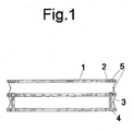
Figure 1 .- It shows a main detailed elevation view of 'Improved system of foldable grilles for windows and doors' wherein the three lower bars with their connectors and open hinge-type joint can be seen. -
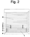
Figure 2 .- It shows a main elevation view of 'Improved system of foldable grilles for windows and doors' in closed-shutter position. -
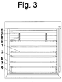
Figure 3 .- It shows a main elevation view of 'Improved system of foldable grilles for windows and doors' in open-shutter and protected-opening position. -
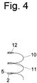
Figure 4 .- It shows a main sectional detailed view of the 'Improved system of foldable grilles for windows and doors' mounted with insect screen. - In the cited figures the following constituent elements can be highlighted;
- 1. Bars.
- 2. Connectors.
- 3. Hinge-type joint between successive bars by means of two profiles for each of the ends of each two bars to be joined, joined in a common axis of rotation that moves from an internal bar folding position, to another stop end position in the proximity of the guide of the shutter itself in which the maximum distance between bars or unfolding position is obtained.
- 4. Guide profile fixed to the lower bar.
- 5. Clamp that moves vertically around the guide profile.
- 6. Conventional shutter
- 7. Vertical profile joined together to the upper bar provided with central slot and saw-tooth outer face.
- 8. Lock plate with saw-tooth internal face.
- 9. Shutter stop.
- 10. Mesh with insect screen effect
- 11. Rods interspersed in the mesh at the same distance as the bars.
- 12. Guide fixed to the vertical surface of each bar.
- In the light of the
figures 1-3 , it can be seen by way of example of preferred embodiment, how the 'Improved system of foldable grilles for windows and doors' can be installed based on the use ofbars 1 manufactured by way of example in aluminium provided with the correspondingstandardized connectors 2, also made by way of example in polyethylene and, likewise, profiles of hingedjoints 3 made of stainless steel designed for mounting in the opening of a window provided with aconventional shutter 6 and two-leaf sliding window which further incorporates a system to prevent jamming of the assembly in its opening or closing movement by making use of corresponding guide profiles fixed to thelower bar 4 and corresponding clamps that move vertically around theguide profile 5 for each of the bars above the lowest bar. - To that end, the aforementioned
horizontal bars 1 provided with the correspondingconnectors 2 have been arranged to form a width similar to that of theshutter 6 itself, designed to be introduced next to the shutter and between the guides thereof, joined at their ends successively by hinge-type joints (3) with folding inward the window, forming a complete folding position on itself as shown inFigure 2 when theshutter 6 is completely closed, to a maximum open position as shown inFigure 3 in which the protection function for which it has been conceived is appreciated. - Following the introduction of the assembly between the guides, it is fixed to the lower end of the
shutter 6 making use of corresponding vertical profiles 7 integral to the upper bar and provided with a central slot to adapt to the height of the stop 9 and saw-tooth outer face which, in combination with the corresponding locking plate 8 with a saw-tooth internal face are completely blocked once the two existing screws in corresponding stops 9 of the shutter are tightened. Obviously, it is possible to design the connection betweenbars 1 provided withconnectors 2 by means ofhinge mechanisms 3 and fixing on the end ofsuccessive bars 1 adapting the length of thebar 1 to the required width, although alternatively, it is also possible to design each bar in two profiles provided with telescopic adjustment that adapts to the required width, or play with intermediate supplements to theconnectors 2 that provide some adjustment of the assembly to the required measure. - Alternatively, if required by the application, the
successive bars 1 can accommodate amesh 10 provided with the correspondingrods 11 designed for manual insertion inside theguides 12 existing on the exposed side of each bar in order to cover the existing gaps between the bars once deployed, as an insect screen. - As an alternative embodiment, instead of an installation on a window opening provided with a shutter, the application of the invention is evident by integrating it in the manufacture of the shutter itself as a single assembly incorporating the described system.
- It is not considered necessary to make the present specification more extensive so that any person skilled in the art understands the scope of the invention and the advantages derived from its use.
- The materials chosen for the manufacture of the different elements described, other systems for connection between the aforementioned connectors such as belts or chains, the use of locking systems of the shutter belt so that it is not used by children or additional latches not described herein for fixing the assembly from the inside, the arrangement, shapes and sizes or even the techniques used for its manufacture, will be susceptible to modification as long as it does not involve an alteration to the essence of the invention.
- The terms in which this specification has been written should always be taken in a broad and non-limiting sense.
Claims (4)
- System of foldable grilles for windows and doors for integration into a window or door opening provided with shutter, characterised in that it is composed of the following elements:a) A set of bars, each provided with corresponding standardised connectors in each of its ends designed to slide inside the shutter guides.b) Attaching system between the said connectors located at the ends of successive bars, which make possible a vertical movement of each bar inside the guides from a position of overlapping bars to a position in which the said bars are separated at a maximum distance.c) System for fixing the lower bar to the existing window opening in its base or lowest side.d) System for fixing the upper bar to the lower end of the shutter, making integral the vertical movement of the upper bar and that of the lower slat of the shutter.
- Improved system of foldable grilles for windows and doors according to claim 1, characterised in that, alternatively, in order to ensure the fixation of the assembly following the shutter taking advantage of the two stops of the shutter itself arranged at a variable height, the upper bar of the assembly incorporates corresponding complementary vertical profiles fixed at its lower end to said bar, provided with a central adjustment slot at the height of the stop of the shutter and mooring and locking system on said stop.
- Improved system of foldable grilles for windows and doors according to claim 1 and 2, characterised in that, alternatively the described system is complemented by the provision of corresponding vertical profiles fixed to the lowest bar as a guide through which all the upper bars have to move in the opening or closing movement of the shutter, by incorporating each bar that is above a clamp for each of the two guides, which moves vertically around the guide and prevents the bars from becoming uneven.
- Improved system of foldable grilles for windows and doors according to claim 1, 2 and 3, characterised in that, alternatively, it can accommodate a mesh provided with rods interspersed at equal distance to the bars designed for fixing by a simple clip for inserting each one of the aforementioned rods inside existing guides in each successive baluster enabled for this purpose, until it is fully integrated into the existing gaps between the bars once deployed.
Applications Claiming Priority (2)
| Application Number | Priority Date | Filing Date | Title |
|---|---|---|---|
| ES201631288U ES1171133Y (en) | 2016-10-27 | 2016-10-27 | System of folding bars for windows and doors improved |
| PCT/ES2017/070716 WO2018078206A1 (en) | 2016-10-27 | 2017-10-25 | Improved system of foldable grilles for windows and doors |
Publications (3)
| Publication Number | Publication Date |
|---|---|
| EP3533965A1 true EP3533965A1 (en) | 2019-09-04 |
| EP3533965A4 EP3533965A4 (en) | 2020-07-01 |
| EP3533965B1 EP3533965B1 (en) | 2022-02-23 |
Family
ID=57358702
Family Applications (1)
| Application Number | Title | Priority Date | Filing Date |
|---|---|---|---|
| EP17866258.1A Not-in-force EP3533965B1 (en) | 2016-10-27 | 2017-10-25 | Foldable grille for windows and doors |
Country Status (4)
| Country | Link |
|---|---|
| EP (1) | EP3533965B1 (en) |
| CN (1) | CN210858520U (en) |
| ES (1) | ES1171133Y (en) |
| WO (1) | WO2018078206A1 (en) |
Families Citing this family (2)
| Publication number | Priority date | Publication date | Assignee | Title |
|---|---|---|---|---|
| CN112536575B (en) * | 2020-12-03 | 2022-07-12 | 江西朝阳机械有限公司 | Manufacturing process of ventilation grid for escape fire door |
| CN113819536A (en) * | 2021-09-29 | 2021-12-21 | 朱照林 | Horizontal shutter |
Family Cites Families (9)
| Publication number | Priority date | Publication date | Assignee | Title |
|---|---|---|---|---|
| US1612771A (en) * | 1923-08-16 | 1926-12-28 | Pfeiffer Oswald | Collapsible grid |
| US1790880A (en) * | 1929-06-14 | 1931-02-03 | Soo Frank | Safety window |
| US1908919A (en) * | 1932-07-11 | 1933-05-16 | Lewis H Reed | Safety device for windows |
| FR1030176A (en) * | 1950-01-03 | 1953-06-10 | Improvements to double-acting roller shutters | |
| FR1314328A (en) | 1962-02-09 | 1963-01-04 | Security grille for windows and doors | |
| DE8714746U1 (en) * | 1987-11-05 | 1988-01-21 | Derer, Andreas, Dipl.-Ing. (FH), 7303 Neuhausen | Combined window protection |
| NL1003304C2 (en) * | 1996-06-08 | 1997-12-10 | Leen Huisman B V | Screen layout, construction profile and cloth therefor, and building such as greenhouse in which this has been applied |
| DE19825445A1 (en) * | 1998-06-06 | 1999-12-09 | Klaus Specker | Insect, sight and sun protection of fabric for window and door apertures |
| EP3023572A1 (en) * | 2014-11-21 | 2016-05-25 | Ivan Dorado Garrido | A folding grille system for windows and doors |
-
2016
- 2016-10-27 ES ES201631288U patent/ES1171133Y/en not_active Expired - Fee Related
-
2017
- 2017-10-25 WO PCT/ES2017/070716 patent/WO2018078206A1/en not_active Ceased
- 2017-10-25 CN CN201790001395.4U patent/CN210858520U/en not_active Expired - Fee Related
- 2017-10-25 EP EP17866258.1A patent/EP3533965B1/en not_active Not-in-force
Also Published As
| Publication number | Publication date |
|---|---|
| WO2018078206A1 (en) | 2018-05-03 |
| EP3533965A4 (en) | 2020-07-01 |
| EP3533965B1 (en) | 2022-02-23 |
| CN210858520U (en) | 2020-06-26 |
| ES1171133U (en) | 2016-11-29 |
| ES1171133Y (en) | 2017-02-20 |
Similar Documents
| Publication | Publication Date | Title |
|---|---|---|
| US5657578A (en) | Easy out fire escape window gate | |
| CA2988015A1 (en) | Expanding window covering | |
| CA2911872A1 (en) | Around-the-corner multi-point lock mechanism for casement and awning windows | |
| EP3533965B1 (en) | Foldable grille for windows and doors | |
| EP3540172B1 (en) | Facing shell assembly for an insulating glass unit and insulating glass unit with such an assembly | |
| US4400912A (en) | Patio door and window guard system | |
| US10801259B1 (en) | Flexible hurricane window panel installable from inside a building | |
| KR100824370B1 (en) | Multi-stage pinch prevention mechanism for door | |
| US20090277092A1 (en) | Telescoping security window | |
| EP2725180B1 (en) | Mounting accessory | |
| DE3239415A1 (en) | Lazy-tongs type grille | |
| US20180245384A1 (en) | Double throw window lock | |
| EP2716857B1 (en) | Adjustable mounting arrangement for a window screening | |
| EP3133229A1 (en) | Window or door locking system | |
| CA2971602C (en) | Shutter slat | |
| EP2789784B1 (en) | Building termination in explosive inhibiting design with wire rope loop fixing | |
| US20110100565A1 (en) | Self-locking coupling element between shutter slats | |
| EP3023572A1 (en) | A folding grille system for windows and doors | |
| EP2357311B1 (en) | Self-locking slat for shutter | |
| AU2008100724A4 (en) | Double Gate Latching Mechanism | |
| ES2258305T3 (en) | SECURITY DEVICE WITH SIMULTANEOUS SHIELDING, FOR WINDOWS, DOORS OR SIMILAR. | |
| KR20210021748A (en) | Device for prevention the wedge of clotheson door | |
| RU2344262C1 (en) | Window protection mechanism (versions) | |
| US20170234049A1 (en) | Adjustable casement window sash lifter | |
| EP3567203A1 (en) | Device for the protection of openings in buildings and constructions |
Legal Events
| Date | Code | Title | Description |
|---|---|---|---|
| STAA | Information on the status of an ep patent application or granted ep patent |
Free format text: STATUS: THE INTERNATIONAL PUBLICATION HAS BEEN MADE |
|
| PUAI | Public reference made under article 153(3) epc to a published international application that has entered the european phase |
Free format text: ORIGINAL CODE: 0009012 |
|
| STAA | Information on the status of an ep patent application or granted ep patent |
Free format text: STATUS: REQUEST FOR EXAMINATION WAS MADE |
|
| 17P | Request for examination filed |
Effective date: 20190418 |
|
| AK | Designated contracting states |
Kind code of ref document: A1 Designated state(s): AL AT BE BG CH CY CZ DE DK EE ES FI FR GB GR HR HU IE IS IT LI LT LU LV MC MK MT NL NO PL PT RO RS SE SI SK SM TR |
|
| AX | Request for extension of the european patent |
Extension state: BA ME |
|
| DAV | Request for validation of the european patent (deleted) | ||
| DAX | Request for extension of the european patent (deleted) | ||
| A4 | Supplementary search report drawn up and despatched |
Effective date: 20200529 |
|
| RIC1 | Information provided on ipc code assigned before grant |
Ipc: E06B 9/52 20060101ALN20200525BHEP Ipc: E06B 9/06 20060101AFI20200525BHEP |
|
| REG | Reference to a national code |
Ref country code: DE Ref legal event code: R079 Ref document number: 602017053845 Country of ref document: DE Free format text: PREVIOUS MAIN CLASS: E06B0009010000 Ipc: E06B0009060000 |
|
| RIC1 | Information provided on ipc code assigned before grant |
Ipc: E06B 9/52 20060101ALN20210728BHEP Ipc: E06B 9/06 20060101AFI20210728BHEP |
|
| GRAP | Despatch of communication of intention to grant a patent |
Free format text: ORIGINAL CODE: EPIDOSNIGR1 |
|
| STAA | Information on the status of an ep patent application or granted ep patent |
Free format text: STATUS: GRANT OF PATENT IS INTENDED |
|
| INTG | Intention to grant announced |
Effective date: 20210923 |
|
| GRAS | Grant fee paid |
Free format text: ORIGINAL CODE: EPIDOSNIGR3 |
|
| GRAA | (expected) grant |
Free format text: ORIGINAL CODE: 0009210 |
|
| STAA | Information on the status of an ep patent application or granted ep patent |
Free format text: STATUS: THE PATENT HAS BEEN GRANTED |
|
| AK | Designated contracting states |
Kind code of ref document: B1 Designated state(s): AL AT BE BG CH CY CZ DE DK EE ES FI FR GB GR HR HU IE IS IT LI LT LU LV MC MK MT NL NO PL PT RO RS SE SI SK SM TR |
|
| REG | Reference to a national code |
Ref country code: GB Ref legal event code: FG4D |
|
| REG | Reference to a national code |
Ref country code: CH Ref legal event code: EP |
|
| REG | Reference to a national code |
Ref country code: AT Ref legal event code: REF Ref document number: 1470598 Country of ref document: AT Kind code of ref document: T Effective date: 20220315 |
|
| REG | Reference to a national code |
Ref country code: IE Ref legal event code: FG4D |
|
| REG | Reference to a national code |
Ref country code: DE Ref legal event code: R096 Ref document number: 602017053845 Country of ref document: DE |
|
| REG | Reference to a national code |
Ref country code: LT Ref legal event code: MG9D |
|
| REG | Reference to a national code |
Ref country code: NL Ref legal event code: MP Effective date: 20220223 |
|
| REG | Reference to a national code |
Ref country code: AT Ref legal event code: MK05 Ref document number: 1470598 Country of ref document: AT Kind code of ref document: T Effective date: 20220223 |
|
| PG25 | Lapsed in a contracting state [announced via postgrant information from national office to epo] |
Ref country code: SE Free format text: LAPSE BECAUSE OF FAILURE TO SUBMIT A TRANSLATION OF THE DESCRIPTION OR TO PAY THE FEE WITHIN THE PRESCRIBED TIME-LIMIT Effective date: 20220223 Ref country code: RS Free format text: LAPSE BECAUSE OF FAILURE TO SUBMIT A TRANSLATION OF THE DESCRIPTION OR TO PAY THE FEE WITHIN THE PRESCRIBED TIME-LIMIT Effective date: 20220223 Ref country code: PT Free format text: LAPSE BECAUSE OF FAILURE TO SUBMIT A TRANSLATION OF THE DESCRIPTION OR TO PAY THE FEE WITHIN THE PRESCRIBED TIME-LIMIT Effective date: 20220623 Ref country code: NO Free format text: LAPSE BECAUSE OF FAILURE TO SUBMIT A TRANSLATION OF THE DESCRIPTION OR TO PAY THE FEE WITHIN THE PRESCRIBED TIME-LIMIT Effective date: 20220523 Ref country code: NL Free format text: LAPSE BECAUSE OF FAILURE TO SUBMIT A TRANSLATION OF THE DESCRIPTION OR TO PAY THE FEE WITHIN THE PRESCRIBED TIME-LIMIT Effective date: 20220223 Ref country code: LT Free format text: LAPSE BECAUSE OF FAILURE TO SUBMIT A TRANSLATION OF THE DESCRIPTION OR TO PAY THE FEE WITHIN THE PRESCRIBED TIME-LIMIT Effective date: 20220223 Ref country code: HR Free format text: LAPSE BECAUSE OF FAILURE TO SUBMIT A TRANSLATION OF THE DESCRIPTION OR TO PAY THE FEE WITHIN THE PRESCRIBED TIME-LIMIT Effective date: 20220223 Ref country code: ES Free format text: LAPSE BECAUSE OF FAILURE TO SUBMIT A TRANSLATION OF THE DESCRIPTION OR TO PAY THE FEE WITHIN THE PRESCRIBED TIME-LIMIT Effective date: 20220223 Ref country code: BG Free format text: LAPSE BECAUSE OF FAILURE TO SUBMIT A TRANSLATION OF THE DESCRIPTION OR TO PAY THE FEE WITHIN THE PRESCRIBED TIME-LIMIT Effective date: 20220523 |
|
| PG25 | Lapsed in a contracting state [announced via postgrant information from national office to epo] |
Ref country code: PL Free format text: LAPSE BECAUSE OF FAILURE TO SUBMIT A TRANSLATION OF THE DESCRIPTION OR TO PAY THE FEE WITHIN THE PRESCRIBED TIME-LIMIT Effective date: 20220223 Ref country code: LV Free format text: LAPSE BECAUSE OF FAILURE TO SUBMIT A TRANSLATION OF THE DESCRIPTION OR TO PAY THE FEE WITHIN THE PRESCRIBED TIME-LIMIT Effective date: 20220223 Ref country code: GR Free format text: LAPSE BECAUSE OF FAILURE TO SUBMIT A TRANSLATION OF THE DESCRIPTION OR TO PAY THE FEE WITHIN THE PRESCRIBED TIME-LIMIT Effective date: 20220524 Ref country code: FI Free format text: LAPSE BECAUSE OF FAILURE TO SUBMIT A TRANSLATION OF THE DESCRIPTION OR TO PAY THE FEE WITHIN THE PRESCRIBED TIME-LIMIT Effective date: 20220223 Ref country code: AT Free format text: LAPSE BECAUSE OF FAILURE TO SUBMIT A TRANSLATION OF THE DESCRIPTION OR TO PAY THE FEE WITHIN THE PRESCRIBED TIME-LIMIT Effective date: 20220223 |
|
| PG25 | Lapsed in a contracting state [announced via postgrant information from national office to epo] |
Ref country code: IS Free format text: LAPSE BECAUSE OF FAILURE TO SUBMIT A TRANSLATION OF THE DESCRIPTION OR TO PAY THE FEE WITHIN THE PRESCRIBED TIME-LIMIT Effective date: 20220623 |
|
| PG25 | Lapsed in a contracting state [announced via postgrant information from national office to epo] |
Ref country code: SK Free format text: LAPSE BECAUSE OF FAILURE TO SUBMIT A TRANSLATION OF THE DESCRIPTION OR TO PAY THE FEE WITHIN THE PRESCRIBED TIME-LIMIT Effective date: 20220223 Ref country code: RO Free format text: LAPSE BECAUSE OF FAILURE TO SUBMIT A TRANSLATION OF THE DESCRIPTION OR TO PAY THE FEE WITHIN THE PRESCRIBED TIME-LIMIT Effective date: 20220223 Ref country code: EE Free format text: LAPSE BECAUSE OF FAILURE TO SUBMIT A TRANSLATION OF THE DESCRIPTION OR TO PAY THE FEE WITHIN THE PRESCRIBED TIME-LIMIT Effective date: 20220223 Ref country code: DK Free format text: LAPSE BECAUSE OF FAILURE TO SUBMIT A TRANSLATION OF THE DESCRIPTION OR TO PAY THE FEE WITHIN THE PRESCRIBED TIME-LIMIT Effective date: 20220223 Ref country code: CZ Free format text: LAPSE BECAUSE OF FAILURE TO SUBMIT A TRANSLATION OF THE DESCRIPTION OR TO PAY THE FEE WITHIN THE PRESCRIBED TIME-LIMIT Effective date: 20220223 Ref country code: SM Free format text: LAPSE BECAUSE OF FAILURE TO SUBMIT A TRANSLATION OF THE DESCRIPTION OR TO PAY THE FEE WITHIN THE PRESCRIBED TIME-LIMIT Effective date: 20220223 |
|
| REG | Reference to a national code |
Ref country code: DE Ref legal event code: R097 Ref document number: 602017053845 Country of ref document: DE |
|
| PG25 | Lapsed in a contracting state [announced via postgrant information from national office to epo] |
Ref country code: AL Free format text: LAPSE BECAUSE OF FAILURE TO SUBMIT A TRANSLATION OF THE DESCRIPTION OR TO PAY THE FEE WITHIN THE PRESCRIBED TIME-LIMIT Effective date: 20220223 |
|
| PLBE | No opposition filed within time limit |
Free format text: ORIGINAL CODE: 0009261 |
|
| STAA | Information on the status of an ep patent application or granted ep patent |
Free format text: STATUS: NO OPPOSITION FILED WITHIN TIME LIMIT |
|
| 26N | No opposition filed |
Effective date: 20221124 |
|
| PG25 | Lapsed in a contracting state [announced via postgrant information from national office to epo] |
Ref country code: SI Free format text: LAPSE BECAUSE OF FAILURE TO SUBMIT A TRANSLATION OF THE DESCRIPTION OR TO PAY THE FEE WITHIN THE PRESCRIBED TIME-LIMIT Effective date: 20220223 |
|
| REG | Reference to a national code |
Ref country code: DE Ref legal event code: R119 Ref document number: 602017053845 Country of ref document: DE |
|
| PG25 | Lapsed in a contracting state [announced via postgrant information from national office to epo] |
Ref country code: MC Free format text: LAPSE BECAUSE OF FAILURE TO SUBMIT A TRANSLATION OF THE DESCRIPTION OR TO PAY THE FEE WITHIN THE PRESCRIBED TIME-LIMIT Effective date: 20220223 |
|
| REG | Reference to a national code |
Ref country code: CH Ref legal event code: PL |
|
| REG | Reference to a national code |
Ref country code: BE Ref legal event code: MM Effective date: 20221031 |
|
| GBPC | Gb: european patent ceased through non-payment of renewal fee |
Effective date: 20221025 |
|
| PG25 | Lapsed in a contracting state [announced via postgrant information from national office to epo] |
Ref country code: LU Free format text: LAPSE BECAUSE OF NON-PAYMENT OF DUE FEES Effective date: 20221025 |
|
| PG25 | Lapsed in a contracting state [announced via postgrant information from national office to epo] |
Ref country code: LI Free format text: LAPSE BECAUSE OF NON-PAYMENT OF DUE FEES Effective date: 20221031 Ref country code: IT Free format text: LAPSE BECAUSE OF FAILURE TO SUBMIT A TRANSLATION OF THE DESCRIPTION OR TO PAY THE FEE WITHIN THE PRESCRIBED TIME-LIMIT Effective date: 20220223 Ref country code: FR Free format text: LAPSE BECAUSE OF NON-PAYMENT OF DUE FEES Effective date: 20221031 Ref country code: DE Free format text: LAPSE BECAUSE OF NON-PAYMENT OF DUE FEES Effective date: 20230503 Ref country code: CH Free format text: LAPSE BECAUSE OF NON-PAYMENT OF DUE FEES Effective date: 20221031 |
|
| PG25 | Lapsed in a contracting state [announced via postgrant information from national office to epo] |
Ref country code: BE Free format text: LAPSE BECAUSE OF NON-PAYMENT OF DUE FEES Effective date: 20221031 |
|
| PG25 | Lapsed in a contracting state [announced via postgrant information from national office to epo] |
Ref country code: IE Free format text: LAPSE BECAUSE OF NON-PAYMENT OF DUE FEES Effective date: 20221025 Ref country code: GB Free format text: LAPSE BECAUSE OF NON-PAYMENT OF DUE FEES Effective date: 20221025 |
|
| PG25 | Lapsed in a contracting state [announced via postgrant information from national office to epo] |
Ref country code: HU Free format text: LAPSE BECAUSE OF FAILURE TO SUBMIT A TRANSLATION OF THE DESCRIPTION OR TO PAY THE FEE WITHIN THE PRESCRIBED TIME-LIMIT; INVALID AB INITIO Effective date: 20171025 |
|
| PG25 | Lapsed in a contracting state [announced via postgrant information from national office to epo] |
Ref country code: CY Free format text: LAPSE BECAUSE OF FAILURE TO SUBMIT A TRANSLATION OF THE DESCRIPTION OR TO PAY THE FEE WITHIN THE PRESCRIBED TIME-LIMIT Effective date: 20220223 |
|
| PG25 | Lapsed in a contracting state [announced via postgrant information from national office to epo] |
Ref country code: MK Free format text: LAPSE BECAUSE OF FAILURE TO SUBMIT A TRANSLATION OF THE DESCRIPTION OR TO PAY THE FEE WITHIN THE PRESCRIBED TIME-LIMIT Effective date: 20220223 |
|
| PG25 | Lapsed in a contracting state [announced via postgrant information from national office to epo] |
Ref country code: TR Free format text: LAPSE BECAUSE OF FAILURE TO SUBMIT A TRANSLATION OF THE DESCRIPTION OR TO PAY THE FEE WITHIN THE PRESCRIBED TIME-LIMIT Effective date: 20220223 |
|
| PG25 | Lapsed in a contracting state [announced via postgrant information from national office to epo] |
Ref country code: MT Free format text: LAPSE BECAUSE OF FAILURE TO SUBMIT A TRANSLATION OF THE DESCRIPTION OR TO PAY THE FEE WITHIN THE PRESCRIBED TIME-LIMIT Effective date: 20220223 |