EP3533816A1 - Preformed protective cover and wind turbine blade - Google Patents
Preformed protective cover and wind turbine blade Download PDFInfo
- Publication number
- EP3533816A1 EP3533816A1 EP19164579.5A EP19164579A EP3533816A1 EP 3533816 A1 EP3533816 A1 EP 3533816A1 EP 19164579 A EP19164579 A EP 19164579A EP 3533816 A1 EP3533816 A1 EP 3533816A1
- Authority
- EP
- European Patent Office
- Prior art keywords
- protective cover
- preformed protective
- wind turbine
- turbine blade
- preformed
- Prior art date
- Legal status (The legal status is an assumption and is not a legal conclusion. Google has not performed a legal analysis and makes no representation as to the accuracy of the status listed.)
- Pending
Links
- 230000001681 protective effect Effects 0.000 title claims abstract description 117
- 239000000463 material Substances 0.000 claims abstract description 42
- 239000004814 polyurethane Substances 0.000 claims abstract description 42
- 229920002635 polyurethane Polymers 0.000 claims abstract description 42
- 239000012948 isocyanate Substances 0.000 claims abstract description 26
- 150000002513 isocyanates Chemical class 0.000 claims abstract description 26
- 230000002093 peripheral effect Effects 0.000 claims abstract description 24
- CDQSJQSWAWPGKG-UHFFFAOYSA-N butane-1,1-diol Chemical compound CCCC(O)O CDQSJQSWAWPGKG-UHFFFAOYSA-N 0.000 claims abstract description 23
- 229920005862 polyol Polymers 0.000 claims abstract description 23
- 150000003077 polyols Chemical class 0.000 claims abstract description 23
- WERYXYBDKMZEQL-UHFFFAOYSA-N butane-1,4-diol Chemical compound OCCCCO WERYXYBDKMZEQL-UHFFFAOYSA-N 0.000 claims description 10
- 239000000049 pigment Substances 0.000 claims description 6
- 230000003247 decreasing effect Effects 0.000 claims description 5
- UPMLOUAZCHDJJD-UHFFFAOYSA-N 4,4'-Diphenylmethane Diisocyanate Chemical class C1=CC(N=C=O)=CC=C1CC1=CC=C(N=C=O)C=C1 UPMLOUAZCHDJJD-UHFFFAOYSA-N 0.000 claims description 3
- 230000003628 erosive effect Effects 0.000 description 35
- 238000000034 method Methods 0.000 description 26
- 239000000853 adhesive Substances 0.000 description 16
- 230000001070 adhesive effect Effects 0.000 description 16
- 239000010410 layer Substances 0.000 description 12
- 238000005496 tempering Methods 0.000 description 10
- 238000010438 heat treatment Methods 0.000 description 9
- 239000002184 metal Substances 0.000 description 8
- 239000000203 mixture Substances 0.000 description 8
- 239000007787 solid Substances 0.000 description 8
- 238000007872 degassing Methods 0.000 description 6
- 230000010354 integration Effects 0.000 description 6
- 238000002156 mixing Methods 0.000 description 6
- 238000004519 manufacturing process Methods 0.000 description 5
- 230000007613 environmental effect Effects 0.000 description 4
- 239000002861 polymer material Substances 0.000 description 4
- 238000011417 postcuring Methods 0.000 description 4
- 239000002131 composite material Substances 0.000 description 3
- 238000000465 moulding Methods 0.000 description 3
- 238000003825 pressing Methods 0.000 description 3
- 238000005086 pumping Methods 0.000 description 3
- 230000007704 transition Effects 0.000 description 3
- GNFTZDOKVXKIBK-UHFFFAOYSA-N 3-(2-methoxyethoxy)benzohydrazide Chemical compound COCCOC1=CC=CC(C(=O)NN)=C1 GNFTZDOKVXKIBK-UHFFFAOYSA-N 0.000 description 2
- 238000000227 grinding Methods 0.000 description 2
- 238000003801 milling Methods 0.000 description 2
- 239000000758 substrate Substances 0.000 description 2
- OKTJSMMVPCPJKN-UHFFFAOYSA-N Carbon Chemical compound [C] OKTJSMMVPCPJKN-UHFFFAOYSA-N 0.000 description 1
- 239000004721 Polyphenylene oxide Substances 0.000 description 1
- 206010042255 Struck by lightning Diseases 0.000 description 1
- 241000341910 Vesta Species 0.000 description 1
- 230000015572 biosynthetic process Effects 0.000 description 1
- 229910052799 carbon Inorganic materials 0.000 description 1
- 230000000052 comparative effect Effects 0.000 description 1
- 238000005516 engineering process Methods 0.000 description 1
- 238000012423 maintenance Methods 0.000 description 1
- 238000002844 melting Methods 0.000 description 1
- 230000008018 melting Effects 0.000 description 1
- 239000003973 paint Substances 0.000 description 1
- 229920000570 polyether Polymers 0.000 description 1
- 239000011527 polyurethane coating Substances 0.000 description 1
- 239000011241 protective layer Substances 0.000 description 1
- 230000005855 radiation Effects 0.000 description 1
- 239000003566 sealing material Substances 0.000 description 1
- 239000000126 substance Substances 0.000 description 1
Images


Classifications
-
- C—CHEMISTRY; METALLURGY
- C08—ORGANIC MACROMOLECULAR COMPOUNDS; THEIR PREPARATION OR CHEMICAL WORKING-UP; COMPOSITIONS BASED THEREON
- C08G—MACROMOLECULAR COMPOUNDS OBTAINED OTHERWISE THAN BY REACTIONS ONLY INVOLVING UNSATURATED CARBON-TO-CARBON BONDS
- C08G18/00—Polymeric products of isocyanates or isothiocyanates
- C08G18/06—Polymeric products of isocyanates or isothiocyanates with compounds having active hydrogen
- C08G18/28—Polymeric products of isocyanates or isothiocyanates with compounds having active hydrogen characterised by the compounds used containing active hydrogen
- C08G18/65—Low-molecular-weight compounds having active hydrogen with high-molecular-weight compounds having active hydrogen
- C08G18/6505—Low-molecular-weight compounds having active hydrogen with high-molecular-weight compounds having active hydrogen the low-molecular compounds being compounds of group C08G18/32 or polyamines of C08G18/38
- C08G18/6511—Low-molecular-weight compounds having active hydrogen with high-molecular-weight compounds having active hydrogen the low-molecular compounds being compounds of group C08G18/32 or polyamines of C08G18/38 compounds of group C08G18/3203
-
- C—CHEMISTRY; METALLURGY
- C08—ORGANIC MACROMOLECULAR COMPOUNDS; THEIR PREPARATION OR CHEMICAL WORKING-UP; COMPOSITIONS BASED THEREON
- C08G—MACROMOLECULAR COMPOUNDS OBTAINED OTHERWISE THAN BY REACTIONS ONLY INVOLVING UNSATURATED CARBON-TO-CARBON BONDS
- C08G18/00—Polymeric products of isocyanates or isothiocyanates
- C08G18/06—Polymeric products of isocyanates or isothiocyanates with compounds having active hydrogen
- C08G18/28—Polymeric products of isocyanates or isothiocyanates with compounds having active hydrogen characterised by the compounds used containing active hydrogen
- C08G18/30—Low-molecular-weight compounds
- C08G18/32—Polyhydroxy compounds; Polyamines; Hydroxyamines
- C08G18/3203—Polyhydroxy compounds
- C08G18/3206—Polyhydroxy compounds aliphatic
-
- C—CHEMISTRY; METALLURGY
- C08—ORGANIC MACROMOLECULAR COMPOUNDS; THEIR PREPARATION OR CHEMICAL WORKING-UP; COMPOSITIONS BASED THEREON
- C08G—MACROMOLECULAR COMPOUNDS OBTAINED OTHERWISE THAN BY REACTIONS ONLY INVOLVING UNSATURATED CARBON-TO-CARBON BONDS
- C08G18/00—Polymeric products of isocyanates or isothiocyanates
- C08G18/06—Polymeric products of isocyanates or isothiocyanates with compounds having active hydrogen
- C08G18/70—Polymeric products of isocyanates or isothiocyanates with compounds having active hydrogen characterised by the isocyanates or isothiocyanates used
- C08G18/72—Polyisocyanates or polyisothiocyanates
- C08G18/74—Polyisocyanates or polyisothiocyanates cyclic
- C08G18/76—Polyisocyanates or polyisothiocyanates cyclic aromatic
- C08G18/7657—Polyisocyanates or polyisothiocyanates cyclic aromatic containing two or more aromatic rings
- C08G18/7664—Polyisocyanates or polyisothiocyanates cyclic aromatic containing two or more aromatic rings containing alkylene polyphenyl groups
- C08G18/7671—Polyisocyanates or polyisothiocyanates cyclic aromatic containing two or more aromatic rings containing alkylene polyphenyl groups containing only one alkylene bisphenyl group
-
- C—CHEMISTRY; METALLURGY
- C08—ORGANIC MACROMOLECULAR COMPOUNDS; THEIR PREPARATION OR CHEMICAL WORKING-UP; COMPOSITIONS BASED THEREON
- C08J—WORKING-UP; GENERAL PROCESSES OF COMPOUNDING; AFTER-TREATMENT NOT COVERED BY SUBCLASSES C08B, C08C, C08F, C08G or C08H
- C08J5/00—Manufacture of articles or shaped materials containing macromolecular substances
- C08J5/12—Bonding of a preformed macromolecular material to the same or other solid material such as metal, glass, leather, e.g. using adhesives
- C08J5/124—Bonding of a preformed macromolecular material to the same or other solid material such as metal, glass, leather, e.g. using adhesives using adhesives based on a macromolecular component
-
- C—CHEMISTRY; METALLURGY
- C08—ORGANIC MACROMOLECULAR COMPOUNDS; THEIR PREPARATION OR CHEMICAL WORKING-UP; COMPOSITIONS BASED THEREON
- C08L—COMPOSITIONS OF MACROMOLECULAR COMPOUNDS
- C08L75/00—Compositions of polyureas or polyurethanes; Compositions of derivatives of such polymers
- C08L75/04—Polyurethanes
-
- F—MECHANICAL ENGINEERING; LIGHTING; HEATING; WEAPONS; BLASTING
- F03—MACHINES OR ENGINES FOR LIQUIDS; WIND, SPRING, OR WEIGHT MOTORS; PRODUCING MECHANICAL POWER OR A REACTIVE PROPULSIVE THRUST, NOT OTHERWISE PROVIDED FOR
- F03D—WIND MOTORS
- F03D1/00—Wind motors with rotation axis substantially parallel to the air flow entering the rotor
- F03D1/06—Rotors
- F03D1/065—Rotors characterised by their construction elements
- F03D1/0675—Rotors characterised by their construction elements of the blades
-
- B—PERFORMING OPERATIONS; TRANSPORTING
- B29—WORKING OF PLASTICS; WORKING OF SUBSTANCES IN A PLASTIC STATE IN GENERAL
- B29D—PRODUCING PARTICULAR ARTICLES FROM PLASTICS OR FROM SUBSTANCES IN A PLASTIC STATE
- B29D99/00—Subject matter not provided for in other groups of this subclass
- B29D99/0025—Producing blades or the like, e.g. blades for turbines, propellers, or wings
-
- B—PERFORMING OPERATIONS; TRANSPORTING
- B29—WORKING OF PLASTICS; WORKING OF SUBSTANCES IN A PLASTIC STATE IN GENERAL
- B29K—INDEXING SCHEME ASSOCIATED WITH SUBCLASSES B29B, B29C OR B29D, RELATING TO MOULDING MATERIALS OR TO MATERIALS FOR MOULDS, REINFORCEMENTS, FILLERS OR PREFORMED PARTS, e.g. INSERTS
- B29K2075/00—Use of PU, i.e. polyureas or polyurethanes or derivatives thereof, as moulding material
-
- C—CHEMISTRY; METALLURGY
- C08—ORGANIC MACROMOLECULAR COMPOUNDS; THEIR PREPARATION OR CHEMICAL WORKING-UP; COMPOSITIONS BASED THEREON
- C08J—WORKING-UP; GENERAL PROCESSES OF COMPOUNDING; AFTER-TREATMENT NOT COVERED BY SUBCLASSES C08B, C08C, C08F, C08G or C08H
- C08J2375/00—Characterised by the use of polyureas or polyurethanes; Derivatives of such polymers
- C08J2375/04—Polyurethanes
-
- C—CHEMISTRY; METALLURGY
- C08—ORGANIC MACROMOLECULAR COMPOUNDS; THEIR PREPARATION OR CHEMICAL WORKING-UP; COMPOSITIONS BASED THEREON
- C08J—WORKING-UP; GENERAL PROCESSES OF COMPOUNDING; AFTER-TREATMENT NOT COVERED BY SUBCLASSES C08B, C08C, C08F, C08G or C08H
- C08J2475/00—Characterised by the use of polyureas or polyurethanes; Derivatives of such polymers
- C08J2475/04—Polyurethanes
-
- F—MECHANICAL ENGINEERING; LIGHTING; HEATING; WEAPONS; BLASTING
- F03—MACHINES OR ENGINES FOR LIQUIDS; WIND, SPRING, OR WEIGHT MOTORS; PRODUCING MECHANICAL POWER OR A REACTIVE PROPULSIVE THRUST, NOT OTHERWISE PROVIDED FOR
- F03D—WIND MOTORS
- F03D80/00—Details, components or accessories not provided for in groups F03D1/00 - F03D17/00
- F03D80/30—Lightning protection
-
- F—MECHANICAL ENGINEERING; LIGHTING; HEATING; WEAPONS; BLASTING
- F03—MACHINES OR ENGINES FOR LIQUIDS; WIND, SPRING, OR WEIGHT MOTORS; PRODUCING MECHANICAL POWER OR A REACTIVE PROPULSIVE THRUST, NOT OTHERWISE PROVIDED FOR
- F03D—WIND MOTORS
- F03D80/00—Details, components or accessories not provided for in groups F03D1/00 - F03D17/00
- F03D80/40—Ice detection; De-icing means
-
- F—MECHANICAL ENGINEERING; LIGHTING; HEATING; WEAPONS; BLASTING
- F05—INDEXING SCHEMES RELATING TO ENGINES OR PUMPS IN VARIOUS SUBCLASSES OF CLASSES F01-F04
- F05B—INDEXING SCHEME RELATING TO WIND, SPRING, WEIGHT, INERTIA OR LIKE MOTORS, TO MACHINES OR ENGINES FOR LIQUIDS COVERED BY SUBCLASSES F03B, F03D AND F03G
- F05B2230/00—Manufacture
- F05B2230/20—Manufacture essentially without removing material
- F05B2230/23—Manufacture essentially without removing material by permanently joining parts together
-
- F—MECHANICAL ENGINEERING; LIGHTING; HEATING; WEAPONS; BLASTING
- F05—INDEXING SCHEMES RELATING TO ENGINES OR PUMPS IN VARIOUS SUBCLASSES OF CLASSES F01-F04
- F05B—INDEXING SCHEME RELATING TO WIND, SPRING, WEIGHT, INERTIA OR LIKE MOTORS, TO MACHINES OR ENGINES FOR LIQUIDS COVERED BY SUBCLASSES F03B, F03D AND F03G
- F05B2230/00—Manufacture
- F05B2230/40—Heat treatment
-
- F—MECHANICAL ENGINEERING; LIGHTING; HEATING; WEAPONS; BLASTING
- F05—INDEXING SCHEMES RELATING TO ENGINES OR PUMPS IN VARIOUS SUBCLASSES OF CLASSES F01-F04
- F05B—INDEXING SCHEME RELATING TO WIND, SPRING, WEIGHT, INERTIA OR LIKE MOTORS, TO MACHINES OR ENGINES FOR LIQUIDS COVERED BY SUBCLASSES F03B, F03D AND F03G
- F05B2280/00—Materials; Properties thereof
- F05B2280/40—Organic materials
- F05B2280/4003—Synthetic polymers, e.g. plastics
-
- F—MECHANICAL ENGINEERING; LIGHTING; HEATING; WEAPONS; BLASTING
- F05—INDEXING SCHEMES RELATING TO ENGINES OR PUMPS IN VARIOUS SUBCLASSES OF CLASSES F01-F04
- F05B—INDEXING SCHEME RELATING TO WIND, SPRING, WEIGHT, INERTIA OR LIKE MOTORS, TO MACHINES OR ENGINES FOR LIQUIDS COVERED BY SUBCLASSES F03B, F03D AND F03G
- F05B2280/00—Materials; Properties thereof
- F05B2280/40—Organic materials
- F05B2280/4011—Organic materials not otherwise provided for
-
- Y—GENERAL TAGGING OF NEW TECHNOLOGICAL DEVELOPMENTS; GENERAL TAGGING OF CROSS-SECTIONAL TECHNOLOGIES SPANNING OVER SEVERAL SECTIONS OF THE IPC; TECHNICAL SUBJECTS COVERED BY FORMER USPC CROSS-REFERENCE ART COLLECTIONS [XRACs] AND DIGESTS
- Y02—TECHNOLOGIES OR APPLICATIONS FOR MITIGATION OR ADAPTATION AGAINST CLIMATE CHANGE
- Y02E—REDUCTION OF GREENHOUSE GAS [GHG] EMISSIONS, RELATED TO ENERGY GENERATION, TRANSMISSION OR DISTRIBUTION
- Y02E10/00—Energy generation through renewable energy sources
- Y02E10/70—Wind energy
- Y02E10/72—Wind turbines with rotation axis in wind direction
-
- Y—GENERAL TAGGING OF NEW TECHNOLOGICAL DEVELOPMENTS; GENERAL TAGGING OF CROSS-SECTIONAL TECHNOLOGIES SPANNING OVER SEVERAL SECTIONS OF THE IPC; TECHNICAL SUBJECTS COVERED BY FORMER USPC CROSS-REFERENCE ART COLLECTIONS [XRACs] AND DIGESTS
- Y02—TECHNOLOGIES OR APPLICATIONS FOR MITIGATION OR ADAPTATION AGAINST CLIMATE CHANGE
- Y02P—CLIMATE CHANGE MITIGATION TECHNOLOGIES IN THE PRODUCTION OR PROCESSING OF GOODS
- Y02P70/00—Climate change mitigation technologies in the production process for final industrial or consumer products
- Y02P70/50—Manufacturing or production processes characterised by the final manufactured product
Definitions
- the present invention relates to a preformed protective cover for a wind turbine blade, the preformed protective cover being made of a polyurethane material.
- the polyurethane material is characterised by being prepared from a polyol, butanediol, and an isocyanate.
- the isocyanate is an optionally modified diphenylmethane 4,4'-diisocyanate.
- the butanediol is 1,4-butanediol.
- the polyurethane material comprises an UV stabilisator and/or colour pigment(s).
- the present invention further relates to a process for preparing a polyurethane, characterised by
- the present invention further relates to a process for preparing a protective cover for a wind turbine blade, characterised by
- the tempering according to b) and/or c) is carried out at a temperature from 30°C to 50°C.
- the tempering according to b) and/or c) is carried out at a temperature about 40°C.
- the mould in step d) is preheated.
- the mould in step d) is preheated to a temperature from 90°C to 120°C.
- the mould in step d) is preheated to a temperature about 100°C.
- step e) wherein the curing in step e) is carried out at a temperature from 90°C to 120°C.
- the curing in step e) is carried out at a temperature of about 100°C.
- the curing in step e) is carried out for about 15 minutes.
- the process comprises a further step: g) post-curing.
- the post-curing in step g) takes place in about 12 hours at a temperature of about 100°C.
- the polyol, butanediol, and isocyanate are used in a ratio by weight polyol:butanediol:isocyanate of 100:(3 to 5):(30 to 35).
- the polyol, butanediol, and isocyanate are used in a ratio by weight polyol:butanediol:isocyanate of 100:4:32.3.
- the polyol comprises an UV stabilisator and/or colour pigment(s).
- the polyol in the polyurethane material or the process, is Bayflex® OS 380-A-59A.
- the isocyanate is DESMODUR® PF.
- butanediol is 1,4-butanediol.
- the present invention furthermore relates to a preformed protective cover for a wind turbine blade.
- EP 0 037 987 A2 discloses a nose cover and a rear end cover for wings, rotor blades, etc.
- WO 2004/076852 A2 (Vestas Wind Systems A/S) describes a front edge cover that is preformed to fit a wind turbine blade and subsequently adhered to the blade.
- WO 2010/122157 A1 discloses a specific chemical composition of a polyurethane coating.
- US 2013/045105 A1 discloses a turbine blade for a wind turbine includes a leading edge, a trailing edge and a recess located within the leading edge.
- the blade further includes a protective layer having an inner side and outer side, the inner side is sized and orientated to locate within the recess to facilitate withstanding impact forces applied by an object.
- One object of the present invention is to provide an improved preformed protective cover for a wind turbine blade.
- the preformed protective cover is made of a made of a polyurethane material prepared from a polyol, butanediol, and an isocyanate, the preformed protective cover is adapted to be attached along at least a part of a longitudinal edge of the wind turbine blade by adhesion of an inside of the preformed protective cover to a surface of the longitudinal edge of the wind turbine blade, the preformed protective cover is elongated in a longitudinal direction and has an at least substantially U-formed cross-section, the preformed protective cover includes a central cover section extending in the longitudinal direction and two peripheral cover sections extending in the longitudinal direction at either side of the central cover section, respectively, the central cover section has a minimum thickness of at least 1 millimetre, and each peripheral cover section has a thickness decreasing from a maximum thickness of at least 1 millimetre to a minimum thickness of less than 1/2 millimetre.
- the maximum thickness of each peripheral cover section corresponds to the minimum thickness of the central cover section.
- the minimum thickness of the central cover section is at least 2 millimetres, preferably at least 3 millimetres, more preferred at least 4 millimetres and most preferred approximately 5 millimetres.
- the thickness of the central cover section is at least substantially constant from side to side of the central cover section.
- the minimum thickness of each peripheral cover section is less than 1/3 millimetre, preferably less than 1/5 millimetres, more preferred less than 1/7 millimetres and most preferred approximately 1/10 millimetres.
- each peripheral cover section has a thickness decreasing at least substantially constantly from its maximum thickness to its minimum thickness.
- each peripheral cover section is at least 3 per cent, preferably at least 7 per cent, more preferred at least 12 per cent and most preferred at least 15 per cent of the total width of the preformed protective cover.
- the total width of the preformed protective cover is at least 30 millimetres, preferably at least 50 millimetres, more preferred at least 100 millimetres and most preferred approximately 150 to 250 millimetres.
- the total width of the preformed protective cover increases in the longitudinal direction.
- the inside of the preformed protective cover is provided with a number of protrusions having a height of between 1/2 and 2 millimetres, preferably approximately 1 millimetre.
- the preformed protective cover has a symmetry axis extending in the longitudinal direction, and wherein the inside of the preformed protective cover at either side of the symmetry axis is provided with a number of spaced elongated protrusions extending with an oblique angle in relation to the longitudinal direction.
- the invention further relates to a wind turbine blade including a preformed protective cover as described above, wherein the preformed protective cover is attached along at least a part of a longitudinal edge of the wind turbine blade by adhesion to a surface of the longitudinal edge of the wind turbine blade.
- the wind turbine blade includes a first blade shell and a second blade shell joined together to form a wind turbine blade along a first longitudinal joint at a leading edge of the wind turbine blade and along a second longitudinal joint at a trailing edge of the wind turbine blade, and wherein the preformed protective cover is attached at least approximately symmetrical about the first or second longitudinal joint, and preferably about the first longitudinal joint.
- the invention furthermore relates to a method of providing a wind turbine blade with a preformed protective cover as described above.
- the preformed protective cover is attached along at least a part of a longitudinal edge of the wind turbine blade by adhesion of the inside of the preformed protective cover to a surface of the longitudinal edge of the wind turbine blade, whereby the adhesion is performed by the following steps:
- the adhesive is provided as string of adhesive on the inside of the preformed protective cover at least substantially along a longitudinal symmetry axis of the preformed protective cover.
- the preformed protective cover is produced by the following steps:
- the wind turbine blade is provided with the preformed protective cover as a repair operation, whereby an area of said surface of the longitudinal edge of the wind turbine blade corresponding to the preformed protective cover is machined, such as by grinding or milling, before attachment of the preformed protective cover.
- the wind turbine blade is provided with the preformed protective cover when the wind turbine blade is still mounted on a wind turbine.
- the preformed protective cover as described above is made of a polymer material in the form of a polyurethane material as defined or as prepared in any one of the above embodiments.
- a wind turbine blade includes said preformed protective cover made of a polymer material in the form of a polyurethane material as defined in or as prepared in any one of the above embodiments.
- said preformed protective cover is made of a polymer material in the form of a polyurethane material as defined in or as prepared in any one of the above embodiments.
- a second invention furthermore relates to a method of making a wind turbine blade component incorporating an integrated lightning protection enhancement, leading edge protection, aerodynamic enhancement and de-ice system, the method comprises: providing the over moulding of a one piece novel polyurethane material to the blade tip region, the said material completely covering the outer surface of the blade leading edge, the said material covering the interface between the blade shell laminate and the solid metal tip lightning receptor; the integration of a novel polyurethane dielectric and aerodynamic fence at the interface between the blade shell laminate and the solid metal tip lightning receptor; further aerodynamic fences integrated at optimised positions chord-wise on the blade; integration of a novel composite heating layer to the leading edge of the blade; and integration of a lightning receptor component for the protection of the said de-ice layer.
- the novel polyurethane material is a polyurethane material as defined in or as prepared in any one of the above embodiments.
- the present invention relates to an integrated system as part of a wind turbine blade structure and associated fabrication processes for improving the resilience of wind turbine blades to all or a subset of lightning strikes, leading edge environmental erosion, aerodynamic enhancement and blade icing.
- the invention also extends to the specific composition and properties of the associated materials used in the said system in addition to the application and fabrication process.
- Wind turbines are operated in extreme environmental conditions where the wind turbine blades in particular are vulnerable to leading edge erosion, lightning strike and icing.
- a lightning strike event has the potential to cause physical damage to the turbine blade structure.
- Leading edge erosion has the possibility to cause physical damage to the leading edge of the blade.
- Blade icing causes the wind turbine to be shut down for extended periods.
- the second invention comprising: providing the over moulding of a one piece novel polyurethane material to the blade tip region; the said material completely covering the outer surface of the blade leading edge; the said material covering the interface between the blade shell laminate and the solid metal tip lightning receptor; the integration of a novel polyurethane dielectric and aerodynamic fence at the interface between the blade shell laminate and the solid metal tip lightning receptor; further aerodynamic fences integrated at optimised positions chord-wise on the blade; integration of a novel composite heating later to the leading edge of the blade; integration of a lightning receptor component for the protection of the said de-ice layer.
- the aerodynamic and dielectric fence components could be pre-cast using the novel polyurethane material with optimised mechanical, environmental and electrical properties in the precise geometry dictated by the turbine blade outer geometry.
- the de-ice heating layer and associated lightning protection layer can be applied to a preformed polyurethane substrate.
- the tooling is so designed to fabricate the protection system onto the turbine blade in either a one stage or two stage process depending on whether all or a subset of the elements of the system are employed.
- the automated tooling is then located and clamped around the tip end of the wind turbine blade in question. This operation shall be performed as part of the finish operation in a blade factory or on an existing blade that has been removed from the wind turbine for maintenance.
- the automated tooling then fabricates the complete protection system onto the wind turbine blade and remains in place until the process has completed and the protection system is fully cured and bonded to the blade shell. No further finish operations are required unless the end user requires the system to be painted as part of the normal blade paint process.
- the associated power and control sub-system shall be installed in the wind turbine blade prior to the aforementioned blade finish operation.
- the dielectric / aerodynamic fence at the interface between the blade shell laminate and solid metal tip lightning receptor has three novel functions; Firstly, the material forms an environmental protection layer covering the leading edge interface between the solid metal tip lightning receptor and the blade laminate in order to protect the said interface from erosion due to rain and other particulates experienced during normal operation. Secondly, the dielectric fence, which is positioned over the interface and runs chord-wise adjacent to the solid metal tip receptor, with a vertical extent at a defined angle to the blade surface prevents the lightning strike arc root from attaching to a position on the said solid metal tip receptor that would normally cause localized heat damage to the blade shell laminate, thus improving the robustness of the protection system. Third, the vertical extent of the fence with novel geometry reduces the blade drag by partially recovering the tip vortex energy, thus improving efficiency.
- the de-ice heating layer is situated directly below the leading edge protection layer at the leading edge of the blade and extends towards the windward and leeward sides of the said blade.
- the heating layer comprises a novel thin layer carbon composite and polyurethane material, which can be heated by either direct ohmic heating or indirect radio frequency radiation depending on which specific technology shall be deployed. If the ohmic heating method is employed then the power transfer system and associated lightning protection guard band is integrated into the polyurethane substrate and positioned in such a way that the lighting protection prevents damage to the heating system during a lightning event.
- the said heating layer increases in temperature during operation and provides a rapid uniform surface temperature increase at the leading edge of the blade either preventing the formation of ice or melting and shedding already formed ice depending on he strategy of the control system employed.
- the system is fabricated to the blade using an automated moulding process to ensure robust adherence to the blade structure without the need for additional adhesive and manual process.
- Fig. 1 shows a preformed protective cover 1 for a wind turbine blade 2, wherein the preformed protective cover 1 is made of a polymer material, such as a polyether based polyurethane.
- the preformed protective cover 1 is adapted to be attached along at least a part of a longitudinal edge 3 of the wind turbine blade 2 by adhesion of an inside 4 of the preformed protective cover 1 to a surface 5 of the longitudinal edge 3 of the wind turbine blade 2.
- the preformed protective cover 1 is elongated in a longitudinal direction D and has an at least substantially U-formed cross-section.
- the preformed protective cover 1 includes a central cover section 6 extending in the longitudinal direction D and two peripheral cover sections 7 extending in the longitudinal direction at either side of the central cover section 6, respectively.
- the central cover section 6 has a minimum thickness of at least 1 millimetre
- each peripheral cover section 7 has a thickness decreasing from a maximum thickness of at least 1 millimetre to a minimum thickness of less than 1/2 millimetre.
- peripheral cover sections 7 provides for a good transition from the central cover section of the preformed protective cover 1 to the surface of the wind turbine blade 2.
- a good transition without edges is of great importance in order to avoid that the wind will destroy the materials.
- a sealing material may be applied in a possible groove between an edge of the peripheral cover sections 7 and the surface of the wind turbine blade 2 in order to even further improve the transition.
- each peripheral cover section 7 may correspond to the minimum thickness of the central cover section.
- the minimum thickness of the central cover section may be at least 2 millimetres, preferably at least 3 millimetres, more preferred at least 4 millimetres and most preferred approximately 5 millimetres.
- the thickness of the central cover section 6 may be at least substantially constant from side to side of the central cover section.
- each peripheral cover section 7 may be less than 1/3 millimetre, preferably less than 1/5 millimetres, more preferred less than 1/7 millimetres and most preferred approximately 1/10 millimetres.
- Each peripheral cover section 7 may have a thickness decreasing at least substantially constantly from its maximum thickness to its minimum thickness.
- each peripheral cover section 7 may be at least 3 per cent, preferably at least 7 per cent, more preferred at least 12 per cent and most preferred at least 15 per cent of the total width of the preformed protective cover.
- the total width of the preformed protective cover 1 may be at least 30 millimetres, preferably at least 50 millimetres, more preferred at least 100 millimetres and most preferred approximately 150 to 250 millimetres.
- the total width of the preformed protective cover 1 may increase in the longitudinal direction as illustrated in Fig. 3 .
- the inside of the preformed protective cover 1 may be provided with a number of not shown protrusions having a height of between 1/2 and 2 millimetres, preferably approximately 1 millimetre. Such not shown protrusions may have the function of ensuring an appropriate layer thickness of adhesive between the preformed protective cover 1 and the surface of the wind turbine blade 2.
- the preformed protective cover may have a symmetry axis 8 extending in the longitudinal direction D.
- the inside of the preformed protective cover 1 at either side of the symmetry axis may be provided with a number of not shown spaced elongated protrusions extending with an oblique angle in relation to the longitudinal direction.
- Such not shown protrusions may in addition to the above-mentioned function have the function of leading the adhesive appropriately from the area around the symmetry axis 8 to the area of the peripheral cover sections 7.
- the preformed protective cover 1 is adapted to be attached along at least a part of the longitudinal edge 3 of the wind turbine blade 2 by adhesion to the surface 5 of the longitudinal edge of the wind turbine blade.
- the wind turbine blade 2 may include a first blade shell 9 and a second blade shell 10 joined together to form 2 wind turbine blade along a first longitudinal joint 11 at a leading edge 13 of the wind turbine blade and along a second longitudinal joint 12 at a trailing edge 14 of the wind turbine blade.
- the preformed protective cover 1 may be attached at least approximately symmetrical about the first or second longitudinal joint 11, 12, and preferably about the first longitudinal joint 11.
- the preformed protective cover 1 is attached along at least a part of a longitudinal edge 3 of the wind turbine blade 2 by adhesion of the inside 4 of the preformed protective cover to a surface 5 of the longitudinal edge of the wind turbine blade.
- the adhesion is performed by the following steps:
- the inside 4 of the preformed protective cover 1 may be pressed against the surface 5 of the longitudinal edge 3 of the wind turbine blade 2 by means of a special tool.
- a tools may have a form corresponding to the outside of the preformed protective cover 1 and may be slid along the outside of the preformed protective cover in order to make the preformed protective cover fit as good as possible onto the wind turbine blade.
- the adhesive may be provided as string of adhesive on the inside 5 of the preformed protective cover 1 at least substantially along the longitudinal symmetry axis 8 of the preformed protective cover 1.
- the preformed protective cover 1 may be produced by the following steps:
- the wind turbine blade 2 may be provided with the preformed protective cover 1 as a repair operation, whereby an area of said surface 5 of the longitudinal edge 3 of the wind turbine blade 2 corresponding to the preformed protective cover 1 is machined, such as by grinding or milling, before attachment of the preformed protective cover 1.
- the wind turbine blade 2 may be provided with the preformed protective cover 1 when the wind turbine blade 2 is still mounted on a wind turbine.
- a damaged wind turbine blade 2 may be repaired in an advantageous way.
- the polyurethane material is prepared from a polyol, butanediol, and an isocyanate.
- the isocyanate may be an optionally modified diphenylmethane 4,4'-diisocyanate.
- the butanediol may be 1,4-butanediol.
- the polyurethane material may comprise an UV stabilisator and/or colour pigment(s).
- the protective cover for a wind turbine blade may be prepared by
- the tempering according to b) and/or c) may be carried out at a temperature from 30°C to 50°C.
- the tempering according to b) and/or c) may be carried out at a temperature about 40°C.
- the mould in step d) may be preheated.
- the mould in step d) may be preheated to a temperature from 90°C to 120°C.
- the mould in step d) may be preheated to a temperature about 100°C.
- the curing in step e) may be carried out at a temperature from 90°C to 120°C.
- the curing in step e) may be carried out at a temperature of about 100°C.
- the curing in step e) may be carried out for about 15 minutes.
- the process may comprise a further step: g) post-curing.
- the post-curing in step g) may take place in about 12 hours at a temperature of about 100°C.
- the polyurethane material or the process, the polyol, butanediol, and isocyanate may be used in a ratio by weight polyol:butanediol:isocyanate of 100:(3 to 5):(30 to 35).
- the polyol, butanediol, and isocyanate may be used in a ratio by weight polyol:butanediol:isocyanate of 100:4:32.3.
- the polyol comprises an UV stabilisator and/or colour pigment(s).
- the polyol may be Bayflex® OS 380-A-59A.
- the isocyanate may be DESMODUR® PF.
- Butanediol may be 1,4-butanediol.
Abstract
Description
- The present invention relates to a preformed protective cover for a wind turbine blade, the preformed protective cover being made of a polyurethane material.
- The polyurethane material is characterised by being prepared from a polyol, butanediol, and an isocyanate.
- In an embodiment, the isocyanate is an optionally modified diphenylmethane 4,4'-diisocyanate.
- In an embodiment, the butanediol is 1,4-butanediol.
- In an embodiment, the polyurethane material comprises an UV stabilisator and/or colour pigment(s).
- The present invention further relates to a process for preparing a polyurethane, characterised by
- a) mixing a polyol and butanediol,
- b) tempering and degassing the mixture according to a),
- c) tempering and degassing an isocyanate,
- d) pumping the degassed mixture according to b) and the degasses isocyanate according to c) through a mixing head into a mould,
- e) curing in the mould, and
- f) demoulding the cured item.
- The present invention further relates to a process for preparing a protective cover for a wind turbine blade, characterised by
- a) mixing a polyol and butanediol,
- b) tempering and degassing the mixture according to a),
- c) tempering and degassing an isocyanate,
- d) pumping the degassed mixture according to b) and the degasses isocyanate according to c) through a mixing head into a mould,
- e) curing in the mould, and
- f) demoulding the cured item.
- In an embodiment, in the polyurethane material or the process, the tempering according to b) and/or c) is carried out at a temperature from 30°C to 50°C.
- In an embodiment, in the polyurethane material or the process, the tempering according to b) and/or c) is carried out at a temperature about 40°C.
- In an embodiment, the mould in step d) is preheated.
- In an embodiment, the mould in step d) is preheated to a temperature from 90°C to 120°C.
- In an embodiment, the mould in step d) is preheated to a temperature about 100°C.
- In an embodiment, wherein the curing in step e) is carried out at a temperature from 90°C to 120°C.
- In an embodiment, the curing in step e) is carried out at a temperature of about 100°C.
- In an embodiment, the curing in step e) is carried out for about 15 minutes.
- In an embodiment, the process comprises a further step:
g) post-curing. - In an embodiment, the post-curing in step g) takes place in about 12 hours at a temperature of about 100°C.
- In an embodiment, in the polyurethane material or the process, the polyol, butanediol, and isocyanate are used in a ratio by weight polyol:butanediol:isocyanate of 100:(3 to 5):(30 to 35).
- In an embodiment, in the polyurethane material or the process, the polyol, butanediol, and isocyanate are used in a ratio by weight polyol:butanediol:isocyanate of 100:4:32.3.
- In an embodiment, in the polyurethane material or the process, the polyol comprises an UV stabilisator and/or colour pigment(s).
- In an embodiment, in the polyurethane material or the process, the polyol is Bayflex® OS 380-A-59A.
- In an embodiment, in the polyurethane material or the process, the isocyanate is DESMODUR® PF.
- In an embodiment, in the polyurethane material or the process, butanediol is 1,4-butanediol.
- The present invention furthermore relates to a preformed protective cover for a wind turbine blade.
-
EP 0 037 987 A2 (Messerschmitt-Bölkow-Blohm Gesellschaft) discloses a nose cover and a rear end cover for wings, rotor blades, etc. -
WO 2004/076852 A2 (Vestas Wind Systems A/S) describes a front edge cover that is preformed to fit a wind turbine blade and subsequently adhered to the blade. -
WO 2010/122157 A1 (Hempel A/S) discloses a specific chemical composition of a polyurethane coating. -
US 2013/045105 A1 discloses a turbine blade for a wind turbine includes a leading edge, a trailing edge and a recess located within the leading edge. The blade further includes a protective layer having an inner side and outer side, the inner side is sized and orientated to locate within the recess to facilitate withstanding impact forces applied by an object. - However, according to prior art methods, it has been difficult to obtain good results.
- One object of the present invention is to provide an improved preformed protective cover for a wind turbine blade.
- In view of this object, the preformed protective cover is made of a made of a polyurethane material prepared from a polyol, butanediol, and an isocyanate, the preformed protective cover is adapted to be attached along at least a part of a longitudinal edge of the wind turbine blade by adhesion of an inside of the preformed protective cover to a surface of the longitudinal edge of the wind turbine blade, the preformed protective cover is elongated in a longitudinal direction and has an at least substantially U-formed cross-section, the preformed protective cover includes a central cover section extending in the longitudinal direction and two peripheral cover sections extending in the longitudinal direction at either side of the central cover section, respectively, the central cover section has a minimum thickness of at least 1 millimetre, and each peripheral cover section has a thickness decreasing from a maximum thickness of at least 1 millimetre to a minimum thickness of less than 1/2 millimetre.
- Advantageous embodiments of the preformed protective cover are described below.
- In an embodiment, the maximum thickness of each peripheral cover section corresponds to the minimum thickness of the central cover section.
- In an embodiment, the minimum thickness of the central cover section is at least 2 millimetres, preferably at least 3 millimetres, more preferred at least 4 millimetres and most preferred approximately 5 millimetres.
- In an embodiment, the thickness of the central cover section is at least substantially constant from side to side of the central cover section.
- In an embodiment, the minimum thickness of each peripheral cover section is less than 1/3 millimetre, preferably less than 1/5 millimetres, more preferred less than 1/7 millimetres and most preferred approximately 1/10 millimetres.
- In an embodiment, each peripheral cover section has a thickness decreasing at least substantially constantly from its maximum thickness to its minimum thickness.
- In an embodiment, the width of each peripheral cover section is at least 3 per cent, preferably at least 7 per cent, more preferred at least 12 per cent and most preferred at least 15 per cent of the total width of the preformed protective cover.
- In an embodiment, the total width of the preformed protective cover is at least 30 millimetres, preferably at least 50 millimetres, more preferred at least 100 millimetres and most preferred approximately 150 to 250 millimetres.
- In an embodiment, the total width of the preformed protective cover increases in the longitudinal direction.
- In an embodiment, the inside of the preformed protective cover is provided with a number of protrusions having a height of between 1/2 and 2 millimetres, preferably approximately 1 millimetre.
- In an embodiment, the preformed protective cover has a symmetry axis extending in the longitudinal direction, and wherein the inside of the preformed protective cover at either side of the symmetry axis is provided with a number of spaced elongated protrusions extending with an oblique angle in relation to the longitudinal direction.
- The invention further relates to a wind turbine blade including a preformed protective cover as described above, wherein the preformed protective cover is attached along at least a part of a longitudinal edge of the wind turbine blade by adhesion to a surface of the longitudinal edge of the wind turbine blade.
- In an embodiment, the wind turbine blade includes a first blade shell and a second blade shell joined together to form a wind turbine blade along a first longitudinal joint at a leading edge of the wind turbine blade and along a second longitudinal joint at a trailing edge of the wind turbine blade, and wherein the preformed protective cover is attached at least approximately symmetrical about the first or second longitudinal joint, and preferably about the first longitudinal joint.
- The invention furthermore relates to a method of providing a wind turbine blade with a preformed protective cover as described above. The preformed protective cover is attached along at least a part of a longitudinal edge of the wind turbine blade by adhesion of the inside of the preformed protective cover to a surface of the longitudinal edge of the wind turbine blade, whereby the adhesion is performed by the following steps:
- providing an adhesive, such as a two component polyurethane adhesive, on the inside of the preformed protective cover,
- pressing the inside of the preformed protective cover against the surface of the longitudinal edge of the wind turbine blade, and
- removing excess adhesive leaking between each peripheral cover section and the surface of the longitudinal edge of the wind turbine blade.
- Advantageous embodiments of the method are described below.
- In an embodiment, the adhesive is provided as string of adhesive on the inside of the preformed protective cover at least substantially along a longitudinal symmetry axis of the preformed protective cover.
- In an embodiment, the preformed protective cover is produced by the following steps:
- providing a male form part having a geometry resembling or at least substantially matching the outer geometry of the at least part of the longitudinal edge of the wind turbine blade,
- providing a female form part having a geometry matching the male form part, but being slightly larger,
- closing the male form part against the female form part thereby forming a form cavity,
- pouring the adhesive into the form cavity, and
- opening the form cavity by separating the male form part from the female form part and ejecting the moulded preformed protective cover.
- In an embodiment, the wind turbine blade is provided with the preformed protective cover as a repair operation, whereby an area of said surface of the longitudinal edge of the wind turbine blade corresponding to the preformed protective cover is machined, such as by grinding or milling, before attachment of the preformed protective cover.
- In an embodiment, the wind turbine blade is provided with the preformed protective cover when the wind turbine blade is still mounted on a wind turbine.
- In an embodiment, the preformed protective cover as described above is made of a polymer material in the form of a polyurethane material as defined or as prepared in any one of the above embodiments.
- In an embodiment, a wind turbine blade includes said preformed protective cover made of a polymer material in the form of a polyurethane material as defined in or as prepared in any one of the above embodiments.
- In an embodiment of a method of providing a wind turbine blade with a preformed protective cover, said preformed protective cover is made of a polymer material in the form of a polyurethane material as defined in or as prepared in any one of the above embodiments.
- A second invention furthermore relates to a method of making a wind turbine blade component incorporating an integrated lightning protection enhancement, leading edge protection, aerodynamic enhancement and de-ice system, the method comprises:
providing the over moulding of a one piece novel polyurethane material to the blade tip region, the said material completely covering the outer surface of the blade leading edge, the said material covering the interface between the blade shell laminate and the solid metal tip lightning receptor; the integration of a novel polyurethane dielectric and aerodynamic fence at the interface between the blade shell laminate and the solid metal tip lightning receptor; further aerodynamic fences integrated at optimised positions chord-wise on the blade; integration of a novel composite heating layer to the leading edge of the blade; and integration of a lightning receptor component for the protection of the said de-ice layer. - In an embodiment of the second invention, the novel polyurethane material is a polyurethane material as defined in or as prepared in any one of the above embodiments.
- The present invention relates to an integrated system as part of a wind turbine blade structure and associated fabrication processes for improving the resilience of wind turbine blades to all or a subset of lightning strikes, leading edge environmental erosion, aerodynamic enhancement and blade icing. The invention also extends to the specific composition and properties of the associated materials used in the said system in addition to the application and fabrication process.
- Wind turbines are operated in extreme environmental conditions where the wind turbine blades in particular are vulnerable to leading edge erosion, lightning strike and icing.
- A lightning strike event has the potential to cause physical damage to the turbine blade structure. Leading edge erosion has the possibility to cause physical damage to the leading edge of the blade. Blade icing causes the wind turbine to be shut down for extended periods.
- Accordingly, in recent years much effort has been made by wind turbine manufacturers to improve the robustness of wind turbine blades so that they are able to operate effectively in the environment in order to avoid damage to the blade and the cost associated with turbine down-time during blade repair/replacement.
- In general, lightning protection systems for wind turbine blades are known, so to are methods for improving the robustness of the leading edge to erosion, and various systems exist for de-icing the blade. However, the protection requirements for the current discrete protection systems are often mutually exclusive and at this time there is no known protection system that can protect a wind turbine blade against the effects of lightning, leading edge erosion and de-icing simultaneously.
- It is against this context that the second invention has been devised.
- In a first aspect, the second invention comprising: providing the over moulding of a one piece novel polyurethane material to the blade tip region; the said material completely covering the outer surface of the blade leading edge; the said material covering the interface between the blade shell laminate and the solid metal tip lightning receptor; the integration of a novel polyurethane dielectric and aerodynamic fence at the interface between the blade shell laminate and the solid metal tip lightning receptor; further aerodynamic fences integrated at optimised positions chord-wise on the blade; integration of a novel composite heating later to the leading edge of the blade; integration of a lightning receptor component for the protection of the said de-ice layer.
- The aerodynamic and dielectric fence components could be pre-cast using the novel polyurethane material with optimised mechanical, environmental and electrical properties in the precise geometry dictated by the turbine blade outer geometry.
- The de-ice heating layer and associated lightning protection layer can be applied to a preformed polyurethane substrate.
- Then, the preformed components of the system are loaded into the novel associated automated tooling developed as part of this invention. The tooling is so designed to fabricate the protection system onto the turbine blade in either a one stage or two stage process depending on whether all or a subset of the elements of the system are employed.
- The automated tooling is then located and clamped around the tip end of the wind turbine blade in question. This operation shall be performed as part of the finish operation in a blade factory or on an existing blade that has been removed from the wind turbine for maintenance.
- The automated tooling then fabricates the complete protection system onto the wind turbine blade and remains in place until the process has completed and the protection system is fully cured and bonded to the blade shell. No further finish operations are required unless the end user requires the system to be painted as part of the normal blade paint process.
- When the protection system requires the inclusion of the de-ice sub-system, the associated power and control sub-system shall be installed in the wind turbine blade prior to the aforementioned blade finish operation.
- The dielectric / aerodynamic fence at the interface between the blade shell laminate and solid metal tip lightning receptor has three novel functions; Firstly, the material forms an environmental protection layer covering the leading edge interface between the solid metal tip lightning receptor and the blade laminate in order to protect the said interface from erosion due to rain and other particulates experienced during normal operation. Secondly, the dielectric fence, which is positioned over the interface and runs chord-wise adjacent to the solid metal tip receptor, with a vertical extent at a defined angle to the blade surface prevents the lightning strike arc root from attaching to a position on the said solid metal tip receptor that would normally cause localized heat damage to the blade shell laminate, thus improving the robustness of the protection system. Third, the vertical extent of the fence with novel geometry reduces the blade drag by partially recovering the tip vortex energy, thus improving efficiency.
- The novel polyurethane material positioned completely around the leading edge of the wind turbine blade and comprising the absolute outer surface of the said blade protects the blade from leading edge erosion.
- The de-ice heating layer is situated directly below the leading edge protection layer at the leading edge of the blade and extends towards the windward and leeward sides of the said blade. The heating layer comprises a novel thin layer carbon composite and polyurethane material, which can be heated by either direct ohmic heating or indirect radio frequency radiation depending on which specific technology shall be deployed. If the ohmic heating method is employed then the power transfer system and associated lightning protection guard band is integrated into the polyurethane substrate and positioned in such a way that the lighting protection prevents damage to the heating system during a lightning event. The said heating layer increases in temperature during operation and provides a rapid uniform surface temperature increase at the leading edge of the blade either preventing the formation of ice or melting and shedding already formed ice depending on he strategy of the control system employed.
- The system is fabricated to the blade using an automated moulding process to ensure robust adherence to the blade structure without the need for additional adhesive and manual process.
- It will be appreciated that preferred and/or optional features of the first aspect of the second invention may be combined with the other aspects of the invention, and vice versa.
- The invention will now be explained in more detail below by means of examples of embodiments with reference to the very schematic drawing, in which
-
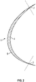
Fig. 1 illustrates a cross-section through a wind turbine blade and a preformed protective cover before attachment to the wind turbine blade, -
Fig. 2 illustrates on a larger scale a cross-section through the preformed protective cover ofFig. 1 , and -
Fig. 3 illustrates the preformed protective cover ofFig. 1 seen from its inside. -
Fig. 1 shows a preformed protective cover 1 for a wind turbine blade 2, wherein the preformed protective cover 1 is made of a polymer material, such as a polyether based polyurethane. The preformed protective cover 1 is adapted to be attached along at least a part of a longitudinal edge 3 of the wind turbine blade 2 by adhesion of an inside 4 of the preformed protective cover 1 to asurface 5 of the longitudinal edge 3 of the wind turbine blade 2. The preformed protective cover 1 is elongated in a longitudinal direction D and has an at least substantially U-formed cross-section. The preformed protective cover 1 includes acentral cover section 6 extending in the longitudinal direction D and two peripheral cover sections 7 extending in the longitudinal direction at either side of thecentral cover section 6, respectively. Thecentral cover section 6 has a minimum thickness of at least 1 millimetre, and each peripheral cover section 7 has a thickness decreasing from a maximum thickness of at least 1 millimetre to a minimum thickness of less than 1/2 millimetre. - The particular form of the peripheral cover sections 7 provides for a good transition from the central cover section of the preformed protective cover 1 to the surface of the wind turbine blade 2. A good transition without edges is of great importance in order to avoid that the wind will destroy the materials. A sealing material (sealer) may be applied in a possible groove between an edge of the peripheral cover sections 7 and the surface of the wind turbine blade 2 in order to even further improve the transition.
- The maximum thickness of each peripheral cover section 7 may correspond to the minimum thickness of the central cover section. The minimum thickness of the central cover section may be at least 2 millimetres, preferably at least 3 millimetres, more preferred at least 4 millimetres and most preferred approximately 5 millimetres.
- The thickness of the
central cover section 6 may be at least substantially constant from side to side of the central cover section. - The minimum thickness of each peripheral cover section 7 may be less than 1/3 millimetre, preferably less than 1/5 millimetres, more preferred less than 1/7 millimetres and most preferred approximately 1/10 millimetres.
- Each peripheral cover section 7 may have a thickness decreasing at least substantially constantly from its maximum thickness to its minimum thickness.
- The width of each peripheral cover section 7 may be at least 3 per cent, preferably at least 7 per cent, more preferred at least 12 per cent and most preferred at least 15 per cent of the total width of the preformed protective cover.
- The total width of the preformed protective cover 1 may be at least 30 millimetres, preferably at least 50 millimetres, more preferred at least 100 millimetres and most preferred approximately 150 to 250 millimetres.
- The total width of the preformed protective cover 1 may increase in the longitudinal direction as illustrated in
Fig. 3 . - The inside of the preformed protective cover 1 may be provided with a number of not shown protrusions having a height of between 1/2 and 2 millimetres, preferably approximately 1 millimetre. Such not shown protrusions may have the function of ensuring an appropriate layer thickness of adhesive between the preformed protective cover 1 and the surface of the wind turbine blade 2.
- The preformed protective cover may have a symmetry axis 8 extending in the longitudinal direction D. The inside of the preformed protective cover 1 at either side of the symmetry axis may be provided with a number of not shown spaced elongated protrusions extending with an oblique angle in relation to the longitudinal direction. Such not shown protrusions may in addition to the above-mentioned function have the function of leading the adhesive appropriately from the area around the symmetry axis 8 to the area of the peripheral cover sections 7.
- As seen in
Fig. 1 , the preformed protective cover 1 is adapted to be attached along at least a part of the longitudinal edge 3 of the wind turbine blade 2 by adhesion to thesurface 5 of the longitudinal edge of the wind turbine blade. - The wind turbine blade 2 may include a first blade shell 9 and a
second blade shell 10 joined together to form 2 wind turbine blade along a first longitudinal joint 11 at aleading edge 13 of the wind turbine blade and along a second longitudinal joint 12 at a trailingedge 14 of the wind turbine blade. The preformed protective cover 1 may be attached at least approximately symmetrical about the first or second longitudinal joint 11, 12, and preferably about the first longitudinal joint 11. - According to a method of providing a wind turbine blade with a preformed protective cover according to the invention, the preformed protective cover 1 is attached along at least a part of a longitudinal edge 3 of the wind turbine blade 2 by adhesion of the inside 4 of the preformed protective cover to a
surface 5 of the longitudinal edge of the wind turbine blade. The adhesion is performed by the following steps: - providing an adhesive, such as a two component polyurethane adhesive, on the inside 4 of the preformed protective cover 1,
- pressing the inside 4 of the preformed protective cover 1 against the
surface 5 of the longitudinal edge 3 of the wind turbine blade 2, and - removing excess adhesive leaking between each peripheral cover section 7 and the
surface 5 of the longitudinal edge 3 of the wind turbine blade 2. - The inside 4 of the preformed protective cover 1 may be pressed against the
surface 5 of the longitudinal edge 3 of the wind turbine blade 2 by means of a special tool. For instance, a tools may have a form corresponding to the outside of the preformed protective cover 1 and may be slid along the outside of the preformed protective cover in order to make the preformed protective cover fit as good as possible onto the wind turbine blade. - The adhesive may be provided as string of adhesive on the
inside 5 of the preformed protective cover 1 at least substantially along the longitudinal symmetry axis 8 of the preformed protective cover 1. By subsequently positioning the protective cover 1 on the wind turbine blade 2 and pressing on the protective cover 1 substantially along the longitudinal symmetry axis 8, the adhesive may be pressed in the direction of the peripheral cover sections 7 and thereby be suitably distributed. - The preformed protective cover 1 may be produced by the following steps:
- providing a not shown male form part having a geometry resembling or at least substantially matching the outer geometry of the at least part of the longitudinal edge 3 of the wind turbine blade 2,
- providing a not shown female form part having a geometry matching the male form part, but being slightly larger,
- closing the male form part against the female form part thereby forming a form cavity,
- pouring the adhesive into the form cavity, and
- opening the form cavity by separating the male form part from the female form part and ejecting the moulded preformed protective cover 1.
- The wind turbine blade 2 may be provided with the preformed protective cover 1 as a repair operation, whereby an area of said
surface 5 of the longitudinal edge 3 of the wind turbine blade 2 corresponding to the preformed protective cover 1 is machined, such as by grinding or milling, before attachment of the preformed protective cover 1. - The wind turbine blade 2 may be provided with the preformed protective cover 1 when the wind turbine blade 2 is still mounted on a wind turbine.
- Thereby, according to the invention, a damaged wind turbine blade 2 may be repaired in an advantageous way.
- The polyurethane material is prepared from a polyol, butanediol, and an isocyanate. The isocyanate may be an optionally modified diphenylmethane 4,4'-diisocyanate. The butanediol may be 1,4-butanediol. The polyurethane material may comprise an UV stabilisator and/or colour pigment(s).
- The protective cover for a wind turbine blade may be prepared by
- a) mixing a polyol and butanediol,
- b) tempering and degassing the mixture according to a),
- c) tempering and degassing an isocyanate,
- d) pumping the degassed mixture according to b) and the degasses isocyanate according to c) through a mixing head into a mould,
- e) curing in the mould, and
- f) demoulding the cured item.
- The tempering according to b) and/or c) may be carried out at a temperature from 30°C to 50°C. The tempering according to b) and/or c) may be carried out at a temperature about 40°C. The mould in step d) may be preheated. The mould in step d) may be preheated to a temperature from 90°C to 120°C. The mould in step d) may be preheated to a temperature about 100°C. The curing in step e) may be carried out at a temperature from 90°C to 120°C. The curing in step e) may be carried out at a temperature of about 100°C. The curing in step e) may be carried out for about 15 minutes. The process may comprise a further step: g) post-curing. The post-curing in step g) may take place in about 12 hours at a temperature of about 100°C. The polyurethane material or the process, the polyol, butanediol, and isocyanate may be used in a ratio by weight polyol:butanediol:isocyanate of 100:(3 to 5):(30 to 35). The polyol, butanediol, and isocyanate may be used in a ratio by weight polyol:butanediol:isocyanate of 100:4:32.3. The polyol comprises an UV stabilisator and/or colour pigment(s). The polyol may be Bayflex® OS 380-A-59A. The isocyanate may be DESMODUR® PF. Butanediol may be 1,4-butanediol.
- To elucidate the Rain Erosion (RE) durability of the polyurethane material according to the present invention, the durability of the material has been compared to other products.
- Annex A illustrates the result of a so-called rain erosion test performed on a sample part of a protective cover for a wind turbine blade made of the polyurethane material according to the present invention. The test has been performed according to ASTM G73-10.
- Annex A-1 illustrates the sample part on a larger scale, before start of the test.
- Annex A-2 illustrates the sample part at nine different stages of the test. "UV" indicates the number of hours the sample part has been exposed to UV light. "RE" indicates the number of hours the sample part has been exposed to the simulated rain erosion.
- Annex A-3 illustrates the sample part at the end of the test. The sample part has been exposed to UV light for 573 hours and has been exposed to the simulated rain erosion for 40 hours. It is seen that no erosion is visible.
- Annex B illustrates the result of a rain erosion test performed on a sample part of a protective cover for a wind turbine blade (Blade no. 1); said protective cover not being made of the polyurethane material according to the present invention. The test has been performed according to ASTM G73-10.
- Annex B-3 illustrates the sample part before start of the test.
- Annex B-4 illustrates the sample part when it has been exposed to the simulated rain erosion for 0.5 hours. It is seen that no erosion is visible.
- Annex B-5 illustrates the sample part when it has been exposed to the simulated rain erosion for 1 hour. It is seen that severe erosion is visible.
- Annex B-6 illustrates the sample part when it has been exposed to the simulated rain erosion for 5.0 hours. It is seen that severe erosion is visible.
- Annex B-7 illustrates the sample part when it has been exposed to the simulated rain erosion for 11.5 hours at the end of the test. It is seen that severe erosion is visible.
- Annex C illustrates the result of a rain erosion test performed on a sample part of a protective cover for a wind turbine blade (Blade no. 2); said protective cover not being made of the polyurethane material according to the present invention. The test has been performed according to ASTM G73-10.
- Annex C-2 illustrates the sample part before start of the test.
- Annex C-3 illustrates the sample part when it has been exposed to the simulated rain erosion for 5.0 hours. It is seen that severe erosion is visible.
- Annex C-4 illustrates the sample part when it has been exposed to the simulated rain erosion for 10.0 hours. It is seen that severe erosion is visible.
- Annex C-5 illustrates the sample part when it has been exposed to the simulated rain erosion for 21.0 hours at the end of the test. It is seen that severe erosion is visible.
- Annex D illustrates the result of a rain erosion test performed on a sample part of a protective cover for a wind turbine blade (Blade no. 3); said protective cover not being made of the polyurethane material according to the present invention. The test has been performed according to ASTM G73-10.
- Annex D-2 illustrates the sample part before start of the test.
- Annex D-3 illustrates the sample part when it has been exposed to the simulated rain erosion for 0.5 hours. It is seen that severe erosion is visible.
- Annex D-4 illustrates the sample part when it has been exposed to the simulated rain erosion for 1.5 hours. It is seen that severe erosion is visible.
- Annex D-5 illustrates the sample part when it has been exposed to the simulated rain erosion for 3.5 hours at the end of the test. It is seen that severe erosion is visible.
- Annex E-1 illustrates respective speeds during the tests performed.
- Annex E-2 illustrates respective temperatures during the tests performed.
- It is therefore seen that the durability of the polyurethane material according to the present invention is significantly higher than the other tested materials.


Claims (15)
- A preformed protective cover (1) for a wind turbine blade (2), wherein the preformed protective cover is made of a polyurethane material prepared from a polyol, butanediol, and an isocyanate, wherein the preformed protective cover is adapted to be attached along at least a part of a longitudinal edge (3) of the wind turbine blade by adhesion of an inside (4) of the preformed protective cover to a surface (5) of the longitudinal edge of the wind turbine blade, wherein the preformed protective cover is elongated in a longitudinal direction (D) and has an at least substantially U-formed cross-section, wherein the preformed protective cover includes a central cover section (6) extending in the longitudinal direction and two peripheral cover sections (7) extending in the longitudinal direction at either side of the central cover section (6), respectively, wherein the central cover section (6) has a minimum thickness, wherein each peripheral cover section has a maximum thickness, the maximum thickness corresponds to the minimum thickness of the central cover section.
- A preformed protective cover according to claim 1, wherein the thickness of the central cover section is at least substantially constant from side to side of the central cover section.
- A preformed protective cover according to claim 1 or 2, wherein each peripheral cover section has a thickness decreasing at least substantially constantly from its maximum thickness to its minimum thickness.
- A preformed protective cover according to any one of the claims 1 to 3, wherein the width of each peripheral cover section is at least 3 per cent, preferably at least 7 per cent, more preferred at least 12 per cent and most preferred at least 15 per cent of the total width of the preformed protective cover.
- A preformed protective cover according to any one of the claims 1 to 4, wherein the total width of the preformed protective cover is at least 30 millimetres, preferably at least 50 millimetres, more preferred at least 100 millimetres and most preferred approximately 150 to 250 millimetres.
- A preformed protective cover according to any one of the claims 1 to 5, wherein the total width of the preformed protective cover increases in the longitudinal direction.
- A preformed protective cover according to any one of the claims 1 to 6, wherein the inside of the preformed protective cover is provided with a number of protrusions having a height of between 1/2 and 2 millimetres, preferably approximately 1 millimetre.
- A preformed protective cover according to any one of the claims 1 to 7, wherein the preformed protective cover has a symmetry axis in the longitudinal direction, and wherein the inside of the preformed protective cover at either side of the symmetry axis is provided with a number of spaced elongated protrusions extending with an oblique angle in relation to the longitudinal direction.
- A preformed protective cover according to any one of the claims 1 to 8, wherein the isocyanate is an optionally modified diphenylmethane 4,4'-diisocyanate.
- A preformed protective cover according to any one of the claims 1 to 9, wherein the butanediol is 1,4-butanediol.
- A preformed protective cover according to any one of the claims 1 to 10, wherein the polyurethane comprises an UV stabilisator and/or colour pigment(s).
- A preformed protective cover according to any one of the claims 1 to 11, wherein the polyol, butanediol, and isocyanate are used in a ratio by weight polyol:butanediol:isocyanate of 100:(3 to 5):(30 to 35).
- A preformed protective cover according to any one of the claims 1 to 12, wherein the polyol comprises an UV stabilisator and/or colour pigment(s).
- A wind turbine blade including a preformed protective cover according to any one of the claims 1 to 13, wherein the preformed protective cover is attached along at least a part of a longitudinal edge of the wind turbine blade by adhesion to a surface of the longitudinal edge of the wind turbine blade.
- A wind turbine blade according to claim 14, wherein the wind turbine blade includes a first blade shell and a second blade shell joined together to form a wind turbine blade along a first longitudinal joint at a leading edge of the wind turbine blade and along a second longitudinal joint at a trailing edge of the wind turbine blade, and wherein the preformed protective cover is attached at least approximately symmetrical about the first or second longitudinal joint, and preferably about the first longitudinal joint.
Applications Claiming Priority (4)
| Application Number | Priority Date | Filing Date | Title |
|---|---|---|---|
| DKPA201400650 | 2014-11-10 | ||
| DKPA201500208 | 2015-04-01 | ||
| PCT/IB2015/058674 WO2016075619A1 (en) | 2014-11-10 | 2015-11-10 | Polyurethane material, process for preparing such material and protective cover for wind turbine blade |
| EP15797456.9A EP3218597B1 (en) | 2014-11-10 | 2015-11-10 | Polyurethane material, process for preparing such material and protective cover for wind turbine blade |
Related Parent Applications (1)
| Application Number | Title | Priority Date | Filing Date |
|---|---|---|---|
| EP15797456.9A Division EP3218597B1 (en) | 2014-11-10 | 2015-11-10 | Polyurethane material, process for preparing such material and protective cover for wind turbine blade |
Publications (1)
| Publication Number | Publication Date |
|---|---|
| EP3533816A1 true EP3533816A1 (en) | 2019-09-04 |
Family
ID=58731884
Family Applications (2)
| Application Number | Title | Priority Date | Filing Date |
|---|---|---|---|
| EP15797456.9A Active EP3218597B1 (en) | 2014-11-10 | 2015-11-10 | Polyurethane material, process for preparing such material and protective cover for wind turbine blade |
| EP19164579.5A Pending EP3533816A1 (en) | 2014-11-10 | 2015-11-10 | Preformed protective cover and wind turbine blade |
Family Applications Before (1)
| Application Number | Title | Priority Date | Filing Date |
|---|---|---|---|
| EP15797456.9A Active EP3218597B1 (en) | 2014-11-10 | 2015-11-10 | Polyurethane material, process for preparing such material and protective cover for wind turbine blade |
Country Status (10)
| Country | Link |
|---|---|
| US (1) | US11629689B2 (en) |
| EP (2) | EP3218597B1 (en) |
| JP (1) | JP2018503775A (en) |
| CN (1) | CN107207688A (en) |
| AU (1) | AU2015344705B2 (en) |
| BR (1) | BR112017009645B1 (en) |
| CA (1) | CA2966685C (en) |
| DK (1) | DK3218597T3 (en) |
| ES (1) | ES2726023T3 (en) |
| WO (1) | WO2016075619A1 (en) |
Families Citing this family (35)
| Publication number | Priority date | Publication date | Assignee | Title |
|---|---|---|---|---|
| DK201570881A1 (en) * | 2015-05-26 | 2017-01-30 | Blade Repair Solutions Ivs | A method for establishing erosion resistant surface on a wind turbine blade, process for the formation of an erosion-resistant coating, wind turbine blade with retrofitted coating in and around the areas where the wing is particularly prone to erosion damage coating for mounting on a wind turbine forefront. |
| BR112018072785B1 (en) | 2016-09-13 | 2022-10-25 | Polytech A/S | WIND TURBINE BLADES INCLUDING PROTECTIVE COVER AND METHOD OF SUPPLYING A WIND TURBINE BLADES WITH A PROTECTIVE COVER |
| WO2018060298A1 (en) * | 2016-09-27 | 2018-04-05 | Siemens Aktiengesellschaft | Adhesive protective cover system |
| CN110036199A (en) * | 2016-09-27 | 2019-07-19 | 西门子歌美飒可再生能源公司 | protective cover system |
| EP3357953A1 (en) | 2017-02-06 | 2018-08-08 | Nitto Denko Corporation | Composition and method for prevention of leading edge erosion in wind turbines |
| CN110691906B (en) * | 2017-05-31 | 2022-07-01 | 西门子歌美飒可再生能源公司 | Protective housing with positioning mark |
| WO2018228647A1 (en) * | 2017-06-16 | 2018-12-20 | Vestas Wind Systems A/S | Leading edge protection for a wind turbine blade |
| US10604234B2 (en) * | 2017-06-17 | 2020-03-31 | Bell Helicopter Textron Inc. | Method and apparatus to improve lift to drag ratio of a rotor blade |
| CN107120243B (en) * | 2017-06-19 | 2019-07-19 | 东方电气风电有限公司 | A kind of wind electricity blade production method based on graphene heating ice-melt |
| CN107489596B (en) * | 2017-08-11 | 2019-10-11 | 新疆金风科技股份有限公司 | Anti-freeze blade production method and wind generator set blade |
| DK179701B1 (en) * | 2017-09-06 | 2019-04-02 | Blade Repair Solutions Ivs | A method for reinforcing a wind turbine blade |
| CN107882697A (en) * | 2017-11-03 | 2018-04-06 | 索爱菊 | A kind of wind generator set blade anti-icing and deicing system |
| USD891351S1 (en) | 2017-12-15 | 2020-07-28 | Bell Helicopter Textron Inc. | Rotor blade |
| WO2019134862A1 (en) | 2018-01-03 | 2019-07-11 | Sika Technology Ag | Rotor blade protection |
| ES2954182T3 (en) * | 2018-03-08 | 2023-11-20 | Siemens Gamesa Renewable Energy As | Protective cover to protect a leading edge of a wind turbine blade |
| WO2019186220A1 (en) | 2018-03-27 | 2019-10-03 | Polytech A/S | A system for protecting a leading edge on a wind turbine rotor blade, a vacuum sheet for use in the system and a method for, in situ, protecting a part of a leading edge of a wind turbine rotor blade |
| ES2928695T3 (en) | 2018-05-11 | 2022-11-22 | Gen Electric | wind turbine operation |
| EP3620648A1 (en) | 2018-09-10 | 2020-03-11 | Siemens Gamesa Renewable Energy A/S | Method of providing an edge seal for a rotor blade add-on |
| CN109322784B (en) * | 2018-12-11 | 2023-05-09 | 江苏金风科技有限公司 | Front edge component of blade for wind generating set, blade and impeller |
| WO2020182763A1 (en) * | 2019-03-08 | 2020-09-17 | Siemens Gamesa Renewable Energy A/S | Method for creating a transition from an edge of an add-on part mounted on the outer surface of a rotor blade |
| EP3708828A1 (en) | 2019-03-14 | 2020-09-16 | Siemens Gamesa Renewable Energy A/S | A method for providing a wind turbine blade with lightning protection and a wind turbine blade |
| CN111894791A (en) * | 2019-05-06 | 2020-11-06 | 江苏金风科技有限公司 | Blade and wind generating set |
| EP3990262B1 (en) | 2019-06-26 | 2023-09-20 | Vestas Wind Systems A/S | Wind turbine blade leading edge protection method |
| EP3769940B1 (en) * | 2019-07-26 | 2023-08-09 | Polytech A/S | A system and method for attaching an add-on on a wind turbine blade |
| CN110439630B (en) * | 2019-08-12 | 2022-07-29 | 航天材料及工艺研究所 | Variable-thickness composite stator blade and forming method thereof |
| EP3822478A1 (en) * | 2019-11-15 | 2021-05-19 | Siemens Gamesa Renewable Energy A/S | Shell of a wind turbine blade |
| EP3865703A1 (en) | 2020-02-12 | 2021-08-18 | Siemens Gamesa Renewable Energy A/S | Wind turbine rotor blade leading-edge protector |
| CN111237124B (en) * | 2020-02-19 | 2021-11-05 | 上海电气风电集团股份有限公司 | System integrating wind power blade leading edge protection and lightning stroke protection |
| CN111305997B (en) * | 2020-03-18 | 2021-06-25 | 上海电气风电集团股份有限公司 | Wind power blade and manufacturing method thereof |
| WO2022083838A1 (en) | 2020-10-19 | 2022-04-28 | Vestas Wind Systems A/S | Method and tool for detecting defects on a wind turbine generator blade |
| WO2023280838A1 (en) * | 2021-07-06 | 2023-01-12 | Lm Wind Power A/S | Wind turbine blade having an electro-thermal system |
| CN114316201B (en) * | 2022-01-27 | 2023-12-22 | 浙江天和树脂有限公司 | Two-component polyurethane resin system |
| US11898541B2 (en) * | 2022-05-18 | 2024-02-13 | Pinnacle Lightning, LLC | Wind turbine blade with a lightning protection system |
| CN115822867B (en) * | 2023-02-01 | 2023-05-26 | 新创碳谷集团有限公司 | Modularized wind power blade structure and manufacturing method thereof |
| CN115977867B (en) * | 2023-03-20 | 2023-06-09 | 新创碳谷集团有限公司 | Sectional type blade module structure and forming method thereof |
Citations (7)
| Publication number | Priority date | Publication date | Assignee | Title |
|---|---|---|---|---|
| US4202957A (en) * | 1974-09-09 | 1980-05-13 | The Upjohn Company | Thermoplastic polyurethane elastomers from polyoxypropylene polyoxyethylene block copolymers |
| EP0037987A2 (en) | 1980-04-15 | 1981-10-21 | Messerschmitt-Bölkow-Blohm Gesellschaft mit beschränkter Haftung | Method for the manufacture of foamed core-supported moulded articles such as wings, rotor blades, etc. of great dimension in length and width |
| WO2004076852A2 (en) | 2003-02-28 | 2004-09-10 | Vestas Wind Systems A/S | Method of manufacturing a wind turbine blade, wind turbine blade, front cover and use of a front cover |
| ES2333929A1 (en) * | 2007-10-18 | 2010-03-02 | Fundacion Cener-Ciemat | Removable protection of the attack edge in a winder winger. (Machine-translation by Google Translate, not legally binding) |
| WO2010122157A1 (en) | 2009-04-24 | 2010-10-28 | Hempel A/S | Improved coating composition for wind turbine blades |
| US20120007270A1 (en) * | 2010-04-28 | 2012-01-12 | Bayer Materialscience Ag | Thermoplastic polyurethanes and their use |
| US20130045105A1 (en) | 2011-08-17 | 2013-02-21 | Howard Daniel Driver | Wind turbine blade and method of protecting the same |
Family Cites Families (30)
| Publication number | Priority date | Publication date | Assignee | Title |
|---|---|---|---|---|
| US3467572A (en) * | 1964-11-09 | 1969-09-16 | Du Pont | Constrained layer damped laminate structure |
| US3746689A (en) * | 1972-02-11 | 1973-07-17 | Basf Wyandotte Corp | Polyisocyanates blocked with polyhaloalcohols |
| US4123309A (en) * | 1973-11-29 | 1978-10-31 | Minnesota Mining And Manufacturing Company | Transfer letter system |
| US4727094A (en) * | 1983-09-27 | 1988-02-23 | Union Carbide Corporation | Method for producing polyurethanes |
| DK172126B1 (en) | 1995-10-25 | 1997-11-17 | Bonus Energy As | Windmill sail |
| EP1172387A1 (en) | 2000-07-14 | 2002-01-16 | Huntsman International Llc | Process for preparing an elastomer |
| US20040118978A1 (en) | 2002-12-24 | 2004-06-24 | Anning Bruce D. | Helicopter rotor and method of repairing same |
| US7357889B2 (en) | 2003-04-09 | 2008-04-15 | Lubrizol Advanced Materials, Inc. | Melt spun TPU fibers and process |
| JP4451109B2 (en) * | 2003-10-10 | 2010-04-14 | Sriスポーツ株式会社 | Golf ball |
| US10265932B2 (en) * | 2005-10-21 | 2019-04-23 | Entrotech, Inc. | Protective sheets, articles, and methods |
| US20070128445A1 (en) * | 2005-12-05 | 2007-06-07 | Lear Corporation | Method of making and inspecting an in mold coated article |
| US20120156049A1 (en) | 2005-12-14 | 2012-06-21 | Hong Shek C | Method and coating for protecting and repairing an airfoil surface |
| DE102006016617B4 (en) * | 2006-04-06 | 2008-02-28 | Carl Freudenberg Kg | Polyurethane molding, process for its preparation and its use |
| US20080176083A1 (en) | 2007-01-18 | 2008-07-24 | Noveon, Inc. | High Moisture Vapor Transmissive Polyurethanes |
| CN101802039A (en) * | 2007-07-12 | 2010-08-11 | 陶氏环球技术公司 | prepolymers and polymers for elastomers |
| US8096508B2 (en) | 2007-08-10 | 2012-01-17 | 3M Innovative Properties Company | Erosion resistant films for use on heated aerodynamic surfaces |
| US9031801B2 (en) * | 2008-09-29 | 2015-05-12 | Mitsumi Electric Co., Ltd. | Portable device, battery pack, display controlling method, and display controlling program |
| WO2010048370A1 (en) * | 2008-10-22 | 2010-04-29 | Vec Industries, L.L.C. | Wind turbine blade and method for manufacturing thereof |
| JP2011052683A (en) | 2009-08-07 | 2011-03-17 | Nitto Denko Corp | Protective film for blade of wind power generator |
| KR101815330B1 (en) * | 2009-12-29 | 2018-01-04 | 쓰리엠 이노베이티브 프로퍼티즈 컴파니 | Polyurethane nanocomposites |
| US20110142678A1 (en) | 2010-11-23 | 2011-06-16 | General Electric Company | Erosion protection coating for rotor blade of wind turbine |
| US20120163981A1 (en) | 2010-12-22 | 2012-06-28 | Hong Shek C | Method and coating for protecting and repairing an airfoil surface |
| WO2013012699A2 (en) | 2011-07-15 | 2013-01-24 | 3M Innovative Properties Company | Polyurethane based coating compositions |
| EP2551314B1 (en) | 2011-07-29 | 2014-07-23 | 3M Innovative Properties Company | Profiled protective tape for rotor blades of wind turbine generators |
| CN108997740A (en) * | 2011-12-19 | 2018-12-14 | 陶氏环球技术有限责任公司 | The thermoset polyurethane foam of the agent of polymeric flame-retardant containing bromination |
| WO2013092211A1 (en) | 2011-12-19 | 2013-06-27 | Lm Wind Power A/S | An erosion shield for a wind turbine blade |
| US9512818B2 (en) * | 2012-01-18 | 2016-12-06 | Pika Energy LLC | Low-cost molded wind turbine blade |
| US9732252B2 (en) | 2012-05-15 | 2017-08-15 | 3M Innovative Properties Company | Polyurethane-based protective coatings for rotor blades |
| EP2868920A4 (en) | 2012-12-27 | 2015-08-05 | Mitsubishi Heavy Ind Ltd | Wind turbine rotor blade and wind turbine generator with same |
| EP2927482A1 (en) | 2014-04-01 | 2015-10-07 | LM WP Patent Holding A/S | A wind turbine blade provided with an erosion shield |
-
2015
- 2015-11-10 CA CA2966685A patent/CA2966685C/en active Active
- 2015-11-10 EP EP15797456.9A patent/EP3218597B1/en active Active
- 2015-11-10 DK DK15797456.9T patent/DK3218597T3/en active
- 2015-11-10 EP EP19164579.5A patent/EP3533816A1/en active Pending
- 2015-11-10 JP JP2017544061A patent/JP2018503775A/en active Pending
- 2015-11-10 CN CN201580069764.9A patent/CN107207688A/en active Pending
- 2015-11-10 AU AU2015344705A patent/AU2015344705B2/en active Active
- 2015-11-10 US US15/525,244 patent/US11629689B2/en active Active
- 2015-11-10 WO PCT/IB2015/058674 patent/WO2016075619A1/en active Application Filing
- 2015-11-10 ES ES15797456T patent/ES2726023T3/en active Active
- 2015-11-10 BR BR112017009645-5A patent/BR112017009645B1/en active IP Right Grant
Patent Citations (7)
| Publication number | Priority date | Publication date | Assignee | Title |
|---|---|---|---|---|
| US4202957A (en) * | 1974-09-09 | 1980-05-13 | The Upjohn Company | Thermoplastic polyurethane elastomers from polyoxypropylene polyoxyethylene block copolymers |
| EP0037987A2 (en) | 1980-04-15 | 1981-10-21 | Messerschmitt-Bölkow-Blohm Gesellschaft mit beschränkter Haftung | Method for the manufacture of foamed core-supported moulded articles such as wings, rotor blades, etc. of great dimension in length and width |
| WO2004076852A2 (en) | 2003-02-28 | 2004-09-10 | Vestas Wind Systems A/S | Method of manufacturing a wind turbine blade, wind turbine blade, front cover and use of a front cover |
| ES2333929A1 (en) * | 2007-10-18 | 2010-03-02 | Fundacion Cener-Ciemat | Removable protection of the attack edge in a winder winger. (Machine-translation by Google Translate, not legally binding) |
| WO2010122157A1 (en) | 2009-04-24 | 2010-10-28 | Hempel A/S | Improved coating composition for wind turbine blades |
| US20120007270A1 (en) * | 2010-04-28 | 2012-01-12 | Bayer Materialscience Ag | Thermoplastic polyurethanes and their use |
| US20130045105A1 (en) | 2011-08-17 | 2013-02-21 | Howard Daniel Driver | Wind turbine blade and method of protecting the same |
Also Published As
| Publication number | Publication date |
|---|---|
| CA2966685A1 (en) | 2016-05-19 |
| DK3218597T3 (en) | 2019-06-03 |
| JP2018503775A (en) | 2018-02-08 |
| BR112017009645B1 (en) | 2022-09-27 |
| CN107207688A (en) | 2017-09-26 |
| US20170314532A1 (en) | 2017-11-02 |
| AU2015344705A1 (en) | 2017-05-25 |
| EP3218597A1 (en) | 2017-09-20 |
| BR112017009645A2 (en) | 2017-12-19 |
| US11629689B2 (en) | 2023-04-18 |
| ES2726023T3 (en) | 2019-10-01 |
| AU2015344705B2 (en) | 2018-08-23 |
| CA2966685C (en) | 2021-01-12 |
| EP3218597B1 (en) | 2019-03-27 |
| WO2016075619A1 (en) | 2016-05-19 |
Similar Documents
| Publication | Publication Date | Title |
|---|---|---|
| EP3218597B1 (en) | Polyurethane material, process for preparing such material and protective cover for wind turbine blade | |
| EP3027385B1 (en) | Erosion resistant aerodynamic fairing | |
| CN108025519B (en) | Wind turbine blade with erosion shield | |
| EP2927482A1 (en) | A wind turbine blade provided with an erosion shield | |
| EP2514961B1 (en) | Spoiler for a wind turbine rotor blade | |
| US20190226458A1 (en) | Aerodynamic Shroud and Method | |
| US20220235736A1 (en) | Longitudinal edge extension | |
| CN113635587B (en) | Method of manufacturing a wind turbine rotor blade | |
| JP2021525336A (en) | How to Repair the Leading Edge of Wind Turbine Blades | |
| US11371483B2 (en) | Method of manufacturing a shell of a wind turbine blade having improved leading edge erosion protection, method for manufacturing the wind turbine blade, shell, wind turbine blade and wind turbine | |
| JP2023546459A (en) | Wind turbine rotor blade with leading edge member | |
| US20240100794A1 (en) | A wind turbine blade with a fairing | |
| JP2024515554A (en) | Wind turbine blade with fairing |
Legal Events
| Date | Code | Title | Description |
|---|---|---|---|
| PUAI | Public reference made under article 153(3) epc to a published international application that has entered the european phase |
Free format text: ORIGINAL CODE: 0009012 |
|
| STAA | Information on the status of an ep patent application or granted ep patent |
Free format text: STATUS: THE APPLICATION HAS BEEN PUBLISHED |
|
| AC | Divisional application: reference to earlier application |
Ref document number: 3218597 Country of ref document: EP Kind code of ref document: P |
|
| AK | Designated contracting states |
Kind code of ref document: A1 Designated state(s): AL AT BE BG CH CY CZ DE DK EE ES FI FR GB GR HR HU IE IS IT LI LT LU LV MC MK MT NL NO PL PT RO RS SE SI SK SM TR |
|
| STAA | Information on the status of an ep patent application or granted ep patent |
Free format text: STATUS: REQUEST FOR EXAMINATION WAS MADE |
|
| 17P | Request for examination filed |
Effective date: 20200303 |
|
| RBV | Designated contracting states (corrected) |
Designated state(s): AL AT BE BG CH CY CZ DE DK EE ES FI FR GB GR HR HU IE IS IT LI LT LU LV MC MK MT NL NO PL PT RO RS SE SI SK SM TR |
|
| STAA | Information on the status of an ep patent application or granted ep patent |
Free format text: STATUS: EXAMINATION IS IN PROGRESS |
|
| 17Q | First examination report despatched |
Effective date: 20220223 |
|
| GRAP | Despatch of communication of intention to grant a patent |
Free format text: ORIGINAL CODE: EPIDOSNIGR1 |
|
| RIC1 | Information provided on ipc code assigned before grant |
Ipc: C08L 75/04 20060101ALI20240223BHEP Ipc: C08G 18/76 20060101ALI20240223BHEP Ipc: C08G 18/32 20060101ALI20240223BHEP Ipc: B29D 99/00 20100101ALI20240223BHEP Ipc: C08J 5/12 20060101ALI20240223BHEP Ipc: F03D 1/06 20060101ALI20240223BHEP Ipc: C08G 18/65 20060101AFI20240223BHEP |
|
| STAA | Information on the status of an ep patent application or granted ep patent |
Free format text: STATUS: GRANT OF PATENT IS INTENDED |