EP3027385B1 - Erosion resistant aerodynamic fairing - Google Patents
Erosion resistant aerodynamic fairing Download PDFInfo
- Publication number
- EP3027385B1 EP3027385B1 EP14749968.5A EP14749968A EP3027385B1 EP 3027385 B1 EP3027385 B1 EP 3027385B1 EP 14749968 A EP14749968 A EP 14749968A EP 3027385 B1 EP3027385 B1 EP 3027385B1
- Authority
- EP
- European Patent Office
- Prior art keywords
- erosion resistant
- fairing
- thermoplastic film
- resin
- layer
- Prior art date
- Legal status (The legal status is an assumption and is not a legal conclusion. Google has not performed a legal analysis and makes no representation as to the accuracy of the status listed.)
- Active
Links
- 230000003628 erosive effect Effects 0.000 title claims description 70
- 229920001169 thermoplastic Polymers 0.000 claims description 42
- 239000004416 thermosoftening plastic Substances 0.000 claims description 42
- 239000000835 fiber Substances 0.000 claims description 37
- 239000000758 substrate Substances 0.000 claims description 31
- 229920005989 resin Polymers 0.000 claims description 26
- 239000011347 resin Substances 0.000 claims description 26
- 239000002131 composite material Substances 0.000 claims description 17
- 238000000034 method Methods 0.000 claims description 13
- 230000003014 reinforcing effect Effects 0.000 claims description 12
- 239000004814 polyurethane Substances 0.000 claims description 7
- 229920002635 polyurethane Polymers 0.000 claims description 7
- 125000001931 aliphatic group Chemical group 0.000 claims description 5
- 238000004519 manufacturing process Methods 0.000 claims description 5
- 238000010438 heat treatment Methods 0.000 claims description 4
- 239000011159 matrix material Substances 0.000 claims description 2
- 238000003825 pressing Methods 0.000 claims description 2
- 238000005266 casting Methods 0.000 claims 1
- 239000010410 layer Substances 0.000 description 33
- 239000004721 Polyphenylene oxide Substances 0.000 description 4
- 239000003822 epoxy resin Substances 0.000 description 4
- 239000003973 paint Substances 0.000 description 4
- 229920000647 polyepoxide Polymers 0.000 description 4
- 229920000728 polyester Polymers 0.000 description 4
- 229920000570 polyether Polymers 0.000 description 4
- 230000001681 protective effect Effects 0.000 description 3
- 238000013459 approach Methods 0.000 description 2
- -1 caprolactone glycols Chemical class 0.000 description 2
- 239000011248 coating agent Substances 0.000 description 2
- 238000000576 coating method Methods 0.000 description 2
- 230000001419 dependent effect Effects 0.000 description 2
- 239000003365 glass fiber Substances 0.000 description 2
- 230000003301 hydrolyzing effect Effects 0.000 description 2
- 230000007774 longterm Effects 0.000 description 2
- 239000011241 protective layer Substances 0.000 description 2
- 239000000126 substance Substances 0.000 description 2
- OKTJSMMVPCPJKN-UHFFFAOYSA-N Carbon Chemical compound [C] OKTJSMMVPCPJKN-UHFFFAOYSA-N 0.000 description 1
- 239000004820 Pressure-sensitive adhesive Substances 0.000 description 1
- 229910052799 carbon Inorganic materials 0.000 description 1
- 230000003749 cleanliness Effects 0.000 description 1
- 238000013461 design Methods 0.000 description 1
- 239000000428 dust Substances 0.000 description 1
- 230000000694 effects Effects 0.000 description 1
- 230000002708 enhancing effect Effects 0.000 description 1
- 239000004744 fabric Substances 0.000 description 1
- 238000009472 formulation Methods 0.000 description 1
- 239000011521 glass Substances 0.000 description 1
- 239000004519 grease Substances 0.000 description 1
- LNEPOXFFQSENCJ-UHFFFAOYSA-N haloperidol Chemical compound C1CC(O)(C=2C=CC(Cl)=CC=2)CCN1CCCC(=O)C1=CC=C(F)C=C1 LNEPOXFFQSENCJ-UHFFFAOYSA-N 0.000 description 1
- 238000012423 maintenance Methods 0.000 description 1
- 239000000463 material Substances 0.000 description 1
- 239000000203 mixture Substances 0.000 description 1
- 238000000465 moulding Methods 0.000 description 1
- 238000012545 processing Methods 0.000 description 1
- 238000005728 strengthening Methods 0.000 description 1
- 239000012815 thermoplastic material Substances 0.000 description 1
- PAPBSGBWRJIAAV-UHFFFAOYSA-N ε-Caprolactone Chemical compound O=C1CCCCCO1 PAPBSGBWRJIAAV-UHFFFAOYSA-N 0.000 description 1
Images


Classifications
-
- F—MECHANICAL ENGINEERING; LIGHTING; HEATING; WEAPONS; BLASTING
- F03—MACHINES OR ENGINES FOR LIQUIDS; WIND, SPRING, OR WEIGHT MOTORS; PRODUCING MECHANICAL POWER OR A REACTIVE PROPULSIVE THRUST, NOT OTHERWISE PROVIDED FOR
- F03D—WIND MOTORS
- F03D1/00—Wind motors with rotation axis substantially parallel to the air flow entering the rotor
- F03D1/06—Rotors
- F03D1/065—Rotors characterised by their construction elements
- F03D1/0675—Rotors characterised by their construction elements of the blades
-
- B—PERFORMING OPERATIONS; TRANSPORTING
- B29—WORKING OF PLASTICS; WORKING OF SUBSTANCES IN A PLASTIC STATE IN GENERAL
- B29C—SHAPING OR JOINING OF PLASTICS; SHAPING OF MATERIAL IN A PLASTIC STATE, NOT OTHERWISE PROVIDED FOR; AFTER-TREATMENT OF THE SHAPED PRODUCTS, e.g. REPAIRING
- B29C70/00—Shaping composites, i.e. plastics material comprising reinforcements, fillers or preformed parts, e.g. inserts
- B29C70/003—Shaping composites, i.e. plastics material comprising reinforcements, fillers or preformed parts, e.g. inserts characterised by the matrix material, e.g. material composition or physical properties
- B29C70/0035—Shaping composites, i.e. plastics material comprising reinforcements, fillers or preformed parts, e.g. inserts characterised by the matrix material, e.g. material composition or physical properties comprising two or more matrix materials
-
- B—PERFORMING OPERATIONS; TRANSPORTING
- B29—WORKING OF PLASTICS; WORKING OF SUBSTANCES IN A PLASTIC STATE IN GENERAL
- B29C—SHAPING OR JOINING OF PLASTICS; SHAPING OF MATERIAL IN A PLASTIC STATE, NOT OTHERWISE PROVIDED FOR; AFTER-TREATMENT OF THE SHAPED PRODUCTS, e.g. REPAIRING
- B29C70/00—Shaping composites, i.e. plastics material comprising reinforcements, fillers or preformed parts, e.g. inserts
- B29C70/04—Shaping composites, i.e. plastics material comprising reinforcements, fillers or preformed parts, e.g. inserts comprising reinforcements only, e.g. self-reinforcing plastics
- B29C70/06—Fibrous reinforcements only
- B29C70/08—Fibrous reinforcements only comprising combinations of different forms of fibrous reinforcements incorporated in matrix material, forming one or more layers, and with or without non-reinforced layers
- B29C70/086—Fibrous reinforcements only comprising combinations of different forms of fibrous reinforcements incorporated in matrix material, forming one or more layers, and with or without non-reinforced layers and with one or more layers of pure plastics material, e.g. foam layers
-
- B—PERFORMING OPERATIONS; TRANSPORTING
- B29—WORKING OF PLASTICS; WORKING OF SUBSTANCES IN A PLASTIC STATE IN GENERAL
- B29K—INDEXING SCHEME ASSOCIATED WITH SUBCLASSES B29B, B29C OR B29D, RELATING TO MOULDING MATERIALS OR TO MATERIALS FOR MOULDS, REINFORCEMENTS, FILLERS OR PREFORMED PARTS, e.g. INSERTS
- B29K2063/00—Use of EP, i.e. epoxy resins or derivatives thereof, as moulding material
-
- B—PERFORMING OPERATIONS; TRANSPORTING
- B29—WORKING OF PLASTICS; WORKING OF SUBSTANCES IN A PLASTIC STATE IN GENERAL
- B29K—INDEXING SCHEME ASSOCIATED WITH SUBCLASSES B29B, B29C OR B29D, RELATING TO MOULDING MATERIALS OR TO MATERIALS FOR MOULDS, REINFORCEMENTS, FILLERS OR PREFORMED PARTS, e.g. INSERTS
- B29K2105/00—Condition, form or state of moulded material or of the material to be shaped
- B29K2105/06—Condition, form or state of moulded material or of the material to be shaped containing reinforcements, fillers or inserts
- B29K2105/08—Condition, form or state of moulded material or of the material to be shaped containing reinforcements, fillers or inserts of continuous length, e.g. cords, rovings, mats, fabrics, strands or yarns
- B29K2105/0872—Prepregs
- B29K2105/089—Prepregs fabric
-
- B—PERFORMING OPERATIONS; TRANSPORTING
- B29—WORKING OF PLASTICS; WORKING OF SUBSTANCES IN A PLASTIC STATE IN GENERAL
- B29K—INDEXING SCHEME ASSOCIATED WITH SUBCLASSES B29B, B29C OR B29D, RELATING TO MOULDING MATERIALS OR TO MATERIALS FOR MOULDS, REINFORCEMENTS, FILLERS OR PREFORMED PARTS, e.g. INSERTS
- B29K2309/00—Use of inorganic materials not provided for in groups B29K2303/00 - B29K2307/00, as reinforcement
- B29K2309/08—Glass
-
- B—PERFORMING OPERATIONS; TRANSPORTING
- B29—WORKING OF PLASTICS; WORKING OF SUBSTANCES IN A PLASTIC STATE IN GENERAL
- B29K—INDEXING SCHEME ASSOCIATED WITH SUBCLASSES B29B, B29C OR B29D, RELATING TO MOULDING MATERIALS OR TO MATERIALS FOR MOULDS, REINFORCEMENTS, FILLERS OR PREFORMED PARTS, e.g. INSERTS
- B29K2675/00—Use of PU, i.e. polyureas or polyurethanes or derivatives thereof, for preformed parts, e.g. for inserts
-
- B—PERFORMING OPERATIONS; TRANSPORTING
- B29—WORKING OF PLASTICS; WORKING OF SUBSTANCES IN A PLASTIC STATE IN GENERAL
- B29L—INDEXING SCHEME ASSOCIATED WITH SUBCLASS B29C, RELATING TO PARTICULAR ARTICLES
- B29L2031/00—Other particular articles
- B29L2031/08—Blades for rotors, stators, fans, turbines or the like, e.g. screw propellers
- B29L2031/082—Blades, e.g. for helicopters
- B29L2031/085—Wind turbine blades
-
- F—MECHANICAL ENGINEERING; LIGHTING; HEATING; WEAPONS; BLASTING
- F05—INDEXING SCHEMES RELATING TO ENGINES OR PUMPS IN VARIOUS SUBCLASSES OF CLASSES F01-F04
- F05B—INDEXING SCHEME RELATING TO WIND, SPRING, WEIGHT, INERTIA OR LIKE MOTORS, TO MACHINES OR ENGINES FOR LIQUIDS COVERED BY SUBCLASSES F03B, F03D AND F03G
- F05B2260/00—Function
- F05B2260/95—Preventing corrosion
-
- F—MECHANICAL ENGINEERING; LIGHTING; HEATING; WEAPONS; BLASTING
- F05—INDEXING SCHEMES RELATING TO ENGINES OR PUMPS IN VARIOUS SUBCLASSES OF CLASSES F01-F04
- F05B—INDEXING SCHEME RELATING TO WIND, SPRING, WEIGHT, INERTIA OR LIKE MOTORS, TO MACHINES OR ENGINES FOR LIQUIDS COVERED BY SUBCLASSES F03B, F03D AND F03G
- F05B2280/00—Materials; Properties thereof
- F05B2280/70—Treatments or modification of materials
- F05B2280/702—Reinforcements
-
- Y—GENERAL TAGGING OF NEW TECHNOLOGICAL DEVELOPMENTS; GENERAL TAGGING OF CROSS-SECTIONAL TECHNOLOGIES SPANNING OVER SEVERAL SECTIONS OF THE IPC; TECHNICAL SUBJECTS COVERED BY FORMER USPC CROSS-REFERENCE ART COLLECTIONS [XRACs] AND DIGESTS
- Y02—TECHNOLOGIES OR APPLICATIONS FOR MITIGATION OR ADAPTATION AGAINST CLIMATE CHANGE
- Y02E—REDUCTION OF GREENHOUSE GAS [GHG] EMISSIONS, RELATED TO ENERGY GENERATION, TRANSMISSION OR DISTRIBUTION
- Y02E10/00—Energy generation through renewable energy sources
- Y02E10/70—Wind energy
- Y02E10/72—Wind turbines with rotation axis in wind direction
-
- Y—GENERAL TAGGING OF NEW TECHNOLOGICAL DEVELOPMENTS; GENERAL TAGGING OF CROSS-SECTIONAL TECHNOLOGIES SPANNING OVER SEVERAL SECTIONS OF THE IPC; TECHNICAL SUBJECTS COVERED BY FORMER USPC CROSS-REFERENCE ART COLLECTIONS [XRACs] AND DIGESTS
- Y02—TECHNOLOGIES OR APPLICATIONS FOR MITIGATION OR ADAPTATION AGAINST CLIMATE CHANGE
- Y02P—CLIMATE CHANGE MITIGATION TECHNOLOGIES IN THE PRODUCTION OR PROCESSING OF GOODS
- Y02P70/00—Climate change mitigation technologies in the production process for final industrial or consumer products
- Y02P70/50—Manufacturing or production processes characterised by the final manufactured product
Definitions
- the present invention relates to an erosion resistant aerodynamic fairing and more particularly to an erosion resistant aerodynamic fairing for a rotor blade.
- the present invention is described herein by way of a practical example as an erosion resistant aerodynamic fairing for a wind turbine blade. However, it is readily applicable to other types of erosion-exposed surfaces, such as helicopter rotor blades, or fan blades.
- a further known example of an erosion protection measure for wind turbine blades is the use of metallic leading edges.
- metallic leading edges also increase the local stiffness of the blade, which can worsen aerodynamic performance, and can complicate the lightning protection systems required for the blade due to their conductive nature.
- thermoplastic film 120 it is also known to apply a protective layer of thermoplastic film over the leading edge of a wind turbine blade.
- Figure 1 shows the leading edge 118 of a fairing 110 for a wind turbine blade to which a protective layer of thermoplastic film 120 is fixed.
- the fairing 110 is formed from a composite laminate body 112 and the thermoplastic film 120 is post applied to the leading edge 118 as a thin (150mm wide) tape with a layer of pressure sensitive adhesive 119.
- Such films offer good erosion resistance but are difficult to apply.
- the quality of the bond between the thermoplastic film 120 and the laminate body 112 is dependent on the surface of the fairing 110 being free from grease and dust etc.
- thermoplastic film it is known to fix the thermoplastic film to the blade during the moulding of the fairing as disclosed in International Publication No. WO2006/066593 .
- layers of reinforcing fibre are placed on top of a film laid out against the mould surface, following which resin is applied to join the layers.
- a further known example of an erosion resistant fairing can be found in International Publication No. WO2010/117262 .
- This fairing comprises a composite body formed from fibre-reinforced blade shells and a protective cover formed of a thermoplastic layer, a glass fibre mat and a cured epoxy resin layer.
- the composite body and the protective cover are formed separately and the protective cover is set in a recess in the composite body before the two components are fixed together using a layer of heat curable epoxy resin.
- this approach requires precise tolerance control of the parts to ensure that they fit together correctly and, as with the application of a thermoplastic film, the quality of the bond between the cover and the composite body is not easily controlled since it is dependent on the cleanliness of the attached surfaces.
- an erosion resistant aerodynamic fairing for a rotor blade according to the subject-matter of claim 1.
- the thermoplastic film may comprise any suitable thermoplastic material, for example polyurethane.
- the thermoplastic film comprises an aliphatic polyurethane.
- these types of polyurethane have been found to possess particularly good erosion resistant properties, hydrolytic stability and low temperature flexibility, making them well suited for use in aerodynamic fairings. The surface energy of these materials also allows them to bond well with epoxy resins, further enhancing the fixation of the erosion resistant layer to the composite body.
- the aliphatic polyurethane comprises long and short chain polyether, polyester, or caprolactone glycols, or a combination thereof from the composite body in the same manner as the thermoplastic film 120 shown in Figure 1 .
- the film has a textured outer surface.
- a textured outer surface i.e. the surface which comes into contact with the mould during manufacture, air can easily escape when the pre-form is placed in the mould and a vacuum applied. This results in a further improvement to the quality of the final erosion resistant fairing.
- the surface texture may be any suitable arrangement.
- the surface texture comprises a plurality of protrusions which may comprise a plurality of square and/or pyramid shaped protrusions preferably arranged in a regular array. This has been found to result in a particularly high quality fairing.
- the erosion resistant layer is set in and fixed to the outer surface of the fairing body such that the edges of the erosion resistant layer are flush with the fairing body.
- the erosion resistant layer has no free edges, reducing the risk of the thermoplastic film peeling off from its edges and avoiding aerodynamic steps across the outer surface of the fairing which may otherwise worsen aerodynamic performance.
- the erosion resistant layer may be applied to the entire length of a rotor blade.
- the erosion resistant layer is substantially confined to the outermost third of the blade length.
- the blade may still include one or more patches of erosion resistant layer inward of the outermost third of the blade length, for example to protect the blade in areas of locally high erosion.
- the erosion resistant layer may be fixed to the composite body over the entire profile of a rotor blade, or over a particular part of the rotor blade, such as the trailing edge.
- the erosion resistant layer is fixed to the fairing body at the leading edge of the rotor blade.
- thermoplastic film may be extruded or film cast directly onto the fibre substrate.
- the step of fusing the thermoplastic film to the fibre substrate comprises heating the thermoplastic film and the fibre substrate at a temperature of at least 60°C and pressing them together. This ensures that the thermoplastic film is strongly fused to the fibre substrate.
- the film and substrate are fused together at a temperature of between 60°C and 150°C. This ensures that the thermoplastic film is strongly fused to the fibre substrate and also avoids the loss of shape of the thermoplastic film which may occur at higher temperatures, thus providing a high quality surface finish.
- the pre-from and the fairing body may be joined together without any significant heating of the thermoplastic film.
- the thermoplastic film is heated to above its Vicat softening temperature before the resin reaches its minimum viscosity.
- the step of impregnating the reinforcing fibre layer may include impregnating the reinforcing fibre layer with the curable resin after placing the reinforcing fibre layer into the mould.
- the reinforcing fibre layer may be infused with the resin under a vacuum.
- the step of impregnating the reinforcing fibre layer includes pre-impregnating the reinforcing fibre layer with the curable resin before placing the reinforcing fibre layer into the mould. This allows a highly controlled resin content and improved process reliability and repeatability, reduced process times and allows the use of higher performance resins to improve the mechanical performance of the fairing.
- the fibre substrate may be inserted into the mould without any resin having been applied to it beforehand. Using this approach, as the stack of the pre-form and the uncured composite body is cured, the resin migrates from the uncured composite to impregnate the fibre substrate before curing to fix the erosion resistant layer to the fairing body. Alternatively, the fibre substrate may be pre-impregnated with the curable resin before placing the pre-form into the mould.
- the resin may impregnate the fibre substrate only partially. This will still result in a firm bond between the erosion resistant layer and the fairing body.
- the resin fully impregnates the fibre substrate during the curing step. This enables the resin to provide an additional chemical connection to the thermoplastic film to improve the fixation of the thermoplastic film to the fairing.
- the erosion resistant layer and the uncured composite may be cured together, or "co-cured", at any suitable temperature.
- the curing step comprises heating the curable resin to a temperature of from 60°C to 130°C. This allows a firm fixation between the two layers but prevents the distortion of the thermoplastic film and poor surface finish which may result from higher temperatures.
- the method further comprises the step of applying a surface texture to the outer surface of the thermoplastic film prior to the step of placing the pre-form in the mould, more preferably during the step of fusing the thermoplastic film to the fibre substrate to form the pre-form.
- the surface texture allows air to more easily escape when the pre-form is placed in the mould and a vacuum applied. This results in a further improvement to the quality of the final erosion resistant fairing.
- the surface texture may be any suitable arrangement.
- the surface texture comprises a plurality of protrusions which may comprise a plurality of square and/or pyramid shaped protrusions preferably arranged in a regular array. This has been found to result in a particularly high quality fairing.
- an erosion resistant aerodynamic fairing 10 is shown.
- the erosion resistant aerodynamic fairing 10 is formed from a fairing body 12 and an erosion resistant pre-form 14 fixed to an outer surface 16 of the fairing body 12 at the leading edge 18 of the fairing 10.
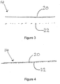
- the erosion resistant pre-form 14 comprises a thermoplastic film 20 outer layer fused to a fibre substrate 22.
- the thermoplastic film 20 is formed from an aliphatic polyurethane, which is approximately 600 microns thick and may be produced using long and short chain polyether, polyester, or caprolactone glycols.
- the polyether types have better hydrolytic stability and low-temperature flexibility
- the polyester types have better mechanical properties
- caprolactones offer a good compromise between the properties of the polyether and polyester types.
- caprolactone gycols are used. This results in film 20 having a Shore A hardness of approximately 75 to 95, an elongation of at least 300% and a surface energy in the region of 40 to 44 mN/m.
- the fibre substrate 22 is a glass fibre fabric pre-form which is multiaxial and has a weight of approximately 150 g/m 2
- thermoplastic film 20 and the fibre substrate 22 are heated to a temperature of 60 to 150°C and pressed together under an additional pressure of approximately 1 bar for approximately 60 seconds. This causes the film 20 and substrate 22 to fuse together, forming the erosion resistant pre-form 14, as shown in Figure 3 .
- the fusing process creates a very strong connection between the film 20 and the substrate 22.
- the erosion resistant pre-form 14 is very flexible and can easily be placed into a mould for a complex shape, such as for a wind turbine blade leading edge.
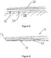
- the erosion resistant pre-form 14 is placed into a mould 24 with the thermoplastic film 20 against the surface of the mould 24.
- the erosion resistant pre-form 14 and the layers of pre-preg 26 are then co-cured under a vacuum and at a temperature of between 60 to 130°C for approximately 12 hours in the same manner as for normal pre-preg processing.
- resin from the pre-preg 26 migrates into and impregnates the fibre substrate 22.
- the resin then fully cures to form the fairing body 12 from the pre-preg 26 and to fix the erosion resistant pre-form 14 to the composite body 12. In doing so, the resin forms a continuous matrix through the composite body 12 and the erosion resistant pre-form 14 to firmly bond the two layers together.
- the resin also forms a chemical connection with the thermoplastic film 20, further strengthening the fixation of the erosion resistant pre-form 14 to the composite body 12.
- the resulting interface between the fairing body 12 and the erosion resistant pre-form 14 is well controlled and the fairing body 12 and fibre substrate 22 provide a very high quality substrate directly beneath the thermoplastic film 20 to improve long term erosion performance.
- the fairing body 12 Since the fairing body 12 and the erosion resistant pre-from 14 are co-cured, the fairing body 12 is shaped around the erosion resistant pre-form 14 so that the edges of the erosion resistant pre-form 14 lie flush with the fairing body 12. This gives the resulting fairing 10 a smooth outer profile, as shown in Figure 6 . This smooth profile reduces the impact of the erosion resistant pre-form 14 on aerodynamic performance and avoids presenting free edges which could otherwise lead to the erosion resistant pre-form 14 being more easily removed from the fairing body 12.
Landscapes
- Engineering & Computer Science (AREA)
- Chemical & Material Sciences (AREA)
- Mechanical Engineering (AREA)
- Composite Materials (AREA)
- Sustainable Energy (AREA)
- Combustion & Propulsion (AREA)
- Life Sciences & Earth Sciences (AREA)
- General Engineering & Computer Science (AREA)
- Sustainable Development (AREA)
- Physics & Mathematics (AREA)
- Mathematical Physics (AREA)
- Laminated Bodies (AREA)
- Moulding By Coating Moulds (AREA)
- Casting Or Compression Moulding Of Plastics Or The Like (AREA)
- Reinforced Plastic Materials (AREA)
Description
- The present invention relates to an erosion resistant aerodynamic fairing and more particularly to an erosion resistant aerodynamic fairing for a rotor blade. The present invention is described herein by way of a practical example as an erosion resistant aerodynamic fairing for a wind turbine blade. However, it is readily applicable to other types of erosion-exposed surfaces, such as helicopter rotor blades, or fan blades.
- Large three-bladed wind turbine blades typically rotate with tip speeds in the range of 75 to 100 metres per second. For some two-bladed turbines, the blades can rotate with a tip speed as high as 130 metres per second. This causes very severe erosion conditions at the tip of the blade as well as along the outer 1/3 of the leading edge, leading to blade damage in these areas. Although wind blades are typically expected to last for 20 years, this is often not the case due to the damage caused by erosion to the leading edge necessitating blade repair. However, repair of the leading edge is not easy since it is typically carried out with the blade still erected on the turbine. This also has significant cost and safety implications, particularly if the wind turbine is located offshore.
- In order to reduce the damage caused by erosion, it is known to protect the leading edge of a wind turbine blade using a specialist paint coating. Such paints, for example "BladeRep LEP 9" available from Mankiewicz Gebr. & Co. of Hamburg Germany, have heavily filled and special formulations to give increased protection to the leading edge of a wind turbine blade. However, although erosion resistance is increased in the area to which the paint is applied, the protection provided by a specialist paint coating will diminish over time and will not last for the expected blade design life of 20 years without maintenance.
- A further known example of an erosion protection measure for wind turbine blades is the use of metallic leading edges. However, these lead to an increase in the mass of the blade tip and, thus, increase the loads on the rest of the blade and the turbine. Metallic leading edges also increase the local stiffness of the blade, which can worsen aerodynamic performance, and can complicate the lightning protection systems required for the blade due to their conductive nature.
- It is also known to apply a protective layer of thermoplastic film over the leading edge of a wind turbine blade. An example of this can be seen in
Figure 1 , which shows the leadingedge 118 of afairing 110 for a wind turbine blade to which a protective layer ofthermoplastic film 120 is fixed. Typically, thefairing 110 is formed from acomposite laminate body 112 and thethermoplastic film 120 is post applied to the leadingedge 118 as a thin (150mm wide) tape with a layer of pressuresensitive adhesive 119. Such films offer good erosion resistance but are difficult to apply. Further, the quality of the bond between thethermoplastic film 120 and thelaminate body 112 is dependent on the surface of thefairing 110 being free from grease and dust etc. - Alternatively, it is known to fix the thermoplastic film to the blade during the moulding of the fairing as disclosed in International Publication No.
WO2006/066593 . In this method, layers of reinforcing fibre are placed on top of a film laid out against the mould surface, following which resin is applied to join the layers. Although this method provides an improved bond relative to post-applied films, it is difficult to control the quality of the interface between film and fairing and the quality of the substrate immediately beneath the film using this method. - A further known example of an erosion resistant fairing can be found in International Publication No.
WO2010/117262 . This fairing comprises a composite body formed from fibre-reinforced blade shells and a protective cover formed of a thermoplastic layer, a glass fibre mat and a cured epoxy resin layer. The composite body and the protective cover are formed separately and the protective cover is set in a recess in the composite body before the two components are fixed together using a layer of heat curable epoxy resin. However, this approach requires precise tolerance control of the parts to ensure that they fit together correctly and, as with the application of a thermoplastic film, the quality of the bond between the cover and the composite body is not easily controlled since it is dependent on the cleanliness of the attached surfaces. - According to a first aspect of the present invention, there is provided an erosion resistant aerodynamic fairing for a rotor blade, according to the subject-matter of claim 1.
- Using a pre-form formed of a thermoplastic film fused directly to a fibre substrate and fixing the erosion resistant layer with the resin of the fairing body enables much better control of both the quality of the interface between the fairing and the film and the quality of the substrate immediately beneath the film, which has been found to have a significant effect on the long term erosion performance of the fairing
- The thermoplastic film may comprise any suitable thermoplastic material, for example polyurethane. Preferably, the thermoplastic film comprises an aliphatic polyurethane. These types of polyurethane have been found to possess particularly good erosion resistant properties, hydrolytic stability and low temperature flexibility, making them well suited for use in aerodynamic fairings. The surface energy of these materials also allows them to bond well with epoxy resins, further enhancing the fixation of the erosion resistant layer to the composite body. More preferably, the aliphatic polyurethane comprises long and short chain polyether, polyester, or caprolactone glycols, or a combination thereof from the composite body in the same manner as the
thermoplastic film 120 shown inFigure 1 . - According to the invention, the film has a textured outer surface. By having a textured outer surface, i.e. the surface which comes into contact with the mould during manufacture, air can easily escape when the pre-form is placed in the mould and a vacuum applied. This results in a further improvement to the quality of the final erosion resistant fairing.
- The surface texture may be any suitable arrangement. Preferably the surface texture comprises a plurality of protrusions which may comprise a plurality of square and/or pyramid shaped protrusions preferably arranged in a regular array. This has been found to result in a particularly high quality fairing.
- According to the invention, the erosion resistant layer is set in and fixed to the outer surface of the fairing body such that the edges of the erosion resistant layer are flush with the fairing body. With this arrangement, the erosion resistant layer has no free edges, reducing the risk of the thermoplastic film peeling off from its edges and avoiding aerodynamic steps across the outer surface of the fairing which may otherwise worsen aerodynamic performance.
- The erosion resistant layer may be applied to the entire length of a rotor blade. Preferably, the erosion resistant layer is substantially confined to the outermost third of the blade length. In such an arrangement, the blade may still include one or more patches of erosion resistant layer inward of the outermost third of the blade length, for example to protect the blade in areas of locally high erosion.
- The erosion resistant layer may be fixed to the composite body over the entire profile of a rotor blade, or over a particular part of the rotor blade, such as the trailing edge. Preferably, the erosion resistant layer is fixed to the fairing body at the leading edge of the rotor blade.
- According to a second aspect of the present invention, there is provided a method of manufacturing an erosion resistant aerodynamic fairing for a rotor blade according to the subject-matter of claim 9.
- This method enjoys the same advantages mentioned above in respect of the first aspect of the present invention.
- The thermoplastic film may be extruded or film cast directly onto the fibre substrate. Alternatively, the step of fusing the thermoplastic film to the fibre substrate comprises heating the thermoplastic film and the fibre substrate at a temperature of at least 60°C and pressing them together. This ensures that the thermoplastic film is strongly fused to the fibre substrate. Preferably, the film and substrate are fused together at a temperature of between 60°C and 150°C. This ensures that the thermoplastic film is strongly fused to the fibre substrate and also avoids the loss of shape of the thermoplastic film which may occur at higher temperatures, thus providing a high quality surface finish.
- The pre-from and the fairing body may be joined together without any significant heating of the thermoplastic film. In a preferred embodiment, the thermoplastic film is heated to above its Vicat softening temperature before the resin reaches its minimum viscosity.
- The step of impregnating the reinforcing fibre layer may include impregnating the reinforcing fibre layer with the curable resin after placing the reinforcing fibre layer into the mould. For example, the reinforcing fibre layer may be infused with the resin under a vacuum. Preferably, the step of impregnating the reinforcing fibre layer includes pre-impregnating the reinforcing fibre layer with the curable resin before placing the reinforcing fibre layer into the mould. This allows a highly controlled resin content and improved process reliability and repeatability, reduced process times and allows the use of higher performance resins to improve the mechanical performance of the fairing.
- The fibre substrate may be inserted into the mould without any resin having been applied to it beforehand. Using this approach, as the stack of the pre-form and the uncured composite body is cured, the resin migrates from the uncured composite to impregnate the fibre substrate before curing to fix the erosion resistant layer to the fairing body. Alternatively, the fibre substrate may be pre-impregnated with the curable resin before placing the pre-form into the mould.
- During the curing step, the resin may impregnate the fibre substrate only partially. This will still result in a firm bond between the erosion resistant layer and the fairing body. In a preferred embodiment, the resin fully impregnates the fibre substrate during the curing step. This enables the resin to provide an additional chemical connection to the thermoplastic film to improve the fixation of the thermoplastic film to the fairing.
- The erosion resistant layer and the uncured composite may be cured together, or "co-cured", at any suitable temperature. Preferably, the curing step comprises heating the curable resin to a temperature of from 60°C to 130°C. This allows a firm fixation between the two layers but prevents the distortion of the thermoplastic film and poor surface finish which may result from higher temperatures.
- In a preferred embodiment, the method further comprises the step of applying a surface texture to the outer surface of the thermoplastic film prior to the step of placing the pre-form in the mould, more preferably during the step of fusing the thermoplastic film to the fibre substrate to form the pre-form. As noted above in respect of the first aspect of the invention, the surface texture allows air to more easily escape when the pre-form is placed in the mould and a vacuum applied. This results in a further improvement to the quality of the final erosion resistant fairing. The surface texture may be any suitable arrangement. Preferably the surface texture comprises a plurality of protrusions which may comprise a plurality of square and/or pyramid shaped protrusions preferably arranged in a regular array. This has been found to result in a particularly high quality fairing.
- An example of the present invention will now be described with reference to the following drawings in which:
-
Figure 1 is a cross-sectional view of the leading edge of a conventional erosion resistant aerodynamic fairing for a wind turbine blade; -
Figure 2 is a cross-sectional view of the leading edge of an erosion resistant aerodynamic fairing for a wind turbine blade according to the present invention; and -
Figures 3 to 6 are cross-sectional schematic views of the fairing ofFigure 2 at various stages of manufacture. - Referring to
Figure 2 , an erosion resistantaerodynamic fairing 10 is shown. The erosion resistantaerodynamic fairing 10 is formed from a fairingbody 12 and an erosionresistant pre-form 14 fixed to anouter surface 16 of the fairingbody 12 at theleading edge 18 of thefairing 10. - Referring to
Figures 3 and 4 , the erosionresistant pre-form 14 comprises athermoplastic film 20 outer layer fused to afibre substrate 22. Thethermoplastic film 20 is formed from an aliphatic polyurethane, which is approximately 600 microns thick and may be produced using long and short chain polyether, polyester, or caprolactone glycols. The polyether types have better hydrolytic stability and low-temperature flexibility, the polyester types have better mechanical properties, and caprolactones offer a good compromise between the properties of the polyether and polyester types. In this example, caprolactone gycols are used. This results infilm 20 having a Shore A hardness of approximately 75 to 95, an elongation of at least 300% and a surface energy in the region of 40 to 44 mN/m. Thefibre substrate 22 is a glass fibre fabric pre-form which is multiaxial and has a weight of approximately 150 g/m2 - The
thermoplastic film 20 and thefibre substrate 22 are heated to a temperature of 60 to 150°C and pressed together under an additional pressure of approximately 1 bar for approximately 60 seconds. This causes thefilm 20 andsubstrate 22 to fuse together, forming the erosionresistant pre-form 14, as shown inFigure 3 . The fusing process creates a very strong connection between thefilm 20 and thesubstrate 22. In addition, at this stage the erosionresistant pre-form 14 is very flexible and can easily be placed into a mould for a complex shape, such as for a wind turbine blade leading edge. - Referring to
Figures 5 and 6 , the manufacture of the fairing 10 is shown. The erosionresistant pre-form 14 is placed into a mould 24 with thethermoplastic film 20 against the surface of the mould 24. Following this, layers ofpre-preg 26, which are formed from glass or carbon fibres pre-impregnated with an epoxy resin, are placed onto the erosionresistant pre-form 14 to form the typical composite laminate required for a fairing, as illustrated schematically inFigure 5 . - The erosion
resistant pre-form 14 and the layers ofpre-preg 26 are then co-cured under a vacuum and at a temperature of between 60 to 130°C for approximately 12 hours in the same manner as for normal pre-preg processing. As the stack of the erosionresistant layer 14 and the layers ofpre-preg 26 is cured, resin from the pre-preg 26 migrates into and impregnates thefibre substrate 22. The resin then fully cures to form thefairing body 12 from the pre-preg 26 and to fix the erosionresistant pre-form 14 to thecomposite body 12. In doing so, the resin forms a continuous matrix through thecomposite body 12 and the erosionresistant pre-form 14 to firmly bond the two layers together. The resin also forms a chemical connection with thethermoplastic film 20, further strengthening the fixation of the erosionresistant pre-form 14 to thecomposite body 12. Thus, the resulting interface between the fairingbody 12 and the erosionresistant pre-form 14 is well controlled and thefairing body 12 andfibre substrate 22 provide a very high quality substrate directly beneath thethermoplastic film 20 to improve long term erosion performance. - Since the fairing
body 12 and the erosionresistant pre-from 14 are co-cured, the fairingbody 12 is shaped around the erosionresistant pre-form 14 so that the edges of the erosionresistant pre-form 14 lie flush with the fairingbody 12. This gives the resulting fairing 10 a smooth outer profile, as shown inFigure 6 . This smooth profile reduces the impact of the erosionresistant pre-form 14 on aerodynamic performance and avoids presenting free edges which could otherwise lead to the erosionresistant pre-form 14 being more easily removed from the fairingbody 12.
Claims (14)
- An erosion resistant aerodynamic fairing (10) for a rotor blade, the fairing comprising:a fairing body (12) formed from at least one reinforcing fibre layer set in a cured resin; andan erosion resistant pre-form (14) fixed to an outer surface of the fairing body,wherein the erosion resistant pre-form (14) comprises a thermoplastic film outer layer (20) fused to a fibre substrate (22), the thermoplastic film (20) having a textured outer surface configured to come into contact with a mould,wherein the fibre substrate (22) of the erosion resistant pre-form (14) is impregnated with the cured resin of the fairing body (12) which fixes at the preform to the fairing body (12), andwherein the erosion resistant pre-form is fixed to the outer surface of the fairing body (12) such that the edges of the erosion resistant pre-form are flush with the fairing body (12) and the fairing (10) has a smooth outer profile.
- An erosion resistant aerodynamic fairing (10) according to claim 1, wherein the thermoplastic film (20) comprises an aliphatic polyurethane.
- An erosion resistant aerodynamic fairing (10) according to claim 1, wherein the textured outer surface comprises a plurality of protrusions.
- An erosion resistant aerodynamic fairing (10) according to claim 3, wherein the plurality of protrusions comprise a plurality of square and/or pyramid shaped protrusions preferably arranged in a regular array.
- A rotor blade comprising an erosion resistant aerodynamic fairing (10) according to any preceding claim.
- A rotor blade (10) according to claim 5, wherein the erosion resistant layer is substantially confined to the outermost third of the blade length.
- A rotor blade according to claim 5 or claim 6, wherein the erosion resistant layer is fixed to the fairing body (12) at the leading edge of the rotor blade.
- A wind turbine comprising an erosion resistant aerodynamic fairing (10) according to any of claims 1 to 4.
- A method of manufacturing an erosion resistant aerodynamic fairing (10) for a rotor blade according to claim 1 comprising:fusing a thermoplastic film (20) to a fibre substrate (22) to form an erosion resistant pre-form (14);placing the erosion resistant pre-form (14) into a mould such that the film is placed directly against the mould surface;placing at least one reinforcing fibre layer into the mould and on top of the pre-form;impregnating the reinforcing fibre layer with a curable resin to form an uncured composite body; andcuring the resin to form a fairing body (12) from the uncured composite body, such that the resin impregnates the fibre substrate and forms a continuous resin matrix between the pre-form (14) and the reinforcing fibre layer to fix the pre-form to the fairing body (12).
- A method according to claim 9, wherein the step of fusing the thermoplastic film (20) to the fibre substrate (22) comprises heating the thermoplastic film (20) and the fibre substrate at a temperature of at least 60°C, more preferably between 60°C and 150°C, and pressing them together.
- A method according to claim 9, wherein the step of fusing the thermoplastic film (20) to the fibre substrate (22) comprises extruding or film casting the thermoplastic film (20) directly onto the fibre substrate (22) .
- A method according to any of claims 9 to 11, wherein the thermoplastic film (20) is heated to above its Vicat softening temperature before the resin reaches its minimum viscosity.
- A method according to any of claims 9 to 12, wherein the thermoplastic film (20) comprises an aliphatic polyurethane.
- A method according to any of claims 9 to 12, further comprising:
applying a surface texture to an outer surface of the thermoplastic film (20) prior to the step of placing the pre-form in the mould.
Applications Claiming Priority (2)
| Application Number | Priority Date | Filing Date | Title |
|---|---|---|---|
| GBGB1313779.9A GB201313779D0 (en) | 2013-08-01 | 2013-08-01 | Erosion resistant aerodynamic fairing |
| PCT/GB2014/052337 WO2015015202A1 (en) | 2013-08-01 | 2014-07-30 | Erosion resistant aerodynamic fairing |
Publications (2)
| Publication Number | Publication Date |
|---|---|
| EP3027385A1 EP3027385A1 (en) | 2016-06-08 |
| EP3027385B1 true EP3027385B1 (en) | 2020-04-29 |
Family
ID=49223995
Family Applications (1)
| Application Number | Title | Priority Date | Filing Date |
|---|---|---|---|
| EP14749968.5A Active EP3027385B1 (en) | 2013-08-01 | 2014-07-30 | Erosion resistant aerodynamic fairing |
Country Status (9)
| Country | Link |
|---|---|
| US (1) | US10240578B2 (en) |
| EP (1) | EP3027385B1 (en) |
| CN (1) | CN105934327B (en) |
| BR (1) | BR112016002116B1 (en) |
| CA (1) | CA2919751C (en) |
| DK (1) | DK3027385T3 (en) |
| ES (1) | ES2808552T3 (en) |
| GB (1) | GB201313779D0 (en) |
| WO (1) | WO2015015202A1 (en) |
Families Citing this family (64)
| Publication number | Priority date | Publication date | Assignee | Title |
|---|---|---|---|---|
| EP3071404B1 (en) * | 2013-11-19 | 2023-12-27 | LM Wind Power A/S | A system and method for manufacturing a wind turbine blade component |
| DK201570881A1 (en) | 2015-05-26 | 2017-01-30 | Blade Repair Solutions Ivs | A method for establishing erosion resistant surface on a wind turbine blade, process for the formation of an erosion-resistant coating, wind turbine blade with retrofitted coating in and around the areas where the wing is particularly prone to erosion damage coating for mounting on a wind turbine forefront. |
| JP6421078B2 (en) | 2015-05-28 | 2018-11-07 | エムエイチアイ ヴェスタス オフショア ウィンド エー/エス | Wind turbine blade and wind power generator, and method for manufacturing or modifying wind turbine blade |
| US10337490B2 (en) | 2015-06-29 | 2019-07-02 | General Electric Company | Structural component for a modular rotor blade |
| US9897065B2 (en) | 2015-06-29 | 2018-02-20 | General Electric Company | Modular wind turbine rotor blades and methods of assembling same |
| US10077758B2 (en) | 2015-06-30 | 2018-09-18 | General Electric Company | Corrugated pre-cured laminate plates for use within wind turbine rotor blades |
| US10072632B2 (en) | 2015-06-30 | 2018-09-11 | General Electric Company | Spar cap for a wind turbine rotor blade formed from pre-cured laminate plates of varying thicknesses |
| US11092133B2 (en) * | 2015-07-17 | 2021-08-17 | Lm Wp Patent Holding A/S | Wind turbine blade having an erosion shield |
| PL3325255T3 (en) * | 2015-07-17 | 2020-06-01 | Lm Wind Power International Technology Ii Aps | Wind turbine blade with anchoring sites |
| US10060411B2 (en) | 2015-07-22 | 2018-08-28 | General Electric Company | Rotor blade root assembly for a wind turbine |
| US9970304B2 (en) | 2015-07-22 | 2018-05-15 | General Electric Company | Rotor blade root assembly for a wind turbine |
| US10071532B2 (en) | 2015-08-26 | 2018-09-11 | General Electric Company | Rotor blades having thermoplastic components and methods of assembling same |
| US10830205B2 (en) | 2015-08-26 | 2020-11-10 | General Electric Company | Rotor blades having thermoplastic components and methods of assembling same |
| US10113531B2 (en) | 2015-08-26 | 2018-10-30 | General Electric Company | Methods for repairing wind turbine rotor blades |
| US10253752B2 (en) | 2015-08-26 | 2019-04-09 | General Electric Company | Rotor blade components formed from dissimilar thermoplastics and methods of assembling same |
| US10473086B2 (en) | 2015-08-26 | 2019-11-12 | General Electric Company | Erosion resistant leading edge cap for a wind turbine rotor blade |
| US10533533B2 (en) | 2015-08-26 | 2020-01-14 | General Electric Company | Modular wind turbine rotor blade constructed of multiple resin systems |
| US10584678B2 (en) | 2015-09-01 | 2020-03-10 | General Electric Company | Shear web for a wind turbine rotor blade |
| US10422315B2 (en) | 2015-09-01 | 2019-09-24 | General Electric Company | Pultruded components for a shear web of a wind turbine rotor blade |
| US10533534B2 (en) | 2015-09-09 | 2020-01-14 | General Electric Company | Composite layers for bonding components of a wind turbine rotor blade |
| US11125205B2 (en) | 2015-09-14 | 2021-09-21 | General Electric Company | Systems and methods for joining blade components of rotor blades |
| US10138867B2 (en) | 2015-09-14 | 2018-11-27 | General Electric Company | Methods for assembling rotor blades |
| US10161381B2 (en) | 2015-09-14 | 2018-12-25 | General Electric Company | Rotor blades having thermoplastic components and methods for joining rotor blade components |
| US10197041B2 (en) * | 2015-09-14 | 2019-02-05 | General Electric Company | Methods for joining surface features to wind turbine rotor blades |
| US10151297B2 (en) | 2015-09-14 | 2018-12-11 | General Electric Company | Methods for joining shear clips in wind turbine rotor blades |
| US10240577B2 (en) * | 2015-09-22 | 2019-03-26 | General Electric Company | Thermoplastic airflow modifying elements for wind turbine rotor blades |
| US10213994B2 (en) | 2015-09-23 | 2019-02-26 | General Electric Company | Methods for manufacturing spar caps for wind turbine rotor blades using thermoplastic-based composite plates |
| US9981433B2 (en) | 2015-09-23 | 2018-05-29 | General Electric Company | Methods for modifying wind turbine blade molds |
| US10107257B2 (en) | 2015-09-23 | 2018-10-23 | General Electric Company | Wind turbine rotor blade components formed from pultruded hybrid-resin fiber-reinforced composites |
| JP6744914B2 (en) * | 2015-10-22 | 2020-08-19 | ヴォッベン プロパティーズ ゲーエムベーハーWobben Properties Gmbh | Multi-layer composite parts |
| US10113532B2 (en) | 2015-10-23 | 2018-10-30 | General Electric Company | Pre-cured composites for rotor blade components |
| US10316818B2 (en) | 2016-03-21 | 2019-06-11 | General Electric Company | Thermoset component having a weldable thermoplastic interface |
| DE102016206661A1 (en) * | 2016-04-20 | 2017-10-26 | Innogy Se | Method of upgrading rotor blades of existing wind turbines |
| US10422316B2 (en) | 2016-08-30 | 2019-09-24 | General Electric Company | Pre-cured rotor blade components having areas of variable stiffness |
| US11118573B2 (en) | 2016-12-20 | 2021-09-14 | Vestas Wind Systems A/S | Methods and systems for repairing wind turbine blades |
| US11572861B2 (en) | 2017-01-31 | 2023-02-07 | General Electric Company | Method for forming a rotor blade for a wind turbine |
| US11098691B2 (en) | 2017-02-03 | 2021-08-24 | General Electric Company | Methods for manufacturing wind turbine rotor blades and components thereof |
| US10830206B2 (en) | 2017-02-03 | 2020-11-10 | General Electric Company | Methods for manufacturing wind turbine rotor blades and components thereof |
| EP3357953A1 (en) | 2017-02-06 | 2018-08-08 | Nitto Denko Corporation | Composition and method for prevention of leading edge erosion in wind turbines |
| US10641240B2 (en) | 2017-02-21 | 2020-05-05 | General Electric Company | Methods of joining rotor blade components using thermoplastic welding |
| DK179701B1 (en) * | 2017-09-06 | 2019-04-02 | Blade Repair Solutions Ivs | A method for reinforcing a wind turbine blade |
| US10961982B2 (en) | 2017-11-07 | 2021-03-30 | General Electric Company | Method of joining blade sections using thermoplastics |
| US10865769B2 (en) | 2017-11-21 | 2020-12-15 | General Electric Company | Methods for manufacturing wind turbine rotor blade panels having printed grid structures |
| US11668275B2 (en) | 2017-11-21 | 2023-06-06 | General Electric Company | Methods for manufacturing an outer skin of a rotor blade |
| US10821652B2 (en) | 2017-11-21 | 2020-11-03 | General Electric Company | Vacuum forming mold assembly and method for creating a vacuum forming mold assembly |
| US10773464B2 (en) | 2017-11-21 | 2020-09-15 | General Electric Company | Method for manufacturing composite airfoils |
| US10913216B2 (en) | 2017-11-21 | 2021-02-09 | General Electric Company | Methods for manufacturing wind turbine rotor blade panels having printed grid structures |
| US11040503B2 (en) | 2017-11-21 | 2021-06-22 | General Electric Company | Apparatus for manufacturing composite airfoils |
| US11390013B2 (en) | 2017-11-21 | 2022-07-19 | General Electric Company | Vacuum forming mold assembly and associated methods |
| US11248582B2 (en) | 2017-11-21 | 2022-02-15 | General Electric Company | Multiple material combinations for printed reinforcement structures of rotor blades |
| US10920745B2 (en) | 2017-11-21 | 2021-02-16 | General Electric Company | Wind turbine rotor blade components and methods of manufacturing the same |
| EP3486432A1 (en) * | 2017-11-21 | 2019-05-22 | Ansaldo Energia Switzerland AG | Blade and method for manufacturing the same |
| US11035339B2 (en) | 2018-03-26 | 2021-06-15 | General Electric Company | Shear web assembly interconnected with additive manufactured components |
| US10821696B2 (en) | 2018-03-26 | 2020-11-03 | General Electric Company | Methods for manufacturing flatback airfoils for wind turbine rotor blades |
| MA55916A (en) * | 2019-05-10 | 2022-03-16 | Blade Dynamics Ltd | LONGITUDINAL EDGE EXTENSION |
| US20210094246A1 (en) * | 2019-09-30 | 2021-04-01 | The Boeing Company | Method and apparatus for fabrication of composite tooling |
| US11981839B2 (en) | 2019-09-30 | 2024-05-14 | The Boeing Company | Method and apparatus for fabrication of composite tooling |
| US11713137B2 (en) | 2019-10-25 | 2023-08-01 | Goodrich Corporation | Extruded elastomeric surface or erosion plys |
| EP3822478A1 (en) * | 2019-11-15 | 2021-05-19 | Siemens Gamesa Renewable Energy A/S | Shell of a wind turbine blade |
| EP3848574A1 (en) * | 2020-01-09 | 2021-07-14 | Wobben Properties GmbH | Method of manufacturing a wind turbine rotor blade |
| CN111231369B (en) * | 2020-02-18 | 2022-11-01 | 中材科技风电叶片股份有限公司 | Protective shell, preparation method thereof and manufacturing method of wind power blade |
| EP4071350A1 (en) * | 2021-04-09 | 2022-10-12 | LM Wind Power A/S | A wind turbine blade with a fairing |
| BR112023019709A2 (en) * | 2021-04-09 | 2023-10-31 | Lm Wind Power As | WIND TURBINE BLADE WITH A FAIRING |
| WO2024165245A1 (en) * | 2023-02-08 | 2024-08-15 | Polytech A/S | Process for producing a polymer leading edge protection sheet with chamfered side edges |
Family Cites Families (12)
| Publication number | Priority date | Publication date | Assignee | Title |
|---|---|---|---|---|
| GB1034738A (en) | 1963-05-09 | 1966-07-06 | Reinforced Plastics Ltd | Improved method of bonding together thermo-plastic and thermo-setting materials |
| NL9400274A (en) * | 1994-02-23 | 1995-10-02 | Adriaan Hubertus Joh Wijngaart | Plate-shaped material. |
| FR2817192B1 (en) * | 2000-11-28 | 2003-08-08 | Snecma Moteurs | ASSEMBLY FORMED BY AT LEAST ONE BLADE AND A BLADE ATTACHMENT PLATFORM FOR A TURBOMACHINE, AND METHOD FOR THE PRODUCTION THEREOF |
| WO2006006593A1 (en) | 2004-07-13 | 2006-01-19 | Hitachi Chemical Co., Ltd. | Epoxy resin molding material for sealing and electronic component device |
| GB0417634D0 (en) * | 2004-08-09 | 2004-09-08 | Structural Polymer Systems Ltd | Mould |
| DE102005008252B4 (en) | 2005-02-21 | 2014-03-20 | Airbus Operations Gmbh | Method for producing a fiber composite component |
| DE102006002198B4 (en) * | 2006-01-16 | 2011-04-28 | Airbus Operations Gmbh | Method for producing a fiber composite component |
| GB0805713D0 (en) * | 2008-03-28 | 2008-04-30 | Blade Dynamics Ltd | A wind turbine blade |
| CN102448711B (en) * | 2009-04-10 | 2015-05-13 | 湘电达尔文有限责任公司 | A protected wind turbine blade, a method of manufacturing it and a wind turbine |
| CN201786551U (en) | 2009-12-30 | 2011-04-06 | 力仓风力设备(上海)有限公司 | Wind driven generator vane front edge protecting sleeve |
| US20110194941A1 (en) * | 2010-02-05 | 2011-08-11 | United Technologies Corporation | Co-cured sheath for composite blade |
| WO2012102294A1 (en) | 2011-01-26 | 2012-08-02 | 藤倉ゴム工業株式会社 | Blade and protective laminated sheet for blade |
-
2013
- 2013-08-01 GB GBGB1313779.9A patent/GB201313779D0/en not_active Ceased
-
2014
- 2014-07-30 WO PCT/GB2014/052337 patent/WO2015015202A1/en active Application Filing
- 2014-07-30 US US14/909,193 patent/US10240578B2/en active Active
- 2014-07-30 EP EP14749968.5A patent/EP3027385B1/en active Active
- 2014-07-30 DK DK14749968.5T patent/DK3027385T3/en active
- 2014-07-30 CN CN201480043514.3A patent/CN105934327B/en active Active
- 2014-07-30 BR BR112016002116-9A patent/BR112016002116B1/en active IP Right Grant
- 2014-07-30 CA CA2919751A patent/CA2919751C/en active Active
- 2014-07-30 ES ES14749968T patent/ES2808552T3/en active Active
Non-Patent Citations (1)
| Title |
|---|
| None * |
Also Published As
| Publication number | Publication date |
|---|---|
| CN105934327A (en) | 2016-09-07 |
| CN105934327B (en) | 2019-03-19 |
| ES2808552T3 (en) | 2021-03-01 |
| US20160215757A1 (en) | 2016-07-28 |
| WO2015015202A1 (en) | 2015-02-05 |
| BR112016002116A2 (en) | 2017-08-01 |
| BR112016002116B1 (en) | 2021-09-28 |
| US10240578B2 (en) | 2019-03-26 |
| CA2919751A1 (en) | 2015-02-05 |
| CA2919751C (en) | 2021-04-13 |
| GB201313779D0 (en) | 2013-09-18 |
| DK3027385T3 (en) | 2020-08-03 |
| EP3027385A1 (en) | 2016-06-08 |
Similar Documents
| Publication | Publication Date | Title |
|---|---|---|
| EP3027385B1 (en) | Erosion resistant aerodynamic fairing | |
| DK2686546T3 (en) | Device for improving the surface of a wind turbine blade | |
| US10590909B2 (en) | Method of manufacturing a wind turbine blade by embedding a layer of pre-cured fibre reinforced resin | |
| US20190353143A1 (en) | Method of manufacturing a spar cap | |
| US9039952B2 (en) | Fibre-reinforced composite moulding and manufacture thereof | |
| CA2854384C (en) | Wind turbine blade with extended shell section | |
| WO2015114100A1 (en) | Wind turbine blade with improved fibre transition | |
| US20130189113A1 (en) | Wind turbine rotor blade with trailing edge comprising rovings | |
| WO2017126287A1 (en) | Wind power generation device and blade manufacturing method | |
| EP3867500B1 (en) | Gas turbine engine fibre-reinforced composite material component with protective shield, and corresponding manufacturing method | |
| CN108495739B (en) | Method and apparatus for manufacturing a wind turbine blade body | |
| CN104340378B (en) | Repair method of composite main paddle with hinge moment variance | |
| US11215058B2 (en) | Propeller blades | |
| US11371483B2 (en) | Method of manufacturing a shell of a wind turbine blade having improved leading edge erosion protection, method for manufacturing the wind turbine blade, shell, wind turbine blade and wind turbine | |
| WO2024068339A1 (en) | Resin joining portion for wind turbine blades | |
| JP2024515554A (en) | Wind turbine blade with fairing | |
| DK202200714A1 (en) | Method for assembling part of a wind turbine blade |
Legal Events
| Date | Code | Title | Description |
|---|---|---|---|
| PUAI | Public reference made under article 153(3) epc to a published international application that has entered the european phase |
Free format text: ORIGINAL CODE: 0009012 |
|
| 17P | Request for examination filed |
Effective date: 20160301 |
|
| AK | Designated contracting states |
Kind code of ref document: A1 Designated state(s): AL AT BE BG CH CY CZ DE DK EE ES FI FR GB GR HR HU IE IS IT LI LT LU LV MC MK MT NL NO PL PT RO RS SE SI SK SM TR |
|
| AX | Request for extension of the european patent |
Extension state: BA ME |
|
| DAX | Request for extension of the european patent (deleted) | ||
| STAA | Information on the status of an ep patent application or granted ep patent |
Free format text: STATUS: EXAMINATION IS IN PROGRESS |
|
| 17Q | First examination report despatched |
Effective date: 20170703 |
|
| GRAP | Despatch of communication of intention to grant a patent |
Free format text: ORIGINAL CODE: EPIDOSNIGR1 |
|
| STAA | Information on the status of an ep patent application or granted ep patent |
Free format text: STATUS: GRANT OF PATENT IS INTENDED |
|
| INTG | Intention to grant announced |
Effective date: 20191125 |
|
| GRAS | Grant fee paid |
Free format text: ORIGINAL CODE: EPIDOSNIGR3 |
|
| GRAA | (expected) grant |
Free format text: ORIGINAL CODE: 0009210 |
|
| STAA | Information on the status of an ep patent application or granted ep patent |
Free format text: STATUS: THE PATENT HAS BEEN GRANTED |
|
| AK | Designated contracting states |
Kind code of ref document: B1 Designated state(s): AL AT BE BG CH CY CZ DE DK EE ES FI FR GB GR HR HU IE IS IT LI LT LU LV MC MK MT NL NO PL PT RO RS SE SI SK SM TR |
|
| REG | Reference to a national code |
Ref country code: GB Ref legal event code: FG4D |
|
| REG | Reference to a national code |
Ref country code: CH Ref legal event code: EP |
|
| REG | Reference to a national code |
Ref country code: AT Ref legal event code: REF Ref document number: 1262643 Country of ref document: AT Kind code of ref document: T Effective date: 20200515 |
|
| REG | Reference to a national code |
Ref country code: DE Ref legal event code: R096 Ref document number: 602014064524 Country of ref document: DE |
|
| REG | Reference to a national code |
Ref country code: IE Ref legal event code: FG4D |
|
| REG | Reference to a national code |
Ref country code: NL Ref legal event code: FP |
|
| REG | Reference to a national code |
Ref country code: DK Ref legal event code: T3 Effective date: 20200730 |
|
| REG | Reference to a national code |
Ref country code: LT Ref legal event code: MG4D |
|
| PG25 | Lapsed in a contracting state [announced via postgrant information from national office to epo] |
Ref country code: SE Free format text: LAPSE BECAUSE OF FAILURE TO SUBMIT A TRANSLATION OF THE DESCRIPTION OR TO PAY THE FEE WITHIN THE PRESCRIBED TIME-LIMIT Effective date: 20200429 Ref country code: GR Free format text: LAPSE BECAUSE OF FAILURE TO SUBMIT A TRANSLATION OF THE DESCRIPTION OR TO PAY THE FEE WITHIN THE PRESCRIBED TIME-LIMIT Effective date: 20200730 Ref country code: FI Free format text: LAPSE BECAUSE OF FAILURE TO SUBMIT A TRANSLATION OF THE DESCRIPTION OR TO PAY THE FEE WITHIN THE PRESCRIBED TIME-LIMIT Effective date: 20200429 Ref country code: IS Free format text: LAPSE BECAUSE OF FAILURE TO SUBMIT A TRANSLATION OF THE DESCRIPTION OR TO PAY THE FEE WITHIN THE PRESCRIBED TIME-LIMIT Effective date: 20200829 Ref country code: NO Free format text: LAPSE BECAUSE OF FAILURE TO SUBMIT A TRANSLATION OF THE DESCRIPTION OR TO PAY THE FEE WITHIN THE PRESCRIBED TIME-LIMIT Effective date: 20200729 Ref country code: PT Free format text: LAPSE BECAUSE OF FAILURE TO SUBMIT A TRANSLATION OF THE DESCRIPTION OR TO PAY THE FEE WITHIN THE PRESCRIBED TIME-LIMIT Effective date: 20200831 Ref country code: LT Free format text: LAPSE BECAUSE OF FAILURE TO SUBMIT A TRANSLATION OF THE DESCRIPTION OR TO PAY THE FEE WITHIN THE PRESCRIBED TIME-LIMIT Effective date: 20200429 |
|
| REG | Reference to a national code |
Ref country code: AT Ref legal event code: MK05 Ref document number: 1262643 Country of ref document: AT Kind code of ref document: T Effective date: 20200429 |
|
| PG25 | Lapsed in a contracting state [announced via postgrant information from national office to epo] |
Ref country code: LV Free format text: LAPSE BECAUSE OF FAILURE TO SUBMIT A TRANSLATION OF THE DESCRIPTION OR TO PAY THE FEE WITHIN THE PRESCRIBED TIME-LIMIT Effective date: 20200429 Ref country code: BG Free format text: LAPSE BECAUSE OF FAILURE TO SUBMIT A TRANSLATION OF THE DESCRIPTION OR TO PAY THE FEE WITHIN THE PRESCRIBED TIME-LIMIT Effective date: 20200729 Ref country code: RS Free format text: LAPSE BECAUSE OF FAILURE TO SUBMIT A TRANSLATION OF THE DESCRIPTION OR TO PAY THE FEE WITHIN THE PRESCRIBED TIME-LIMIT Effective date: 20200429 Ref country code: HR Free format text: LAPSE BECAUSE OF FAILURE TO SUBMIT A TRANSLATION OF THE DESCRIPTION OR TO PAY THE FEE WITHIN THE PRESCRIBED TIME-LIMIT Effective date: 20200429 |
|
| PG25 | Lapsed in a contracting state [announced via postgrant information from national office to epo] |
Ref country code: AL Free format text: LAPSE BECAUSE OF FAILURE TO SUBMIT A TRANSLATION OF THE DESCRIPTION OR TO PAY THE FEE WITHIN THE PRESCRIBED TIME-LIMIT Effective date: 20200429 |
|
| PG25 | Lapsed in a contracting state [announced via postgrant information from national office to epo] |
Ref country code: RO Free format text: LAPSE BECAUSE OF FAILURE TO SUBMIT A TRANSLATION OF THE DESCRIPTION OR TO PAY THE FEE WITHIN THE PRESCRIBED TIME-LIMIT Effective date: 20200429 Ref country code: EE Free format text: LAPSE BECAUSE OF FAILURE TO SUBMIT A TRANSLATION OF THE DESCRIPTION OR TO PAY THE FEE WITHIN THE PRESCRIBED TIME-LIMIT Effective date: 20200429 Ref country code: AT Free format text: LAPSE BECAUSE OF FAILURE TO SUBMIT A TRANSLATION OF THE DESCRIPTION OR TO PAY THE FEE WITHIN THE PRESCRIBED TIME-LIMIT Effective date: 20200429 Ref country code: IT Free format text: LAPSE BECAUSE OF FAILURE TO SUBMIT A TRANSLATION OF THE DESCRIPTION OR TO PAY THE FEE WITHIN THE PRESCRIBED TIME-LIMIT Effective date: 20200429 Ref country code: SM Free format text: LAPSE BECAUSE OF FAILURE TO SUBMIT A TRANSLATION OF THE DESCRIPTION OR TO PAY THE FEE WITHIN THE PRESCRIBED TIME-LIMIT Effective date: 20200429 Ref country code: CZ Free format text: LAPSE BECAUSE OF FAILURE TO SUBMIT A TRANSLATION OF THE DESCRIPTION OR TO PAY THE FEE WITHIN THE PRESCRIBED TIME-LIMIT Effective date: 20200429 |
|
| REG | Reference to a national code |
Ref country code: DE Ref legal event code: R097 Ref document number: 602014064524 Country of ref document: DE |
|
| PG25 | Lapsed in a contracting state [announced via postgrant information from national office to epo] |
Ref country code: SK Free format text: LAPSE BECAUSE OF FAILURE TO SUBMIT A TRANSLATION OF THE DESCRIPTION OR TO PAY THE FEE WITHIN THE PRESCRIBED TIME-LIMIT Effective date: 20200429 Ref country code: PL Free format text: LAPSE BECAUSE OF FAILURE TO SUBMIT A TRANSLATION OF THE DESCRIPTION OR TO PAY THE FEE WITHIN THE PRESCRIBED TIME-LIMIT Effective date: 20200429 Ref country code: MC Free format text: LAPSE BECAUSE OF FAILURE TO SUBMIT A TRANSLATION OF THE DESCRIPTION OR TO PAY THE FEE WITHIN THE PRESCRIBED TIME-LIMIT Effective date: 20200429 |
|
| REG | Reference to a national code |
Ref country code: CH Ref legal event code: PL |
|
| REG | Reference to a national code |
Ref country code: ES Ref legal event code: FG2A Ref document number: 2808552 Country of ref document: ES Kind code of ref document: T3 Effective date: 20210301 |
|
| PLBE | No opposition filed within time limit |
Free format text: ORIGINAL CODE: 0009261 |
|
| STAA | Information on the status of an ep patent application or granted ep patent |
Free format text: STATUS: NO OPPOSITION FILED WITHIN TIME LIMIT |
|
| 26N | No opposition filed |
Effective date: 20210201 |
|
| REG | Reference to a national code |
Ref country code: BE Ref legal event code: MM Effective date: 20200731 |
|
| PG25 | Lapsed in a contracting state [announced via postgrant information from national office to epo] |
Ref country code: CH Free format text: LAPSE BECAUSE OF NON-PAYMENT OF DUE FEES Effective date: 20200731 Ref country code: LU Free format text: LAPSE BECAUSE OF NON-PAYMENT OF DUE FEES Effective date: 20200730 Ref country code: LI Free format text: LAPSE BECAUSE OF NON-PAYMENT OF DUE FEES Effective date: 20200731 |
|
| PG25 | Lapsed in a contracting state [announced via postgrant information from national office to epo] |
Ref country code: BE Free format text: LAPSE BECAUSE OF NON-PAYMENT OF DUE FEES Effective date: 20200731 Ref country code: SI Free format text: LAPSE BECAUSE OF FAILURE TO SUBMIT A TRANSLATION OF THE DESCRIPTION OR TO PAY THE FEE WITHIN THE PRESCRIBED TIME-LIMIT Effective date: 20200429 |
|
| PG25 | Lapsed in a contracting state [announced via postgrant information from national office to epo] |
Ref country code: IE Free format text: LAPSE BECAUSE OF NON-PAYMENT OF DUE FEES Effective date: 20200730 |
|
| PG25 | Lapsed in a contracting state [announced via postgrant information from national office to epo] |
Ref country code: TR Free format text: LAPSE BECAUSE OF FAILURE TO SUBMIT A TRANSLATION OF THE DESCRIPTION OR TO PAY THE FEE WITHIN THE PRESCRIBED TIME-LIMIT Effective date: 20200429 Ref country code: MT Free format text: LAPSE BECAUSE OF FAILURE TO SUBMIT A TRANSLATION OF THE DESCRIPTION OR TO PAY THE FEE WITHIN THE PRESCRIBED TIME-LIMIT Effective date: 20200429 Ref country code: CY Free format text: LAPSE BECAUSE OF FAILURE TO SUBMIT A TRANSLATION OF THE DESCRIPTION OR TO PAY THE FEE WITHIN THE PRESCRIBED TIME-LIMIT Effective date: 20200429 |
|
| PG25 | Lapsed in a contracting state [announced via postgrant information from national office to epo] |
Ref country code: MK Free format text: LAPSE BECAUSE OF FAILURE TO SUBMIT A TRANSLATION OF THE DESCRIPTION OR TO PAY THE FEE WITHIN THE PRESCRIBED TIME-LIMIT Effective date: 20200429 |
|
| P01 | Opt-out of the competence of the unified patent court (upc) registered |
Effective date: 20230522 |
|
| PGFP | Annual fee paid to national office [announced via postgrant information from national office to epo] |
Ref country code: ES Payment date: 20230801 Year of fee payment: 10 |
|
| PGFP | Annual fee paid to national office [announced via postgrant information from national office to epo] |
Ref country code: DE Payment date: 20230620 Year of fee payment: 10 |
|
| PGFP | Annual fee paid to national office [announced via postgrant information from national office to epo] |
Ref country code: GB Payment date: 20240620 Year of fee payment: 11 |
|
| PGFP | Annual fee paid to national office [announced via postgrant information from national office to epo] |
Ref country code: DK Payment date: 20240619 Year of fee payment: 11 |
|
| PGFP | Annual fee paid to national office [announced via postgrant information from national office to epo] |
Ref country code: NL Payment date: 20240619 Year of fee payment: 11 |
|
| PGFP | Annual fee paid to national office [announced via postgrant information from national office to epo] |
Ref country code: FR Payment date: 20240619 Year of fee payment: 11 |