EP3533716B1 - Verfahren zur montage der struktur eines flugzeugs und rahmen zur durchführung des verfahrens - Google Patents
Verfahren zur montage der struktur eines flugzeugs und rahmen zur durchführung des verfahrens Download PDFInfo
- Publication number
- EP3533716B1 EP3533716B1 EP18382127.1A EP18382127A EP3533716B1 EP 3533716 B1 EP3533716 B1 EP 3533716B1 EP 18382127 A EP18382127 A EP 18382127A EP 3533716 B1 EP3533716 B1 EP 3533716B1
- Authority
- EP
- European Patent Office
- Prior art keywords
- coaxiality
- laser beam
- hole
- sensor
- coordinates
- Prior art date
- Legal status (The legal status is an assumption and is not a legal conclusion. Google has not performed a legal analysis and makes no representation as to the accuracy of the status listed.)
- Active
Links
Images




Classifications
-
- B—PERFORMING OPERATIONS; TRANSPORTING
- B64—AIRCRAFT; AVIATION; COSMONAUTICS
- B64F—GROUND OR AIRCRAFT-CARRIER-DECK INSTALLATIONS SPECIALLY ADAPTED FOR USE IN CONNECTION WITH AIRCRAFT; DESIGNING, MANUFACTURING, ASSEMBLING, CLEANING, MAINTAINING OR REPAIRING AIRCRAFT, NOT OTHERWISE PROVIDED FOR; HANDLING, TRANSPORTING, TESTING OR INSPECTING AIRCRAFT COMPONENTS, NOT OTHERWISE PROVIDED FOR
- B64F5/00—Designing, manufacturing, assembling, cleaning, maintaining or repairing aircraft, not otherwise provided for; Handling, transporting, testing or inspecting aircraft components, not otherwise provided for
- B64F5/10—Manufacturing or assembling aircraft, e.g. jigs therefor
-
- G—PHYSICS
- G01—MEASURING; TESTING
- G01C—MEASURING DISTANCES, LEVELS OR BEARINGS; SURVEYING; NAVIGATION; GYROSCOPIC INSTRUMENTS; PHOTOGRAMMETRY OR VIDEOGRAMMETRY
- G01C3/00—Measuring distances in line of sight; Optical rangefinders
- G01C3/02—Details
- G01C3/06—Use of electric means to obtain final indication
- G01C3/08—Use of electric radiation detectors
-
- Y—GENERAL TAGGING OF NEW TECHNOLOGICAL DEVELOPMENTS; GENERAL TAGGING OF CROSS-SECTIONAL TECHNOLOGIES SPANNING OVER SEVERAL SECTIONS OF THE IPC; TECHNICAL SUBJECTS COVERED BY FORMER USPC CROSS-REFERENCE ART COLLECTIONS [XRACs] AND DIGESTS
- Y02—TECHNOLOGIES OR APPLICATIONS FOR MITIGATION OR ADAPTATION AGAINST CLIMATE CHANGE
- Y02P—CLIMATE CHANGE MITIGATION TECHNOLOGIES IN THE PRODUCTION OR PROCESSING OF GOODS
- Y02P70/00—Climate change mitigation technologies in the production process for final industrial or consumer products
- Y02P70/50—Manufacturing or production processes characterised by the final manufactured product
Definitions
- the present invention relates to a method for performing the assembly of the different parts or structures of an aircraft for the purpose of reducing assembly costs by means of simplifying the number and the complexity of the elements used.
- the method described in the invention follows the philosophy commonly referred to as "jigless", in which the aim is to maximally reduce or even not use any type of jig for positioning and assembling each and every one of the elements making up its structure, or to use a very small number of said elements.
- the invention also relates to a frame with which the method of the invention is carried out in those cases in which there is no structure or structural elements on which to apply said method.
- the first systems were based on various types of jigs, which supported the components and acted as auxiliary elements to aid with assembly, where each part of the structure of the aircraft had its own jig elements in what was known as a "dedicated jig".
- This system required a long time and high cost for both the manufacture and the modification or rectification of the various jig elements.
- module jig used standard profiles to build the different jigs, which made it possible to recycle the parts, and since the parts were not welded, they could be adjusted and therefore provide certain flexibility when designing said jig.
- This system which was based on modularity so as to obtain the flexibility that was sought, basically consisted of creating a collection of standard parts to which the different parts could be fixed by means of standard nuts and bolts and which, as a result of different grooves, allowed adjusting them in different positions. Furthermore, said parts were often recyclable, which allowed them to be reusable in subsequent assemblies.
- the problem of said jig-based systems is their high design and manufacturing cost, which significantly increases non-recurrent costs in aircraft manufacture, i.e., said systems have been shown to be rather unsuitable for the aeronautics industry, in which the orders for each model, and particularly for higher models with a higher price/larger dimensions, do not exceed a few hundred, or even a few tens of models. So for an industry in which the current trend is furthermore to maintain a certain variety of aircraft available, and to be flexible when adapting them to the needs of clients, this form of manufacture in which each variation in manufacture involves manufacturing a new jig or adapting the existing jig is not the most cost-effective.
- the jig involve high manufacturing costs, but rather it is furthermore necessary to calibrate it and adapt it every so often or after a certain number of uses, resulting in a high cost in work hours.
- JAM Jigless Aerospace Manufacturing
- said technique seeks to minimize the specific jig, accessories, and tools by developing a new methodology which basically uses modular framing to allow designing assemblies as a result of a step by step process in which the already pre-machined parts are assembled with the help of robotic arms.
- laser equipment today is common for jig measurement and calibration by measuring deviations and/or relative distances in a very precise manner, or by using so-called laser trackers to provide the coordinates of points in space with a precision of 0.05 mm, and, for example, using a robot to move components having larger dimensions and a higher weight closer to positions where the jig is located and to which jig they have to be fixed for the later definitive assembly thereof.
- the main drawback is that it works by means of a reflector which approaches it, detects it, and is then followed in its path to the point where its coordinate is to be measured as a result of the laser beam it emits, which means that any interruption in said beam invalidates the operation. Therefore, in the assembly of the structure of an aircraft which uses elements, jig, etc., it would be unfeasible to mark said coordinate on the structure without the beam being interrupted at some point. In other words, the laser tracker needs a diaphanous and fixed space so that the laser beam can follow the reflector, which is impossible in an assembly of this type.
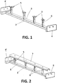
- the invention herein described consists of a chassis on which it is possible to sequentially or consecutively position all the elements of the structure to be assembled, on which chassis at least two templates will be arranged either as an additional element or as a part thereof, which templates comprise through holes on which laser equipment is assembled in order to mark or define the exact position of all the elements of the structure to be assembled thereon.
- Said chassis must be understood in the broadest sense thereof, as it could be formed by both an already assembled part of the structure on which other new elements are to be assembled and an independent frame on which the structure to be assembled is placed or fixed.
- chassis for the assembly of structures of an aircraft according to the present invention comprises:
- the beam emitted by the laser collimator goes through the through hole of its template and its complementary through hole in the other template until reaching the laser rangefinder, and where the coaxiality sensor can be placed at any point of the path of said beam for the purpose of providing the coordinates of said beam in an x and y plane.
- the function of the templates is to therefore serve as of guides for determining the positions of the laser equipment, where the position of the through holes of said templates is determined by the projection on same of the different axes in turn formed by the through holes present in each of the elements (ribs, actuators, etc.) which make up the structure to be assembled.
- the elements ribs, actuators, etc.
- the axes defined by the complementary through holes in each template constitute the passage of the laser beam which will serve to measure distances and coaxialities during the assembly of the different elements on the frame.
- a much more precise assembly will thereby be achieved than with the conventional systems used up until now, which consisted of using bolts or standard elements which, when introduced through the different through holes of the components, mechanically assured the coaxiality of said through holes with a tolerance typically around several tenths of a millimeter.
- said tolerance has been reduced by up to an order of magnitude, reaching hundredths of a millimeter, although it will depend in any case on the precision of the laser equipment and coaxiality sensor used.
- the templates are designed such that once the first element of the structure, for example a spar, is fixed on the chassis, the remaining elements forming said structure, such as ribs, skins, or coverings, etc., can be gradually fixed on same.
- the templates are designed such that they comprise the through holes required both in position and in number so that, based on said through holes and with the aid of the laser equipment, the different components can be assembled in the precise location and the relevant verifications can be performed once assembled.
- laser beams will be used for the assembly or construction of the structure using the through holes intended for that purpose, and on the other hand, other beams will be used to verify the correct position of the parts, the aerodynamic profile, etc., for which purpose through holes will be used, wherein the axis defined by these through holes follows the aerodynamic profile of the already assembled structure, i.e., wherein the laser beam passing through the complementary through holes of the two templates allows measuring the aerodynamic profile of the structure and thereby detecting surface deviations and corrugations.
- the so-called “datums” are obtained, which are references that are taken as a zero value or origin both of the chassis on which the assembly is performed and of the actual elements of the structure, based on the measurement of the jig of the invention, which will allow creating an X, Y, and Z coordinate-type reference system, such that the distances, dimensions, perpendicularity, coaxiality, parallelism, etc., between said components can be measured and referenced.
- the measurement and calibration thereof will be performed by means of the establishment of several reference points used to reference all the other points in space, thereby creating a position correction algorithm that subsequently allows correcting the relative positions of the different components of the structure as they are assembled on the chassis.
- This algorithm allows the method of the present invention to eliminate (for component assembly purposes) constructive errors, because once deviations between the different elements of the chassis and the deviation of the beam itself of the collimator with respect to the complementary through holes have been measured, these measurements are taken into account when applying the algorithm to calculate the position (coordinates) in which the different components of the structure must be situated.
- the present invention also relates to a method for the assembly of the structure of an aircraft based on the creation of the templates that are defined, arranged, integrated or assembled on the chassis which, as mentioned above, can be formed by a pre-assembled part of the structure or an independent frame. Therefore, once the templates for a given assembly have been designed and defined, said method comprises the following steps:
- the chassis on which the structure is assembled, and which therefore enables the application of the method of the invention is formed by a frame comprising:
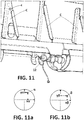
- Figure 10 shows a possible embodiment of a coaxiality sensor (12), i.e., a sensor to measure the position on a plane of the emitted laser beam or generated by the collimator (10) and which will be in charge of determining the degree of coaxiality of the different through holes (c) of the component elements of the structure, for example the ribs (C), in relation to said beam.
- a coaxiality sensor (12) i.e., a sensor to measure the position on a plane of the emitted laser beam or generated by the collimator (10) and which will be in charge of determining the degree of coaxiality of the different through holes (c) of the component elements of the structure, for example the ribs (C), in relation to said beam.
- said coaxiality sensor (12) will have an enclosure (13) for the necessary electronics, as well as respective hollow cylinders (14) which allow the laser beam to pass through to the detector situated therein, which cylinders are in turn intended for being coupled to the through holes present in each of the elements (ribs (C), actuators (8), etc.) making up the structure to be assembled in which coaxiality is to be measured.
- the use of sockets for the case in which cylinders (14) and through holes are different is envisaged.
- said coaxiality sensor (12) is placed in a first through hole of the structure, such as the one shown, for example, introducing its hollow cylinder, where once it has been positioned it will receive a laser beam that will mark a given point ⁇ with coordinates x ⁇ and y ⁇ in a manner similar to Figure 11a . Then the cylinder will be introduced in the other through hole of the structure which is located in the path defined by the laser beam, obtaining a point ⁇ defined by the coordinates x ⁇ and y ⁇ shown in Figure 11b . Based on those two positions, it will be possible to determine the deviation of one hole with respect to the other.
- the senor will have level, positioning and orientation marks with respect to the Earth's axis, such that when measuring coaxiality between two through holes, the sensor is always situated in the same position with respect to the beam for the purpose of preventing errors in the measurement.
- said coaxiality sensor not only provides information in that sense, but it also serves as a target surface so that the rangefinder (10) can determine the distance to said point.
- Figure 12 shows a schematic perspective view of the frame of the invention on which the assembly of the aileron (1) of the example has already been performed, and which can be seen completely assembled and removed from the frame in Figure 13 .
- the chassis can be formed by a part or portion of the structure itself, as in the case of the embodiment shown in Figure 19 , which shows the example of the assembly of an engine mount (16) on the section of wing (24) in which said engine is installed.
- the conventional solution is to use a jig which coordinates both products, limiting the infinite positions to just one.
- the use of the method of the invention is proposed as an alternative to the use of a conventional jig.
- the holes of the templates used for the passage of the laser beam are the bores (18, 18', 19, 19') situated or made solely for this task in the spars of the wing (17, 17'), which spars therefore act as templates (A and B). So the laser beam will be projected through these bores (18, 18', 19, 19') to subsequently apply the same method of assembly described in the present invention.
- the mount (16) is formed by a mechanically welded structure consisting of bars, brackets and two members (25, 25'). This structure will have two pick up points (22, 22', 23, 23') for the coaxiality sensor in each of the members (25, 25'), where each point of each member belongs to one of the two laser beams (21, 21').
- the present invention also relates to a method of assembly of the elements of an aircraft on a chassis, which can be formed by both an independent frame like the one described above and in Figures 1 to 12 and by a an already assembled part of the structure on which other new elements are to be assembled, as can be seen in Figure 19 .
Landscapes
- Engineering & Computer Science (AREA)
- Manufacturing & Machinery (AREA)
- Physics & Mathematics (AREA)
- Transportation (AREA)
- Aviation & Aerospace Engineering (AREA)
- Electromagnetism (AREA)
- General Physics & Mathematics (AREA)
- Radar, Positioning & Navigation (AREA)
- Remote Sensing (AREA)
- Length Measuring Devices By Optical Means (AREA)
Claims (12)
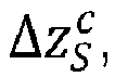
- Verfahren zur Montage der Struktur eines Flugzeugs, das Definieren mindestens einer ersten und einer zweiten Schablone (A, B) auf einem Chassis umfasst, so dass beide einander gegenüberliegen und parallel zueinander sind, wobei die Schablonen (A, B) eine Mehrzahl von Durchgangslöchern (a, b) aufweisen, so dass jedes der Durchgangslöcher der ersten Schablone einem komplementären Durchgangsloch in der zweiten Schablone entspricht; und wobei das Verfahren, nachdem die Schablonen definiert worden sind, die folgenden Schritte umfasst:1. Ausführung von einer Anfangsmessung des Chassis und der Schablonen (A, B), um die relativen Positionen im Verhältnis zueinander zu identifizieren und ihre tatsächliche Position im Raum zu kennen, wobei die Koordinaten der Punkte (ar, br) der Durchgangslöcher (a, b), die die "tatsächliche Achse" bilden, erhalten werden;2. Anordnung von Laserausrüstung auf zwei komplementären Durchgangslöchern von den Schablonen (A, B) zur Durchführung von Koaxialitäts- und Abstandsmessungen des Laserstrahls eines Kollimators (10), wobei die tatsächlichen "x"- und "z"-Koordinaten der Punkte (aL, bL) erhalten werden, die die Punkte sind, die der Laserstrahl durchläuft;3. Durchführung der Berechnung der mathematischen Gleichung H der Geraden des Laserstrahls des Kollimators, der (aL, bL) durchläuft, und dadurch Erhalten des Weges des Laserstrahls und somit der Zielpunkte der zu montierenden Elemente;4. Durchführung der mathematischen Berechnung der Koordinaten

 5. Durchführung der Berechnung der Zielmesswerte
 6. Positionierung des Elements (C) bis die von dem Koaxialitätssensor (12) und dem Entfernungsmesser (9) abgelesenen Werte mit den im vorherigen Schritt 5 berechneten Werten übereinstimmen;7. Befestigung des Elements an der zu montierenden Struktur mittels eines definitiven Befestigungstyps;8. Wiederholung der vorhergehenden Schritte 2 bis 7 für jedes Element, bis die Montage der Struktur abgeschlossen ist.
 - Verfahren zur Montage der Struktur eines Flugzeugs nach Anspruch 1, dadurch gekennzeichnet, dass um die tatsächlichen "x"- und "z"-Koordinaten der Punkte (aL, bL), die der Laserstrahl gemäß Schritt 2 durchläuft, zu erhalten:- der Kollimator (10) der Laserausrüstung so hinter der Schablone (B) angeordnet wird, dass der Laserstrahl zuerst ein Loch (b) der Platte und dann das komplementäre Loch (a) der anderen Schablone (A) durchläuft;- ein Koaxialitätssensor (12) in den Löchern (a, b) angeordnet wird, um die Abweichungen des Laserstrahls in Bezug auf die Messungen von Schritt 1 des Verfahrens zu messen;- die "x"- und "z"-Koordinaten der Punkte "aL" und "bL", die die Punkte des Kollimators (10) sind, durch die der Laserstrahl läuft, somit gemäß den folgenden mathematischen Ausdrücken erhalten werden:

 ∘ wobei
 ∘ wobei


 ∘ wobei
 ∘ wobei
 ∘ wobei
 - der Entfernungsmesser (9) der Laserausrüstung so hinter der Schablone (A) angeordnet ist, dass der Laserstrahl zuerst durch ein Loch (a) der Platte und dann durch das komplementäre Loch (b) der anderen Schablone (B) läuft;- ein Koaxialitätssensor (12) in den Löchern (a, b) angeordnet wird, um den relativen Abstand von ihnen zu dem Entfernungsmesser (9) zu messen; und- indem die Schablone A als Abstandsreferenz genommen wird, die y-Koordinaten der Punkte (aL, bL) gemäß den folgenden mathematischen Ausdrücken berechnet werden:
 ∘ wobei
 ∘ wobei
 ∘ wobei
 ∘ wobei
 ∘ wobei
- Verfahren zur Montage der Struktur eines Flugzeugs nach einem der vorstehenden Ansprüche, dadurch gekennzeichnet, dass unter Berücksichtigung, dass die "y"-Koordinaten für den Strahl des Entfernungsmessers (9) äquivalent zu den "y"-Koordinaten des Strahls des Kollimators (10) sind, um die tatsächlichen Koordinaten der Punkte (aL, bL), die der Laserstrahl gemäß Schritt 2 durchläuft, zu erhalten, die mathematische Gleichung der Geraden des Laserstrahls des Kollimators (10), d.h. die mathematische Gerade H, die durch (aL, bL) verläuft, wie folgt berechnet wird:


 ∘ wobei m und m' die Steigungen oder Neigungen der Geraden H in Bezug auf die YZ- bzw. XY-Ebene sind;∘ wobei n und n' die x- bzw. z-Koordinaten des Schnittpunktes der Geraden H mit der XZ-Ebene sind; und∘ wobei X, Y und Z die Koordinaten eines beliebigen Punktes sind, der zur Geraden H gehört.
 - Verfahren zur Montage der Struktur eines Flugzeugs nach einem der vorstehenden Ansprüche, dadurch gekennzeichnet, dass für die Berechnung der

 - der Koaxialitätssensor (12) so in Loch (c) angeordnet wird und das Element (C) so in einer Position im Raum angeordnet wird, dass der Laserstrahl des Kollimators den Koaxialitätssensor an einem Punkt namens "cL" oder Zielpunkt, wie folgt trifft:
 ∘ wobei
 ∘ wobei
 - für diesen Wert werden die Gleichungen der Geraden des Laserstrahls, um die x-, z-Koordinaten des Zielpunktes zu erhalten, wie folgt unterschieden:
 ∘ wobei

- Verfahren zur Montage der Struktur eines Flugzeugs nach einem der vorstehenden Ansprüche, dadurch gekennzeichnet, dass die Berechnung der Zielmesswerte


 ∘ wobei
 ∘ wobei
- System umfassend einen Rahmen und eine Laserausrüstung zur Montage der Struktur eines Flugzeugs unter Durchführung des Verfahrens nach Anspruch 1, wobei der Rahmen umfasst:- eine Basis (2) mit mindestens einem ersten und einem zweiten Ende (4, 4');- eine Vielzahl von Trägern (5), die an der Basis (2) befestigt sind und zwischen dem ersten und dem zweiten Ende (4, 4') platziert sind;- mindestens eine erste und eine zweite Schablone (A, B), die jeweils eine Innenseite und eine Außenseite aufweisen und mit ihrer Innenseite an dem ersten Ende (4) bzw. dem zweiten Ende (4') der Basis befestigt sind, so dass beide Schablonen (A, B) einander gegenüberliegen und parallel zueinander sind; und- wobei die Laserausrüstung umfasst:wobei die erste und die zweite Schablone (A, B) umfassen:∘ einen Kollimator (10) oder Strahlemitter;∘ einen Entfernungsmesser (9) oder eine Abstandsmessvorrichtung; und∘ einen Koaxialitätssensor (12)- eine Vielzahl von Durchgangslöchern (a, b), die einander gegenüberliegen, so dass jedes der Durchgangslöcher (a) der ersten Schablone (A) einem komplementären Durchgangsloch (b) in der zweiten Schablone (B) entspricht; und- einstellbare Befestigungsmittel, die auf den Außenseiten beider Platten platziert sind, um den Laserkollimator oder den Laserentfernungsmesser zu positionieren.
- System zur Montage eines Flugzeugs nach Anspruch 6, wobei die Schablonen (A, B) umfassen:- Durchgangslöcher (a1, b1), die den Laserstrahl platzieren, um das aerodynamische Profil der Struktur zu messen und/oder zu verifizieren;- Durchgangslöcher (a2, b2), die den Laserstrahl sowohl zur Montage des Bauteils, das die Position der Drehachse des Querruders definiert, als auch zur Verifizierung seiner Position platzieren;- Durchgangslöcher (a3, b3), die den Laserstrahl sowohl zur Montage der Aktuatoren (8) der Struktur als auch zur Verifizierung ihrer Position platzieren;- Durchgangslöcher (a4, b4), die den Laserstrahl zur Montage der Rippen (C) in Position platzieren.
- System zur Montage eines Flugzeugs nach einem der Ansprüche 6 oder 7, wobei es einstellbare Befestigungsmittel umfasst, die dazu bestimmt sind, den Entfernungsmesser (9) und den Kollimator (10) zu positionieren und ihre Position in Bezug auf die jeweiligen Durchgangslöcher (a, b) der Schablonen (A, B), die der Laserstrahl durchläuft, einzustellen.
- System zur Montage eines Flugzeugs nach einem der Ansprüche 6 bis 8, wobei der Koaxialitätssensor (12) ein Gehäuse (13) für die Elektronik sowie entsprechende Hohlzylinder (14) umfasst, die mit den Durchgangslöchern gekoppelt sein können, die in jedem der Elemente, aus denen die Struktur gebildet wird, vorhanden sind und die es dem Laserstrahl ermöglichen, die darin platzierten Detektor zu durchlaufen.
- System zur Montage eines Flugzeugs nach einem der Ansprüche 6 bis 9, wobei die Träger (5) Durchgangslöcher (6) umfassen, so dass der Durchgang eines Laserstrahls möglich ist, um Messungen auszuführen und/oder die Elemente der Struktur zu montieren.
- System zur Montage eines Flugzeugs nach Anspruch 6, wobei die Basis (2) durch zwei zueinander orthogonale Stäbe (3) mit bis zu vier Enden gebildet wird, an denen die entsprechenden Schablonen zu montieren sind.
- System zur Montage eines Flugzeugs nach Anspruch 6, wobei die Basis (2) durch vier Stäbe (3) gebildet wird, die so im Raum platziert sind, dass sie ein Viereck bilden, das die Schaffung eines Montagevolumens ermöglicht.
Priority Applications (3)
| Application Number | Priority Date | Filing Date | Title |
|---|---|---|---|
| EP18382127.1A EP3533716B1 (de) | 2018-03-01 | 2018-03-01 | Verfahren zur montage der struktur eines flugzeugs und rahmen zur durchführung des verfahrens |
| ES18382127T ES2859756T3 (es) | 2018-03-01 | 2018-03-01 | Procedimiento de montaje de la estructura de una aeronave y bastidor para llevar a cabo dicho procedimiento |
| US16/289,915 US11059604B2 (en) | 2018-03-01 | 2019-03-01 | Method of assembly of the structure of an aircraft and frame for carrying out said method |
Applications Claiming Priority (1)
| Application Number | Priority Date | Filing Date | Title |
|---|---|---|---|
| EP18382127.1A EP3533716B1 (de) | 2018-03-01 | 2018-03-01 | Verfahren zur montage der struktur eines flugzeugs und rahmen zur durchführung des verfahrens |
Publications (2)
| Publication Number | Publication Date |
|---|---|
| EP3533716A1 EP3533716A1 (de) | 2019-09-04 |
| EP3533716B1 true EP3533716B1 (de) | 2020-12-23 |
Family
ID=62063472
Family Applications (1)
| Application Number | Title | Priority Date | Filing Date |
|---|---|---|---|
| EP18382127.1A Active EP3533716B1 (de) | 2018-03-01 | 2018-03-01 | Verfahren zur montage der struktur eines flugzeugs und rahmen zur durchführung des verfahrens |
Country Status (3)
| Country | Link |
|---|---|
| US (1) | US11059604B2 (de) |
| EP (1) | EP3533716B1 (de) |
| ES (1) | ES2859756T3 (de) |
Families Citing this family (13)
| Publication number | Priority date | Publication date | Assignee | Title |
|---|---|---|---|---|
| ES2864734T3 (es) | 2018-10-31 | 2021-10-14 | Aciturri Eng S L U | Procedimiento de alineamiento de puntos duros en estructuras aeronáuticas |
| DE102020204993A1 (de) | 2020-04-21 | 2021-10-21 | Premium Aerotec Gmbh | Assistenzsystem und Verfahren zum Positionieren eines ersten Bauteils relativ zu einem zweiten Bauteil und Fernbedienung für ein Assistenzsystem |
| CN111907729A (zh) * | 2020-06-30 | 2020-11-10 | 成都飞机工业(集团)有限责任公司 | 一种针对飞机大部件调姿的最佳位姿拟合方法 |
| GB2599169A (en) * | 2020-09-29 | 2022-03-30 | Airbus Operations Ltd | A rigid temporary reinforcement structure |
| CN113460326B (zh) * | 2021-06-25 | 2023-07-21 | 成都飞机工业(集团)有限责任公司 | 一种机身立式装配主定位框变形计算及辅助控制方法 |
| CN113895646B (zh) * | 2021-10-26 | 2023-08-04 | 成都飞机工业(集团)有限责任公司 | 面向飞机部件调姿对接的自动测量方法及装置 |
| CN114954997B (zh) * | 2022-07-14 | 2022-12-13 | 成都飞机工业(集团)有限责任公司 | 一种舱门装配阶差的控制方法、装置、设备及介质 |
| CN115416871B (zh) * | 2022-08-17 | 2024-05-14 | 成都飞机工业(集团)有限责任公司 | 一种发动机推力销快速拆卸方法、装置、设备及介质 |
| CN115507790B (zh) * | 2022-10-16 | 2024-11-26 | 中国建筑第八工程局有限公司 | 一种基于非接触式的预制柱结构安装姿态检测装置 |
| CN116513476B (zh) * | 2023-04-21 | 2025-07-15 | 中航西安飞机工业集团股份有限公司 | 一种飞机盒段结构内部骨架肋的定位方法 |
| CN116443260B (zh) * | 2023-06-20 | 2023-09-19 | 中航西飞民用飞机有限责任公司 | 一种吊装式航空发动机入位安装方法 |
| CN116922333B (zh) * | 2023-08-10 | 2025-09-02 | 江西豪斯特汽车零部件有限公司 | 一种汽车零部件用对心装配装置及其装配方法 |
| CN120716960B (zh) * | 2025-08-25 | 2025-11-04 | 中航西安飞机工业集团股份有限公司 | 一种飞机上多耳片接头高精度定位安装测量调整方法 |
Family Cites Families (8)
| Publication number | Priority date | Publication date | Assignee | Title |
|---|---|---|---|---|
| US4937768A (en) * | 1987-04-14 | 1990-06-26 | Northrop Corporation | Integrated assembly system |
| US7509740B2 (en) * | 2001-11-13 | 2009-03-31 | The Boeing Company | Method of manufacturing a wing |
| GB9828473D0 (en) * | 1998-12-24 | 1999-02-17 | British Aerospace | Non-contact positioning apparatus |
| GB0008302D0 (en) * | 2000-04-06 | 2000-05-24 | British Aerospace | Assembly method |
| CN101460267A (zh) * | 2006-04-14 | 2009-06-17 | 基内西斯普公司 | 用于制造结构的方法和系统 |
| CN101746510B (zh) * | 2010-02-03 | 2012-12-19 | 北京航空航天大学 | 一种基于激光测量技术的前缘襟翼的装配方法 |
| US8903516B2 (en) | 2012-09-04 | 2014-12-02 | United Technologies Corporation | Visual alignment system and method for workpiece marking |
| WO2016142907A1 (en) * | 2015-03-12 | 2016-09-15 | Bombardier Inc. | Assembly of components with datum features |
-
2018
- 2018-03-01 ES ES18382127T patent/ES2859756T3/es active Active
- 2018-03-01 EP EP18382127.1A patent/EP3533716B1/de active Active
-
2019
- 2019-03-01 US US16/289,915 patent/US11059604B2/en active Active
Non-Patent Citations (1)
| Title |
|---|
| None * |
Also Published As
| Publication number | Publication date |
|---|---|
| US11059604B2 (en) | 2021-07-13 |
| ES2859756T3 (es) | 2021-10-04 |
| US20190270527A1 (en) | 2019-09-05 |
| EP3533716A1 (de) | 2019-09-04 |
Similar Documents
| Publication | Publication Date | Title |
|---|---|---|
| EP3533716B1 (de) | Verfahren zur montage der struktur eines flugzeugs und rahmen zur durchführung des verfahrens | |
| US11529706B2 (en) | Method of aligning hardpoints in aeronautical structures | |
| EP2276607B1 (de) | Verfahren und system zur erstellung der flugbahn eines luftfahrzeugs | |
| EP3814858B1 (de) | Verfahren und system zur herstellung von komponententeilen von flugzeugluftrahmen | |
| EP3134785B1 (de) | Flugzeugflugwerkanordnung | |
| EP3134782B1 (de) | Objektherstellung | |
| EP3587242A1 (de) | Verfahren und vorrichtung zur montage von flugzeugluftrahmen | |
| EP2937754A1 (de) | Flugzeugflugwerkanordnung | |
| AU2015250687B2 (en) | Assembly tool production | |
| EP3588219A1 (de) | Verfahren und vorrichtung zur herstellung von komponententeilen von flugzeugluftrahmen | |
| WO2015162402A2 (en) | Machining fixture production | |
| Palmateer | Optical Layup Template |
Legal Events
| Date | Code | Title | Description |
|---|---|---|---|
| PUAI | Public reference made under article 153(3) epc to a published international application that has entered the european phase |
Free format text: ORIGINAL CODE: 0009012 |
|
| STAA | Information on the status of an ep patent application or granted ep patent |
Free format text: STATUS: THE APPLICATION HAS BEEN PUBLISHED |
|
| AK | Designated contracting states |
Kind code of ref document: A1 Designated state(s): AL AT BE BG CH CY CZ DE DK EE ES FI FR GB GR HR HU IE IS IT LI LT LU LV MC MK MT NL NO PL PT RO RS SE SI SK SM TR |
|
| AX | Request for extension of the european patent |
Extension state: BA ME |
|
| STAA | Information on the status of an ep patent application or granted ep patent |
Free format text: STATUS: REQUEST FOR EXAMINATION WAS MADE |
|
| 17P | Request for examination filed |
Effective date: 20200219 |
|
| RBV | Designated contracting states (corrected) |
Designated state(s): AL AT BE BG CH CY CZ DE DK EE ES FI FR GB GR HR HU IE IS IT LI LT LU LV MC MK MT NL NO PL PT RO RS SE SI SK SM TR |
|
| GRAP | Despatch of communication of intention to grant a patent |
Free format text: ORIGINAL CODE: EPIDOSNIGR1 |
|
| STAA | Information on the status of an ep patent application or granted ep patent |
Free format text: STATUS: GRANT OF PATENT IS INTENDED |
|
| INTG | Intention to grant announced |
Effective date: 20200722 |
|
| GRAS | Grant fee paid |
Free format text: ORIGINAL CODE: EPIDOSNIGR3 |
|
| GRAA | (expected) grant |
Free format text: ORIGINAL CODE: 0009210 |
|
| STAA | Information on the status of an ep patent application or granted ep patent |
Free format text: STATUS: THE PATENT HAS BEEN GRANTED |
|
| AK | Designated contracting states |
Kind code of ref document: B1 Designated state(s): AL AT BE BG CH CY CZ DE DK EE ES FI FR GB GR HR HU IE IS IT LI LT LU LV MC MK MT NL NO PL PT RO RS SE SI SK SM TR |
|
| REG | Reference to a national code |
Ref country code: GB Ref legal event code: FG4D |
|
| REG | Reference to a national code |
Ref country code: DE Ref legal event code: R096 Ref document number: 602018011090 Country of ref document: DE |
|
| REG | Reference to a national code |
Ref country code: AT Ref legal event code: REF Ref document number: 1347468 Country of ref document: AT Kind code of ref document: T Effective date: 20210115 |
|
| REG | Reference to a national code |
Ref country code: IE Ref legal event code: FG4D |
|
| PG25 | Lapsed in a contracting state [announced via postgrant information from national office to epo] |
Ref country code: FI Free format text: LAPSE BECAUSE OF FAILURE TO SUBMIT A TRANSLATION OF THE DESCRIPTION OR TO PAY THE FEE WITHIN THE PRESCRIBED TIME-LIMIT Effective date: 20201223 Ref country code: RS Free format text: LAPSE BECAUSE OF FAILURE TO SUBMIT A TRANSLATION OF THE DESCRIPTION OR TO PAY THE FEE WITHIN THE PRESCRIBED TIME-LIMIT Effective date: 20201223 Ref country code: NO Free format text: LAPSE BECAUSE OF FAILURE TO SUBMIT A TRANSLATION OF THE DESCRIPTION OR TO PAY THE FEE WITHIN THE PRESCRIBED TIME-LIMIT Effective date: 20210323 Ref country code: GR Free format text: LAPSE BECAUSE OF FAILURE TO SUBMIT A TRANSLATION OF THE DESCRIPTION OR TO PAY THE FEE WITHIN THE PRESCRIBED TIME-LIMIT Effective date: 20210324 |
|
| REG | Reference to a national code |
Ref country code: AT Ref legal event code: MK05 Ref document number: 1347468 Country of ref document: AT Kind code of ref document: T Effective date: 20201223 |
|
| REG | Reference to a national code |
Ref country code: NL Ref legal event code: MP Effective date: 20201223 |
|
| PG25 | Lapsed in a contracting state [announced via postgrant information from national office to epo] |
Ref country code: BG Free format text: LAPSE BECAUSE OF FAILURE TO SUBMIT A TRANSLATION OF THE DESCRIPTION OR TO PAY THE FEE WITHIN THE PRESCRIBED TIME-LIMIT Effective date: 20210323 Ref country code: SE Free format text: LAPSE BECAUSE OF FAILURE TO SUBMIT A TRANSLATION OF THE DESCRIPTION OR TO PAY THE FEE WITHIN THE PRESCRIBED TIME-LIMIT Effective date: 20201223 Ref country code: LV Free format text: LAPSE BECAUSE OF FAILURE TO SUBMIT A TRANSLATION OF THE DESCRIPTION OR TO PAY THE FEE WITHIN THE PRESCRIBED TIME-LIMIT Effective date: 20201223 |
|
| PG25 | Lapsed in a contracting state [announced via postgrant information from national office to epo] |
Ref country code: NL Free format text: LAPSE BECAUSE OF FAILURE TO SUBMIT A TRANSLATION OF THE DESCRIPTION OR TO PAY THE FEE WITHIN THE PRESCRIBED TIME-LIMIT Effective date: 20201223 Ref country code: HR Free format text: LAPSE BECAUSE OF FAILURE TO SUBMIT A TRANSLATION OF THE DESCRIPTION OR TO PAY THE FEE WITHIN THE PRESCRIBED TIME-LIMIT Effective date: 20201223 |
|
| REG | Reference to a national code |
Ref country code: LT Ref legal event code: MG9D |
|
| PG25 | Lapsed in a contracting state [announced via postgrant information from national office to epo] |
Ref country code: CZ Free format text: LAPSE BECAUSE OF FAILURE TO SUBMIT A TRANSLATION OF THE DESCRIPTION OR TO PAY THE FEE WITHIN THE PRESCRIBED TIME-LIMIT Effective date: 20201223 Ref country code: EE Free format text: LAPSE BECAUSE OF FAILURE TO SUBMIT A TRANSLATION OF THE DESCRIPTION OR TO PAY THE FEE WITHIN THE PRESCRIBED TIME-LIMIT Effective date: 20201223 Ref country code: SK Free format text: LAPSE BECAUSE OF FAILURE TO SUBMIT A TRANSLATION OF THE DESCRIPTION OR TO PAY THE FEE WITHIN THE PRESCRIBED TIME-LIMIT Effective date: 20201223 Ref country code: SM Free format text: LAPSE BECAUSE OF FAILURE TO SUBMIT A TRANSLATION OF THE DESCRIPTION OR TO PAY THE FEE WITHIN THE PRESCRIBED TIME-LIMIT Effective date: 20201223 Ref country code: RO Free format text: LAPSE BECAUSE OF FAILURE TO SUBMIT A TRANSLATION OF THE DESCRIPTION OR TO PAY THE FEE WITHIN THE PRESCRIBED TIME-LIMIT Effective date: 20201223 Ref country code: PT Free format text: LAPSE BECAUSE OF FAILURE TO SUBMIT A TRANSLATION OF THE DESCRIPTION OR TO PAY THE FEE WITHIN THE PRESCRIBED TIME-LIMIT Effective date: 20210423 Ref country code: LT Free format text: LAPSE BECAUSE OF FAILURE TO SUBMIT A TRANSLATION OF THE DESCRIPTION OR TO PAY THE FEE WITHIN THE PRESCRIBED TIME-LIMIT Effective date: 20201223 |
|
| PG25 | Lapsed in a contracting state [announced via postgrant information from national office to epo] |
Ref country code: AT Free format text: LAPSE BECAUSE OF FAILURE TO SUBMIT A TRANSLATION OF THE DESCRIPTION OR TO PAY THE FEE WITHIN THE PRESCRIBED TIME-LIMIT Effective date: 20201223 Ref country code: PL Free format text: LAPSE BECAUSE OF FAILURE TO SUBMIT A TRANSLATION OF THE DESCRIPTION OR TO PAY THE FEE WITHIN THE PRESCRIBED TIME-LIMIT Effective date: 20201223 |
|
| REG | Reference to a national code |
Ref country code: DE Ref legal event code: R097 Ref document number: 602018011090 Country of ref document: DE |
|
| PG25 | Lapsed in a contracting state [announced via postgrant information from national office to epo] |
Ref country code: IS Free format text: LAPSE BECAUSE OF FAILURE TO SUBMIT A TRANSLATION OF THE DESCRIPTION OR TO PAY THE FEE WITHIN THE PRESCRIBED TIME-LIMIT Effective date: 20210423 |
|
| REG | Reference to a national code |
Ref country code: ES Ref legal event code: FG2A Ref document number: 2859756 Country of ref document: ES Kind code of ref document: T3 Effective date: 20211004 |
|
| PG25 | Lapsed in a contracting state [announced via postgrant information from national office to epo] |
Ref country code: MC Free format text: LAPSE BECAUSE OF FAILURE TO SUBMIT A TRANSLATION OF THE DESCRIPTION OR TO PAY THE FEE WITHIN THE PRESCRIBED TIME-LIMIT Effective date: 20201223 Ref country code: AL Free format text: LAPSE BECAUSE OF FAILURE TO SUBMIT A TRANSLATION OF THE DESCRIPTION OR TO PAY THE FEE WITHIN THE PRESCRIBED TIME-LIMIT Effective date: 20201223 |
|
| PLBE | No opposition filed within time limit |
Free format text: ORIGINAL CODE: 0009261 |
|
| REG | Reference to a national code |
Ref country code: CH Ref legal event code: PL |
|
| STAA | Information on the status of an ep patent application or granted ep patent |
Free format text: STATUS: NO OPPOSITION FILED WITHIN TIME LIMIT |
|
| PG25 | Lapsed in a contracting state [announced via postgrant information from national office to epo] |
Ref country code: DK Free format text: LAPSE BECAUSE OF FAILURE TO SUBMIT A TRANSLATION OF THE DESCRIPTION OR TO PAY THE FEE WITHIN THE PRESCRIBED TIME-LIMIT Effective date: 20201223 |
|
| 26N | No opposition filed |
Effective date: 20210924 |
|
| REG | Reference to a national code |
Ref country code: BE Ref legal event code: MM Effective date: 20210331 |
|
| PG25 | Lapsed in a contracting state [announced via postgrant information from national office to epo] |
Ref country code: CH Free format text: LAPSE BECAUSE OF NON-PAYMENT OF DUE FEES Effective date: 20210331 Ref country code: LI Free format text: LAPSE BECAUSE OF NON-PAYMENT OF DUE FEES Effective date: 20210331 Ref country code: IE Free format text: LAPSE BECAUSE OF NON-PAYMENT OF DUE FEES Effective date: 20210301 Ref country code: LU Free format text: LAPSE BECAUSE OF NON-PAYMENT OF DUE FEES Effective date: 20210301 |
|
| PG25 | Lapsed in a contracting state [announced via postgrant information from national office to epo] |
Ref country code: SI Free format text: LAPSE BECAUSE OF FAILURE TO SUBMIT A TRANSLATION OF THE DESCRIPTION OR TO PAY THE FEE WITHIN THE PRESCRIBED TIME-LIMIT Effective date: 20201223 |
|
| PG25 | Lapsed in a contracting state [announced via postgrant information from national office to epo] |
Ref country code: IS Free format text: LAPSE BECAUSE OF FAILURE TO SUBMIT A TRANSLATION OF THE DESCRIPTION OR TO PAY THE FEE WITHIN THE PRESCRIBED TIME-LIMIT Effective date: 20210423 |
|
| PG25 | Lapsed in a contracting state [announced via postgrant information from national office to epo] |
Ref country code: BE Free format text: LAPSE BECAUSE OF NON-PAYMENT OF DUE FEES Effective date: 20210331 |
|
| PG25 | Lapsed in a contracting state [announced via postgrant information from national office to epo] |
Ref country code: CY Free format text: LAPSE BECAUSE OF FAILURE TO SUBMIT A TRANSLATION OF THE DESCRIPTION OR TO PAY THE FEE WITHIN THE PRESCRIBED TIME-LIMIT Effective date: 20201223 |
|
| P01 | Opt-out of the competence of the unified patent court (upc) registered |
Effective date: 20230529 |
|
| PG25 | Lapsed in a contracting state [announced via postgrant information from national office to epo] |
Ref country code: HU Free format text: LAPSE BECAUSE OF FAILURE TO SUBMIT A TRANSLATION OF THE DESCRIPTION OR TO PAY THE FEE WITHIN THE PRESCRIBED TIME-LIMIT; INVALID AB INITIO Effective date: 20180301 |
|
| PG25 | Lapsed in a contracting state [announced via postgrant information from national office to epo] |
Ref country code: MK Free format text: LAPSE BECAUSE OF FAILURE TO SUBMIT A TRANSLATION OF THE DESCRIPTION OR TO PAY THE FEE WITHIN THE PRESCRIBED TIME-LIMIT Effective date: 20201223 |
|
| PG25 | Lapsed in a contracting state [announced via postgrant information from national office to epo] |
Ref country code: TR Free format text: LAPSE BECAUSE OF FAILURE TO SUBMIT A TRANSLATION OF THE DESCRIPTION OR TO PAY THE FEE WITHIN THE PRESCRIBED TIME-LIMIT Effective date: 20201223 |
|
| PG25 | Lapsed in a contracting state [announced via postgrant information from national office to epo] |
Ref country code: MT Free format text: LAPSE BECAUSE OF FAILURE TO SUBMIT A TRANSLATION OF THE DESCRIPTION OR TO PAY THE FEE WITHIN THE PRESCRIBED TIME-LIMIT Effective date: 20201223 |
|
| PGFP | Annual fee paid to national office [announced via postgrant information from national office to epo] |
Ref country code: ES Payment date: 20250401 Year of fee payment: 8 |
|
| PGFP | Annual fee paid to national office [announced via postgrant information from national office to epo] |
Ref country code: GB Payment date: 20260309 Year of fee payment: 9 |
|
| PGFP | Annual fee paid to national office [announced via postgrant information from national office to epo] |
Ref country code: DE Payment date: 20260319 Year of fee payment: 9 |
|
| PGFP | Annual fee paid to national office [announced via postgrant information from national office to epo] |
Ref country code: IT Payment date: 20260324 Year of fee payment: 9 |
|
| PGFP | Annual fee paid to national office [announced via postgrant information from national office to epo] |
Ref country code: FR Payment date: 20260309 Year of fee payment: 9 |