EP3533658B1 - Ladestation und ladesystem für elektromobile - Google Patents
Ladestation und ladesystem für elektromobile Download PDFInfo
- Publication number
- EP3533658B1 EP3533658B1 EP18159787.3A EP18159787A EP3533658B1 EP 3533658 B1 EP3533658 B1 EP 3533658B1 EP 18159787 A EP18159787 A EP 18159787A EP 3533658 B1 EP3533658 B1 EP 3533658B1
- Authority
- EP
- European Patent Office
- Prior art keywords
- charging
- voltage
- unit
- charging station
- alternating current
- Prior art date
- Legal status (The legal status is an assumption and is not a legal conclusion. Google has not performed a legal analysis and makes no representation as to the accuracy of the status listed.)
- Active
Links
Images


Classifications
-
- B—PERFORMING OPERATIONS; TRANSPORTING
- B60—VEHICLES IN GENERAL
- B60L—PROPULSION OF ELECTRICALLY-PROPELLED VEHICLES; SUPPLYING ELECTRIC POWER FOR AUXILIARY EQUIPMENT OF ELECTRICALLY-PROPELLED VEHICLES; ELECTRODYNAMIC BRAKE SYSTEMS FOR VEHICLES IN GENERAL; MAGNETIC SUSPENSION OR LEVITATION FOR VEHICLES; MONITORING OPERATING VARIABLES OF ELECTRICALLY-PROPELLED VEHICLES; ELECTRIC SAFETY DEVICES FOR ELECTRICALLY-PROPELLED VEHICLES
- B60L53/00—Methods of charging batteries, specially adapted for electric vehicles; Charging stations or on-board charging equipment therefor; Exchange of energy storage elements in electric vehicles
- B60L53/20—Methods of charging batteries, specially adapted for electric vehicles; Charging stations or on-board charging equipment therefor; Exchange of energy storage elements in electric vehicles characterised by converters located in the vehicle
- B60L53/22—Constructional details or arrangements of charging converters specially adapted for charging electric vehicles
-
- B—PERFORMING OPERATIONS; TRANSPORTING
- B60—VEHICLES IN GENERAL
- B60L—PROPULSION OF ELECTRICALLY-PROPELLED VEHICLES; SUPPLYING ELECTRIC POWER FOR AUXILIARY EQUIPMENT OF ELECTRICALLY-PROPELLED VEHICLES; ELECTRODYNAMIC BRAKE SYSTEMS FOR VEHICLES IN GENERAL; MAGNETIC SUSPENSION OR LEVITATION FOR VEHICLES; MONITORING OPERATING VARIABLES OF ELECTRICALLY-PROPELLED VEHICLES; ELECTRIC SAFETY DEVICES FOR ELECTRICALLY-PROPELLED VEHICLES
- B60L53/00—Methods of charging batteries, specially adapted for electric vehicles; Charging stations or on-board charging equipment therefor; Exchange of energy storage elements in electric vehicles
- B60L53/30—Constructional details of charging stations
-
- B—PERFORMING OPERATIONS; TRANSPORTING
- B60—VEHICLES IN GENERAL
- B60L—PROPULSION OF ELECTRICALLY-PROPELLED VEHICLES; SUPPLYING ELECTRIC POWER FOR AUXILIARY EQUIPMENT OF ELECTRICALLY-PROPELLED VEHICLES; ELECTRODYNAMIC BRAKE SYSTEMS FOR VEHICLES IN GENERAL; MAGNETIC SUSPENSION OR LEVITATION FOR VEHICLES; MONITORING OPERATING VARIABLES OF ELECTRICALLY-PROPELLED VEHICLES; ELECTRIC SAFETY DEVICES FOR ELECTRICALLY-PROPELLED VEHICLES
- B60L53/00—Methods of charging batteries, specially adapted for electric vehicles; Charging stations or on-board charging equipment therefor; Exchange of energy storage elements in electric vehicles
- B60L53/30—Constructional details of charging stations
- B60L53/31—Charging columns specially adapted for electric vehicles
-
- H—ELECTRICITY
- H02—GENERATION; CONVERSION OR DISTRIBUTION OF ELECTRIC POWER
- H02J—ELECTRIC POWER NETWORKS; CIRCUIT ARRANGEMENTS OR SYSTEMS FOR SUPPLYING OR DISTRIBUTING ELECTRIC POWER; SYSTEMS FOR STORING ELECTRIC ENERGY
- H02J3/00—Circuit arrangements for AC mains or AC distribution networks
- H02J3/28—Arrangements for balancing of the load in networks by storage of energy
- H02J3/32—Arrangements for balancing of the load in networks by storage of energy using batteries or super capacitors with converting means
- H02J3/322—Arrangements for balancing of the load in networks by storage of energy using batteries or super capacitors with converting means the battery being on-board an electric or hybrid vehicle, e.g. vehicle to grid arrangements [V2G], power aggregation, use of the battery for network load balancing, coordinated or cooperative battery charging
-
- H—ELECTRICITY
- H02—GENERATION; CONVERSION OR DISTRIBUTION OF ELECTRIC POWER
- H02J—ELECTRIC POWER NETWORKS; CIRCUIT ARRANGEMENTS OR SYSTEMS FOR SUPPLYING OR DISTRIBUTING ELECTRIC POWER; SYSTEMS FOR STORING ELECTRIC ENERGY
- H02J7/00—Circuit arrangements for charging or discharging batteries or for supplying loads from batteries
- H02J7/70—Circuit arrangements for charging or discharging batteries or for supplying loads from batteries characterised by the mechanical construction
-
- H—ELECTRICITY
- H02—GENERATION; CONVERSION OR DISTRIBUTION OF ELECTRIC POWER
- H02J—ELECTRIC POWER NETWORKS; CIRCUIT ARRANGEMENTS OR SYSTEMS FOR SUPPLYING OR DISTRIBUTING ELECTRIC POWER; SYSTEMS FOR STORING ELECTRIC ENERGY
- H02J2105/00—Networks for supplying or distributing electric power characterised by their spatial reach or by the load
- H02J2105/30—Networks for supplying or distributing electric power characterised by their spatial reach or by the load the load networks being external to vehicles, i.e. exchanging power with vehicles
- H02J2105/33—Networks for supplying or distributing electric power characterised by their spatial reach or by the load the load networks being external to vehicles, i.e. exchanging power with vehicles exchanging power with road vehicles
- H02J2105/37—Networks for supplying or distributing electric power characterised by their spatial reach or by the load the load networks being external to vehicles, i.e. exchanging power with vehicles exchanging power with road vehicles exchanging power with electric vehicles [EV] or with hybrid electric vehicles [HEV]
-
- Y—GENERAL TAGGING OF NEW TECHNOLOGICAL DEVELOPMENTS; GENERAL TAGGING OF CROSS-SECTIONAL TECHNOLOGIES SPANNING OVER SEVERAL SECTIONS OF THE IPC; TECHNICAL SUBJECTS COVERED BY FORMER USPC CROSS-REFERENCE ART COLLECTIONS [XRACs] AND DIGESTS
- Y02—TECHNOLOGIES OR APPLICATIONS FOR MITIGATION OR ADAPTATION AGAINST CLIMATE CHANGE
- Y02T—CLIMATE CHANGE MITIGATION TECHNOLOGIES RELATED TO TRANSPORTATION
- Y02T10/00—Road transport of goods or passengers
- Y02T10/60—Other road transportation technologies with climate change mitigation effect
- Y02T10/70—Energy storage systems for electromobility, e.g. batteries
-
- Y—GENERAL TAGGING OF NEW TECHNOLOGICAL DEVELOPMENTS; GENERAL TAGGING OF CROSS-SECTIONAL TECHNOLOGIES SPANNING OVER SEVERAL SECTIONS OF THE IPC; TECHNICAL SUBJECTS COVERED BY FORMER USPC CROSS-REFERENCE ART COLLECTIONS [XRACs] AND DIGESTS
- Y02—TECHNOLOGIES OR APPLICATIONS FOR MITIGATION OR ADAPTATION AGAINST CLIMATE CHANGE
- Y02T—CLIMATE CHANGE MITIGATION TECHNOLOGIES RELATED TO TRANSPORTATION
- Y02T10/00—Road transport of goods or passengers
- Y02T10/60—Other road transportation technologies with climate change mitigation effect
- Y02T10/7072—Electromobility specific charging systems or methods for batteries, ultracapacitors, supercapacitors or double-layer capacitors
-
- Y—GENERAL TAGGING OF NEW TECHNOLOGICAL DEVELOPMENTS; GENERAL TAGGING OF CROSS-SECTIONAL TECHNOLOGIES SPANNING OVER SEVERAL SECTIONS OF THE IPC; TECHNICAL SUBJECTS COVERED BY FORMER USPC CROSS-REFERENCE ART COLLECTIONS [XRACs] AND DIGESTS
- Y02—TECHNOLOGIES OR APPLICATIONS FOR MITIGATION OR ADAPTATION AGAINST CLIMATE CHANGE
- Y02T—CLIMATE CHANGE MITIGATION TECHNOLOGIES RELATED TO TRANSPORTATION
- Y02T90/00—Enabling technologies or technologies with a potential or indirect contribution to GHG emissions mitigation
- Y02T90/10—Technologies relating to charging of electric vehicles
- Y02T90/12—Electric charging stations
-
- Y—GENERAL TAGGING OF NEW TECHNOLOGICAL DEVELOPMENTS; GENERAL TAGGING OF CROSS-SECTIONAL TECHNOLOGIES SPANNING OVER SEVERAL SECTIONS OF THE IPC; TECHNICAL SUBJECTS COVERED BY FORMER USPC CROSS-REFERENCE ART COLLECTIONS [XRACs] AND DIGESTS
- Y02—TECHNOLOGIES OR APPLICATIONS FOR MITIGATION OR ADAPTATION AGAINST CLIMATE CHANGE
- Y02T—CLIMATE CHANGE MITIGATION TECHNOLOGIES RELATED TO TRANSPORTATION
- Y02T90/00—Enabling technologies or technologies with a potential or indirect contribution to GHG emissions mitigation
- Y02T90/10—Technologies relating to charging of electric vehicles
- Y02T90/14—Plug-in electric vehicles
Definitions
- the present invention relates to a charging station and a system and a method for charging a battery of an electric vehicle.
- electromobility requires the provision of a corresponding charging infrastructure for charging electromobiles such as electric cars, electric trucks or electric two-wheelers.
- Corresponding charging stations are designed, for example, as charging columns or also as wall charging stations (wall boxes). The charging stations provide the electrical power required to charge the batteries. Electric vehicles can usually be parked in the vicinity of the charging station and connected for the duration of the charging process.
- the charging stations can provide alternating current (AC) or direct current (DC).
- the actual battery charging process normally requires the application of a DC voltage to the battery.
- the charging station is designed as a direct current charging station, a further conversion can possibly be dispensed with and the voltage provided can be applied directly to the battery.
- the charger is integrated into the charging station, so to speak. Vehicles that are charged with alternating current have a charger built into the vehicle that converts the alternating current into Converts direct current.
- the advantage of AC charging is that AC power is available in most households and elsewhere. No further conversion is therefore necessary.
- the often lower achievable charging power is a disadvantage.
- Modern fast charging systems are mostly based on direct current charging at high voltage, for example 400 or 800 V. With such voltages, charging powers in the range of 50 kW can be achieved, so that an electric vehicle can be charged in a period of approximately one hour. The achievable performance with AC charging stations is often much lower.
- a medium voltage e.g. 10, 20 or 30 kV
- a low voltage e.g. 230, 400 or 1,000 V
- the low voltage is then distributed via a corresponding distribution network.
- Both connected end consumers and connected charging stations are supplied by the low-voltage distribution network.
- a challenge for the network operator is that with an increasing number of charging stations that are connected to a single low-voltage cable harness, the utilization of this cable harness can increase sharply.
- the voltage drop on the cable harness also increases.
- high power is required to charge connected electric vehicles. Therefore, only a certain number of charging stations can be provided per cable strand. If further charging stations are then required, another cable harness must be laid.
- the current flow in the low-voltage network is usually limited to 250 A or 315 A per cable strand.
- transformers are often used in distribution stations. In typical planning approaches, such a transformer would be overloaded if 300 residential units, 80 percent of which have an electric car, are connected. Problematic about the The use of larger transformers is the need for space and space, which increases with increasing power and which often cannot be met in the existing infrastructure and permitted buildings.
- DE 10 2016 102 053 A1 discloses a circuit system for a charging station, a charging station and a use of a charging station.
- the circuit system is provided for charging an energy store in a vehicle.
- the circuit system comprises a transformer with transformer outputs that are galvanically isolated from one another.
- a first subsystem and a second subsystem are each connected to one of the transformer outputs.
- the first subsystem and the second subsystem each include a rectifier which is connected upstream of a DC voltage converter.
- the DC / DC converter is coupled to a switching logic on its input side or on its output side.
- the first subsystem is connected to a delta connection in the transformer output and the second subsystem is connected to a star connection in the transformer output.
- the US 2013/0020993 A1 relates to a multi-mode charging station for electric vehicles.
- a scaled-down and simplified multi-mode electric vehicle charging station is provided that allows a user to choose between AC and DC output.
- a DC converter is connected to a voltage source, which then outputs to a DC bus or to an electrical connection.
- the DC bus can be used by DC charging equipment or a DC-AC inverter connected to AC charging equipment, providing both DC and AC charging options.
- the US 2011/0055037 A1 relates to a charging system that can be connected to an energy source.
- the DE 10 2015 110 023 A1 relates to a charging station and a method for charging a plug-in motor vehicle at a charging station.
- the charging station includes a power transformer and rectifier modules.
- the performance The transformer has galvanically separated conductors on the secondary side.
- the leads are at least partially connected to the rectifier modules.
- the power transformer and the rectifier modules are configured in such a way that the rectifier modules output a low DC voltage when the power transformer is fed with a medium voltage.
- the EP 2 185 913 A1 relates to a charging system for electric vehicles.
- the charging system comprises an input section for connection to an AC voltage network and an output section for connection to an electric vehicle. Furthermore, the charging system comprises a conversion section for converting an alternating voltage into a direct voltage and a control unit which is designed to control the conversion section.
- the present invention has the task of enabling the batteries of electric vehicles to be charged efficiently, taking into account the current power grid infrastructure.
- security of supply should be guaranteed even with the foreseeable further spread of electromobility; on the other hand, the necessary adjustments to the network infrastructure and costs should be kept to a minimum.
- the charging station is connected directly to a section (or part) of the medium-voltage network and draws an AC input voltage from this medium-voltage network.
- the medium voltage network is preferably a 6, 10, 20 or 30 kV network to which otherwise only transformer stations are usually connected, which transform the medium voltage into a low voltage in order to supply end users.
- the network connection unit of the charging station according to the invention is designed for direct connection to the higher voltages.
- the network connection unit preferably has the necessary safety and isolation devices.
- the AC input voltage is then converted in the transformer unit, on the one hand, into an AC charging voltage and, on the other hand, into a DC charging voltage.
- the voltage is preferably reduced based on the incoming higher voltage of the medium-voltage network, for example to 400 or 800 V.
- the two charging voltages generated can then be provided via the charging unit in order to enable the battery of the electric vehicle to be charged.
- the term coupling in this context is to be understood as a releasable connection, the charging unit preferably comprising a corresponding plug and a cable that can be connected to the electric vehicle (corresponds in this case to a so-called plug-in electric vehicle).
- the charging unit can also be designed in a different way, for example for inductive charging or for charging a module (replaceable battery) that can be removed from an electric vehicle.
- electromobile is understood here in particular to mean all types of fully and partially electrically (hybrid-electric) driven vehicles with a chargeable energy store (battery), for example electric cars, electric trucks or electric two-wheelers.
- a chargeable energy store for example electric cars, electric trucks or electric two-wheelers.
- the system according to the invention also comprises a section of a medium-voltage network to which the charging station is connected.
- the charging station according to the invention is connected directly to the medium-voltage network.
- a transformation of the medium voltage into the required charging voltage takes place within the column. This means that the comparatively high power required for the charging process can be made available without the network being overloaded by large currents. It is avoided that previous substations for transforming the medium voltage into the low voltage are overloaded. It is no longer necessary to provide larger transformers with high power reserves. Because a medium-voltage cable can transport significantly more energy than a low-voltage cable due to the higher voltage, the possible number of charging stations that can be connected per cable strand is very large.
- the invention represents a decentralized approach in which it is not necessary to first take the intermediate step via the low-voltage network.
- the space requirement is shifted to the installation area or reduced.
- Adaptation of the existing infrastructure is largely avoided, so that costs can be saved.
- the charging station according to the invention enables flexible applicability through the simultaneous provision of an alternating current charging voltage and a direct current charging voltage.
- An electric vehicle can be connected and charged, regardless of whether an electric vehicle is to be supplied with or without an integrated charger.
- the transformer unit is designed as a solid state transformer, SST.
- SST allows simultaneous Generation of an alternating voltage and a direct voltage. Due to the way it works, a solid-state transformer requires less floor space than a conventional two- or three-winding transformer with the same transmission capacity. In addition, the implementation can be carried out much more cheaply.
- an SST enables an AC charging voltage and a DC charging voltage to be provided at the same time. It is possible to feed the SST with high voltage (medium voltage). A scalable integration of charging stations into existing networks can be ensured.
- the transformer unit preferably comprises a transmission unit for carrying out a medium-frequency transmission for voltage transformation, preferably at a frequency between 100 Hz and 50 kHz.
- a transmission transformation
- the incoming AC input voltage (medium voltage) can be transformed into a (preferably lower) charging voltage.
- the voltage transformation is preferably carried out at a frequency between 100 Hz and 50 kHz. Frequencies in the range of several kHz are usually used. At such high frequencies, high powers can be transmitted with little space requirement. With a comparable output, the same transformer or transmitter is much smaller. This means that the transformer unit can be integrated into a charging station or into a wall charging station. There is no need for an external transformer between the voltage of the medium-voltage network and the voltage of the low-voltage network.
- the transformer unit comprises a primary-side power electronics unit which is designed to carry out rectification and frequency adjustment of the AC input voltage.
- a primary-side power electronics unit which is designed to carry out rectification and frequency adjustment of the AC input voltage.
- an input-side (primary-side) power electronics are provided, which allow an adaptation of the frequency and a rectification.
- the frequency is increased.
- the incoming AC input voltage has a frequency of 50 Hz.
- the frequency of the The voltage generated by power electronics on the input side has a much higher frequency of, for example, a few kHz. Corresponding rectification and frequency adjustment can be carried out by using power electronics.
- the transformer unit comprises a secondary-side power electronics unit which is designed to carry out a frequency adjustment in order to generate the direct current charging voltage; and perform frequency adjustment and inversion to generate the AC charging voltage.
- the frequency is adjusted again in order to generate a charging voltage.
- the DC charging voltage requires that a frequency be adjusted.
- An alternation must also be carried out for the alternating current charging voltage.
- the AC input voltage is advantageously a voltage between 1 kV and 52 kV, preferably between 10 kV and 30 kV; and / or the AC charging voltage and / or the DC charging voltage is a voltage between 200 V and 1000 V, preferably between 350 V and 450 V.
- Conventional medium-voltage networks are operated at 10, 20 or 30 kV.
- Modern electric cars are often charged at voltages of 400 or 800 V. By using higher voltages, the currents can also be limited at higher powers. The use of thick cables is not necessary.
- the charging station is designed as a free-standing charging column.
- Such free-standing charging stations can be used, for example, in public traffic areas or also in parking lots or in underground garages. Fast charging can be achieved through a medium-voltage mains connection.
- the charging station comprises a measuring unit for determining a consumption value that corresponds to that obtained from the electric vehicle Describes charging energy.
- the measuring unit allows the charging energy transferred to the electric vehicle to be measured. This enables the charging power used to be invoiced to the network operator or to the provider of the charging station.
- the measuring unit preferably comprises an ammeter.
- the charging station comprises a load control unit for determining a charging power provided.
- a load control unit for determining a charging power provided.
- the additional use of a load control unit can, in particular, limit the power provided. It is made possible for a central instance to intervene in a regulating and / or controlling manner in order to prevent overloading of the networks. For example, if a large number of electric vehicles are to be charged at the same time, an overload can occur.
- a load control unit allows, so to speak, a throttling of the power provided at a single charging station. Overloading is avoided.
- the charging station comprises a control unit for controlling the network connection unit in order to influence the connection to the medium-voltage network section; the charging unit to influence a charging process of the electric vehicle; and / or the transformer unit to influence the conversion.
- influencing can in particular include a control and / or regulation.
- Both the mains connection unit and the charging unit and the transformer unit can be influenced separately. Influencing is understood to mean, in particular, setting parameters in order to adapt the functions of the units. The properties of the various units are modified during operation. It is achieved that an optimized charging process can be carried out depending on the type of electric vehicle to be charged.
- the control unit can, for example, participate in load control. It is also possible for the control unit to implement safety-relevant functions, such as disconnection from the medium-voltage network.
- the charging station comprises a communication unit, which is preferably designed as a mobile communication unit, for communicating with a billing system in order to transmit the consumption value; a load control system to set load parameters of the load control unit for setting the charging power; and / or a control system in order to define control parameters of the control unit.
- the communication unit enables a communication link to be established with another system.
- a central instance e.g. central server, control system, etc.
- billing of the electrical power consumed by the electric vehicle can take place.
- the provided power can be determined by a central load control system.
- Central control can take place via the control unit.
- the communication unit thus enables on-site maintenance and on-site access to the charging station to be largely avoided, so that costs can be saved.
- the network connection unit comprises a fuse unit for preventing and / or limiting the effect of an accidental arc; an insulating medium for isolating the AC input voltage; and / or a disconnection unit for disconnecting the transformer unit from the AC input voltage.
- Various safety functions can be implemented. This is particularly necessary because the AC input voltage requires a different treatment than the previously customary low voltage. For example, an accidental arc must be prevented or limited in its effect and a suitable insulating medium must be used.
- the disconnection unit can be used to disconnect from the medium-voltage network, which is necessary, for example, if a repair has to be carried out in the event of a defect or the transformer unit has to be replaced. The security is increased. The highest possible availability is ensured.
- the system according to the invention comprises a billing system for receiving a consumption value in order to carry out billing based thereon; a load control system for transmitting load parameters to a load control unit of the charging station in order to determine the charging power provided by the charging station; and / or a control system for establishing control parameters of a control unit of a charging station in order to control a network connection unit, a charging unit and / or a transformer unit of a charging station.
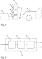
- a charging station 10 according to the invention is shown schematically.
- the charging station comprises a network connection unit 12, a transformer unit 14 and a charging unit 16.
- the charging station 10 Via the network connection unit 12, the charging station 10 is connected to a medium-voltage network section 18, i.e. to a medium-voltage network (shown in dashed lines because it does not belong to the charging station 10).
- An electric vehicle 20 can be connected via the charging unit 16 in order to charge the battery of the electric vehicle 20.
- the input voltage is transformed in the transformer unit 14, so that both a direct and an alternating current charging voltage can be provided.
- the charging station 10 is based on the fact that a connection is made directly to the medium-voltage network.
- the low-voltage network is therefore not used, but an alternating current input voltage with a voltage of, for example, 10, 20 or 30 kV is used directly.
- a transformation or transmission to a significantly lower charging voltage then takes place in the transformer unit 14.
- the direct connection to the medium-voltage network section 18 means that, despite a high electrical charging power, only a comparatively low charging current has to be drawn. Comparatively thin cable cross-sections can therefore be used.
- the low-voltage network which due to its architecture is often not designed to allow a higher number of electric vehicles to be charged at the same time, is spared. It is not necessary that sufficient capacity is available in the transformer stations between the medium-voltage and low-voltage network in order to charge a large number of electric vehicles if necessary.
- the charging station 10 shown is designed as a free-standing charging column.
- the charging station can be attached in particular in the public traffic area, at a parking lot or in a parking garage. In particular, rapid charging can be made possible.
- the design is small enough to allow efficient and flexible installation.
- the transformer unit 14 is designed as a solid state transformer (SST). Such an SST allows a direct voltage and an alternating voltage to be provided at the same time. In contrast to a conventional winding transformer, a medium-frequency transmission is carried out for this purpose.
- SST solid state transformer
- the incoming AC input voltage is rectified by means of an input-side (primary-side) power electronics unit 22 and its frequency is adjusted. In particular, the frequency is increased.
- a pulsating DC voltage is generated, so to speak, by chopping the input voltage.
- the pulse frequency is significantly increased compared to the input voltage.
- a frequency of several kHz, for example 5 kHz, is preferably generated.
- the transformer unit 14 comprises a transmission unit 24, which is connected downstream of the primary-side power electronics unit 22.
- the output of the primary-side Power electronics unit 22 is connected to transmission unit 24.
- the actual galvanic decoupling between the primary and secondary side takes place in the transmission unit 24.
- a high frequency transformation or transmission is carried out.
- the frequency can for example be between 100 Hz and 50 kHz, a transmission in the kHz range preferably being used.
- Such a high-frequency transmission requires that the overall size of the transformer unit 14 is significantly reduced compared to a conventional transformer structure.
- a secondary-side power electronics unit 26 Downstream of the transmission unit 24 there is a secondary-side power electronics unit 26 on the output side.
- This secondary-side power electronics unit 26 is coupled to the output of the transmission unit 24 and is supplied with the transformed voltage.
- the transmission unit 24 supplies a voltage of 400 or 800 V.
- a direct voltage (pulsating direct voltage) is provided. The frequency of this direct voltage is first adjusted in the secondary-side power electronics 26 in order to be made available as a direct current charging voltage.
- the secondary-side power electronics 26 are designed to also provide an alternating current charging voltage by means of an alternating direction. Both the DC charging voltage and the AC charging voltage can be used to charge the scooter.
- the network connection unit 12 is designed to be inserted into a ring network. To this extent there is a voltage input 28 and a voltage output 30.
- a branch for example a T-joint, would also be possible, which, however, would make a more complex implementation necessary due to the comparatively high voltage.
- a fuse unit 32 is located within the network connection unit, which prevents an arcing fault and / or its effects is limited.
- the fuse unit 32 includes appropriate insulation for this purpose.
- an insulating medium 34 is provided, by means of which the connection point and all parts carrying medium voltage, that is to say in particular the connection plug at the voltage input 28 and at the voltage output 30, are isolated.
- the network connection unit 12 comprises a disconnection unit 36.
- This disconnection unit is designed, for example, as a detachable switch. A connection between the medium-voltage network and the network connection or transformer unit can be released. The higher medium voltage makes a more complex construction of the network connection necessary compared to conventional charging stations or charging stations.
- a further embodiment of a charging station 10 'according to the invention embodied as a charging column is shown.
- the charging station 10 ' comprises a measuring unit 38, a control unit 40, a load control unit 42 and a communication unit 44.
- the above-mentioned units are optional and that in other embodiments of the charging station 10' it is also possible that only one selection of the units is included.
- the functions of the units mentioned below can be fulfilled by combined units, in so far as a single unit provides the function of several units.
- the functions of the units mentioned can be implemented partially or completely in hardware and / or in software.
- a microcontroller can be provided which partially or completely implements various functions of the aforementioned units.
- the measuring unit 38 can in particular comprise an ammeter with which the current flow transmitted to the electric vehicle can be measured.
- the transferred charging power is measured.
- billing i.e. payment of the related Charging by the owner of the electric vehicle.
- Both the power provided via the AC charging voltage and the power provided via the DC charging voltage can be measured and monitored in the measuring unit 38.
- the various parameters of the units of the charging station 10 ' can be controlled via the control unit. For example, it can be specified that the connection to the medium-voltage network is disconnected in the network connection unit.
- parameters of the measurement can be defined in the measuring unit 38 (for example measuring frequency, resolution, duration, etc.). It is also possible to switch individual outputs on and off. In particular, it can be determined via the control unit 40 whether a direct voltage or an alternating voltage is made available. It goes without saying that further control functions can also be made possible.
- the load control unit 42 is designed to determine the charging power provided. For example, it may be necessary to temporarily limit a maximum charging power. For this purpose, the load control unit 42 functions as a throttle.
- the load control unit 42 can also be integrated into the primary or secondary power electronics.
- a communication connection (wired or wireless) with a remote communication partner can be established via the communication unit 44.
- a communication link can be established with a central unit.
- communication it is also possible for communication to be established with a corresponding communication system integrated into the electric vehicle.
- the communication unit 44 can be implemented, for example, as a mobile communication unit, that is to say as a GSM module or the like. It is also possible for the communication unit 44 to be designed as a low-energy short-range communication unit, for example as a Zigbee or Bluetooth module.
- a system 46 according to the invention for charging an electric vehicle is shown.
- the system 46 includes a medium-voltage network section 18.
- the medium-voltage network section 18 is understood to be part of a medium-voltage network, in particular as the corresponding cabling in the area of the charging station.
- a number of charging stations 10 are preferably connected in series (ring circuit). Each charging station has a corresponding voltage input and a voltage output. Such a configuration can be advantageous, for example, in a parking lot or rest area or in a similar environment if several charging stations are necessary.
- the number of charging stations used is only limited by a maximum current flow in the medium-voltage network section 18. For example, such a maximum current flow can be in the range of 300 A, which at a voltage of 20 kV results in a very high overall potentially available charging power.
- system 46 in addition to the charging station 10 and the medium-voltage network section 18, the system 46 can also include a billing system 48, a load control system 50 and a control system 52, which in turn can also be connected to the medium-voltage network section 18.
- the billing system 48 is used to carry out billing.
- the charging services used, which were measured within the charging station 10, are therefore billed. For example, it communicates with a bank or a credit card provider in order to make a corresponding rebooking.
- the load control system 50 is preferably also connected to the medium-voltage network section 18 and monitors a voltage of the medium-voltage network section 18. As soon as the monitored voltage drops by a predetermined threshold value, individual charging stations in their Power down. This ensures that there is no failure and that the security of supply is guaranteed.
- the control system 52 serves to communicate with the control unit in the charging station 10 in order to carry out the control parameters required accordingly.
- control can take place on the basis of the control system 52.
- the optimal operating parameters can be specified and updated.
- the aforementioned systems 48, 50 and 52 can also be designed individually or in combination.
- a central system that is operated, for example, by a network operator, can provide the functions of the aforementioned systems. Communication can take place via the Internet.
Landscapes
- Engineering & Computer Science (AREA)
- Power Engineering (AREA)
- Transportation (AREA)
- Mechanical Engineering (AREA)
- Charge And Discharge Circuits For Batteries Or The Like (AREA)
- Electric Propulsion And Braking For Vehicles (AREA)
Description
- Die vorliegende Erfindung betrifft eine Ladestation sowie ein System und ein Verfahren zum Laden einer Batterie eines Elektromobils.
- Die fortschreitende Entwicklung hin zur Elektromobilität erfordert das Bereitstellen einer entsprechenden Ladeinfrastruktur zum Laden von Elektromobilen wie Elektroautos, Elektro-Lastkraftwagen oder auch Elektrozweiräder. Entsprechende Ladestationen sind dabei beispielsweise als Ladesäulen oder auch als Wandladestationen (Wallbox) ausgebildet. Die Ladestationen stellen die für das Laden der Batterien notwendige elektrische Leistung bereit. Elektromobile können zumeist im Umfeld der Ladestation abgestellt werden und für die Dauer des Ladevorgangs angekoppelt werden.
- Die Ladestationen können dabei Wechselstrom (AC) oder auch Gleichstrom (DC) bereitstellen. Für den eigentlichen Batterieladevorgang ist normalerweise das Anlegen einer Gleichspannung an die Batterie erforderlich. Wenn die Ladestation als Gleichstrom-Ladestation ausgebildet ist, kann gegebenenfalls auf eine weitere Umwandlung verzichtet werden und die bereitgestellte Spannung direkt an die Batterie angelegt werden. Das Ladegerät ist sozusagen in der Ladestation integriert. Fahrzeuge, die mit Wechselstrom geladen werden, verfügen über ein im Fahrzeug verbautes Ladegerät, das den Wechselstrom in Gleichstrom umwandelt. Vorteil eines Wechselstrom-Ladevorgangs ist, dass Wechselstrom in den meisten Haushalten sowie an anderen Stellen verfügbar ist. Daher ist keine weitere Umwandlung notwendig. Nachteilig ist die oftmals geringere erzielbare Ladeleistung. Moderne Schnellladesysteme basieren zumeist auf einer Gleichstromladung bei hoher Spannung, beispielsweise 400 oder 800 V. Bei derartigen Spannungen können Ladeleistungen im Bereich von 50 kW erreicht werden, sodass ein Ladevorgang eines Elektrofahrzeugs in einer Zeitspanne von ungefähr einer Stunde realisiert werden kann. Die erzielbaren Leistungen bei Wechselstrom-Ladestationen sind oft wesentlich geringer.
- Aus Netzsicht sind Ladestationen heutzutage oft basierend auf den bekannten Betriebsmitteln aufgebaut. In einer Verteilstation wird eine Mittelspannung (beispielsweise 10, 20 oder 30 kV) in eine Niederspannung (beispielsweise 230, 400 oder 1.000 V) transformiert. Die Niederspannung wird dann über ein entsprechendes Verteilnetz verteilt. Durch das Niederspannungs-Verteilnetz werden sowohl angeschlossene Endverbraucher als auch angeschlossene Ladestationen versorgt.
- Für die Netzbetreiber besteht in diesem Zusammenhang eine Herausforderung darin, dass mit zunehmender Anzahl von Ladestationen, die an einem einzelnen Niederspannungs-Kabelstrang angeschlossen sind, die Auslastung dieses Kabelstrangs stark ansteigen kann. Zudem erhöht sich auch der Spannungsabfall auf dem Kabelstrang. Oft sind zum gleichen Zeitpunkt, beispielsweise nach Feierabend, hohe Leistungen zum Laden angeschlossener Elektromobile notwendig. Pro Kabelstrang kann daher nur eine bestimmte Anzahl an Ladestationen vorgesehen werden. Sofern dann weitere Ladestationen erforderlich sind, muss ein weiterer Kabelstrang verlegt werden. Üblicherweise ist der Stromfluss im Niederspannungsnetz auf 250 A oder 315 A pro Kabelstrang begrenzt.
- In heutigen Niederspannungsnetzen werden in Verteilerstationen oft 630 kVA-Transformatoren verwendet. In typischen Planungsansätzen wäre ein derartiger Transformator überlastet, wenn 300 Wohneinheiten, von denen 80 Prozent über ein Elektroauto verfügen, angeschlossen werden. Problematisch an der Verwendung größerer Transformatoren ist der mit steigender Leistung wachsende Raum- und Platzbedarf, der in der vorhandenen Infrastruktur und zulässigen Bebauung oft nicht erfüllt werden kann.
- In diesem Zusammenhang werden in
DE 10 2016 102 053 A1 ein Schaltungssystem für eine Ladestation, eine Ladestation und eine Verwendung einer Ladestation offenbart. Das Schaltungssystem ist zum Aufladen eines Energiespeichers in einem Fahrzeug vorgesehen. Das Schaltungssystem umfasst einen Transformator mit voneinander galvanisch getrennten Transformatorausgängen. Ein erstes Subsystem und ein zweites Subsystem sind jeweils mit einem der Transformatorausgänge verbunden. Das erste Subsystem und das zweite Subsystem umfassen jeweils einen Gleichrichter, der einem Gleichspannungswandler vorgeschaltet ist. Der Gleichspannungswandler ist an seiner Eingangsseite oder an seiner Ausgangsseite an eine Umschaltlogik gekoppelt. Insbesondere ist es vorgesehen, dass das erste Subsystem an eine Dreiecksschaltung im Transformatorausgang und das zweite Subsystem an eine Sternschaltung im Transformatorausgang angeschlossen sind. - Die
US 2013/0020993 A1 betrifft eine Multimodus-Ladestation für Elektrofahrzeuge. Eine verkleinerte und vereinfachte Multimodus-Ladestation für elektrische Fahrzeuge wird bereitgestellt, die es einem Benutzer ermöglicht, zwischen einer AC- und DC-Ausgabe zu wählen. An eine Spannungsquelle ist ein DC-Konverter angeschlossen, der dann an einen DC-Bus oder an eine elektrische Verbindung ausgibt. Der DC-Bus kann von einer DC-Ladeausrüstung oder einem DC-AC-Inverter, der an eine AC-Ladeausrüstung angeschlossen ist, verwendet werden, wodurch eine DC- und AC-Lademöglichkeit bereitgestellt wird. - Die
US 2011/0055037 A1 betrifft ein Ladesystem, das an eine Energiequelle anschließbar ist. - Die
DE 10 2015 110 023 A1 betrifft eine Ladestation sowie ein Verfahren zum Laden eines Plug-in-Kraftfahrzeugs an einer Ladesäule. Die Ladestation umfasst einen Leistungstransformator und Gleichrichtermodule. Der Leistungs transformator weist sekundärseitig galvanisch getrennte Ableitungen auf. Die Ableitungen sind zumindest teilweise mit den Gleichrichtermodulen verbunden. Der Leistungstransformator sowie die Gleichrichtermodule sind derart konfiguriert, dass die Gleichrichtermodule eine Niedergleichspannung abgeben, wenn der Leistungstransformator mit einer Mittelspannung gespeist wird. - Die
EP 2 185 913 A1 betrifft ein Ladesystem für elektrische Fahrzeuge. Das Ladesystem umfasst einen Eingangsabschnitt zum Anbinden an ein Wechselspannungsnetz und einen Ausgangsabschnitt zum Anbinden an ein Elektrofahrzeug. Weiterhin umfasst das Ladesystem einen Umwandlungsabschnitt zum Umwandeln einer Wechselspannung in eine Gleichspannung sowie eine Steuereinheit, die zum Steuern des Umwandlungsabschnitts ausgebildet ist. - Ausgehend hiervon stellt sich der vorliegenden Erfindung die Aufgabe, unter Berücksichtigung der aktuellen Stromnetz-Infrastruktur ein effizientes Aufladen von Batterien von Elektromobilen zu ermöglichen. Einerseits soll auch bei der absehbaren weiteren Verbreitung der Elektromobilität die Versorgungssicherheit gewährleistet werden, andererseits sollen die notwendigen Anpassungen der Netzinfrastruktur bzw. die Kosten minimal gehalten werden.
- Diese Aufgabe wird erfindungsgemäß von einer Ladestation zum Laden einer Batterie eines Elektromobils gelöst. Die Ladestation umfasst:
- eine Netzanschlusseinheit zum Anbinden der Ladestation an einen Mittelspannungsnetzabschnitt und zum Beziehen einer Wechselstrom-Eingangsspannung, wobei die Wechselstrom-Eingangsspannung eine Mittelspannung ist;
- eine Transformatoreinheit zum Umwandeln der Wechselstrom-Eingangsspannung und zum Bereitstellen einer Wechselstrom-Ladespannung und einer Gleichstrom-Ladespannung; und
- eine Ladeeinheit zum Ankoppeln des Elektromobils, um die Batterie des Elektromobils mit der bereitgestellten Wechselstrom-Ladespannung und/oder der bereitgestellten Gleichstrom-Ladespannung zu laden,
- wobei die Ladestation als Ladesäule oder als Wandladestation ausgebildet ist.
- Ein weiterer Aspekt der Erfindung betrifft ein Verfahren zum Laden einer Batterie eines Elektromobils, mit den Schritten:
- Anbinden einer Ladestation an einen Mittelspannungsnetzabschnitt und Beziehen einer Wechselstrom-Eingangsspannung, wobei die Wechselstrom-Eingangsspannung eine Mittelspannung ist;
- Umwandeln der Wechselstrom-Eingangsspannung und Bereitstellen einer Wechselstrom-Ladespannung und einer Gleichstrom-Ladespannung; und
- Ankoppeln des Elektromobils, um die Batterie des Elektromobils mit der bereitgestellten Wechselstrom-Ladespannung und/oder der bereitgestellten Gleichstrom-Ladespannung zu laden,
- wobei die Ladestation als Ladesäule oder als Wandladestation ausgebildet ist.
- Zudem betrifft ein Aspekt der Erfindung ein System zum Laden einer Batterie eines Elektromobils, mit:
- einer Ladestation wie oben beschrieben; und
- einem Mittelspannungsnetzabschnitt, an den die Ladestation angebunden ist, um die Wechselstrom-Eingangsspannung zu beziehen.
- Bevorzugte Ausgestaltungen der Erfindung werden in den abhängigen Ansprüchen beschrieben. Es versteht sich, dass die Ladestation sowie das System und das Verfahren entsprechend der für die Ladestation und das System in den abhängigen Ansprüchen beschriebenen Ausgestaltungen ausgeführt sein können.
- Erfindungsgemäß ist es vorgesehen, dass die Ladestation direkt an einen Abschnitt (bzw. Teil) des Mittelspannungsnetzes angebunden ist und eine Wechselstrom-Eingangsspannung von diesem Mittelspannungsnetz bezieht. Das Mittelspannungsnetz ist dabei vorzugsweise ein 6, 10, 20 oder 30 kV-Netz, an das ansonsten üblicherweise lediglich Umspannstationen angeschlossen sind, die die Mittelspannung in eine Niederspannung transformieren, um Endverbraucher zu versorgen. Demgegenüber ist die Netzanschlusseinheit der erfindungsgemäßen Ladestation zum direkten Anschluss an die höheren Spannungen ausgeführt. Insbesondere verfügt die Netzanschlusseinheit vorzugsweise über die erforderlichen Sicherheits- und Isolationseinrichtungen.
- Die Wechselstrom-Eingangsspannung wird in der Transformatoreinheit dann einerseits in eine Wechselstrom-Ladespannung und andererseits in eine Gleichstrom-Ladespannung umgewandelt. Hierbei wird die Spannung ausgehend von der eingehenden höheren Spannung des Mittelspannungsnetzes vorzugsweise verringert, beispielsweise auf 400 oder 800 V.
- Über die Ladeeinheit können die beiden erzeugten Ladespannungen dann bereitgestellt werden, um das Laden der Batterie des Elektromobils zu ermöglichen. Insbesondere ist unter dem Begriff Ankoppeln in diesem Zusammenhang ein lösbares Anschließen zu verstehen, wobei die Ladeeinheit vorzugsweise einen entsprechenden Stecker sowie ein Kabel, das an das Elektromobil (entspricht in diesem Fall einem sog. Plug-In Elektromobil) anschließbar ist, umfasst. Es versteht sich, dass die Ladeeinheit aber auch in anderer Weise ausgeführt sein kann, beispielsweise zum induktiven Laden oder zum Laden eines aus einem Elektromobil entnehmbaren Moduls (Wechsel-Akku).
- Unter dem Begriff Elektromobil werden hierin insbesondere alle Arten von voll-und teilelektrisch (hybridelektrisch) angetriebenen Fahrzeugen mit aufladbarem Energiespeicher (Akku) verstanden, beispielsweise Elektroautos, Elektro-Lastkraftwagen oder auch Elektrozweiräder. Das erfindungsgemäße System umfasst neben der Ladestation noch einen Abschnitt eines Mittelspannungsnetzes, an den die Ladestation angebunden ist.
- Im Vergleich zu bisherigen Ladestationen, bei denen ein Anschluss an das Niederspannungsnetz erfolgte, wird die erfindungsgemäße Ladestation direkt an das Mittelspannungsnetz angeschlossen. Eine Transformation der Mittelspannung in die benötigte Ladespannung findet innerhalb der Säule statt. Hierdurch wird erreicht, dass die für den Ladevorgang erforderlichen vergleichsweise hohen Leistungen bereitgestellt werden können, ohne dass es zu einer übermäßigen Netzbelastung durch große Ströme kommt. Es wird vermieden, dass bisherige Umspannstationen zur Transformation der Mittelspannung in die Niederspannung über Gebühr belastet werden. Es ist nicht mehr erforderlich, dass größere Transformatoren mit hohen Leistungsreserven bereitgestellt werden. Dadurch, dass ein Mittelspannungskabel aufgrund der höheren Spannung deutlich mehr Energie transportieren kann als ein Niederspannungskabel, wird die mögliche Anzahl anschließbarer Ladestationen pro Kabelstrang sehr groß.
- Insoweit stellt die Erfindung einen dezentralen Ansatz dar, bei dem es nicht notwendig ist, zunächst den Zwischenschritt über das Niederspannungsnetz zu gehen. Durch Auflösen der Notwendigkeit eines zentralen Transformators wird der Raumbedarf auf die Aufstellfläche verlagert bzw. reduziert sich. Eine Anpassung der bestehenden Infrastruktur wird weitgehend vermieden, sodass Kosten eingespart werden können.
- Zudem ermöglicht die erfindungsgemäße Ladestation durch das gleichzeitige Bereitstellen einer Wechselstrom-Ladespannung und einer Gleichstrom-Ladespannung eine flexible Anwendbarkeit. Ein Anschluss und ein Laden eines Elektromobils sind möglich, egal ob ein Elektromobil mit oder ohne integriertem Ladegerät versorgt werden soll.
- In einer bevorzugten Ausgestaltung ist die Transformatoreinheit als Solid State Transformator, SST, ausgebildet ist. Ein SST erlaubt die gleichzeitige Erzeugung einer Wechselspannung und einer Gleichspannung. Aufgrund seiner Funktionsweise benötigt ein Solid State Transformator im Vergleich zu einem herkömmlichen Zwei- oder Dreiwicklungstransformator weniger Stellfläche bei gleicher Übertragungsleistung. Zudem kann die Umsetzung wesentlich kostengünstiger erfolgen. Insbesondere ermöglicht ein SST, dass gleichzeitig eine Wechselstrom-Ladespannung und eine Gleichstrom-Ladespannung bereitgestellt werden. Ein Einspeisen des SST mit hoher Spannung (Mittelspannung) ist möglich. Eine skalierbare Integration von Ladestationen in bestehende Netze kann sichergestellt werden.
- Bevorzugt umfasst die Transformatoreinheit eine Übertragungseinheit zum Ausführen einer Mittelfrequenzübertragung zur Spannungstransformation, vorzugsweise mit einer Frequenz zwischen 100 Hz und 50 kHz. Zum Durchführen einer Übertragung (Transformation) kann die eingehende Wechselstrom-Eingangsspannung (Mittelspannung) in eine (vorzugsweise niedrigere) Ladespannung transformiert werden. Die Spannungstransformation erfolgt dabei vorzugsweise mit einer Frequenz zwischen 100 Hz und 50 kHz. Üblicherweise werden Frequenzen im Bereich von mehreren kHz verwendet. Bei derartig hohen Frequenzen können hohe Leistungen bei geringem Platzbedarf übertragen werden. Bei vergleichbarer Leistung ist derselbe Transformator bzw. Übertrager wesentlich kleiner. Hierdurch wird erreicht, dass die Transformatoreinheit in eine Ladesäule oder in eine Wandladestation integriert werden kann. Die Notwendigkeit eines externen Transformators zwischen der Spannung des Mittelspannungsnetzes und der Spannung des Niederspannungsnetzes entfällt.
- In einer weiteren bevorzugten Ausgestaltung umfasst die Transformatoreinheit eine primärseitige Leistungselektronikeinheit, die dazu ausgebildet ist, eine Gleichrichtung und eine Frequenzanpassung der Wechselstrom-Eingangsspannung durchzuführen. Um die Frequenz der eingehenden Wechselstrom-Eingangsspannung anzupassen, ist eine eingangsseitige (primärseitige) Leistungselektronik vorgesehen, die eine Anpassung der Frequenz und eine Gleichrichtung erlaubt. Die Frequenz wird erhöht. Üblicherweise hat die eingehende Wechselstrom-Eingangsspannung eine Frequenz von 50 Hz. Die von der Leistungselektronik auf der Eingangsseite erzeugte Spannung hat eine wesentlich höhere Frequenz von beispielsweise einigen kHz. Durch die Verwendung einer Leistungselektronik kann eine entsprechende Gleichrichtung und Frequenzanpassung vorgenommen werden.
- In einer vorteilhaften Ausgestaltung umfasst die Transformatoreinheit eine sekundärseitige Leistungselektronikeinheit, die dazu ausgebildet ist, eine Frequenzanpassung durchzuführen, um die Gleichstrom-Ladespannung zu erzeugen; und eine Frequenzanpassung und eine Wechselrichtung durchzuführen, um die Wechselstrom-Ladespannung zu erzeugen. Ausgangsseitig, also sekundärseitig, wird die Frequenz erneut angepasst, um eine Ladespannung zu erzeugen. Für die Gleichstrom-Ladespannung ist es erforderlich, dass eine Frequenz angepasst wird. Für die Wechselstrom-Ladespannung muss zusätzlich eine Wechselrichtung durchgeführt werden.
- Vorteilhafterweise ist die Wechselstrom-Eingangsspannung eine Spannung zwischen 1 kV und 52 kV, vorzugsweise zwischen 10 kV und 30 kV; und/oder ist die Wechselstrom-Ladespannung und/oder die Gleichstrom-Ladespannung eine Spannung zwischen 200 V und 1000 V, vorzugsweise zwischen 350 V und 450 V. Übliche Mittelspannungsnetze werden mit 10, 20 oder 30 kV betrieben. Ladevorgänge von modernen Elektroautos finden oft bei Spannungen von 400 oder 800 V statt. Durch die Verwendung höherer Spannungen können die Ströme auch bei größeren Leistungen begrenzt werden. Die Verwendung von dicken Kabeln ist nicht notwendig.
- In einer bevorzugten Ausgestaltung ist die Ladestation als freistehende Ladesäule ausgebildet. Derartige freistehende Ladesäulen können beispielsweise im öffentlichen Verkehrsraum oder auch an Parkplätzen oder in Tiefgaragen verwendet werden. Durch einen Mittelspannungs-Netzanschluss kann ein schnelles Laden erreicht werden.
- In einer bevorzugten Ausgestaltung umfasst die Ladestation eine Messeinheit zum Ermitteln eines Verbrauchswerts, der die von dem Elektromobil bezogene Ladeenergie beschreibt. Die Messeinheit erlaubt es, die an das Elektromobil transferierte Ladeenergie zu messen. Hierdurch wird eine Abrechnung der bezogenen Ladeleistung gegenüber dem Netzbetreiber bzw. gegenüber dem Bereitsteller der Ladestation ermöglicht. Vorzugsweise umfasst die Messeinheit ein Strommessgerät. Durch die Bereitstellung einer Messeinheit direkt innerhalb der Ladestation kann eine einfache und gesicherte Abrechnung erfolgen. Ein Betrug wird erschwert.
- In einer weiteren Ausgestaltung umfasst die Ladestation eine Laststeuerungseinheit zum Festlegen einer bereitgestellten Ladeleistung. Durch das zusätzliche Verwenden einer Laststeuerungseinheit kann die bereitgestellte Leistung insbesondere limitiert werden. Es wird ermöglicht, dass eine zentrale Instanz regelnd und/oder steuernd eingreift, um eine Überlastung der Netze zu verhindern. Wenn beispielsweise gleichzeitig eine Vielzahl an Elektromobilen geladen werden soll, kann es zu einer Überlastung kommen. Eine Laststeuerungseinheit erlaubt sozusagen eine Drosselung der an einer einzelnen Ladestation bereitgestellten Leistung. Eine Überlastung wird vermieden.
- In einer weiteren vorteilhaften Ausgestaltung umfasst die Ladestation eine Kontrolleinheit zum Steuern der Netzanschlusseinheit, um die Anbindung an den Mittelspannungsnetzabschnitt zu beeinflussen; der Ladeeinheit, um einen Ladevorgang des Elektromobils zu beeinflussen; und/oder der Transformatoreinheit, um die Umwandlung zu beeinflussen. Hierbei kann eine Beeinflussung insbesondere eine Steuerung und/oder eine Regelung umfassen. Sowohl die Netzanschlusseinheit als auch die Ladeeinheit und die Transformatoreinheit können separat beeinflusst werden. Unter einem Beeinflussen versteht sich dabei insbesondere eine Einstellung von Parametern, um die Funktionen der Einheiten anzupassen. Es werden die Eigenschaften der verschiedenen Einheiten im Betrieb modifiziert. Es wird erreicht, dass je nach Art des zu ladenden Elektromobils ein optimierter Ladevorgang durchgeführt werden kann. Die Kontrolleinheit kann dabei beispielsweise bei einer Laststeuerung mitwirken. Es ist auch möglich, dass die Kontrolleinheit sicherheitsrelevante Funktionen, wie zum Beispiel das Abtrennen vom Mittelspannungsnetz, umsetzt.
- In einer vorteilhaften Ausgestaltung umfasst die Ladestation eine Kommunikationseinheit die vorzugsweise als Mobilkommunikationseinheit ausgebildet ist, zum Kommunizieren mit einem Abrechnungssystem, um den Verbrauchswert zu übermitteln; einem Laststeuerungssystem, um Lastparameter der Laststeuerungseinheit zum Festlegen der Ladeleistung festzulegen; und/oder einem Kontrollsystem, um Kontrollparameter der Kontrolleinheit festzulegen. Die Kommunikationseinheit ermöglicht es, dass eine Kommunikationsverbindung mit einem anderen System hergestellt wird. Insbesondere kann mit einer zentralen Instanz (z.B. zentraler Server, Kontrollsystem etc.) kommuniziert werden. Beispielsweise kann durch eine Kommunikation mit einem Abrechnungssystem eine Abrechnung der vom Elektromobil aufgenommenen elektrischen Leistung erfolgen. Von einem zentralen Laststeuerungssystem kann eine Festlegung der bereitgestellten Leistung vorgenommen werden. Eine zentrale Steuerung kann über die Kontrolleinheit erfolgen. Durch die Kommunikationseinheit wird es damit ermöglicht, dass eine Vor-Ort-Wartung sowie ein Vor-Ort-Zugriff auf die Ladestation weitgehend vermieden werden können, sodass Kosten gespart werden.
- In einer weiteren vorteilhaften Ausgestaltung umfasst die Netzanschlusseinheit eine Sicherungseinheit zum Verhindern und/oder Begrenzen der Wirkung eines Störlichtbogens; ein Isoliermedium zum Isolieren der Wechselstrom-Eingangsspannung; und/oder eine Abtrenneinheit zum Abtrennen der Transformatoreinheit von der Wechselstrom-Eingangsspannung. Verschiedene Sicherheitsfunktionen können realisiert werden. Dies ist insbesondere erforderlich, da die Wechselstrom-Eingangsspannung eine andere Behandlung als die bisher übliche Niederspannung notwendig macht. So muss beispielsweise ein Störlichtbogen verhindert bzw. in seiner Wirkung begrenzt werden und ein geeignetes Isoliermedium verwendet werden. Durch die Abtrenneinheit kann ein Abtrennen vom Mittelspannungsnetz erfolgen, das beispielsweise dann erforderlich ist, wenn bei einem Defekt eine Reparatur vorgenommen oder die Transformatoreinheit ausgetauscht werden muss. Die Sicherheit wird erhöht. Eine möglichst hohe Verfügbarkeit wird sichergestellt.
- In einer vorteilhaften Ausgestaltung umfasst das erfindungsgemäße System ein Abrechnungssystem zum Empfangen eines Verbrauchswerts, um darauf basierend eine Abrechnung durchzuführen; ein Laststeuerungssystem zum Übermitteln von Lastparametern an eine Laststeuerungseinheit der Ladestation, um die von der Ladestation bereitgestellte Ladeleistung festzulegen; und/oder ein Kontrollsystem zum Festlegen von Kontrollparametern einer Kontrolleinheit einer Ladestation, um eine Netzanschlusseinheit, eine Ladeeinheit und/oder eine Transformatoreinheit einer Ladestation zu steuern.
- Es versteht sich, dass die vorstehend genannten und die nachstehend noch zu erläuternden Merkmale nicht nur in der jeweils angegebenen Kombination, sondern auch in anderen Kombinationen oder in Alleinstellung verwendet werden können, ohne den Rahmen der vorliegenden Erfindung zu verlassen. Die Erfindung wir nachfolgend anhand einiger ausgewählter Ausführungsbeispiele im Zusammenhang mit den beiliegenden Zeichnungen näher beschrieben und erläutert. Es zeigen:
- Figur 1
- eine schematische Darstellung einer erfindungsgemäßen Ladestation zum Laden einer Batterie eines Elektromobils;
- Figur 2
- eine schematische Darstellung einer Transformatoreinheit zur Verwendung in einer Ladestation;
- Figur 3
- eine schematische Darstellung einer Netzanschlusseinheit zur Verwendung in einer Ladestation;
- Figur 4
- eine schematische Darstellung einer weiteren Ausführungsform der Ladestation;
- Figur 5
- eine schematische Darstellung eines erfindungsgemäßen Systems zum Laden einer Batterie eines Elektromobils;
- Figur 6
- eine schematische Darstellung einer weiteren Ausführungsform des Systems; und
- Figur 7
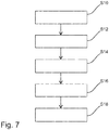
- eine schematische Darstellung eines erfindungsgemäßen Verfahrens.
- In der
Figur 1 ist eine erfindungsgemäße Ladestation 10 schematisch dargestellt. Die Ladestation umfasst eine Netzanschlusseinheit 12, eine Transformatoreinheit 14 sowie eine Ladeeinheit 16. Über die Netzanschlusseinheit 12 ist die Ladestation 10 an einen Mittelspannungsnetzabschnitt 18, also an ein Mittelspannungsnetz, angebunden (gestrichelt dargestellt, da nicht zur Ladestation 10 gehörend). Über die Ladeeinheit 16 kann ein Elektromobil 20 angeschlossen werden, um die Batterie des Elektromobils 20 zu laden. In der Transformatoreinheit 14 wird die Eingangsspannung transformiert, sodass sowohl eine Gleich- als auch eine Wechselstrom-Ladespannung bereitgestellt werden können. - Die erfindungsgemäße Ladestation 10 basiert darauf, dass ein Anschluss direkt an das Mittelspannungsnetz erfolgt. Es wird also nicht auf das Niederspannungsnetz zurückgegriffen, sondern direkt eine Wechselstrom-Eingangsspannung mit einer Spannung von beispielsweise 10, 20 oder 30 kV verwendet. In der Transformatoreinheit 14 findet dann eine Transformation bzw. eine Übertragung auf eine wesentlich geringere Ladespannung statt.
- Durch den direkten Anschluss an den Mittelspannungsnetzabschnitt 18 wird erreicht, dass trotz einer hohen elektrischen Ladeleistung nur ein vergleichsweise geringer Ladestrom bezogen werden muss. Es kann also auf vergleichsweise dünne Kabelquerschnitte zurückgegriffen werden. Das Niederspannungsnetz, das aufgrund seiner Architektur oft nicht dazu ausgelegt ist, das gleichzeitige Laden einer höheren Anzahl von Elektromobilen zur erlauben, wird geschont. Es ist nicht notwendig, dass in den Umspannstationen zwischen Mittelspannungs- und Niedrigspannungsnetz eine ausreichende Kapazität vorgehalten wird, um gegebenenfalls eine hohe Anzahl an Elektromobilen zu laden.
- Die dargestellte Ladestation 10 ist als freistehende Ladesäule ausgebildet. Die Ladesäule kann dabei insbesondere im öffentlichen Verkehrsraum, an einem Parkplatz oder in einem Parkhaus angebracht sein. Insbesondere kann ein Schnellladen ermöglicht werden. Die Bauform ist klein genug, um ein effizientes und flexibles Aufstellen zu erlauben.
- Das gleichzeitige Bereitstellen einer Wechsel- und einer Gleichstrom-Ladespannung erlaubt eine flexible Verwendung der Ladestation. Es können Elektromobile mit oder ohne eigenem Ladegerät geladen werden. Üblicherweise ist ein Schalter oder eine andere Einstellmöglichkeit zur Auswahl der Spannungsform für das gerade angeschlossene Elektromobil vorgesehen. Vorteilhafterweise ist eine Einrichtung vorgesehen, durch die sichergestellt wird, dass nur die jeweils korrekte Spannungsform an ein Elektromobil weitergeleitet wird. Zum Beispiel können verschiedene Stecker verwendet werden.
- In der
Figur 2 ist eine Ausführungsform der Transformatoreinheit 14 in einer schematischen Detailansicht dargestellt. Die Transformatoreinheit 14 ist als Solid State Transformator (SST) ausgebildet. Ein derartiger SST erlaubt das gleichzeitige Bereitstellen einer Gleichspannung und einer Wechselspannung. Im Gegensatz zu einem konventionellen Wicklungstransformator wird hierzu eine Mittelfrequenzübertragung ausgeführt. - Zunächst wird die eingehende Wechselstrom-Eingangsspannung mittels einer eingangsseitigen (primärseitigen) Leistungselektronikeinheit 22 gleichgerichtet und in ihrer Frequenz angepasst. Insbesondere wird eine Erhöhung der Frequenz durchgeführt. Zudem wird sozusagen durch eine Zerhackung der Eingangsspannung eine pulsierende Gleichspannung erzeugt. Die Pulsfrequenz wird dabei gegenüber der Eingangsspannung deutlich erhöht. Vorzugsweise wird eine Frequenz von mehreren kHz, beispielsweise 5 kHz erzeugt.
- Weiterhin umfasst die Transformatoreinheit 14 in der dargestellten Ausführungsform eine Übertragungseinheit 24, die der primärseitigen Leistungselektronikeinheit 22 nachgeschaltet ist. Der Ausgang der primärseitigen Leistungselektronikeinheit 22 ist mit der Übertragungseinheit 24 verbunden. In der Übertragungseinheit 24 findet die eigentliche galvanische Entkopplung zwischen Primär- und Sekundärseite statt. Es wird eine Hochfrequenztransformation bzw. -übertragung durchgeführt. Die Frequenz kann dabei beispielsweise zwischen 100 Hz und 50 kHz liegen, wobei bevorzugt eine Übertragung im kHz-Bereich verwendet wird. Eine derartige Hochfrequenzübertragung bedingt, dass die gesamte Baugröße der Transformatoreinheit 14 gegenüber einem herkömmlichen Transformatoraufbau deutlich verringert wird.
- Der Übertragungseinheit 24 nachgeschaltet befindet sich ausgangsseitig eine sekundärseitige Leistungselektronikeinheit 26. Diese sekundärseitige Leistungselektronikeinheit 26 ist an den Ausgang der Übertragungseinheit 24 angekoppelt und wird mit der transformierten Spannung versorgt. Beispielsweise liefert die Übertragungseinheit 24 eine Spannung von 400 oder 800 V. Es wird eine Gleichspannung (pulsierende Gleichspannung) bereitgestellt. Diese Gleichspannung wird in der sekundärseitigen Leistungselektronik 26 zunächst in ihrer Frequenz angepasst, um als Gleichstrom-Ladespannung zur Verfügung gestellt zu werden. Zudem ist die sekundärseitige Leistungselektronik 26 dazu ausgebildet, durch eine Wechselrichtung ebenfalls eine Wechselstrom-Ladespannung bereitzustellen. Sowohl die Gleichstrom-Ladespannung als auch die Wechselstrom-Ladespannung können zum Laden des Elektromobils verwendet werden.
- In der
Figur 3 findet sich eine detailliertere schematische Darstellung der Netzanschlusseinheit 12. In der dargestellten Ausführungsform ist die Netzanschlusseinheit zum Einfügen in ein Ringnetz ausgebildet. Es gibt insoweit einen Spannungseingang 28 und einen Spannungsausgang 30. Alternativ wäre auch die Verwendung eines Abzweigs, beispielsweise einer T-Muffe, möglich, die aufgrund der vergleichsweise hohen Spannung jedoch eine komplexere Implementierung notwendig machen würde. - Innerhalb der Netzanschlusseinheit befindet sich eine Sicherungseinheit 32, durch die ein Störlichtbogen verhindert und/oder dessen Auswirkungen begrenzt wird. Insbesondere umfasst die Sicherungseinheit 32 dazu eine entsprechende Isolation. Zusätzlich ist ein Isoliermedium 34 vorgesehen, durch das die Anschlussstelle und alle mittelspannungsführenden Teile, also insbesondere der Anschlussstecker am Spannungseingang 28 sowie am Spannungsausgang 30 isoliert werden.
- Um ein Abtrennen der Transformatoreinheit zu ermöglichen, sodass beispielsweise eine Wartung durchgeführt oder ein Austausch vorgenommen werden kann, umfasst die Netzanschlusseinheit 12 eine Abtrenneinheit 36. Diese Abtrenneinheit ist beispielsweise als lösbarer Schalter ausgebildet. Eine Verbindung zwischen Mittelspannungsnetz und Netzanschluss- bzw. Transformatoreinheit kann gelöst werden. Die höhere Mittelspannung macht dabei einen aufwändigeren Aufbau des Netzanschlusses im Vergleich zu herkömmlichen Ladestationen bzw. Ladesäulen erforderlich.
- In der
Figur 4 ist eine weitere Ausführungsform einer als Ladesäule ausgebildeten erfindungsgemäßen Ladestation 10' dargestellt. Die Ladestation 10' umfasst eine Messeinheit 38, eine Kontrolleinheit 40, eine Laststeuerungseinheit 42 sowie eine Kommunikationseinheit 44. Es versteht sich, dass die vorstehend genannten Einheiten optional sind und dass es in anderen Ausführungsformen der Ladestation 10' auch möglich ist, dass nur eine Auswahl der Einheiten umfasst ist. Ebenfalls ist es möglich, dass die im Folgenden erwähnten Funktionen der Einheiten von kombinierten Einheiten erfüllt werden, insoweit also eine einzelne Einheit die Funktion mehrerer Einheiten bereitstellt. Es versteht sich zudem, dass die Funktionen der genannten Einheiten teilweise oder vollständig in Hard- und/oder in Software implementiert sein können. Insbesondere kann ein Mikrocontroller vorgesehen sein, der verschiedene Funktionen der zuvor genannten Einheiten teilweise oder vollständig umsetzt. - Die Messeinheit 38 kann insbesondere einen Strommesser umfassen, mit dem der an das Elektromobil übertragene Stromfluss gemessen werden kann. Es wird die übertragene Ladeleistung gemessen. Basierend auf einer derartigen Messung kann eine Abrechnung, also ein Bezahlen der bezogenen Ladeleistung durch den Eigentümer des Elektromobils, erfolgen. Sowohl die über die Wechselstrom-Ladespannung bereitgestellte Leistung als auch die über die Gleichstrom-Ladespannung bereitgestellte Leistung können dabei in der Messeinheit 38 gemessen und überwacht werden.
- Über die Kontrolleinheit können die verschiedenen Parameter der Einheiten der Ladestation 10' gesteuert werden. Beispielsweise kann festgelegt werden, dass in der Netzanschlusseinheit die Anbindung an das Mittelspannungsnetz getrennt wird. Zudem können Parameter der Messung in der Messeinheit 38 festgelegt werden (beispielsweise Messfrequenz, Auflösung, Dauer etc.). Ebenfalls ist es möglich, dass einzelne Ausgänge an- und ausgeschaltet werden. Insbesondere kann über die Kontrolleinheit 40 festgelegt werden, ob eine Gleich- oder eine Wechselspannung zur Verfügung gestellt wird. Es versteht sich, dass auch weitere Steuerungsfunktionen ermöglicht werden können.
- Die Laststeuerungseinheit 42 ist dazu ausgebildet, die bereitgestellte Ladeleistung festzulegen. Beispielsweise kann es erforderlich sein, dass eine maximale Ladeleistung vorübergehend begrenzt wird. Hierzu funktioniert die Laststeuerungseinheit 42 als Drosselung. Die Laststeuerungseinheit 42 kann dabei auch in die primär- oder sekundärseitige Leistungselektronik integriert sein.
- Über die Kommunikationseinheit 44 kann eine Kommunikationsverbindung (drahtgebunden oder auch drahtlos) mit einem entfernten Kommunikationspartner hergestellt werden. Insbesondere ist es möglich, dass eine Kommunikationsverbindung mit einer zentralen Einheit hergestellt wird. Es ist aber auch möglich, dass eine Kommunikation mit einem in das Elektromobil integrierten korrespondierenden Kommunikationssystem hergestellt wird. Die Kommunikationseinheit 44 kann dabei beispielsweise als Mobilkommunikationseinheit, also als GSM-Modul oder ähnliches implementiert sein. Es ist auch möglich, dass die Kommunikationseinheit 44 als Niedrigenergie-Kurzstreckenkommunikationseinheit ausgebildet ist, beispielsweise als Zigbee- oder Bluetoothmodul.
- In der
Figur 5 ist ein erfindungsgemäßes System 46 zum Laden eines Elektromobils dargestellt. Neben zumindest einer Ladestation 10 umfasst das System 46 einen Mittelspannungsnetzabschnitt 18. Der Mittelspannungsnetzabschnitt 18 versteht sich dabei als Teil eines Mittelspannungsnetzes, insbesondere als die entsprechende Verkabelung im Bereich der Ladestation. - Wie dargestellt sind vorzugsweise eine Anzahl an Ladestationen 10 in Reihe geschaltet (Ringschaltung). Jede Ladestation verfügt dabei über einen entsprechenden Spannungseingang und einen Spannungsausgang. Eine derartige Konfiguration kann beispielsweise auf einem Park- oder Rastplatz oder in einem ähnlichen Umfeld vorteilhaft sein, wenn mehrere Ladestationen notwendig sind. Die Anzahl der verwendeten Ladestationen ist dabei nur durch einen maximalen Stromfluss im Mittelspannungsnetzabschnitt 18 begrenzt. Beispielsweise kann ein derartiger maximaler Stromfluss im Bereich von 300 A liegen, was bei einer Spannung von 20 kV in einer sehr hohen insgesamt potentiell verfügbaren Ladeleistung resultiert.
- In der
Figur 6 ist das erfindungsgemäße System 46 in anderer Weise dargestellt. Neben der Ladestation 10 und dem Mittelspannungsnetzabschnitt 18 kann das System 46 zudem ein Abrechnungssystem 48, ein Laststeuerungssystem 50 sowie ein Kontrollsystem 52 umfassen, die ihrerseits ebenfalls an den Mittelspannungsnetzabschnitt 18 angebunden sein können. - Das Abrechnungssystem 48 dient dabei zur Durchführung einer Abrechnung. Es werden also die bezogenen Ladeleistungen, die innerhalb der Ladestation 10 gemessen wurden, abgerechnet. Beispielsweise wird mit einer Bank oder einem Kreditkartenanbieter kommuniziert, um eine entsprechende Umbuchung vorzunehmen.
- Das Laststeuerungssystem 50 ist vorzugsweise ebenfalls an dem Mittelspannungsnetzabschnitt 18 angeschlossen und überwacht eine Spannung des Mittelspannungsnetzabschnitts 18. Sobald die überwachte Spannung um einen vorgegebenen Schwellwert abfällt, werden einzelne Ladestationen in ihrer Leistung heruntergeregelt. Hierdurch wird erreicht, dass es nicht zu einem Ausfall kommt und die Versorgungssicherheit gewährleistet bleibt.
- Das Kontrollsystem 52 dient dazu, mit der Kontrolleinheit in der Ladestation 10 zu kommunizieren, um die entsprechend erforderlichen Kontrollparameter vorzunehmen. Insbesondere kann eine Steuerung ausgehend vom Kontrollsystem 52 erfolgen. Es können die optimalen Betriebsparameter vorgegeben werden und aktualisiert werden.
- Auch die vorstehend genannten Systeme 48, 50 und 52 können einzeln oder in Kombination ausgeführt sein können. Insbesondere kann ein Zentralsystem, das beispielsweise von einem Netzbetreiber betrieben wird, die Funktionen der zuvor genannten Systeme erbringen. Die Kommunikation kann dabei über das Internet erfolgen.
- In der
Figur 7 ist das erfindungsgemäße Verfahren schematisch illustriert. Die Schritte des Anbindens S10 der Ladestation an den Mittelspannungsnetzabschnitt, des Beziehens S12 der Eingangsspannung, des Umwandelns S14 der Spannung, des Bereitstellens S16 der Ladespannungen und des Ankoppelns S18 des Elektromobils können vollständig oder teilweise automatisiert ausgeführt werden. - Die Erfindung wurde anhand der Zeichnungen und der Beschreibung umfassend beschrieben und erklärt. Die Beschreibung und Erklärung sind als Beispiel und nicht einschränkend zu verstehen. Die Erfindung ist nicht auf die offenbarten Ausführungsformen beschränkt. Andere Ausführungsformen oder Variationen ergeben sich für den Fachmann bei der Verwendung der vorliegenden Erfindung sowie bei einer genauen Analyse der Zeichnungen, der Offenbarung und der nachfolgenden Patentansprüche.
- In den Patentansprüchen schließen die Wörter "umfassen" und "mit" nicht das Vorhandensein weiterer Elemente oder Schritte aus. Der undefinierte Artikel "ein" oder "eine" schließt nicht das Vorhandensein einer Mehrzahl aus. Ein einzelnes Element oder eine einzelne Einheit kann die Funktionen mehrerer der in den Patentansprüchen genannten Einheiten ausführen. Die verschiedenen Einheiten können teilweise oder vollständig in Hard- oder auch in Software ausgeführt sein. Die bloße Nennung einiger Maßnahmen in mehreren verschiedenen abhängigen Patentansprüchen ist nicht dahingehend zu verstehen, dass eine Kombination dieser Maßnahmen nicht ebenfalls vorteilhaft verwendet werden kann. Bezugszeichen in den Patentansprüchen sind nicht einschränkend zu verstehen.
Claims (15)
- Ladestation (10, 10') zum Laden einer Batterie eines Elektromobils (20), mit:einer Netzanschlusseinheit (12) zum Anbinden der Ladestation an einen Mittelspannungsnetzabschnitt (18) und zum Beziehen einer Wechselstrom-Eingangsspannung, wobei die Wechselstrom-Eingangsspannung eine Mittelspannung ist;einer Transformatoreinheit (14) zum Umwandeln der Wechselstrom-Eingangsspannung und zum Bereitstellen einer Wechselstrom-Ladespannung und einer Gleichstrom-Ladespannung; undeiner Ladeeinheit (16) zum Ankoppeln des Elektromobils, um die Batterie des Elektromobils mit der bereitgestellten Wechselstrom-Ladespannung und/oder der bereitgestellten Gleichstrom-Ladespannung zu laden,wobei die Ladestation als Ladesäule oder als Wandladestation ausgebildet ist.
- Ladestation (10, 10') nach Anspruch 1, wobei die Transformatoreinheit (14) als Solid State Transformator, SST, ausgebildet ist.
- Ladestation (10, 10') nach einem der vorstehenden Ansprüche, wobei die Transformatoreinheit (14) eine Übertragungseinheit (24) zum Ausführen einer Mittelfrequenzübertragung zur Spannungstransformation, vorzugsweise mit einer Frequenz zwischen 100 Hz und 50 kHz, umfasst.
- Ladestation (10, 10') nach einem der vorstehenden Ansprüche, wobei die Transformatoreinheit (14) eine primärseitige Leistungselektronikeinheit (22) umfasst, die dazu ausgebildet ist, eine Gleichrichtung und eine Frequenzanpassung der Wechselstrom-Eingangsspannung durchzuführen.
- Ladestation (10, 10') nach einem der vorstehenden Ansprüche, wobei die Transformatoreinheit (14) eine sekundärseitige Leistungselektronikeinheit (26) umfasst, die dazu ausgebildet ist,
eine Frequenzanpassung durchzuführen, um die Gleichstrom-Ladespannung zu erzeugen; und
eine Frequenzanpassung und eine Wechselrichtung durchzuführen, um die Wechselstrom-Ladespannung zu erzeugen. - Ladestation (10, 10') nach einem der vorstehenden Ansprüche, wobei
die Wechselstrom-Eingangsspannung eine Spannung zwischen 1 kV und 52 kV, vorzugsweise zwischen 10 kV und 30 kV, ist; und/oder
die Wechselstrom-Ladespannung und/oder die Gleichstrom-Ladespannung eine Spannung zwischen 200 V und 1000 V, vorzugsweise zwischen 350 V und 450 V, ist. - Ladestation (10, 10') nach einem der vorstehenden Ansprüche, wobei die Ladestation als freistehende Ladesäule ausgebildet ist.
- Ladestation (10, 10') nach einem der vorstehenden Ansprüche mit einer Messeinheit (38) zum Ermitteln eines Verbrauchswerts, der die von dem Elektromobil (20) bezogene Ladeenergie beschreibt.
- Ladestation (10, 10') nach einem der vorstehenden Ansprüche mit einer Laststeuerungseinheit (42) zum Festlegen einer bereitgestellten Ladeleistung.
- Ladestation (10, 10') nach einem der vorstehenden Ansprüche mit einer Kontrolleinheit (40) zum Steuern
der Netzanschlusseinheit (12), um die Anbindung an den Mittelspannungsnetzabschnitt (18) zu beeinflussen;
der Ladeeinheit (16), um einen Ladevorgang des Elektromobils (20) zu beeinflussen; und/oder
der Transformatoreinheit (14), um die Umwandlung zu beeinflussen. - Ladestation (10, 10') nach einem der Ansprüche 8 bis 10 mit einer Kommunikationseinheit (44), die vorzugsweise als Mobilkommunikationseinheit ausgebildet ist, zum Kommunizieren mit
einem Abrechnungssystem (48), um den Verbrauchswert zu übermitteln;
einem Laststeuerungssystem (50), um Lastparameter der Laststeuerungseinheit (42) zum Regeln der Ladeenergie festzulegen; und/oder
einem Kontrollsystem (52), um Kontrollparameter der Kontrolleinheit (40) festzulegen. - Ladestation (10, 10') nach einem der vorstehenden Ansprüche, wobei die Netzanschlusseinheit (12)
eine Sicherungseinheit (32) zum Verhindern und/oder Begrenzen der Wirkung eines Störlichtbogens;
ein Isoliermedium (34) zum Isolieren der Wechselstrom-Eingangsspannung; und/oder
eine Abtrenneinheit (36) zum Abtrennen der Transformatoreinheit (14) von der Wechselstrom-Eingangsspannung umfasst. - Verfahren zum Laden einer Batterie eines Elektromobils (20), mit den Schritten:Anbinden (S10) einer Ladestation (10, 10') nach Anspruch 1 an einen Mittelspannungsnetzabschnitt und Beziehen (S12) einer Wechselstrom-Eingangsspannung, wobei die Wechselstrom-Eingangsspannung eine Mittelspannung ist;Umwandeln (S14) der Wechselstrom-Eingangsspannung und Bereitstellen (S16) einer Wechselstrom-Ladespannung und einer Gleichstrom-Ladespannung; undAnkoppeln (S18) des Elektromobils, um die Batterie des Elektromobils mit der bereitgestellten Wechselstrom-Ladespannung und/oder der bereitgestellten Gleichstrom-Ladespannung zu laden,wobei die Ladestation als Ladesäule oder als Wandladestation ausgebildet ist.
- System (46) zum Laden einer Batterie eines Elektromobils (20), mit:einer Ladestation (10, 10') nach einem der Ansprüche 1 bis 12; undeinem Mittelspannungsnetzabschnitt (18), an den die Ladestation angebunden ist, um die Wechselstrom-Eingangsspannung zu beziehen.
- System (46) nach Anspruch 14, mit:einem Abrechnungssystem (48) zum Empfangen eines Verbrauchswerts, um darauf basierend eine Abrechnung durchzuführen;einem Laststeuerungssystem (50) zum Übermitteln von Lastparametern an eine Laststeuerungseinheit (42) der Ladestation, um die von der Ladestation (10, 10') bereitgestellte Ladeenergie zu regeln; und/odereinem Kontrollsystem (52) zum Festlegen von Kontrollparametern einer Kontrolleinheit (40) einer Ladestation, um eine Netzanschlusseinheit (12), eine Ladeeinheit (16) und/oder eine Transformatoreinheit (14) einer Ladestation zu steuern.
Priority Applications (2)
| Application Number | Priority Date | Filing Date | Title |
|---|---|---|---|
| ES18159787T ES2879843T3 (es) | 2018-03-02 | 2018-03-02 | Estación de carga y sistema de carga para vehículos eléctricos |
| EP18159787.3A EP3533658B1 (de) | 2018-03-02 | 2018-03-02 | Ladestation und ladesystem für elektromobile |
Applications Claiming Priority (1)
| Application Number | Priority Date | Filing Date | Title |
|---|---|---|---|
| EP18159787.3A EP3533658B1 (de) | 2018-03-02 | 2018-03-02 | Ladestation und ladesystem für elektromobile |
Publications (2)
| Publication Number | Publication Date |
|---|---|
| EP3533658A1 EP3533658A1 (de) | 2019-09-04 |
| EP3533658B1 true EP3533658B1 (de) | 2021-04-28 |
Family
ID=61563205
Family Applications (1)
| Application Number | Title | Priority Date | Filing Date |
|---|---|---|---|
| EP18159787.3A Active EP3533658B1 (de) | 2018-03-02 | 2018-03-02 | Ladestation und ladesystem für elektromobile |
Country Status (2)
| Country | Link |
|---|---|
| EP (1) | EP3533658B1 (de) |
| ES (1) | ES2879843T3 (de) |
Families Citing this family (3)
| Publication number | Priority date | Publication date | Assignee | Title |
|---|---|---|---|---|
| CN113452010B (zh) * | 2020-03-27 | 2023-06-13 | 比亚迪股份有限公司 | 轨道交通供电系统及轨道交通供电系统的控制方法 |
| CN113223385A (zh) * | 2021-04-25 | 2021-08-06 | 深圳职业技术学院 | 一种基于新能源汽车充电过程的充电原理演示系统 |
| CN113415203B (zh) * | 2021-06-29 | 2023-07-04 | 湖南昌茂电能发展有限公司 | 一种基于物联网的智能充电桩管理系统 |
Citations (1)
| Publication number | Priority date | Publication date | Assignee | Title |
|---|---|---|---|---|
| EP2815913A1 (de) * | 2013-06-18 | 2014-12-24 | Eutecne S.p.A. | Ladeanordnung für elektrische Fahrzeuge |
Family Cites Families (4)
| Publication number | Priority date | Publication date | Assignee | Title |
|---|---|---|---|---|
| WO2011019855A1 (en) * | 2009-08-11 | 2011-02-17 | Aerovironment, Inc. | Stored energy and charging appliance |
| US20130020993A1 (en) * | 2011-07-18 | 2013-01-24 | Green Charge Networks Llc | Multi-Mode Electric Vehicle Charging Station |
| DE102015110023A1 (de) * | 2015-06-23 | 2016-12-29 | Dr. Ing. H.C. F. Porsche Aktiengesellschaft | Ladestation und Verfahren zum Laden eines Plug-In-Kraftfahrzeuges an einer Ladesäule |
| DE102016102053A1 (de) | 2016-02-05 | 2017-08-10 | Dr. Ing. H.C. F. Porsche Aktiengesellschaft | Schaltungssystem für eine Ladestation, Ladestation und Verwenden einer Ladestation |
-
2018
- 2018-03-02 EP EP18159787.3A patent/EP3533658B1/de active Active
- 2018-03-02 ES ES18159787T patent/ES2879843T3/es active Active
Patent Citations (1)
| Publication number | Priority date | Publication date | Assignee | Title |
|---|---|---|---|---|
| EP2815913A1 (de) * | 2013-06-18 | 2014-12-24 | Eutecne S.p.A. | Ladeanordnung für elektrische Fahrzeuge |
Also Published As
| Publication number | Publication date |
|---|---|
| EP3533658A1 (de) | 2019-09-04 |
| ES2879843T3 (es) | 2021-11-23 |
Similar Documents
| Publication | Publication Date | Title |
|---|---|---|
| DE102019211553B4 (de) | Bidirektionale DC-Wallbox für Elektrofahrzeuge | |
| EP2670624B1 (de) | Ladevorrichtung für einen elektrischen energiespeicher in einem kraftfahrzeug | |
| EP3286033B1 (de) | Leistungsschaltung zur stromversorgung in einem elektrisch angetriebenen fahrzeug und stationäres energieversorgungssystem | |
| EP2726318B1 (de) | Ladevorrichtung für elektrofahrzeuge und verfahren zum laden von elektrofahrzeugen | |
| WO2018166815A1 (de) | Stationärspeicher zum zwischenspeichern von elektrischer energie in einem elektrischen versorgungsnetz sowie betriebsverfahren und nachrüstmodul für den stationärspeicher | |
| WO2019242928A1 (de) | Verfahren zur konfiguration eines ladesystems und ladesystem zum laden des elektrischen energiespeichers eines fahrzeugs | |
| DE102017208360B4 (de) | Ladestation für konduktiv ladbare Fahrzeuge und Verfahren zur Übertragung von elektrischem Strom zwischen einer Ladestation und einem Fahrzeugbordnetz | |
| WO2014140004A2 (de) | Ladevorrichtung für ein elektrofahrzeug | |
| WO2011054849A2 (de) | Ladesystem für elektrofahrzeuge | |
| DE102017107355B4 (de) | Stromrichteranordnung zur Speisung von Fahrzeugen und Anlage hiermit | |
| DE102021108233A1 (de) | Ladestation, System und Verfahren | |
| WO2014009369A2 (de) | Modularer aufbau von dc-schnellladestationen | |
| EP3501884A1 (de) | Transformatorvorrichtung für eine ladestation für das elektrische laden von fahrzeugen mit wenigstens zwei ladepunkten | |
| WO2012163396A1 (de) | Leistungs- oder stromstärkebegrenzung bei ladeeinrichtungen | |
| EP2875985A1 (de) | Ladestation für Elektrofahrzeuge mit integriertem Energiespeicher | |
| EP3533658B1 (de) | Ladestation und ladesystem für elektromobile | |
| DE102015105152A1 (de) | Anordnung und Verfahren zum Verringern einer Schieflast in einem dreiphasigen Verteilungsnetz | |
| EP2657063A1 (de) | Ladevorrichtung | |
| WO2019233629A1 (de) | Universelles ladegerät für gleich- und wechselstromladen | |
| DE102022111154A1 (de) | Lokales Stromnetz mit Ladepunkt für Elektrofahrzeug | |
| EP2875986A1 (de) | Ladestation für Elektrofahrzeuge mit integrierter Regelungseinrichtung zur Regulierung der abgegebenen Ladeleistung mehrerer Ladepunkte | |
| EP2777129B1 (de) | Ladeeinrichtung | |
| DE102018205040B4 (de) | Ladesystem und Verfahren zum Aufladen eines jeweiligen elektrischen Energiespeichers mehrerer Kraftfahrzeuge sowie stationäre Ladevorrichtung und Kraftfahrzeug | |
| DE102018208357A1 (de) | Adapter für das elektrische Laden eines Akkumulators eines Gerätes und Ladesystem hierfür | |
| DE102011110197A1 (de) | System, insbesondere lokales Energieverteilungssystem, mit einem Zwischenkreis, Verfahren zur Regelung des Energieflusses in einem System und verwendung von in verschiedenen Gehäusen angeordneten Stellern eines Systems |
Legal Events
| Date | Code | Title | Description |
|---|---|---|---|
| PUAI | Public reference made under article 153(3) epc to a published international application that has entered the european phase |
Free format text: ORIGINAL CODE: 0009012 |
|
| STAA | Information on the status of an ep patent application or granted ep patent |
Free format text: STATUS: THE APPLICATION HAS BEEN PUBLISHED |
|
| AK | Designated contracting states |
Kind code of ref document: A1 Designated state(s): AL AT BE BG CH CY CZ DE DK EE ES FI FR GB GR HR HU IE IS IT LI LT LU LV MC MK MT NL NO PL PT RO RS SE SI SK SM TR |
|
| AX | Request for extension of the european patent |
Extension state: BA ME |
|
| STAA | Information on the status of an ep patent application or granted ep patent |
Free format text: STATUS: REQUEST FOR EXAMINATION WAS MADE |
|
| 17P | Request for examination filed |
Effective date: 20191126 |
|
| RBV | Designated contracting states (corrected) |
Designated state(s): AL AT BE BG CH CY CZ DE DK EE ES FI FR GB GR HR HU IE IS IT LI LT LU LV MC MK MT NL NO PL PT RO RS SE SI SK SM TR |
|
| STAA | Information on the status of an ep patent application or granted ep patent |
Free format text: STATUS: EXAMINATION IS IN PROGRESS |
|
| 17Q | First examination report despatched |
Effective date: 20200421 |
|
| REG | Reference to a national code |
Ref country code: DE Ref legal event code: R079 Ref document number: 502018004963 Country of ref document: DE Free format text: PREVIOUS MAIN CLASS: B60L0011180000 Ipc: H02J0007000000 |
|
| RIC1 | Information provided on ipc code assigned before grant |
Ipc: B60L 53/14 20190101ALI20200922BHEP Ipc: H02J 7/00 20060101AFI20200922BHEP Ipc: B60L 53/30 20190101ALI20200922BHEP |
|
| GRAP | Despatch of communication of intention to grant a patent |
Free format text: ORIGINAL CODE: EPIDOSNIGR1 |
|
| STAA | Information on the status of an ep patent application or granted ep patent |
Free format text: STATUS: GRANT OF PATENT IS INTENDED |
|
| INTG | Intention to grant announced |
Effective date: 20201104 |
|
| GRAS | Grant fee paid |
Free format text: ORIGINAL CODE: EPIDOSNIGR3 |
|
| GRAA | (expected) grant |
Free format text: ORIGINAL CODE: 0009210 |
|
| STAA | Information on the status of an ep patent application or granted ep patent |
Free format text: STATUS: THE PATENT HAS BEEN GRANTED |
|
| AK | Designated contracting states |
Kind code of ref document: B1 Designated state(s): AL AT BE BG CH CY CZ DE DK EE ES FI FR GB GR HR HU IE IS IT LI LT LU LV MC MK MT NL NO PL PT RO RS SE SI SK SM TR |
|
| REG | Reference to a national code |
Ref country code: GB Ref legal event code: FG4D Free format text: NOT ENGLISH |
|
| REG | Reference to a national code |
Ref country code: CH Ref legal event code: EP |
|
| REG | Reference to a national code |
Ref country code: AT Ref legal event code: REF Ref document number: 1388230 Country of ref document: AT Kind code of ref document: T Effective date: 20210515 |
|
| REG | Reference to a national code |
Ref country code: DE Ref legal event code: R096 Ref document number: 502018004963 Country of ref document: DE |
|
| REG | Reference to a national code |
Ref country code: IE Ref legal event code: FG4D Free format text: LANGUAGE OF EP DOCUMENT: GERMAN |
|
| REG | Reference to a national code |
Ref country code: LT Ref legal event code: MG9D |
|
| PG25 | Lapsed in a contracting state [announced via postgrant information from national office to epo] |
Ref country code: NL Free format text: LAPSE BECAUSE OF FAILURE TO SUBMIT A TRANSLATION OF THE DESCRIPTION OR TO PAY THE FEE WITHIN THE PRESCRIBED TIME-LIMIT Effective date: 20210428 Ref country code: HR Free format text: LAPSE BECAUSE OF FAILURE TO SUBMIT A TRANSLATION OF THE DESCRIPTION OR TO PAY THE FEE WITHIN THE PRESCRIBED TIME-LIMIT Effective date: 20210428 Ref country code: BG Free format text: LAPSE BECAUSE OF FAILURE TO SUBMIT A TRANSLATION OF THE DESCRIPTION OR TO PAY THE FEE WITHIN THE PRESCRIBED TIME-LIMIT Effective date: 20210728 Ref country code: FI Free format text: LAPSE BECAUSE OF FAILURE TO SUBMIT A TRANSLATION OF THE DESCRIPTION OR TO PAY THE FEE WITHIN THE PRESCRIBED TIME-LIMIT Effective date: 20210428 Ref country code: LT Free format text: LAPSE BECAUSE OF FAILURE TO SUBMIT A TRANSLATION OF THE DESCRIPTION OR TO PAY THE FEE WITHIN THE PRESCRIBED TIME-LIMIT Effective date: 20210428 |
|
| REG | Reference to a national code |
Ref country code: ES Ref legal event code: FG2A Ref document number: 2879843 Country of ref document: ES Kind code of ref document: T3 Effective date: 20211123 |
|
| PG25 | Lapsed in a contracting state [announced via postgrant information from national office to epo] |
Ref country code: GR Free format text: LAPSE BECAUSE OF FAILURE TO SUBMIT A TRANSLATION OF THE DESCRIPTION OR TO PAY THE FEE WITHIN THE PRESCRIBED TIME-LIMIT Effective date: 20210729 Ref country code: IS Free format text: LAPSE BECAUSE OF FAILURE TO SUBMIT A TRANSLATION OF THE DESCRIPTION OR TO PAY THE FEE WITHIN THE PRESCRIBED TIME-LIMIT Effective date: 20210828 Ref country code: PL Free format text: LAPSE BECAUSE OF FAILURE TO SUBMIT A TRANSLATION OF THE DESCRIPTION OR TO PAY THE FEE WITHIN THE PRESCRIBED TIME-LIMIT Effective date: 20210428 Ref country code: LV Free format text: LAPSE BECAUSE OF FAILURE TO SUBMIT A TRANSLATION OF THE DESCRIPTION OR TO PAY THE FEE WITHIN THE PRESCRIBED TIME-LIMIT Effective date: 20210428 Ref country code: PT Free format text: LAPSE BECAUSE OF FAILURE TO SUBMIT A TRANSLATION OF THE DESCRIPTION OR TO PAY THE FEE WITHIN THE PRESCRIBED TIME-LIMIT Effective date: 20210830 Ref country code: NO Free format text: LAPSE BECAUSE OF FAILURE TO SUBMIT A TRANSLATION OF THE DESCRIPTION OR TO PAY THE FEE WITHIN THE PRESCRIBED TIME-LIMIT Effective date: 20210728 Ref country code: SE Free format text: LAPSE BECAUSE OF FAILURE TO SUBMIT A TRANSLATION OF THE DESCRIPTION OR TO PAY THE FEE WITHIN THE PRESCRIBED TIME-LIMIT Effective date: 20210428 Ref country code: RS Free format text: LAPSE BECAUSE OF FAILURE TO SUBMIT A TRANSLATION OF THE DESCRIPTION OR TO PAY THE FEE WITHIN THE PRESCRIBED TIME-LIMIT Effective date: 20210428 |
|
| REG | Reference to a national code |
Ref country code: NL Ref legal event code: MP Effective date: 20210428 |
|
| PG25 | Lapsed in a contracting state [announced via postgrant information from national office to epo] |
Ref country code: RO Free format text: LAPSE BECAUSE OF FAILURE TO SUBMIT A TRANSLATION OF THE DESCRIPTION OR TO PAY THE FEE WITHIN THE PRESCRIBED TIME-LIMIT Effective date: 20210428 Ref country code: DK Free format text: LAPSE BECAUSE OF FAILURE TO SUBMIT A TRANSLATION OF THE DESCRIPTION OR TO PAY THE FEE WITHIN THE PRESCRIBED TIME-LIMIT Effective date: 20210428 Ref country code: CZ Free format text: LAPSE BECAUSE OF FAILURE TO SUBMIT A TRANSLATION OF THE DESCRIPTION OR TO PAY THE FEE WITHIN THE PRESCRIBED TIME-LIMIT Effective date: 20210428 Ref country code: SK Free format text: LAPSE BECAUSE OF FAILURE TO SUBMIT A TRANSLATION OF THE DESCRIPTION OR TO PAY THE FEE WITHIN THE PRESCRIBED TIME-LIMIT Effective date: 20210428 Ref country code: SM Free format text: LAPSE BECAUSE OF FAILURE TO SUBMIT A TRANSLATION OF THE DESCRIPTION OR TO PAY THE FEE WITHIN THE PRESCRIBED TIME-LIMIT Effective date: 20210428 Ref country code: EE Free format text: LAPSE BECAUSE OF FAILURE TO SUBMIT A TRANSLATION OF THE DESCRIPTION OR TO PAY THE FEE WITHIN THE PRESCRIBED TIME-LIMIT Effective date: 20210428 |
|
| REG | Reference to a national code |
Ref country code: DE Ref legal event code: R097 Ref document number: 502018004963 Country of ref document: DE |
|
| PLBE | No opposition filed within time limit |
Free format text: ORIGINAL CODE: 0009261 |
|
| STAA | Information on the status of an ep patent application or granted ep patent |
Free format text: STATUS: NO OPPOSITION FILED WITHIN TIME LIMIT |
|
| 26N | No opposition filed |
Effective date: 20220131 |
|
| PG25 | Lapsed in a contracting state [announced via postgrant information from national office to epo] |
Ref country code: IS Free format text: LAPSE BECAUSE OF FAILURE TO SUBMIT A TRANSLATION OF THE DESCRIPTION OR TO PAY THE FEE WITHIN THE PRESCRIBED TIME-LIMIT Effective date: 20210828 Ref country code: AL Free format text: LAPSE BECAUSE OF FAILURE TO SUBMIT A TRANSLATION OF THE DESCRIPTION OR TO PAY THE FEE WITHIN THE PRESCRIBED TIME-LIMIT Effective date: 20210428 |
|
| PG25 | Lapsed in a contracting state [announced via postgrant information from national office to epo] |
Ref country code: MC Free format text: LAPSE BECAUSE OF FAILURE TO SUBMIT A TRANSLATION OF THE DESCRIPTION OR TO PAY THE FEE WITHIN THE PRESCRIBED TIME-LIMIT Effective date: 20210428 |
|
| GBPC | Gb: european patent ceased through non-payment of renewal fee |
Effective date: 20220302 |
|
| REG | Reference to a national code |
Ref country code: BE Ref legal event code: MM Effective date: 20220331 |
|
| PG25 | Lapsed in a contracting state [announced via postgrant information from national office to epo] |
Ref country code: LU Free format text: LAPSE BECAUSE OF NON-PAYMENT OF DUE FEES Effective date: 20220302 Ref country code: IE Free format text: LAPSE BECAUSE OF NON-PAYMENT OF DUE FEES Effective date: 20220302 Ref country code: GB Free format text: LAPSE BECAUSE OF NON-PAYMENT OF DUE FEES Effective date: 20220302 |
|
| PG25 | Lapsed in a contracting state [announced via postgrant information from national office to epo] |
Ref country code: BE Free format text: LAPSE BECAUSE OF NON-PAYMENT OF DUE FEES Effective date: 20220331 |
|
| P01 | Opt-out of the competence of the unified patent court (upc) registered |
Effective date: 20230530 |
|
| PG25 | Lapsed in a contracting state [announced via postgrant information from national office to epo] |
Ref country code: MK Free format text: LAPSE BECAUSE OF FAILURE TO SUBMIT A TRANSLATION OF THE DESCRIPTION OR TO PAY THE FEE WITHIN THE PRESCRIBED TIME-LIMIT Effective date: 20210428 Ref country code: CY Free format text: LAPSE BECAUSE OF FAILURE TO SUBMIT A TRANSLATION OF THE DESCRIPTION OR TO PAY THE FEE WITHIN THE PRESCRIBED TIME-LIMIT Effective date: 20210428 |
|
| PG25 | Lapsed in a contracting state [announced via postgrant information from national office to epo] |
Ref country code: HU Free format text: LAPSE BECAUSE OF FAILURE TO SUBMIT A TRANSLATION OF THE DESCRIPTION OR TO PAY THE FEE WITHIN THE PRESCRIBED TIME-LIMIT; INVALID AB INITIO Effective date: 20180302 |
|
| PG25 | Lapsed in a contracting state [announced via postgrant information from national office to epo] |
Ref country code: TR Free format text: LAPSE BECAUSE OF FAILURE TO SUBMIT A TRANSLATION OF THE DESCRIPTION OR TO PAY THE FEE WITHIN THE PRESCRIBED TIME-LIMIT Effective date: 20210428 |
|
| PG25 | Lapsed in a contracting state [announced via postgrant information from national office to epo] |
Ref country code: MT Free format text: LAPSE BECAUSE OF FAILURE TO SUBMIT A TRANSLATION OF THE DESCRIPTION OR TO PAY THE FEE WITHIN THE PRESCRIBED TIME-LIMIT Effective date: 20210428 |
|
| PGFP | Annual fee paid to national office [announced via postgrant information from national office to epo] |
Ref country code: ES Payment date: 20250416 Year of fee payment: 8 |
|
| PGFP | Annual fee paid to national office [announced via postgrant information from national office to epo] |
Ref country code: IT Payment date: 20250331 Year of fee payment: 8 |
|
| PGFP | Annual fee paid to national office [announced via postgrant information from national office to epo] |
Ref country code: CH Payment date: 20250401 Year of fee payment: 8 |
|
| REG | Reference to a national code |
Ref country code: CH Ref legal event code: U11 Free format text: ST27 STATUS EVENT CODE: U-0-0-U10-U11 (AS PROVIDED BY THE NATIONAL OFFICE) Effective date: 20260401 |
|
| PGFP | Annual fee paid to national office [announced via postgrant information from national office to epo] |
Ref country code: DE Payment date: 20260320 Year of fee payment: 9 |
|
| PGFP | Annual fee paid to national office [announced via postgrant information from national office to epo] |
Ref country code: AT Payment date: 20260319 Year of fee payment: 9 |
|
| PGFP | Annual fee paid to national office [announced via postgrant information from national office to epo] |
Ref country code: FR Payment date: 20260324 Year of fee payment: 9 |