EP3533633A1 - Tyre - Google Patents
Tyre Download PDFInfo
- Publication number
- EP3533633A1 EP3533633A1 EP19150901.7A EP19150901A EP3533633A1 EP 3533633 A1 EP3533633 A1 EP 3533633A1 EP 19150901 A EP19150901 A EP 19150901A EP 3533633 A1 EP3533633 A1 EP 3533633A1
- Authority
- EP
- European Patent Office
- Prior art keywords
- tyre
- height
- radial direction
- range
- reference surface
- Prior art date
- Legal status (The legal status is an assumption and is not a legal conclusion. Google has not performed a legal analysis and makes no representation as to the accuracy of the status listed.)
- Granted
Links
- 230000003247 decreasing effect Effects 0.000 claims description 6
- 230000000694 effects Effects 0.000 description 2
- 238000011156 evaluation Methods 0.000 description 1
- 230000002195 synergetic effect Effects 0.000 description 1
- 230000000007 visual effect Effects 0.000 description 1
Images

Classifications
-
- B—PERFORMING OPERATIONS; TRANSPORTING
- B60—VEHICLES IN GENERAL
- B60C—VEHICLE TYRES; TYRE INFLATION; TYRE CHANGING; CONNECTING VALVES TO INFLATABLE ELASTIC BODIES IN GENERAL; DEVICES OR ARRANGEMENTS RELATED TO TYRES
- B60C13/00—Tyre sidewalls; Protecting, decorating, marking, or the like, thereof
- B60C13/001—Decorating, marking or the like
Definitions
- the present invention relates to a tyre having improved legibility of a mark provided on a sidewall portion.
- one or marks which are letters, symbols, and the like indicating the manufacturer name, brand name, size, and the like of the tyre are formed. And in order to improve the legibility of the marks, for example, the marks are formed to be one step higher than the surface of the sidewall portion, and ridges are provided on the surfaces of the marks (for example, see Japanese Unexamined Patent Application Publication No. H9-86106 ).
- An object of the present invention is to provide a tyre capable of improving design by providing a change in the appearance of the marks and capable of improving the legibility of the marks by giving contrast between the surfaces of the marks and their reference surface.
- a tyre comprises a sidewall portion provided with a mark indicating portion having one or more marks, wherein the mark indicating portion comprises a reference surface provided on a surface of the sidewall portion and the marks formed on the reference surface, and a surface of the or each mark includes a first inclined surface portion having a height from the reference surface increasing outwardly in a tyre radial direction from an inner end thereof in the tyre radial direction, and a second inclined surface portion having a height from the reference surface increasing inwardly in the tyre radial direction from an outer end thereof in the tyre radial direction.
- a length (La) in the tyre radial direction of the first inclined surface portion is in a range of from 0.8 to 1.2 times a length (Lb) in the tyre radial direction of the second inclined surface portion.
- either the reference surface or the surface of the or each mark is provided with a plurality of small protruding portions.
- each of the small protruding portions is a truncated conical protrusion having a smaller diameter on a side of an upper end thereof.
- each of the truncated conical protrusions has a maximum diameter in a range of from 50 to 1000 micro meters and a protruding height in a range of from 50 to 1000 micro meters, and a distance between centers of the truncated conical protrusions adjacent to each other is in a range of from 200 to 1000 micro meters.
- each of the small protruding portions is a rib-shaped protrusion having a trapezoidal cross section with a thickness thereof decreasing toward an upper end thereof, and the rib-shaped protrusions are arranged parallel to each other or in a non-parallel manner.
- each of the rib-shaped protrusions has a maximum thickness in a range of from 20 to 1000 micro meters and a protruding height in a range of from 200 to 500 micro meters, and a distance between the rib-shaped protrusions adjacent to each other is in a range of from 10 to 800 micro meters.
- the mark indicating portion is provided with a base portion projecting from the surface of the sidewall portion at a constant height, and a surface of the base portion forms the reference surface.
- a maximum height of the surface of the or each mark from the reference surface is larger than the height of the base portion from the surface of the sidewall portion.
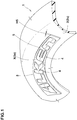
- a tyre 1 in this embodiment is provided with one or more mark indicating portions 3 in at least one of sidewall portions 2.
- Each of the mark indicating portions 3 is provided with a reference surface (x) provided on a surface (2s) of a respective one of the sidewall portions 2 and one or more marks 4 formed on the reference surface (x).
- each of the mark indicating portions 3 is provided with a base portion 5 which projects stepwise from the surface (2s) of a respective one of the sidewall portions 2 at a constant height (H5) (that is, a top surface of the base portion is not inclined with respect to the surface (2s)) and a surface (5s) of the base portion 5 forms the reference surface (x).
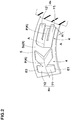
- Each of the marks 4 is a letter, a symbol, a figure, and the like for representing the manufacturer name, brand name, size, and the like of the tyre, and in this embodiment, a case is shown in which a brand name consisting of a plurality of the marks 4 is formed on the reference surface (x).
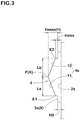
- a surface (4s) of each of the marks 4 includes a first inclined surface portion 11 disposed inward in a tyre radial direction and a second inclined surface portion 12 arranged outwardly in the tyre radial direction.
- the first inclined surface portion 11 is inclined such that a height (H) thereof from the reference surface (x) increases radially outwardly from an inner end (E1) in the tyre radial direction of the surface (4s).
- the second inclined surface portion 12 is inclined such that the height (H) thereof from the reference surface (x) increases radially inwardly from an outer end (E2) in the tyre radial direction of the surface (4s).
- the ridge line (K) is curved in an arc shape with a tyre axis as a center thereof.
- the ridge lines (K) of the plurality of the marks 4 which is arranged within the same mark indicating portion 3 are positioned on one circumferential line around the tyre axis.
- the surface (4s) of each of the marks 4 has the first and the second inclined surface portions 11 and 12 which are inclined in opposite directions, therefore, a change is given to appearance of the marks 4, thereby, it is possible that the design is improved. Further, a manner of reflection of light is different between the first inclined surface portion 11 and the second inclined surface portion 12, therefore, it is possible that stereoscopic effect of the marks 4 is emphasized while an increase in weight and air resistance is suppressed. Furthermore, there is a large difference in contrast depending on the viewing direction, therefore, it is possible that the legibility is improved by synergistic effect of these.
- a length (La) in the tyre radial direction of the first inclined surface portion 11 is in the range of from 0.8 to 1.2 times a length (Lb) in the tyre radial direction of the second inclined surface portion 12. If the above range is not satisfied, the effect described above tends to be decreased.
- a maximum height (Hmax) of the surface (4s) of each of the marks 4 from the reference surface (x) is larger than the height (H5) of the base portion 5 from the surface (2s) of each of the sidewall portions 2 from a point of view of the legibility.
- a minimum height (Hmin) of the surface (4s) of each of the marks 4 from the reference surface (x) is not more than the height (H5) of the base portion 5 from a point of view of suppressing an increase in air resistance.
- a middle surface portion (not shown) having a small width and parallel to the reference surface (x) is interposed between the first inclined surface portion 11 and the second inclined surface portion 12, for example.
- a width in the tyre radial direction of the middle surface portion is not more than 0.2 times a length in the tyre radial direction of the entire surface (4s).
- each of the first and the second inclined surface portions 11 and 12 is a flat surface, however, they may be curved surfaces extending in a curved manner in an arc shape in the tyre radial direction, for example.
- each of the mark indicating portions 3 as shown in Figs. 4A and 4B , it is preferred that a surface (S) which is either the reference surface (x) or the surface (4s) of each of the marks 4 is provided with a plurality of small protruding portions 15 each protruding from the surface (S).
- a case where each of the small protruding portions 15 is a truncated conical protrusion 16 having a smaller diameter on a side of an upper end thereof is shown.
- each of the truncated conical protrusions 16 has a maximum diameter (D1) in the range of from 50 to 1000 micro meters and a protruding height (H1) from the surface (S) in the range of from 50 to 1000 micro meters, and that a distance (L1) between centers of the small protruding portions 15 adjacent to each other is in the range of from 200 to 1000 micro meters.
- the truncated conical protrusions 16 configured as such irregularly reflect light and make the surface (S) (the reference surface (X) or the surface (4s) of the mark 4) look black. Thereby, it is possible that the contour shapes of the marks 4 are made clearer, therefore, it is possible that the legibility of the marks 4 is further improved.
- the truncated conical protrusions 16 are arranged in a grid pattern, but they may be arranged in a staggered pattern, or may be randomly arranged as long as the distance (L1) satisfies the above range.
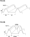
- Figs, 5A and 5B show another embodiment of the small protruding portions 15.
- each of the small protruding portions 15 is a rib-shaped protrusion 17 having a trapezoidal cross section with a thickness thereof decreasing toward an upper end thereof.
- the rib-shaped protrusions 17 can be arranged parallel to each other as shown in Fig, 5A , or they can be arranged so as not to be parallel to each other (non-parallel) as shown in Fig. 5B .
- each of the rib-shaped protrusions 17 has a maximum thickness (D2) in the range of from 20 to 1000 micro meters and a protruding height (H2) in the range of from 200 to 500 micro meters, and that a distance (L2) between the rib-shaped protrusions 17 adjacent to each other is in the range of from 10 to 800 micro meters. Note that in a case where the rib-shaped protrusions 17 are arranged in the non-parallel manner, it is preferred that an average value of a maximum value (L2max) and a minimum value (L2min) of the distance (L2) is in the range of from 10 to 800 micro meters.
- the rib-shaped protrusion 17 irregularly reflect light and make the surface (S) (the reference surface (x) or the surface (4s) of the mark 4) look black. Thereby, it is possible that the contour shapes of the marks 4 are made clearer, therefore, it is possible that the legibility of the marks 4 is further improved.
- each of the mark indicating portions 3 it is possible that the marks 4 are directly formed on the surface (2s) of a respective one of the sidewall portions 2 without having the base portion 5 formed thereon.
- the surface (2s) of the sidewall portion 2 forms the reference surface (x).
- the surface (2s) of each of the sidewall portions 2 is provided with a rib and the like having a small height and surrounding each of the mark indicating portions 3.
- Tyres provided with the mark indicating portions on the surfaces of the sidewall portions were made by way of test according to the specifications listed in Table 1, and then the legibility of the marks was compared.
- the height (H5) of the base portion was the same for all of the test tyres, and the height (H) (the maximum height (Hmax) if the surface of each of the marks was inclined) of each of the marks from the surface (the reference surface (x)) of the base portion was the same for all of the test tyres.
- each of the marks had a constant height from the base portion.
- the small protruding portions were formed on the surfaces of the marks.
- the small protruding portions were the truncated conical protrusions each having the maximum diameter (D1) of 320 micro meters and the protruding height (H1) of 500 micro meters, and the distance (L1) was 400 micro meters.
- the small protruding portions were the rib-shaped protrusions each having the maximum thickness (D2) of 160 micro meters and the protruding height (H2) of 200 micro meters, and the distance (L2) was 200 micro meters.
Abstract
Description
- The present invention relates to a tyre having improved legibility of a mark provided on a sidewall portion.
- On a surface of at least one of the sidewall portions of the tyre, one or marks which are letters, symbols, and the like indicating the manufacturer name, brand name, size, and the like of the tyre are formed. And in order to improve the legibility of the marks, for example, the marks are formed to be one step higher than the surface of the sidewall portion, and ridges are provided on the surfaces of the marks (for example, see Japanese Unexamined Patent Application Publication No.
H9-86106 - However, conventional marks have a constant height, therefore, even when a ridge is formed on the surface thereof, they have monotonous appearance and little change in contrast. Thereby, the legibility cannot be sufficiently improved.
- An object of the present invention is to provide a tyre capable of improving design by providing a change in the appearance of the marks and capable of improving the legibility of the marks by giving contrast between the surfaces of the marks and their reference surface.
- In one aspect of the present invention, a tyre comprises a sidewall portion provided with a mark indicating portion having one or more marks, wherein the mark indicating portion comprises a reference surface provided on a surface of the sidewall portion and the marks formed on the reference surface, and a surface of the or each mark includes a first inclined surface portion having a height from the reference surface increasing outwardly in a tyre radial direction from an inner end thereof in the tyre radial direction, and a second inclined surface portion having a height from the reference surface increasing inwardly in the tyre radial direction from an outer end thereof in the tyre radial direction.
- In another aspect of the invention, it is preferred that a length (La) in the tyre radial direction of the first inclined surface portion is in a range of from 0.8 to 1.2 times a length (Lb) in the tyre radial direction of the second inclined surface portion.
- In another aspect of the invention, it is preferred that in the mark indicating portion, either the reference surface or the surface of the or each mark is provided with a plurality of small protruding portions.
- In another aspect of the invention, it is preferred that each of the small protruding portions is a truncated conical protrusion having a smaller diameter on a side of an upper end thereof.
- In another aspect of the invention, it is preferred that each of the truncated conical protrusions has a maximum diameter in a range of from 50 to 1000 micro meters and a protruding height in a range of from 50 to 1000 micro meters, and a distance between centers of the truncated conical protrusions adjacent to each other is in a range of from 200 to 1000 micro meters.
- In another aspect of the invention, it is preferred that each of the small protruding portions is a rib-shaped protrusion having a trapezoidal cross section with a thickness thereof decreasing toward an upper end thereof, and the rib-shaped protrusions are arranged parallel to each other or in a non-parallel manner.
- In another aspect of the invention, it is preferred that each of the rib-shaped protrusions has a maximum thickness in a range of from 20 to 1000 micro meters and a protruding height in a range of from 200 to 500 micro meters, and a distance between the rib-shaped protrusions adjacent to each other is in a range of from 10 to 800 micro meters.
- In another aspect of the invention, it is preferred that the mark indicating portion is provided with a base portion projecting from the surface of the sidewall portion at a constant height, and a surface of the base portion forms the reference surface.
- In another aspect of the invention, it is preferred that a maximum height of the surface of the or each mark from the reference surface is larger than the height of the base portion from the surface of the sidewall portion.
-
-
Fig. 1 is a partial perspective view of a tyre according to an embodiment of the present invention. -
Fig. 2 is an enlarged partial perspective view of marks. -
Fig. 3 is an enlarged cross-sectional view of one of the marks taken along A-A line ofFig. 2 . -
Fig. 4A is a partial plan view showing an arrangement of small protruding portions formed as truncated conical protrusions. -
Fig. 4B is a cross-sectional view of the truncated conical protrusions. -
Fig. 5A is a partial perspective view showing an arrangement and cross sections of the small protruding portions formed as rib-shaped protrusions. -
Fig. 5B is a partial perspective view showing another arrangement and the cross sections of the small protruding portions formed as the rib-shaped protrusions. - An embodiment of the present invention will now be described below in detail.
- As shown in
Fig. 1 , a tyre 1 in this embodiment is provided with one or moremark indicating portions 3 in at least one ofsidewall portions 2. - Each of the
mark indicating portions 3 is provided with a reference surface (x) provided on a surface (2s) of a respective one of thesidewall portions 2 and one ormore marks 4 formed on the reference surface (x). In this embodiment, each of themark indicating portions 3 is provided with abase portion 5 which projects stepwise from the surface (2s) of a respective one of thesidewall portions 2 at a constant height (H5) (that is, a top surface of the base portion is not inclined with respect to the surface (2s)) and a surface (5s) of thebase portion 5 forms the reference surface (x). - Each of the
marks 4 is a letter, a symbol, a figure, and the like for representing the manufacturer name, brand name, size, and the like of the tyre, and in this embodiment, a case is shown in which a brand name consisting of a plurality of themarks 4 is formed on the reference surface (x). - As shown in
Figs. 2 and3 , a surface (4s) of each of themarks 4 includes a firstinclined surface portion 11 disposed inward in a tyre radial direction and a secondinclined surface portion 12 arranged outwardly in the tyre radial direction. - The first
inclined surface portion 11 is inclined such that a height (H) thereof from the reference surface (x) increases radially outwardly from an inner end (E1) in the tyre radial direction of the surface (4s). The secondinclined surface portion 12 is inclined such that the height (H) thereof from the reference surface (x) increases radially inwardly from an outer end (E2) in the tyre radial direction of the surface (4s). - In this example, a case in which the surface (4s) of each of the
marks 4 is formed by the first and the secondinclined surface portions inclined surface portion 11 and the secondinclined surface portion 12 intersect. - In this embodiment, the ridge line (K) is curved in an arc shape with a tyre axis as a center thereof. In particular, it is preferred that the ridge lines (K) of the plurality of the
marks 4 which is arranged within the samemark indicating portion 3 are positioned on one circumferential line around the tyre axis. - As described above, the surface (4s) of each of the
marks 4 has the first and the secondinclined surface portions marks 4, thereby, it is possible that the design is improved. Further, a manner of reflection of light is different between the firstinclined surface portion 11 and the secondinclined surface portion 12, therefore, it is possible that stereoscopic effect of themarks 4 is emphasized while an increase in weight and air resistance is suppressed. Furthermore, there is a large difference in contrast depending on the viewing direction, therefore, it is possible that the legibility is improved by synergistic effect of these. - As shown in
Fig. 3 , it is preferred that a length (La) in the tyre radial direction of the firstinclined surface portion 11 is in the range of from 0.8 to 1.2 times a length (Lb) in the tyre radial direction of the secondinclined surface portion 12. If the above range is not satisfied, the effect described above tends to be decreased. - It is preferred that a maximum height (Hmax) of the surface (4s) of each of the
marks 4 from the reference surface (x) is larger than the height (H5) of thebase portion 5 from the surface (2s) of each of thesidewall portions 2 from a point of view of the legibility. Note that it is preferred that a minimum height (Hmin) of the surface (4s) of each of themarks 4 from the reference surface (x) is not more than the height (H5) of thebase portion 5 from a point of view of suppressing an increase in air resistance. - It is also possible that a middle surface portion (not shown) having a small width and parallel to the reference surface (x) is interposed between the first
inclined surface portion 11 and the secondinclined surface portion 12, for example. In this case, it is preferred that a width in the tyre radial direction of the middle surface portion is not more than 0.2 times a length in the tyre radial direction of the entire surface (4s). - Further, it is preferred that each of the first and the second
inclined surface portions - Further, in each of the
mark indicating portions 3, as shown inFigs. 4A and 4B , it is preferred that a surface (S) which is either the reference surface (x) or the surface (4s) of each of themarks 4 is provided with a plurality of small protrudingportions 15 each protruding from the surface (S). In this embodiment, a case where each of the smallprotruding portions 15 is a truncatedconical protrusion 16 having a smaller diameter on a side of an upper end thereof is shown. It is preferred that each of the truncatedconical protrusions 16 has a maximum diameter (D1) in the range of from 50 to 1000 micro meters and a protruding height (H1) from the surface (S) in the range of from 50 to 1000 micro meters, and that a distance (L1) between centers of the small protrudingportions 15 adjacent to each other is in the range of from 200 to 1000 micro meters. - It is possible that the truncated
conical protrusions 16 configured as such irregularly reflect light and make the surface (S) (the reference surface (X) or the surface (4s) of the mark 4) look black. Thereby, it is possible that the contour shapes of themarks 4 are made clearer, therefore, it is possible that the legibility of themarks 4 is further improved. As a result of research by the present inventor, when the maximum diameter (D1) and the protruding height (H1) of each of the truncatedconical protrusions 16, and the distance (L1) of the truncatedconical protrusions 16 are outside the above ranges, the surface (S) looks whitish due to the reflection of light, therefore, the contrast difference between themarks 4 and the reference surface (x) tends to be decreased. Note that by configuring each of the small protrudingportions 15 to have a truncated cone shape, it is possible that the reflection of light is further suppressed while the strength is increased as compared with a cylindrical shape. - In this embodiment, a case is shown in which the truncated
conical protrusions 16 are arranged in a grid pattern, but they may be arranged in a staggered pattern, or may be randomly arranged as long as the distance (L1) satisfies the above range. -
Figs, 5A and 5B show another embodiment of the small protrudingportions 15. In this embodiment, a case is shown where each of the small protrudingportions 15 is a rib-shaped protrusion 17 having a trapezoidal cross section with a thickness thereof decreasing toward an upper end thereof. The rib-shapedprotrusions 17 can be arranged parallel to each other as shown inFig, 5A , or they can be arranged so as not to be parallel to each other (non-parallel) as shown inFig. 5B . It is preferred that each of the rib-shapedprotrusions 17 has a maximum thickness (D2) in the range of from 20 to 1000 micro meters and a protruding height (H2) in the range of from 200 to 500 micro meters, and that a distance (L2) between the rib-shapedprotrusions 17 adjacent to each other is in the range of from 10 to 800 micro meters. Note that in a case where the rib-shapedprotrusions 17 are arranged in the non-parallel manner, it is preferred that an average value of a maximum value (L2max) and a minimum value (L2min) of the distance (L2) is in the range of from 10 to 800 micro meters. - As is the case with the truncated
conical protrusions 16, it is possible that the rib-shapedprotrusion 17 irregularly reflect light and make the surface (S) (the reference surface (x) or the surface (4s) of the mark 4) look black. Thereby, it is possible that the contour shapes of themarks 4 are made clearer, therefore, it is possible that the legibility of themarks 4 is further improved. As a result of research by the present inventor, when the maximum thickness (D2) and the protruding height (H2) of each of the rib-shapedprotrusions 17, and the distance (L2) of the rib-shapedprotrusions 17 are outside the above ranges, the surface (S) looks whitish due to the reflection of light, therefore, the contrast difference between themarks 4 and the reference surface (x) tends to be decreased. Note that, from a point of view of the contrast, it is more preferred that the rib-shapedprotrusions 17 are arranged in the non-parallel manner. - In each of the
mark indicating portions 3, it is possible that themarks 4 are directly formed on the surface (2s) of a respective one of thesidewall portions 2 without having thebase portion 5 formed thereon. In this case, the surface (2s) of thesidewall portion 2 forms the reference surface (x). In this case, in order to distinguish themark indicating portions 3 from other portions, it is preferred that the surface (2s) of each of thesidewall portions 2 is provided with a rib and the like having a small height and surrounding each of themark indicating portions 3. - while detailed description has been made of the tyre as especially preferred embodiments of the present invention, the present invention can be embodied in various forms without being limited to the illustrated embodiments.
- Tyres provided with the mark indicating portions on the surfaces of the sidewall portions were made by way of test according to the specifications listed in Table 1, and then the legibility of the marks was compared. The height (H5) of the base portion was the same for all of the test tyres, and the height (H) (the maximum height (Hmax) if the surface of each of the marks was inclined) of each of the marks from the surface (the reference surface (x)) of the base portion was the same for all of the test tyres.
- In Reference 1, each of the marks had a constant height from the base portion. In Examples 2 to 5, the small protruding portions were formed on the surfaces of the marks. In the Examples 2 and 3, the small protruding portions were the truncated conical protrusions each having the maximum diameter (D1) of 320 micro meters and the protruding height (H1) of 500 micro meters, and the distance (L1) was 400 micro meters. In the Examples 4 and 5, the small protruding portions were the rib-shaped protrusions each having the maximum thickness (D2) of 160 micro meters and the protruding height (H2) of 200 micro meters, and the distance (L2) was 200 micro meters.
- The legibility was evaluated by a visual observation and the evaluation is indicated by an index based on the Reference 1 being 100, wherein a larger numerical value is better.
Table 1. Ref.1 EX.1 Ex.2 Ex.3 Ex.4 Ex.5 <Mark indicating portion > Base portion Present Absent Present Mark Present • First inclined surface portion Absent Present • Second inclined surface portion Absent Present • Ratio of Length (La) and Length (Lb) - 1 • Magnitude relation between Maximum height (Hmax) and Height (H5) Hmax > H5 - Hmax > H5 Small protruding portion Absent Absent Truncated conical protrusion Truncated conical protrusion Rib-shaped protrusion (parallel) Rib-shaped protrusion (non-parallel) Legibility 100 108 113 105 130 135 - As shown in Table 1, it was confirmed that the tyres as the Examples showed excellent legibility of the marks.
Claims (9)
- A tyre comprising a sidewall portion provided with a mark indicating portion having one or more marks, wherein
the mark indicating portion comprises a reference surface provided on a surface of the sidewall portion and the one or more marks formed on the reference surface, and
a surface of the or each mark includes a first inclined surface portion having a height from the reference surface increasing outwardly in a tyre radial direction from an inner end thereof in the tyre radial direction, and a second inclined surface portion having a height from the reference surface increasing inwardly in the tyre radial direction from an outer end thereof in the tyre radial direction. - The tyre according to claim 1, wherein
a length (La) in the tyre radial direction of the first inclined surface portion is in a range of from 0.8 to 1.2 times a length (Lb) in the tyre radial direction of the second inclined surface portion. - The tyre according to claim 1 or 2, wherein
in the mark indicating portion, either the reference surface or the surface of the or each mark is provided with a plurality of small protruding portions. - The tyre according to claim 3, wherein
each of the small protruding portions is a truncated conical protrusion having a smaller diameter on a side of an upper end thereof. - The tyre according to claim 4, wherein
each of the truncated conical protrusions has a maximum diameter in a range of from 50 to 1000 micro meters and a protruding height in a range of from 50 to 1000 micro meters, and
a distance between centers of the truncated conical protrusions adjacent to each other is in a range of from 200 to 1000 micro meters. - The tyre according to claim 3, wherein
each of the small protruding portions is a rib-shaped protrusion having a trapezoidal cross section with a thickness thereof decreasing toward an upper end thereof, and
the rib-shaped protrusions are arranged parallel to each other or in a non-parallel manner. - The tyre according to claim 6, wherein
each of the rib-shaped protrusions has a maximum thickness in a range of from 20 to 1000 micro meters and a protruding height in a range of from 200 to 500 micro meters, and
a distance between the rib-shaped protrusions adjacent to each other is in a range of from 10 to 800 micro meters. - The tyre according to any one of claims 1 to 7, wherein
the mark indicating portion is provided with a base portion projecting from the surface of the sidewall portion at a constant height, and
a surface of the base portion forms the reference surface. - The tyre according to claim 8, wherein
a maximum height of the surface of the or each mark from the reference surface is larger than the height of the base portion from the surface of the sidewall portion.
Applications Claiming Priority (1)
| Application Number | Priority Date | Filing Date | Title |
|---|---|---|---|
| JP2018034039A JP7069828B2 (en) | 2018-02-28 | 2018-02-28 | tire |
Publications (2)
| Publication Number | Publication Date |
|---|---|
| EP3533633A1 true EP3533633A1 (en) | 2019-09-04 |
| EP3533633B1 EP3533633B1 (en) | 2020-09-16 |
Family
ID=65011876
Family Applications (1)
| Application Number | Title | Priority Date | Filing Date |
|---|---|---|---|
| EP19150901.7A Active EP3533633B1 (en) | 2018-02-28 | 2019-01-09 | Tyre |
Country Status (3)
| Country | Link |
|---|---|
| US (1) | US11077722B2 (en) |
| EP (1) | EP3533633B1 (en) |
| JP (1) | JP7069828B2 (en) |
Cited By (1)
| Publication number | Priority date | Publication date | Assignee | Title |
|---|---|---|---|---|
| EP3666555A1 (en) * | 2018-12-11 | 2020-06-17 | Sumitomo Rubber Industries, Ltd. | Tire |
Families Citing this family (5)
| Publication number | Priority date | Publication date | Assignee | Title |
|---|---|---|---|---|
| USD1000372S1 (en) * | 2021-04-19 | 2023-10-03 | Continental Reifen Deutschland Gmbh | Sidewall of a tire with graphic symbol |
| USD999722S1 (en) * | 2021-04-19 | 2023-09-26 | Continental Reifen Deutschland Gmbh | Sidewall of a tire with graphic symbol |
| USD1001726S1 (en) * | 2021-04-19 | 2023-10-17 | Continental Reifen Deustschland Gmbh | Sidewall of a tire with graphic symbol |
| USD1000371S1 (en) * | 2021-04-19 | 2023-10-03 | Continental Reifen Deutschland Gmbh | Sidewall of a tire with graphic symbol |
| JP2023113406A (en) * | 2022-02-03 | 2023-08-16 | Toyo Tire株式会社 | pneumatic tire |
Citations (7)
| Publication number | Priority date | Publication date | Assignee | Title |
|---|---|---|---|---|
| EP0490247A1 (en) * | 1990-12-10 | 1992-06-17 | The Uniroyal Goodrich Tire Company | Character for a tire |
| JPH0986106A (en) | 1995-09-28 | 1997-03-31 | Sumitomo Rubber Ind Ltd | Pneumatic tire |
| JP2007083604A (en) * | 2005-09-22 | 2007-04-05 | Yokohama Rubber Co Ltd:The | Mold for vulcanizing tire, method for manufacturing pnneumatic tire, and pnuematic tire |
| JP2008265502A (en) * | 2007-04-19 | 2008-11-06 | Yokohama Rubber Co Ltd:The | Pneumatic tire |
| JP2008273505A (en) * | 2007-04-05 | 2008-11-13 | Toyo Tire & Rubber Co Ltd | Pneumatic tire |
| US20120227879A1 (en) * | 2009-09-28 | 2012-09-13 | Michelin Recherche Et Technique S.A. | High-contrast tire pattern and method for producing same |
| US20130263993A1 (en) * | 2012-04-04 | 2013-10-10 | The Yokohama Rubber Co., Ltd. | Pneumatic Tire |
Family Cites Families (8)
| Publication number | Priority date | Publication date | Assignee | Title |
|---|---|---|---|---|
| JP3652809B2 (en) * | 1996-09-13 | 2005-05-25 | 株式会社ブリヂストン | Pneumatic tire |
| JP3733054B2 (en) | 2001-11-08 | 2006-01-11 | 住友ゴム工業株式会社 | tire |
| US7232498B2 (en) * | 2004-08-13 | 2007-06-19 | The Goodyear Tire & Rubber Company | Tire with raised indicia |
| JP2006224704A (en) | 2005-02-15 | 2006-08-31 | Bridgestone Corp | Pneumatic tire |
| US20080283169A1 (en) * | 2007-02-22 | 2008-11-20 | Toyo Tire & Rubber Co., Ltd. | Pneumatic Tire |
| JP5160345B2 (en) * | 2008-08-26 | 2013-03-13 | 東洋ゴム工業株式会社 | Pneumatic tire |
| US20190202244A1 (en) * | 2016-05-02 | 2019-07-04 | The Yokohama Rubber Co., Ltd. | Rubber Member, Tire, and Method of Manufacturing Rubber Member |
| JP6747932B2 (en) * | 2016-10-11 | 2020-08-26 | Toyo Tire株式会社 | Pneumatic tire |
-
2018
- 2018-02-28 JP JP2018034039A patent/JP7069828B2/en active Active
-
2019
- 2019-01-09 EP EP19150901.7A patent/EP3533633B1/en active Active
- 2019-02-14 US US16/275,443 patent/US11077722B2/en active Active
Patent Citations (7)
| Publication number | Priority date | Publication date | Assignee | Title |
|---|---|---|---|---|
| EP0490247A1 (en) * | 1990-12-10 | 1992-06-17 | The Uniroyal Goodrich Tire Company | Character for a tire |
| JPH0986106A (en) | 1995-09-28 | 1997-03-31 | Sumitomo Rubber Ind Ltd | Pneumatic tire |
| JP2007083604A (en) * | 2005-09-22 | 2007-04-05 | Yokohama Rubber Co Ltd:The | Mold for vulcanizing tire, method for manufacturing pnneumatic tire, and pnuematic tire |
| JP2008273505A (en) * | 2007-04-05 | 2008-11-13 | Toyo Tire & Rubber Co Ltd | Pneumatic tire |
| JP2008265502A (en) * | 2007-04-19 | 2008-11-06 | Yokohama Rubber Co Ltd:The | Pneumatic tire |
| US20120227879A1 (en) * | 2009-09-28 | 2012-09-13 | Michelin Recherche Et Technique S.A. | High-contrast tire pattern and method for producing same |
| US20130263993A1 (en) * | 2012-04-04 | 2013-10-10 | The Yokohama Rubber Co., Ltd. | Pneumatic Tire |
Cited By (1)
| Publication number | Priority date | Publication date | Assignee | Title |
|---|---|---|---|---|
| EP3666555A1 (en) * | 2018-12-11 | 2020-06-17 | Sumitomo Rubber Industries, Ltd. | Tire |
Also Published As
| Publication number | Publication date |
|---|---|
| US11077722B2 (en) | 2021-08-03 |
| EP3533633B1 (en) | 2020-09-16 |
| JP7069828B2 (en) | 2022-05-18 |
| US20190263193A1 (en) | 2019-08-29 |
| JP2019147496A (en) | 2019-09-05 |
Similar Documents
| Publication | Publication Date | Title |
|---|---|---|
| EP3533633B1 (en) | Tyre | |
| EP3546251B1 (en) | Tyre | |
| CN108602397B (en) | Tyre for vehicle wheels | |
| EP2781376A1 (en) | Pneumatic tire | |
| EP3489040A1 (en) | Tire | |
| EP3533638B1 (en) | Tyre | |
| EP3511180B1 (en) | Tyre | |
| EP3533635B1 (en) | Tyre | |
| EP3533636B1 (en) | Tyre | |
| EP3533634B1 (en) | Tyre | |
| JPWO2016121345A1 (en) | Pneumatic tire | |
| EP3533637B1 (en) | Tyre | |
| EP3666555B1 (en) | Tire | |
| EP3546252B1 (en) | Tyre |
Legal Events
| Date | Code | Title | Description |
|---|---|---|---|
| PUAI | Public reference made under article 153(3) epc to a published international application that has entered the european phase |
Free format text: ORIGINAL CODE: 0009012 |
|
| STAA | Information on the status of an ep patent application or granted ep patent |
Free format text: STATUS: THE APPLICATION HAS BEEN PUBLISHED |
|
| AK | Designated contracting states |
Kind code of ref document: A1 Designated state(s): AL AT BE BG CH CY CZ DE DK EE ES FI FR GB GR HR HU IE IS IT LI LT LU LV MC MK MT NL NO PL PT RO RS SE SI SK SM TR |
|
| AX | Request for extension of the european patent |
Extension state: BA ME |
|
| STAA | Information on the status of an ep patent application or granted ep patent |
Free format text: STATUS: REQUEST FOR EXAMINATION WAS MADE |
|
| 17P | Request for examination filed |
Effective date: 20200226 |
|
| RBV | Designated contracting states (corrected) |
Designated state(s): AL AT BE BG CH CY CZ DE DK EE ES FI FR GB GR HR HU IE IS IT LI LT LU LV MC MK MT NL NO PL PT RO RS SE SI SK SM TR |
|
| GRAP | Despatch of communication of intention to grant a patent |
Free format text: ORIGINAL CODE: EPIDOSNIGR1 |
|
| STAA | Information on the status of an ep patent application or granted ep patent |
Free format text: STATUS: GRANT OF PATENT IS INTENDED |
|
| INTG | Intention to grant announced |
Effective date: 20200423 |
|
| GRAS | Grant fee paid |
Free format text: ORIGINAL CODE: EPIDOSNIGR3 |
|
| GRAA | (expected) grant |
Free format text: ORIGINAL CODE: 0009210 |
|
| STAA | Information on the status of an ep patent application or granted ep patent |
Free format text: STATUS: THE PATENT HAS BEEN GRANTED |
|
| AK | Designated contracting states |
Kind code of ref document: B1 Designated state(s): AL AT BE BG CH CY CZ DE DK EE ES FI FR GB GR HR HU IE IS IT LI LT LU LV MC MK MT NL NO PL PT RO RS SE SI SK SM TR |
|
| REG | Reference to a national code |
Ref country code: GB Ref legal event code: FG4D |
|
| REG | Reference to a national code |
Ref country code: CH Ref legal event code: EP |
|
| REG | Reference to a national code |
Ref country code: DE Ref legal event code: R096 Ref document number: 602019000653 Country of ref document: DE |
|
| REG | Reference to a national code |
Ref country code: IE Ref legal event code: FG4D |
|
| REG | Reference to a national code |
Ref country code: AT Ref legal event code: REF Ref document number: 1313830 Country of ref document: AT Kind code of ref document: T Effective date: 20201015 |
|
| PG25 | Lapsed in a contracting state [announced via postgrant information from national office to epo] |
Ref country code: FI Free format text: LAPSE BECAUSE OF FAILURE TO SUBMIT A TRANSLATION OF THE DESCRIPTION OR TO PAY THE FEE WITHIN THE PRESCRIBED TIME-LIMIT Effective date: 20200916 Ref country code: HR Free format text: LAPSE BECAUSE OF FAILURE TO SUBMIT A TRANSLATION OF THE DESCRIPTION OR TO PAY THE FEE WITHIN THE PRESCRIBED TIME-LIMIT Effective date: 20200916 Ref country code: SE Free format text: LAPSE BECAUSE OF FAILURE TO SUBMIT A TRANSLATION OF THE DESCRIPTION OR TO PAY THE FEE WITHIN THE PRESCRIBED TIME-LIMIT Effective date: 20200916 Ref country code: GR Free format text: LAPSE BECAUSE OF FAILURE TO SUBMIT A TRANSLATION OF THE DESCRIPTION OR TO PAY THE FEE WITHIN THE PRESCRIBED TIME-LIMIT Effective date: 20201217 Ref country code: NO Free format text: LAPSE BECAUSE OF FAILURE TO SUBMIT A TRANSLATION OF THE DESCRIPTION OR TO PAY THE FEE WITHIN THE PRESCRIBED TIME-LIMIT Effective date: 20201216 Ref country code: BG Free format text: LAPSE BECAUSE OF FAILURE TO SUBMIT A TRANSLATION OF THE DESCRIPTION OR TO PAY THE FEE WITHIN THE PRESCRIBED TIME-LIMIT Effective date: 20201216 |
|
| REG | Reference to a national code |
Ref country code: AT Ref legal event code: MK05 Ref document number: 1313830 Country of ref document: AT Kind code of ref document: T Effective date: 20200916 |
|
| REG | Reference to a national code |
Ref country code: NL Ref legal event code: MP Effective date: 20200916 |
|
| PG25 | Lapsed in a contracting state [announced via postgrant information from national office to epo] |
Ref country code: RS Free format text: LAPSE BECAUSE OF FAILURE TO SUBMIT A TRANSLATION OF THE DESCRIPTION OR TO PAY THE FEE WITHIN THE PRESCRIBED TIME-LIMIT Effective date: 20200916 Ref country code: LV Free format text: LAPSE BECAUSE OF FAILURE TO SUBMIT A TRANSLATION OF THE DESCRIPTION OR TO PAY THE FEE WITHIN THE PRESCRIBED TIME-LIMIT Effective date: 20200916 |
|
| REG | Reference to a national code |
Ref country code: LT Ref legal event code: MG4D |
|
| PG25 | Lapsed in a contracting state [announced via postgrant information from national office to epo] |
Ref country code: EE Free format text: LAPSE BECAUSE OF FAILURE TO SUBMIT A TRANSLATION OF THE DESCRIPTION OR TO PAY THE FEE WITHIN THE PRESCRIBED TIME-LIMIT Effective date: 20200916 Ref country code: PT Free format text: LAPSE BECAUSE OF FAILURE TO SUBMIT A TRANSLATION OF THE DESCRIPTION OR TO PAY THE FEE WITHIN THE PRESCRIBED TIME-LIMIT Effective date: 20210118 Ref country code: RO Free format text: LAPSE BECAUSE OF FAILURE TO SUBMIT A TRANSLATION OF THE DESCRIPTION OR TO PAY THE FEE WITHIN THE PRESCRIBED TIME-LIMIT Effective date: 20200916 Ref country code: CZ Free format text: LAPSE BECAUSE OF FAILURE TO SUBMIT A TRANSLATION OF THE DESCRIPTION OR TO PAY THE FEE WITHIN THE PRESCRIBED TIME-LIMIT Effective date: 20200916 Ref country code: LT Free format text: LAPSE BECAUSE OF FAILURE TO SUBMIT A TRANSLATION OF THE DESCRIPTION OR TO PAY THE FEE WITHIN THE PRESCRIBED TIME-LIMIT Effective date: 20200916 Ref country code: SM Free format text: LAPSE BECAUSE OF FAILURE TO SUBMIT A TRANSLATION OF THE DESCRIPTION OR TO PAY THE FEE WITHIN THE PRESCRIBED TIME-LIMIT Effective date: 20200916 |
|
| PG25 | Lapsed in a contracting state [announced via postgrant information from national office to epo] |
Ref country code: ES Free format text: LAPSE BECAUSE OF FAILURE TO SUBMIT A TRANSLATION OF THE DESCRIPTION OR TO PAY THE FEE WITHIN THE PRESCRIBED TIME-LIMIT Effective date: 20200916 Ref country code: AL Free format text: LAPSE BECAUSE OF FAILURE TO SUBMIT A TRANSLATION OF THE DESCRIPTION OR TO PAY THE FEE WITHIN THE PRESCRIBED TIME-LIMIT Effective date: 20200916 Ref country code: AT Free format text: LAPSE BECAUSE OF FAILURE TO SUBMIT A TRANSLATION OF THE DESCRIPTION OR TO PAY THE FEE WITHIN THE PRESCRIBED TIME-LIMIT Effective date: 20200916 Ref country code: IS Free format text: LAPSE BECAUSE OF FAILURE TO SUBMIT A TRANSLATION OF THE DESCRIPTION OR TO PAY THE FEE WITHIN THE PRESCRIBED TIME-LIMIT Effective date: 20210116 Ref country code: PL Free format text: LAPSE BECAUSE OF FAILURE TO SUBMIT A TRANSLATION OF THE DESCRIPTION OR TO PAY THE FEE WITHIN THE PRESCRIBED TIME-LIMIT Effective date: 20200916 |
|
| REG | Reference to a national code |
Ref country code: DE Ref legal event code: R097 Ref document number: 602019000653 Country of ref document: DE |
|
| PG25 | Lapsed in a contracting state [announced via postgrant information from national office to epo] |
Ref country code: SK Free format text: LAPSE BECAUSE OF FAILURE TO SUBMIT A TRANSLATION OF THE DESCRIPTION OR TO PAY THE FEE WITHIN THE PRESCRIBED TIME-LIMIT Effective date: 20200916 |
|
| PLBE | No opposition filed within time limit |
Free format text: ORIGINAL CODE: 0009261 |
|
| STAA | Information on the status of an ep patent application or granted ep patent |
Free format text: STATUS: NO OPPOSITION FILED WITHIN TIME LIMIT |
|
| 26N | No opposition filed |
Effective date: 20210617 |
|
| PG25 | Lapsed in a contracting state [announced via postgrant information from national office to epo] |
Ref country code: MC Free format text: LAPSE BECAUSE OF FAILURE TO SUBMIT A TRANSLATION OF THE DESCRIPTION OR TO PAY THE FEE WITHIN THE PRESCRIBED TIME-LIMIT Effective date: 20200916 Ref country code: SI Free format text: LAPSE BECAUSE OF FAILURE TO SUBMIT A TRANSLATION OF THE DESCRIPTION OR TO PAY THE FEE WITHIN THE PRESCRIBED TIME-LIMIT Effective date: 20200916 Ref country code: DK Free format text: LAPSE BECAUSE OF FAILURE TO SUBMIT A TRANSLATION OF THE DESCRIPTION OR TO PAY THE FEE WITHIN THE PRESCRIBED TIME-LIMIT Effective date: 20200916 |
|
| PG25 | Lapsed in a contracting state [announced via postgrant information from national office to epo] |
Ref country code: LU Free format text: LAPSE BECAUSE OF NON-PAYMENT OF DUE FEES Effective date: 20210109 |
|
| REG | Reference to a national code |
Ref country code: BE Ref legal event code: MM Effective date: 20210131 |
|
| PG25 | Lapsed in a contracting state [announced via postgrant information from national office to epo] |
Ref country code: IT Free format text: LAPSE BECAUSE OF FAILURE TO SUBMIT A TRANSLATION OF THE DESCRIPTION OR TO PAY THE FEE WITHIN THE PRESCRIBED TIME-LIMIT Effective date: 20200916 |
|
| PG25 | Lapsed in a contracting state [announced via postgrant information from national office to epo] |
Ref country code: IE Free format text: LAPSE BECAUSE OF NON-PAYMENT OF DUE FEES Effective date: 20210109 |
|
| PG25 | Lapsed in a contracting state [announced via postgrant information from national office to epo] |
Ref country code: BE Free format text: LAPSE BECAUSE OF NON-PAYMENT OF DUE FEES Effective date: 20210131 |
|
| REG | Reference to a national code |
Ref country code: CH Ref legal event code: PL |
|
| PG25 | Lapsed in a contracting state [announced via postgrant information from national office to epo] |
Ref country code: LI Free format text: LAPSE BECAUSE OF NON-PAYMENT OF DUE FEES Effective date: 20220131 Ref country code: CH Free format text: LAPSE BECAUSE OF NON-PAYMENT OF DUE FEES Effective date: 20220131 |
|
| PGFP | Annual fee paid to national office [announced via postgrant information from national office to epo] |
Ref country code: DE Payment date: 20221130 Year of fee payment: 5 |
|
| P01 | Opt-out of the competence of the unified patent court (upc) registered |
Effective date: 20230510 |
|
| PG25 | Lapsed in a contracting state [announced via postgrant information from national office to epo] |
Ref country code: NL Free format text: LAPSE BECAUSE OF NON-PAYMENT OF DUE FEES Effective date: 20200923 Ref country code: CY Free format text: LAPSE BECAUSE OF FAILURE TO SUBMIT A TRANSLATION OF THE DESCRIPTION OR TO PAY THE FEE WITHIN THE PRESCRIBED TIME-LIMIT Effective date: 20200916 |
|
| PG25 | Lapsed in a contracting state [announced via postgrant information from national office to epo] |
Ref country code: HU Free format text: LAPSE BECAUSE OF FAILURE TO SUBMIT A TRANSLATION OF THE DESCRIPTION OR TO PAY THE FEE WITHIN THE PRESCRIBED TIME-LIMIT; INVALID AB INITIO Effective date: 20190109 |
|
| GBPC | Gb: european patent ceased through non-payment of renewal fee |
Effective date: 20230109 |
|
| PG25 | Lapsed in a contracting state [announced via postgrant information from national office to epo] |
Ref country code: GB Free format text: LAPSE BECAUSE OF NON-PAYMENT OF DUE FEES Effective date: 20230109 |
|
| PGFP | Annual fee paid to national office [announced via postgrant information from national office to epo] |
Ref country code: FR Payment date: 20231212 Year of fee payment: 6 |