EP3533540B1 - Verfahren zur herstellung eines rohrförmigen körpers mit reduzierter interner spannung unter verwendung von laser 3d-druck und rohrförmiger körper mit reduzierter interner spannung - Google Patents
Verfahren zur herstellung eines rohrförmigen körpers mit reduzierter interner spannung unter verwendung von laser 3d-druck und rohrförmiger körper mit reduzierter interner spannung Download PDFInfo
- Publication number
- EP3533540B1 EP3533540B1 EP19155874.1A EP19155874A EP3533540B1 EP 3533540 B1 EP3533540 B1 EP 3533540B1 EP 19155874 A EP19155874 A EP 19155874A EP 3533540 B1 EP3533540 B1 EP 3533540B1
- Authority
- EP
- European Patent Office
- Prior art keywords
- layer
- tubular body
- stiffening structure
- wall
- printing
- Prior art date
- Legal status (The legal status is an assumption and is not a legal conclusion. Google has not performed a legal analysis and makes no representation as to the accuracy of the status listed.)
- Active
Links
Images


Classifications
-
- B—PERFORMING OPERATIONS; TRANSPORTING
- B22—CASTING; POWDER METALLURGY
- B22F—WORKING METALLIC POWDER; MANUFACTURE OF ARTICLES FROM METALLIC POWDER; MAKING METALLIC POWDER; APPARATUS OR DEVICES SPECIALLY ADAPTED FOR METALLIC POWDER
- B22F5/00—Manufacture of workpieces or articles from metallic powder characterised by the special shape of the product
- B22F5/10—Manufacture of workpieces or articles from metallic powder characterised by the special shape of the product of articles with cavities or holes, not otherwise provided for in the preceding subgroups
- B22F5/106—Tube or ring forms
-
- B—PERFORMING OPERATIONS; TRANSPORTING
- B22—CASTING; POWDER METALLURGY
- B22F—WORKING METALLIC POWDER; MANUFACTURE OF ARTICLES FROM METALLIC POWDER; MAKING METALLIC POWDER; APPARATUS OR DEVICES SPECIALLY ADAPTED FOR METALLIC POWDER
- B22F5/00—Manufacture of workpieces or articles from metallic powder characterised by the special shape of the product
- B22F5/009—Manufacture of workpieces or articles from metallic powder characterised by the special shape of the product of turbine components other than turbine blades
-
- B—PERFORMING OPERATIONS; TRANSPORTING
- B22—CASTING; POWDER METALLURGY
- B22F—WORKING METALLIC POWDER; MANUFACTURE OF ARTICLES FROM METALLIC POWDER; MAKING METALLIC POWDER; APPARATUS OR DEVICES SPECIALLY ADAPTED FOR METALLIC POWDER
- B22F10/00—Additive manufacturing of workpieces or articles from metallic powder
- B22F10/20—Direct sintering or melting
- B22F10/28—Powder bed fusion, e.g. selective laser melting [SLM] or electron beam melting [EBM]
-
- B—PERFORMING OPERATIONS; TRANSPORTING
- B29—WORKING OF PLASTICS; WORKING OF SUBSTANCES IN A PLASTIC STATE IN GENERAL
- B29C—SHAPING OR JOINING OF PLASTICS; SHAPING OF MATERIAL IN A PLASTIC STATE, NOT OTHERWISE PROVIDED FOR; AFTER-TREATMENT OF THE SHAPED PRODUCTS, e.g. REPAIRING
- B29C64/00—Additive manufacturing, i.e. manufacturing of three-dimensional [3D] objects by additive deposition, additive agglomeration or additive layering, e.g. by 3D printing, stereolithography or selective laser sintering
- B29C64/10—Processes of additive manufacturing
- B29C64/141—Processes of additive manufacturing using only solid materials
- B29C64/153—Processes of additive manufacturing using only solid materials using layers of powder being selectively joined, e.g. by selective laser sintering or melting
-
- B—PERFORMING OPERATIONS; TRANSPORTING
- B29—WORKING OF PLASTICS; WORKING OF SUBSTANCES IN A PLASTIC STATE IN GENERAL
- B29D—PRODUCING PARTICULAR ARTICLES FROM PLASTICS OR FROM SUBSTANCES IN A PLASTIC STATE
- B29D23/00—Producing tubular articles
- B29D23/001—Pipes; Pipe joints
-
- B—PERFORMING OPERATIONS; TRANSPORTING
- B33—ADDITIVE MANUFACTURING TECHNOLOGY
- B33Y—ADDITIVE MANUFACTURING, i.e. MANUFACTURING OF THREE-DIMENSIONAL [3D] OBJECTS BY ADDITIVE DEPOSITION, ADDITIVE AGGLOMERATION OR ADDITIVE LAYERING, e.g. BY 3D PRINTING, STEREOLITHOGRAPHY OR SELECTIVE LASER SINTERING
- B33Y10/00—Processes of additive manufacturing
-
- B—PERFORMING OPERATIONS; TRANSPORTING
- B33—ADDITIVE MANUFACTURING TECHNOLOGY
- B33Y—ADDITIVE MANUFACTURING, i.e. MANUFACTURING OF THREE-DIMENSIONAL [3D] OBJECTS BY ADDITIVE DEPOSITION, ADDITIVE AGGLOMERATION OR ADDITIVE LAYERING, e.g. BY 3D PRINTING, STEREOLITHOGRAPHY OR SELECTIVE LASER SINTERING
- B33Y80/00—Products made by additive manufacturing
-
- F—MECHANICAL ENGINEERING; LIGHTING; HEATING; WEAPONS; BLASTING
- F02—COMBUSTION ENGINES; HOT-GAS OR COMBUSTION-PRODUCT ENGINE PLANTS
- F02C—GAS-TURBINE PLANTS; AIR INTAKES FOR JET-PROPULSION PLANTS; CONTROLLING FUEL SUPPLY IN AIR-BREATHING JET-PROPULSION PLANTS
- F02C7/00—Features, components parts, details or accessories, not provided for in, or of interest apart form groups F02C1/00 - F02C6/00; Air intakes for jet-propulsion plants
- F02C7/22—Fuel supply systems
- F02C7/222—Fuel flow conduits, e.g. manifolds
-
- F—MECHANICAL ENGINEERING; LIGHTING; HEATING; WEAPONS; BLASTING
- F16—ENGINEERING ELEMENTS AND UNITS; GENERAL MEASURES FOR PRODUCING AND MAINTAINING EFFECTIVE FUNCTIONING OF MACHINES OR INSTALLATIONS; THERMAL INSULATION IN GENERAL
- F16L—PIPES; JOINTS OR FITTINGS FOR PIPES; SUPPORTS FOR PIPES, CABLES OR PROTECTIVE TUBING; MEANS FOR THERMAL INSULATION IN GENERAL
- F16L9/00—Rigid pipes
- F16L9/02—Rigid pipes of metal
-
- F—MECHANICAL ENGINEERING; LIGHTING; HEATING; WEAPONS; BLASTING
- F16—ENGINEERING ELEMENTS AND UNITS; GENERAL MEASURES FOR PRODUCING AND MAINTAINING EFFECTIVE FUNCTIONING OF MACHINES OR INSTALLATIONS; THERMAL INSULATION IN GENERAL
- F16L—PIPES; JOINTS OR FITTINGS FOR PIPES; SUPPORTS FOR PIPES, CABLES OR PROTECTIVE TUBING; MEANS FOR THERMAL INSULATION IN GENERAL
- F16L9/00—Rigid pipes
- F16L9/12—Rigid pipes of plastics with or without reinforcement
- F16L9/127—Rigid pipes of plastics with or without reinforcement the walls consisting of a single layer
- F16L9/128—Reinforced pipes
-
- B—PERFORMING OPERATIONS; TRANSPORTING
- B22—CASTING; POWDER METALLURGY
- B22F—WORKING METALLIC POWDER; MANUFACTURE OF ARTICLES FROM METALLIC POWDER; MAKING METALLIC POWDER; APPARATUS OR DEVICES SPECIALLY ADAPTED FOR METALLIC POWDER
- B22F5/00—Manufacture of workpieces or articles from metallic powder characterised by the special shape of the product
- B22F2005/005—Article surface comprising protrusions
-
- B—PERFORMING OPERATIONS; TRANSPORTING
- B29—WORKING OF PLASTICS; WORKING OF SUBSTANCES IN A PLASTIC STATE IN GENERAL
- B29L—INDEXING SCHEME ASSOCIATED WITH SUBCLASS B29C, RELATING TO PARTICULAR ARTICLES
- B29L2023/00—Tubular articles
- B29L2023/22—Tubes or pipes, i.e. rigid
-
- Y—GENERAL TAGGING OF NEW TECHNOLOGICAL DEVELOPMENTS; GENERAL TAGGING OF CROSS-SECTIONAL TECHNOLOGIES SPANNING OVER SEVERAL SECTIONS OF THE IPC; TECHNICAL SUBJECTS COVERED BY FORMER USPC CROSS-REFERENCE ART COLLECTIONS [XRACs] AND DIGESTS
- Y02—TECHNOLOGIES OR APPLICATIONS FOR MITIGATION OR ADAPTATION AGAINST CLIMATE CHANGE
- Y02P—CLIMATE CHANGE MITIGATION TECHNOLOGIES IN THE PRODUCTION OR PROCESSING OF GOODS
- Y02P10/00—Technologies related to metal processing
- Y02P10/25—Process efficiency
Definitions
- the invention relates to a method for producing a tubular body with reduced internal stress by using laser 3D printing and to a tubular body with reduced internal stress and also to an aircraft comprising said tubular body.
- additive Layer Manufacturing or 3D printing (three-dimensional printing) is being used increasingly frequently in aircraft construction.
- ALM additive Layer Manufacturing
- 3D printing three-dimensional printing
- fuel manifolds which have previously been produced in an expensive casting or welding process.
- 3D printing causes great internal stresses, which deform the component during the printing, so that cracks are produced and the printed component possibly ruptures.
- WO2015048374 A1 discloses an additive manufacturing method for fuel/oil manifolds wherein the manifold tube can be manufactured with ribs to provide directional stiffness to the manifold tube.
- the object of the invention is therefore to provide a method that avoids damage to the tubular bodies during their production.
- a method for producing a tubular body with reduced internal stress by using laser 3D printing comprises the following steps: a) setting a printing plane for 3D printing by means of a laser 3D printer; b) printing a tubular body layer in the printing plane by means of the laser 3D printer, the tubular body layer having an outer wall layer and a stiffening structure layer, the stiffening structure layer extending in the printing plane along a periphery of the outer wall layer, and the stiffening structure layer having at least two portions, which are spaced apart from one another; c) repeating steps a) and b) to produce an outer wall with a stiffening structure for a tubular body with reduced internal stress, the tubular body being a manifold, comprising surfaces with curvatures in two directions,
- the invention consequently provides a method for producing a tubular body, the tubular body being produced by laser 3D printing, that is to say an ALM process.
- the tubular body is produced layer by layer from a number of tubular body layers.
- a tubular body layer may in this case be applied for example in a printing plane of the 3D printer either on another previously applied tubular body layer or as a first tubular body layer on a printing platform of the 3D printer.
- the tubular body layer in this case comprises an outer wall layer and a stiffening structure layer.
- the outer wall layer forms a layer of the outer wall of the tubular body.
- the stiffening structure layer forms a layer of a stiffening structure which is arranged on the outer wall and is connected to it.
- the stiffening structure layer has at least two portions, which are spaced apart from one another, i.e. they are not directly connected to one another. A connection of the two portions of the stiffening structure layer may however be produced indirectly by way of the outer wall layer by which the two portions of the stiffening structure layer may be connected.
- the stiffening structure layer is consequently of a multi-part construction.
- the multi-part stiffening structure layer has the effect that the outer wall layer has a reduced internal stress. Consequently, the outer wall formed by a number of outer wall layers also has a lower internal stress.
- the low internal stress means that cracks on the outer wall during the printing and thereafter are avoided.
- the thickness of the outer wall can be reduced, since the stiffening structure strengthens the outer wall. This brings about a reduction in the weight of the tubular body, which is important in particular in the case of aircraft components.
- the outer wall layer and the stiffening structure layer are in one piece.
- the outer wall layer and the stiffening structure layer thereby form an uninterrupted, unitary tubular body layer.
- the tubular body is seamless, i.e. it does not have a seam between the outer wall layer and the stiffening structure layer but instead a seamless transition.
- the outer wall layer and the stiffening structure layer can consequently be printed or produced together in one step.
- stiffening structure layers form a stiffening structure which extends around the outer wall outside the tubular body.
- stiffening structure layers form a stiffening structure which forms a rib-like network structure, which is hexagonal, preferably irregularly hexagonal.
- step b) comprises the following substep: b1) printing the tubular body layer from metal, preferably titanium.
- tubular body layer is printed from metal
- tubular body also accordingly consists of metal. Consequently, tubular bodies can be produced from metal without an internal stress destroying the tubular body during the production process. It is possible in this way to provide at low cost metallic tubular bodies that are stiffened and only have low internal stress, whereby the stability of the tubular bodies is increased. It is also possible in this way to avoid a possibly complex repair of the metallic tubular body.
- step b) comprises the following substep: b2) printing the tubular body layer from plastic, preferably polyetheretherketone (PEEK) or polyetherimide (PEI).
- plastic preferably polyetheretherketone (PEEK) or polyetherimide (PEI).
- step c) may comprise the following substep: c1) repeating steps a) and b) until a first tubular body layer is at a distance from a last tubular body layer of between 50 mm and 1000 mm, preferably between 300 mm and 800 mm, more preferably between 350 mm and 600 mm, most preferably 400 mm.
- step a) comprises the following substep: a1) setting a printing plane for 3D printing by means of a laser 3D printer.
- tubular bodies can be produced in an effective and efficient way. Especially tubular bodies of metal can be formed quickly and easily by means of laser 3D printers.
- a tubular body may also be provided, produced by a method according to the description given above, the tubular body having: an outer wall and a stiffening structure, the stiffening structure extending along at least part of the outer wall, the stiffening structure being formed by at least one stiffening structure layer and the outer wall being formed by at least one outer wall layer, the stiffening structure layer extending along a periphery of the outer wall layer, the stiffening structure layer having at least two portions, which are spaced apart from one another, and wherein the tubular body is a manifold, comprising surfaces with curvatures in two directions,
- the tubular body is a manifold.
- an aircraft comprising a tubular body according to the description given above, and a system of pipes, the tubular body being connected to the system of pipes in a fluid-communicating manner.
- Figure 1 shows a schematic representation of a tubular body 10 in the form of a manifold, which has been produced by means of 3D printing.
- the tubular body 10 should be understood here as merely given by way of example, since any desired component that has a tendency to suffer from cracks or ruptures due to internal stress can be produced by the method according to the invention.
- the tubular body 10 comprises an outer wall 12 and a stiffening structure layer 10.
- the stiffening structure 14 extends along the outer wall 12. As shown in Figure 1 , the stiffening structure 14 may in this case only cover part of the outer wall 12. Alternatively, the stiffening structure 14 may extend over the entire outer wall 12.
- the stiffening structure 14 stiffens the outer wall 12.
- the outer wall 12 can therefore be made thinner than without a stiffening structure 14.
- the tubular body 10 may consist of titanium.
- the tubular body 10 may consist of a high-performance plastic, for example polyetheretherketone or polyetherimide.
- the tubular body 10 may be made up of at least two tubular body layers 20.
- a tubular body layer 20 is shown along the section A-A.
- the tubular body layer 20 comprises an outer wall layer 16 with a periphery 17 and a stiffening layer 18, 19.
- the stiffening layer 18, 19 extends along the periphery 17 of the outer wall layer 16. Furthermore, the stiffening layer 18, 19 has at least two portions, which are spaced apart from one another. One portion of the stiffening layer 18, 19 is denoted in Figure 2 by the reference numeral 18, the other portion of the stiffening layer 18, 19 is denoted by the reference numeral 19.
- the two portions of the stiffening layer 18, 19 do not have any direct connection to one another. They are only connected to one another indirectly by way of the outer wall layer 16.
- the stiffening layer 18,19 has the effect that the outer wall layer 16 can have a smaller width 11 than without a stiffening layer 18, 19. Since the internal stress may be proportional to the width 11 of the outer wall layer 16, the internal stresses in the outer wall layer 16 are reduced. By reducing the internal stresses in the outer wall layer 16, the internal stresses in the outer wall 12 are also reduced. As a result, cracks or ruptures of the tubular body 10 at the outer wall 12 are avoided.
- a 3D printer 30 is shown.
- the 3D printer 30 is a laser 3D printer, which by means of a laser 32 focuses a laser beam on a focal point 36 in a printing plane 38.
- the 3D printer 30 also comprises a printing platform 34, on which a tubular body 10 is printed.
- FIG 3 there can also be seen part of an outer wall 12 and part of a stiffening structure 14, both of which are not yet completed, i.e. are still being printed.
- a tubular body layer 20 is applied to the tubular body 10 by the laser beam of the laser 32.
- An outer wall layer 16 is thereby applied and attached on the outer wall 12 and a stiffening structure layer 18, 19 is thereby applied and attached on the stiffening structure 14.
- the attachment of the outer wall layer 16 and the stiffening layer 18, 19 on the outer wall 12 and the stiffening structure 14, respectively, can be carried out in this case by means of a melting process, by the energy of the laser at the focal point 36.
- the focal point 36 of the laser 32 thereby travels in the printing plane 38 to the positions at which the tubular body layer 20 is to be applied.
- the printing plane 38 can be adjusted.
- the adjustment may in this case be performed such that the printing plane 38 is moved away perpendicularly in relation to the plane of the tubular body layer 20 that was last completed, and forms a parallel plane in relation to the tubular body layer 20 outside the tubular body 10. Then, a new tubular body layer 20 can be produced on the previous tubular body layer 20.
- the adjustment of the printing plane may for example take place by means of adjusting the platform 34 and/or displacing the focal point 36 of the laser 32.
- a tubular body 10 with an outer wall 12 that has a stiffening structure 14 can be produced layer by layer.
- first tubular body layer 21 and a last tubular body layer 23 are also shown in Figure 3 .
- the first tubular body layer 21 and the last tubular body layer 23 may be at a distance 15, which may be between 50 mm and 1000 mm, preferably between 300 mm and 800 mm, more preferably between 350 mm and 600 mm, and most preferably at 400 mm.
- This allows for example overall heights of up to 1000 mm to be achieved for the tubular body 10 by means of the laser 3D printer 30.
- the overall height of the tubular body 10 is in this case only limited by the height of the printing space in the laser 3D printer 30.
- Figure 4a shows here an example not forming part of the present invention, in which the outer wall layer 16 and the stiffening layer 18, 19 were applied individually and only after their completion were connected to one another to form the tubular body layer 20. It can also be seen here that the outer wall layer 16 does not have any kinks or folds, but rather has a smooth periphery 17. This means that the tubular body layer 20 has a greater width 11 at the positions at which the portions of the stiffening layer 18, 19 are connected to the outer wall layer 16 than between the portions of the stiffening layer 18, 19.
- Figure 4b shows an embodiment according to the present invention, in which the outer wall layer 16 and the stiffening layer 18, 19 are formed in one piece. This means that there is no seam between the outer wall layer 16 and the stiffening layer 18, 19.
- the outer wall layer 16 and the stiffening layer 18, 19 are in this case produced in one step. Together, they form the tubular body layer 20.
- the focal point 36 of the laser beam of the laser 32 can travel back and forth directly between the outer wall layer 16 and one of the portions of the stiffening layer 18, 19, and thereby form the outer wall layer 16 and the corresponding portion of the stiffening layer 18, 19.
- FIG. 5 shows an aircraft 40.
- the aircraft 40 has a wing 46 and two propulsion elements 48.
- the propulsion elements 48 are supplied with fuel from a tank 44 by way of a system of pipes 42.
- the system of pipes 42 is connected to a tubular body 10, which in this example is connected to the outlet opening of the tank 44.
- the tubular body 10 and the system of pipes 42 are in this case connected to one another in a fluid-communicating manner, so that the fuel can be delivered from the tank 44 through the tubular body 10 and the system of pipes 42 to the propulsion elements 48.
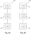
- Figure 6a shows a first exemplary embodiment of the method 100 for producing a tubular body with reduced internal stress by using 3D printing.
- the tubular body has in this case an outer wall with a stiffening structure.
- the stiffening structure extends along at least part of the outer wall.
- a printing plane 38 is set 101 by means of a laser 3D printer 30. This may take place by displacing a printing platform 34 of the 3D printer 30.
- the printing plane 38 may be set 104 by means of a laser 3D printer. In this case, the setting of the printing plane 38 may take place by setting a focal point 36 of the laser beam of a laser 32.
- the printing plane 38 is in this case set such that it is free from parts of the 3D printer 30 and from the tubular body 10 to be produced.
- a tubular body layer 20 is printed 102 in the printing plane 38 by means of the 3D printer.
- the tubular body layer 20 has in this case an outer wall layer 16 and a stiffening structure layer 18, 19.
- the stiffening structure layer 18,19 extends in the printing plane 38 along a periphery 17 of the outer wall layer 16.
- the stiffening structure layer 18, 19 also has at least two portions, which are spaced apart from one another.
- the tubular body layer may be printed 105 from metal according to step b1). Titanium may preferably be used for this. However, other metals are also possible. In this way, a tubular body 10 can be produced from titanium by means of the method 100.
- the tubular body layer may be printed 107 from plastic according to step b2).
- the plastic may be a high-performance plastic, such as for example polyetheretherketone or polyetherimide.
- other types of plastic are also possible.
- steps a) and b) may be repeated 103 until an outer wall 12 with a stiffening structure 14 for a tubular body 10 with reduced internal stress has been produced.
- the repetition 103 of steps a) and b) has the effect that the printing plane 38 is moved successively away from the tubular body layer 20 first produced, so that new tubular body layers 20 can be successively applied to the old tubular body layers 20.
- steps a) and b) may be repeated 106 until a first tubular body layer 21 is at a distance 15 from a last tubular body layer 20 of between 50 mm and 1000 mm.
- the distance may preferably lie between 300 mm and 800 mm, more preferably between 350 mm and 600 mm, and most preferably at 400 mm.
- the method 100 can be used to produce a component which has at least in one dimension a measure of up to 1000 mm, this component having a low internal stress and consequently being of a very stable configuration.
Landscapes
- Engineering & Computer Science (AREA)
- Chemical & Material Sciences (AREA)
- Manufacturing & Machinery (AREA)
- Materials Engineering (AREA)
- Mechanical Engineering (AREA)
- Physics & Mathematics (AREA)
- General Engineering & Computer Science (AREA)
- Optics & Photonics (AREA)
- Plasma & Fusion (AREA)
- Combustion & Propulsion (AREA)
Claims (7)
- Verfahren zum Herstellen eines rohrförmigen Körpers mit verringerter Eigenspannung unter Verwendung von 3D-Laserdruck, wobei der rohrförmige Körper eine Außenwand mit einer Versteifungsstruktur aufweist, wobei sich die Versteifungsstruktur zumindest entlang eines Teils der Außenwand erstreckt, wobei das Verfahren (100) die folgenden Schritte umfasst:a) Einstellen (101) einer Druckebene (38) für 3D-Druck mittels eines 3D-Laserdruckers (30);b) Drucken (102) einer rohrförmigen Körperschicht (20) in der Druckebene (38) mittels des 3D-Laserdruckers, wobei die rohrförmige Körperschicht eine Außenwandschicht (16) und eine Versteifungsstrukturschicht (18, 19) aufweist, wobei sich die Versteifungsstrukturschicht in der Druckebene entlang eines Randes (17) der Außenwandschicht erstreckt, und die Versteifungsstrukturschicht mindestens zwei Abschnitte aufweist, die voneinander beabstandet sind;c) Wiederholen (103) der Schritte a) und b), um eine Außenwand (12) mit einer Versteifungsstruktur (14) für einen rohrförmigen Körper (10) mit verringerter Eigenspannung herzustellen, wobei der rohrförmige Körper (10) ein Verteilerrohr ist, das in zwei Richtungen Oberflächen mit Krümmungen umfasst,wobei eine Zahl von Versteifungsstrukturschichten eine Versteifungsstruktur bildet, die eine rippenartige Netzstruktur bildet, die hexagonal ist und sich über die Außenwand (12) erstreckt,wobei die Außenwandschicht und die Versteifungsstrukturschicht einteilig ausgebildet sind, undwobei die Außenwandschicht und die Versteifungsstruktur eine ununterbrochene, einheitliche nahtlose rohrförmige Körperschicht bilden.
- Verfahren nach Anspruch 1, wobei eine Zahl von Versteifungsstrukturschichten eine Versteifungsstruktur bildet, die sich außerhalb des rohrförmigen Körpers um die Außenwand erstreckt.
- Verfahren nach einem der Ansprüche 1 bis 2, wobei Schritt b) den folgenden Teilschritt umfasst: b1) Drucken (105) der rohrförmigen Körperschicht aus Metall, bevorzugt aus Titan.
- Verfahren nach einem der Ansprüche 1 bis 2, wobei Schritt b) den folgenden Teilschritt umfasst: b2) Drucken (107) der rohrförmigen Körperschicht aus Kunststoff, bevorzugt aus Polyetheretherketonen oder Polyetherimiden.
- Verfahren nach einem der Ansprüche 1 bis 4, wobei Schritt c) den folgenden Teilschritt umfasst: c1) Wiederholen (106) der Schritte a) und b), bis eine erste rohrförmige Körperschicht (21) von einer letzten rohrförmigen Körperschicht (23) zwischen 50 mm und 1000 mm, bevorzugt zwischen 300 mm und 800 mm, besonders bevorzugt zwischen 350 mm und 600 mm, und am meisten bevorzugt 400 mm beabstandet (15) ist.
- Rohrförmiger Körper, der durch ein Verfahren nach einem der Ansprüche 1 bis 5 hergestellt wird, wobei der rohrförmige Körper (10) Folgendes aufweist:- eine Außenwand (12), und- eine Versteifungsstruktur (14), wobei sich die Versteifungsstruktur (14) zumindest entlang eines Teiles der Außenwand (12) erstreckt, die Versteifungsstruktur (14) aus mindestens einer Versteifungsstrukturschicht (18, 19) gebildet ist und die Außenwand (12) durch mindestens eine Außenwandschicht (16) gebildet ist,sich die Versteifungsstrukturschicht (18, 19) entlang eines Randes der Außenwandschicht (16) erstreckt,die Versteifungsstrukturschicht (18, 19) mindestens zwei Abschnitte aufweist, die voneinander beabstandet sind,wobei der rohrförmige Körper (10) ein Verteilerrohr ist, das in zwei Richtungen Oberflächen mit Krümmungen umfasst,wobei eine Zahl von Versteifungsstrukturschichten eine Versteifungsstruktur bildet, die eine rippenartige Netzstruktur bildet, die hexagonal ist und sich über die Außenwand (12) erstreckt,wobei die Außenwandschicht und die Versteifungsstrukturschicht einteilig ausgebildet sind, undwobei die Außenwandschicht und die Versteifungsstruktur eine ununterbrochene, einheitliche nahtlose rohrförmige Körperschicht bilden.
- Flugzeug (40), das Folgendes umfasst:- einen rohrförmigen Körper (10) nach Anspruch 6, und- ein Rohrleitungssystem (42),
wobei der rohrförmige Körper (10) mit dem Rohrleitungssystem (42) fluidkommunikationstechnisch verbunden ist.
Applications Claiming Priority (1)
| Application Number | Priority Date | Filing Date | Title |
|---|---|---|---|
| DE102018104513.1A DE102018104513A1 (de) | 2018-02-28 | 2018-02-28 | Verfahren zum Herstellen eines Rohrkörpers mit reduzierter Eigenspannung unter Verwendung von 3-D-Druck und Rohrkörper mit reduzierter Eigenspannung |
Publications (2)
| Publication Number | Publication Date |
|---|---|
| EP3533540A1 EP3533540A1 (de) | 2019-09-04 |
| EP3533540B1 true EP3533540B1 (de) | 2021-12-08 |
Family
ID=65363094
Family Applications (1)
| Application Number | Title | Priority Date | Filing Date |
|---|---|---|---|
| EP19155874.1A Active EP3533540B1 (de) | 2018-02-28 | 2019-02-07 | Verfahren zur herstellung eines rohrförmigen körpers mit reduzierter interner spannung unter verwendung von laser 3d-druck und rohrförmiger körper mit reduzierter interner spannung |
Country Status (4)
| Country | Link |
|---|---|
| US (1) | US11491701B2 (de) |
| EP (1) | EP3533540B1 (de) |
| CN (1) | CN110202807B (de) |
| DE (1) | DE102018104513A1 (de) |
Families Citing this family (3)
| Publication number | Priority date | Publication date | Assignee | Title |
|---|---|---|---|---|
| US20200094471A1 (en) * | 2018-09-24 | 2020-03-26 | The Boeing Company | Additively-manufactured component having at least one stiffening member and method of forming the same |
| EP3804884B1 (de) * | 2019-10-11 | 2022-03-02 | Heraeus Additive Manufacturing GmbH | Generative fertigung eines dünnwandigen metallgegenstandes mit hoher rundheit und konzentrizität und geringer oberflächenrauheit |
| US12013071B2 (en) | 2021-07-12 | 2024-06-18 | The Boeing Company | Ducts comprising exoskeleton and sound-absorbing structures and vehicles using such ducts |
Citations (1)
| Publication number | Priority date | Publication date | Assignee | Title |
|---|---|---|---|---|
| EP0233339A1 (de) * | 1985-12-23 | 1987-08-26 | GebràDer Sulzer Aktiengesellschaft | Werkstück mit Rippen und Verfahren zu seiner Herstellung |
Family Cites Families (16)
| Publication number | Priority date | Publication date | Assignee | Title |
|---|---|---|---|---|
| GB395239A (en) * | 1932-11-25 | 1933-07-13 | Ioco Rubber & Waterproofing Co | Improvements in or relating to flexible tubing |
| JPS4820417B1 (de) * | 1969-12-27 | 1973-06-21 | ||
| DE3246755A1 (de) * | 1982-12-17 | 1984-06-20 | Richard 4937 Lage Pott | Verfahren zur herstellung eines formkoerpers aus verbundmaterial und nach diesem verfahren hergestellter formkoerper |
| EP2647942B1 (de) * | 2012-04-05 | 2014-10-01 | Institut Für Luft- Und Kältetechnik Gemeinnützige GmbH | Mikrofluidik-Bauteil und Verfahren zu seiner Herstellung |
| EP2898248B1 (de) * | 2012-09-21 | 2016-08-31 | Bombardier Inc. | Zusammengesetzte kraftstoffrohre |
| EP3049704A4 (de) * | 2013-09-23 | 2017-06-14 | United Technologies Corporation | Verfahren zur erzeugung einer stützstruktur von rohrkomponenten zur verleihung von funktionsmerkmalen |
| EP3049703B1 (de) * | 2013-09-27 | 2022-03-30 | Raytheon Technologies Corporation | Brennstoff-/ölverteiler |
| DE102014101907A1 (de) * | 2014-02-14 | 2015-08-20 | Thyssenkrupp Ag | Metallblech mit lokaler metallischer Verstärkung und Verfahren zu dessen Herstellung |
| US20160061381A1 (en) * | 2014-03-17 | 2016-03-03 | Igor K. Kotliar | Pressure Vessels, Design and Method of Manufacturing Using Additive Printing |
| DE102015105603B4 (de) * | 2015-04-13 | 2017-02-09 | Airbus Operations Gmbh | Sandwichpaneel für ein Luftfahrzeug |
| EP3086011B1 (de) * | 2015-04-21 | 2019-07-31 | Airbus Operations GmbH | Doppelwandiges rohr mit integrierter heizfähigkeit für ein luft- oder raumfahrzeug |
| US20180186058A1 (en) * | 2015-06-29 | 2018-07-05 | Covestro Deutschland Ag | Method for producing 3-d objects |
| DE102017201532A1 (de) * | 2016-02-02 | 2017-08-03 | Airbus Defence and Space GmbH | Doppelwandiges Rohrelement und Verfahren zur Herstellung eines doppelwandigen Rohrelements |
| US20180001423A1 (en) * | 2016-07-01 | 2018-01-04 | General Electric Company | Methods and thin walled reinforced structures for additive manufacturing |
| CN107081922B (zh) * | 2017-06-06 | 2019-04-02 | 威海纳川管材有限公司 | 大口径热塑性复合材料长输管及其制造方法和装置 |
| CN107139455A (zh) * | 2017-06-30 | 2017-09-08 | 宁夏共享模具有限公司 | 一种fdm打印应力消除装置及其消应力打印方法 |
-
2018
- 2018-02-28 DE DE102018104513.1A patent/DE102018104513A1/de not_active Ceased
-
2019
- 2019-02-07 EP EP19155874.1A patent/EP3533540B1/de active Active
- 2019-02-13 US US16/275,010 patent/US11491701B2/en active Active
- 2019-02-26 CN CN201910142060.XA patent/CN110202807B/zh active Active
Patent Citations (1)
| Publication number | Priority date | Publication date | Assignee | Title |
|---|---|---|---|---|
| EP0233339A1 (de) * | 1985-12-23 | 1987-08-26 | GebràDer Sulzer Aktiengesellschaft | Werkstück mit Rippen und Verfahren zu seiner Herstellung |
Also Published As
| Publication number | Publication date |
|---|---|
| CN110202807A (zh) | 2019-09-06 |
| US20190263050A1 (en) | 2019-08-29 |
| EP3533540A1 (de) | 2019-09-04 |
| CN110202807B (zh) | 2021-10-29 |
| US11491701B2 (en) | 2022-11-08 |
| DE102018104513A1 (de) | 2019-08-29 |
Similar Documents
| Publication | Publication Date | Title |
|---|---|---|
| EP3533540B1 (de) | Verfahren zur herstellung eines rohrförmigen körpers mit reduzierter interner spannung unter verwendung von laser 3d-druck und rohrförmiger körper mit reduzierter interner spannung | |
| EP3825638A1 (de) | Integrierte hornstrukturen für wärmetauscherköpfe | |
| US10286961B2 (en) | Lightweight vehicle structure flexibly manufactured | |
| US10442002B2 (en) | Manufacturing of components of a vehicle using additive layer manufacturing | |
| CN100467187C (zh) | 船用铝合金t形型材的激光填丝焊接方法 | |
| US8353476B2 (en) | Truss-shaped engine pylon and method of making same | |
| US8939497B2 (en) | Dashboard crossbeam comprising at least two sections attached to each other by welding | |
| EP3269524B1 (de) | Dünnhäutige fahrwerksstrukturen mit verringerung von aerodynamischem lärm und herstellungstechniken | |
| US9623977B2 (en) | Hybrid structure including built-up sandwich structure and monolithic SPF/DB structure | |
| US8302907B2 (en) | Hybrid torque box for a thrust reverser | |
| EP3275780B1 (de) | Dünnwandige strebenträger und fahrwerkanordnungen | |
| US6543721B2 (en) | Stressed-skin component made of metal | |
| US9310023B2 (en) | Methods and systems for distributing inert gas in an aircraft | |
| CN103008998A (zh) | 一种钛合金筒形三层结构的超塑成形/扩散连接成形方法 | |
| WO2008056456A1 (en) | Boiler water wall panel | |
| US9963997B2 (en) | Tank and method for manufacturing same | |
| CN109131566A (zh) | 汽车横梁与纵梁的搭接结构及横、纵梁的焊接方法 | |
| CN110480279B (zh) | 一种钛合金变壁厚空心主动冷却舱体制备方法 | |
| CN108725808A (zh) | 用于飞行器的异形油箱 | |
| JP6577192B2 (ja) | 流体分配システム組立品を製造する方法 | |
| CN119840802B (zh) | 船舶舷侧结构组装方法 | |
| CN114669616A (zh) | 结构部件 | |
| PH12015000310A1 (en) | Butt weld structure and butt welding method for extra thick steel plate | |
| CN105579160A (zh) | 制造连接件的方法以及连接件 | |
| EP4172546B1 (de) | Verfahren zur herstellung eines rippen-platten-wärmetauschers und rippen-platten-wärmetauscher |
Legal Events
| Date | Code | Title | Description |
|---|---|---|---|
| PUAI | Public reference made under article 153(3) epc to a published international application that has entered the european phase |
Free format text: ORIGINAL CODE: 0009012 |
|
| STAA | Information on the status of an ep patent application or granted ep patent |
Free format text: STATUS: THE APPLICATION HAS BEEN PUBLISHED |
|
| AK | Designated contracting states |
Kind code of ref document: A1 Designated state(s): AL AT BE BG CH CY CZ DE DK EE ES FI FR GB GR HR HU IE IS IT LI LT LU LV MC MK MT NL NO PL PT RO RS SE SI SK SM TR |
|
| AX | Request for extension of the european patent |
Extension state: BA ME |
|
| STAA | Information on the status of an ep patent application or granted ep patent |
Free format text: STATUS: REQUEST FOR EXAMINATION WAS MADE |
|
| 17P | Request for examination filed |
Effective date: 20200302 |
|
| RBV | Designated contracting states (corrected) |
Designated state(s): AL AT BE BG CH CY CZ DE DK EE ES FI FR GB GR HR HU IE IS IT LI LT LU LV MC MK MT NL NO PL PT RO RS SE SI SK SM TR |
|
| STAA | Information on the status of an ep patent application or granted ep patent |
Free format text: STATUS: EXAMINATION IS IN PROGRESS |
|
| 17Q | First examination report despatched |
Effective date: 20210121 |
|
| GRAP | Despatch of communication of intention to grant a patent |
Free format text: ORIGINAL CODE: EPIDOSNIGR1 |
|
| STAA | Information on the status of an ep patent application or granted ep patent |
Free format text: STATUS: GRANT OF PATENT IS INTENDED |
|
| INTG | Intention to grant announced |
Effective date: 20210802 |
|
| GRAS | Grant fee paid |
Free format text: ORIGINAL CODE: EPIDOSNIGR3 |
|
| GRAA | (expected) grant |
Free format text: ORIGINAL CODE: 0009210 |
|
| STAA | Information on the status of an ep patent application or granted ep patent |
Free format text: STATUS: THE PATENT HAS BEEN GRANTED |
|
| AK | Designated contracting states |
Kind code of ref document: B1 Designated state(s): AL AT BE BG CH CY CZ DE DK EE ES FI FR GB GR HR HU IE IS IT LI LT LU LV MC MK MT NL NO PL PT RO RS SE SI SK SM TR |
|
| REG | Reference to a national code |
Ref country code: GB Ref legal event code: FG4D |
|
| REG | Reference to a national code |
Ref country code: AT Ref legal event code: REF Ref document number: 1453369 Country of ref document: AT Kind code of ref document: T Effective date: 20211215 Ref country code: CH Ref legal event code: EP |
|
| REG | Reference to a national code |
Ref country code: DE Ref legal event code: R096 Ref document number: 602019009799 Country of ref document: DE |
|
| REG | Reference to a national code |
Ref country code: IE Ref legal event code: FG4D |
|
| REG | Reference to a national code |
Ref country code: LT Ref legal event code: MG9D |
|
| REG | Reference to a national code |
Ref country code: NL Ref legal event code: MP Effective date: 20211208 |
|
| PG25 | Lapsed in a contracting state [announced via postgrant information from national office to epo] |
Ref country code: RS Free format text: LAPSE BECAUSE OF FAILURE TO SUBMIT A TRANSLATION OF THE DESCRIPTION OR TO PAY THE FEE WITHIN THE PRESCRIBED TIME-LIMIT Effective date: 20211208 Ref country code: LT Free format text: LAPSE BECAUSE OF FAILURE TO SUBMIT A TRANSLATION OF THE DESCRIPTION OR TO PAY THE FEE WITHIN THE PRESCRIBED TIME-LIMIT Effective date: 20211208 Ref country code: FI Free format text: LAPSE BECAUSE OF FAILURE TO SUBMIT A TRANSLATION OF THE DESCRIPTION OR TO PAY THE FEE WITHIN THE PRESCRIBED TIME-LIMIT Effective date: 20211208 Ref country code: BG Free format text: LAPSE BECAUSE OF FAILURE TO SUBMIT A TRANSLATION OF THE DESCRIPTION OR TO PAY THE FEE WITHIN THE PRESCRIBED TIME-LIMIT Effective date: 20220308 |
|
| REG | Reference to a national code |
Ref country code: AT Ref legal event code: MK05 Ref document number: 1453369 Country of ref document: AT Kind code of ref document: T Effective date: 20211208 |
|
| PG25 | Lapsed in a contracting state [announced via postgrant information from national office to epo] |
Ref country code: SE Free format text: LAPSE BECAUSE OF FAILURE TO SUBMIT A TRANSLATION OF THE DESCRIPTION OR TO PAY THE FEE WITHIN THE PRESCRIBED TIME-LIMIT Effective date: 20211208 Ref country code: NO Free format text: LAPSE BECAUSE OF FAILURE TO SUBMIT A TRANSLATION OF THE DESCRIPTION OR TO PAY THE FEE WITHIN THE PRESCRIBED TIME-LIMIT Effective date: 20220308 Ref country code: LV Free format text: LAPSE BECAUSE OF FAILURE TO SUBMIT A TRANSLATION OF THE DESCRIPTION OR TO PAY THE FEE WITHIN THE PRESCRIBED TIME-LIMIT Effective date: 20211208 Ref country code: HR Free format text: LAPSE BECAUSE OF FAILURE TO SUBMIT A TRANSLATION OF THE DESCRIPTION OR TO PAY THE FEE WITHIN THE PRESCRIBED TIME-LIMIT Effective date: 20211208 Ref country code: GR Free format text: LAPSE BECAUSE OF FAILURE TO SUBMIT A TRANSLATION OF THE DESCRIPTION OR TO PAY THE FEE WITHIN THE PRESCRIBED TIME-LIMIT Effective date: 20220309 Ref country code: ES Free format text: LAPSE BECAUSE OF FAILURE TO SUBMIT A TRANSLATION OF THE DESCRIPTION OR TO PAY THE FEE WITHIN THE PRESCRIBED TIME-LIMIT Effective date: 20211208 |
|
| PG25 | Lapsed in a contracting state [announced via postgrant information from national office to epo] |
Ref country code: NL Free format text: LAPSE BECAUSE OF FAILURE TO SUBMIT A TRANSLATION OF THE DESCRIPTION OR TO PAY THE FEE WITHIN THE PRESCRIBED TIME-LIMIT Effective date: 20211208 |
|
| PG25 | Lapsed in a contracting state [announced via postgrant information from national office to epo] |
Ref country code: SM Free format text: LAPSE BECAUSE OF FAILURE TO SUBMIT A TRANSLATION OF THE DESCRIPTION OR TO PAY THE FEE WITHIN THE PRESCRIBED TIME-LIMIT Effective date: 20211208 Ref country code: SK Free format text: LAPSE BECAUSE OF FAILURE TO SUBMIT A TRANSLATION OF THE DESCRIPTION OR TO PAY THE FEE WITHIN THE PRESCRIBED TIME-LIMIT Effective date: 20211208 Ref country code: RO Free format text: LAPSE BECAUSE OF FAILURE TO SUBMIT A TRANSLATION OF THE DESCRIPTION OR TO PAY THE FEE WITHIN THE PRESCRIBED TIME-LIMIT Effective date: 20211208 Ref country code: PT Free format text: LAPSE BECAUSE OF FAILURE TO SUBMIT A TRANSLATION OF THE DESCRIPTION OR TO PAY THE FEE WITHIN THE PRESCRIBED TIME-LIMIT Effective date: 20220408 Ref country code: EE Free format text: LAPSE BECAUSE OF FAILURE TO SUBMIT A TRANSLATION OF THE DESCRIPTION OR TO PAY THE FEE WITHIN THE PRESCRIBED TIME-LIMIT Effective date: 20211208 Ref country code: CZ Free format text: LAPSE BECAUSE OF FAILURE TO SUBMIT A TRANSLATION OF THE DESCRIPTION OR TO PAY THE FEE WITHIN THE PRESCRIBED TIME-LIMIT Effective date: 20211208 |
|
| PG25 | Lapsed in a contracting state [announced via postgrant information from national office to epo] |
Ref country code: PL Free format text: LAPSE BECAUSE OF FAILURE TO SUBMIT A TRANSLATION OF THE DESCRIPTION OR TO PAY THE FEE WITHIN THE PRESCRIBED TIME-LIMIT Effective date: 20211208 Ref country code: AT Free format text: LAPSE BECAUSE OF FAILURE TO SUBMIT A TRANSLATION OF THE DESCRIPTION OR TO PAY THE FEE WITHIN THE PRESCRIBED TIME-LIMIT Effective date: 20211208 |
|
| REG | Reference to a national code |
Ref country code: DE Ref legal event code: R097 Ref document number: 602019009799 Country of ref document: DE |
|
| PG25 | Lapsed in a contracting state [announced via postgrant information from national office to epo] |
Ref country code: MC Free format text: LAPSE BECAUSE OF FAILURE TO SUBMIT A TRANSLATION OF THE DESCRIPTION OR TO PAY THE FEE WITHIN THE PRESCRIBED TIME-LIMIT Effective date: 20211208 Ref country code: IS Free format text: LAPSE BECAUSE OF FAILURE TO SUBMIT A TRANSLATION OF THE DESCRIPTION OR TO PAY THE FEE WITHIN THE PRESCRIBED TIME-LIMIT Effective date: 20220408 |
|
| PLBE | No opposition filed within time limit |
Free format text: ORIGINAL CODE: 0009261 |
|
| REG | Reference to a national code |
Ref country code: CH Ref legal event code: PL |
|
| STAA | Information on the status of an ep patent application or granted ep patent |
Free format text: STATUS: NO OPPOSITION FILED WITHIN TIME LIMIT |
|
| REG | Reference to a national code |
Ref country code: BE Ref legal event code: MM Effective date: 20220228 |
|
| PG25 | Lapsed in a contracting state [announced via postgrant information from national office to epo] |
Ref country code: LU Free format text: LAPSE BECAUSE OF NON-PAYMENT OF DUE FEES Effective date: 20220207 Ref country code: DK Free format text: LAPSE BECAUSE OF FAILURE TO SUBMIT A TRANSLATION OF THE DESCRIPTION OR TO PAY THE FEE WITHIN THE PRESCRIBED TIME-LIMIT Effective date: 20211208 Ref country code: AL Free format text: LAPSE BECAUSE OF FAILURE TO SUBMIT A TRANSLATION OF THE DESCRIPTION OR TO PAY THE FEE WITHIN THE PRESCRIBED TIME-LIMIT Effective date: 20211208 |
|
| 26N | No opposition filed |
Effective date: 20220909 |
|
| PG25 | Lapsed in a contracting state [announced via postgrant information from national office to epo] |
Ref country code: SI Free format text: LAPSE BECAUSE OF FAILURE TO SUBMIT A TRANSLATION OF THE DESCRIPTION OR TO PAY THE FEE WITHIN THE PRESCRIBED TIME-LIMIT Effective date: 20211208 |
|
| PG25 | Lapsed in a contracting state [announced via postgrant information from national office to epo] |
Ref country code: LI Free format text: LAPSE BECAUSE OF NON-PAYMENT OF DUE FEES Effective date: 20220228 Ref country code: IE Free format text: LAPSE BECAUSE OF NON-PAYMENT OF DUE FEES Effective date: 20220207 Ref country code: CH Free format text: LAPSE BECAUSE OF NON-PAYMENT OF DUE FEES Effective date: 20220228 |
|
| PG25 | Lapsed in a contracting state [announced via postgrant information from national office to epo] |
Ref country code: BE Free format text: LAPSE BECAUSE OF NON-PAYMENT OF DUE FEES Effective date: 20220228 |
|
| PG25 | Lapsed in a contracting state [announced via postgrant information from national office to epo] |
Ref country code: IT Free format text: LAPSE BECAUSE OF FAILURE TO SUBMIT A TRANSLATION OF THE DESCRIPTION OR TO PAY THE FEE WITHIN THE PRESCRIBED TIME-LIMIT Effective date: 20211208 |
|
| PG25 | Lapsed in a contracting state [announced via postgrant information from national office to epo] |
Ref country code: MK Free format text: LAPSE BECAUSE OF FAILURE TO SUBMIT A TRANSLATION OF THE DESCRIPTION OR TO PAY THE FEE WITHIN THE PRESCRIBED TIME-LIMIT Effective date: 20211208 Ref country code: CY Free format text: LAPSE BECAUSE OF FAILURE TO SUBMIT A TRANSLATION OF THE DESCRIPTION OR TO PAY THE FEE WITHIN THE PRESCRIBED TIME-LIMIT Effective date: 20211208 |
|
| PG25 | Lapsed in a contracting state [announced via postgrant information from national office to epo] |
Ref country code: HU Free format text: LAPSE BECAUSE OF FAILURE TO SUBMIT A TRANSLATION OF THE DESCRIPTION OR TO PAY THE FEE WITHIN THE PRESCRIBED TIME-LIMIT; INVALID AB INITIO Effective date: 20190207 |
|
| PG25 | Lapsed in a contracting state [announced via postgrant information from national office to epo] |
Ref country code: TR Free format text: LAPSE BECAUSE OF FAILURE TO SUBMIT A TRANSLATION OF THE DESCRIPTION OR TO PAY THE FEE WITHIN THE PRESCRIBED TIME-LIMIT Effective date: 20211208 |
|
| PG25 | Lapsed in a contracting state [announced via postgrant information from national office to epo] |
Ref country code: MT Free format text: LAPSE BECAUSE OF FAILURE TO SUBMIT A TRANSLATION OF THE DESCRIPTION OR TO PAY THE FEE WITHIN THE PRESCRIBED TIME-LIMIT Effective date: 20211208 |
|
| PGFP | Annual fee paid to national office [announced via postgrant information from national office to epo] |
Ref country code: GB Payment date: 20260219 Year of fee payment: 8 |
|
| PGFP | Annual fee paid to national office [announced via postgrant information from national office to epo] |
Ref country code: DE Payment date: 20260218 Year of fee payment: 8 |
|
| PGFP | Annual fee paid to national office [announced via postgrant information from national office to epo] |
Ref country code: FR Payment date: 20260218 Year of fee payment: 8 |