EP3533354A1 - Male member of snap fastener and snap fastener - Google Patents
Male member of snap fastener and snap fastener Download PDFInfo
- Publication number
- EP3533354A1 EP3533354A1 EP17866319.1A EP17866319A EP3533354A1 EP 3533354 A1 EP3533354 A1 EP 3533354A1 EP 17866319 A EP17866319 A EP 17866319A EP 3533354 A1 EP3533354 A1 EP 3533354A1
- Authority
- EP
- European Patent Office
- Prior art keywords
- male member
- snap fastener
- fastener according
- protruding portion
- cover
- Prior art date
- Legal status (The legal status is an assumption and is not a legal conclusion. Google has not performed a legal analysis and makes no representation as to the accuracy of the status listed.)
- Granted
Links
Images




Classifications
-
- A—HUMAN NECESSITIES
- A44—HABERDASHERY; JEWELLERY
- A44B—BUTTONS, PINS, BUCKLES, SLIDE FASTENERS, OR THE LIKE
- A44B17/00—Press-button or snap fasteners
- A44B17/0058—Strips of press-button fasteners
-
- A—HUMAN NECESSITIES
- A44—HABERDASHERY; JEWELLERY
- A44B—BUTTONS, PINS, BUCKLES, SLIDE FASTENERS, OR THE LIKE
- A44B17/00—Press-button or snap fasteners
- A44B17/0064—Details
- A44B17/007—Stud-member
-
- A—HUMAN NECESSITIES
- A44—HABERDASHERY; JEWELLERY
- A44B—BUTTONS, PINS, BUCKLES, SLIDE FASTENERS, OR THE LIKE
- A44B13/00—Hook or eye fasteners
- A44B13/0005—Hook or eye fasteners characterised by their material
-
- A—HUMAN NECESSITIES
- A44—HABERDASHERY; JEWELLERY
- A44B—BUTTONS, PINS, BUCKLES, SLIDE FASTENERS, OR THE LIKE
- A44B17/00—Press-button or snap fasteners
-
- A—HUMAN NECESSITIES
- A44—HABERDASHERY; JEWELLERY
- A44B—BUTTONS, PINS, BUCKLES, SLIDE FASTENERS, OR THE LIKE
- A44B17/00—Press-button or snap fasteners
- A44B17/0029—Press-button fasteners made of plastics
-
- A—HUMAN NECESSITIES
- A44—HABERDASHERY; JEWELLERY
- A44B—BUTTONS, PINS, BUCKLES, SLIDE FASTENERS, OR THE LIKE
- A44B17/00—Press-button or snap fasteners
- A44B17/0041—Press-button fasteners consisting of two parts
-
- A—HUMAN NECESSITIES
- A44—HABERDASHERY; JEWELLERY
- A44B—BUTTONS, PINS, BUCKLES, SLIDE FASTENERS, OR THE LIKE
- A44B17/00—Press-button or snap fasteners
- A44B17/0047—Press-button fasteners consisting of three parts
-
- A—HUMAN NECESSITIES
- A44—HABERDASHERY; JEWELLERY
- A44B—BUTTONS, PINS, BUCKLES, SLIDE FASTENERS, OR THE LIKE
- A44B17/00—Press-button or snap fasteners
- A44B17/0052—Press-button fasteners consisting of four parts
-
- A—HUMAN NECESSITIES
- A44—HABERDASHERY; JEWELLERY
- A44B—BUTTONS, PINS, BUCKLES, SLIDE FASTENERS, OR THE LIKE
- A44B17/00—Press-button or snap fasteners
- A44B17/0064—Details
- A44B17/0094—Details made from solid metal
Definitions
- the present invention relates to a male member of a snap fastener.
- male members of snap fasteners are made of a single material, and in most cases are made of plastics or metals. However, male members of snap fasteners must perform various functions, particularly withstand various influences during use and washing. The related male members of snap fasteners do not satisfy many of these requirements.
- Patent Document 1 described below is known as a related male member of a snap fastener.
- Patent Document 1 US2003/0200633
- a first object of the present invention is to improve a male member of a snap fastener so as to satisfy the above many requirements simultaneously, particularly to protect the male member from damages.
- a second object of the present invention is to solve the above-described problems, particularly to protect the engagement protruding portion from damages, and further to improve a visual appearance of the male member.
- the first object of the present invention is achieved by following configuration.
- a male member of a snap fastener is made of at least two materials: a plastic material such as acrylonitrile butadiene styrene (ABS), polyamide (PA), and/or polyoxymethylene (POM), and a metallic material such as aluminum, brass, and/or (stainless) steel.
- ABS acrylonitrile butadiene styrene
- PA polyamide
- POM polyoxymethylene
- metallic material such as aluminum, brass, and/or (stainless) steel.
- a combination of the materials provides more options compared to related male member made of single material so that it is possible to simultaneously meet various requirements.
- the male member includes at least two portions in which a first portion is made of the plastic material and a second portion is made of the metallic material.
- a part of the male member having a complicated shape may be made of a plastic material, and a part of the male member required to have high damage resistance may be made of a metallic material.
- the first portion includes an engagement protruding portion that cooperates with an eyelet of a female member of the snap fastener.
- the engagement protruding portion must meet several requirements and should have a shape that is optimal for snap engagement.
- Manufacture of the first portion based on a plastic material is easier compared to manufacture of the first portion based on a metallic material.
- the first portion can be manufactured by injection molding.
- the engagement protruding portion preferably has flexibility. As a result, it is possible to improve snap engagement procedure and close the snap fastener easily.
- the engagement protruding portion preferably can elastically be deformed so as to expand. Accordingly, the engagement protruding portion is at least partially moved inward to simplify the snap engagement procedure.
- the second portion is preferably disposed between the first portion and holding unit that holds the male member on a support.
- the second portion can protect the first portion from damages resulting from direct abutment of the holding unit against the first portion.
- the second portion is preferably sandwiched between the holding unit and the first portion.
- the holding unit is a rivet. This is a simple and inexpensive method for attaching the male member to the support.
- the second portion has a ring-like washer shape. Since the ring-like washer shape is very simple, it is easy to manufacture.
- the present invention also relates to a snap fastener including the male member and the counterpart female member of the male member, in addition to the male member.
- the ring-like curved wall of the female member that forms the eyelet into which the engagement protruding portion of the male member is inserted has no flexibility. The reason for this is that it is extremely easy and inexpensive to manufacture each of the walls that forms the eyelet.
- the wall is preferably made of a metallic material. Also, the manufacture of the wall based on metal is easy and inexpensive.
- the second object of the present invention is achieved by following configuration.
- the male member of the snap fastener which includes an engagement protruding portion that cooperates with an eyelet of a female member of the snap fastener, is provided with a cover at least partially covering the engagement protruding portion on a side facing the female member when the male member is engaged with the female member.
- the cover is a type of shield that protects the engagement protruding portion from damages, particularly damages from environment and use.
- the cover may be used to improve the visual appearance.
- the engagement protruding portion can be made of any suitable material, but the engagement protruding portion is preferably made of a plastic material such as acrylonitrile butadiene styrene (ABS), polyamide (PA), and/or polyoxymethylene (POM).
- ABS acrylonitrile butadiene styrene
- PA polyamide
- POM polyoxymethylene
- the cover is made of a metal or metal alloy, such as aluminum, brass, and/or (stainless) steel.
- a metal or metal alloy such as aluminum, brass, and/or (stainless) steel.
- the use of metal has several advantages. A metal is less susceptible to be damaged than a plastic material, particularly for mechanical damages such as scratch. Further, it is easy to achieve an attractive appearance of a metal surface.
- a gap exists between an end surface of the engagement protruding portion and the cover.
- the engagement protruding portion can move during snap engagement without being hindered by the cover.
- the movement of the engagement protruding portion during snap engagement is a radial inward movement.
- the cover may be held so as to abut against an end surface of the base.
- the base that may be additionally provided is used to hold the cover in place.
- the cover can at least partially cover the engagement protruding portion on the side facing the female member when the male member is engaged with the female member to protect the engagement protruding portion. Further, the cover may be held with a gap between the end surface of the engagement protruding portion and the cover.
- At least one of the engagement protruding portion and the base is provided in a sleeve shape.
- at least one of the engagement protruding portion and the base is provided in a ring shape as viewed from the side facing the female member when the male member is engaged with the female member.
- Each design is easily achieved by, for example, injection molding.
- the engagement protruding portion is concentrically disposed around the base.
- a space into which the engagement protruding portion moves inward at a time of snap engagement with the female member is provided.
- the space is at least partially covered by the cover.
- a concentric sleeve for example, a ring-shaped space is protected by the cover, so that any foreign matter is prevented from falling into the space and hindering snap engagement.
- the space is not visible at least as long as the space is covered by the cover, so that the visual appearance is improved.
- the space is arranged between the base and the engagement protruding portion.
- the design is easily achieved by, for example, injection molding.
- a holding unit that holds the male member on a support abuts against the cover at the side facing the female member when the male member is engaged with the female member.
- the holding unit has two functions of holding the male member on the support and holding the cover.
- the support may be any material to which the snap fastener is fixed, such as a fibrous material and a leather material.
- the cover may include at least one blocking unit used to prevent movement of the male member in a lateral direction with respect to an engaging direction.
- the cover has two functions. That is, the cover serves to cover or protect the engagement protruding portion, and serves to prevent movement of the male member in the lateral direction with respect to the engaging direction to fix the male member to the support.
- the cover may include an outer flange disposed outward and an inner flange disposed inward.
- the cover may have a sleeve shape or a hollow cylindrical shape such as a pipe shape.
- the outer flange has a function of covering or protecting the engagement protruding portion.
- the inner flange serves as an abutting portion of the holding unit to fix the male member on the support.
- the side wall of the sleeve serves as the blocking unit used to prevent movement of the male member in the lateral direction with respect to the engagement direction.
- the present invention also relates to a snap fastener including the male member.
- a wall that forms the eyelet of the female is made of a metallic material such as aluminum, brass, and/or steel (stainless steel).
- a first embodiment of a male member of a snap fastener according to the present invention and a snap fastener including the male member are described with reference to Figs. 1 to 3 .
- the snap fastener illustrated in Figs. 1 to 3 includes a male member 10 and a female member 12 as a counterpart of the male member 10.
- the male member 10 includes a main body (a first portion) 10A and a cover (a second portion) 11.
- the main body 10A is made of a plastic material such as polyoxymethylene (POM).
- POM polyoxymethylene
- the cover 11 and the female member 12 are made of a metallic material such as brass.
- the snap fastener includes rivets (holding units) 14, 16 used to attach the male member 10 and the female member 12 to fabrics (supports) 18, 20, respectively.
- the main body 10A of the male member 10 includes an engagement protruding portion 22 that cooperates with an eyelet 24 of the female member 12.
- the engagement protruding portion 22 has a sleeve shape and includes a bulging portion 26 on an outer surface in a radial direction.
- the bulging portion 26 cooperates with a wall 28 that forms the eyelet 24 for snap engagement of the male member 10 and the female member 12.
- the engagement projection 22 has flexibility and can elastically expand and deform.
- the cover 11 serves to attach the main body 10A to the fabric 18 since a rivet shaft portion 15 of the rivet 14 abuts against the cover 11 and the cover 11 abuts against the main body 10A of the male member 10. In other words, the cover 11 is sandwiched between the rivet shaft portion 15 and the main body 10A. Thus, since the rivet shaft portion 15 does not directly abut against the main body 10A, it is possible to prevent the main body 10A from damages due to the abutment of the rivet shaft portion 15.
- the cover 11 is made of a metallic material, it is less susceptible to be damaged than a plastic material, particularly for mechanical damages such as scratches that may occur during use and washing. Therefore, the main body 10A of the male member 10 can be protected from being damaged by the cover 11.
- the cover 11 may be supplied as a separate component or may be fixed to the main body 10A of the male member 10 by, for example, bonding and welding.
- the main body 10A of the male member 10 is made of a plastic material, the engagement protruding portion 22 of the main body 10A is easily moved radially inward, particularly during snap engagement. Further, it is easy to provide the bulging portion 26 on the engagement protruding portion 22 by the injection molding process.
- the cover 11 since the cover 11 has a ring-like washer shape, it is easy to manufacture the cover 11.
- the female member 12 since the main body 10A of the male member 10 can have sufficient flexibility to ensure an easy snap engagement procedure, the female member 12 does not need to have flexibility for the snap engagement procedure. Therefore, it is easy to manufacture the female member 12.
- the snap fastener in the present embodiment has an extremely flat structure since attachment of a snap is performed at an edge of the snap rather than a center of the snap. Thus, there is no need to provide, in height of the snap, space for both snap operation and attachment of the male member and the female member to each piece of material made in the same area as the snap operation.
- rivets 14, 16 are attachment units but not parts or members of the snap fastener.
- a second embodiment of a male member of a snap fastener according to the present invention and a snap fastener including the male member are described with reference to Figs. 4 to 6 .
- the snap fastener illustrated in Figs. 4 to 6 includes the male member 10 and the counterpart female member 12 of the male member 10.
- the male member 10 of the present embodiment is made of a plastic material such as polyoxymethylene (POM).
- the female member 12 of the present embodiment is made of a metal such as aluminum, brass, and steel (stainless steel), or a metal alloy.
- the snap fastener includes the rivets (the holding units) 14, 16 used to attach the male member 10 and the female member 12 to the fabrics (the supports) 18, 20, respectively.
- the male member 10 includes an engagement protruding portion 22 that cooperates with the eyelet 24 of the female member 12.
- the engagement protruding portion 22 is provided in a sleeve shape or a hollow cylindrical shape such as a pipe shape, and includes the bulging portion 26 on an outer surface in a radial direction.
- the bulging portion 26 cooperates with the ring-shaped curved wall 28 that forms the eyelet 24 for snap engagement of the male member 10 and the female member 12.
- the male member 10 includes a base 30 formed in a sleeve shape.
- the engagement protruding portion 22 is concentrically disposed around the base 30. Further, as viewed from a side facing the female member 12, a ring-shaped space 32 is arranged between the base 30 and the engagement protruding portion 22. The space 32 is provided so that the engagement protruding portion 22 is movable radially inward at a time of snap engagement with the female member 12.
- the male member 10 is provided with a cover 34 at least partially covering the engagement protruding portion 22 on the side facing the female member 12 when the male member 10 is engaged with the female member 12.
- the cover 34 includes an outer flange 36 disposed radially outward, an inner flange 38 disposed radially inward, and a side wall 40 axially connecting the outer flange 36 and the inner flange 38.
- the cover 34 is formed in a sleeve shape.
- the cover 34 may have a hollow cylindrical shape such as a pipe shape.
- the outer flange 36 of the cover 34 is held so as to abut against one axial end surface (an upper end surface in Fig. 4 ) of the base 30. Further, the outer flange 36 is expanded radially outward beyond the space 32 to at least partially cover the engagement protruding portion 22.
- a gap 42 is provided between the outer flange 36 and one axial end surface (an upper end surface in Fig. 4 ) of the engagement protruding portion 22. Accordingly, the outer flange 36 and the engagement protruding portion 22 are not in direct contact with each other.
- the gap 42 is caused due to the matter that the base 30 is formed higher than the engagement protruding portion 22. Accordingly, the outer flange 36 of the cover 34 does not interfere or prevent movement of the engagement protruding portion 22 during snap engagement.
- the movement of the engagement protruding portion 22 during snap engagement is a radial inward movement.
- the rivet 14 abuts against the inner flange 38 of the cover 34 on the side facing the female member 12.
- the inner flange 38 abuts against a radially inner part of the male member 10.
- the inner flange 38 serves to attach the male member 10 to the fabric 18. Since the inner flange 38 is disposed between the rivet 14 and the male member 10 so that the rivet 14 does not directly abut against the male member 10, it is possible to prevent the radially inner part of the male member 10 from damages due to the abutment of the rivet 14.
- the side wall 40 of the cover 34 is provided in a sleeve shape. Radially outer circumferential surface of the side wall 40 abuts against the base 30 of the male member 10.
- the side wall 40 functions as a blocking unit used to prevent movement of the male member in a lateral direction with respect to an engaging direction by abutting against the base 30, and serves to fix the male member 10 to the fabric 18.
- the cover 34 of the present embodiment is made of a metal such as aluminum, brass, and steel (stainless steel) or a metal alloy. Therefore, it is less susceptible to be damaged than a plastic material, particularly for mechanical damages such as scratches that may occur during use and washing. Therefore, the male member 10 including the base 30, and particularly the engagement protruding portion 22, can be protected from being damaged by the cover 34.
- the cover 34 covers an upper part of the space 32 of the male member 10 to protect the space 32. As a result, it is possible to prevent any foreign matter from falling into the space 32, thereby preventing snap engagement of the engagement protruding portion 22 from being hindered.
- the metallic cover 34 contributes to achieving an attractive appearance of the snap fastener. Since it is easy to apply each decorative element to a metal surface, design, logo, and other aesthetic feature can be easily assembled on the cover 34. Further, since the space 32 is covered by the cover 34 and cannot be seen, visual appearances of the male member 10 and the snap fastener can be improved.
- the cover 34 may be supplied as a separate component or may be fixed to the male member 10 by, for example, bonding and welding.
- the snap fastener illustrated in the figures has a circular profile in a top view and a bottom view.
- the snap fastener in the present embodiment has an extremely flat structure since attachment of a snap is performed at an edge of the snap rather than a center of the snap. Thus, there is no need to provide, in height of the snap, space for both snap operation and attachment of the male member and the female member to each piece of material made in the same area as the snap operation.
- rivets 14, 16 are attachment units and not parts or members of the snap fastener.
Landscapes
- Slide Fasteners, Snap Fasteners, And Hook Fasteners (AREA)
Abstract
Description
- The present invention relates to a male member of a snap fastener.
- Related male members of snap fasteners are made of a single material, and in most cases are made of plastics or metals. However, male members of snap fasteners must perform various functions, particularly withstand various influences during use and washing. The related male members of snap fasteners do not satisfy many of these requirements.
- Patent Document 1 described below is known as a related male member of a snap fastener.
- In the male member described in Patent Document 1 described below, since a engagement protruding portion extends in a direction of a main shaft of the snap fastener, an end surface of the engagement protruding portion may be damaged when the snap fastener is not engaged. Since a surface of the engagement protruding portion is likely to be damaged, the engagement protruding portion of the male member in the related art is scratched or deformed after a certain period of use. Further, design possibilities of the engagement protruding portion of the male member in the related art are limited due to functional requirements. Therefore, it is difficult to achieve an attractive appearance of the male member.
- Patent Document 1:
US2003/0200633 - Therefore, a first object of the present invention is to improve a male member of a snap fastener so as to satisfy the above many requirements simultaneously, particularly to protect the male member from damages. A second object of the present invention is to solve the above-described problems, particularly to protect the engagement protruding portion from damages, and further to improve a visual appearance of the male member.
- The first object of the present invention is achieved by following configuration.
- A male member of a snap fastener is made of at least two materials: a plastic material such as acrylonitrile butadiene styrene (ABS), polyamide (PA), and/or polyoxymethylene (POM), and a metallic material such as aluminum, brass, and/or (stainless) steel.
- A combination of the materials provides more options compared to related male member made of single material so that it is possible to simultaneously meet various requirements.
- Preferably, the male member includes at least two portions in which a first portion is made of the plastic material and a second portion is made of the metallic material. For example, a part of the male member having a complicated shape may be made of a plastic material, and a part of the male member required to have high damage resistance may be made of a metallic material.
- According to a further preferred embodiment of the present invention, the first portion includes an engagement protruding portion that cooperates with an eyelet of a female member of the snap fastener. The engagement protruding portion must meet several requirements and should have a shape that is optimal for snap engagement. Manufacture of the first portion based on a plastic material is easier compared to manufacture of the first portion based on a metallic material. Specifically, the first portion can be manufactured by injection molding.
- The engagement protruding portion preferably has flexibility. As a result, it is possible to improve snap engagement procedure and close the snap fastener easily.
- Specifically, the engagement protruding portion preferably can elastically be deformed so as to expand. Accordingly, the engagement protruding portion is at least partially moved inward to simplify the snap engagement procedure.
- The second portion is preferably disposed between the first portion and holding unit that holds the male member on a support. Thus, the second portion can protect the first portion from damages resulting from direct abutment of the holding unit against the first portion.
- In order to enhance stability, the second portion is preferably sandwiched between the holding unit and the first portion.
- The holding unit is a rivet. This is a simple and inexpensive method for attaching the male member to the support.
- According to a further preferred embodiment of the present invention, the second portion has a ring-like washer shape. Since the ring-like washer shape is very simple, it is easy to manufacture.
- The present invention also relates to a snap fastener including the male member and the counterpart female member of the male member, in addition to the male member. The ring-like curved wall of the female member that forms the eyelet into which the engagement protruding portion of the male member is inserted has no flexibility. The reason for this is that it is extremely easy and inexpensive to manufacture each of the walls that forms the eyelet.
- Finally, the wall is preferably made of a metallic material. Also, the manufacture of the wall based on metal is easy and inexpensive.
- The second object of the present invention is achieved by following configuration.
- The male member of the snap fastener, which includes an engagement protruding portion that cooperates with an eyelet of a female member of the snap fastener, is provided with a cover at least partially covering the engagement protruding portion on a side facing the female member when the male member is engaged with the female member.
- In other words, the cover is a type of shield that protects the engagement protruding portion from damages, particularly damages from environment and use. In addition, the cover may be used to improve the visual appearance.
- The engagement protruding portion can be made of any suitable material, but the engagement protruding portion is preferably made of a plastic material such as acrylonitrile butadiene styrene (ABS), polyamide (PA), and/or polyoxymethylene (POM).
- According to the preferred embodiment, the cover is made of a metal or metal alloy, such as aluminum, brass, and/or (stainless) steel. The use of metal has several advantages. A metal is less susceptible to be damaged than a plastic material, particularly for mechanical damages such as scratch. Further, it is easy to achieve an attractive appearance of a metal surface.
- According to the further preferred embodiment of the present invention, a gap exists between an end surface of the engagement protruding portion and the cover. As a result, the engagement protruding portion can move during snap engagement without being hindered by the cover. Specifically, the movement of the engagement protruding portion during snap engagement is a radial inward movement.
- The cover may be held so as to abut against an end surface of the base. In other words, the base that may be additionally provided is used to hold the cover in place. Thus, the cover can at least partially cover the engagement protruding portion on the side facing the female member when the male member is engaged with the female member to protect the engagement protruding portion. Further, the cover may be held with a gap between the end surface of the engagement protruding portion and the cover.
- According to the further preferred embodiment of the present invention, at least one of the engagement protruding portion and the base is provided in a sleeve shape. In other words, at least one of the engagement protruding portion and the base is provided in a ring shape as viewed from the side facing the female member when the male member is engaged with the female member. Each design is easily achieved by, for example, injection molding.
- Preferably, the engagement protruding portion is concentrically disposed around the base. In other words, for example, there are two sleeves disposed concentrically with each other.
- According to the further preferred embodiment of the present invention, a space into which the engagement protruding portion moves inward at a time of snap engagement with the female member is provided. The space is at least partially covered by the cover. As a result, in case of a concentric sleeve, for example, a ring-shaped space is protected by the cover, so that any foreign matter is prevented from falling into the space and hindering snap engagement. In addition, the space is not visible at least as long as the space is covered by the cover, so that the visual appearance is improved.
- According to the present invention, as viewed from the side facing the female member when the male member is engaged with the female member, the space is arranged between the base and the engagement protruding portion. The design is easily achieved by, for example, injection molding.
- According to the further preferred embodiment of the present invention, a holding unit that holds the male member on a support abuts against the cover at the side facing the female member when the male member is engaged with the female member. Thus, the holding unit has two functions of holding the male member on the support and holding the cover. The support may be any material to which the snap fastener is fixed, such as a fibrous material and a leather material.
- The cover may include at least one blocking unit used to prevent movement of the male member in a lateral direction with respect to an engaging direction. Thus, the cover has two functions. That is, the cover serves to cover or protect the engagement protruding portion, and serves to prevent movement of the male member in the lateral direction with respect to the engaging direction to fix the male member to the support.
- The cover may include an outer flange disposed outward and an inner flange disposed inward. The cover may have a sleeve shape or a hollow cylindrical shape such as a pipe shape. Thus, the outer flange has a function of covering or protecting the engagement protruding portion. The inner flange serves as an abutting portion of the holding unit to fix the male member on the support. The side wall of the sleeve serves as the blocking unit used to prevent movement of the male member in the lateral direction with respect to the engagement direction.
- The present invention also relates to a snap fastener including the male member.
- Preferably, a wall that forms the eyelet of the female is made of a metallic material such as aluminum, brass, and/or steel (stainless steel).
- Hereinafter, the present invention is described in further detail using preferred exemplary embodiments with reference to the accompanying drawings.
-
-
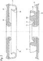
Fig. 1 is an exploded cross-sectional view of a snap fastener including a male member according to a first embodiment of the present invention. -
Fig. 2 is a cross-sectional view illustrating an open state of the snap fastener inFig. 1 attached to a fabric. -
Fig. 3 is a cross-sectional view of the snap fastener inFig. 2 in a closed state. -
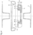
Fig. 4 is an exploded cross-sectional view of a snap fastener including a male member according to a second embodiment of the present invention. -
Fig. 5 is a cross-sectional view illustrating an open state of the snap fastener inFig. 4 attached to a fabric. -
Fig. 6 is a cross-sectional view of the snap fastener inFig. 5 in a closed state. - First, a first embodiment of a male member of a snap fastener according to the present invention and a snap fastener including the male member are described with reference to
Figs. 1 to 3 . - The snap fastener illustrated in
Figs. 1 to 3 includes amale member 10 and afemale member 12 as a counterpart of themale member 10. Themale member 10 includes a main body (a first portion) 10A and a cover (a second portion) 11. Themain body 10A is made of a plastic material such as polyoxymethylene (POM). Thecover 11 and thefemale member 12 are made of a metallic material such as brass. The snap fastener includes rivets (holding units) 14, 16 used to attach themale member 10 and thefemale member 12 to fabrics (supports) 18, 20, respectively. - The
main body 10A of themale member 10 includes anengagement protruding portion 22 that cooperates with aneyelet 24 of thefemale member 12. Theengagement protruding portion 22 has a sleeve shape and includes a bulgingportion 26 on an outer surface in a radial direction. The bulgingportion 26 cooperates with awall 28 that forms theeyelet 24 for snap engagement of themale member 10 and thefemale member 12. Further, theengagement projection 22 has flexibility and can elastically expand and deform. - The
cover 11 serves to attach themain body 10A to thefabric 18 since arivet shaft portion 15 of therivet 14 abuts against thecover 11 and thecover 11 abuts against themain body 10A of themale member 10. In other words, thecover 11 is sandwiched between therivet shaft portion 15 and themain body 10A. Thus, since therivet shaft portion 15 does not directly abut against themain body 10A, it is possible to prevent themain body 10A from damages due to the abutment of therivet shaft portion 15. - Since the
cover 11 is made of a metallic material, it is less susceptible to be damaged than a plastic material, particularly for mechanical damages such as scratches that may occur during use and washing. Therefore, themain body 10A of themale member 10 can be protected from being damaged by thecover 11. - The
cover 11 may be supplied as a separate component or may be fixed to themain body 10A of themale member 10 by, for example, bonding and welding. - Since the
main body 10A of themale member 10 is made of a plastic material, theengagement protruding portion 22 of themain body 10A is easily moved radially inward, particularly during snap engagement. Further, it is easy to provide the bulgingportion 26 on theengagement protruding portion 22 by the injection molding process. - Further, in the present embodiment, since the
cover 11 has a ring-like washer shape, it is easy to manufacture thecover 11. - Further, since the
main body 10A of themale member 10 can have sufficient flexibility to ensure an easy snap engagement procedure, thefemale member 12 does not need to have flexibility for the snap engagement procedure. Therefore, it is easy to manufacture thefemale member 12. - As illustrated in
Figs. 2 and3 , the snap fastener in the present embodiment has an extremely flat structure since attachment of a snap is performed at an edge of the snap rather than a center of the snap. Thus, there is no need to provide, in height of the snap, space for both snap operation and attachment of the male member and the female member to each piece of material made in the same area as the snap operation. - Finally, it should be noted that the
rivets - Features of the present invention disclosed in the above specification, claims, and drawings may be essential to realization of the present invention in various individual embodiments and any combination of these embodiments.
- First, a second embodiment of a male member of a snap fastener according to the present invention and a snap fastener including the male member are described with reference to
Figs. 4 to 6 . - The snap fastener illustrated in
Figs. 4 to 6 includes themale member 10 and the counterpartfemale member 12 of themale member 10. Themale member 10 of the present embodiment is made of a plastic material such as polyoxymethylene (POM). Thefemale member 12 of the present embodiment is made of a metal such as aluminum, brass, and steel (stainless steel), or a metal alloy. The snap fastener includes the rivets (the holding units) 14, 16 used to attach themale member 10 and thefemale member 12 to the fabrics (the supports) 18, 20, respectively. - The
male member 10 includes anengagement protruding portion 22 that cooperates with theeyelet 24 of thefemale member 12. Theengagement protruding portion 22 is provided in a sleeve shape or a hollow cylindrical shape such as a pipe shape, and includes the bulgingportion 26 on an outer surface in a radial direction. The bulgingportion 26 cooperates with the ring-shapedcurved wall 28 that forms theeyelet 24 for snap engagement of themale member 10 and thefemale member 12. - The
male member 10 includes a base 30 formed in a sleeve shape. Theengagement protruding portion 22 is concentrically disposed around thebase 30. Further, as viewed from a side facing thefemale member 12, a ring-shapedspace 32 is arranged between the base 30 and theengagement protruding portion 22. Thespace 32 is provided so that theengagement protruding portion 22 is movable radially inward at a time of snap engagement with thefemale member 12. - The
male member 10 is provided with acover 34 at least partially covering theengagement protruding portion 22 on the side facing thefemale member 12 when themale member 10 is engaged with thefemale member 12. Thecover 34 includes anouter flange 36 disposed radially outward, aninner flange 38 disposed radially inward, and aside wall 40 axially connecting theouter flange 36 and theinner flange 38. Thecover 34 is formed in a sleeve shape. Thecover 34 may have a hollow cylindrical shape such as a pipe shape. - The
outer flange 36 of thecover 34 is held so as to abut against one axial end surface (an upper end surface inFig. 4 ) of thebase 30. Further, theouter flange 36 is expanded radially outward beyond thespace 32 to at least partially cover theengagement protruding portion 22. Agap 42 is provided between theouter flange 36 and one axial end surface (an upper end surface inFig. 4 ) of theengagement protruding portion 22. Accordingly, theouter flange 36 and theengagement protruding portion 22 are not in direct contact with each other. Thegap 42 is caused due to the matter that thebase 30 is formed higher than theengagement protruding portion 22. Accordingly, theouter flange 36 of thecover 34 does not interfere or prevent movement of theengagement protruding portion 22 during snap engagement. The movement of theengagement protruding portion 22 during snap engagement is a radial inward movement. - The
rivet 14 abuts against theinner flange 38 of thecover 34 on the side facing thefemale member 12. Theinner flange 38 abuts against a radially inner part of themale member 10. Thus, theinner flange 38 serves to attach themale member 10 to thefabric 18. Since theinner flange 38 is disposed between therivet 14 and themale member 10 so that therivet 14 does not directly abut against themale member 10, it is possible to prevent the radially inner part of themale member 10 from damages due to the abutment of therivet 14. - The
side wall 40 of thecover 34 is provided in a sleeve shape. Radially outer circumferential surface of theside wall 40 abuts against thebase 30 of themale member 10. Theside wall 40 functions as a blocking unit used to prevent movement of the male member in a lateral direction with respect to an engaging direction by abutting against thebase 30, and serves to fix themale member 10 to thefabric 18. - The
cover 34 of the present embodiment is made of a metal such as aluminum, brass, and steel (stainless steel) or a metal alloy. Therefore, it is less susceptible to be damaged than a plastic material, particularly for mechanical damages such as scratches that may occur during use and washing. Therefore, themale member 10 including thebase 30, and particularly theengagement protruding portion 22, can be protected from being damaged by thecover 34. - Further, the
cover 34 covers an upper part of thespace 32 of themale member 10 to protect thespace 32. As a result, it is possible to prevent any foreign matter from falling into thespace 32, thereby preventing snap engagement of theengagement protruding portion 22 from being hindered. - In addition, the
metallic cover 34 contributes to achieving an attractive appearance of the snap fastener. Since it is easy to apply each decorative element to a metal surface, design, logo, and other aesthetic feature can be easily assembled on thecover 34. Further, since thespace 32 is covered by thecover 34 and cannot be seen, visual appearances of themale member 10 and the snap fastener can be improved. - The
cover 34 may be supplied as a separate component or may be fixed to themale member 10 by, for example, bonding and welding. - The snap fastener illustrated in the figures has a circular profile in a top view and a bottom view.
- As illustrated in
Figs. 5 and6 , the snap fastener in the present embodiment has an extremely flat structure since attachment of a snap is performed at an edge of the snap rather than a center of the snap. Thus, there is no need to provide, in height of the snap, space for both snap operation and attachment of the male member and the female member to each piece of material made in the same area as the snap operation. - Finally, it should be noted that the
rivets - Features of the present invention disclosed in the above specification, claims, and drawings may be integral to realizations of the present invention in various embodiments individually as well as in any combination.
- The present application is based on German Federal Communications Patent Application (
102016012899.2) filed on October 28, 2016 , and German Federal Communications Patent Application (102016012901.8) filed on October 28, 2016 , contents of which are incorporated herein by reference. -
- 10
- male member
- 10
- main body (first portion)
- 11
- cover (second portion)
- 12
- female member
- 14, 16
- rivet (holding unit)
- 15
- rivet shaft portion
- 18, 20
- fabric (support)
- 22
- engagement protruding portion
- 24
- eyelet
- 26
- bulging portion
- 28
- wall
-
- 10
- male member
- 12
- female member
- 14, 16
- rivet (holding unit)
- 18, 20
- fabric (support)
- 22
- engagement protruding portion
- 24
- eyelet
- 26
- bulging portion
- 28
- curved wall
- 30
- base
- 32
- space
- 34
- cover
- 36
- outer flange
- 38
- inner flange
- 40
- side wall (blocking unit)
- 42
- gap
Claims (25)
- A male member (10) of a snap fastener,
wherein the male member (10) of the snap fastener is made of at least a plastic material and a metallic material. - The male member (10) of the snap fastener according to claim 1,
wherein the male member (10) is made of at least two portions in which a first portion (10A) is made of a plastic material and a second portion (11) is made of a metallic portion. - The male member (10) of the snap fastener according to claim 2,
wherein the first portion (10A) includes an engagement protruding portion (22) that cooperates with an eyelet (24) of a female member (12) of the snap fastener. - The male member (10) of the snap fastener according to claim 3,
wherein the engagement protruding portion (22) has flexibility. - The male member (10) of the snap fastener according to claim 3 or 4,
wherein the engagement protruding portion (22) is configured to be deformed so as to expand. - The male member (10) of the snap fastener according to any one of claims 2 to 5,
wherein the second portion (11) is disposed between the first portion (10A) and a holding unit (14, 15) that holds the male member (10) on a support (18). - The male member (10) of the snap fastener according to claim 6,
wherein the second portion (11) is sandwiched between the holding unit (14, 15) and the first portion (10A). - The male member (10) of the snap fastener according to claim 6 or 7,
wherein the holding unit (14) is a rivet. - The male member (10) of the snap fastener according to any one of claims 2 to 8,
wherein the second portion (11) has a ring-like washer shape. - A snap fastener including the male member (10) according to any one of claims 1 to 9 and the female member (12) as a counterpart of the male member (10),
wherein a wall (28) of the female member (12) that forms an eyelet (24) into which the engagement protruding portion (22) of the male member (10) is inserted has no flexibility. - The snap fastener according to claim 10,
wherein the wall (28) is made of a metallic material. - The male member (10) of the snap fastener according to claim 1, including an engagement protruding portion (22) that cooperates with an eyelet (24) of a female member (12) of the snap fastener, the male member (10) comprising:
a cover (34) that at least partially covers the engagement protruding portion (22) on a side facing the female member (12) when the male member (10) is engaged with the female member (12). - The male member (10) of the snap fastener according to claim 12,
wherein the engagement protruding portion (22) is made of a plastic material. - The male member (10) of the snap fastener according to claim 12 or 13,
wherein the cover (34) is made of a metal or a metal alloy. - The male member (10) of the snap fastener according to any one of claims 12 to 14,
wherein a gap (42) exists between an end surface of the engagement protruding portion (22) and the cover (34). - The male member (10) of the snap fastener according to claim 15,
wherein the cover (34) is held so as to abut against an end surface of a base (30). - The male member (10) of the snap fastener according to claim 16,
wherein at least one of the engagement protruding portion (22) and the base (30) has a sleeve shape. - The male member (10) of the snap fastener according to claim 16,
wherein the engagement protruding portion (22) is concentrically disposed around the base (30). - The male member (10) of the snap fastener according to any one of claims 16 to 18,
wherein a space (32) into which the engagement protruding portion (22) moves inward at a time of snap engagement with the female member (12) is provided. - The male member (10) of the snap fastener according to claim 19,
wherein as viewed from a side facing the female member (12) when the male member (10) is engaged with the female member (12), the space (32) is disposed between the base (30) and the engagement protruding portion (22). - The male member (10) of the snap fastener according to any one of claims 12 to 20,
wherein a holding unit (14) that holds the male member (10) on a support (18) abuts against the cover (34) on the side facing the female member (12) when the male member (10) is engaged with the female member (12). - The male member (10) of the snap fastener according to any one of claims 12 to 21,
wherein the cover (34) includes at least one blocking unit (40) that prevents movement of the male member (10) in a lateral direction with respect to an engagement direction. - The male member (10) of the snap fastener according to any one of claims 12 to 22,
wherein the cover (34) has a sleeve shape which includes an outer flange (36) disposed outward and an inner flange (38) disposed inward. - A snap fastener including the male member (10) according to any one of claims 12 to 23.
- The snap fastener according to claim 24,
wherein a wall (28) that forms the eyelet (24) is made of a metallic material.
Applications Claiming Priority (3)
| Application Number | Priority Date | Filing Date | Title |
|---|---|---|---|
| DE102016012899.2A DE102016012899A1 (en) | 2016-10-28 | 2016-10-28 | Patrizenteil a push button and push button with such a male part |
| DE102016012901.8A DE102016012901A1 (en) | 2016-10-28 | 2016-10-28 | Patrizenteil a push button and push button with such a male part |
| PCT/JP2017/038703 WO2018079654A1 (en) | 2016-10-28 | 2017-10-26 | Male member of snap fastener and snap fastener |
Publications (3)
| Publication Number | Publication Date |
|---|---|
| EP3533354A1 true EP3533354A1 (en) | 2019-09-04 |
| EP3533354A4 EP3533354A4 (en) | 2020-07-08 |
| EP3533354B1 EP3533354B1 (en) | 2022-02-23 |
Family
ID=62023638
Family Applications (1)
| Application Number | Title | Priority Date | Filing Date |
|---|---|---|---|
| EP17866319.1A Active EP3533354B1 (en) | 2016-10-28 | 2017-10-26 | Male member of snap fastener and snap fastener |
Country Status (7)
| Country | Link |
|---|---|
| US (2) | US11064772B2 (en) |
| EP (1) | EP3533354B1 (en) |
| JP (1) | JP6719580B2 (en) |
| KR (1) | KR102183351B1 (en) |
| CN (1) | CN109890239B (en) |
| ES (1) | ES2910851T3 (en) |
| WO (1) | WO2018079654A1 (en) |
Families Citing this family (3)
| Publication number | Priority date | Publication date | Assignee | Title |
|---|---|---|---|---|
| CN109890239B (en) | 2016-10-28 | 2021-11-16 | Ykk株式会社 | Convex part of snap fastener and snap fastener |
| JP6847725B2 (en) * | 2017-03-23 | 2021-03-24 | Ykk株式会社 | Female button and combination of female button and male button |
| US20250031809A1 (en) * | 2023-07-27 | 2025-01-30 | Laura Lynne Baltes | Snap on accessory for garments |
Family Cites Families (21)
| Publication number | Priority date | Publication date | Assignee | Title |
|---|---|---|---|---|
| GB559336A (en) | 1942-08-11 | 1944-02-15 | Charles Augustus Belton | An improvement in or relating to land-levelling or earth-moving appliances |
| US2440684A (en) * | 1944-09-28 | 1948-05-04 | Scovill Manufacturing Co | Socket for snap fasteners |
| GB659336A (en) * | 1948-04-19 | 1951-10-24 | United Carr Fastener Corp | Improvements in and relating to securing articles to plastic material |
| US2986790A (en) * | 1959-08-03 | 1961-06-06 | Rau Fastener Company | Snap fastener construction |
| US3551963A (en) * | 1968-08-16 | 1971-01-05 | Walter W Mosher Jr | Self-locking snap fastener |
| US4577376A (en) * | 1982-01-01 | 1986-03-25 | Clendinen Charles D | Snap fastener |
| JPS59166714U (en) * | 1983-04-22 | 1984-11-08 | 古川 宮子 | Synthetic resin hook |
| JPS59166714A (en) | 1984-02-29 | 1984-09-20 | Hitachi Constr Mach Co Ltd | Bearing |
| JP3084341B2 (en) | 1994-07-18 | 2000-09-04 | スコービル・ジャパン株式会社 | Structure of snap button |
| JP3143347B2 (en) * | 1994-12-30 | 2001-03-07 | ワイケイケイ株式会社 | Snap button |
| JPH0994107A (en) * | 1995-10-02 | 1997-04-08 | Osaka Bijiyou Kogyo Kk | Snap button |
| JP3996453B2 (en) | 2002-04-30 | 2007-10-24 | モリト株式会社 | Fasteners with tapes, their production and use |
| JP4221344B2 (en) * | 2004-09-03 | 2009-02-12 | Ykk株式会社 | Stop and button |
| AT502862B1 (en) * | 2005-05-23 | 2009-01-15 | Stumpfl Reinhold Ing | CONNECTION DEVICE |
| JP4989520B2 (en) * | 2008-02-29 | 2012-08-01 | Ykk株式会社 | Male snap and female snap |
| KR20100007632A (en) * | 2008-07-14 | 2010-01-22 | 민경석 | Metal button to coating for skin protection |
| US8561269B2 (en) | 2010-09-17 | 2013-10-22 | Ykk Corporation | Fastener having a flexible base |
| DE202013001808U1 (en) * | 2013-02-25 | 2013-03-05 | Ykk Stocko Fasteners Gmbh | Die component and male component of a push button, and push button composed therefrom |
| DE102016012899A1 (en) | 2016-10-28 | 2018-05-03 | Ykk Corp. | Patrizenteil a push button and push button with such a male part |
| CN109890239B (en) | 2016-10-28 | 2021-11-16 | Ykk株式会社 | Convex part of snap fastener and snap fastener |
| DE102016012901A1 (en) | 2016-10-28 | 2018-05-03 | Ykk Corp. | Patrizenteil a push button and push button with such a male part |
-
2017
- 2017-10-26 CN CN201780066596.7A patent/CN109890239B/en active Active
- 2017-10-26 ES ES17866319T patent/ES2910851T3/en active Active
- 2017-10-26 US US16/345,090 patent/US11064772B2/en active Active
- 2017-10-26 WO PCT/JP2017/038703 patent/WO2018079654A1/en not_active Ceased
- 2017-10-26 KR KR1020197011982A patent/KR102183351B1/en active Active
- 2017-10-26 EP EP17866319.1A patent/EP3533354B1/en active Active
- 2017-10-26 JP JP2018547753A patent/JP6719580B2/en active Active
-
2021
- 2021-06-23 US US17/355,344 patent/US11717061B2/en active Active
Also Published As
| Publication number | Publication date |
|---|---|
| WO2018079654A1 (en) | 2018-05-03 |
| JP6719580B2 (en) | 2020-07-08 |
| EP3533354B1 (en) | 2022-02-23 |
| EP3533354A4 (en) | 2020-07-08 |
| KR20190053944A (en) | 2019-05-20 |
| CN109890239B (en) | 2021-11-16 |
| ES2910851T3 (en) | 2022-05-13 |
| CN109890239A (en) | 2019-06-14 |
| US11717061B2 (en) | 2023-08-08 |
| US20190281931A1 (en) | 2019-09-19 |
| US11064772B2 (en) | 2021-07-20 |
| KR102183351B1 (en) | 2020-11-27 |
| JPWO2018079654A1 (en) | 2019-06-24 |
| US20210315326A1 (en) | 2021-10-14 |
Similar Documents
| Publication | Publication Date | Title |
|---|---|---|
| US11717061B2 (en) | Male member of snap fastener and snap fastener | |
| EP2441340B1 (en) | Improvements in a press-stud | |
| US10278457B2 (en) | Female snap button | |
| US10194718B2 (en) | Snap fastener with a differentiated buttoning and unbuttoning effort female part | |
| EP2709481A1 (en) | Press-stud or snap fastener, particularly for items of clothing and the like | |
| US2134037A (en) | Fastener | |
| US8413853B2 (en) | Attachment device and dispenser using such a device | |
| US3414949A (en) | Snap fastener with removable ornamental button | |
| US5375302A (en) | Snap button assembly | |
| US8042238B2 (en) | Snap fastener part | |
| US2129825A (en) | Laundryproof resilient socket | |
| RU2400115C9 (en) | Female part of button fastener | |
| US10925352B2 (en) | Button assembly with removable cap | |
| US20080282516A1 (en) | Apparatus of Fixing a Belt Buckle | |
| US11700919B2 (en) | Button attachment tool | |
| EP2893828B1 (en) | Removable covering cap for substantially cylindrical buttons | |
| CN113163905B (en) | Push button and female push button | |
| US2510990A (en) | Wheel cover | |
| JP2021154120A (en) | Male type snap button | |
| JPH08182510A (en) | Snap button |
Legal Events
| Date | Code | Title | Description |
|---|---|---|---|
| STAA | Information on the status of an ep patent application or granted ep patent |
Free format text: STATUS: THE INTERNATIONAL PUBLICATION HAS BEEN MADE |
|
| PUAI | Public reference made under article 153(3) epc to a published international application that has entered the european phase |
Free format text: ORIGINAL CODE: 0009012 |
|
| STAA | Information on the status of an ep patent application or granted ep patent |
Free format text: STATUS: REQUEST FOR EXAMINATION WAS MADE |
|
| 17P | Request for examination filed |
Effective date: 20190424 |
|
| AK | Designated contracting states |
Kind code of ref document: A1 Designated state(s): AL AT BE BG CH CY CZ DE DK EE ES FI FR GB GR HR HU IE IS IT LI LT LU LV MC MK MT NL NO PL PT RO RS SE SI SK SM TR |
|
| AX | Request for extension of the european patent |
Extension state: BA ME |
|
| DAV | Request for validation of the european patent (deleted) | ||
| DAX | Request for extension of the european patent (deleted) | ||
| A4 | Supplementary search report drawn up and despatched |
Effective date: 20200605 |
|
| RIC1 | Information provided on ipc code assigned before grant |
Ipc: A44B 17/00 20060101AFI20200529BHEP |
|
| STAA | Information on the status of an ep patent application or granted ep patent |
Free format text: STATUS: EXAMINATION IS IN PROGRESS |
|
| 17Q | First examination report despatched |
Effective date: 20210315 |
|
| GRAP | Despatch of communication of intention to grant a patent |
Free format text: ORIGINAL CODE: EPIDOSNIGR1 |
|
| STAA | Information on the status of an ep patent application or granted ep patent |
Free format text: STATUS: GRANT OF PATENT IS INTENDED |
|
| INTG | Intention to grant announced |
Effective date: 20210927 |
|
| GRAS | Grant fee paid |
Free format text: ORIGINAL CODE: EPIDOSNIGR3 |
|
| GRAA | (expected) grant |
Free format text: ORIGINAL CODE: 0009210 |
|
| STAA | Information on the status of an ep patent application or granted ep patent |
Free format text: STATUS: THE PATENT HAS BEEN GRANTED |
|
| AK | Designated contracting states |
Kind code of ref document: B1 Designated state(s): AL AT BE BG CH CY CZ DE DK EE ES FI FR GB GR HR HU IE IS IT LI LT LU LV MC MK MT NL NO PL PT RO RS SE SI SK SM TR |
|
| REG | Reference to a national code |
Ref country code: GB Ref legal event code: FG4D |
|
| REG | Reference to a national code |
Ref country code: CH Ref legal event code: EP |
|
| REG | Reference to a national code |
Ref country code: AT Ref legal event code: REF Ref document number: 1469779 Country of ref document: AT Kind code of ref document: T Effective date: 20220315 |
|
| REG | Reference to a national code |
Ref country code: IE Ref legal event code: FG4D |
|
| REG | Reference to a national code |
Ref country code: DE Ref legal event code: R096 Ref document number: 602017053846 Country of ref document: DE |
|
| REG | Reference to a national code |
Ref country code: ES Ref legal event code: FG2A Ref document number: 2910851 Country of ref document: ES Kind code of ref document: T3 Effective date: 20220513 |
|
| REG | Reference to a national code |
Ref country code: LT Ref legal event code: MG9D |
|
| REG | Reference to a national code |
Ref country code: NL Ref legal event code: MP Effective date: 20220223 |
|
| REG | Reference to a national code |
Ref country code: AT Ref legal event code: MK05 Ref document number: 1469779 Country of ref document: AT Kind code of ref document: T Effective date: 20220223 |
|
| PG25 | Lapsed in a contracting state [announced via postgrant information from national office to epo] |
Ref country code: SE Free format text: LAPSE BECAUSE OF FAILURE TO SUBMIT A TRANSLATION OF THE DESCRIPTION OR TO PAY THE FEE WITHIN THE PRESCRIBED TIME-LIMIT Effective date: 20220223 Ref country code: RS Free format text: LAPSE BECAUSE OF FAILURE TO SUBMIT A TRANSLATION OF THE DESCRIPTION OR TO PAY THE FEE WITHIN THE PRESCRIBED TIME-LIMIT Effective date: 20220223 Ref country code: PT Free format text: LAPSE BECAUSE OF FAILURE TO SUBMIT A TRANSLATION OF THE DESCRIPTION OR TO PAY THE FEE WITHIN THE PRESCRIBED TIME-LIMIT Effective date: 20220623 Ref country code: NO Free format text: LAPSE BECAUSE OF FAILURE TO SUBMIT A TRANSLATION OF THE DESCRIPTION OR TO PAY THE FEE WITHIN THE PRESCRIBED TIME-LIMIT Effective date: 20220523 Ref country code: NL Free format text: LAPSE BECAUSE OF FAILURE TO SUBMIT A TRANSLATION OF THE DESCRIPTION OR TO PAY THE FEE WITHIN THE PRESCRIBED TIME-LIMIT Effective date: 20220223 Ref country code: LT Free format text: LAPSE BECAUSE OF FAILURE TO SUBMIT A TRANSLATION OF THE DESCRIPTION OR TO PAY THE FEE WITHIN THE PRESCRIBED TIME-LIMIT Effective date: 20220223 Ref country code: HR Free format text: LAPSE BECAUSE OF FAILURE TO SUBMIT A TRANSLATION OF THE DESCRIPTION OR TO PAY THE FEE WITHIN THE PRESCRIBED TIME-LIMIT Effective date: 20220223 Ref country code: BG Free format text: LAPSE BECAUSE OF FAILURE TO SUBMIT A TRANSLATION OF THE DESCRIPTION OR TO PAY THE FEE WITHIN THE PRESCRIBED TIME-LIMIT Effective date: 20220523 |
|
| PG25 | Lapsed in a contracting state [announced via postgrant information from national office to epo] |
Ref country code: PL Free format text: LAPSE BECAUSE OF FAILURE TO SUBMIT A TRANSLATION OF THE DESCRIPTION OR TO PAY THE FEE WITHIN THE PRESCRIBED TIME-LIMIT Effective date: 20220223 Ref country code: LV Free format text: LAPSE BECAUSE OF FAILURE TO SUBMIT A TRANSLATION OF THE DESCRIPTION OR TO PAY THE FEE WITHIN THE PRESCRIBED TIME-LIMIT Effective date: 20220223 Ref country code: GR Free format text: LAPSE BECAUSE OF FAILURE TO SUBMIT A TRANSLATION OF THE DESCRIPTION OR TO PAY THE FEE WITHIN THE PRESCRIBED TIME-LIMIT Effective date: 20220524 Ref country code: FI Free format text: LAPSE BECAUSE OF FAILURE TO SUBMIT A TRANSLATION OF THE DESCRIPTION OR TO PAY THE FEE WITHIN THE PRESCRIBED TIME-LIMIT Effective date: 20220223 Ref country code: AT Free format text: LAPSE BECAUSE OF FAILURE TO SUBMIT A TRANSLATION OF THE DESCRIPTION OR TO PAY THE FEE WITHIN THE PRESCRIBED TIME-LIMIT Effective date: 20220223 |
|
| PG25 | Lapsed in a contracting state [announced via postgrant information from national office to epo] |
Ref country code: IS Free format text: LAPSE BECAUSE OF FAILURE TO SUBMIT A TRANSLATION OF THE DESCRIPTION OR TO PAY THE FEE WITHIN THE PRESCRIBED TIME-LIMIT Effective date: 20220623 |
|
| PG25 | Lapsed in a contracting state [announced via postgrant information from national office to epo] |
Ref country code: SM Free format text: LAPSE BECAUSE OF FAILURE TO SUBMIT A TRANSLATION OF THE DESCRIPTION OR TO PAY THE FEE WITHIN THE PRESCRIBED TIME-LIMIT Effective date: 20220223 Ref country code: SK Free format text: LAPSE BECAUSE OF FAILURE TO SUBMIT A TRANSLATION OF THE DESCRIPTION OR TO PAY THE FEE WITHIN THE PRESCRIBED TIME-LIMIT Effective date: 20220223 Ref country code: RO Free format text: LAPSE BECAUSE OF FAILURE TO SUBMIT A TRANSLATION OF THE DESCRIPTION OR TO PAY THE FEE WITHIN THE PRESCRIBED TIME-LIMIT Effective date: 20220223 Ref country code: EE Free format text: LAPSE BECAUSE OF FAILURE TO SUBMIT A TRANSLATION OF THE DESCRIPTION OR TO PAY THE FEE WITHIN THE PRESCRIBED TIME-LIMIT Effective date: 20220223 Ref country code: DK Free format text: LAPSE BECAUSE OF FAILURE TO SUBMIT A TRANSLATION OF THE DESCRIPTION OR TO PAY THE FEE WITHIN THE PRESCRIBED TIME-LIMIT Effective date: 20220223 Ref country code: CZ Free format text: LAPSE BECAUSE OF FAILURE TO SUBMIT A TRANSLATION OF THE DESCRIPTION OR TO PAY THE FEE WITHIN THE PRESCRIBED TIME-LIMIT Effective date: 20220223 |
|
| REG | Reference to a national code |
Ref country code: DE Ref legal event code: R097 Ref document number: 602017053846 Country of ref document: DE |
|
| PG25 | Lapsed in a contracting state [announced via postgrant information from national office to epo] |
Ref country code: AL Free format text: LAPSE BECAUSE OF FAILURE TO SUBMIT A TRANSLATION OF THE DESCRIPTION OR TO PAY THE FEE WITHIN THE PRESCRIBED TIME-LIMIT Effective date: 20220223 |
|
| PLBE | No opposition filed within time limit |
Free format text: ORIGINAL CODE: 0009261 |
|
| STAA | Information on the status of an ep patent application or granted ep patent |
Free format text: STATUS: NO OPPOSITION FILED WITHIN TIME LIMIT |
|
| 26N | No opposition filed |
Effective date: 20221124 |
|
| PG25 | Lapsed in a contracting state [announced via postgrant information from national office to epo] |
Ref country code: SI Free format text: LAPSE BECAUSE OF FAILURE TO SUBMIT A TRANSLATION OF THE DESCRIPTION OR TO PAY THE FEE WITHIN THE PRESCRIBED TIME-LIMIT Effective date: 20220223 |
|
| PG25 | Lapsed in a contracting state [announced via postgrant information from national office to epo] |
Ref country code: MC Free format text: LAPSE BECAUSE OF FAILURE TO SUBMIT A TRANSLATION OF THE DESCRIPTION OR TO PAY THE FEE WITHIN THE PRESCRIBED TIME-LIMIT Effective date: 20220223 |
|
| REG | Reference to a national code |
Ref country code: CH Ref legal event code: PL |
|
| P01 | Opt-out of the competence of the unified patent court (upc) registered |
Effective date: 20230428 |
|
| REG | Reference to a national code |
Ref country code: BE Ref legal event code: MM Effective date: 20221031 |
|
| GBPC | Gb: european patent ceased through non-payment of renewal fee |
Effective date: 20221026 |
|
| PG25 | Lapsed in a contracting state [announced via postgrant information from national office to epo] |
Ref country code: LU Free format text: LAPSE BECAUSE OF NON-PAYMENT OF DUE FEES Effective date: 20221026 |
|
| PG25 | Lapsed in a contracting state [announced via postgrant information from national office to epo] |
Ref country code: LI Free format text: LAPSE BECAUSE OF NON-PAYMENT OF DUE FEES Effective date: 20221031 Ref country code: FR Free format text: LAPSE BECAUSE OF NON-PAYMENT OF DUE FEES Effective date: 20221031 Ref country code: CH Free format text: LAPSE BECAUSE OF NON-PAYMENT OF DUE FEES Effective date: 20221031 |
|
| PG25 | Lapsed in a contracting state [announced via postgrant information from national office to epo] |
Ref country code: BE Free format text: LAPSE BECAUSE OF NON-PAYMENT OF DUE FEES Effective date: 20221031 |
|
| PG25 | Lapsed in a contracting state [announced via postgrant information from national office to epo] |
Ref country code: IE Free format text: LAPSE BECAUSE OF NON-PAYMENT OF DUE FEES Effective date: 20221026 Ref country code: GB Free format text: LAPSE BECAUSE OF NON-PAYMENT OF DUE FEES Effective date: 20221026 |
|
| PG25 | Lapsed in a contracting state [announced via postgrant information from national office to epo] |
Ref country code: HU Free format text: LAPSE BECAUSE OF FAILURE TO SUBMIT A TRANSLATION OF THE DESCRIPTION OR TO PAY THE FEE WITHIN THE PRESCRIBED TIME-LIMIT; INVALID AB INITIO Effective date: 20171026 |
|
| PG25 | Lapsed in a contracting state [announced via postgrant information from national office to epo] |
Ref country code: CY Free format text: LAPSE BECAUSE OF FAILURE TO SUBMIT A TRANSLATION OF THE DESCRIPTION OR TO PAY THE FEE WITHIN THE PRESCRIBED TIME-LIMIT Effective date: 20220223 |
|
| PG25 | Lapsed in a contracting state [announced via postgrant information from national office to epo] |
Ref country code: MK Free format text: LAPSE BECAUSE OF FAILURE TO SUBMIT A TRANSLATION OF THE DESCRIPTION OR TO PAY THE FEE WITHIN THE PRESCRIBED TIME-LIMIT Effective date: 20220223 |
|
| PG25 | Lapsed in a contracting state [announced via postgrant information from national office to epo] |
Ref country code: MT Free format text: LAPSE BECAUSE OF FAILURE TO SUBMIT A TRANSLATION OF THE DESCRIPTION OR TO PAY THE FEE WITHIN THE PRESCRIBED TIME-LIMIT Effective date: 20220223 |
|
| PGFP | Annual fee paid to national office [announced via postgrant information from national office to epo] |
Ref country code: IT Payment date: 20250922 Year of fee payment: 9 |
|
| PGFP | Annual fee paid to national office [announced via postgrant information from national office to epo] |
Ref country code: DE Payment date: 20250902 Year of fee payment: 9 |
|
| PGFP | Annual fee paid to national office [announced via postgrant information from national office to epo] |
Ref country code: TR Payment date: 20251016 Year of fee payment: 9 |
|
| PGFP | Annual fee paid to national office [announced via postgrant information from national office to epo] |
Ref country code: ES Payment date: 20251103 Year of fee payment: 9 |