EP3533313A1 - Coupler for split-boom power tool - Google Patents
Coupler for split-boom power tool Download PDFInfo
- Publication number
- EP3533313A1 EP3533313A1 EP19160406.5A EP19160406A EP3533313A1 EP 3533313 A1 EP3533313 A1 EP 3533313A1 EP 19160406 A EP19160406 A EP 19160406A EP 3533313 A1 EP3533313 A1 EP 3533313A1
- Authority
- EP
- European Patent Office
- Prior art keywords
- lobe
- arm
- lever
- coupler
- lever arm
- Prior art date
- Legal status (The legal status is an assumption and is not a legal conclusion. Google has not performed a legal analysis and makes no representation as to the accuracy of the status listed.)
- Granted
Links
- 230000033001 locomotion Effects 0.000 claims description 10
- 230000008878 coupling Effects 0.000 claims description 3
- 238000010168 coupling process Methods 0.000 claims description 3
- 238000005859 coupling reaction Methods 0.000 claims description 3
- 238000005520 cutting process Methods 0.000 description 13
- 230000007246 mechanism Effects 0.000 description 7
- 238000010276 construction Methods 0.000 description 2
- 229910000881 Cu alloy Inorganic materials 0.000 description 1
- 241000196324 Embryophyta Species 0.000 description 1
- 241001494496 Leersia Species 0.000 description 1
- 241001417527 Pempheridae Species 0.000 description 1
- 229910000831 Steel Inorganic materials 0.000 description 1
- 241000321728 Tritogonia verrucosa Species 0.000 description 1
- 230000003213 activating effect Effects 0.000 description 1
- 230000000712 assembly Effects 0.000 description 1
- 238000000429 assembly Methods 0.000 description 1
- 230000008901 benefit Effects 0.000 description 1
- 230000005540 biological transmission Effects 0.000 description 1
- 230000008859 change Effects 0.000 description 1
- 238000002485 combustion reaction Methods 0.000 description 1
- 239000004020 conductor Substances 0.000 description 1
- 239000013013 elastic material Substances 0.000 description 1
- 239000000446 fuel Substances 0.000 description 1
- 239000000463 material Substances 0.000 description 1
- 239000002184 metal Substances 0.000 description 1
- 229910052751 metal Inorganic materials 0.000 description 1
- 230000004044 response Effects 0.000 description 1
- 238000000926 separation method Methods 0.000 description 1
- 239000010959 steel Substances 0.000 description 1
- 238000009966 trimming Methods 0.000 description 1
Images


Classifications
-
- B—PERFORMING OPERATIONS; TRANSPORTING
- B25—HAND TOOLS; PORTABLE POWER-DRIVEN TOOLS; MANIPULATORS
- B25F—COMBINATION OR MULTI-PURPOSE TOOLS NOT OTHERWISE PROVIDED FOR; DETAILS OR COMPONENTS OF PORTABLE POWER-DRIVEN TOOLS NOT PARTICULARLY RELATED TO THE OPERATIONS PERFORMED AND NOT OTHERWISE PROVIDED FOR
- B25F3/00—Associations of tools for different working operations with one portable power-drive means; Adapters therefor
-
- A—HUMAN NECESSITIES
- A01—AGRICULTURE; FORESTRY; ANIMAL HUSBANDRY; HUNTING; TRAPPING; FISHING
- A01D—HARVESTING; MOWING
- A01D34/00—Mowers; Mowing apparatus of harvesters
- A01D34/835—Mowers; Mowing apparatus of harvesters specially adapted for particular purposes
- A01D34/90—Mowers; Mowing apparatus of harvesters specially adapted for particular purposes for carrying by the operator
-
- A—HUMAN NECESSITIES
- A01—AGRICULTURE; FORESTRY; ANIMAL HUSBANDRY; HUNTING; TRAPPING; FISHING
- A01D—HARVESTING; MOWING
- A01D34/00—Mowers; Mowing apparatus of harvesters
- A01D34/01—Mowers; Mowing apparatus of harvesters characterised by features relating to the type of cutting apparatus
- A01D34/412—Mowers; Mowing apparatus of harvesters characterised by features relating to the type of cutting apparatus having rotating cutters
- A01D34/416—Flexible line cutters
-
- A—HUMAN NECESSITIES
- A01—AGRICULTURE; FORESTRY; ANIMAL HUSBANDRY; HUNTING; TRAPPING; FISHING
- A01D—HARVESTING; MOWING
- A01D34/00—Mowers; Mowing apparatus of harvesters
- A01D34/01—Mowers; Mowing apparatus of harvesters characterised by features relating to the type of cutting apparatus
- A01D34/412—Mowers; Mowing apparatus of harvesters characterised by features relating to the type of cutting apparatus having rotating cutters
- A01D34/63—Mowers; Mowing apparatus of harvesters characterised by features relating to the type of cutting apparatus having rotating cutters having cutters rotating about a vertical axis
- A01D34/67—Mowers; Mowing apparatus of harvesters characterised by features relating to the type of cutting apparatus having rotating cutters having cutters rotating about a vertical axis hand-guided by a walking operator
- A01D34/68—Mowers; Mowing apparatus of harvesters characterised by features relating to the type of cutting apparatus having rotating cutters having cutters rotating about a vertical axis hand-guided by a walking operator with motor driven cutters or wheels
- A01D34/6806—Driving mechanisms
- A01D34/6818—Motor starting mechanisms
-
- A—HUMAN NECESSITIES
- A01—AGRICULTURE; FORESTRY; ANIMAL HUSBANDRY; HUNTING; TRAPPING; FISHING
- A01D—HARVESTING; MOWING
- A01D34/00—Mowers; Mowing apparatus of harvesters
- A01D34/01—Mowers; Mowing apparatus of harvesters characterised by features relating to the type of cutting apparatus
- A01D34/412—Mowers; Mowing apparatus of harvesters characterised by features relating to the type of cutting apparatus having rotating cutters
- A01D34/63—Mowers; Mowing apparatus of harvesters characterised by features relating to the type of cutting apparatus having rotating cutters having cutters rotating about a vertical axis
- A01D34/67—Mowers; Mowing apparatus of harvesters characterised by features relating to the type of cutting apparatus having rotating cutters having cutters rotating about a vertical axis hand-guided by a walking operator
- A01D34/68—Mowers; Mowing apparatus of harvesters characterised by features relating to the type of cutting apparatus having rotating cutters having cutters rotating about a vertical axis hand-guided by a walking operator with motor driven cutters or wheels
- A01D34/685—Mowers; Mowing apparatus of harvesters characterised by features relating to the type of cutting apparatus having rotating cutters having cutters rotating about a vertical axis hand-guided by a walking operator with motor driven cutters or wheels with two or more cutters
-
- A—HUMAN NECESSITIES
- A01—AGRICULTURE; FORESTRY; ANIMAL HUSBANDRY; HUNTING; TRAPPING; FISHING
- A01D—HARVESTING; MOWING
- A01D34/00—Mowers; Mowing apparatus of harvesters
- A01D34/01—Mowers; Mowing apparatus of harvesters characterised by features relating to the type of cutting apparatus
- A01D34/412—Mowers; Mowing apparatus of harvesters characterised by features relating to the type of cutting apparatus having rotating cutters
- A01D34/63—Mowers; Mowing apparatus of harvesters characterised by features relating to the type of cutting apparatus having rotating cutters having cutters rotating about a vertical axis
- A01D34/82—Other details
-
- A—HUMAN NECESSITIES
- A01—AGRICULTURE; FORESTRY; ANIMAL HUSBANDRY; HUNTING; TRAPPING; FISHING
- A01D—HARVESTING; MOWING
- A01D34/00—Mowers; Mowing apparatus of harvesters
- A01D34/835—Mowers; Mowing apparatus of harvesters specially adapted for particular purposes
- A01D34/84—Mowers; Mowing apparatus of harvesters specially adapted for particular purposes for edges of lawns or fields, e.g. for mowing close to trees or walls
-
- A—HUMAN NECESSITIES
- A01—AGRICULTURE; FORESTRY; ANIMAL HUSBANDRY; HUNTING; TRAPPING; FISHING
- A01D—HARVESTING; MOWING
- A01D42/00—Mowers convertible to apparatus for purposes other than mowing; Mowers capable of performing operations other than mowing
-
- A—HUMAN NECESSITIES
- A01—AGRICULTURE; FORESTRY; ANIMAL HUSBANDRY; HUNTING; TRAPPING; FISHING
- A01D—HARVESTING; MOWING
- A01D75/00—Accessories for harvesters or mowers
-
- B—PERFORMING OPERATIONS; TRANSPORTING
- B25—HAND TOOLS; PORTABLE POWER-DRIVEN TOOLS; MANIPULATORS
- B25F—COMBINATION OR MULTI-PURPOSE TOOLS NOT OTHERWISE PROVIDED FOR; DETAILS OR COMPONENTS OF PORTABLE POWER-DRIVEN TOOLS NOT PARTICULARLY RELATED TO THE OPERATIONS PERFORMED AND NOT OTHERWISE PROVIDED FOR
- B25F5/00—Details or components of portable power-driven tools not particularly related to the operations performed and not otherwise provided for
- B25F5/02—Construction of casings, bodies or handles
-
- F—MECHANICAL ENGINEERING; LIGHTING; HEATING; WEAPONS; BLASTING
- F16—ENGINEERING ELEMENTS AND UNITS; GENERAL MEASURES FOR PRODUCING AND MAINTAINING EFFECTIVE FUNCTIONING OF MACHINES OR INSTALLATIONS; THERMAL INSULATION IN GENERAL
- F16B—DEVICES FOR FASTENING OR SECURING CONSTRUCTIONAL ELEMENTS OR MACHINE PARTS TOGETHER, e.g. NAILS, BOLTS, CIRCLIPS, CLAMPS, CLIPS OR WEDGES; JOINTS OR JOINTING
- F16B2/00—Friction-grip releasable fastenings
- F16B2/02—Clamps, i.e. with gripping action effected by positive means other than the inherent resistance to deformation of the material of the fastening
- F16B2/18—Clamps, i.e. with gripping action effected by positive means other than the inherent resistance to deformation of the material of the fastening using cams, levers, eccentrics, or toggles
- F16B2/185—Clamps, i.e. with gripping action effected by positive means other than the inherent resistance to deformation of the material of the fastening using cams, levers, eccentrics, or toggles using levers
-
- F—MECHANICAL ENGINEERING; LIGHTING; HEATING; WEAPONS; BLASTING
- F16—ENGINEERING ELEMENTS AND UNITS; GENERAL MEASURES FOR PRODUCING AND MAINTAINING EFFECTIVE FUNCTIONING OF MACHINES OR INSTALLATIONS; THERMAL INSULATION IN GENERAL
- F16B—DEVICES FOR FASTENING OR SECURING CONSTRUCTIONAL ELEMENTS OR MACHINE PARTS TOGETHER, e.g. NAILS, BOLTS, CIRCLIPS, CLAMPS, CLIPS OR WEDGES; JOINTS OR JOINTING
- F16B7/00—Connections of rods or tubes, e.g. of non-circular section, mutually, including resilient connections
- F16B7/04—Clamping or clipping connections
- F16B7/0406—Clamping or clipping connections for rods or tubes being coaxial
- F16B7/0426—Clamping or clipping connections for rods or tubes being coaxial for rods or for tubes without using the innerside thereof
-
- F—MECHANICAL ENGINEERING; LIGHTING; HEATING; WEAPONS; BLASTING
- F16—ENGINEERING ELEMENTS AND UNITS; GENERAL MEASURES FOR PRODUCING AND MAINTAINING EFFECTIVE FUNCTIONING OF MACHINES OR INSTALLATIONS; THERMAL INSULATION IN GENERAL
- F16B—DEVICES FOR FASTENING OR SECURING CONSTRUCTIONAL ELEMENTS OR MACHINE PARTS TOGETHER, e.g. NAILS, BOLTS, CIRCLIPS, CLAMPS, CLIPS OR WEDGES; JOINTS OR JOINTING
- F16B7/00—Connections of rods or tubes, e.g. of non-circular section, mutually, including resilient connections
- F16B7/10—Telescoping systems
- F16B7/14—Telescoping systems locking in intermediate non-discrete positions
- F16B7/1454—Telescoping systems locking in intermediate non-discrete positions with a clamp locking the telescoping members by swinging a handle provided with a locking cam
Definitions
- the present invention relates to landscape trimmers, and more particularly, to a coupler for connecting an upper boom and a lower boom of the trimmer.
- landscape trimmers are used to cut grass, weeds, or other vegetation, and are often used to edge around trees, near fences and walls, and along landscape borders.
- Conventional landscape trimmers include an elongated shaft with a rotating element or gear head near the end of the elongated shaft, and a spool, string head, or blade(s) is attached to the gear head.
- the gear head includes a monofilament line (i.e., trimmer line) or blade(s) that is rotated by the gear head for cutting and trimming along landscaped areas, fences, and walls.
- a coupler for joining two members of a split-boom power tool.
- the coupler includes a collar defining a member receiving passage.
- a first lobe and a second lobe extend outwardly from the collar.
- the first lobe includes at least one lobe ramp surface, a cylindrical projection extending from the first lobe, and a gear extending from the cylindrical projection.
- the gear includes gear teeth.
- a passage is defined in the first lobe and the second lobe and having a first axis.
- a lever arm is rotatable about the first axis.
- the lever arm includes at least one lever ramp surface.
- a pawl arm is movably connected to the lever arm.
- the pawl arm includes a portion biased into engagement with the gear teeth.
- a fastener extends through the passage. The fastener couples the lever arm to the first lobe such that the lever ramp surface is in camming engagement with the lobe ramp surface. Rotation of the lever arm about the first axis in a first direction brings the first lobe and the second lobe toward each other.
- the cylindrical projection may radially surround at least a portion of the lobe ramp surface.
- the pawl arm may ratchet relative to the gear in the first direction.
- the pawl arm may catch in the gear teeth when the pawl arm is engaged with the gear teeth and the lever arm experiences a rotational force in a second direction about the first axis, thereby preventing rotation of the lever arm in the second direction.
- the second direction may be opposite the first direction.
- the coupler may further comprise an actuator operably coupled to the pawl arm.
- Actuation of the actuator may move the pawl arm out of engagement with the gear teeth.
- the actuator may be formed of a single unitary piece with the pawl arm.
- the coupler may further comprise: a yoke arm operatively coupled to the actuator; a post extending from the pawl arm.
- the actuator and the yoke arm may be rotatably mounted about a pivot axis.
- Rotation of the actuator may cause rotation of the yoke arm about the pivot axis.
- the yoke arm may engage the post.
- Rotation of the yoke arm about the pivot axis may cause linear movement of the pawl arm.
- the collar may include a circumferential break.
- a gap may be defined between the first lobe and the second lobe.
- the coupler may further comprise a handle lever including a handle portion and a lever portion, and the lever portion may include the lever arm.
- the lever arm may be a first lever arm.
- the coupler may further comprise: a second lever arm rotatable about the first axis, the second lever arm including at least one lever ramp surface including an axially tallest portion.
- the second lobe may include at least one lobe ramp surface, the lobe ramp surface of the second lobe including an axially tallest portion.
- the fastener may couple the second lever arm to the second lobe such that the lever ramp surface of the second lever arm is in camming engagement with the lobe ramp surface of the second lobe.
- Rotation of the second lever arm about the first axis in the first direction may bring the axially tallest portion of the lobe ramp surface of the second lobe and the axially tallest portion of the lever ramp surface of the second lever arm toward each other.
- a coupler for joining two members of a split-boom power tool.
- the coupler includes a collar defining a member receiving passage.
- a first lobe and a second lobe extend outwardly from the collar.
- One of the first lobe and the second lobe includes a plurality of teeth extending radially therefrom.
- One of the first lobe and the second lobe includes at least one lobe ramp surface.
- a passage is defined in the first lobe and the second lobe.
- the passage defines a first axis.
- a lever arm is rotatable about the first axis.
- the lever arm includes at least one lever ramp surface.
- a pawl arm is movably connected to the lever arm.
- the pawl arm includes a portion that is biased into engagement with the teeth.
- a fastener extends through the passage. The fastener couples the lever arm to the first lobe and the second lobe.
- the lever ramp surface is in camming engagement with the lobe ramp surface. Rotation of the lever arm about the first axis in a first direction brings the first lobe and the second lobe toward each other.
- the pawl arm may ratchet relative to the teeth in the first direction.
- the pawl arm may catch in the teeth when the pawl arm is engaged with the teeth and the lever arm experiences a rotational force in a second direction about the first axis, thereby preventing rotation of the lever arm in the second direction.
- the second direction may be opposite the first direction.
- the coupler may further comprise a knob including the lever arm and a shank portion connected to the lever arm, the lever ramp surface connected to the shank portion.
- the pawl arm may be resiliently trapped in the knob.
- the lobe ramp surface may form a female thread.
- the at least one lever ramp may form a corresponding male thread.
- the fastener may further extend longitudinally through the shank portion of the knob.
- the passage through the first lobe may be non-threaded.
- the first lobe may include the plurality of teeth.
- the second lobe may include the at least one lobe ramp surface.
- a coupler for joining two members of a split-boom power tool.
- the coupler includes a collar defining a member receiving passage.
- a lever arm is rotatable relative to the collar in a first direction to constrict the member receiving passage.
- the lever arm is also rotatable relative to the collar in a second direction to expand the member receiving passage.
- a ratcheting assembly engages the collar with the lever arm.
- the ratcheting assembly allows rotation of the lever arm relative to the collar in the first direction.
- the ratcheting assembly prevents rotation of the lever arm relative to the collar in the second direction.
- a biasing member maintains the collar and the lever arm in engagement. Actuation against the biasing member removes the collar and the lever arm from engagement. This removal allows the lever arm to be freely rotated relative to the collar in the second direction.
- the ratcheting assembly may include a pawl arm and a plurality of teeth.
- the biasing member may maintain the pawl arm in engagement with the plurality of teeth.
- the coupler may further comprises an actuator connected to the pawl arm.
- Actuation of the actuator against a bias of the biasing member may move the pawl arm out of engagement with the plurality of teeth.
- the biasing member may include a resilient clip member.
- the resilient clip member may be connected to the pawl arm.
- Actuation against a bias of the resilient clip member may allow removal of the pawl arm from engagement with the plurality of teeth.
- a split-boom power tool comprising: a first boom member and a second boom member, the second boom member removably connectable coaxially to the first boom member at an interface; and the coupler of any one of aspects of the invention discussed above for joining the first boom member and the second boom member, wherein the collar of the coupler is configured to be disposed coaxially to the first boom member and the second boom member about the interface.
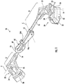
- FIG. 1 illustrates a lawn tool, such as a trimmer 10, having a trigger portion 12 supported on an upper boom (or first boom) 14 and a head portion 16 supported on a lower boom (or second boom) 18.
- the upper and lower booms 14, 18 are connected coaxially about a central longitudinal axis A, as will be described in greater detail below.
- the trimmer 10 is a hand-held powered trimmer.
- the trimmer 10 may be a different type of powered trimmer and, for example, may include a frame and wheels for movement over the ground.
- the head portion 16 includes a cutting head 20 driven to rotate about a cutting head axis B by a motor 22, such as an electric motor, etc.
- the axis B is transverse to the central longitudinal axis A (and therefore also to the lower boom 18). For example, an angle between 0 and 90 degrees is included between the axes A and B, or more specifically the angle is between 30 and 60 degrees.
- the cutting head 20 includes at least one cutter 24 extending generally radially from the cutting head 20 with respect to the axis B. Two cutters 24 are illustrated in FIG. 1 ; however, one, three, or more cutters 24 may be employed in other embodiments. In the illustrated embodiment, the cutter 24 includes string or trimmer line.
- the cutter 24 may include a blade, a sickle, a wire, or other suitable cutting implement.
- the cutting head 20 may include a spool (not shown) having a length of cutting line wound thereabout.
- the cutting head 20 may employ a bump-feed type spool, an auto-feed type spool, a fixed line spool, etc.
- the head portion 16 also includes a guard 26 disposed generally between the motor 22 and the cutting head 20.
- the guard 26 includes an arcuate portion 28 having a depending skirt 30 for covering a circumferential periphery of the cutter 24 during rotation thereof.
- the trigger portion 12 includes a main handle 32 having a grip portion 34 for controlling the trimmer 10.
- a trigger 36 is disposed proximate the grip portion 34 for activating the motor 22.
- the trigger 36 and grip portion 34 are configured in a pistol-grip type configuration in which the grip portion 34 is disposed transverse to the axis A of the upper boom 14.
- the trigger 36 is movable by an operator between an ON position in which the motor 22 is activated and an OFF position in which the motor 22 is not activated.
- the trigger portion 12 also includes a power source 38 operatively coupled to power the motor 22 when the trigger 36 is in the ON position.
- the power source 38 may include a battery, batteries, or a battery pack as illustrated.
- the trimmer 10 may be powered by other power sources 38, such as a cord providing AC power (e.g., from a wall outlet), solar cells, a fuel cell, etc.
- the trimmer 10 includes an electrical connection 40 ( FIG. 2 ) between the power source 38 and the motor 22.
- the electrical connection 40 may include wires, such as insulated electrical wires, which pass through the inside of the upper and lower booms 14, 18 from the power source 38 to the motor 22.
- the electrical connection 40 may be integrated into the upper and lower booms 14, 18 such that the connection is made both electrically and mechanically when the upper and lower booms 14, 18 are coupled.
- the electrical connection 40 may include electrical traces of conductive material, or wires, integrated into the upper and lower booms 14, 18 at the interface of the upper and lower booms 14, 18 in which the electrical traces or wires from the upper and lower booms 14, 18 engage, forming an electrical connection between the upper and lower booms 14, 18 when coupled.
- the battery and motor may both be disposed on the lower boom 18 such that the electrical connection 40 does not pass from the upper boom 14 to the lower boom 18.
- the trimmer 10 may include gasoline powered engine driving a flexible shaft, as will be described in greater detail below with respect to FIGS. 12-13 .
- the upper and lower booms 14, 18 mate at an interface 42 in a coaxial fashion about the axis A.
- the interface 42 includes a receiving portion 44 on the upper boom 14 having a larger diameter than the lower boom 18.
- the receiving portion 44 receives a distal end portion 46 of the lower boom 18 just radially inwards thereof, fitting together in close contact.
- the lower boom 18 may include the larger-diameter receiving portion for receiving the upper boom 14.
- the receiving portion 44 includes a slot 48 extending from a distal end 50 of the upper boom 14 towards the trigger portion 12 generally axially, parallel to the axis A.
- a coupler 52 is disposed coaxially about the interface 42 of the upper and lower booms 14, 18.
- the coupler 52 receives the interface 42 of the upper and lower booms 14, 18.
- the coupler 52 includes a collar 54 of generally cylindrical body construction disposed circumferentially and coaxially about the interface 42.
- the collar 54 includes apertures 56a ( FIG. 5 ) passing radially through the generally cylindrical body.
- the collar 54 includes three apertures 56a.
- the collar 54 may have one, two, four, or more apertures 56a.
- the receiving portion 44 may have corresponding apertures 56b ( FIG. 2 ). Biased locating pins (not shown) may be disposed in the apertures 56a, 56b.
- the biased locating pins which may be springloaded radially outward with respect to axis A by a biasing mechanism (not shown), may fasten and/or locate the upper and lower booms 14, 18 with respect to each other and with respect to the coupler 52.
- a biasing mechanism (not shown)
- other suitable detent mechanisms may be employed.
- no locating pins or other detent mechanisms need be employed.
- the coupler 52 also includes first and second lobes 58a, 58b extending from the collar 54 in parallel.
- a gap 60 is defined between the first and second lobes 58a, 58b and extends through the collar 54 such that the collar 54 has a circumferential break and does not form a complete annular ring, thereby providing circumferential flexion of the coupler 52.
- the slot 48 of the receiving portion 46 When assembled, the slot 48 of the receiving portion 46 generally aligns with the gap 60.
- a passage 62 defining an axis C extends through both lobes 58a, 58b and receives a bolt 64, or other fastener or pin, therethrough.
- Each of the lobes 58a, 58b is symmetrical about the gap 60. As such, it should be understood that only one lobe need be described herein as each lobe includes the same features facing opposite directions about the gap 60. Thus, like features of each lobe are given the same reference numeral herein.
- the lobes 58a, 58b each include lobe ramp surfaces 66 disposed annularly around the axis C.
- the lobe ramp surfaces 66 face outwardly away from the gap 60, generally axially with respect to the axis C.
- three lobe ramp surfaces 66 are disposed around the axis C, each lobe ramp surface 66 having a slope extending from a first axial position 68 with respect to the axis C to a second axial position 70 with respect to the axis C ( FIG. 6 ).
- the second axial position 70 is further away from the gap 60 in the corresponding axial direction than the first axial position 68.
- a different number of lobe ramp surfaces 66 such as one, two, four, or more may be employed.
- the lobe ramp surfaces 66 are surrounded by a cylindrical projection 72 having a gear 74 extending therefrom.
- the gear 74 includes asymmetrical teeth 76.
- the gear 74 includes a generally arcuate projection 78 supporting the teeth 76.
- the gear 74 may be generally circular with the teeth 76 arranged around the gear 74, or have any other suitable arrangement of the asymmetrical teeth 76.
- the coupler 52 may have other configurations.
- other clamping mechanisms such as the clamping mechanism shown in FIGS. 17-21 and described with regard to the coupler 52" below, may be employed.
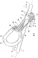
- a handle lever 80 is movably coupled to the coupler 52 and is rotatable about the axis C between a non-clamping position ( FIGS. 1 and 3-4 ) and a clamping position ( FIGS. 9-10 ).
- the handle lever 80 includes a handle portion 82 and a lever portion 84.
- the handle portion 82 provides a grip surface 86 and in the illustrated embodiment has a generally U-shaped configuration. In other embodiments, the handle portion 82 may have any other suitable shape, such as annular, L-shaped, straight, etc.
- the lever portion 84 is fixedly coupled to the handle portion 82, e.g., by way of fasteners 88 such as screws, or any other suitable connector.
- the lever portion 84 includes first and second lever arms 90a, 90b extending away from the handle portion 82 in parallel.
- Each lever arm 90a, 90b is movably coupled to one of the lobes 58a, 58b (respectively) of the coupler 52.
- the lever arms 90a, 90b are also symmetrical about the gap 60 and corresponding features of each lever arm 90a, 90b will be given the same reference numeral herein.
- the lever arms 90a, 90b are rotatably coupled to the coupler 52 for rotation about the axis C by way of the bolt 64 passing through a boss 92 in each of the lever arms 90a, 90b.
- each lever arm 90a, 90b includes lever ramp surfaces 94 disposed annularly around the axis C and around the boss 92.
- the lever ramp surfaces 94 face inwards towards the gap 60, generally axially with respect to the axis C.
- three lever ramp surfaces 94 are disposed around the axis C on each lever arm 90a, 90b, each lever ramp surface 94 having a slope extending from a third axial position 96 with respect to the axis C to a fourth axial position 98 with respect to the axis C.
- the third axial position 96 is further away from the gap 60 in the corresponding axial direction along axis C than the fourth axial position 98.
- lever ramp surfaces 94 When coupled to the coupler 52, the lever ramp surfaces 94 face the lobe ramp surfaces 66 and engage each other in a camming relationship therewith during rotation of the handle lever 80.
- the handle lever 80 also includes a slider 100 slidably mounted in the lever portion 84 for linear movement between a ratchet position (shown in FIG. 9 ) and a release position (not shown).
- the slider 100 is biased within the lever portion 84 to the ratcheting position by a biasing member 102 ( FIG. 4 ), such as a spring or other suitable member such as elastic material, etc.
- the biasing member 102 is a coil spring, but may be a leaf spring or other type of spring in other embodiments.
- the slider 100 includes an actuator 104 protruding from the lever portion 84 to an exterior of the trimmer 10 for engagement by an operator's hand or finger to push the slider 100 from the ratchet position to the release position against the bias of the biasing member 102. Without a force applied by the operator against the bias of the biasing member 102, the slider 100 is normally in the ratchet position from a force applied by the biasing member.
- the slider 100 includes first and second pawl arms 106a, 106b extending away from the actuator 104 in parallel with each other and in parallel with the lever arms 90a, 90b.
- the pawl arms 106a, 106b are generally symmetrical about the gap 60, as described above with respect to the lever arms 90a, 90b and the lobes 58a, 58b, and like features of the pawl arms 106a, 106b are given the same reference numerals herein.
- Each of the pawl arms 106a, 106b includes a beveled tip 108 at a distal end thereof, the beveled tip 108 configured to engage the asymmetrical teeth 76 of the gear 74 in a ratcheting relationship to form a pair of ratcheting assemblies.
- the beveled tip 108 engages and slides against sloped sides 110 ( FIG. 5 ) of the asymmetrical teeth 76 when the handle lever 80 is rotated in a first direction 112 ( FIGS. 4 and 9 ) relative to the coupler 52.
- the beveled tip 108 is fixed between asymmetrical teeth 76 against a steeply sloped side 114 ( FIG.
- the handle lever 80 is rotatable in the first direction 112 in a ratcheting relationship with the coupler 52 and is not rotatable in the second direction 116 when the slider 100 is in the ratchet position.
- the slider 100 is moved to the release position (not shown), the beveled tips 108 are pulled away from the gear 74 and out of engagement with the asymmetrical teeth 76, thus releasing the handle lever 80 such that the handle lever 80 can be rotated in the second direction 116.
- FIGS. 12-15 illustrate another embodiment of the lawn tool, such as a trimmer 10', with another embodiment of a handle lever 80' and coupler 52'.
- Like parts are labeled in FIGS. 12-15 with the same reference numerals used above followed by the prime symbol (') and need not be described again as reference is hereby made to the description above, while different features are described below.
- the trimmer 10' has a trigger portion 12' supporting an engine 118, such as a two-cycle gas engine, a gasoline-powered engine.
- the engine 118 may include a 25 cc gasoline-powered internal combustion engine, or other suitable type of engine.
- the trimmer 10' includes a string trimmer head portion 16', which is similar to the cutting head 16 described above and need not be described again.
- the trigger portion 12' with engine 118 is operatively coupled to the head portion 16' by upper and lower drive shafts 120, 122 disposed in the upper and lower booms 14', 18', respectively.
- the upper and lower drive shafts 120, 122 are coupled to each other for common rotation by way of a keyed connection (such as a square shaft for torque transmission) and/or by way of the handle lever 80' and coupler 52'.
- the upper and lower drive shafts 120, 122 are flexible drive shafts and may be formed from a bundle of entwined wires formed from steel, copper alloys, or other suitable material.
- the coupler 52' is substantially the same as the coupler 52 described above.
- the handle lever 80' is substantially the same as the handle lever 80 described above except the slider 100 is divided into an actuator portion 124 and first and second pawl arms 106' (the second pawl arm is not shown), each formed as a separate piece.
- the actuator portion 124, the first pawl arm 106', and the second pawl arm (not shown) have mirror symmetry about the gap (as discussed above) and any description of one side of the actuator portion 124 and the first pawl arm 106' applies to the opposite side of the actuator portion 124 and the second pawl arm in a mirrored relationship.
- the actuator portion 124 includes an actuator 104' protruding from a housing 126 of the handle lever 80'.
- the actuator portion 124 is rotatably mounted about a pivot axis D with the actuator 104' extending radially in one direction and a yoke 128 (with a first yoke arm 130 shown in FIG. 15 and a second yoke arm being a mirror image of the first yoke arm 130 and not shown) extending in another direction.
- the yoke 128 is operatively coupled to push and pull the first pawl arm 106' into and out of engagement with the gear 74' by way of a post 132 extending from the pawl arm 106'.
- the first pawl arm 106' and the second pawl arm are each biased towards the gear 74'.
- the first pawl arm 106' and the second pawl arm each include a spring pocket 134 and a spring 136.
- other suitable biasing members may be employed.
- first pawl arm 106' and the second pawl arm translate in a linear fashion towards the gear 74' by the biasing force of the spring 136 and away from the gear 74' in response to pivoting motion of the yoke 128.
- the yoke 128 is also biased by the spring 136 by engagement between the yoke 128 and posts 132.
- the yoke 128 is pivotable about the axis D by pushing the actuator 104' towards the coupler 52' against the bias of the spring 136.
- an operator mates the upper and lower booms 14, 18 by inserting the lower boom 14 into the upper boom 18 with the handle lever 80 in the non-clamping position ( FIGS. 3-4 ).
- the operator grips the handle portion 82 and pulls the handle lever 80 in the first direction 112 towards the clamping position ( FIGS. 9-11 ).
- the handle lever 80 rotates about the axis C in the first direction 112.
- the pawl arms 106a, 106b slide and ratchet against the gear 74, and the lever ramp surfaces 94 engage the lobe ramp surfaces 66 closer to the fourth axial position 98 such that the lever ramp surfaces 94 push inwardly on the coupler 52, as illustrated in FIG.
- the bolt 64 holds the lever arms 90a, 90b together and inhibits separation of the handle arms 90a, 90b from each other such that force is directed inwardly by engagement of the ramp surfaces 66, 94.
- the inward force exerted by the rotation of the lever ramp surfaces 94 in the first direction 112 acts as a clamping force on the coupler 52.
- the clamping force acts to reduce the size of the gap 60 and shorten the circumference (or cylindrical diameter) of the coupler 52 and of the receiving portion 44 by a small amount.
- the coupler 52 and the receiving portion 44 tighten around the distal end portion 46 of the lower boom 18, thereby clamping the upper and lower booms 14, 18 together.
- the handle lever 80 stays in the clamping position on its own accord due to the asymmetrical configuration of the teeth 76, which inhibits sliding of the beveled tips 108 of the pawl arms 106a, 106b in the second direction. If a force is exerted on the handle lever 80 in the second direction 116, the beveled tips 108 of the slider 100 engage the steeper sloped side 114 of the adjacent asymmetrical tooth 76 to inhibit movement of the handle lever 80.
- the handle lever 80 While the handle lever 80 is in the clamping position, the upper and lower booms 14, 18 are fixedly coupled and the trimmer motor 22 (or engine 118) may be actuated by the operator gripping the main handle 32 and pulling the trigger 36. Thus, the main handle 32 is used as a primary grip. The operator may use the handle portion 82 of the handle lever 80 as a secondary grip to further balance and manipulate the trimmer 10 during a cutting operation.
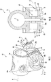
- FIGS. 17-21 illustrate yet another embodiment of a coupler 52". Like parts are labeled in FIGS. 17-21 with the same reference numerals used above followed by the double prime symbol (") and need not be described again as reference is hereby made to the description above, while different features are described below.
- the coupler 52" includes a collar 54" defining a member receiving passage as described above.
- the member receiving passage extends along the central longitudinal axis A.
- the coupler 52" includes first and second lobes 58a", 58b" extending outwardly from the collar 54".
- the first lobe 58a" includes a first cylindrical projection 72" extending therefrom.
- the first cylindrical projection 72" extends from the first lobe 58a" in a direction parallel to the axis C of the passage 62" that is defined in the first lobe.
- the passage 62" is non-threaded through the first lobe 58a".
- a plurality of first teeth 76" extend radially inwardly from the first cylindrical projection 72".
- Each of the first teeth 76" are bilaterally asymmetrical as described above.
- the second lobe 58b" includes at least one second lobe ramp surface 150.
- the passage 62" is also defined in the second lobe 58b".
- the second lobe ramp surface 150 forms a female thread of the second lobe 58b" about the passage 62".
- a rotatable knob 152 includes a first lever arm 90a" and a shank portion 154 connected to the first lever arm.
- the shank portion 154 includes a lever ramp surface 94" forming a male thread thereabout.
- the male thread of the shank portion 154 corresponds to the female thread of the second lobe 58b".
- the first lever arm 90a" of the rotatable knob 152 is rotatable about an axis C of the passage 62". Rotation of the rotatable knob 152 in the first direction 112" about the first axis C brings the first lobe 58a" and the second lobe 58b" toward each other.
- a first pawl arm 106a" is resiliently trapped in the rotatable knob 152.
- the first pawl arm 106a” is movably connected to the first lever arm 90a".
- the first pawl arm 106a” includes a beveled tip 108" biased into engagement with the first teeth 76".
- the first pawl arm 106a” allows ratcheting rotation of the rotatable knob 152 about the first axis C in the first direction 112", but the beveled tip 108" of the first pawl arm catches in the first teeth 76" to prevent rotation of the rotatable knob about the first axis in the second direction 116".
- the coupler 52" may also include a second pawl arm 106b".
- the first and second pawl arms 106a", 106b" are connected to each other as a single unitary piece.
- This piece is resiliently trapped in the rotatable knob 152.
- the piece includes two biasing members (shown as resilient clip members) 156 that ride in two respective clip channels 158 of the rotatable knob 152. Once fully inserted in the rotatable knob 152, the resilient clip members 156 snap outwardly to be trapped between the rotatable knob and the first lobe 58a". The resilient clip members 156 are not long enough to interfere with the first teeth 76".
- the resilient clip members 156 are pressed radially inward such that they again occupy the clip channels 158 of the rotatable knob.
- the first and second pawl arms 106a", 106b" are then moved away from the first teeth 76" in a direction generally parallel to the first axis C.
- the rotatable knob 152 is then rotated in the second direction 116" to move the first and second lobes 58a", 58b" away from each other.
- a fastener 64" extends through the passage 62" and longitudinally through the shank portion 154 of the rotatable knob 152.
- the fastener 64" couples the first lever arm 90a" of the rotatable knob 152 to the first and second lobes 58a", 58b" such that the lever ramp surface 94" is in camming engagement with the second lobe ramp surface 150.
- This fastener 64" maintains the components in close enough relationship such that the threads 94", 150 engage each other and the first pawl arm 106a" engages the first teeth 76".
- an operator mates the upper and lower booms 14, 18 by inserting the lower boom 14 into the upper boom 18 with the coupler 52" receiving the booms through the collar 54" along the central longitudinal axis A.
- the rotatable knob 152 and the shank portion 154 of the knob are in a position such that the first and second lobes 58a", 58b" are spaced apart from each other enough to allow the coupler 52" to loosely receive the booms 14, 18.
- the operator twists the rotatable knob 152 in a first direction, for instance, clockwise.
- This rotation of the rotatable knob 152 causes the shank portion 154, which includes the lever ramp surface 94" in the form of a male thread, to threadingly engage the second lobe ramp surface 150, thereby moving the first and second lobes toward each other 58a", 58b".
- the pawl arms 106a", 106b" engage the teeth 76" of the first lobe 58a" to allow ratcheting of the knob relative to the first lobe as the knob is rotated in the first direction.
- the ratcheting engagement between the pawl arms 106a", 106b” and the teeth 76" prevents the knob 152 from rotating relative to the first lobe 58a" in the second direction.
- the operator presses the resilient clip members 156 radially inwardly to allow the pawl arms 106a", 106b" to disengage the teeth 76" by sliding axially along the axis C of the passage 62".
- the rotatable knob 152 may be freely rotated by the user in the second direction to loosen the collar 54", thereby moving the lobes 58a", 58b" apart from each other.
- coupler 52, 52, 52" are described herein with respect to a lawn tool such as a trimmer, it should be understood that the coupler may be employed on any other lawn tool having an elongated boom or wand, such as pruners, loppers, shears, edgers, brush cutters, saws, mowers, hedge trimmers, blowers, vacuums, etc.
- the coupler 52, 52', 52" may be employed on any other device having an elongated boom or wand, such as metal detectors, sweepers, polishers, brushes, cleaners, tillers/cultivators, etc. In some embodiments (e.g., as shown in FIG.
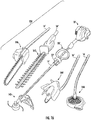
- FIG. 16 illustrates a landscape trimmer kit 138 having a string trimmer attachment 140 (e.g., the cutting head 20' with cutter 24'), a hedge trimmer attachment 142, an edger attachment 144, a pole saw (or pruner) attachment 146, and a blower attachment 148.
- Each attachment includes a lower boom 18 that couples with the upper boom 14 by way of any of the embodiments of the coupling and release mechanisms discussed herein.
- the operator may change between the various attachments 140, 142, 144, 146, 148 described above couple a desired one of the attachments 140, 142, 144, 146, 148 by inserting the respective lower boom 18, 18' and moving the coupler 52" to the clamping position.
- the invention may provide, among other things, a lawn tool or other device having upper and lower booms 14, 14', 18, 18' couplable by way of a clamping mechanism, such as the coupler 52, 52', 52".
Abstract
Description
- This application claims benefit of co-pending
U.S. Provisional Patent Application No. 62/637,167, filed on March 1, 2018 - The present invention relates to landscape trimmers, and more particularly, to a coupler for connecting an upper boom and a lower boom of the trimmer.
- Generally, landscape trimmers are used to cut grass, weeds, or other vegetation, and are often used to edge around trees, near fences and walls, and along landscape borders. Conventional landscape trimmers include an elongated shaft with a rotating element or gear head near the end of the elongated shaft, and a spool, string head, or blade(s) is attached to the gear head. Typically, the gear head includes a monofilament line (i.e., trimmer line) or blade(s) that is rotated by the gear head for cutting and trimming along landscaped areas, fences, and walls.
- In a first aspect of the invention, there is provided a coupler for joining two members of a split-boom power tool. The coupler includes a collar defining a member receiving passage. A first lobe and a second lobe extend outwardly from the collar. The first lobe includes at least one lobe ramp surface, a cylindrical projection extending from the first lobe, and a gear extending from the cylindrical projection. The gear includes gear teeth. A passage is defined in the first lobe and the second lobe and having a first axis. A lever arm is rotatable about the first axis. The lever arm includes at least one lever ramp surface. A pawl arm is movably connected to the lever arm. The pawl arm includes a portion biased into engagement with the gear teeth. A fastener extends through the passage. The fastener couples the lever arm to the first lobe such that the lever ramp surface is in camming engagement with the lobe ramp surface. Rotation of the lever arm about the first axis in a first direction brings the first lobe and the second lobe toward each other.
- The cylindrical projection may radially surround at least a portion of the lobe ramp surface.
- The pawl arm may ratchet relative to the gear in the first direction.
- The pawl arm may catch in the gear teeth when the pawl arm is engaged with the gear teeth and the lever arm experiences a rotational force in a second direction about the first axis, thereby preventing rotation of the lever arm in the second direction.
- The second direction may be opposite the first direction.
- The coupler may further comprise an actuator operably coupled to the pawl arm.
- Actuation of the actuator may move the pawl arm out of engagement with the gear teeth.
- The actuator may be formed of a single unitary piece with the pawl arm.
- The coupler may further comprise: a yoke arm operatively coupled to the actuator; a post extending from the pawl arm.
- The actuator and the yoke arm may be rotatably mounted about a pivot axis.
- Rotation of the actuator may cause rotation of the yoke arm about the pivot axis.
- The yoke arm may engage the post.
- Rotation of the yoke arm about the pivot axis may cause linear movement of the pawl arm.
- The collar may include a circumferential break.
- A gap may be defined between the first lobe and the second lobe.
- The coupler may further comprise a handle lever including a handle portion and a lever portion, and the lever portion may include the lever arm.
- The lever arm may be a first lever arm. The coupler may further comprise: a second lever arm rotatable about the first axis, the second lever arm including at least one lever ramp surface including an axially tallest portion.
- The second lobe may include at least one lobe ramp surface, the lobe ramp surface of the second lobe including an axially tallest portion.
- The fastener may couple the second lever arm to the second lobe such that the lever ramp surface of the second lever arm is in camming engagement with the lobe ramp surface of the second lobe.
- Rotation of the second lever arm about the first axis in the first direction may bring the axially tallest portion of the lobe ramp surface of the second lobe and the axially tallest portion of the lever ramp surface of the second lever arm toward each other.
- In a second aspect of the invention, there is provided a coupler for joining two members of a split-boom power tool. The coupler includes a collar defining a member receiving passage. A first lobe and a second lobe extend outwardly from the collar. One of the first lobe and the second lobe includes a plurality of teeth extending radially therefrom. One of the first lobe and the second lobe includes at least one lobe ramp surface. A passage is defined in the first lobe and the second lobe. The passage defines a first axis. A lever arm is rotatable about the first axis. The lever arm includes at least one lever ramp surface. A pawl arm is movably connected to the lever arm. The pawl arm includes a portion that is biased into engagement with the teeth. A fastener extends through the passage. The fastener couples the lever arm to the first lobe and the second lobe. The lever ramp surface is in camming engagement with the lobe ramp surface. Rotation of the lever arm about the first axis in a first direction brings the first lobe and the second lobe toward each other.
- The pawl arm may ratchet relative to the teeth in the first direction.
- The pawl arm may catch in the teeth when the pawl arm is engaged with the teeth and the lever arm experiences a rotational force in a second direction about the first axis, thereby preventing rotation of the lever arm in the second direction.
- The second direction may be opposite the first direction.
- The coupler may further comprise a knob including the lever arm and a shank portion connected to the lever arm, the lever ramp surface connected to the shank portion.
- The pawl arm may be resiliently trapped in the knob.
- The lobe ramp surface may form a female thread.
- The at least one lever ramp may form a corresponding male thread.
- The fastener may further extend longitudinally through the shank portion of the knob.
- The passage through the first lobe may be non-threaded.
- The first lobe may include the plurality of teeth.
- The second lobe may include the at least one lobe ramp surface.
- In a third aspect of the invention, there is provided a coupler for joining two members of a split-boom power tool. The coupler includes a collar defining a member receiving passage. A lever arm is rotatable relative to the collar in a first direction to constrict the member receiving passage. The lever arm is also rotatable relative to the collar in a second direction to expand the member receiving passage. A ratcheting assembly engages the collar with the lever arm. The ratcheting assembly allows rotation of the lever arm relative to the collar in the first direction. The ratcheting assembly prevents rotation of the lever arm relative to the collar in the second direction. A biasing member maintains the collar and the lever arm in engagement. Actuation against the biasing member removes the collar and the lever arm from engagement. This removal allows the lever arm to be freely rotated relative to the collar in the second direction.
- The ratcheting assembly may include a pawl arm and a plurality of teeth.
- The biasing member may maintain the pawl arm in engagement with the plurality of teeth.
- The coupler may further comprises an actuator connected to the pawl arm.
- Actuation of the actuator against a bias of the biasing member may move the pawl arm out of engagement with the plurality of teeth.
- The biasing member may include a resilient clip member.
- The resilient clip member may be connected to the pawl arm.
- Actuation against a bias of the resilient clip member may allow removal of the pawl arm from engagement with the plurality of teeth.
- According to another aspect of the invention there is provided a split-boom power tool comprising: a first boom member and a second boom member, the second boom member removably connectable coaxially to the first boom member at an interface; and the coupler of any one of aspects of the invention discussed above for joining the first boom member and the second boom member, wherein the collar of the coupler is configured to be disposed coaxially to the first boom member and the second boom member about the interface.
- Any of the optional features discussed above in relation to one aspect of the invention may, where appropriate, apply to any other aspect of the invention.
- Other features and aspects of the disclosure will become apparent by consideration of the detailed description and accompanying drawings.
-
-
FIG. 1 is a perspective view of a landscape trimmer according to one embodiment of the invention. -
FIG. 2 is a perspective partial view of an interface of upper and lower booms of the landscape trimmer shown inFIG. 1 , the upper boom being shown as transparent. -
FIG. 3 is a front perspective view of a handle lever with coupler shown inFIG. 1 , the handle lever being shown in a non-clamping position. -
FIG. 4 is a side view of the handle lever with coupler shown inFIG. 3 , with a portion of the handle lever shown as transparent. -
FIG. 5 is a rear perspective view of the coupler shown inFIGS. 1 ,3, and 4 . -
FIG. 6 is a front cross-section view of the coupler taken along line 6-6 inFIG. 5 . -
FIG. 7 is a perspective view of a portion of a lever arm shown inFIGS. 1 ,3, and 4 . -
FIG. 8 is an enlarged perspective view of a portion of the lever arm shown inFIG. 7 . -
FIG. 9 is a perspective view of the handle lever with coupler shown inFIGS. 1 ,3, and 4 having a portion of the handle lever removed, the handle lever being shown in a clamping position. -
FIG. 10 is a perspective view of the handle lever with coupler shown inFIG. 9 with the whole handle lever. -
FIG. 11 is a perspective cross-sectional view of the handle lever with coupler taken through line 11-11 inFIG. 9 . -
FIG. 12 is a perspective view of another embodiment of a landscape trimmer. -
FIG. 13 is a cross-sectional side view of the landscape trimmer taken along line 13-13 inFIG. 12 . -
FIG. 14 is a perspective view of a handle lever with coupler of the landscape trimmer shown inFIG. 12 , the handle lever being shown in a non-clamping position. -
FIG. 15 is a side view of the handle lever with coupler shown inFIG. 14 , with a portion of the handle lever housing removed. -
FIG. 16 is a perspective view of a landscape trimmer kit with attachments. -
FIG. 17 is a perspective view of another embodiment of a coupler to be positioned between a first boom and a second boom. -
FIG. 18 is an exploded perspective view of the coupler ofFIG. 17 . -
FIG. 19 is a front cross-section view of the coupler taken along line 19-19 inFIG. 17 . -
FIG. 20 is a side elevation view of the coupler ofFIG. 17 with a knob removed from the coupler. -
FIG. 21 is a side elevation view of components of the coupler ofFIG. 17 . - Before any embodiments of the invention are explained in detail, it is to be understood that the invention is not limited in its application to the details of construction and the arrangement of components set forth in the following description or illustrated in the following drawings. The invention is capable of other embodiments and of being practiced or of being carried out in various ways. Also, it is to be understood that the phraseology and terminology used herein is for the purpose of description and should not be regarded as limiting.
-
FIG. 1 illustrates a lawn tool, such as atrimmer 10, having atrigger portion 12 supported on an upper boom (or first boom) 14 and ahead portion 16 supported on a lower boom (or second boom) 18. The upper andlower booms trimmer 10 is a hand-held powered trimmer. In other embodiments (not shown), thetrimmer 10 may be a different type of powered trimmer and, for example, may include a frame and wheels for movement over the ground. - The
head portion 16 includes a cuttinghead 20 driven to rotate about a cutting head axis B by amotor 22, such as an electric motor, etc. The axis B is transverse to the central longitudinal axis A (and therefore also to the lower boom 18). For example, an angle between 0 and 90 degrees is included between the axes A and B, or more specifically the angle is between 30 and 60 degrees. The cuttinghead 20 includes at least onecutter 24 extending generally radially from the cuttinghead 20 with respect to the axis B. Twocutters 24 are illustrated inFIG. 1 ; however, one, three, ormore cutters 24 may be employed in other embodiments. In the illustrated embodiment, thecutter 24 includes string or trimmer line. In other embodiments, thecutter 24 may include a blade, a sickle, a wire, or other suitable cutting implement. In yet other embodiments, the cuttinghead 20 may include a spool (not shown) having a length of cutting line wound thereabout. The cuttinghead 20 may employ a bump-feed type spool, an auto-feed type spool, a fixed line spool, etc. Thehead portion 16 also includes aguard 26 disposed generally between themotor 22 and the cuttinghead 20. Theguard 26 includes anarcuate portion 28 having a dependingskirt 30 for covering a circumferential periphery of thecutter 24 during rotation thereof. - The
trigger portion 12 includes amain handle 32 having agrip portion 34 for controlling thetrimmer 10. Atrigger 36 is disposed proximate thegrip portion 34 for activating themotor 22. In the illustrated embodiment, thetrigger 36 andgrip portion 34 are configured in a pistol-grip type configuration in which thegrip portion 34 is disposed transverse to the axis A of theupper boom 14. However, other configurations may be employed. Thetrigger 36 is movable by an operator between an ON position in which themotor 22 is activated and an OFF position in which themotor 22 is not activated. Thetrigger portion 12 also includes apower source 38 operatively coupled to power themotor 22 when thetrigger 36 is in the ON position. Thepower source 38 may include a battery, batteries, or a battery pack as illustrated. However, in other embodiments, thetrimmer 10 may be powered byother power sources 38, such as a cord providing AC power (e.g., from a wall outlet), solar cells, a fuel cell, etc. - The
trimmer 10 includes an electrical connection 40 (FIG. 2 ) between thepower source 38 and themotor 22. Theelectrical connection 40 may include wires, such as insulated electrical wires, which pass through the inside of the upper andlower booms power source 38 to themotor 22. In other embodiments, theelectrical connection 40 may be integrated into the upper andlower booms lower booms electrical connection 40 may include electrical traces of conductive material, or wires, integrated into the upper andlower booms lower booms lower booms lower booms lower boom 18 such that theelectrical connection 40 does not pass from theupper boom 14 to thelower boom 18. In further embodiments, thetrimmer 10 may include gasoline powered engine driving a flexible shaft, as will be described in greater detail below with respect toFIGS. 12-13 . - As illustrated in
FIG. 2 , the upper andlower booms interface 42 in a coaxial fashion about the axis A. In the illustrated embodiment, theinterface 42 includes a receivingportion 44 on theupper boom 14 having a larger diameter than thelower boom 18. The receivingportion 44 receives a distal end portion 46 of thelower boom 18 just radially inwards thereof, fitting together in close contact. In other embodiments, thelower boom 18 may include the larger-diameter receiving portion for receiving theupper boom 14. The receivingportion 44 includes aslot 48 extending from adistal end 50 of theupper boom 14 towards thetrigger portion 12 generally axially, parallel to the axis A. - As illustrated in
FIGS. 3-5 , acoupler 52 is disposed coaxially about theinterface 42 of the upper andlower booms coupler 52 receives theinterface 42 of the upper andlower booms coupler 52 includes acollar 54 of generally cylindrical body construction disposed circumferentially and coaxially about theinterface 42. Thecollar 54 includesapertures 56a (FIG. 5 ) passing radially through the generally cylindrical body. In the illustrated embodiment, thecollar 54 includes threeapertures 56a. However, in other embodiments, thecollar 54 may have one, two, four, ormore apertures 56a. The receivingportion 44 may havecorresponding apertures 56b (FIG. 2 ). Biased locating pins (not shown) may be disposed in theapertures lower booms coupler 52. In other embodiments, other suitable detent mechanisms may be employed. In yet other embodiments, no locating pins or other detent mechanisms need be employed. - The
coupler 52 also includes first andsecond lobes collar 54 in parallel. Agap 60 is defined between the first andsecond lobes collar 54 such that thecollar 54 has a circumferential break and does not form a complete annular ring, thereby providing circumferential flexion of thecoupler 52. When assembled, theslot 48 of the receiving portion 46 generally aligns with thegap 60. Apassage 62 defining an axis C extends through bothlobes bolt 64, or other fastener or pin, therethrough. Each of thelobes gap 60. As such, it should be understood that only one lobe need be described herein as each lobe includes the same features facing opposite directions about thegap 60. Thus, like features of each lobe are given the same reference numeral herein. - The
lobes gap 60, generally axially with respect to the axis C. In the illustrated embodiment, three lobe ramp surfaces 66 are disposed around the axis C, eachlobe ramp surface 66 having a slope extending from a firstaxial position 68 with respect to the axis C to a secondaxial position 70 with respect to the axis C (FIG. 6 ). The secondaxial position 70 is further away from thegap 60 in the corresponding axial direction than the firstaxial position 68. In other embodiments, a different number of lobe ramp surfaces 66, such as one, two, four, or more may be employed. - The lobe ramp surfaces 66 are surrounded by a
cylindrical projection 72 having agear 74 extending therefrom. Thegear 74 includesasymmetrical teeth 76. In the illustrated embodiment, thegear 74 includes a generallyarcuate projection 78 supporting theteeth 76. However, in other embodiments, thegear 74 may be generally circular with theteeth 76 arranged around thegear 74, or have any other suitable arrangement of theasymmetrical teeth 76. - In other embodiments, the
coupler 52 may have other configurations. For example, other clamping mechanisms, such as the clamping mechanism shown inFIGS. 17-21 and described with regard to thecoupler 52" below, may be employed. - With reference to
FIGS. 1 ,3-4 and9-10 , ahandle lever 80 is movably coupled to thecoupler 52 and is rotatable about the axis C between a non-clamping position (FIGS. 1 and3-4 ) and a clamping position (FIGS. 9-10 ). Thehandle lever 80 includes ahandle portion 82 and alever portion 84. Thehandle portion 82 provides agrip surface 86 and in the illustrated embodiment has a generally U-shaped configuration. In other embodiments, thehandle portion 82 may have any other suitable shape, such as annular, L-shaped, straight, etc. - The
lever portion 84 is fixedly coupled to thehandle portion 82, e.g., by way offasteners 88 such as screws, or any other suitable connector. Thelever portion 84 includes first andsecond lever arms handle portion 82 in parallel. Eachlever arm lobes coupler 52. As described above with respect to thelobes lever arms gap 60 and corresponding features of eachlever arm lever arms coupler 52 for rotation about the axis C by way of thebolt 64 passing through aboss 92 in each of thelever arms - As best illustrated in
FIGS. 7-8 , eachlever arm boss 92. The lever ramp surfaces 94 face inwards towards thegap 60, generally axially with respect to the axis C. In the illustrated embodiment, three lever ramp surfaces 94 are disposed around the axis C on eachlever arm lever ramp surface 94 having a slope extending from a thirdaxial position 96 with respect to the axis C to a fourthaxial position 98 with respect to the axis C. The thirdaxial position 96 is further away from thegap 60 in the corresponding axial direction along axis C than the fourthaxial position 98. In other embodiments, a different number of lever ramp surfaces 94, such as one, two, four, or more may be employed. When coupled to thecoupler 52, the lever ramp surfaces 94 face the lobe ramp surfaces 66 and engage each other in a camming relationship therewith during rotation of thehandle lever 80. - The
handle lever 80 also includes aslider 100 slidably mounted in thelever portion 84 for linear movement between a ratchet position (shown inFIG. 9 ) and a release position (not shown). Theslider 100 is biased within thelever portion 84 to the ratcheting position by a biasing member 102 (FIG. 4 ), such as a spring or other suitable member such as elastic material, etc. In the illustrated embodiment, the biasingmember 102 is a coil spring, but may be a leaf spring or other type of spring in other embodiments. Theslider 100 includes anactuator 104 protruding from thelever portion 84 to an exterior of thetrimmer 10 for engagement by an operator's hand or finger to push theslider 100 from the ratchet position to the release position against the bias of the biasingmember 102. Without a force applied by the operator against the bias of the biasingmember 102, theslider 100 is normally in the ratchet position from a force applied by the biasing member. - The
slider 100 includes first andsecond pawl arms actuator 104 in parallel with each other and in parallel with thelever arms pawl arms gap 60, as described above with respect to thelever arms lobes pawl arms pawl arms beveled tip 108 at a distal end thereof, thebeveled tip 108 configured to engage theasymmetrical teeth 76 of thegear 74 in a ratcheting relationship to form a pair of ratcheting assemblies. Specifically, thebeveled tip 108 engages and slides against sloped sides 110 (FIG. 5 ) of theasymmetrical teeth 76 when thehandle lever 80 is rotated in a first direction 112 (FIGS. 4 and9 ) relative to thecoupler 52. Thebeveled tip 108 is fixed betweenasymmetrical teeth 76 against a steeply sloped side 114 (FIG. 5 ) of the adjacentasymmetrical tooth 76 when a force is applied to rotate thehandle lever 80 in asecond direction 116. Thus, thehandle lever 80 is rotatable in thefirst direction 112 in a ratcheting relationship with thecoupler 52 and is not rotatable in thesecond direction 116 when theslider 100 is in the ratchet position. When theslider 100 is moved to the release position (not shown), thebeveled tips 108 are pulled away from thegear 74 and out of engagement with theasymmetrical teeth 76, thus releasing thehandle lever 80 such that thehandle lever 80 can be rotated in thesecond direction 116. -
FIGS. 12-15 illustrate another embodiment of the lawn tool, such as a trimmer 10', with another embodiment of a handle lever 80' and coupler 52'. Like parts are labeled inFIGS. 12-15 with the same reference numerals used above followed by the prime symbol (') and need not be described again as reference is hereby made to the description above, while different features are described below. - With reference to
FIGS. 12-13 , the trimmer 10' has a trigger portion 12' supporting anengine 118, such as a two-cycle gas engine, a gasoline-powered engine. For example, theengine 118 may include a 25 cc gasoline-powered internal combustion engine, or other suitable type of engine. The trimmer 10' includes a string trimmer head portion 16', which is similar to the cuttinghead 16 described above and need not be described again. The trigger portion 12' withengine 118 is operatively coupled to the head portion 16' by upper andlower drive shafts lower drive shafts lower drive shafts - With reference to
FIGS. 14-15 , the coupler 52' is substantially the same as thecoupler 52 described above. The handle lever 80' is substantially the same as thehandle lever 80 described above except theslider 100 is divided into anactuator portion 124 and first and second pawl arms 106' (the second pawl arm is not shown), each formed as a separate piece. It should be understood that theactuator portion 124, the first pawl arm 106', and the second pawl arm (not shown) have mirror symmetry about the gap (as discussed above) and any description of one side of theactuator portion 124 and the first pawl arm 106' applies to the opposite side of theactuator portion 124 and the second pawl arm in a mirrored relationship. - The
actuator portion 124 includes an actuator 104' protruding from ahousing 126 of the handle lever 80'. Theactuator portion 124 is rotatably mounted about a pivot axis D with the actuator 104' extending radially in one direction and a yoke 128 (with afirst yoke arm 130 shown inFIG. 15 and a second yoke arm being a mirror image of thefirst yoke arm 130 and not shown) extending in another direction. Theyoke 128 is operatively coupled to push and pull the first pawl arm 106' into and out of engagement with the gear 74' by way of apost 132 extending from the pawl arm 106'. Theyoke 128, by way of the second yoke arm (not shown), is also operatively coupled to simultaneously push and pull the second pawl arm (not shown) into and out of engagement with the gear 74' by way of a post (not shown) in a mirrored fashion with respect to thefirst yoke arm 130. The first pawl arm 106' and the second pawl arm are each biased towards the gear 74'. For example, the first pawl arm 106' and the second pawl arm each include aspring pocket 134 and aspring 136. However, in other embodiments, other suitable biasing members may be employed. Thus, the first pawl arm 106' and the second pawl arm translate in a linear fashion towards the gear 74' by the biasing force of thespring 136 and away from the gear 74' in response to pivoting motion of theyoke 128. Theyoke 128 is also biased by thespring 136 by engagement between theyoke 128 and posts 132. Theyoke 128 is pivotable about the axis D by pushing the actuator 104' towards the coupler 52' against the bias of thespring 136. - In operation, an operator mates the upper and
lower booms lower boom 14 into theupper boom 18 with thehandle lever 80 in the non-clamping position (FIGS. 3-4 ). The operator grips thehandle portion 82 and pulls thehandle lever 80 in thefirst direction 112 towards the clamping position (FIGS. 9-11 ). During movement towards the clamping position, thehandle lever 80 rotates about the axis C in thefirst direction 112. During movement in thefirst direction 112, thepawl arms gear 74, and the lever ramp surfaces 94 engage the lobe ramp surfaces 66 closer to the fourthaxial position 98 such that the lever ramp surfaces 94 push inwardly on thecoupler 52, as illustrated inFIG. 11 . Thebolt 64 holds thelever arms handle arms first direction 112 acts as a clamping force on thecoupler 52. The clamping force acts to reduce the size of thegap 60 and shorten the circumference (or cylindrical diameter) of thecoupler 52 and of the receivingportion 44 by a small amount. Thus, thecoupler 52 and the receivingportion 44 tighten around the distal end portion 46 of thelower boom 18, thereby clamping the upper andlower booms - The
handle lever 80 stays in the clamping position on its own accord due to the asymmetrical configuration of theteeth 76, which inhibits sliding of thebeveled tips 108 of thepawl arms handle lever 80 in thesecond direction 116, thebeveled tips 108 of theslider 100 engage the steepersloped side 114 of the adjacentasymmetrical tooth 76 to inhibit movement of thehandle lever 80. - While the
handle lever 80 is in the clamping position, the upper andlower booms main handle 32 and pulling thetrigger 36. Thus, themain handle 32 is used as a primary grip. The operator may use thehandle portion 82 of thehandle lever 80 as a secondary grip to further balance and manipulate thetrimmer 10 during a cutting operation. - To release the
handle lever 80 for movement in thesecond direction 116 back to the non-clamping position, the operator pushes theactuator 104 against the bias of the biasingmember 102 to linearly move theslider 100 away from thegear 74, thus pulling thebeveled tips 108 out of engagement with theasymmetrical teeth 76. - It should be understood that operation of the other embodiment of the trimmer 10' is the same as described above with respect to the
trimmer 10, except that to release the handle lever 80' for movement in the second direction 116' back to the non-clamping position, the operator pushes the actuator 104' towards the coupler 52' against the bias of thespring 136, which pivots theyoke 128, which in turn pulls the first and second pawl arms 106' away from the gear 74', thus pulling the beveled tips 108' out of engagement with the asymmetrical teeth 76'. -
FIGS. 17-21 illustrate yet another embodiment of acoupler 52". Like parts are labeled inFIGS. 17-21 with the same reference numerals used above followed by the double prime symbol (") and need not be described again as reference is hereby made to the description above, while different features are described below. - With reference to
FIGS. 17 and18 , thecoupler 52" includes acollar 54" defining a member receiving passage as described above. The member receiving passage extends along the central longitudinal axis A. Thecoupler 52" includes first andsecond lobes 58a", 58b" extending outwardly from thecollar 54". - The
first lobe 58a" includes a firstcylindrical projection 72" extending therefrom. The firstcylindrical projection 72" extends from thefirst lobe 58a" in a direction parallel to the axis C of thepassage 62" that is defined in the first lobe. Thepassage 62" is non-threaded through thefirst lobe 58a". A plurality offirst teeth 76" extend radially inwardly from the firstcylindrical projection 72". Each of thefirst teeth 76" are bilaterally asymmetrical as described above. - The
second lobe 58b" includes at least one secondlobe ramp surface 150. Thepassage 62" is also defined in thesecond lobe 58b". The secondlobe ramp surface 150 forms a female thread of thesecond lobe 58b" about thepassage 62". - A
rotatable knob 152 includes afirst lever arm 90a" and ashank portion 154 connected to the first lever arm. Theshank portion 154 includes alever ramp surface 94" forming a male thread thereabout. The male thread of theshank portion 154 corresponds to the female thread of thesecond lobe 58b". Thefirst lever arm 90a" of therotatable knob 152 is rotatable about an axis C of thepassage 62". Rotation of therotatable knob 152 in thefirst direction 112" about the first axis C brings thefirst lobe 58a" and thesecond lobe 58b" toward each other. - A
first pawl arm 106a" is resiliently trapped in therotatable knob 152. Thefirst pawl arm 106a" is movably connected to thefirst lever arm 90a". Thefirst pawl arm 106a" includes abeveled tip 108" biased into engagement with thefirst teeth 76". Thefirst pawl arm 106a" allows ratcheting rotation of therotatable knob 152 about the first axis C in thefirst direction 112", but thebeveled tip 108" of the first pawl arm catches in thefirst teeth 76" to prevent rotation of the rotatable knob about the first axis in thesecond direction 116". As discussed above, thecoupler 52" may also include asecond pawl arm 106b". In the present embodiment of thecoupler 52", however, the first andsecond pawl arms 106a", 106b" are connected to each other as a single unitary piece. This piece, as discussed above, is resiliently trapped in therotatable knob 152. Particularly, the piece includes two biasing members (shown as resilient clip members) 156 that ride in tworespective clip channels 158 of therotatable knob 152. Once fully inserted in therotatable knob 152, theresilient clip members 156 snap outwardly to be trapped between the rotatable knob and thefirst lobe 58a". Theresilient clip members 156 are not long enough to interfere with thefirst teeth 76". - To rotate the
rotatable knob 152 freely in thesecond direction 116", theresilient clip members 156 are pressed radially inward such that they again occupy theclip channels 158 of the rotatable knob. In this radially inward position, the first andsecond pawl arms 106a", 106b" are then moved away from thefirst teeth 76" in a direction generally parallel to the first axis C. Therotatable knob 152 is then rotated in thesecond direction 116" to move the first andsecond lobes 58a", 58b" away from each other. - A
fastener 64" extends through thepassage 62" and longitudinally through theshank portion 154 of therotatable knob 152. Thefastener 64" couples thefirst lever arm 90a" of therotatable knob 152 to the first andsecond lobes 58a", 58b" such that thelever ramp surface 94" is in camming engagement with the secondlobe ramp surface 150. Thisfastener 64" maintains the components in close enough relationship such that thethreads 94", 150 engage each other and thefirst pawl arm 106a" engages thefirst teeth 76". - In operation, an operator mates the upper and
lower booms lower boom 14 into theupper boom 18 with thecoupler 52" receiving the booms through thecollar 54" along the central longitudinal axis A. Therotatable knob 152 and theshank portion 154 of the knob are in a position such that the first andsecond lobes 58a", 58b" are spaced apart from each other enough to allow thecoupler 52" to loosely receive thebooms collar 54" of thecoupler 52" has received thebooms rotatable knob 152 in a first direction, for instance, clockwise. This rotation of therotatable knob 152 causes theshank portion 154, which includes thelever ramp surface 94" in the form of a male thread, to threadingly engage the secondlobe ramp surface 150, thereby moving the first and second lobes toward each other 58a", 58b". In order to prevent inadvertent rotation of theknob 152 in the second direction, e.g. - counter-clockwise, thepawl arms 106a", 106b" engage theteeth 76" of thefirst lobe 58a" to allow ratcheting of the knob relative to the first lobe as the knob is rotated in the first direction. The ratcheting engagement between thepawl arms 106a", 106b" and theteeth 76" prevents theknob 152 from rotating relative to thefirst lobe 58a" in the second direction. - To release the
coupler 52" and thereby loosen thecollar 54" for detachment of thelower boom 14 from theupper boom 18, the operator presses theresilient clip members 156 radially inwardly to allow thepawl arms 106a", 106b" to disengage theteeth 76" by sliding axially along the axis C of thepassage 62". Once thepawl arms 106a", 106b" are clear of theteeth 76", therotatable knob 152 may be freely rotated by the user in the second direction to loosen thecollar 54", thereby moving thelobes 58a", 58b" apart from each other. - While the
coupler coupler FIG. 16 ), the above-mentioned implements may be interchangeable with thetrimmer head portion 16 by releasing thelower boom 18 and inserting a different lower boom having the different implement. For example,FIG. 16 illustrates alandscape trimmer kit 138 having a string trimmer attachment 140 (e.g., the cutting head 20' with cutter 24'), ahedge trimmer attachment 142, anedger attachment 144, a pole saw (or pruner)attachment 146, and ablower attachment 148. Each attachment includes alower boom 18 that couples with theupper boom 14 by way of any of the embodiments of the coupling and release mechanisms discussed herein. - The operator may change between the
various attachments attachments lower boom 18, 18' and moving thecoupler 52" to the clamping position. - Thus, the invention may provide, among other things, a lawn tool or other device having upper and
lower booms coupler - Various features of the invention are set forth in the following claims.
Claims (15)
- A coupler for joining two members of a split-boom power tool, the coupler comprising:a collar defining a member receiving passage;a first lobe extending outwardly from the collar, the first lobe including at least one lobe ramp surface;a cylindrical projection extending from the first lobe; anda gear extending from the cylindrical projection, the gear including gear teeth;a second lobe extending outwardly from the collar;a passage defined in the first lobe and the second lobe, the passage defining a first axis;a lever arm rotatable about the first axis, the lever arm including at least one lever ramp surface;a pawl arm movably connected to the lever arm, the pawl arm including a portion biased into engagement with the gear teeth;a fastener extending through the passage, the fastener coupling the lever arm to the first lobe such that the lever ramp surface is in camming engagement with the lobe ramp surface; andwherein rotation of the lever arm about the first axis in a first direction brings the first lobe and the second lobe toward each other.
- The coupler of claim 1, wherein the cylindrical projection radially surrounds at least a portion of the lobe ramp surface.
- The coupler of claim 1 or 2, whereinthe pawl arm ratchets relative to the gear in the first direction;the pawl arm catches in the gear teeth when the pawl arm is engaged with the gear teeth and the lever arm experiences a rotational force in a second direction about the first axis, thereby preventing rotation of the lever arm in the second direction; andthe second direction is opposite the first direction.
- The coupler of claim 3, further comprisingan actuator operably coupled to the pawl arm; andwherein actuation of the actuator moves the pawl arm out of engagement with the gear teeth; and, optionally, wherein the actuator is formed of a single unitary piece with the pawl arm.
- The coupler of claim 4, further comprisinga yoke arm operatively coupled to the actuator;a post extending from the pawl arm; andwhereinthe actuator and the yoke arm are rotatably mounted about a pivot axis;rotation of the actuator causes rotation of the yoke arm about the pivot axis;the yoke arm engages the post; androtation of the yoke arm about the pivot axis causes linear movement of the pawl arm.
- The coupler of any one of claims 1 to 5, wherein(i) the collar includes a circumferential break; and a gap is defined between the first lobe and the second lobe; and/or(ii) the coupler further comprises a handle lever including a handle portion and a lever portion, and the lever portion includes the lever arm.
- The coupler of any one of claims 1 to 6, wherein the lever arm is a first lever arm, and further comprisinga second lever arm rotatable about the first axis, the second lever arm including at least one lever ramp surface including an axially tallest portion; andwhereinthe second lobe includes at least one lobe ramp surface, the lobe ramp surface of the second lobe including an axially tallest portion;the fastener couples the second lever arm to the second lobe such that the lever ramp surface of the second lever arm is in camming engagement with the lobe ramp surface of the second lobe; androtation of the second lever arm about the first axis in the first direction brings the axially tallest portion of the lobe ramp surface of the second lobe and the axially tallest portion of the lever ramp surface of the second lever arm toward each other.
- A coupler for joining two members of a split-boom power tool, the coupler comprising:a collar defining a member receiving passage;a first lobe extending outwardly from the collar,a second lobe extending outwardly from the collar;one of the first lobe and the second lobe including a plurality of teeth extending radially therefrom;one of the first lobe and the second lobe including at least one lobe ramp surface;a passage defined in the first lobe and the second lobe, the passage defining a first axis;a lever arm rotatable about the first axis, the lever arm including at least one lever ramp surface;a pawl arm movably connected to the lever arm, the pawl arm including a portion biased into engagement with the teeth;a fastener extending through the passage, the fastener coupling the lever arm to the first lobe and the second lobe such that the lever ramp surface is in camming engagement with the lobe ramp surface; andwherein rotation of the lever arm about the first axis in a first direction brings the first lobe and the second lobe toward each other.
- The coupler of claim 8, whereinthe pawl arm ratchets relative to the teeth in the first direction;the pawl arm catches in the teeth when the pawl arm is engaged with the teeth and the lever arm experiences a rotational force in a second direction about the first axis, thereby preventing rotation of the lever arm in the second direction; andthe second direction is opposite the first direction.
- The coupler of claim 9, further comprisinga knob includingthe lever arm and a shank portion connected to the lever arm, the lever ramp surface connected to the shank portion; andwhereinthe pawl arm is resiliently trapped in the knob;the lobe ramp surface forms a female thread; andthe at least one lever ramp forms a corresponding male thread;and, optionally:
wherein the fastener further extends longitudinally through the shank portion of the knob. - The coupler of any one of claims 8 to 10, wherein(i) the passage through the first lobe is non-threaded; and/or(ii) the first lobe includes the plurality of teeth; and the second lobe includes the at least one lobe ramp surface.
- A coupler for joining two members of a split-boom power tool, the coupler comprising:a collar defining a member receiving passage;a lever arm rotatable relative to the collar in a first direction to constrict the member receiving passage, the lever arm rotatable relative to the collar in a second direction to expand the member receiving passage;a ratcheting assembly engaging the collar with the lever arm, the ratcheting assembly allowing rotation of the lever arm relative to the collar in the first direction and the ratcheting assembly preventing rotation of the lever arm relative to the collar in the second direction;a biasing member maintaining the collar and the lever arm in engagement; andwherein actuation against the biasing member removes the collar and the lever arm from engagement, allowing the lever arm to be freely rotated relative to the collar in the second direction.
- The coupler of claim 12, whereinthe ratcheting assembly includes a pawl arm and a plurality of teeth; andthe biasing member maintains the pawl arm in engagement with the plurality of teeth.
- The coupler of claim 13, wherein(i) the coupler further comprises an actuator connected to the pawl arm, and wherein actuation of the actuator against a bias of the biasing member moves the pawl arm out of engagement with the plurality of teeth; and/or(ii) wherein the biasing member includes a resilient clip member; the resilient clip member is connected to the pawl arm; and actuation against a bias of the resilient clip member allows removal of the pawl arm from engagement with the plurality of teeth.
- A split-boom power tool comprising:a first boom member and a second boom member, the second boom member removably connectable coaxially to the first boom member at an interface; andthe coupler of any one of claims 1 to 14 for joining the first boom member and the second boom member, wherein the collar of the coupler is configured to be disposed coaxially to the first boom member and the second boom member about the interface.
Applications Claiming Priority (1)
| Application Number | Priority Date | Filing Date | Title |
|---|---|---|---|
| US201862637167P | 2018-03-01 | 2018-03-01 |
Publications (2)
| Publication Number | Publication Date |
|---|---|
| EP3533313A1 true EP3533313A1 (en) | 2019-09-04 |
| EP3533313B1 EP3533313B1 (en) | 2020-10-14 |
Family
ID=65685188
Family Applications (1)
| Application Number | Title | Priority Date | Filing Date |
|---|---|---|---|
| EP19160406.5A Active EP3533313B1 (en) | 2018-03-01 | 2019-03-01 | Coupler for split-boom power tool |
Country Status (6)
| Country | Link |
|---|---|
| US (1) | US11045937B2 (en) |
| EP (1) | EP3533313B1 (en) |
| CN (1) | CN110214537B (en) |
| CA (1) | CA3062484C (en) |
| MX (1) | MX2019013623A (en) |
| WO (1) | WO2019169286A1 (en) |
Cited By (4)
| Publication number | Priority date | Publication date | Assignee | Title |
|---|---|---|---|---|
| CN113700755A (en) * | 2021-08-25 | 2021-11-26 | 浙江文信机电制造有限公司 | Quick locking device of multi-functional brush cutter and transmission connecting pipe |
| EP4005736A1 (en) * | 2020-11-12 | 2022-06-01 | Techtronic Cordless GP | Long-rod-type electric tool |
| US11919141B2 (en) | 2019-08-27 | 2024-03-05 | Ingersoll-Rand Industrial U.S., Inc. | Tool with wireless switch |
| US11931878B2 (en) | 2019-08-27 | 2024-03-19 | Ingersoll-Rand Industrial U.S., Inc. | Quick change auxiliary handle for power tool |
Families Citing this family (3)
| Publication number | Priority date | Publication date | Assignee | Title |
|---|---|---|---|---|
| EP3848162A1 (en) * | 2020-01-10 | 2021-07-14 | Hilti Aktiengesellschaft | Tool device system and method for connecting a vacuum cleaner device to a tool device |
| US11844309B2 (en) * | 2020-06-02 | 2023-12-19 | Douglas Franklin | String trimmer having a curved shaft section for variable length and operator height |
| USD988101S1 (en) * | 2021-07-01 | 2023-06-06 | Huajie Dong | Handheld lawn mower |
Citations (4)
| Publication number | Priority date | Publication date | Assignee | Title |
|---|---|---|---|---|
| US4744690A (en) * | 1987-09-18 | 1988-05-17 | Hsieh Wu H | Stabilizer for telescopic stands |
| DE202006017820U1 (en) * | 2006-11-21 | 2007-02-22 | Li, Hongze | Connecting and control device for two vertically positioned bars, comprises lever acting on ratchet mechanism |
| US20130142563A1 (en) * | 2011-12-01 | 2013-06-06 | Takuya Sumi | Portable working machine |
| GB2549519A (en) * | 2016-04-21 | 2017-10-25 | Bio Pure Tech Ltd | A clamp |
Family Cites Families (9)
| Publication number | Priority date | Publication date | Assignee | Title |
|---|---|---|---|---|
| US4991298A (en) | 1988-09-13 | 1991-02-12 | David K. Caruso | Extendible tree trimming apparatus |
| US5802724A (en) | 1994-09-09 | 1998-09-08 | Ryobi North America | Coupling for split-boom power tool |
| AU3546395A (en) | 1994-09-09 | 1996-03-27 | Ryobi North America, Inc. | Attachment system for battery powered tool |
| US6474747B2 (en) | 2000-11-30 | 2002-11-05 | Homelite Technologies Limited | Split boom coupling structure |
| US6997633B2 (en) * | 2002-09-30 | 2006-02-14 | Homelite Technologies, Ltd. | Coupling for split-boom power tool |
| US8060987B1 (en) | 2007-08-01 | 2011-11-22 | Stretta, Inc. | Extension pole with docking assembly for a matching tool |
| US9079297B2 (en) * | 2011-04-15 | 2015-07-14 | Apex Brands, Inc. | Flex-head wrench |
| TWM424412U (en) * | 2011-11-03 | 2012-03-11 | Fuko Inc | Telescopic rod positioning device with elastic retention component |
| WO2017129235A1 (en) | 2016-01-27 | 2017-08-03 | Husqvarna Ab | Pruning tool, in particular a branch pruner, a lopper or a secateur |
-
2019
- 2019-03-01 US US16/496,681 patent/US11045937B2/en active Active
- 2019-03-01 WO PCT/US2019/020333 patent/WO2019169286A1/en active Application Filing
- 2019-03-01 CA CA3062484A patent/CA3062484C/en active Active
- 2019-03-01 MX MX2019013623A patent/MX2019013623A/en unknown
- 2019-03-01 EP EP19160406.5A patent/EP3533313B1/en active Active
- 2019-03-01 CN CN201910159657.5A patent/CN110214537B/en active Active
Patent Citations (4)
| Publication number | Priority date | Publication date | Assignee | Title |
|---|---|---|---|---|
| US4744690A (en) * | 1987-09-18 | 1988-05-17 | Hsieh Wu H | Stabilizer for telescopic stands |
| DE202006017820U1 (en) * | 2006-11-21 | 2007-02-22 | Li, Hongze | Connecting and control device for two vertically positioned bars, comprises lever acting on ratchet mechanism |
| US20130142563A1 (en) * | 2011-12-01 | 2013-06-06 | Takuya Sumi | Portable working machine |
| GB2549519A (en) * | 2016-04-21 | 2017-10-25 | Bio Pure Tech Ltd | A clamp |
Cited By (5)
| Publication number | Priority date | Publication date | Assignee | Title |
|---|---|---|---|---|
| US11919141B2 (en) | 2019-08-27 | 2024-03-05 | Ingersoll-Rand Industrial U.S., Inc. | Tool with wireless switch |
| US11931878B2 (en) | 2019-08-27 | 2024-03-19 | Ingersoll-Rand Industrial U.S., Inc. | Quick change auxiliary handle for power tool |
| EP4005736A1 (en) * | 2020-11-12 | 2022-06-01 | Techtronic Cordless GP | Long-rod-type electric tool |
| CN113700755A (en) * | 2021-08-25 | 2021-11-26 | 浙江文信机电制造有限公司 | Quick locking device of multi-functional brush cutter and transmission connecting pipe |
| CN113700755B (en) * | 2021-08-25 | 2022-07-12 | 浙江文信机电制造有限公司 | Transmission connecting pipe |
Also Published As
| Publication number | Publication date |
|---|---|
| EP3533313B1 (en) | 2020-10-14 |
| CA3062484A1 (en) | 2019-09-06 |
| WO2019169286A1 (en) | 2019-09-06 |
| US20200406443A1 (en) | 2020-12-31 |
| US11045937B2 (en) | 2021-06-29 |
| CN110214537B (en) | 2021-11-09 |
| CN110214537A (en) | 2019-09-10 |
| CA3062484C (en) | 2021-11-09 |
| MX2019013623A (en) | 2020-07-20 |
Similar Documents
| Publication | Publication Date | Title |
|---|---|---|
| CA3062484C (en) | Coupler for split-boom power tool | |
| US11116122B2 (en) | Handheld lawn maintenance tool | |
| CN201830692U (en) | Hedge trimmer with rotary rear handle | |
| AU2006202628B2 (en) | Hand-operated power tool including a lockable head support | |
| US5802724A (en) | Coupling for split-boom power tool | |
| US5809653A (en) | Attachment system for battery powered tool | |
| AU699070B2 (en) | Hedge trimmer with combination shearing and sawing blade assembly | |
| US8464431B2 (en) | String head for a trimmer | |
| US7480998B2 (en) | Bush cutter | |
| US11654589B2 (en) | Power operated rotary knife with notched rotary knife blade and trim guide | |
| JP2006314278A (en) | Brush cutter | |
| EP3213619B1 (en) | Winding mechanism for a string trimmer head | |
| US4152882A (en) | Vegetation cutting assembly | |
| US20020162226A1 (en) | Hair clipper with pivoting clipper head assembly | |
| AU2021277742A1 (en) | Handheld tool for single-handed operation | |
| US7934318B2 (en) | Multipurpose hedge trimmer deflector | |
| US20040128839A1 (en) | Snap-on and slidable assist handle for filament trimmer | |
| WO2011027629A1 (en) | Plant cutter | |
| KR20160001276A (en) | pruning scissors | |
| JP2853586B2 (en) | Mowing shears | |
| KR200402368Y1 (en) | Brush cutter | |
| EP1106044B1 (en) | Portable handeled tool for use in farming and gardening works provided with an improved handle | |
| CN112772110A (en) | Garden tool |
Legal Events
| Date | Code | Title | Description |
|---|---|---|---|
| PUAI | Public reference made under article 153(3) epc to a published international application that has entered the european phase |
Free format text: ORIGINAL CODE: 0009012 |
|
| STAA | Information on the status of an ep patent application or granted ep patent |
Free format text: STATUS: THE APPLICATION HAS BEEN PUBLISHED |
|
| AK | Designated contracting states |
Kind code of ref document: A1 Designated state(s): AL AT BE BG CH CY CZ DE DK EE ES FI FR GB GR HR HU IE IS IT LI LT LU LV MC MK MT NL NO PL PT RO RS SE SI SK SM TR |
|
| AX | Request for extension of the european patent |
Extension state: BA ME |
|
| STAA | Information on the status of an ep patent application or granted ep patent |
Free format text: STATUS: REQUEST FOR EXAMINATION WAS MADE |
|
| 17P | Request for examination filed |
Effective date: 20191031 |
|
| RBV | Designated contracting states (corrected) |
Designated state(s): AL AT BE BG CH CY CZ DE DK EE ES FI FR GB GR HR HU IE IS IT LI LT LU LV MC MK MT NL NO PL PT RO RS SE SI SK SM TR |
|
| GRAP | Despatch of communication of intention to grant a patent |
Free format text: ORIGINAL CODE: EPIDOSNIGR1 |
|
| STAA | Information on the status of an ep patent application or granted ep patent |
Free format text: STATUS: GRANT OF PATENT IS INTENDED |
|
| INTG | Intention to grant announced |
Effective date: 20200528 |
|
| RAP1 | Party data changed (applicant data changed or rights of an application transferred) |
Owner name: TTI (MACAO COMMERCIAL OFFSHORE) LIMITED |
|
| GRAS | Grant fee paid |
Free format text: ORIGINAL CODE: EPIDOSNIGR3 |
|
| GRAA | (expected) grant |
Free format text: ORIGINAL CODE: 0009210 |
|
| STAA | Information on the status of an ep patent application or granted ep patent |
Free format text: STATUS: THE PATENT HAS BEEN GRANTED |
|
| AK | Designated contracting states |
Kind code of ref document: B1 Designated state(s): AL AT BE BG CH CY CZ DE DK EE ES FI FR GB GR HR HU IE IS IT LI LT LU LV MC MK MT NL NO PL PT RO RS SE SI SK SM TR |
|
| REG | Reference to a national code |
Ref country code: GB Ref legal event code: FG4D |
|
| REG | Reference to a national code |
Ref country code: AT Ref legal event code: REF Ref document number: 1322637 Country of ref document: AT Kind code of ref document: T Effective date: 20201015 Ref country code: CH Ref legal event code: EP |
|
| REG | Reference to a national code |
Ref country code: DE Ref legal event code: R096 Ref document number: 602019000923 Country of ref document: DE |
|
| REG | Reference to a national code |
Ref country code: IE Ref legal event code: FG4D |
|
| RAP2 | Party data changed (patent owner data changed or rights of a patent transferred) |
Owner name: TTI (MACAO COMMERCIAL OFFSHORE) LIMITED |
|
| REG | Reference to a national code |
Ref country code: AT Ref legal event code: MK05 Ref document number: 1322637 Country of ref document: AT Kind code of ref document: T Effective date: 20201014 |
|
| REG | Reference to a national code |
Ref country code: NL Ref legal event code: MP Effective date: 20201014 |
|
| PG25 | Lapsed in a contracting state [announced via postgrant information from national office to epo] |
Ref country code: FI Free format text: LAPSE BECAUSE OF FAILURE TO SUBMIT A TRANSLATION OF THE DESCRIPTION OR TO PAY THE FEE WITHIN THE PRESCRIBED TIME-LIMIT Effective date: 20201014 Ref country code: PT Free format text: LAPSE BECAUSE OF FAILURE TO SUBMIT A TRANSLATION OF THE DESCRIPTION OR TO PAY THE FEE WITHIN THE PRESCRIBED TIME-LIMIT Effective date: 20210215 Ref country code: RS Free format text: LAPSE BECAUSE OF FAILURE TO SUBMIT A TRANSLATION OF THE DESCRIPTION OR TO PAY THE FEE WITHIN THE PRESCRIBED TIME-LIMIT Effective date: 20201014 Ref country code: NO Free format text: LAPSE BECAUSE OF FAILURE TO SUBMIT A TRANSLATION OF THE DESCRIPTION OR TO PAY THE FEE WITHIN THE PRESCRIBED TIME-LIMIT Effective date: 20210114 Ref country code: GR Free format text: LAPSE BECAUSE OF FAILURE TO SUBMIT A TRANSLATION OF THE DESCRIPTION OR TO PAY THE FEE WITHIN THE PRESCRIBED TIME-LIMIT Effective date: 20210115 |
|
| REG | Reference to a national code |
Ref country code: LT Ref legal event code: MG4D |
|
| PG25 | Lapsed in a contracting state [announced via postgrant information from national office to epo] |
Ref country code: ES Free format text: LAPSE BECAUSE OF FAILURE TO SUBMIT A TRANSLATION OF THE DESCRIPTION OR TO PAY THE FEE WITHIN THE PRESCRIBED TIME-LIMIT Effective date: 20201014 Ref country code: AT Free format text: LAPSE BECAUSE OF FAILURE TO SUBMIT A TRANSLATION OF THE DESCRIPTION OR TO PAY THE FEE WITHIN THE PRESCRIBED TIME-LIMIT Effective date: 20201014 Ref country code: PL Free format text: LAPSE BECAUSE OF FAILURE TO SUBMIT A TRANSLATION OF THE DESCRIPTION OR TO PAY THE FEE WITHIN THE PRESCRIBED TIME-LIMIT Effective date: 20201014 Ref country code: IS Free format text: LAPSE BECAUSE OF FAILURE TO SUBMIT A TRANSLATION OF THE DESCRIPTION OR TO PAY THE FEE WITHIN THE PRESCRIBED TIME-LIMIT Effective date: 20210214 Ref country code: LV Free format text: LAPSE BECAUSE OF FAILURE TO SUBMIT A TRANSLATION OF THE DESCRIPTION OR TO PAY THE FEE WITHIN THE PRESCRIBED TIME-LIMIT Effective date: 20201014 Ref country code: SE Free format text: LAPSE BECAUSE OF FAILURE TO SUBMIT A TRANSLATION OF THE DESCRIPTION OR TO PAY THE FEE WITHIN THE PRESCRIBED TIME-LIMIT Effective date: 20201014 Ref country code: BG Free format text: LAPSE BECAUSE OF FAILURE TO SUBMIT A TRANSLATION OF THE DESCRIPTION OR TO PAY THE FEE WITHIN THE PRESCRIBED TIME-LIMIT Effective date: 20210114 |
|
| PG25 | Lapsed in a contracting state [announced via postgrant information from national office to epo] |
Ref country code: NL Free format text: LAPSE BECAUSE OF FAILURE TO SUBMIT A TRANSLATION OF THE DESCRIPTION OR TO PAY THE FEE WITHIN THE PRESCRIBED TIME-LIMIT Effective date: 20201014 Ref country code: HR Free format text: LAPSE BECAUSE OF FAILURE TO SUBMIT A TRANSLATION OF THE DESCRIPTION OR TO PAY THE FEE WITHIN THE PRESCRIBED TIME-LIMIT Effective date: 20201014 |
|
| REG | Reference to a national code |
Ref country code: DE Ref legal event code: R097 Ref document number: 602019000923 Country of ref document: DE |
|
| PG25 | Lapsed in a contracting state [announced via postgrant information from national office to epo] |
Ref country code: LT Free format text: LAPSE BECAUSE OF FAILURE TO SUBMIT A TRANSLATION OF THE DESCRIPTION OR TO PAY THE FEE WITHIN THE PRESCRIBED TIME-LIMIT Effective date: 20201014 Ref country code: RO Free format text: LAPSE BECAUSE OF FAILURE TO SUBMIT A TRANSLATION OF THE DESCRIPTION OR TO PAY THE FEE WITHIN THE PRESCRIBED TIME-LIMIT Effective date: 20201014 Ref country code: EE Free format text: LAPSE BECAUSE OF FAILURE TO SUBMIT A TRANSLATION OF THE DESCRIPTION OR TO PAY THE FEE WITHIN THE PRESCRIBED TIME-LIMIT Effective date: 20201014 Ref country code: SM Free format text: LAPSE BECAUSE OF FAILURE TO SUBMIT A TRANSLATION OF THE DESCRIPTION OR TO PAY THE FEE WITHIN THE PRESCRIBED TIME-LIMIT Effective date: 20201014 Ref country code: SK Free format text: LAPSE BECAUSE OF FAILURE TO SUBMIT A TRANSLATION OF THE DESCRIPTION OR TO PAY THE FEE WITHIN THE PRESCRIBED TIME-LIMIT Effective date: 20201014 Ref country code: CZ Free format text: LAPSE BECAUSE OF FAILURE TO SUBMIT A TRANSLATION OF THE DESCRIPTION OR TO PAY THE FEE WITHIN THE PRESCRIBED TIME-LIMIT Effective date: 20201014 |
|
| PLBE | No opposition filed within time limit |
Free format text: ORIGINAL CODE: 0009261 |
|
| STAA | Information on the status of an ep patent application or granted ep patent |
Free format text: STATUS: NO OPPOSITION FILED WITHIN TIME LIMIT |
|
| PG25 | Lapsed in a contracting state [announced via postgrant information from national office to epo] |
Ref country code: DK Free format text: LAPSE BECAUSE OF FAILURE TO SUBMIT A TRANSLATION OF THE DESCRIPTION OR TO PAY THE FEE WITHIN THE PRESCRIBED TIME-LIMIT Effective date: 20201014 |
|
| 26N | No opposition filed |
Effective date: 20210715 |
|
| PG25 | Lapsed in a contracting state [announced via postgrant information from national office to epo] |
Ref country code: AL Free format text: LAPSE BECAUSE OF FAILURE TO SUBMIT A TRANSLATION OF THE DESCRIPTION OR TO PAY THE FEE WITHIN THE PRESCRIBED TIME-LIMIT Effective date: 20201014 Ref country code: MC Free format text: LAPSE BECAUSE OF FAILURE TO SUBMIT A TRANSLATION OF THE DESCRIPTION OR TO PAY THE FEE WITHIN THE PRESCRIBED TIME-LIMIT Effective date: 20201014 Ref country code: IT Free format text: LAPSE BECAUSE OF FAILURE TO SUBMIT A TRANSLATION OF THE DESCRIPTION OR TO PAY THE FEE WITHIN THE PRESCRIBED TIME-LIMIT Effective date: 20201014 |
|
| PG25 | Lapsed in a contracting state [announced via postgrant information from national office to epo] |
Ref country code: SI Free format text: LAPSE BECAUSE OF FAILURE TO SUBMIT A TRANSLATION OF THE DESCRIPTION OR TO PAY THE FEE WITHIN THE PRESCRIBED TIME-LIMIT Effective date: 20201014 |
|
| REG | Reference to a national code |
Ref country code: BE Ref legal event code: MM Effective date: 20210331 |
|
| PG25 | Lapsed in a contracting state [announced via postgrant information from national office to epo] |
Ref country code: LU Free format text: LAPSE BECAUSE OF NON-PAYMENT OF DUE FEES Effective date: 20210301 Ref country code: IE Free format text: LAPSE BECAUSE OF NON-PAYMENT OF DUE FEES Effective date: 20210301 |
|
| PG25 | Lapsed in a contracting state [announced via postgrant information from national office to epo] |
Ref country code: IS Free format text: LAPSE BECAUSE OF FAILURE TO SUBMIT A TRANSLATION OF THE DESCRIPTION OR TO PAY THE FEE WITHIN THE PRESCRIBED TIME-LIMIT Effective date: 20210214 |
|
| PG25 | Lapsed in a contracting state [announced via postgrant information from national office to epo] |
Ref country code: BE Free format text: LAPSE BECAUSE OF NON-PAYMENT OF DUE FEES Effective date: 20210331 |
|
| REG | Reference to a national code |
Ref country code: CH Ref legal event code: PL |
|
| PG25 | Lapsed in a contracting state [announced via postgrant information from national office to epo] |
Ref country code: LI Free format text: LAPSE BECAUSE OF NON-PAYMENT OF DUE FEES Effective date: 20220331 Ref country code: CH Free format text: LAPSE BECAUSE OF NON-PAYMENT OF DUE FEES Effective date: 20220331 |
|
| PGFP | Annual fee paid to national office [announced via postgrant information from national office to epo] |
Ref country code: FR Payment date: 20230328 Year of fee payment: 5 |
|
| PGFP | Annual fee paid to national office [announced via postgrant information from national office to epo] |
Ref country code: GB Payment date: 20230327 Year of fee payment: 5 Ref country code: DE Payment date: 20230329 Year of fee payment: 5 |
|
| PG25 | Lapsed in a contracting state [announced via postgrant information from national office to epo] |
Ref country code: CY Free format text: LAPSE BECAUSE OF FAILURE TO SUBMIT A TRANSLATION OF THE DESCRIPTION OR TO PAY THE FEE WITHIN THE PRESCRIBED TIME-LIMIT Effective date: 20201014 |
|
| PG25 | Lapsed in a contracting state [announced via postgrant information from national office to epo] |
Ref country code: HU Free format text: LAPSE BECAUSE OF FAILURE TO SUBMIT A TRANSLATION OF THE DESCRIPTION OR TO PAY THE FEE WITHIN THE PRESCRIBED TIME-LIMIT; INVALID AB INITIO Effective date: 20190301 |