EP3532739B1 - Verbesserungen an oder im zusammenhang mit schraubenbolzen - Google Patents
Verbesserungen an oder im zusammenhang mit schraubenbolzen Download PDFInfo
- Publication number
- EP3532739B1 EP3532739B1 EP17811671.1A EP17811671A EP3532739B1 EP 3532739 B1 EP3532739 B1 EP 3532739B1 EP 17811671 A EP17811671 A EP 17811671A EP 3532739 B1 EP3532739 B1 EP 3532739B1
- Authority
- EP
- European Patent Office
- Prior art keywords
- nut
- thread
- shank
- component
- screwthread
- Prior art date
- Legal status (The legal status is an assumption and is not a legal conclusion. Google has not performed a legal analysis and makes no representation as to the accuracy of the status listed.)
- Active
Links
Images

Classifications
-
- F—MECHANICAL ENGINEERING; LIGHTING; HEATING; WEAPONS; BLASTING
- F16—ENGINEERING ELEMENTS AND UNITS; GENERAL MEASURES FOR PRODUCING AND MAINTAINING EFFECTIVE FUNCTIONING OF MACHINES OR INSTALLATIONS; THERMAL INSULATION IN GENERAL
- F16B—DEVICES FOR FASTENING OR SECURING CONSTRUCTIONAL ELEMENTS OR MACHINE PARTS TOGETHER, e.g. NAILS, BOLTS, CIRCLIPS, CLAMPS, CLIPS OR WEDGES; JOINTS OR JOINTING
- F16B25/00—Screws that cut thread in the body into which they are screwed, e.g. wood screws
- F16B25/0036—Screws that cut thread in the body into which they are screwed, e.g. wood screws characterised by geometric details of the screw
- F16B25/0042—Screws that cut thread in the body into which they are screwed, e.g. wood screws characterised by geometric details of the screw characterised by the geometry of the thread, the thread being a ridge wrapped around the shaft of the screw
- F16B25/0068—Screws that cut thread in the body into which they are screwed, e.g. wood screws characterised by geometric details of the screw characterised by the geometry of the thread, the thread being a ridge wrapped around the shaft of the screw with multiple-threads, e.g. a double thread screws
-
- F—MECHANICAL ENGINEERING; LIGHTING; HEATING; WEAPONS; BLASTING
- F16—ENGINEERING ELEMENTS AND UNITS; GENERAL MEASURES FOR PRODUCING AND MAINTAINING EFFECTIVE FUNCTIONING OF MACHINES OR INSTALLATIONS; THERMAL INSULATION IN GENERAL
- F16B—DEVICES FOR FASTENING OR SECURING CONSTRUCTIONAL ELEMENTS OR MACHINE PARTS TOGETHER, e.g. NAILS, BOLTS, CIRCLIPS, CLAMPS, CLIPS OR WEDGES; JOINTS OR JOINTING
- F16B25/00—Screws that cut thread in the body into which they are screwed, e.g. wood screws
- F16B25/0036—Screws that cut thread in the body into which they are screwed, e.g. wood screws characterised by geometric details of the screw
- F16B25/0042—Screws that cut thread in the body into which they are screwed, e.g. wood screws characterised by geometric details of the screw characterised by the geometry of the thread, the thread being a ridge wrapped around the shaft of the screw
-
- F—MECHANICAL ENGINEERING; LIGHTING; HEATING; WEAPONS; BLASTING
- F16—ENGINEERING ELEMENTS AND UNITS; GENERAL MEASURES FOR PRODUCING AND MAINTAINING EFFECTIVE FUNCTIONING OF MACHINES OR INSTALLATIONS; THERMAL INSULATION IN GENERAL
- F16B—DEVICES FOR FASTENING OR SECURING CONSTRUCTIONAL ELEMENTS OR MACHINE PARTS TOGETHER, e.g. NAILS, BOLTS, CIRCLIPS, CLAMPS, CLIPS OR WEDGES; JOINTS OR JOINTING
- F16B25/00—Screws that cut thread in the body into which they are screwed, e.g. wood screws
- F16B25/001—Screws that cut thread in the body into which they are screwed, e.g. wood screws characterised by the material of the body into which the screw is screwed
- F16B25/0021—Screws that cut thread in the body into which they are screwed, e.g. wood screws characterised by the material of the body into which the screw is screwed the material being metal, e.g. sheet-metal or aluminium
-
- F—MECHANICAL ENGINEERING; LIGHTING; HEATING; WEAPONS; BLASTING
- F16—ENGINEERING ELEMENTS AND UNITS; GENERAL MEASURES FOR PRODUCING AND MAINTAINING EFFECTIVE FUNCTIONING OF MACHINES OR INSTALLATIONS; THERMAL INSULATION IN GENERAL
- F16B—DEVICES FOR FASTENING OR SECURING CONSTRUCTIONAL ELEMENTS OR MACHINE PARTS TOGETHER, e.g. NAILS, BOLTS, CIRCLIPS, CLAMPS, CLIPS OR WEDGES; JOINTS OR JOINTING
- F16B35/00—Screw-bolts; Stay-bolts; Screw-threaded studs; Screws; Set screws
- F16B35/002—Screw-bolts; Stay-bolts; Screw-threaded studs; Screws; Set screws onto which threads are cut during screwing
-
- F—MECHANICAL ENGINEERING; LIGHTING; HEATING; WEAPONS; BLASTING
- F16—ENGINEERING ELEMENTS AND UNITS; GENERAL MEASURES FOR PRODUCING AND MAINTAINING EFFECTIVE FUNCTIONING OF MACHINES OR INSTALLATIONS; THERMAL INSULATION IN GENERAL
- F16B—DEVICES FOR FASTENING OR SECURING CONSTRUCTIONAL ELEMENTS OR MACHINE PARTS TOGETHER, e.g. NAILS, BOLTS, CIRCLIPS, CLAMPS, CLIPS OR WEDGES; JOINTS OR JOINTING
- F16B37/00—Nuts or like thread-engaging members
- F16B37/002—Nuts or like thread-engaging members cutting threads during screwing; removing paint or dirt layers covering threaded shanks
-
- F—MECHANICAL ENGINEERING; LIGHTING; HEATING; WEAPONS; BLASTING
- F16—ENGINEERING ELEMENTS AND UNITS; GENERAL MEASURES FOR PRODUCING AND MAINTAINING EFFECTIVE FUNCTIONING OF MACHINES OR INSTALLATIONS; THERMAL INSULATION IN GENERAL
- F16B—DEVICES FOR FASTENING OR SECURING CONSTRUCTIONAL ELEMENTS OR MACHINE PARTS TOGETHER, e.g. NAILS, BOLTS, CIRCLIPS, CLAMPS, CLIPS OR WEDGES; JOINTS OR JOINTING
- F16B37/00—Nuts or like thread-engaging members
- F16B37/005—Nuts or like thread-engaging members into which threads are cut during screwing
Definitions
- the present invention relates to fasteners such as screwbolts in general and to anti-shake screwthreaded systems and anti-shake screwthreaded assemblies employing screwbolts in particular.
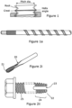
- a thread comprise a continuous helical ridge formed on the inside (nut) or outside (screw) of a cylinder. With reference to Figure 1 , this ridge is called the crest. Between each crest is a space, called the root. Threads are set at an angle to the axis of the bolt or nut. This slope is called the helix angle, which is typically in the range 10° - 80°. The angle must be sloped, either upward to the right (for right-hand threaded screws) or upward to the left (for left-hand threaded screws). The thread forms a "V" shape at the root between crests. The angle of this "V” is called the thread angle, and is determined by fastener engineers. Most screw threads used on machines for fastening components say, for example on a bicycle, use a 60-degree thread angle.
- a general distinction between a screw and a bolt is that a bolt enters a substrate from a first side, passes through the substrate and takes a nut on an opposite side, whereas a screw takes no nut because it threads directly into the substrate i.e. a bolt bolts several things together whilst a screw screws into something.
- a screwbolt is a single fixing for the majority of construction materials that is typically easy to install and has high pull out and shear values.
- Helix angles of a typical screwbolt are generally of the order of 25° - 80°, although more often in the range 45° - 70°, whilst the helix angle of a standard machine bolt is of the order 25° or less.
- a tap In order to create a thread on an inside surface of a nut or other apertured material substrate, it is common to employ a tap, as is shown in Figure 2 .
- the hole size In use, a tap is rotated as it cuts into and removes a certain amount of material, leaving an internal thread.
- the tap drill size In use, engineers have found that if the size of hole corresponds with the tap size, then the hole would be considered as being too small, the tap will have difficulty removing material, and a great deal of force in turning the tap will be required.
- the tap will tend to bind in the hole, with no room for the cut material to disperse - which is why taps tend to have three or more cutting lands with spaces therebetween.
- the tap 20 has five lands 21. If the hole is too large, the tap will cut with little problem, but the internal thread will not be the correct size for the bolt/screw, and failure during tightening or use is very likely.
- a thread swaging bolt per US3492908 is shown, where the bolt has a tapered distal end 22 provided with flutes 23, the flutes extending into an adjacent portion of major diameter of the bolt, whereby to define a tap-thread section 24.
- the proximal end of the bolt is provided with a thread 25 of said major diameter in correspondence with the tap.
- the tap-thread section 23 operably defines a corresponding screwthread, to enable fastening and subsequent unfastening of the bolt and similar threaded bolts.
- Tension in the fastener depends largely upon the amount of torque applied in tightening of the fastener and the size of the thread. Generally, engineers will specify a thread size large enough to handle the anticipated stresses. The amount of pressure applied by a thread can be substantial in order to hold an associated joint secure. Whilst a common cause for threaded fasteners loosening is simply a lack of tension applied during initial assembly, generally speaking vibration, stress, use, or abuse cannot typically overcome the amount of clamping force in a properly sized and secured threaded fastener. As a simple rule of thumb, any fastener should be tightened as tight as possible without failure of the thread or the component parts. This means the weakest part of the joint determines the limits of tension, and hence, torque.
- an M8 bolt having a pitch of 1.25 when manufactured to British Standard BS3692 will have a proof load of 21.2KN and withstand a torque of 22.8Nm whilst an M30 bolt will have corresponding values of 336KN and withstand a torque of 1356Nm.
- Proof load represents the usable strength range and is the maximum stress (load tension) that a metal can resist without permanently deforming (as in elongating).
- Technical data in respect of nut and bolt combinations can be obtained from suppliers of bolts such as Pockside Export Limited, for example.
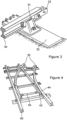
- FIG. 3 An example shall now be considered with reference to Figure 3 , where there is shown an end portion of a rail (track) 30 for a railway, the rail being positioned upon a chair 31 which, in turn, rests upon a sleeper 32, which is set in ballast.
- fishplates are employed to connect the ends of adjacent track length so as to provide an effective continuous length of track.
- a fishplate 33 is shown with a fishbolt extending therethrough.
- railway junction (points) or railroad switch being a mechanical installation enabling railway trains to be guided from one track to another, such as at a railway junction, where a spur track or siding track 30 branches off a main line 40.
- the junction consists of a pair of linked tapering rails, known as points 43 (also referred to as switch rails or point blades), lying between the diverging outer rails 44 (the stock rails). These points can be moved laterally into one of two positions at a switch point 45, the switch rails being connected by a tie bar 45 to ensure that each switch rail of a pair is positioned correctly.
- the present invention seeks to provide an improved screwbolt system for use in engineering and construction.
- the present invention also seeks to provide a screwbolt for use as a fastener in harsh conditions of load and have a reduced tendency to unfasten.
- the present invention also seeks to provide a method of installing such screwbolts.
- a screwthreaded fastening arrangement per claim 1. It has been found that the application of torque in rotating a first metallic fastening component of a first hardness relative to a second metallic fastening of a second hardness must be maintained to ensure that the frictional forces induce frictional welding between the surfaces such that upon ceasing relative movement, the first and second parts become welded with respect to their mutual engaging contact surfaces.
- the shank component is provided with the helix and has the greater surface hardening
- the inside diameter of the nut component is conveniently in the range of 100% - 110% the diameter of the shank, with the diameter of the thread necessarily being greater than the inside diameter of the nut component and the diameter of the shank portion.
- the thread is raised from a working surface in the range of 0.5 - 10% of the diameter when arranged upon the shank or an inside surface of the nut component.
- the length of the nut comprises at least at least one turn of the helix thread, preferably at least one and a half turns and further preferably at least two turns of the helix thread.
- the helix angle is the angle of a screw flight (leading edge of the land of a screwthread) relative to a plane containing the screwthread axis.
- the helix may be cut either right hand or left hand, although the helix angle is not commonly altered from what is typically a standard square pitch, such a change can have a significant impact on processing.
- Traditionally it has been believed that a maximum efficiency of a screwthread can be achieved when the helix angle lies between 40° and 45°, although a reasonable efficiency can be achieved above 15°.
- the helix angle is useful in determining the amount of torque to be applied in power screw applications, although the present invention differs in that the actions of the screwthread are not merely to pass through previously created thread, but can also enable an initial engagement of the formed screwthread.
- the hardness of the inside surface of the nut component is conveniently in the range of 10 - 200 HB and the hardness of the threaded helix being in the range 200 - 1000HB or more when the nut component is received in a substantially blank form.
- the hardness of the threaded helix when comprising part of an inside surface of the nut component is conveniently in the range of 200 - 1000HB and the hardness of the shank in which it defines a fastening thread is conveniently in the range 10 - 200 HB, whereby the harder surface can engage with the less hard surface material.
- the component having the screwthread is the generally circularly cylindrical shank component.
- the nut component can comprise a simple tubular item with at least two flat surfaces (flats) upon an external surface defined parallel to an axis of the tubular item.
- the flats are preferably heat treated or otherwise to improve their hardness.
- the nuts are provided with a lead-in taper. It has been found that the taper can assist in the starting of a thread and, inter alia, assist in maintaining the two parts in a correct coaxial orientation.
- the lead-in section of the nut is provided with a lead-in threaded section.
- the screwthread can comprise a pair of parallel spaced apart helical ridges, in tests, it has been shown that parallel spaced apart threads more readily provide a vibration-proof fixing, it is believed that this is due to the simplicity of the frictional welding process involved. Heat generated by the frictional welding process is generated at the contact areas - direct heat input occurs at the weld interfaces and is confined in a small volume.
- threads can be provided, for example, a triple thread; optionally with first and third threads being of a reduced height, although the heat generated during rotation is spread over a wider volume, meaning that greater rotational speeds need to be achieved, with an ensuing benefit that, per unit length of, a greater degree of heating is achieved, complementing the cold welding process, inter alia assisting by reducing friction, to a degree, noting that anti-friction coatings can be employed, especially where it is not desired that a nut to attach to a portion of shank.
- the component provided with the formed threaded section is the nut; this has the advantage that only nuts need to be heat treated and tapped, as opposed to the shank item. In such a case, the inside diameter of the threaded section must be less than the diameter of the shank component.
- Rebar short for reinforcing bar
- the nut having a hardened screwthread cutting section could be defined within a part of a structure; a simply formed re-bar or similar could be introduced into the nut section; further components could be attached to the arrangement by means of further, separate nut components.
- an improved vibration-proof fastening can be provided by the use of a screwbolt in conjunction with a fastening means comprising a simply apertured member - i.e. without any internal thread - with a relatively low hardness, in common with that of a mild steel, for example.
- a screwbolt in conjunction with a fastening means comprising a simply apertured member - i.e. without any internal thread - with a relatively low hardness, in common with that of a mild steel, for example.
- the Brinell hardness (HB) of a heat-treated screwbolt can be of the order of 200 - 1000 HB (or more)
- the Brinell hardness of mild steel is 120 HB. Given the relative positions of the types of steel, significant Galvanic issues will not arise. Notwithstanding this, other materials could be used, which may prove more economically viable in certain instances.
- the hardness of hardened AW-6060 Aluminium is 75 HB and 18-8 (304) annealed stainless steel is 200 HB.
- the hardness of untreated (pure) metals such as aluminium and copper respectively have hardness values of 15 HB and 35 HB.
- a galling occurrence about a threaded section may not be required - for example the threaded section is too long, in which case, a lubricious coating of the substrate engagement thread can be applied.
- a dry film lubricant such as one of a fluoropolymer coating; a fluoropolymer coating within a polymer matrix and a molybdenum disulphide coating could be applied, which agents are readily available.
- the dry film coating can be applied directly to the anchor bolt.
- the dry film coating can be applied upon one or more base coats, which base coats are applied to the anchorbolt.
- the lubricious coating can have a thickness in the range of 1 - 25 microns. Conveniently, the dry film lubricant has a friction coefficient from 0.2 - 0.01.
- the screwbolt can be removed by the use of a suitable tool with respect to the drive head portion, which is conveniently of a hexagonal or square cross-section.
- a suitable tool with respect to the drive head portion, which is conveniently of a hexagonal or square cross-section.
- the component with the greater hardness can be re-used several times, although the re-use of an internally threaded fastening means is not recommended given that the thread formed upon initial use will be complementary to a screwbolt of first use. Notwithstanding this, the harder material component should be inspected to ensure that damage has not occurred to its integrity.
- axial forces tensile loads
- the present invention has applications across a range of construction sectors outside the rail industry, including repair work, especially in communication networks such as vehicular highways and tunnelling.
- repair work especially in communication networks such as vehicular highways and tunnelling.
- the present invention can provide a secure substrate anchoring can provide an increased efficiency and improved costs on many major engineering and construction products around the world.
- a fastener comprising a metallic screwbolt 50 comprising a shank 51 with a twin helix screwthread 52 defined thereon, a flanged head 53 and a metallic securement nut 54, which screwbolt in the form of the blank is of a right circular cylindrical form.
- the screwthread 52 comprises a ridge-groove-ridge twin helix configuration that extends helically along the shank 51 and comprises a pair of parallel opposed ridges 55 upstanding from an adjacent land 56, with a groove 57 defined therebetween.
- Two substrates 58 are fastened together - with washers 59 at either side thereof.
- the ridges of the screwthread 52 of the shank member are hardened and which ridges extend typically in the range of 0.5 - 3 mm, more typically in the range 0.8 - 1.6mm above the diameter of the shank, which for this M10 bolt would be situated between the screwbolt head and the securement nut (ideally employing one or more washers to, inter alia, spread the load when securely abutting to opposite sides of the connected substrates).
- the threaded shank member is an M10 bolt, meaning that the diameter of the shank is 9.7 - 9.9mm - i.e.
- the screw pitch being of the order of twice the diameter
- the major diameter of the helices being in the range of 10 - 15% of the diameter of the shank and the spacing between the helices is of the order of 4 - 6mm, with a well-depth of 1-2mm, being approximately 105 of the diameter of the shank.
- the internal diameter of the nut is 10.5mm meaning that the hardened ridges will cut into the softer material of the inside surface of the nut.
- the lead-in thread at the distal end of the bolt must be sharp.
- the outer surface of the nut can be heat treated whereby to enable purchase by wrenches and the like without significant rounding.
- Washers 59 are often used with threaded fastener. The use of a washer distributes stresses that arise around a bolted joint. Additionally, the washer reduces friction as the bolt turns. Generally, it is best to have at least one washer under the turning part of the fastener, either the nut or the head. These bolts are commonly available in shank diameter sizes of 6, 8, 10, 12, 16 & 20mm, but other sizes can be made for particular applications.
- the components are substantially affixed to one another by means of friction welding where large turning forces applied with respect to one component relative to the other component cause significant pressures of the parts to act mutually against each other raising temperature. It is believed that by reason of such heat being generated at the weld interface a small heataffected zone is created, which in turn leads to a fast joining time (of the order of a few seconds) noting that in the process of tightening one component with respect to another, the movement must be continuous and, it has been found that electrically powered / compressed air power tools (e.g.
- Friction welding techniques benefit from the welds generally being melt-free, which mitigates grain growth in engineered materials, such as high-strength heat-treated steels, as is the case with the hardened thread helices. Another advantage is that the motion tends to "clean" the surface between the materials being welded, which means they can be joined with less preparation, with the debris being removed from contact surfaces.
- a fastener comprising a screwbolt 50 having a shank 51 with a screwthread 52 defined thereon, a flanged head 53 and a securement nut 54, which screwbolt in the form of the blank is of a right circular cylindrical form.
- the threaded shank member is an M10 bolt
- the securement nut comprises a simple body having two flats defined thereon for engagement with a wrench.
- the fastening nut 54 Following attachment, applying a suitable degree of torque, taking into account size of fastener and relative hardness of the components, the fastening nut 54 became fixed in position due, it is believed at least in part, to a friction welding action and, where the hardness of one material permits, to a degree of galling.
- the axial dimension of the land 56 is at least 50% of the blank diameter with the result that relatively large amounts of substrate material are disposed between the ridge-groove-ridge configuration when the fixing device is in place.
- the nut - having two flats 59 has an internal diameter in of 9.7mm. Prior to attachment, the nut has no particular thread design defined on an inside surface thereof; conveniently, it can be uniformly circularly cylindrical.
- the material surrounding the hole defined within the nut has a hardness in the range of 1 - 200 HB, compared to a hardness of the thread being typically 200 - 1000HB.
- HAB Hexagon Screwbolt
- the properties of a 12 mm ISO grade 10.9 material was provided with a torque limit of 112.7Nm.
- the steel employed for the bolt was Boron Steel BS3111/9/2.1.A, having a mechanical zinc finish, being case hardened and having a Brinell hardness of 200, not including the helices which are hardened within the range 600 - 1000. It will be apparent that the invention can be applied to a wide variety of metallic fastening materials.
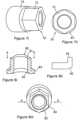
- Figures 7i and 7ii show a second type of nut 70 to be employed with a screwbolt;
- the nut comprises a first hexagonal section 71, whereby standard wrenches, ratchet drivers and the like permit engagement with the nut 70.
- the second section comprises a circularly cylindrical element 72, which when rotated and supported by hand can be more easily handled, whereby to assist in control during a fastening process.
- the increased axial length provides a distance sufficient to enable a sufficient portion of thread to engage with a screwbolt, noting that a screwbolt pitch can be 2cm or greater and the axial length of the nut must be at least equivalent to a pitch of the thread; preferably one and half times the pitch of the thread and more preferably twice the pitch.
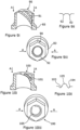
- Figures 8i shows a first alternative style of nut 80 in perspective sectional view wherein the tubular inside bore 81 of the nut has a lead-in /chamfered section 82, the view being a section on A - A per Figure 8iii , which shows the nut from an off-axis perspective view, with a regular six-sided hexagonal head 84 having a flared section 83 operable to spread forces onto a part to be fastened when in use.
- Figure 8ii shows the profile of an inside wall section of the bolt 80, indicating the lead in 82 relative to an otherwise plain bore 81.
- the nuts are "soft" to allow the screwbolt with which the nut will cooperate with to cut its own thread.
- Figure 9i shows a second alternative style of nut 90 in perspective view wherein the tubular inside 91 of the nut has no lead-in section, but instead has a lead-in thread section comprising two grooves 92, 93 the perspective view being a section on A - A per Figure 9iii , again in an off-axis perspective view, which shows the nut, with a regular six-sided hexagonal head having a flared section 83 operable to spread forces onto a part to be fastened when in use.
- Figure 9ii shows the profile of an inside wall section of the bolt 90, indicating the lead in screwthread 92, 93 relative to an otherwise plain bore 91.
- Figure 10i shows a second alternative style of nut 100 in perspective view wherein the tubular inside 101 of the nut has an alternative lead-in thread section comprising two female channels 103, 104 having a male helix 105 therebetween, the perspective view being a section on A - A per Figure 10iii , again in an off-axis perspective view, with the nut being a regular six-sided hexagonal head.
- Figure 10ii shows the profile of an inside wall section 101 of the bolt 100, indicating the lead in screwthread 103, 105, 104 as described above. This enhanced screwthread lead-in is believed to enable a torque load to be accepted without stripping and thereby facilitate use with screwbolts as shown in figures 6i, 6ii above.
- Screwbolts as made by the Applicant Company are made of hardened steel; in particular, the helices are hardened beyond the standard Brinell hardness of approx. 200 up to 1000, preferably 600 - 1000, more preferably 700 - 900, to enable the screwbolts to have a self-cutting capability when used in, for example, a concrete bore, dimensioned to enable passage thereof upon driving by the use of a wrench or power tool driving the head or stud in the case of a stud-bolt which may have a drive head that has engagement features which do not extend beyond the diameter of the shank, two distinct types of thread may be applied upon the shank for engagement with distinct coupling nuts, as indicated in Figure 1a .
- Modern and traditional construction fastening bolts are made from a variety of steels which are manufactured to increase strength.
- Conveniently, extreme endurance fastening bolts are manufactured with boron steel, which are cold forged, thread rolled and then subjected to a heat treatment and yellow passivation. Tempering, following oil or water quenching after forming, toughens boron steels.
- the addition of only 0.001-0.003% soluble boron to a suitably protected base steel can produce an increased hardenability compared to that obtained by additions of about 0.5% manganese, chromium or molybdenum, but with little effect on the as-rolled, normalised or annealed strength.
- An improved vibration-proof fastening in accordance with the invention can be provided by the use of a screwbolt in conjunction with a fastening means comprising a simply apertured member - i.e. without any internal thread - with a relatively low hardness, in common with that of a mild steel, for example.
- the nut may be provided with a hardened inside face for forming a die, which material, with a hardness of 800-1000 HB can then work around a untreated steel rod, such as re-bar, conveniently made of a general uniform cross section, having a hardness of 120HB. Whilst specific values have been provided, it will be appreciated that a wide variation of values can be used in practice.
- HB Brinell hardness
- AW-6060 Aluminium 75 HB 18-8 (304) annealed stainless steel is 200 HB.
- Untreated / unalloyed (pure) metals such as Aluminium and Copper have hardness values of 15 HB and 35 HB.
- a distal, entry end of the shank element is of a reduced diameter and is configured so as to provide a self-tapping capability, when the shank supports a threaded ridge element, the height of the ridges can be conveniently increased from zero to full height over the first full turn.
- the fixing device is introduced into an apertured bore in a substrate such as a fishplate by turning so as to form a thread on the interior walls of the bore.
- the helix angle of the helical threads will be in a range from 20° to 80°.
- the shank component of the screwthreaded fastening of the invention has threads which have a helix angle of from 30° to 75°.
- the physical dimensions as between parts can also be permitted to vary; for example, the inside diameter of a nut component need not correspond generally to a shank diameter, but the helix diameter will matter more, with regard to an ease of fastening and to the ultimate loads that can be applied.
- a lubricious coating to assist the two components to initially move - given that the benefit of such coatings diminish under heat. Nonetheless, inventors have determined that a range of dry film lubricants can be selected; preferred dry film lubricants can have provide resistance to abrasion prior to cutting the thread in the desired fastened position. Friction results from two surfaces sliding across each other and friction is quantified as a dimensionless number that describes the reduction of drag (force) between the sliding parts, whereas release is the property of a surface which results in an inability of substances to adhere to it and is a function of surface energy.
- the screwbolt can be formed by thread rolling with a helical bore wall engagement configuration by a thread rolling apparatus, as is known.
- a thread-rolling station comprises a fixed die and a displaceable die; the two dies are spaced apart by a gap therebetween being equal to the core diameter of the product being rolled.
- the displaceable die is displaceable in reciprocating fashion.
- a blank is inserted between the fixed and moving dies by manual or mechanical means as is known in the thread-rolling art.
- the reciprocating action of the moving dye then carries the blank between them, during this time, the blank is plastically deformed to the face of the dyes as the blank rolls along the faces thereof. This gives rise to formation of the helical bore engagement configuration: die grooves give rise to ridges in the anchorbolt and die ridges give rise to grooves in the anchorbolt.
- galling Whilst it is believed that for steel-steel metallic components, friction welds will result as a primary fastening force, galling will also occur to a degree. Galling is most commonly found in metal surfaces that are in sliding contact with each other. It is especially common where there is inadequate lubrication between the surfaces. However, certain metals will generally be more prone to galling, due to the atomic structure of their crystals. For example, aluminium is a metal that will gall very easily, whereas annealed (softened) steel is slightly more resistant to galling and fully hardened steel is very resistant to galling.
- the inventive concept of the present invention can have far reaching consequences; by friction welding similar and dissimilar metals together further benefits can be realised.
- the vibration proof aspect is substantial for many applications.
- the joints can be fully electrically conductive with respect to each other.
Landscapes
- Engineering & Computer Science (AREA)
- General Engineering & Computer Science (AREA)
- Mechanical Engineering (AREA)
- Physics & Mathematics (AREA)
- Geometry (AREA)
- Dowels (AREA)
- Mutual Connection Of Rods And Tubes (AREA)
Claims (11)
- Schraubengewinde-Befestigungsanordnung, wobei die Anordnung eine im Allgemeinen kreiszylindrische Schaftkomponente (50), die eine erste Oberflächenhärte aufweist, und eine Mutterkomponente (54), die eine im Allgemeinen kreiszylindrische Öffnung mit einer Innenfläche mit einer zweiten Härte aufweist, umfasst, wobei ein Außendurchmesser des Schafts einem Innendurchmesser der Mutterkomponente entspricht; wobei die Schaftkomponente mit einem Schraubengewinde (52), das einen Schrägungswinkel im Bereich von 30° - 75° aufweist, versehen ist, das Schraubengewinde eine Oberflächenhärte hat, die größer als die Oberflächenhärte der Mutterkomponente ist, das Schraubengewinde sich in Bezug auf die Stegfläche (56) der Schaftkomponente nach außen um eine durchgehende Schraubenlinie (55) erstreckt; wobei das Schraubengewinde imstande ist, mit der Oberfläche der Mutterkomponente in Eingriff zu kommen und wobei es bei einer relativen Rotationsbewegung und einer axialen Vorwärtsbewegung zwischen diesen imstande ist, ein entsprechendes Gewinde darin zu schneiden; dadurch gekennzeichnet, dass das Schraubengewinde eines von einem Paar paralleler, voneinander beabstandeter, wendelförmiger Rippen oder von drei parallelen, voneinander beabstandeten, wendelförmigen Rippen umfasst, und dass während der Anwendung bei Beendigung der Rotationsvorwärtsbewegung ein Befestigungszustand durch Verschweißen zwischen dem Schraubengewinde und dem entsprechend geschnittenen Gewinde herbeigeführt wird, wodurch eine Loslösung durch Vibration verhindert wird.
- Schraubengewinde-Befestigungsanordnung nach Anspruch 1, wobei der Innendurchmesser der Mutterkomponente (54) im Bereich zwischen 110 % - 100 % des Durchmessers des Schafts (56) liegt und der Durchmesser des Gewindes größer als der Innendurchmesser der Mutterkomponente ist.
- Schraubengewinde-Befestigungsanordnung nach Anspruch 1 oder 2, wobei das Gewinde von einer Arbeitsfläche (56) im Bereich von 0,5 - 10 % des Durchmessers des Schaftstegs abgehoben ist.
- Schraubengewinde-Befestigungsanordnung nach einem der Ansprüche 1 - 3, wobei die Länge der Mutter (54) mindestens eine Windung des Spiralgewindes umfasst.
- Schraubengewinde-Befestigungsanordnung nach einem der Ansprüche 1 - 3, wobei die Länge der Mutter (54) mindestens zwei Windungen des Spiralgewindes umfasst.
- Schraubengewinde-Befestigungsanordnung nach einem der Ansprüche 1 - 5, wobei die Länge der Mutter (54) im Wesentlichen glatt ist, jedoch einen mit Gewinde versehenen Gewinde-Einführabschnitt umfasst, der mindestens eine Viertelwindung des Spiralgewindes umfasst.
- Schraubengewinde-Befestigungsanordnung nach einem der Ansprüche 1 - 5, wobei die Innenwand der Mutter (54) im Wesentlichen parallel ist, jedoch einen Einführabschnitt umfasst, der mindestens eine Viertelwindung des Spiralgewindes umfasst.
- Schraubengewinde-Befestigungsanordnung nach einem der Ansprüche 1 - 7, wobei die Härte der Innenfläche der Mutterkomponente (54) im Bereich von 10 - 200 HB und die Härte der Gewindespirale im Bereich von 200 - 1000 HB liegt, wenn die Mutterkomponente in einer im Wesentlichen blanken Ausformung aufgenommen wird.
- Schraubengewinde-Befestigungsanordnung nach einem der Ansprüche 1 - 8, wobei die Mutterkomponente (54) ein einfaches rohrförmiges Element mit mindestens zwei flachen Oberflächen (Abflachungen) auf einer Außenfläche, die parallel zu einer Achse des rohrförmigen Elements definiert ist, umfasst.
- Schraubengewinde-Befestigungsanordnung nach Anspruch 9, wobei vier oder sechs Abflachungen jeweils in einer im Allgemeinen quadratischen bzw. regelmäßigen sechseckigen Anordnung ausgestaltet sind.
- Verfahren zum Bereitstellen einer Schraubengewinde-Befestigung zwischen einer im Allgemeinen kreiszylindrischen Schaftkomponente (51), die eine erste Oberflächenhärte aufweist, und einer Mutterkomponente (54), die eine Innenfläche mit einer zweiten Härte aufweist,wobei ein Außendurchmesser des Schafts einem Innendurchmesser der Mutterkomponente entspricht;wobei die Schaftkomponente die größere Oberflächenhärte aufweist und mit einem Schraubengewinde (52) versehen ist, das einen Schrägungswinkel im Bereich von 30° - 75° aufweist, wobei sich das Schraubengewinde in Bezug auf die Stegfläche der Schaftkomponente nach außen um eine durchgehende Schraubenlinie erstreckt, wobei das Schraubengewinde eines von einem Paar paralleler, voneinander beabstandeter, wendelförmiger Rippen oder von drei parallelen, voneinander beabstandeten, wendelförmigen Rippen umfasst;wobei das Verfahren die folgenden Schritte umfasst:Eingreifen des Schraubengewindes in die Innenfläche der Mutterkomponente;Schneiden eines entsprechenden Gewindes in die Innenfläche der Mutterkomponente nach einer relativen Rotationsvorwärtsbewegung desselben; Erzeugen von Hitze an Bereichen des Gewindekontakts; wobei nach Beendigung einer solchen Rotationsvorwärtsbewegung eine Abkühlung und Fixierung der Verbindung durch Schweißen ermöglicht wird, wodurch eine gegen Loslösung durch Vibration widerstandsfähige Fixierung bereitgestellt wird.
Applications Claiming Priority (3)
| Application Number | Priority Date | Filing Date | Title |
|---|---|---|---|
| GBGB1618301.4A GB201618301D0 (en) | 2016-10-28 | 2016-10-28 | Improvements in or relating to screwbolts |
| GBGB1705538.5A GB201705538D0 (en) | 2016-10-28 | 2017-04-05 | Improvements in or relating to screwbolts |
| PCT/GB2017/000159 WO2018078311A1 (en) | 2016-10-28 | 2017-10-30 | Improvements in or relating to screwbolts |
Publications (3)
| Publication Number | Publication Date |
|---|---|
| EP3532739A1 EP3532739A1 (de) | 2019-09-04 |
| EP3532739C0 EP3532739C0 (de) | 2024-01-17 |
| EP3532739B1 true EP3532739B1 (de) | 2024-01-17 |
Family
ID=57963664
Family Applications (1)
| Application Number | Title | Priority Date | Filing Date |
|---|---|---|---|
| EP17811671.1A Active EP3532739B1 (de) | 2016-10-28 | 2017-10-30 | Verbesserungen an oder im zusammenhang mit schraubenbolzen |
Country Status (4)
| Country | Link |
|---|---|
| US (1) | US20200032832A1 (de) |
| EP (1) | EP3532739B1 (de) |
| GB (4) | GB201618301D0 (de) |
| WO (1) | WO2018078311A1 (de) |
Families Citing this family (3)
| Publication number | Priority date | Publication date | Assignee | Title |
|---|---|---|---|---|
| DE102020108589A1 (de) * | 2019-08-08 | 2021-02-11 | Ludwig Hettich Holding Gmbh & Co. Kg | System zum Befestigen eines Ankers in einem mineralischen Untergrund |
| CN113297711B (zh) * | 2021-07-28 | 2022-01-07 | 广东电网有限责任公司中山供电局 | 一种无源松动预警螺栓的结构优化方法及装置 |
| CN115899048B (zh) * | 2022-11-04 | 2024-05-31 | 中国电子科技集团公司第十研究所 | 一种空间站防漂移螺杆组件 |
Family Cites Families (31)
| Publication number | Priority date | Publication date | Assignee | Title |
|---|---|---|---|---|
| NL15093C (de) | 1924-01-30 | |||
| US2167558A (en) * | 1937-06-24 | 1939-07-25 | Lamson & Sessions Co | Self-tapping bolt |
| US3234986A (en) * | 1963-10-24 | 1966-02-15 | Besly Welles Corp | Means for threadedly joining two members |
| US3314326A (en) * | 1964-10-20 | 1967-04-18 | Republic Ind Corp | Self-threading nut with interrupted threads |
| US3364807A (en) * | 1965-11-26 | 1968-01-23 | Tinnerman Products Inc | Threadless nut type fastener |
| US3491646A (en) * | 1967-05-22 | 1970-01-27 | George A Tinnerman | Fastening means for a rotational fastener and method |
| US3501995A (en) * | 1968-12-02 | 1970-03-24 | Illinois Tool Works | Thread-cutting nut |
| US3492908A (en) | 1969-01-17 | 1970-02-03 | Microdot Inc | Thread swaging screw or bolt |
| US4347636A (en) * | 1979-11-07 | 1982-09-07 | Lamson & Sessions Co. | Nut and method of forming the same |
| US4576534A (en) * | 1983-08-04 | 1986-03-18 | Illinois Tool Works Inc. | Thread form for soft material |
| US4842437A (en) * | 1987-11-16 | 1989-06-27 | Ryder International Corporation | Thread forming nut with locking portion |
| US4934859A (en) * | 1988-11-03 | 1990-06-19 | Textron Inc. | Locking nut with multiple thread forming leads |
| US5000639A (en) * | 1989-01-24 | 1991-03-19 | Paul B. Elswick | Self-threading bolt |
| US4889453A (en) * | 1989-02-28 | 1989-12-26 | Hubbell Incorporated | Method of forming a tapped hole |
| GB2290593A (en) * | 1994-06-16 | 1996-01-03 | Timothy Mark Jeffery | Nuts adaptable to different sizes and threads of shanks |
| DE29614832U1 (de) * | 1996-08-26 | 1997-01-02 | Trw Occupant Restraint Systems Gmbh, 73551 Alfdorf | Befestigungsmittel bei einem Fahrzeuginsassen-Rückhaltesystem |
| GB9715779D0 (en) * | 1997-07-26 | 1997-10-01 | Unifix Ltd | Improved fixing anchor |
| US5909990A (en) * | 1998-07-16 | 1999-06-08 | Gombos; Joseph | Threadless nut |
| US6035495A (en) * | 1998-08-11 | 2000-03-14 | Builder's Best, Inc. | Hose clamp |
| DE19944589A1 (de) * | 1999-09-16 | 2001-03-22 | Ejot Verbindungstech Gmbh & Co | Schraubverbindung |
| US6817816B2 (en) * | 2002-08-13 | 2004-11-16 | Nd Industries, Inc. | Tapping assist fastening element and method |
| US20070243043A1 (en) * | 2006-04-17 | 2007-10-18 | Acument Intellectual Properties, Llc | High performance thread forming screw |
| US20090220296A1 (en) * | 2008-02-28 | 2009-09-03 | Bowling Jr Edwin D | Partially threaded bolt for use with a self-threading fastener and method of use |
| JP4787295B2 (ja) * | 2008-07-14 | 2011-10-05 | 株式会社トープラ | 高強度セルフフォーミングねじによるねじ締結構造体 |
| US8465240B2 (en) * | 2009-01-06 | 2013-06-18 | Alcoa Inc. | Advanced nut and bolt |
| US8529178B2 (en) * | 2010-02-19 | 2013-09-10 | Nucor Corporation | Weldless building structures |
| DE102010043589A1 (de) * | 2010-11-08 | 2012-05-10 | Baier & Michels Gmbh & Co. Kg | Gewindeerzeugende Mutter, Rohteil zur Herstellung der Mutter und Schraubverbindung aus Mutter und Bolzen |
| WO2013094672A1 (ja) * | 2011-12-22 | 2013-06-27 | 株式会社ヤマザキアクティブ | 締結部材 |
| DE102012009400B4 (de) * | 2012-05-10 | 2014-02-13 | Sfs Intec Holding Ag | Bohrschraube und deren verwendung |
| EP2944834B1 (de) * | 2014-05-14 | 2019-03-27 | Volvo Car Corporation | Befestigungsanordnung |
| US20160186795A1 (en) * | 2014-12-15 | 2016-06-30 | Mid-State Bolt and Nut Co., Inc. | Threaded screw with shank slot |
-
2016
- 2016-10-28 GB GBGB1618301.4A patent/GB201618301D0/en not_active Ceased
-
2017
- 2017-04-05 GB GBGB1705538.5A patent/GB201705538D0/en not_active Ceased
- 2017-10-30 EP EP17811671.1A patent/EP3532739B1/de active Active
- 2017-10-30 WO PCT/GB2017/000159 patent/WO2018078311A1/en not_active Ceased
- 2017-10-30 GB GBGB1717872.4A patent/GB201717872D0/en not_active Ceased
- 2017-10-30 GB GB1717874.0A patent/GB2556460B/en active Active
- 2017-10-30 US US16/346,062 patent/US20200032832A1/en not_active Abandoned
Also Published As
| Publication number | Publication date |
|---|---|
| WO2018078311A1 (en) | 2018-05-03 |
| EP3532739A1 (de) | 2019-09-04 |
| US20200032832A1 (en) | 2020-01-30 |
| GB2556460B (en) | 2020-07-01 |
| GB201717872D0 (en) | 2017-12-13 |
| EP3532739C0 (de) | 2024-01-17 |
| GB2556460A (en) | 2018-05-30 |
| GB201705538D0 (en) | 2017-05-17 |
| GB201717874D0 (en) | 2017-12-13 |
| GB201618301D0 (en) | 2016-12-14 |
Similar Documents
| Publication | Publication Date | Title |
|---|---|---|
| CA2711259C (en) | Advanced nut and bolt | |
| US1966835A (en) | Fastening means | |
| US5282707A (en) | Fastening system for locking nut with torque indicating marks | |
| EP3532739B1 (de) | Verbesserungen an oder im zusammenhang mit schraubenbolzen | |
| EP1000249A2 (de) | Mit enger toleranz gewinde aufweisendes befestigungselement | |
| EP3074647B1 (de) | Erweitertes muttern- und schraubensystem | |
| US20130061452A1 (en) | Fastener and method of installing same | |
| US6688988B2 (en) | Looking thread cold forming tool | |
| US20220016750A1 (en) | Torque-angle structural fastening system | |
| US7438513B2 (en) | Ribbed fastener | |
| CA3207528A1 (en) | Torque reducing flow drilling fastener for thick materials and method of using such fastener | |
| CN118391336B (zh) | 一种以结构防松的螺纹副及联结方法 | |
| CA2828676C (en) | Torque-angle structural fastening system | |
| US10655669B2 (en) | Advanced nut and bolt | |
| JP6846828B2 (ja) | 耐破壊用ネジ締結体 | |
| JP7667977B2 (ja) | ブラインドファスナー | |
| Ibrahmi et al. | Experimental study of the effect of the threading process on the mechanical and tribological behaviors of the triangular thread | |
| US1104864A (en) | Rail-joint. | |
| Mack | Joining with Aluminum Alloy Bolts and Nuts | |
| WO2009123579A2 (en) | Space frame connection members | |
| WO2012119764A1 (en) | A high load flanged fastener to be installed by tensioning tools |
Legal Events
| Date | Code | Title | Description |
|---|---|---|---|
| STAA | Information on the status of an ep patent application or granted ep patent |
Free format text: STATUS: UNKNOWN |
|
| STAA | Information on the status of an ep patent application or granted ep patent |
Free format text: STATUS: THE INTERNATIONAL PUBLICATION HAS BEEN MADE |
|
| PUAI | Public reference made under article 153(3) epc to a published international application that has entered the european phase |
Free format text: ORIGINAL CODE: 0009012 |
|
| STAA | Information on the status of an ep patent application or granted ep patent |
Free format text: STATUS: REQUEST FOR EXAMINATION WAS MADE |
|
| 17P | Request for examination filed |
Effective date: 20190527 |
|
| AK | Designated contracting states |
Kind code of ref document: A1 Designated state(s): AL AT BE BG CH CY CZ DE DK EE ES FI FR GB GR HR HU IE IS IT LI LT LU LV MC MK MT NL NO PL PT RO RS SE SI SK SM TR |
|
| AX | Request for extension of the european patent |
Extension state: BA ME |
|
| DAV | Request for validation of the european patent (deleted) | ||
| DAX | Request for extension of the european patent (deleted) | ||
| STAA | Information on the status of an ep patent application or granted ep patent |
Free format text: STATUS: EXAMINATION IS IN PROGRESS |
|
| 17Q | First examination report despatched |
Effective date: 20220330 |
|
| GRAP | Despatch of communication of intention to grant a patent |
Free format text: ORIGINAL CODE: EPIDOSNIGR1 |
|
| STAA | Information on the status of an ep patent application or granted ep patent |
Free format text: STATUS: GRANT OF PATENT IS INTENDED |
|
| INTG | Intention to grant announced |
Effective date: 20230330 |
|
| GRAS | Grant fee paid |
Free format text: ORIGINAL CODE: EPIDOSNIGR3 |
|
| GRAJ | Information related to disapproval of communication of intention to grant by the applicant or resumption of examination proceedings by the epo deleted |
Free format text: ORIGINAL CODE: EPIDOSDIGR1 |
|
| GRAL | Information related to payment of fee for publishing/printing deleted |
Free format text: ORIGINAL CODE: EPIDOSDIGR3 |
|
| STAA | Information on the status of an ep patent application or granted ep patent |
Free format text: STATUS: EXAMINATION IS IN PROGRESS |
|
| INTC | Intention to grant announced (deleted) | ||
| GRAP | Despatch of communication of intention to grant a patent |
Free format text: ORIGINAL CODE: EPIDOSNIGR1 |
|
| STAA | Information on the status of an ep patent application or granted ep patent |
Free format text: STATUS: GRANT OF PATENT IS INTENDED |
|
| INTG | Intention to grant announced |
Effective date: 20230911 |
|
| GRAA | (expected) grant |
Free format text: ORIGINAL CODE: 0009210 |
|
| STAA | Information on the status of an ep patent application or granted ep patent |
Free format text: STATUS: THE PATENT HAS BEEN GRANTED |
|
| AK | Designated contracting states |
Kind code of ref document: B1 Designated state(s): AL AT BE BG CH CY CZ DE DK EE ES FI FR GB GR HR HU IE IS IT LI LT LU LV MC MK MT NL NO PL PT RO RS SE SI SK SM TR |
|
| REG | Reference to a national code |
Ref country code: GB Ref legal event code: FG4D |
|
| REG | Reference to a national code |
Ref country code: CH Ref legal event code: EP |
|
| REG | Reference to a national code |
Ref country code: DE Ref legal event code: R096 Ref document number: 602017078545 Country of ref document: DE |
|
| REG | Reference to a national code |
Ref country code: IE Ref legal event code: FG4D |
|
| U01 | Request for unitary effect filed |
Effective date: 20240214 |
|
| U07 | Unitary effect registered |
Designated state(s): AT BE BG DE DK EE FI FR IT LT LU LV MT NL PT SE SI Effective date: 20240229 |
|
| REG | Reference to a national code |
Ref country code: LT Ref legal event code: MG9D |
|
| PG25 | Lapsed in a contracting state [announced via postgrant information from national office to epo] |
Ref country code: IS Free format text: LAPSE BECAUSE OF FAILURE TO SUBMIT A TRANSLATION OF THE DESCRIPTION OR TO PAY THE FEE WITHIN THE PRESCRIBED TIME-LIMIT Effective date: 20240517 |
|
| PG25 | Lapsed in a contracting state [announced via postgrant information from national office to epo] |
Ref country code: GR Free format text: LAPSE BECAUSE OF FAILURE TO SUBMIT A TRANSLATION OF THE DESCRIPTION OR TO PAY THE FEE WITHIN THE PRESCRIBED TIME-LIMIT Effective date: 20240418 |
|
| PG25 | Lapsed in a contracting state [announced via postgrant information from national office to epo] |
Ref country code: HR Free format text: LAPSE BECAUSE OF FAILURE TO SUBMIT A TRANSLATION OF THE DESCRIPTION OR TO PAY THE FEE WITHIN THE PRESCRIBED TIME-LIMIT Effective date: 20240117 Ref country code: RS Free format text: LAPSE BECAUSE OF FAILURE TO SUBMIT A TRANSLATION OF THE DESCRIPTION OR TO PAY THE FEE WITHIN THE PRESCRIBED TIME-LIMIT Effective date: 20240417 |
|
| PG25 | Lapsed in a contracting state [announced via postgrant information from national office to epo] |
Ref country code: ES Free format text: LAPSE BECAUSE OF FAILURE TO SUBMIT A TRANSLATION OF THE DESCRIPTION OR TO PAY THE FEE WITHIN THE PRESCRIBED TIME-LIMIT Effective date: 20240117 |
|
| PG25 | Lapsed in a contracting state [announced via postgrant information from national office to epo] |
Ref country code: RS Free format text: LAPSE BECAUSE OF FAILURE TO SUBMIT A TRANSLATION OF THE DESCRIPTION OR TO PAY THE FEE WITHIN THE PRESCRIBED TIME-LIMIT Effective date: 20240417 Ref country code: NO Free format text: LAPSE BECAUSE OF FAILURE TO SUBMIT A TRANSLATION OF THE DESCRIPTION OR TO PAY THE FEE WITHIN THE PRESCRIBED TIME-LIMIT Effective date: 20240417 Ref country code: IS Free format text: LAPSE BECAUSE OF FAILURE TO SUBMIT A TRANSLATION OF THE DESCRIPTION OR TO PAY THE FEE WITHIN THE PRESCRIBED TIME-LIMIT Effective date: 20240517 Ref country code: HR Free format text: LAPSE BECAUSE OF FAILURE TO SUBMIT A TRANSLATION OF THE DESCRIPTION OR TO PAY THE FEE WITHIN THE PRESCRIBED TIME-LIMIT Effective date: 20240117 Ref country code: GR Free format text: LAPSE BECAUSE OF FAILURE TO SUBMIT A TRANSLATION OF THE DESCRIPTION OR TO PAY THE FEE WITHIN THE PRESCRIBED TIME-LIMIT Effective date: 20240418 Ref country code: ES Free format text: LAPSE BECAUSE OF FAILURE TO SUBMIT A TRANSLATION OF THE DESCRIPTION OR TO PAY THE FEE WITHIN THE PRESCRIBED TIME-LIMIT Effective date: 20240117 |
|
| PG25 | Lapsed in a contracting state [announced via postgrant information from national office to epo] |
Ref country code: PL Free format text: LAPSE BECAUSE OF FAILURE TO SUBMIT A TRANSLATION OF THE DESCRIPTION OR TO PAY THE FEE WITHIN THE PRESCRIBED TIME-LIMIT Effective date: 20240117 |
|
| PG25 | Lapsed in a contracting state [announced via postgrant information from national office to epo] |
Ref country code: PL Free format text: LAPSE BECAUSE OF FAILURE TO SUBMIT A TRANSLATION OF THE DESCRIPTION OR TO PAY THE FEE WITHIN THE PRESCRIBED TIME-LIMIT Effective date: 20240117 |
|
| PG25 | Lapsed in a contracting state [announced via postgrant information from national office to epo] |
Ref country code: SM Free format text: LAPSE BECAUSE OF FAILURE TO SUBMIT A TRANSLATION OF THE DESCRIPTION OR TO PAY THE FEE WITHIN THE PRESCRIBED TIME-LIMIT Effective date: 20240117 |
|
| REG | Reference to a national code |
Ref country code: DE Ref legal event code: R097 Ref document number: 602017078545 Country of ref document: DE |
|
| PG25 | Lapsed in a contracting state [announced via postgrant information from national office to epo] |
Ref country code: CZ Free format text: LAPSE BECAUSE OF FAILURE TO SUBMIT A TRANSLATION OF THE DESCRIPTION OR TO PAY THE FEE WITHIN THE PRESCRIBED TIME-LIMIT Effective date: 20240117 |
|
| PG25 | Lapsed in a contracting state [announced via postgrant information from national office to epo] |
Ref country code: SK Free format text: LAPSE BECAUSE OF FAILURE TO SUBMIT A TRANSLATION OF THE DESCRIPTION OR TO PAY THE FEE WITHIN THE PRESCRIBED TIME-LIMIT Effective date: 20240117 |
|
| PG25 | Lapsed in a contracting state [announced via postgrant information from national office to epo] |
Ref country code: SM Free format text: LAPSE BECAUSE OF FAILURE TO SUBMIT A TRANSLATION OF THE DESCRIPTION OR TO PAY THE FEE WITHIN THE PRESCRIBED TIME-LIMIT Effective date: 20240117 Ref country code: SK Free format text: LAPSE BECAUSE OF FAILURE TO SUBMIT A TRANSLATION OF THE DESCRIPTION OR TO PAY THE FEE WITHIN THE PRESCRIBED TIME-LIMIT Effective date: 20240117 Ref country code: RO Free format text: LAPSE BECAUSE OF FAILURE TO SUBMIT A TRANSLATION OF THE DESCRIPTION OR TO PAY THE FEE WITHIN THE PRESCRIBED TIME-LIMIT Effective date: 20240117 Ref country code: CZ Free format text: LAPSE BECAUSE OF FAILURE TO SUBMIT A TRANSLATION OF THE DESCRIPTION OR TO PAY THE FEE WITHIN THE PRESCRIBED TIME-LIMIT Effective date: 20240117 |
|
| U20 | Renewal fee for the european patent with unitary effect paid |
Year of fee payment: 8 Effective date: 20241014 |
|
| PLBE | No opposition filed within time limit |
Free format text: ORIGINAL CODE: 0009261 |
|
| STAA | Information on the status of an ep patent application or granted ep patent |
Free format text: STATUS: NO OPPOSITION FILED WITHIN TIME LIMIT |
|
| 26N | No opposition filed |
Effective date: 20241018 |
|
| REG | Reference to a national code |
Ref country code: CH Ref legal event code: PL |
|
| PG25 | Lapsed in a contracting state [announced via postgrant information from national office to epo] |
Ref country code: MC Free format text: LAPSE BECAUSE OF FAILURE TO SUBMIT A TRANSLATION OF THE DESCRIPTION OR TO PAY THE FEE WITHIN THE PRESCRIBED TIME-LIMIT Effective date: 20240117 |
|
| PG25 | Lapsed in a contracting state [announced via postgrant information from national office to epo] |
Ref country code: CH Free format text: LAPSE BECAUSE OF NON-PAYMENT OF DUE FEES Effective date: 20241031 |
|
| PG25 | Lapsed in a contracting state [announced via postgrant information from national office to epo] |
Ref country code: IE Free format text: LAPSE BECAUSE OF NON-PAYMENT OF DUE FEES Effective date: 20241030 |
|
| U20 | Renewal fee for the european patent with unitary effect paid |
Year of fee payment: 9 Effective date: 20251023 |
|
| PGFP | Annual fee paid to national office [announced via postgrant information from national office to epo] |
Ref country code: GB Payment date: 20251023 Year of fee payment: 9 |