EP3532380B1 - Überkopf-lagerbehälter mit einer gelenkanordnung - Google Patents
Überkopf-lagerbehälter mit einer gelenkanordnung Download PDFInfo
- Publication number
- EP3532380B1 EP3532380B1 EP17825949.5A EP17825949A EP3532380B1 EP 3532380 B1 EP3532380 B1 EP 3532380B1 EP 17825949 A EP17825949 A EP 17825949A EP 3532380 B1 EP3532380 B1 EP 3532380B1
- Authority
- EP
- European Patent Office
- Prior art keywords
- wall
- storage bin
- wall panels
- hinge arm
- door
- Prior art date
- Legal status (The legal status is an assumption and is not a legal conclusion. Google has not performed a legal analysis and makes no representation as to the accuracy of the status listed.)
- Active
Links
Images


Classifications
-
- E—FIXED CONSTRUCTIONS
- E05—LOCKS; KEYS; WINDOW OR DOOR FITTINGS; SAFES
- E05D—HINGES OR SUSPENSION DEVICES FOR DOORS, WINDOWS OR WINGS
- E05D3/00—Hinges with pins
- E05D3/06—Hinges with pins with two or more pins
-
- E—FIXED CONSTRUCTIONS
- E05—LOCKS; KEYS; WINDOW OR DOOR FITTINGS; SAFES
- E05D—HINGES OR SUSPENSION DEVICES FOR DOORS, WINDOWS OR WINGS
- E05D15/00—Suspension arrangements for wings
- E05D15/40—Suspension arrangements for wings supported on arms movable in vertical planes
- E05D15/46—Suspension arrangements for wings supported on arms movable in vertical planes with two pairs of pivoted arms
- E05D15/463—Suspension arrangements for wings supported on arms movable in vertical planes with two pairs of pivoted arms specially adapted for overhead wings
-
- B—PERFORMING OPERATIONS; TRANSPORTING
- B64—AIRCRAFT; AVIATION; COSMONAUTICS
- B64D—EQUIPMENT FOR FITTING IN OR TO AIRCRAFT; FLIGHT SUITS; PARACHUTES; ARRANGEMENT OR MOUNTING OF POWER PLANTS OR PROPULSION TRANSMISSIONS IN AIRCRAFT
- B64D11/00—Passenger or crew accommodation; Flight-deck installations not otherwise provided for
- B64D11/003—Stowage devices for passengers' personal luggage
-
- E—FIXED CONSTRUCTIONS
- E05—LOCKS; KEYS; WINDOW OR DOOR FITTINGS; SAFES
- E05D—HINGES OR SUSPENSION DEVICES FOR DOORS, WINDOWS OR WINGS
- E05D5/00—Construction of single parts, e.g. the parts for attachment
- E05D5/02—Parts for attachment, e.g. flaps
-
- E—FIXED CONSTRUCTIONS
- E05—LOCKS; KEYS; WINDOW OR DOOR FITTINGS; SAFES
- E05F—DEVICES FOR MOVING WINGS INTO OPEN OR CLOSED POSITION; CHECKS FOR WINGS; WING FITTINGS NOT OTHERWISE PROVIDED FOR, CONCERNED WITH THE FUNCTIONING OF THE WING
- E05F1/00—Closers or openers for wings, not otherwise provided for in this subclass
- E05F1/08—Closers or openers for wings, not otherwise provided for in this subclass spring-actuated, e.g. for horizontally sliding wings
- E05F1/10—Closers or openers for wings, not otherwise provided for in this subclass spring-actuated, e.g. for horizontally sliding wings for swinging wings, e.g. counterbalance
- E05F1/1091—Closers or openers for wings, not otherwise provided for in this subclass spring-actuated, e.g. for horizontally sliding wings for swinging wings, e.g. counterbalance with a gas spring
-
- E—FIXED CONSTRUCTIONS
- E05—LOCKS; KEYS; WINDOW OR DOOR FITTINGS; SAFES
- E05F—DEVICES FOR MOVING WINGS INTO OPEN OR CLOSED POSITION; CHECKS FOR WINGS; WING FITTINGS NOT OTHERWISE PROVIDED FOR, CONCERNED WITH THE FUNCTIONING OF THE WING
- E05F3/00—Closers or openers with braking devices, e.g. checks; Construction of pneumatic or liquid braking devices
- E05F3/20—Closers or openers with braking devices, e.g. checks; Construction of pneumatic or liquid braking devices in hinges
-
- E—FIXED CONSTRUCTIONS
- E05—LOCKS; KEYS; WINDOW OR DOOR FITTINGS; SAFES
- E05F—DEVICES FOR MOVING WINGS INTO OPEN OR CLOSED POSITION; CHECKS FOR WINGS; WING FITTINGS NOT OTHERWISE PROVIDED FOR, CONCERNED WITH THE FUNCTIONING OF THE WING
- E05F1/00—Closers or openers for wings, not otherwise provided for in this subclass
- E05F1/08—Closers or openers for wings, not otherwise provided for in this subclass spring-actuated, e.g. for horizontally sliding wings
- E05F1/10—Closers or openers for wings, not otherwise provided for in this subclass spring-actuated, e.g. for horizontally sliding wings for swinging wings, e.g. counterbalance
- E05F1/12—Mechanisms in the shape of hinges or pivots, operated by springs
- E05F1/1292—Mechanisms in the shape of hinges or pivots, operated by springs with a gas spring
-
- E—FIXED CONSTRUCTIONS
- E05—LOCKS; KEYS; WINDOW OR DOOR FITTINGS; SAFES
- E05Y—INDEXING SCHEME ASSOCIATED WITH SUBCLASSES E05D AND E05F, RELATING TO CONSTRUCTION ELEMENTS, ELECTRIC CONTROL, POWER SUPPLY, POWER SIGNAL OR TRANSMISSION, USER INTERFACES, MOUNTING OR COUPLING, DETAILS, ACCESSORIES, AUXILIARY OPERATIONS NOT OTHERWISE PROVIDED FOR, APPLICATION THEREOF
- E05Y2201/00—Constructional elements; Accessories therefor
- E05Y2201/20—Brakes; Disengaging means; Holders; Stops; Valves; Accessories therefor
- E05Y2201/21—Brakes
-
- E—FIXED CONSTRUCTIONS
- E05—LOCKS; KEYS; WINDOW OR DOOR FITTINGS; SAFES
- E05Y—INDEXING SCHEME ASSOCIATED WITH SUBCLASSES E05D AND E05F, RELATING TO CONSTRUCTION ELEMENTS, ELECTRIC CONTROL, POWER SUPPLY, POWER SIGNAL OR TRANSMISSION, USER INTERFACES, MOUNTING OR COUPLING, DETAILS, ACCESSORIES, AUXILIARY OPERATIONS NOT OTHERWISE PROVIDED FOR, APPLICATION THEREOF
- E05Y2201/00—Constructional elements; Accessories therefor
- E05Y2201/20—Brakes; Disengaging means; Holders; Stops; Valves; Accessories therefor
- E05Y2201/262—Type of motion, e.g. braking
- E05Y2201/264—Type of motion, e.g. braking linear
-
- E—FIXED CONSTRUCTIONS
- E05—LOCKS; KEYS; WINDOW OR DOOR FITTINGS; SAFES
- E05Y—INDEXING SCHEME ASSOCIATED WITH SUBCLASSES E05D AND E05F, RELATING TO CONSTRUCTION ELEMENTS, ELECTRIC CONTROL, POWER SUPPLY, POWER SIGNAL OR TRANSMISSION, USER INTERFACES, MOUNTING OR COUPLING, DETAILS, ACCESSORIES, AUXILIARY OPERATIONS NOT OTHERWISE PROVIDED FOR, APPLICATION THEREOF
- E05Y2900/00—Application of doors, windows, wings or fittings thereof
- E05Y2900/50—Application of doors, windows, wings or fittings thereof for vehicles
- E05Y2900/502—Application of doors, windows, wings or fittings thereof for vehicles for aircraft or spacecraft
-
- E—FIXED CONSTRUCTIONS
- E05—LOCKS; KEYS; WINDOW OR DOOR FITTINGS; SAFES
- E05Y—INDEXING SCHEME ASSOCIATED WITH SUBCLASSES E05D AND E05F, RELATING TO CONSTRUCTION ELEMENTS, ELECTRIC CONTROL, POWER SUPPLY, POWER SIGNAL OR TRANSMISSION, USER INTERFACES, MOUNTING OR COUPLING, DETAILS, ACCESSORIES, AUXILIARY OPERATIONS NOT OTHERWISE PROVIDED FOR, APPLICATION THEREOF
- E05Y2900/00—Application of doors, windows, wings or fittings thereof
- E05Y2900/50—Application of doors, windows, wings or fittings thereof for vehicles
- E05Y2900/53—Type of wing
- E05Y2900/538—Interior lids
Definitions
- the application relates to an overhead storage bin with a hinge assembly and to a method of connecting a door to a wall of an overhead storage bin.
- Overhead bins in aircraft cabins typically have door hinges which are received within the storage space of the bins, for example attached to an inner surface of the bin walls.
- the hinges accordingly reduce the available storage space within the bin, and accordingly the amount of luggage which can be stored within the bin.
- US 6 398 163 B1 discloses an overhead storage bin with upwardly pivoting hinge/door where the entire hinge assembly is located inside the lateral walls of the storage bin.
- EP 2 865 597 A2 discloses an overhead storage bin for vehicles with upwardly pivoting hinge/door where the hinges of the door are located inside the lateral walls of the storage bin.
- an overhead storage bin comprising the features of claim 1.
- the storage bin can include any one or any combination of the following:
- the wall is a first wall
- the bin body including a second wall opposite the first wall, the second wall having an inner surface within the storage space and an opposed outer surface outside of the storage space, an edge of the second wall including two additional spaced apart wall panels
- the bin further comprising an additional pivot located between the additional wall panels, and an additional hinge arm having a portion located between the additional wall panels and engaged to the additional pivot, the additional hinge arm extending away from the additional wall panels and engaged to the door, the additional hinge arm pivotable about the pivot to be movable within an additional plane aligned with the additional wall.
- the aircraft 1 has a fuselage 2 having a fore end at which a cockpit is located, and an aft end supporting a tail assembly, with the cabin 7 generally located between the cockpit and the tail assembly.
- the tail assembly comprises a vertical stabilizer 3 with a rudder, and horizontal stabilizers 4 with elevators.
- the tail assembly has a fuselage-mounted tail, but other configurations may also be used for the aircraft 1, such as cruciform, T-tail, etc.
- Wings 5 project laterally from the fuselage.
- the aircraft 1 has engines 6 supported by the wings 5, although the engines 6 could also be mounted to the fuselage 2.
- the aircraft 1 is shown as a jet-engine aircraft, but may also be a propeller aircraft.
- the aircraft cabin 7 includes storage bins 10, which are configured as overhead storage bins located over passenger seats 12 in the example shown.
- Each storage bin 10 includes a bin body 14 defining a storage space 16 (for e.g. luggage) and an opening 18 for accessing the storage space 16.
- the storage bin 10 includes a door 20 pivotable between a closed position C where the door 20 closes the opening 18 and an open position O where the door 20 is away from the opening 18 and the opening 18 is accessible. It is understood that the particular configuration shown for the bin 10 is exemplary only and that any other suitable configuration may alternately be used, within the limits defined by the claims.
- the storage bin 10 includes a plurality of walls 22 which have an inner surface 22i ( Figs. 5-6 ) located within the storage space 16 and an opposed outer surface ( Figs. 3-4 and 6 ) located outside of the storage space 16.
- the dimensions of the storage space 16 are thus defined between the inner surface 22i of the walls 22.
- a width W ( Fig. 2 ) of the storage space 16 is defined between the inner surfaces 22i of the opposed side walls 22.
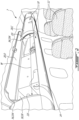
- a hinge assembly 30 in accordance with a particular embodiment of the overhead storage bin is shown.
- the hinge assembly 30 is configured for receiving the door 20 to allow movement of the door 20 between the open and closed positions.
- the wall panels 32, 34 define part of the perimeter of the opening 18 of the storage bin 10.
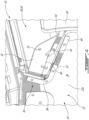
- the wall 22 includes a wall body 36 defining the inner and outer surfaces 22i, 22o.
- a cut-out 38 ( Figs. 4-5 ) is defined along the edge of the wall body 36.
- the inner wall panel 32 is detachably connected to the inner surface 22i of the wall body 36 along the edge of the cut-out 38
- the outer wall panel 34 is detachably connected to the outer surface 22o of the wall body 36 along the edge of the cut-out 38.
- Seals 40 may optionally be provided between the wall panels 32, 34 and the respective surface 22i, 22o of the wall body 36 along their connection. As can be best seen in Fig.
- the wall panels 32, 34 are connected to the wall body 36 by a plurality of fasteners 42 extending through the wall body 36 and the wall panels 32, 34.
- Other suitable types of connections may alternately be used, including detachable connections (i.e. connections which are detachable without causing damage to the wall body 36 and the wall panels 32, 34), and permanent connections (i.e. connections which are not detachable without causing damage to one or both of the wall body 36 and the wall panels 32, 34).
- the two wall panels 32, 34 are also detachably connected to each other, for example through complementary clips or suitable fasteners 33 ( Figs. 4-5 ).
- the wall panels 32, 34 thus extend from the edge of the cut-out 38 to complete the perimeter of the opening 18 of the storage bin 10. Referring to Figs. 3 and 6 , a receiving space 44 is accordingly defined between the wall panels 32, 34, bordered by the cut-out edge of the wall body 36.
- the wall body 36 and wall panels 32, 34 include different materials.
- the wall body 36 includes inner and outer panels 46, made for example of fiberglass composite material, interconnected by a honeycomb core 48, and the wall panels 32, 34 include a plastic material suitable for injection molding. Other configurations and materials are of course possible.
- the wall panels 32, 34 may be defined by an integral part of the wall body 36, for example by a portion of the inner and outer panels 46 extending beyond the core 48.
- the assembly 30 includes a pivot 50 located in the receiving space 44 defined between the wall panels 32, 34.
- the pivot 50 defines a pivot axis 52 intersecting the wall panels 32, 34; the pivot axis 52 extends perpendicularly to the inner and outer wall surfaces 22i, 22o.
- the pivot 50 is connected to both wall panels 32, 34.
- the hinge assembly 30 further includes a hinge arm 54 having a portion located in the receiving space 44 between the wall panels 32, 34 and engaged to the pivot 50.
- the hinge arm 54 has a rigid structure, and is pivotable about the pivot axis 52 to move between the open and closed positions of the door 20.
- the hinge arm 54 extends away from the wall panels 32, 34 for connection to the door 20. Throughout its pivoting motion, the hinge arm 54 remains within a space defined between a plane of the inner surface 22i of the wall 22 and a plane of the outer surface 22o of the wall 22. In other words, the hinge arm 54 pivots in plane P ( Fig. 6 ) which is aligned with the wall 22, i.e.
- a plane P extending between the inner and outer surfaces 22i, 22o of the wall 22 at least in proximity of the opening 18, and in a particular embodiment for the entirety of the wall 22.
- the plane P of movement of the hinge arm 54 is vertical, and the door 20 moves upwardly from the closed position to the open position.
- the hinge arm 54 is connected to the door 20 using any suitable type of connection.
- the hinge arm 54 includes a connection portion extending parallel to the door 20, having a U-shaped cross-section which defines a recess sized to receive an edge of the door 20, and the edge of the door 20 is slidingly engaged in this complementary recess (not shown).
- Other configurations are also possible.
- the outer wall panel 34 defines a stop 56 for abutting the hinge arm 54 when the door 20 is in the open position.
- the cut-out edge of the wall body 36 defines another stop 58 for abutting the hinge arm 54 when the door 20 is in the closed position.
- one or both of the stops 56, 58 may be defined by the inner wall panel 32, or both stops 56, 58 may be defined by the outer wall panel 34.
- a damper 60 is pivotally connected to the hinge arm 54 and to one or both of the wall panels 32, 34, and is located in the receiving space 44 between the wall panels 32, 34.
- the hinge arm 54 is configured so that its connection with the damper 60 and its connection with the pivot 50 are appropriately spaced apart to allow the damper 60 to act on the motion of the hinge arm 54 about the pivot 50.
- the damper 60 biases the door 20 in the open position, i.e. provides sufficient resistance so as to counteract the weight of the door 20 and allow the door 20 to remain in the open position unless a sufficient force toward the closed position is applied to it.
- the damper 60 may have any suitable configuration, including, but not limited to, any suitable type of rate control damper which can control motion through tension and compression. Suitable rate control dampers may be fully mechanical, gas-charged or hydraulic, among other possibilities.
- a similar hinge assembly 30 is provided in the opposite side wall of the bin 10, so that the door 20 is retained by two hinge arms 54, i.e. on hinge arm 54 on each side of the door 20.
- the additional hinge assembly includes wall panels 32, 34, a pivot 50 and a hinge arm 54 similar to that previously described and shown.
- the additional hinge assembly may also include a damper 60; alternately, a single damper may be used to retain the door in the open position.
- FIG. 7 a hinge assembly 130 in accordance with another particular embodiment of the overhead storage bin is shown. Elements similar to that of the embodiment of Figs. 3-6 are identified by a same reference numeral and will not be further described herein.
- the cut-out 138 defined along the edge of the wall body 36 is larger, so that the hinge arm 154 does not come into contact with the wall body 36 at the closed position.
- One or both of the wall panels 32, 34 accordingly define the stop 158 abutting the hinge arm 154 at the closed position.
- the stop 156 abutting the hinge arm 154 at the open position is defined by one or both of the wall panels 32, 34, in proximity of the edge of the cutout 138 in the wall body 36.
- the wall panels 32, 34 are integrally connected to each other, forming part of a monolithic structure.
- the edge of the wall body 36 is accordingly inserted between the two wall panels 32, 34 before connecting the wall panels 32, 34 to the wall body 36, for example using 42 fasteners as shown in Fig. 6 .
- a similar hinge assembly 130 may also be provided in the opposite side wall of the bin 10, as described above.
- the door 20 is accordingly connected to the wall 22 in accordance with the following.
- the receiving space 44 is defined along the edge of the wall forming part of the perimeter of the opening 18 to be closed by the door 20.
- the hinge arm 54, 154 is pivotally connected to the pivot 50 extending within the receiving space 44 so that the hinge arm 54, 154 is pivotable within a plane aligned with the wall 22.
- the door 20 is connected to the hinge arm 54, 154.
- the receiving space 44 is defined by attaching the wall panels 32, 34 to the wall body 36.
- the wall panels 32, 34 may be an integral part of the wall body 36, and the receiving space 44 may be defined for example by removing part of a core extending between the wall panels 32, 34.
- an additional receiving space 44 is defined along the edge of an opposite wall 22, and another hinge arm 54, 154 is pivotally connected to a pivot 50 extending within the additional receiving space 44 so that the other hinge arm 54, 154 is pivotable within a plane aligned with this wall 22.
- the door 20 is connected to both hinge arms 54, 154.
- the hinge assembly 30, 130 advantageously allows for support of the door 20 without causing an obstruction in the storage space 16, since the hinge arm 54, 154 remains outward of the inner wall surface 22i of the corresponding wall 22, and the structure supporting the hinge arm 54, 154 is also provided outward of the inner wall surface 22i.
- the only protrusion of the hinge assembly 30, 130 within the storage space 16 corresponds to the thickness of the inner wall panel 32 where it is attached to the inner surface 22i of the wall body 36.
- the panel thickness is a negligible dimension when compared to the width W of the storage space 16. Accordingly, substantially the entire width W of the storage space 16 remains available for storage.
- an indentation may be defined in the wall body 36 at the connection with the inner wall panel 32, so that the inner surface of the inner wall panel 32 is aligned with the inner surface 22i of the wall body 36. In that case, the entire width W of the storage space 16 remains available for storage.
- prior art hinges connected to the inner surface of the wall and protruding within the storage space can have a width of for example 2.04 cm (1 inch), which for an embodiment where hinges are provided on both sides of the door, creates a 5.08 cm (2 inch) obstruction to the usable width of the storage space 16.
- the hinge assembly 30, 130 can thus allow for an improved storage capacity for the bin 10.
Landscapes
- Engineering & Computer Science (AREA)
- Mechanical Engineering (AREA)
- Aviation & Aerospace Engineering (AREA)
- Hinges (AREA)
- Cabinets, Racks, Or The Like Of Rigid Construction (AREA)
Claims (14)
- Ein Überkopf-Lagerbehälter (10), umfassend:einen Behälterkörper (14), der einen Lagerraum (16) und eine Öffnung (18) zum Zugreifen auf den Lagerraum (16) definiert, wobei der Behälterkörper (14) eine Wand (22) mit einer Innenoberfläche (22i) innerhalb des Lagerraums (16) und einer gegenüberliegenden Außenoberfläche (22o) außerhalb des Lagerraums (16) aufweist; undeine Scharnieranordnung (30; 130), die Folgendes umfasst:zwei voneinander beabstandete Wandplatten (32, 34) mit einer Innenwandplatte (32) und einer Außenwandplatte (34) ;einen Drehzapfen (50), der zwischen den Wandplatten (32, 34) angeordnet ist, wobei der Drehzapfen (50) eine Drehachse (52) definiert, die die Wandplatten (32, 34) schneidet; undeinen Scharnierarm (54; 154) mit einem Abschnitt, der in einem Aufnahmeraum (44) aufgenommen ist, der zwischen den Wandplatten (32, 34) definiert ist, und der mit dem Drehzapfen (50) in Eingriff steht, wobei sich der Scharnierarm (54; 154) von den Wandplatten (32, 34) weg erstreckt und zum Anbringen an einer Tür (20) konfiguriert ist, wobei der Überkopf-Lagerbehälter (10) die Tür (20) umfasst, wobei der Scharnierarm (54; 154) um die Drehachse (52) schwenkbar ist, um zwischen einer offenen und einer geschlossenen Position (C, D) der Tür (20) innerhalb einer vertikalen Ebene (P) bewegbar zu sein, die sich zwischen den gegenüberliegenden Innen- und Außenoberflächen (22i, 22o) erstreckt;wobei eine Kante der Wand (22) die beiden voneinander beabstandeten Wandplatten (32, 34) der Scharnieranordnung (30; 130) umfasst, einschließlich der Innenwandplatte (32), die sich von der Innenoberfläche (22i) der Wand (22) erstreckt, und der Außenwandplatte (34), die sich von der Außenoberfläche (22o) der Wand (22) erstreckt und einen Teil eines Umfangs der Öffnung (18) definiert;wobei der Scharnierarm (54; 154) um die Drehachse (52) schwenkbar ist, um innerhalb der vertikalen Ebene (P), die mit der Wand (22) ausgerichtet ist, bewegbar zu sein; undwobei die Tür (20) mit dem Scharnierarm (54; 154) in Eingriff steht, wobei ein Schwenken des Scharnierarms (54; 154) die Tür (20) zwischen der geschlossenen Position (C), in der die Tür (20) die Öffnung (18) schließt, und der offenen Position (O), in der die Tür (20) von der Öffnung (18) entfernt ist und die Öffnung (18) zugänglich ist, bewegt, so dass sich die Tür (20) bei Verwendung des Überkopf-Lagerbehälters (10) von der geschlossenen Position (C) nach oben in die offene Position (D) bewegt.
- Der Überkopf-Lagerbehälter (10) nach Anspruch 1, wobei die Wandplatten (32, 34) monolithisch miteinander verbunden sind.
- Der Überkopf-Lagerbehälter (10) nach Anspruch 1, wobei die Wandplatten (32, 34) abnehmbar miteinander verbunden sind.
- Der Überkopf-Lagerbehälter (10) nach einem der Ansprüche 1 bis 3, ferner mit einem ersten Anschlag (58), der in der geschlossenen Position (C) an dem Scharnierarm (54) anliegt, und einem zweiten Anschlag (56), der in der offenen Position (D) an dem Scharnierarm (54) anliegt.
- Der Überkopf-Lagerbehälter (10) nach einem der Ansprüche 1 bis 4, ferner mit einem Dämpfer (60), der schwenkbar mit dem Scharnierarm (54; 154) und mit mindestens einer der Wandplatten (32, 34) verbunden ist.
- Der Überkopf-Lagerbehälter (10) nach einem der Ansprüche 1 bis 5, wobeidie Wand (22) einen Wandkörper (36) umfasst, der die Innen- und Außenoberflächen (22i, 22o) definiert,die Wandplatten (32, 34) abnehmbar mit dem Wandkörper (36) an einer jeweiligen der Innen- und Außenoberflächen (22i, 22o) verbunden sind.
- Der Überkopf-Lagerbehälter (10) nach Anspruch 6, wobei in dem Wandkörper (36) an einer Verbindung mit der Innenwandplatte (32) eine Vertiefung definiert ist, so dass eine Innenoberfläche der Innenwandplatte (32) mit der Innenoberfläche (22i) des Wandkörpers (36) ausgerichtet ist.
- Der Überkopf-Lagerbehälter (10) nach Anspruch 6 oder 7, wobei der Wandkörper (36) ein wabenförmiges Material umfasst.
- Der Überkopf-Lagerbehälter (10) nach Anspruch 6, 7 oder 8, wobei der Wandkörper (36) und die Wandplatten (32, 34) unterschiedliche Materialien umfassen.
- Der Überkopf-Lagerbehälter (10) nach einem der Ansprüche 1 bis 5, wobei die Wandplatten (32, 34) durch einen integralen Teil eines Wandkörpers (36) definiert sind.
- Der Überkopf-Lagerbehälter (10) nach einem der Ansprüche 1 bis 10, wobei die Wand (22) eine erste Wand ist, der Behälterkörper (14) eine zweite Wand gegenüber der ersten Wand umfasst und die zweite Wand eine Innenoberfläche (22i) innerhalb des Lagerraums (16) und eine gegenüberliegende Außenoberfläche (22o) außerhalb des Lagerraums (16) aufweist, eine Kante der zweiten Wand zwei zusätzliche beabstandete Wandplatten (32, 34) umfasst, wobei der Behälter (10) ferner einen zusätzlichen Drehzapfen (50) umfasst, der zwischen den zusätzlichen Wandplatten (32, 34) angeordnet ist, und einen zusätzlichen Scharnierarm (54; 154) mit einem Abschnitt, der zwischen den zusätzlichen Wandplatten (32, 34) angeordnet ist und mit dem zusätzlichen Drehzapfen (50) in Eingriff steht, wobei sich der zusätzliche Scharnierarm (54; 154) von den zusätzlichen Wandplatten (32, 34) weg erstreckt und mit der Tür (20) in Eingriff steht, wobei der zusätzliche Scharnierarm (54; 154) um den Drehzapfen (50) schwenkbar ist, um innerhalb einer zusätzlichen vertikalen Ebene (P), die mit der zusätzlichen Wand (22) ausgerichtet ist, bewegbar zu sein.
- Der Überkopf-Lagerbehälter (10) nach Anspruch 6, wobei ein Ausschnitt (38) entlang einer Kante des Wandkörpers (36) definiert ist, die Innenwandplatte (32) mit der Innenoberfläche (22i) des Wandkörpers (36) entlang der Kante des Ausschnitts (38) abnehmbar verbunden ist und die Außenwandplatte (34) mit der Außenoberfläche (22o) des Wandkörpers (36) entlang der Kante des Ausschnitts (38) abnehmbar verbunden ist.
- Der Überkopf-Lagerbehälter (10) nach Anspruch 12, wobei die Wandplatten (32, 34) mit dem Wandkörper (36) durch eine Vielzahl von Befestigungsmitteln (42) verbunden sind, die sich durch den Wandkörper (36) und die Wandplatten (32, 34) erstrecken.
- Der Überkopf-Lagerbehälter (10) nach Anspruch 12 oder 13, wobei sich die Wandplatten (32, 34) von der Kante des Ausschnitts (38) bis zum vollständigen Umfang der Öffnung (18) des Lagerbehälters (10) erstrecken.
Applications Claiming Priority (2)
| Application Number | Priority Date | Filing Date | Title |
|---|---|---|---|
| US201662436556P | 2016-12-20 | 2016-12-20 | |
| PCT/IB2017/057912 WO2018116084A1 (en) | 2016-12-20 | 2017-12-13 | Hinge assembly |
Publications (2)
| Publication Number | Publication Date |
|---|---|
| EP3532380A1 EP3532380A1 (de) | 2019-09-04 |
| EP3532380B1 true EP3532380B1 (de) | 2024-09-25 |
Family
ID=60937818
Family Applications (1)
| Application Number | Title | Priority Date | Filing Date |
|---|---|---|---|
| EP17825949.5A Active EP3532380B1 (de) | 2016-12-20 | 2017-12-13 | Überkopf-lagerbehälter mit einer gelenkanordnung |
Country Status (5)
| Country | Link |
|---|---|
| US (2) | US11566460B2 (de) |
| EP (1) | EP3532380B1 (de) |
| CN (2) | CN116464352A (de) |
| CA (1) | CA3047502A1 (de) |
| WO (1) | WO2018116084A1 (de) |
Families Citing this family (9)
| Publication number | Priority date | Publication date | Assignee | Title |
|---|---|---|---|---|
| CN111065578B (zh) | 2017-07-17 | 2023-08-01 | 哈珀工程公司 | 集成储物仓组件 |
| CN112166072B (zh) * | 2018-04-04 | 2024-08-09 | 赛峰客舱公司 | 固装箱铰链系统 |
| AT522458B1 (de) * | 2019-05-17 | 2020-11-15 | Blum Gmbh Julius | Möbelbeschlag |
| DE102019004754B4 (de) * | 2019-07-06 | 2021-01-21 | Diehl Aviation Laupheim Gmbh | Scharnier, Staufachanordnung und Umrüstverfahren |
| US11549295B2 (en) * | 2019-08-28 | 2023-01-10 | Gulfstream Aerospace Corporation | Cabinet and method for making the same, and aircraft including a cabinet |
| CN114269647B (zh) * | 2019-10-03 | 2024-10-29 | 三菱重工Rj航空公司 | 飞机的头顶行李舱及其改进方法 |
| US11566459B1 (en) | 2021-07-16 | 2023-01-31 | B/E Aerospace, Inc. | Concealed door hinge with shifting pivot point |
| AT526690B1 (de) | 2022-12-06 | 2024-06-15 | Facc Ag | Scharnieranordnung für eine Tür eines Überkopfgepäckfachs |
| US12258128B2 (en) * | 2022-12-14 | 2025-03-25 | B/E Aerospace, Inc. | Aircraft overhead bin net system |
Citations (3)
| Publication number | Priority date | Publication date | Assignee | Title |
|---|---|---|---|---|
| DE4425869A1 (de) * | 1994-07-21 | 1996-02-01 | Daimler Benz Aerospace Airbus | Überkopf-Gepäckablage, insbesondere für ein Passagierflugzeug |
| US6398163B1 (en) * | 1999-06-10 | 2002-06-04 | Jerry Welch | Enhanced luggage bin system |
| EP2865597A2 (de) * | 2013-10-04 | 2015-04-29 | Embraer , S.A. | Obenliegende Lagerbehälteranordnungen für Transportfahrzeuge, insbesondere Flugzeugkabinen |
Family Cites Families (30)
| Publication number | Priority date | Publication date | Assignee | Title |
|---|---|---|---|---|
| US4138988A (en) | 1977-11-21 | 1979-02-13 | Mcgraw-Edison Company | Oven door hinge |
| US4383392A (en) * | 1980-12-18 | 1983-05-17 | The Boeing Company | Dual-cam guided four-bar linkage mechanism for an overhead baggage compartment |
| US4383347A (en) * | 1981-02-25 | 1983-05-17 | The Boeing Company | Four-bar linkage door hinge |
| CA2080181C (en) * | 1992-08-28 | 2003-06-10 | Robert Edward Reuter | Overhead cabinet with rotating door |
| US5567028A (en) * | 1995-02-27 | 1996-10-22 | The Boeing Company | Mechanism for translating storage bin |
| US6045204A (en) * | 1998-10-13 | 2000-04-04 | Hexcel Corporation | Overhead stowage bins in aircraft |
| AT410657B (de) * | 2001-10-09 | 2003-06-25 | Fischer Adv Components Gmbh | Überkopf-gepäckablagebehälter, insbesondere für flugzeuge |
| ATE295802T1 (de) * | 2001-10-26 | 2005-06-15 | Heath Tecna Inc | Variable entlastungsvorrichtung für eine obere gepäckablage |
| US6601897B2 (en) * | 2001-12-21 | 2003-08-05 | Visteon Global Technologies, Inc. | Vehicle interior panel having compartment and swing door |
| US20050264144A1 (en) * | 2004-06-01 | 2005-12-01 | Tk Canada Limited | Cabinet door support mechanism |
| WO2007048914A1 (fr) * | 2005-10-28 | 2007-05-03 | Airbus | Porte de coffre à bagages et coffre à bagages |
| WO2008012427A1 (fr) * | 2006-07-24 | 2008-01-31 | Airbus | Coffre à bagages et porte associée destinés notamment à un aéronef |
| US8770515B1 (en) * | 2010-06-02 | 2014-07-08 | The Boeing Company | Movement assistance system for a storage bin |
| US9789963B2 (en) * | 2012-02-14 | 2017-10-17 | C&D Zodiac, Inc. | Pivot bin assembly with minimal force required for closing |
| US10029794B2 (en) * | 2012-02-14 | 2018-07-24 | C&D Zodiac, Inc. | Outboard rotating pivot bin assembly |
| US8955805B2 (en) * | 2012-02-14 | 2015-02-17 | C&D Zodiac, Inc. | Pivot bin assembly |
| AT513939A1 (de) * | 2013-02-01 | 2014-08-15 | Facc Ag | Überkopf-Gepäckfach für Flugzeuge und Flugzeug mit solchen Überkopf-Gepäckfächern |
| DE102013003364B4 (de) * | 2013-03-01 | 2019-01-31 | General Aerospace GmbH | Kraftunterstützungsvorrichtung |
| US10221599B2 (en) * | 2013-09-27 | 2019-03-05 | Bombardier Inc. | Adjustment device |
| AT515849A1 (de) * | 2014-05-26 | 2015-12-15 | Facc Ag | Überkopf-Gepäckfach |
| EP3166847B1 (de) * | 2014-07-10 | 2019-05-15 | C&D Zodiac, Inc. | Schwenkbehälteranordnung |
| US9731827B2 (en) * | 2014-10-27 | 2017-08-15 | C&D Zodiac, Inc. | Overhead storage bin latch system |
| US9499272B2 (en) * | 2014-10-27 | 2016-11-22 | C&D Zodiac, Inc. | Overhead storage bin latch system |
| AT516642A1 (de) * | 2014-12-15 | 2016-07-15 | Facc Ag | Elektrisch betätigbares bewegbares Überkopf-Gepäckfach für Flugzeuge |
| US10315768B2 (en) * | 2015-11-03 | 2019-06-11 | Facc Ag | Overhead luggage compartment for an aircraft |
| WO2017173431A1 (en) * | 2016-04-01 | 2017-10-05 | B/E Aerospace, Inc. | Hinge for enlarging the volume of an aircraft storage bin |
| US10562632B2 (en) * | 2016-08-16 | 2020-02-18 | C&D Zodiac, Inc. | Aircraft storage bin bucket with space efficient corner joint |
| HRP20221213T1 (hr) * | 2017-01-23 | 2022-12-09 | C&D Zodiac, Inc. | Zakretni spremnik sa sklopom za pomoć pri dizanju i način njegove uporabe |
| CN111065578B (zh) * | 2017-07-17 | 2023-08-01 | 哈珀工程公司 | 集成储物仓组件 |
| CN112166072B (zh) * | 2018-04-04 | 2024-08-09 | 赛峰客舱公司 | 固装箱铰链系统 |
-
2017
- 2017-12-13 EP EP17825949.5A patent/EP3532380B1/de active Active
- 2017-12-13 CN CN202211606334.4A patent/CN116464352A/zh active Pending
- 2017-12-13 US US16/471,122 patent/US11566460B2/en active Active
- 2017-12-13 WO PCT/IB2017/057912 patent/WO2018116084A1/en not_active Ceased
- 2017-12-13 CN CN201780078691.9A patent/CN110214112B/zh active Active
- 2017-12-13 CA CA3047502A patent/CA3047502A1/en active Pending
-
2022
- 2022-09-12 US US17/931,299 patent/US12060739B2/en active Active
Patent Citations (3)
| Publication number | Priority date | Publication date | Assignee | Title |
|---|---|---|---|---|
| DE4425869A1 (de) * | 1994-07-21 | 1996-02-01 | Daimler Benz Aerospace Airbus | Überkopf-Gepäckablage, insbesondere für ein Passagierflugzeug |
| US6398163B1 (en) * | 1999-06-10 | 2002-06-04 | Jerry Welch | Enhanced luggage bin system |
| EP2865597A2 (de) * | 2013-10-04 | 2015-04-29 | Embraer , S.A. | Obenliegende Lagerbehälteranordnungen für Transportfahrzeuge, insbesondere Flugzeugkabinen |
Also Published As
| Publication number | Publication date |
|---|---|
| US11566460B2 (en) | 2023-01-31 |
| WO2018116084A1 (en) | 2018-06-28 |
| US20200040633A1 (en) | 2020-02-06 |
| EP3532380A1 (de) | 2019-09-04 |
| US20230003066A1 (en) | 2023-01-05 |
| CN116464352A (zh) | 2023-07-21 |
| CN110214112A (zh) | 2019-09-06 |
| CN110214112B (zh) | 2023-06-13 |
| US12060739B2 (en) | 2024-08-13 |
| CA3047502A1 (en) | 2018-06-28 |
Similar Documents
| Publication | Publication Date | Title |
|---|---|---|
| EP3532380B1 (de) | Überkopf-lagerbehälter mit einer gelenkanordnung | |
| EP3546690B1 (de) | Zweimal gefaltetes türmodul | |
| EP2819919B1 (de) | Verbindungsanordnung für flugzeugtür | |
| US7234666B2 (en) | Pivoting storage bin and method of making | |
| EP3421351B1 (de) | Systeme und verfahren zur verbindungssteuerung eines zugangspaneels an verkehrsflugzeugen | |
| US12358626B2 (en) | Aircraft overhead luggage bin and method of modifying same | |
| DE102010063841A1 (de) | Hinterer Aufbau eines Fahrzeugkörpers | |
| EP2828151B1 (de) | Flugzeugklassenteiler | |
| WO2012067734A1 (en) | Stowage bin with shear fittings | |
| US9663229B2 (en) | Overhead storage compartment cover assembly and methods to use same | |
| US9145196B2 (en) | Aircraft fuselage with door stoppers attached to a door frame bulkhead | |
| CN106335626B (zh) | 飞机门的自调节门框 | |
| US20090090064A1 (en) | Lifter plate with energy absorption members | |
| EP3386860B1 (de) | Aufbewahrungsfach mit gepäckpositionierungsvorsprüngen | |
| HK40090798A (zh) | 铰链组件 | |
| US11958586B2 (en) | Canopy and door arrangement for a non-pressurized aircraft | |
| HK40069015A (en) | Aircraft overhead luggage bin and method of modifying same |
Legal Events
| Date | Code | Title | Description |
|---|---|---|---|
| STAA | Information on the status of an ep patent application or granted ep patent |
Free format text: STATUS: UNKNOWN |
|
| STAA | Information on the status of an ep patent application or granted ep patent |
Free format text: STATUS: THE INTERNATIONAL PUBLICATION HAS BEEN MADE |
|
| PUAI | Public reference made under article 153(3) epc to a published international application that has entered the european phase |
Free format text: ORIGINAL CODE: 0009012 |
|
| STAA | Information on the status of an ep patent application or granted ep patent |
Free format text: STATUS: REQUEST FOR EXAMINATION WAS MADE |
|
| 17P | Request for examination filed |
Effective date: 20190422 |
|
| AK | Designated contracting states |
Kind code of ref document: A1 Designated state(s): AL AT BE BG CH CY CZ DE DK EE ES FI FR GB GR HR HU IE IS IT LI LT LU LV MC MK MT NL NO PL PT RO RS SE SI SK SM TR |
|
| AX | Request for extension of the european patent |
Extension state: BA ME |
|
| STAA | Information on the status of an ep patent application or granted ep patent |
Free format text: STATUS: EXAMINATION IS IN PROGRESS |
|
| 17Q | First examination report despatched |
Effective date: 20190919 |
|
| DAV | Request for validation of the european patent (deleted) | ||
| DAX | Request for extension of the european patent (deleted) | ||
| RAP1 | Party data changed (applicant data changed or rights of an application transferred) |
Owner name: MHI RJ AVIATION ULC Owner name: SHORT BROTHERS PLC |
|
| GRAP | Despatch of communication of intention to grant a patent |
Free format text: ORIGINAL CODE: EPIDOSNIGR1 |
|
| STAA | Information on the status of an ep patent application or granted ep patent |
Free format text: STATUS: GRANT OF PATENT IS INTENDED |
|
| RIC1 | Information provided on ipc code assigned before grant |
Ipc: E05F 1/12 20060101ALI20240419BHEP Ipc: E05F 1/10 20060101ALI20240419BHEP Ipc: E05D 15/46 20060101ALI20240419BHEP Ipc: B64D 11/00 20060101AFI20240419BHEP |
|
| INTG | Intention to grant announced |
Effective date: 20240514 |
|
| GRAS | Grant fee paid |
Free format text: ORIGINAL CODE: EPIDOSNIGR3 |
|
| GRAA | (expected) grant |
Free format text: ORIGINAL CODE: 0009210 |
|
| STAA | Information on the status of an ep patent application or granted ep patent |
Free format text: STATUS: THE PATENT HAS BEEN GRANTED |
|
| AK | Designated contracting states |
Kind code of ref document: B1 Designated state(s): AL AT BE BG CH CY CZ DE DK EE ES FI FR GB GR HR HU IE IS IT LI LT LU LV MC MK MT NL NO PL PT RO RS SE SI SK SM TR |
|
| REG | Reference to a national code |
Ref country code: GB Ref legal event code: FG4D |
|
| REG | Reference to a national code |
Ref country code: CH Ref legal event code: EP |
|
| REG | Reference to a national code |
Ref country code: DE Ref legal event code: R096 Ref document number: 602017085100 Country of ref document: DE |
|
| REG | Reference to a national code |
Ref country code: IE Ref legal event code: FG4D |
|
| REG | Reference to a national code |
Ref country code: LT Ref legal event code: MG9D |
|
| PG25 | Lapsed in a contracting state [announced via postgrant information from national office to epo] |
Ref country code: NO Free format text: LAPSE BECAUSE OF FAILURE TO SUBMIT A TRANSLATION OF THE DESCRIPTION OR TO PAY THE FEE WITHIN THE PRESCRIBED TIME-LIMIT Effective date: 20241225 |
|
| PG25 | Lapsed in a contracting state [announced via postgrant information from national office to epo] |
Ref country code: GR Free format text: LAPSE BECAUSE OF FAILURE TO SUBMIT A TRANSLATION OF THE DESCRIPTION OR TO PAY THE FEE WITHIN THE PRESCRIBED TIME-LIMIT Effective date: 20241226 Ref country code: FI Free format text: LAPSE BECAUSE OF FAILURE TO SUBMIT A TRANSLATION OF THE DESCRIPTION OR TO PAY THE FEE WITHIN THE PRESCRIBED TIME-LIMIT Effective date: 20240925 |
|
| PG25 | Lapsed in a contracting state [announced via postgrant information from national office to epo] |
Ref country code: BG Free format text: LAPSE BECAUSE OF FAILURE TO SUBMIT A TRANSLATION OF THE DESCRIPTION OR TO PAY THE FEE WITHIN THE PRESCRIBED TIME-LIMIT Effective date: 20240925 |
|
| PG25 | Lapsed in a contracting state [announced via postgrant information from national office to epo] |
Ref country code: LV Free format text: LAPSE BECAUSE OF FAILURE TO SUBMIT A TRANSLATION OF THE DESCRIPTION OR TO PAY THE FEE WITHIN THE PRESCRIBED TIME-LIMIT Effective date: 20240925 |
|
| PG25 | Lapsed in a contracting state [announced via postgrant information from national office to epo] |
Ref country code: RS Free format text: LAPSE BECAUSE OF FAILURE TO SUBMIT A TRANSLATION OF THE DESCRIPTION OR TO PAY THE FEE WITHIN THE PRESCRIBED TIME-LIMIT Effective date: 20241225 |
|
| REG | Reference to a national code |
Ref country code: NL Ref legal event code: MP Effective date: 20240925 |
|
| PG25 | Lapsed in a contracting state [announced via postgrant information from national office to epo] |
Ref country code: RS Free format text: LAPSE BECAUSE OF FAILURE TO SUBMIT A TRANSLATION OF THE DESCRIPTION OR TO PAY THE FEE WITHIN THE PRESCRIBED TIME-LIMIT Effective date: 20241225 Ref country code: NO Free format text: LAPSE BECAUSE OF FAILURE TO SUBMIT A TRANSLATION OF THE DESCRIPTION OR TO PAY THE FEE WITHIN THE PRESCRIBED TIME-LIMIT Effective date: 20241225 Ref country code: LV Free format text: LAPSE BECAUSE OF FAILURE TO SUBMIT A TRANSLATION OF THE DESCRIPTION OR TO PAY THE FEE WITHIN THE PRESCRIBED TIME-LIMIT Effective date: 20240925 Ref country code: GR Free format text: LAPSE BECAUSE OF FAILURE TO SUBMIT A TRANSLATION OF THE DESCRIPTION OR TO PAY THE FEE WITHIN THE PRESCRIBED TIME-LIMIT Effective date: 20241226 Ref country code: FI Free format text: LAPSE BECAUSE OF FAILURE TO SUBMIT A TRANSLATION OF THE DESCRIPTION OR TO PAY THE FEE WITHIN THE PRESCRIBED TIME-LIMIT Effective date: 20240925 Ref country code: BG Free format text: LAPSE BECAUSE OF FAILURE TO SUBMIT A TRANSLATION OF THE DESCRIPTION OR TO PAY THE FEE WITHIN THE PRESCRIBED TIME-LIMIT Effective date: 20240925 |
|
| REG | Reference to a national code |
Ref country code: AT Ref legal event code: MK05 Ref document number: 1726474 Country of ref document: AT Kind code of ref document: T Effective date: 20240925 |
|
| PG25 | Lapsed in a contracting state [announced via postgrant information from national office to epo] |
Ref country code: NL Free format text: LAPSE BECAUSE OF FAILURE TO SUBMIT A TRANSLATION OF THE DESCRIPTION OR TO PAY THE FEE WITHIN THE PRESCRIBED TIME-LIMIT Effective date: 20240925 |
|
| PG25 | Lapsed in a contracting state [announced via postgrant information from national office to epo] |
Ref country code: IS Free format text: LAPSE BECAUSE OF FAILURE TO SUBMIT A TRANSLATION OF THE DESCRIPTION OR TO PAY THE FEE WITHIN THE PRESCRIBED TIME-LIMIT Effective date: 20250125 Ref country code: PT Free format text: LAPSE BECAUSE OF FAILURE TO SUBMIT A TRANSLATION OF THE DESCRIPTION OR TO PAY THE FEE WITHIN THE PRESCRIBED TIME-LIMIT Effective date: 20250127 |
|
| PGFP | Annual fee paid to national office [announced via postgrant information from national office to epo] |
Ref country code: DE Payment date: 20241223 Year of fee payment: 8 |
|
| PG25 | Lapsed in a contracting state [announced via postgrant information from national office to epo] |
Ref country code: RO Free format text: LAPSE BECAUSE OF FAILURE TO SUBMIT A TRANSLATION OF THE DESCRIPTION OR TO PAY THE FEE WITHIN THE PRESCRIBED TIME-LIMIT Effective date: 20240925 Ref country code: SM Free format text: LAPSE BECAUSE OF FAILURE TO SUBMIT A TRANSLATION OF THE DESCRIPTION OR TO PAY THE FEE WITHIN THE PRESCRIBED TIME-LIMIT Effective date: 20240925 |
|
| PG25 | Lapsed in a contracting state [announced via postgrant information from national office to epo] |
Ref country code: ES Free format text: LAPSE BECAUSE OF FAILURE TO SUBMIT A TRANSLATION OF THE DESCRIPTION OR TO PAY THE FEE WITHIN THE PRESCRIBED TIME-LIMIT Effective date: 20240925 |
|
| PG25 | Lapsed in a contracting state [announced via postgrant information from national office to epo] |
Ref country code: EE Free format text: LAPSE BECAUSE OF FAILURE TO SUBMIT A TRANSLATION OF THE DESCRIPTION OR TO PAY THE FEE WITHIN THE PRESCRIBED TIME-LIMIT Effective date: 20240925 Ref country code: AT Free format text: LAPSE BECAUSE OF FAILURE TO SUBMIT A TRANSLATION OF THE DESCRIPTION OR TO PAY THE FEE WITHIN THE PRESCRIBED TIME-LIMIT Effective date: 20240925 |
|
| PG25 | Lapsed in a contracting state [announced via postgrant information from national office to epo] |
Ref country code: PL Free format text: LAPSE BECAUSE OF FAILURE TO SUBMIT A TRANSLATION OF THE DESCRIPTION OR TO PAY THE FEE WITHIN THE PRESCRIBED TIME-LIMIT Effective date: 20240925 Ref country code: CZ Free format text: LAPSE BECAUSE OF FAILURE TO SUBMIT A TRANSLATION OF THE DESCRIPTION OR TO PAY THE FEE WITHIN THE PRESCRIBED TIME-LIMIT Effective date: 20240925 |
|
| PG25 | Lapsed in a contracting state [announced via postgrant information from national office to epo] |
Ref country code: IT Free format text: LAPSE BECAUSE OF FAILURE TO SUBMIT A TRANSLATION OF THE DESCRIPTION OR TO PAY THE FEE WITHIN THE PRESCRIBED TIME-LIMIT Effective date: 20240925 Ref country code: SK Free format text: LAPSE BECAUSE OF FAILURE TO SUBMIT A TRANSLATION OF THE DESCRIPTION OR TO PAY THE FEE WITHIN THE PRESCRIBED TIME-LIMIT Effective date: 20240925 |
|
| REG | Reference to a national code |
Ref country code: DE Ref legal event code: R097 Ref document number: 602017085100 Country of ref document: DE |
|
| PG25 | Lapsed in a contracting state [announced via postgrant information from national office to epo] |
Ref country code: MC Free format text: LAPSE BECAUSE OF FAILURE TO SUBMIT A TRANSLATION OF THE DESCRIPTION OR TO PAY THE FEE WITHIN THE PRESCRIBED TIME-LIMIT Effective date: 20240925 |
|
| PG25 | Lapsed in a contracting state [announced via postgrant information from national office to epo] |
Ref country code: DK Free format text: LAPSE BECAUSE OF FAILURE TO SUBMIT A TRANSLATION OF THE DESCRIPTION OR TO PAY THE FEE WITHIN THE PRESCRIBED TIME-LIMIT Effective date: 20240925 |
|
| REG | Reference to a national code |
Ref country code: CH Ref legal event code: PL |
|
| PLBE | No opposition filed within time limit |
Free format text: ORIGINAL CODE: 0009261 |
|
| STAA | Information on the status of an ep patent application or granted ep patent |
Free format text: STATUS: NO OPPOSITION FILED WITHIN TIME LIMIT |
|
| PG25 | Lapsed in a contracting state [announced via postgrant information from national office to epo] |
Ref country code: LU Free format text: LAPSE BECAUSE OF NON-PAYMENT OF DUE FEES Effective date: 20241213 |
|
| 26N | No opposition filed |
Effective date: 20250626 |
|
| PG25 | Lapsed in a contracting state [announced via postgrant information from national office to epo] |
Ref country code: SE Free format text: LAPSE BECAUSE OF FAILURE TO SUBMIT A TRANSLATION OF THE DESCRIPTION OR TO PAY THE FEE WITHIN THE PRESCRIBED TIME-LIMIT Effective date: 20240925 |
|
| REG | Reference to a national code |
Ref country code: BE Ref legal event code: MM Effective date: 20241231 |
|
| PG25 | Lapsed in a contracting state [announced via postgrant information from national office to epo] |
Ref country code: BE Free format text: LAPSE BECAUSE OF NON-PAYMENT OF DUE FEES Effective date: 20241231 |
|
| PG25 | Lapsed in a contracting state [announced via postgrant information from national office to epo] |
Ref country code: CH Free format text: LAPSE BECAUSE OF NON-PAYMENT OF DUE FEES Effective date: 20241231 |
|
| PG25 | Lapsed in a contracting state [announced via postgrant information from national office to epo] |
Ref country code: IE Free format text: LAPSE BECAUSE OF NON-PAYMENT OF DUE FEES Effective date: 20241213 |
|
| PGFP | Annual fee paid to national office [announced via postgrant information from national office to epo] |
Ref country code: GB Payment date: 20251216 Year of fee payment: 9 |
|
| PG25 | Lapsed in a contracting state [announced via postgrant information from national office to epo] |
Ref country code: HR Free format text: LAPSE BECAUSE OF FAILURE TO SUBMIT A TRANSLATION OF THE DESCRIPTION OR TO PAY THE FEE WITHIN THE PRESCRIBED TIME-LIMIT Effective date: 20240925 |
|
| PGFP | Annual fee paid to national office [announced via postgrant information from national office to epo] |
Ref country code: FR Payment date: 20251219 Year of fee payment: 9 |