EP3532337B1 - Système et procédé pour une station fournissant un support de réseau électrique - Google Patents
Système et procédé pour une station fournissant un support de réseau électrique Download PDFInfo
- Publication number
- EP3532337B1 EP3532337B1 EP17797760.0A EP17797760A EP3532337B1 EP 3532337 B1 EP3532337 B1 EP 3532337B1 EP 17797760 A EP17797760 A EP 17797760A EP 3532337 B1 EP3532337 B1 EP 3532337B1
- Authority
- EP
- European Patent Office
- Prior art keywords
- electrical storage
- power
- storage units
- based electrical
- flywheel based
- Prior art date
- Legal status (The legal status is an assumption and is not a legal conclusion. Google has not performed a legal analysis and makes no representation as to the accuracy of the status listed.)
- Active
Links
- 238000000034 method Methods 0.000 title claims description 27
- 238000003860 storage Methods 0.000 claims description 222
- 230000002457 bidirectional effect Effects 0.000 claims description 35
- 230000008859 change Effects 0.000 claims description 34
- 238000009826 distribution Methods 0.000 claims description 32
- 230000006854 communication Effects 0.000 claims description 28
- 238000004891 communication Methods 0.000 claims description 28
- 230000008878 coupling Effects 0.000 claims description 19
- 238000010168 coupling process Methods 0.000 claims description 19
- 238000005859 coupling reaction Methods 0.000 claims description 19
- 230000007423 decrease Effects 0.000 claims description 6
- 230000003247 decreasing effect Effects 0.000 claims description 2
- 238000010586 diagram Methods 0.000 description 7
- 238000005265 energy consumption Methods 0.000 description 6
- 230000006870 function Effects 0.000 description 6
- 230000005611 electricity Effects 0.000 description 5
- 238000004146 energy storage Methods 0.000 description 4
- 230000007175 bidirectional communication Effects 0.000 description 3
- 239000003990 capacitor Substances 0.000 description 3
- 238000005457 optimization Methods 0.000 description 3
- 230000005355 Hall effect Effects 0.000 description 2
- 238000010521 absorption reaction Methods 0.000 description 2
- 230000001174 ascending effect Effects 0.000 description 2
- 230000004888 barrier function Effects 0.000 description 2
- 230000005540 biological transmission Effects 0.000 description 2
- 239000002131 composite material Substances 0.000 description 2
- 230000001419 dependent effect Effects 0.000 description 2
- 238000005516 engineering process Methods 0.000 description 2
- 239000000835 fiber Substances 0.000 description 2
- 238000012423 maintenance Methods 0.000 description 2
- 230000004048 modification Effects 0.000 description 2
- 238000012986 modification Methods 0.000 description 2
- 230000004044 response Effects 0.000 description 2
- CGFFKDRVHZIQHL-UHFFFAOYSA-N 1-but-3-en-2-yl-3-(methylcarbamothioylamino)thiourea Chemical compound CNC(=S)NNC(=S)NC(C)C=C CGFFKDRVHZIQHL-UHFFFAOYSA-N 0.000 description 1
- 230000033228 biological regulation Effects 0.000 description 1
- 238000004364 calculation method Methods 0.000 description 1
- 238000006243 chemical reaction Methods 0.000 description 1
- 238000010276 construction Methods 0.000 description 1
- 238000007599 discharging Methods 0.000 description 1
- 230000000694 effects Effects 0.000 description 1
- 230000007717 exclusion Effects 0.000 description 1
- 238000009434 installation Methods 0.000 description 1
- 230000007774 longterm Effects 0.000 description 1
- 238000004519 manufacturing process Methods 0.000 description 1
- 238000012544 monitoring process Methods 0.000 description 1
- 239000002245 particle Substances 0.000 description 1
- 229920000642 polymer Polymers 0.000 description 1
- 238000012360 testing method Methods 0.000 description 1
Images


Classifications
-
- B—PERFORMING OPERATIONS; TRANSPORTING
- B60—VEHICLES IN GENERAL
- B60L—PROPULSION OF ELECTRICALLY-PROPELLED VEHICLES; SUPPLYING ELECTRIC POWER FOR AUXILIARY EQUIPMENT OF ELECTRICALLY-PROPELLED VEHICLES; ELECTRODYNAMIC BRAKE SYSTEMS FOR VEHICLES IN GENERAL; MAGNETIC SUSPENSION OR LEVITATION FOR VEHICLES; MONITORING OPERATING VARIABLES OF ELECTRICALLY-PROPELLED VEHICLES; ELECTRIC SAFETY DEVICES FOR ELECTRICALLY-PROPELLED VEHICLES
- B60L53/00—Methods of charging batteries, specially adapted for electric vehicles; Charging stations or on-board charging equipment therefor; Exchange of energy storage elements in electric vehicles
- B60L53/30—Constructional details of charging stations
- B60L53/31—Charging columns specially adapted for electric vehicles
-
- B—PERFORMING OPERATIONS; TRANSPORTING
- B60—VEHICLES IN GENERAL
- B60L—PROPULSION OF ELECTRICALLY-PROPELLED VEHICLES; SUPPLYING ELECTRIC POWER FOR AUXILIARY EQUIPMENT OF ELECTRICALLY-PROPELLED VEHICLES; ELECTRODYNAMIC BRAKE SYSTEMS FOR VEHICLES IN GENERAL; MAGNETIC SUSPENSION OR LEVITATION FOR VEHICLES; MONITORING OPERATING VARIABLES OF ELECTRICALLY-PROPELLED VEHICLES; ELECTRIC SAFETY DEVICES FOR ELECTRICALLY-PROPELLED VEHICLES
- B60L53/00—Methods of charging batteries, specially adapted for electric vehicles; Charging stations or on-board charging equipment therefor; Exchange of energy storage elements in electric vehicles
- B60L53/50—Charging stations characterised by energy-storage or power-generation means
- B60L53/56—Mechanical storage means, e.g. fly wheels
-
- B—PERFORMING OPERATIONS; TRANSPORTING
- B60—VEHICLES IN GENERAL
- B60L—PROPULSION OF ELECTRICALLY-PROPELLED VEHICLES; SUPPLYING ELECTRIC POWER FOR AUXILIARY EQUIPMENT OF ELECTRICALLY-PROPELLED VEHICLES; ELECTRODYNAMIC BRAKE SYSTEMS FOR VEHICLES IN GENERAL; MAGNETIC SUSPENSION OR LEVITATION FOR VEHICLES; MONITORING OPERATING VARIABLES OF ELECTRICALLY-PROPELLED VEHICLES; ELECTRIC SAFETY DEVICES FOR ELECTRICALLY-PROPELLED VEHICLES
- B60L53/00—Methods of charging batteries, specially adapted for electric vehicles; Charging stations or on-board charging equipment therefor; Exchange of energy storage elements in electric vehicles
- B60L53/60—Monitoring or controlling charging stations
- B60L53/62—Monitoring or controlling charging stations in response to charging parameters, e.g. current, voltage or electrical charge
-
- H—ELECTRICITY
- H02—GENERATION; CONVERSION OR DISTRIBUTION OF ELECTRIC POWER
- H02J—CIRCUIT ARRANGEMENTS OR SYSTEMS FOR SUPPLYING OR DISTRIBUTING ELECTRIC POWER; SYSTEMS FOR STORING ELECTRIC ENERGY
- H02J3/00—Circuit arrangements for ac mains or ac distribution networks
- H02J3/28—Arrangements for balancing of the load in a network by storage of energy
- H02J3/30—Arrangements for balancing of the load in a network by storage of energy using dynamo-electric machines coupled to flywheels
-
- H—ELECTRICITY
- H02—GENERATION; CONVERSION OR DISTRIBUTION OF ELECTRIC POWER
- H02J—CIRCUIT ARRANGEMENTS OR SYSTEMS FOR SUPPLYING OR DISTRIBUTING ELECTRIC POWER; SYSTEMS FOR STORING ELECTRIC ENERGY
- H02J7/00—Circuit arrangements for charging or depolarising batteries or for supplying loads from batteries
- H02J7/02—Circuit arrangements for charging or depolarising batteries or for supplying loads from batteries for charging batteries from ac mains by converters
-
- B—PERFORMING OPERATIONS; TRANSPORTING
- B60—VEHICLES IN GENERAL
- B60L—PROPULSION OF ELECTRICALLY-PROPELLED VEHICLES; SUPPLYING ELECTRIC POWER FOR AUXILIARY EQUIPMENT OF ELECTRICALLY-PROPELLED VEHICLES; ELECTRODYNAMIC BRAKE SYSTEMS FOR VEHICLES IN GENERAL; MAGNETIC SUSPENSION OR LEVITATION FOR VEHICLES; MONITORING OPERATING VARIABLES OF ELECTRICALLY-PROPELLED VEHICLES; ELECTRIC SAFETY DEVICES FOR ELECTRICALLY-PROPELLED VEHICLES
- B60L2210/00—Converter types
- B60L2210/30—AC to DC converters
-
- Y—GENERAL TAGGING OF NEW TECHNOLOGICAL DEVELOPMENTS; GENERAL TAGGING OF CROSS-SECTIONAL TECHNOLOGIES SPANNING OVER SEVERAL SECTIONS OF THE IPC; TECHNICAL SUBJECTS COVERED BY FORMER USPC CROSS-REFERENCE ART COLLECTIONS [XRACs] AND DIGESTS
- Y02—TECHNOLOGIES OR APPLICATIONS FOR MITIGATION OR ADAPTATION AGAINST CLIMATE CHANGE
- Y02E—REDUCTION OF GREENHOUSE GAS [GHG] EMISSIONS, RELATED TO ENERGY GENERATION, TRANSMISSION OR DISTRIBUTION
- Y02E60/00—Enabling technologies; Technologies with a potential or indirect contribution to GHG emissions mitigation
- Y02E60/16—Mechanical energy storage, e.g. flywheels or pressurised fluids
-
- Y—GENERAL TAGGING OF NEW TECHNOLOGICAL DEVELOPMENTS; GENERAL TAGGING OF CROSS-SECTIONAL TECHNOLOGIES SPANNING OVER SEVERAL SECTIONS OF THE IPC; TECHNICAL SUBJECTS COVERED BY FORMER USPC CROSS-REFERENCE ART COLLECTIONS [XRACs] AND DIGESTS
- Y02—TECHNOLOGIES OR APPLICATIONS FOR MITIGATION OR ADAPTATION AGAINST CLIMATE CHANGE
- Y02T—CLIMATE CHANGE MITIGATION TECHNOLOGIES RELATED TO TRANSPORTATION
- Y02T10/00—Road transport of goods or passengers
- Y02T10/60—Other road transportation technologies with climate change mitigation effect
- Y02T10/70—Energy storage systems for electromobility, e.g. batteries
-
- Y—GENERAL TAGGING OF NEW TECHNOLOGICAL DEVELOPMENTS; GENERAL TAGGING OF CROSS-SECTIONAL TECHNOLOGIES SPANNING OVER SEVERAL SECTIONS OF THE IPC; TECHNICAL SUBJECTS COVERED BY FORMER USPC CROSS-REFERENCE ART COLLECTIONS [XRACs] AND DIGESTS
- Y02—TECHNOLOGIES OR APPLICATIONS FOR MITIGATION OR ADAPTATION AGAINST CLIMATE CHANGE
- Y02T—CLIMATE CHANGE MITIGATION TECHNOLOGIES RELATED TO TRANSPORTATION
- Y02T10/00—Road transport of goods or passengers
- Y02T10/60—Other road transportation technologies with climate change mitigation effect
- Y02T10/7072—Electromobility specific charging systems or methods for batteries, ultracapacitors, supercapacitors or double-layer capacitors
-
- Y—GENERAL TAGGING OF NEW TECHNOLOGICAL DEVELOPMENTS; GENERAL TAGGING OF CROSS-SECTIONAL TECHNOLOGIES SPANNING OVER SEVERAL SECTIONS OF THE IPC; TECHNICAL SUBJECTS COVERED BY FORMER USPC CROSS-REFERENCE ART COLLECTIONS [XRACs] AND DIGESTS
- Y02—TECHNOLOGIES OR APPLICATIONS FOR MITIGATION OR ADAPTATION AGAINST CLIMATE CHANGE
- Y02T—CLIMATE CHANGE MITIGATION TECHNOLOGIES RELATED TO TRANSPORTATION
- Y02T90/00—Enabling technologies or technologies with a potential or indirect contribution to GHG emissions mitigation
- Y02T90/10—Technologies relating to charging of electric vehicles
- Y02T90/12—Electric charging stations
-
- Y—GENERAL TAGGING OF NEW TECHNOLOGICAL DEVELOPMENTS; GENERAL TAGGING OF CROSS-SECTIONAL TECHNOLOGIES SPANNING OVER SEVERAL SECTIONS OF THE IPC; TECHNICAL SUBJECTS COVERED BY FORMER USPC CROSS-REFERENCE ART COLLECTIONS [XRACs] AND DIGESTS
- Y02—TECHNOLOGIES OR APPLICATIONS FOR MITIGATION OR ADAPTATION AGAINST CLIMATE CHANGE
- Y02T—CLIMATE CHANGE MITIGATION TECHNOLOGIES RELATED TO TRANSPORTATION
- Y02T90/00—Enabling technologies or technologies with a potential or indirect contribution to GHG emissions mitigation
- Y02T90/10—Technologies relating to charging of electric vehicles
- Y02T90/14—Plug-in electric vehicles
Definitions
- the present invention relates to the field of managing electrical power draw from an AC grid, and in particular a method and system for supporting a station having on board energy storage capability and an associated load which varies over time, while providing grid ancillary services such as a sink/ source for overusage/underusage of a sub-grid.
- Plug-in electrical vehicles are gaining in popularity, thus causing an increase in electrical demand from the power grid.
- EV fast charging stations (EVFCSs) are being provided, which can rapidly charge such plug-in EVs, however their power draw from the grid may provide large load fluctuations which may cause mismatch between available power and power being required by the EVFCS.
- the PG is responsible to generate electricity; the TSO is responsible to transmit the electricity from the GSO to a distribution point; and the DSO is responsible for operating, ensuring the maintenance of and, if necessary, developing the distribution system in a given area and, where applicable, its interconnections with other systems and for ensuring the long term ability of the system to meet reasonable demands for the distribution of electricity. In essence the DSO distributes electrical power from the distribution point to the ultimate consumer.
- the DSO may however experience discrepancies in load balance caused by other consumers, and this may present an opportunity to the EVFCS, in the event that the EVFCS can continue to serve incoming electrical vehicles, while assisting the DSO with its load balance discrepancy.
- the prior art does not provide such a solution.
- US application publication S/N US 2011/0074350, published March 31, 2011 to Kocher is addressed to a vehicle charging and selection system for kiosk operated electrical vehicles.
- the system includes a utility connected AC charging source, a battery-to-battery DC charging source, a number of vehicle charging stations, a local power bus connectable to both charging sources and each of the charging stations and a system controller connected to each of the charging stations.
- the system controller evaluates the vehicle battery condition of each electric vehicle connected to one of the charging stations and determines the most efficient method for charging the largest number of vehicle batteries based on current condition of the individual batteries, weather conditions, time of day, status of the utility electrical grid, etc.
- the system controller also selects one of the connected electric vehicles for customer use by using the battery charging information and additional information about the desired trip provided by the customer and other external data sources monitored by the system controller.
- a station comprising: a control circuit; a bidirectional interface for coupling to an AC grid; one of a load and an arrangement for coupling to a load, the load presenting a time varying electrical energy consumption to the station; and a plurality of flywheel based electrical storage units coupled to the bidirectional interface, wherein the control circuit is arranged to: in the event that the power drawn by the station is less than a first threshold value, and the plurality of flywheel based electrical storage units are not fully charged, charge at least one of the plurality of flywheel based electrical storage units; and in the event that the power drawn by the station is greater than a second threshold value, and the plurality of flywheel based electrical storage units are not fully discharged, provide electrical energy from at least one of the plurality of flywheel based electrical storage units.
- the first threshold value is a maximum value less a predetermined amount
- the second threshold value is the maximum value plus the predetermined amount.
- the control circuit is further arranged when charging at least one of the plurality of flywheel based electrical storage units to ensure that the power drawn by the station is less a maximum value.
- control circuit in the event that power is provided from the at least one of the plurality of flywheel based electrical storage units, the control circuit is further arranged to ensure that the amount of power provided from the at least one of the plurality of flywheel based electrical storage units is sufficient to ensure that power drawn by the station is less than, or equal to, the second threshold value.
- the control circuit in the event that the power drawn by the station is greater than the second threshold value, and the plurality of flywheel based electrical storage units are fully discharged, the control circuit is further arranged to output a signal to reduce power drawn by a load.
- the load comprises a plug in electrical vehicle
- the station comprises one of: a DC/DC charging unit arranged for coupling to the plug in electrical vehicle; and an AC/DC charging unit arranged for coupling to the plug in electrical vehicle.
- the signal is arranged to disable the load.
- embodiments herein provide for a method of controlling a station having on board electrical storage and one of a load and an arrangement for coupling to a load, the load presenting a time varying electrical energy consumption to the station, the method comprising: determining the amount of power drawn by the station from an AC grid; in the event that the power drawn by the station is less than a first threshold value, and the on-board electrical storage is not fully charged, charge the on-board electrical storage; and in the event that the power drawn by the charging station is greater than overage second threshold value, and the on-board electrical storage are not fully discharged, provide electrical energy from the on-board electrical storage.
- the first threshold value is a maximum value less a predetermined amount
- the second threshold value is the maximum value plus the predetermined amount.
- the method further comprises: ensuring, when charging the on-board electrical storage, that the power drawn by the station is less a maximum value.
- the load is one of: a DC/DC charging unit arranged for coupling to a plug in electrical vehicle; and an AC/DC charging unit arranged for coupling to the plug in electrical vehicle.
- the outputted signal is arranged to disable the load.
- a station comprising: a control circuit; a bidirectional interface for coupling to an AC grid; and a plurality of N flywheel based electrical storage units coupled to the bidirectional interface, wherein the control circuit is arranged to: determine a demand for electrical power of an amount Preq; determine a maximum amount of allowed ripple current; determine available power from each of the plurality of N flywheel based electrical storage units; select M+1 of the plurality of flywheel based electrical storage units having the highest determined available power such that the power available from the selected M of the plurality of flywheel based electrical storage units is less than Preq, and that the power available from the selected M+1 of the plurality of flywheel based electrical storage units is greater than, or equal to, Preq; determine the desired change in output current for each of the N plurality of flywheel based electrical storage units; reduce the output current of one of the N plurality of flywheel based electrical storage units for which the determination indicates a negative desired change up to the determined maximum ripple current; increase the output current of one of the
- the bidirectional interface comprises a bidirectional AC/DC converter
- the station further comprises: at least one of an AC/DC charging and a DC/DC charging unit coupled to the one of a bidirectional AC/DC converter and arranged for coupling to a plug in electrical vehicle.
- control circuit is further in communication with a distribution service operator, the control circuit arranged to provide power to the AC grid responsive to a first request from the distribution service operator, and draw power from the AC grid responsive to a second request from the distribution service operator, and wherein the control circuit is further arranged to allocate a storage ability of the plurality of N flywheel based electrical storage units among: a first portion allocated to provide power to the at least one AC/DC charging unit or DC/DC charging unit; a second portion allocated to absorb electrical energy from the AC grid; and a third portion allocated to provide electrical energy to the AC grid.
- the first portion, second portion and third portion are allocated responsive to historical data.
- the station further comprises: a DC/DC charging unit arranged for coupling to a plug in electrical vehicle, and wherein the bidirectional interface comprises a bidirectional AC/DC converter, each of the plurality of flywheel based electrical storage units coupled to a common DC bus to provide power to the DC/DC charging unit and to provide power to, or receive power from, the bidirectional AC/DC converter.
- a DC/DC charging unit arranged for coupling to a plug in electrical vehicle
- the bidirectional interface comprises a bidirectional AC/DC converter, each of the plurality of flywheel based electrical storage units coupled to a common DC bus to provide power to the DC/DC charging unit and to provide power to, or receive power from, the bidirectional AC/DC converter.
- the station further comprises: a voltage sensor coupled to the common DC bus and in communication with the control circuit; a current sensor coupled to the DC/DC charging unit and in communication with the control circuit; and a power sensor coupled to the bidirectional AC/DC converter and in communication with the control circuit, the control circuit arranged to determine the amount of power drawn by, or provided from, the station, responsive to the power sensor coupled to the bidirectional AC/DC converter.
- the station further comprises: an AC/DC charging unit arranged for coupling to a plug in electrical vehicle, and wherein the bidirectional interface comprises a bidirectional AC/DC converter, the AC/DC charging unit coupled to a common node of the station, each of the plurality of flywheel based electrical storage units coupled to a common DC bus to provide power to, or receive power from, the bidirectional AC/DC converter; a first power sensor coupled between the AC grid and the common node, the first power sensor in communication with the control circuit; and a second power sensor coupled between the common node and the bidirectional AC/DC converter, the second power sensor in communication with the control circuit.
- the bidirectional interface comprises a bidirectional AC/DC converter, the AC/DC charging unit coupled to a common node of the station, each of the plurality of flywheel based electrical storage units coupled to a common DC bus to provide power to, or receive power from, the bidirectional AC/DC converter; a first power sensor coupled between the AC grid and the common node, the first power sensor in communication with the control circuit; and
- control circuit is further arranged to: determine an amount of power to store, Pavail; determine a maximum amount of allowed ripple current; determine available power storage from each of the plurality of N flywheel based electrical storage units; select M+1 of the plurality of flywheel based electrical storage units having the lowest determined available power such that the power available from the selected M of the plurality of flywheel based electrical storage units is greater than Pavail, and that the power available from the selected M+1 of the plurality of flywheel based electrical storage units is less than, or equal to, Pavail; determine the desired change in output current for each of the N plurality of flywheel based electrical storage units; increase the output current of one of the N plurality of flywheel based electrical storage units for which the determination indicates a positive desired change up to the determined maximum ripple current; decrease the output current of one of the N plurality of flywheel based electrical storage units for which the determination indicates a negative desired change up to the determined maximum ripple current; compare the output current of the N plurality of flywheel based electrical storage units to
- control circuit is further in communication with a distribution service operator, the control circuit arranged to provide power to the AC grid responsive to a first request from the distribution service operator, and draw power from the AC grid responsive to a second request from the distribution service operator.
- embodiments herein provide for a method of controlling a plurality of N flywheel based electrical storage units comprising: determining a demand for electrical power of an amount Preq; determining a maximum amount of allowed ripple current; determining available power from each of the plurality of N flywheel based electrical storage units; selecting M+1 of the plurality of flywheel based electrical storage units having the highest determined available power such that the power available from the selected M of the plurality of flywheel based electrical storage units is less than Preq, and that the power available from the selected M+1 of the plurality of flywheel based electrical storage units is greater than, or equal to, Preq; determining the desired change in output current for each of the N plurality of flywheel based electrical storage units; reducing the output current of one of the N plurality of flywheel based electrical storage units for which the determination indicates a negative desired change up to the determined maximum ripple current; increasing the output current of one of the N plurality of flywheel based electrical storage units for which the determination indicates a positive desired change up to the determined maximum ripple current;
- the method further comprises: providing power to an AC grid responsive to a first request from a distribution service operator; drawing power from the AC grid responsive to a second request from the distribution service operator; and allocating a storage ability of the plurality of N flywheel based electrical storage units among: a first portion allocated to provide power to at least one AC/DC charging unit or DC/DC charging unit; a second portion allocated to absorb electrical energy from the AC grid; and a third portion allocated to provide electrical energy to the AC grid.
- the first portion, second portion and third portion are allocated responsive to historical data.
- the method further comprises: determining an amount of power to store, Pavail; determining a maximum amount of allowed ripple current; determining available power storage from each of the plurality of N flywheel based electrical storage units; selecting M+1 of the plurality of flywheel based electrical storage units having the lowest determined available power such that the power available from the selected M of the plurality of flywheel based electrical storage units is greater than Pavail, and that the power available from the selected M+1 of the plurality of flywheel based electrical storage units is less than, or equal to, Pavail; determining the desired change in output current for each of the N plurality of flywheel based electrical storage units; increasing the output current of one of the N plurality of flywheel based electrical storage units for which the determination indicates a positive desired change up to the determined maximum ripple current; decreasing the output current of one of the N plurality of flywheel based electrical storage units for which the determination indicates a negative desired change up to the determined maximum ripple current; comparing the output current of the N plurality of flywheel based electrical storage units to
- the method further comprises: providing power to the AC grid responsive to a first request from the distribution service operator; and drawing power from the AC grid responsive to a second request from the distribution service operator. In another further embodiment, the method further comprises: providing power to the AC grid responsive to a first request from the distribution service operator; and drawing power from the AC grid responsive to a second request from the distribution service operator.
- a station comprising: a control circuit; a first and a second bi-directional converter, each in communication with the control circuit, each arranged to be coupled to a respective plug-in electrical vehicle at a respective first port thereof, each having a respective second port commonly coupled, wherein the control circuit is arranged to: draw electrical energy from a first plug-in electrical vehicle coupled to the first port of the first bi-directional converter; and provide at least some of the drawn electrical energy to a second plug-in electrical vehicle coupled to the first port of the second bi-directional converter.
- the amount of electrical energy drawn from the first plug-in electrical vehicle to the commonly coupled second port of the first bi-directional converter is substantially equal to the amount of electrical energy provided to the commonly coupled second port of second bi-directional converter.
- each of the first and the second bi-directional converters are bi-directional DC/DC converters, and wherein the coupling is through a DC bus.
- each of the first and the second bi-directional converters are bi-directional AC/DC converters.
- the station further comprises an electrical storage unit, wherein in the event that the amount of electrical energy drawn from the first plug-in electrical vehicle to the commonly coupled second port of the first bi-directional converter is greater than the amount of electrical energy provided to the commonly coupled second port of second bi-directional converter, the control circuit is arranged to store a difference in electrical energy on the electrical storage unit.
- the station further comprises an electrical storage unit, wherein in the event that the amount of electrical energy drawn from the first plug-in electrical vehicle to the commonly coupled second port of the first bi-directional converter is less than the amount of electrical energy provided to the commonly coupled second port of second bi-directional converter, the control circuit is arranged to provide a difference in electrical energy from the electrical storage unit.
- the station further comprises a connection to an AC grid, wherein in the event that the amount of electrical energy drawn from the first plug-in electrical vehicle to the commonly coupled second port of the first bi-directional converter is greater than the amount of electrical energy provided to the commonly coupled second port of second bi-directional converter, the control circuit is arranged to provide a difference in electrical energy to the AC grid.
- the station further comprises a connection to an AC grid, wherein in the event that the amount of electrical energy drawn from the first plug-in electrical vehicle to the commonly coupled second port of the first bi-directional converter is less than the amount of electrical energy provided to the commonly coupled second port of second bi-directional converter, the control circuit is arranged to provide a difference in electrical energy from the AC grid.
- embodiments herein provide for a method of providing electrical energy to a plug-in electrical vehicle comprising: drawing electrical energy from a first plug-in electrical vehicle coupled to a first port of a first bi-directional converter; and providing at least some of the drawn electrical energy to a second plug-in electrical vehicle coupled to a first port of a the second bi-directional converter.
- the amount of electrical energy drawn from the first plug-in electrical vehicle, as determined at a second port of the first bi-directional converter is substantially equal to the amount of electrical energy provided to the second plug-in electrical vehicle as determined at a second port of the second bi-directional converter.
- each of the first and second bi-directional converters are bi-directional DC/DC converters.
- each of the first and the second bi-directional converters are bi-directional AC/DC converters.
- an amount of electrical energy drawn from the first plug-in electrical vehicle, as determined at a second port of the first bi-directional converter is greater than the amount of electrical energy provided to the commonly coupled second port of second bi-directional converter, as determined at a second port of the second bi-directional converter, storing a difference in electrical energy on an associated electrical storage unit.
- an amount of electrical energy drawn from the first plug-in electrical vehicle, as determined at a second port of the first bi-directional converter is less than the amount of electrical energy provided to the commonly coupled second port of second bi-directional converter, as determined at a second port of the second bi-directional converter, providing a difference in electrical energy from an associated electrical storage unit.
- an amount of electrical energy drawn from the first plug-in electrical vehicle, as determined at a second port of the first bi-directional converter is greater than the amount of electrical energy provided to the commonly coupled second port of second bi-directional converter, as determined at a second port of the second bi-directional converter, providing a difference in electrical energy to a coupled AC grid.
- an amount of electrical energy drawn from the first plug-in electrical vehicle, as determined at a second port of the first bi-directional converter is less than the amount of electrical energy provided to the commonly coupled second port of second bi-directional converter, as determined at a second port of the second bi-directional converter, providing a difference in electrical energy from a coupled AC grid.
- the embodiments herein provide for: a method of allocating storage in electrical storage units, comprising: for each of a plurality of historical time periods, generating an array of potential values for an amount of electrical storage to be allocated for plug-in electrical vehicles; an amount of electrical storage to be allocated for providing electrical energy to the AC grid; and an amount of electrical storage to be allocated for storing electrical energy from the AC grid; for each of the plurality of historical time periods, determining an optimal economic allocation; and for future time periods, providing an allocation in accordance with the determined optimal economic allocation.
- the plurality of historical time periods are segregated according to at least one of: weekdays, weekends, holidays and seasons.
- the sum of the amount of electrical storage to be allocated for plug-in electrical vehicles; the amount of electrical storage to be allocated for providing electrical energy to the AC grid; and the amount of electrical storage to be allocated for storing electrical energy from the AC grid is equal to 100% of a total energy capacity of on-board storage units.
- the range of provided allocations in accordance with the determined optimal economic allocation are limited to be within predetermined ranges.
- a station comprising: a control circuit; a bidirectional interface for coupling to an AC grid; a plurality of electrical storage units coupled to the bidirectional interface; and at least one of an AC/DC charging and a DC/DC charging unit coupled to the bidirectional interface for coupling to an AC grid and arranged for coupling to a plug in electrical vehicle
- the control circuit is arranged to: for each of a plurality of historical time periods, generate an array of potential values for an amount of electrical storage to be allocated for plug-in electrical vehicles; an amount of electrical storage to be allocated for providing electrical energy to the AC grid; and an amount of electrical storage to be allocated for storing electrical energy from the AC grid; for each of the plurality of historical time periods, determine an optimal economic allocation; and for future time periods, provide an allocation in accordance with the determined optimal economic allocation.
- the plurality of historical time periods are segregated according to at least one of: weekdays, weekends, holidays and seasons.
- the sum of the amount of electrical storage to be allocated for plug-in electrical vehicles; the amount of electrical storage to be allocated for providing electrical energy to the AC grid; and the amount of electrical storage to be allocated for storing electrical energy from the AC grid is equal to 100% of a total energy capacity of the plurality of electrical storage units.
- the range of provided allocations in accordance with the determined optimal economic allocation are limited to be within predetermined ranges.
- the embodiments are particularly described in relation to a fast charging station, particularly and EVFCS, however this is not meant to be limiting in any way.
- the embodiments are equally applicable for an energy storage station for use in connection with an alternating current (AC) grid having a load, whose energy consumption varies over time.
- AC alternating current
- FIG. 1A illustrates a high level block diagram of an embodiment of an EVFCS 10 arranged to provide a fast charge for a plug-in electric vehicle (PEV) 80, EVFCS 10 is coupled to an AC grid 15 via a bi-directional AC/DC converter 40 and in communication with a DSO 20. While a single bi-directional AC/DC converter 40 is illustrated, this is not meant to be limiting in any way, and a plurality of bi-directional AC/DC converters 40 may be provided, operating in parallel, without exceeding the scope.
- PEV plug-in electric vehicle
- EVFCS 10 comprises: a control circuit 30; a power sensor 35; a bi-directional AC/DC converter 40; a plurality of electrical storage units 50; a plurality of current sensors 55; a DC bus 60; a voltage sensor 65; and a plurality of DC/DC charging units 70.
- Each electrical storage unit 50 may be constituted of magnetically coupled flywheel, without limitation, and as will be described further below may incorporate a servo amplifier in communication with a motor/generator.
- Each electrical storage unit 50 may have a power converter associated therewith, and optionally a local controller, as known to those skilled in the art (not shown for simplicity) and incorporate a respective current sensor 55.
- Each DC/DC charging unit 70 has a respective current sensor 55 associated therewith, and bi-directional AC/DC converter 40 has a respective current sensor 55 associated therewith arranged to sense the current flow to/from DC bus 60.
- DSO 20 is in bidirectional communication with control circuit 30, either over a dedicated connection, or via an Internet link.
- Control circuit 30 is in communication with: power sensor 35; bi-directional AC/DC converter 40; each electrical storage unit 50; each current sensor 55, voltage sensor 65; and each DC/DC charging unit 70; the connections not shown for simplicity.
- DC bus 60 connects each of electrical storage units 50, DC/DC charging units 70 and bi-directional AC/DC converter 40.
- Bi-directional AC/DC converter 40 is coupled to AC grid 15, a relevant portion of which is supervised by DSO 20.
- Each DC/DC charging unit 70 is arranged to couple to a PEV 80 and provide a fast charge for the coupled PEV 80.
- Power sensor 35 is arranged to sense the total power flowing to/from AC grid 15 to/from EVFCS 10, and may be incorporated within bidirectional AC/DC converter 40.
- Voltage sensor 65 is arranged to detect the voltage level of DC bus 60.
- Each current sensor 55 associated with a respective electrical storage unit 50 is arranged to sense the amount of current flowing to/from the respective electrical storage unit 50; and each current sensor 55 associated with a respective DC/DC charger 70 is arranged to sense the amount of current flowing to/from the respective DC/DC charger 70.
- Current sensors 55 may be implemented by Hall effect sensors, fluxgate transformer, sense resistor or a fiber optic current sensor without exceeding the scope.
- Power sensor 35 may be implemented by Hall effect sensors, fluxgate transformer, Rogowski coil, current clamp meter, sense resistor or a fiber optic current sensor, in combination with a voltage sensor, without exceeding the scope.
- Power sensor 35 may be comprised of a plurality of subsensors each arranged for an associated phase of a 3 phase connection.
- Voltage sensor 65 may be implemented with an analog to digital converter.
- power sensor 35 is implemented by a commercially available power meter model PM135 EH available from SATEC, Ltd., Jerusalem, Israel.
- Control circuit 30 may be implemented by a microcontroller, field programmable gate area, computer, or application specific integrated circuit, or a combination of such elements without exceeding the scope. Methods of operation described herein may be performed by control circuit 30 responsive to electronically readable instructions stored on an associated memory.
- FIG. 1B illustrates a high level block diagram of an embodiment of an EVFCS 100 arranged to provide a fast charge for a PEV 80, where EVFCS 100 is coupled to AC grid 15 via a bi-directional AC/DC converter 40 and in communication with a DSO 20. While a single bi-directional AC/DC converter 40 is illustrated, this is not meant to be limiting in any way, and a plurality of bi-directional AC/DC converters 40 may be provided, operating in parallel, without exceeding the scope.
- EVFCS 100 comprises: control circuit 30; a plurality of power sensors 35; a bi-directional AC/DC converter 40; a plurality of electrical storage units 50; a plurality of current sensors 55; a DC bus 60; a voltage sensor 65; and a plurality of AC/DC charging units 130.
- each power sensor 35 is implemented by a commercially available power meter model PM135 EH available from SATEC, Ltd., Jerusalem, Israel.
- Each electrical storage unit 50 may be constituted of magnetically coupled flywheel, without limitation, and as will be described further below may incorporate a servo amplifier in communication with a motor/generator.
- Each electrical storage unit 50 may have a power converter associated therewith, and optionally a local controller, as known to those skilled in the art (not shown for simplicity) and incorporate a respective current sensor 55.
- AC grid 15 has a respective power sensor 35 associated therewith, and bi-directional AC/DC converter 40 has a respective power sensor 35 associated therewith and a respective current sensor 55 associated therewith arranged to sense the current flow to/from DC bus 60.
- DSO 20 is in bidirectional communication with control circuit 30, either over a dedicated connection, or via an Internet link.
- Control circuit 30 is in communication with: each power sensor 35; bi-directional AC/DC converter 40; each electrical storage unit 50; each current sensor 55, voltage sensor 65; and each AC/DC charging unit 130, the connections not shown for simplicity.
- DC bus 60 connects each of electrical storage units 50 to bi-directional AC/DC converter 40.
- Bi-directional AC/DC converter 40 is coupled to AC grid 15, a relevant portion of which is supervised by DSO 20.
- Each AC/DC charging unit 130 is coupled to the AC side of bi-directional AC/DC converter 40 at a common node 38, and arranged to couple to a PEV 80 and provide a fast charge for the coupled PEV 80.
- the power sensor 35 associated with AC grid 15 is advantageously coupled between AC grid 15 and common node 38 so as to sense power coming to/from AC grid 15 to/from EVFCS 100.
- the power sensor 35 associated with bi-directional AC/DC converter 40 is coupled between common node 38 and the AC side of bi-directional AC/DC converter 40 and provides information regarding the amount of AC power input/output by AC/DC converter 40.
- FIG. 1C illustrates a high level block diagram of an embodiment of a system 200 utilizing the EVFCS 100 in cooperation with a remote control center 220, further highlighting certain aspects of communication and control in EVFCS 100.
- System 200 is illustrated comprising EVFCS 100, however this is not meant to be limiting in any way, and EVFCS 100 may be replaced by a station comprising one or more electrical storage units, coupled to an AC grid, with a local load, or a coupleable connection to a load, the electrical energy consumption of which load varies over time, without exceeding the scope.
- control circuit 30 The communication path between control circuit 30 and each power sensor 35; bi-directional AC/DC converter 40; each electrical storage unit 50; each current sensor 55, voltage sensor 65; and each AC/DC charging unit 130 is illustrated with a dot-dash line. An optional connection to AC/DC charging unit 130 is further shown.
- Each electrical storage unit 50 is illustrated as comprised of a DC/AC converter 230 in communication with a respective motor/generator 240.
- Control circuit 30 is in communication with each of DSO 20 and remote control center 220 via a communication cloud 210.
- motor/generator 240 is comprised of an annular stator mounted outside a flywheel vacuum chamber, and a vacuum barrier cup housing a motor rotor which motor rotor is mounted on top of a flywheel shaft within the flywheel vacuum chamber.
- the motor rotor is magnetically coupled to the stator via the vacuum barrier cup as described in the aforementioned International Application Publication WO2014/020593 .
- DC/AC converter 230 may be implemented in a servo-amplifier, such as those sold by Servotronix of Petach Tikva, Israel, and may incorporate therein the respective current sensor 55 (not shown).
- Bi-directional AD/DC converter 40 may be implemented by a converter sold by SolarEdge Technologies, Inc., of Freemont, California, and may comprise therein the respective current sensor 55 and power sensor 35.
- Remote control center 220 provides for remote control of multiple EVFCS 100 from a single control location.
- each of EVFCS 10 and EVFCS 100 stores electrical energy in electrical storage units 50 whenever the demand from PEVs 80 coupled thereto is less than a predetermined amount, thus providing a fixed load to AC grid 15.
- 100 power may be provided from EVFCS 10, 100 to AC grid 15, when AC grid 15 is experiencing a temporary over-demand condition.
- FIG. 2A illustrates a graph of the efficiency a flywheel embodiment of an electrical storage unit, as a function of power flow to/from the flywheel electrical storage unit 50, wherein the x-axis illustrates power being drawn from, or provided to, electrical storage unit 50 as a percentage of a maximum amount of power which may be handled by electrical storage unit 50 and the y-axis illustrates efficiency of the motor plus driver of such flywheel as a percentage of a theoretical maximum efficiency.
- efficiency increases monotonically with power level, with efficiency of above 80% experienced down to a power level of about 30%. Below about 20% of the maximum power level efficiency drops off rapidly.
- FIG. 2B illustrates a graph of maximum power available from each flywheel electrical storage unit 50 as a function of the state of charge, where the x-axis represents the state of charge of the device in percentage of maximum and the y-axis represents the maximal available power as a percentage of the total available power.
- the state of charge of each flywheel electrical storage unit 50 increases, the amount of power available increases.
- State of charge of a flywheel is a function of the rotational speed and thus can be easily monitored. As a can be seen maximum available power increases monotonically with increasing state of charge, with a sharp drop off when the state of charge falls below about 10%.
- flywheel electrical storage unit 50 As the flywheel discharges its ability to deliver power decreases due to the fact that the power is linearly dependent on the EMF voltage of the motor, which itself is linearly dependent on the speed of the flywheel.
- the speed of the flywheel also relates to the remaining capacity of the flywheel.
- the energy storage capacity of flywheel electrical storage unit 50 is 3 KWH, and the maximum power is 15 KW.
- EVFCS 10, 100 are bidirectionally coupled to AC grid 15, and in bidirectional communication with DSO 20.
- DSO 20 preferably send a request for a predetermined amount of power to control circuity 30.
- Control circuity 30 must balance the request from DSO 20 with the potential demand from PEV 80, which is unrelated to demand from DSO 20.
- Remote control center 220 is operative to manage demands over a plurality of EVFCSs 10, 100 so as to achieve an improved financial result. It is to be noted that a demand from DSO 20 is however preferably treated as a high priority, since in certain situations the financial rewards for supplying DSO 20 are significantly greater, pre KWH, than the rewards for charging PEV 20.
- EVFCS 10, 100 is faced with 2 different, uncorrelated demands: the demand from PEVs 80; and any request from DSO 20.
- the demand from PEVs 80 which are coupleable to EVFCS 10, 100, vary over time.
- the total amount of electrical storage available at EVFSC 10, 100, as a function of time may be split among: a percentage reserved for PEVs 80, denoted as C%(t); an amount reserved to supply requests from DSO 20, denoted as BC charge %(t) and an additional amount reserved for energy absorption from AC grid 15 responsive to requests from DSO 20, denoted as BC diScharge% (t).
- C%(t), BC charge% (t); and BC discharge %(t) for any given time (t) is 100%.
- the above amounts are allocated values and not necessarily utilized, or available, values. For example, in the event that we have allocated 70% for C%(t), this means that the system controller 30 can use up to 70% of the total energy capacity of EVFSC 10, 100 for the purpose of EV charging . When the charging is completed it is clear that the 70% is not available any more until the unit is recharged, but the allocation remains unchanged.
- off-line optimization is performed by control circuit 30.
- a history is logged, and divided into predetermined time slots.
- the value of USSR is calculated for an array of values of C%(t) and BC charge %(t) and BC discharge %(t).
- the minimal value for USSR for the historical time slot is calculated, and used as a starting point for a steepest decent optimization algorithm to find the optimal value.
- the above is repeated for separately for weekdays, weekends, holidays and over the various seasons.
- the chart of stage 1020 - 1030 is stored and utilized going forward to allocate energy responsive to demand from DSO 20 and PEVs 80.
- 100% of the stored energy capacity of EVFCSs 10,100 is allocated in accordance with an expected maximal economic value between DSO 20 and PEVs 80.
- each of C%(t) and BC charge %(t) and BC discharge %(t) are limited to only allow a predetermined range of acceptable values, as illustrated in optional stage 1050. Such a limitation will prevent allocation of energy to DSO 20 to the exclusion of PEV 80.
- EVFCS may be replaced by a station comprising one or more electrical storage units, coupled to an AC grid, with a local load, or a coupleable connection to a load, the electrical energy consumption of which load varies over time, without exceeding the scope.
- FIG. 4 illustrates a high level flow chart of the operation of control circuit 30 of a station, to provide electrical energy from the plurality of flywheel based electrical storage units 50 to either AC grid 15, responsive to a request from DSO 20, or to PEVs 80 through DC/DC charging units 70, or AC/DC charging units 130, respectively, PEVs 80 representing an embodiment of a couplable time varying load.
- a request for power is received by control circuit 30 with an associated maximum amount of ripple, with the request power denoted "Preq", and the maximum amount of ripple denoted " ⁇ P".
- Preq may be either positive or negative value, depending if we need to perform charging or discharging of the flywheel based electrical storage units 50.
- ⁇ P may be predetermined for the system, or may be supplied along with the request, without limitation. Different ripple amounts may be utilized for each demand, for example through DC/DC charging units 70, or AC/DC charging units 130, respectively may have a first maximum ripple amount associated therewith and AC grid 15 may have a different ripple amount associated therewith.
- a timer is further set to ensure that the operation of FIG. 4 is repeated regularly during operation. In one embodiment, the timer of stage 2000 is set to 1 minute.
- stage 2020 the flywheels are sorted in descending order of power. It is to be understood that stage 2020 is not strictly required, and is described herein for ease of understanding.
- stage 2030 M+1 flywheel based electrical storage units 50 are selected in descending order of power, such that: ⁇ 1 M + 1 Pmax j ⁇ Preq > ⁇ 1 M Pmax j
- flywheels are being selected to operate at their respective Pmax, and flywheel M+1 may operate at less than Pmax.
- the current required from each of the M+1 selected flywheel based electrical storage units 50 is determined. It is apparent from EQ. 3 that for flywheel based electrical storage units 50 1 to M, the current I that will be drawn therefrom will be equal to Imax for the respective flywheel based electrical storage unit 50, and the current I that will be drawn from flywheel based electrical storage unit M+1 may be less than the respective Imax.
- stage 2040 we determine for each flywheel based electrical storage unit 50 the expected change in current, denoted " ⁇ I j ".
- ⁇ I j the expected change in current
- the changes in current may be either positive or negative.
- EQ. 2 we convert ⁇ P of stage 2000 into a maximum allowed ripple current, denoted " ⁇ Imax”.
- control circuit 30 sends a reduce current command to one of the flywheel based electrical storage units 50 of stage 2040 which has been determined to have a negative ⁇ I j so as to reduce its current by no more than ⁇ Imax.
- control circuit 30 sends the command to reduce it by ⁇ I j .
- control circuit 30 sends an increase current command to one of the flywheel based electrical storage units 50 of stage 2040 which has been determined to have a positive ⁇ I j so as to increase its current by no more than ⁇ Imax.
- control circuit 30 sends the command to increase it by ⁇ I j .
- stage 2070 the changes in stage 2050 - 2060 are compared with the determined changes of stage 2040. In the event that the changes of stage 2040 are not completed, control returns to stage 2050.
- stage 2080 the timer of stage 2000 is checked. In the event that the timer has not expired stage 2080 is repeated. In the event that the timer of stage 2000 has expired, control returns to stage 2000.
- calculate does not necessarily require mathematical calculations in real time, and the use of a look up table with pre-calculated values is specifically included herein wherever the term calculate is used. Any method of determination, is thus meant to be included.
- FIG. 5 illustrates a high level flow chart of the operation of control circuit 30 to draw electrical energy from AC grid 15 to flywheel based electrical storage units 50, responsive to the difference between an allocated amount of power draw and the needs of PEV 80, i.e. in a situation where EVFCS 10, 100 is contracted to, or allowed to, take a predetermined amount of power while its PEV charging demand is less than that amount.
- EVFCS 10, 100 may be replaced by a station comprising one or more electrical storage units, coupled to an AC grid, with a local load, or a coupleable connection to a load, the electrical energy consumption of which load varies over time, without exceeding the scope.
- control circuit 30 recognizes the imbalance and determines the available amount of power to store with an associated maximum amount of ripple, with the available amount of power denoted “Pavail” and the maximum amount of ripple denoted " ⁇ P".
- ⁇ P may be predetermined for the system, or may be supplied periodically by DSO 20, without limitation.
- a timer is further set to ensure that the operation of FIG. 5 is repeated regularly during operation. In one embodiment, the timer of stage 3000 is set to 1 minute.
- stage 3010 all of the flywheel based electrical storage units 50 are scanned to determine the presently available maximum power available from each of the N associated flywheel based electrical storage units 50, as described above in relation to EQ. 2.
- stage 3020 the flywheels are sorted in ascending order of power. It is to be understood that stage 3020 is not strictly required, and is described herein for ease of understanding.
- stage 3030 M+1 flywheel based electrical storage units 50 are selected in ascending order of power, such that: ⁇ 1 M + 1 Pmax j ⁇ Pavail > ⁇ 1 M Pmax j
- flywheels are being selected to operate at their respective Pmax, and flywheel M+1 may operate at less than Pmax.
- the current required being supplied to each of the M+1 selected flywheel based electrical storage units 50 is determined. It is apparent from EQ. 4 that for flywheel based electrical storage units 50 1 to M, the current I that will be input thereto will be equal to Imax for the respective flywheel based electrical storage unit 50, and the current I that will be input to flywheel based electrical storage unit M+1 will be less than the respective Imax.
- stage 3040 we determine for each flywheel based electrical storage unit 50 the expected change in current, denoted " ⁇ I j ".
- the changes in current may be either positive or negative.
- EQ. 2 we convert ⁇ P of stage 2000 into a maximum allowed ripple current, denoted "AImax”.
- control circuit 30 sends an increase current command to one of the flywheel based electrical storage units 50 of stage 3040 which has been determined to have a positive ⁇ I j so as to increase its current by no more than ⁇ Imax.
- control circuit 30 sends the command to increase it by ⁇ I j .
- control circuit 30 sends a decrease current command to one of the flywheel based electrical storage units 50 of stage 3040 which has been determined to have a negative ⁇ I j so as to decrease its current by no more than ⁇ Imax.
- control circuit 30 sends the command to decrease it by ⁇ I j .
- stage 3070 the changes in stage 3050 - 3060 are compared with the determined changes of stage 3040. In the event that the changes of stage 3040 are not completed, control returns to stage 3050.
- stage 3080 the timer of stage 3000 is checked. In the event that the timer has not expired stage 3080 is repeated. In the event that the timer of stage 3000 has expired, control returns to stage 3000.
- FIG. 6 illustrates a high level flow chart of the operation of a control circuit of any of the embodiments of FIGs. 1A - 1C to maintain the electrical energy drawn from the AC grid within a predetermined range.
- control circuit 30 receives a maximum power draw value, denoted PDMAX, optionally with a hysteretic threshold values.
- the hysteretic threshold values are defined as evenly defined as higher, and lower than, than PDMAX, respectively, by an amount ⁇ PDMAX.
- PDMAX represents the maximum power that may be drawn by the station, such as EVFCS 10, 100, from AC grid 15 within a threshold window - i.e.
- PDMAX is a target value, for which a range of +/ ⁇ PDMAX may be tolerated. This has been explained with a single hysteretic threshold ⁇ PDMAX, however this is not meant to be limiting in any way. Different threshold values may be provided for the threshold above PDMAX and the threshold below PDMAX, without exceeding the scope.
- the values PDMAX, higher and lower thresholds, and/or ⁇ PDMAX may be fixed at initial installation, or may be changed over time subject to information received from DSO 20. As indicated above, the use of hysteretic threshold is optional.
- control circuit 30 determines the power drawn from AC grid 15 as PDRAW.
- PDRAW may be input from power sensor 35 and in the embodiment of EVFCS 100 PDRAW may be input from the power sensor 35 associated with AC grid 15.
- stage 4020 PDRAW is compared with a value THRESHOLD 1, which in one embodiment is set to be equal to PDMAX - ⁇ PDMAX.
- THRESHOLD a value associated with control circuit 30
- electrical storage units 50 associated with control circuit 30 are polled to determine if each of electrical storage units 50 are fully charged.
- control circuit 30 enables the at least one not fully charged electrical storage unit to draw electrical energy from AC grid 15, thus increases the electrical energy stored thereon.
- Control circuit 30 ensures that electrical storage units 50 are charged at a rate so as to ensure that PDRAW, which now includes power draw for charging at least one electrical storage unit 50, does not exceed PDMAX.
- THRESHOLD1 thus represents a lower threshold value, and when the PDRAW is less than THRESHOLD 1 additional electrical energy can be drawn from AC grid 15 to charge at least one electrical storage unit 50.
- stage 4050 PDRAW is compared with THRESHOLD2, which in one embodiment is equal to PDMAX + ⁇ PDMAX. If PDRAW is not greater than THRESHOLD2, then PDRAW is within the hysteretic window presented by THRESHOLD 1 and THRESHOLD2 and stage 4000 is repeated. In such an embodiment, the maximum amount that may be drawn is allowed to temporarily exceed PDMAX provided that the amount drawn does not exceed THRESHOLD2, it being understood that PDMAX is a setting value, and not necessarily a physical absolute maximum. As will be understood by those skilled in the art, THRESHOLD2 > THRESHOLD 1. THRESHOLD2 thus represents a higher threshold value, and when the PDRAW is greater than THRESHOLD2 electrical energy drawn from AC grid 15 should be reduced, preferably by drawing electrical energy from at least one electrical storage unit 50.
- stage 4060 electrical storage units 50 associated with control circuit 30 are polled to determine if at least one electrical storage units 50 is capable of suppling electrical energy.
- in stage 4070 electrical energy is provided for a load of EVFCS 10, 100 from the at least one electrical storage units 50 capable of suppling electrical energy, while monitoring PDRAW so as to ensure that PDRAW is less than, or equal to, THRESHOLD2.
- a load may be presented by DC/DC charging unit 70 or AC/DC charging unit 130 having a connected vehicle.
- no communication with DC/DC charging unit 70 or AC/DC charging unit 130 is required.
- control circuit 30 In the event that in stage 4060 none of electrical storage units 50 is capable of suppling electrical energy, in stage 4080 control circuit 30 outputs a flag to indicate a need to reduce PDRAW. Such a flag may signal an operator to disconnect at least one PEV 80. Alternately, in the event that a simple 1 bit communication is provided between control circuit 30 and DC/DC charging unit 70 or AC/DC charging unit 130, control circuit 30 may disable one or more DC/DC charging unit 70 or AC/DC charging unit 130, respectively, until PDRAW is reduced to below, or equal to, THRESHOLD2.
- Control circuit 30 may then continue to monitor PDRAW, and in the event that disabling a single DC/DC charging unit 70 or AC/DC charging unit 130, respectively, has not reduced PDRAW to below, or equal to, THRESHOLD2, additional DC/DC charging unit 70 or AC/DC charging unit 130 may be disabled. Power is re-enabled only after PDRAW is reduced to below THRESHOLD 1.
- power draw may be reduced by commanding the respected DC/DC charging unit 70 or AC/DC charging unit 130 to reduce its draw by a predetermined amount, or to maintain its draw below a predetermined value.
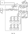
- FIG. 7A illustrates a high level block diagram of an embodiment of an electric vehicle fast charging station 200, where a first electrical vehicle is arranged to charge a second electrical vehicle.
- Electric vehicle fast charging station 200 is arranged as described above in relation to electric vehicle fast charging station 10, with the exception that DC/DC charging units 70 are replaced with bi-directional converters 210.
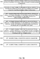
- FIG. 7B illustrates a high level flow chart of a method of operation of the arrangement of FIG. 7A to provide plug-in vehicle to plug-in vehicle charging, the figures being described together.
- FIGs. 7A - 7B are particularly described in relation to electrical vehicles, however this is meant as an illustrating embodiment, and is not meant to be limiting in any way.
- Electric vehicle fast charging station 200 may operate as described above in relation to electric vehicle fast charging station 100, and in addition may provide electrical energy drawn from a first PEV 80 to a second PEV 80.
- First PEV 80 is configured with the ability to provide electrical energy via its charging port to a first port of the respective bi-directional DC/DC converters 210 to which it is connected.
- Such arrangements are well known to those skilled in the art of Vehicle to Grid technology, and in the interest of brevity will not be further described.
- the bi-directional converter 210 coupled to first PEV 80 is arranged to draw electrical energy from first PEV 80 through a first port of the respective bi-directional converter 210 and provide the drawn electrical energy to DC bus 60 through a second port of the respective bi-directional converter 210, as shown by the respective arrow.
- the bi-directional converter 210 coupled to second PEV 80 is arranged to draw electrical energy from DC bus 60 through a second port of the respective bi-directional converter 210 and provide the drawn electrical energy to second PEV 80 through a first port of the respective bi-directional converter 210, thus charging second PEV 80 from the on-board storage of first PEV 80 as shown by the respective arrow.
- the amount of electrical energy provided to DC bus 60 from first PEV 80 is substantially identical to the amount of electrical energy drawn from DC bus 60 to be provided to second PEV 80, and thus there is no electrical energy drawn from AC grid 15 or from electrical storage units 50 while still charging second PEV 80. Since each of bi-directional DC/DC converters 210 experience a certain amount of loss, any determination of amounts of electrical energy are preferably determined at the respective second port thereof, as determined by the respective current sensor 55.
- the amount of electrical energy provided to DC bus 60 from first PEV 80 is less than the amount of electrical energy drawn from DC bus 60 to be provided to second PEV 80, and thus the difference in energy required to charge second PEV 80 is drawn from AC grid 15 and/or from electrical storage units 50.
- the amount of electrical energy provided to DC bus 60 from first PEV 80 is greater than the amount of electrical energy drawn from DC bus 60 to be provided to second PEV 80, and thus the difference in energy is stored on electrical storage units 50, and/or provided to AC grid 15.
- each of the bidirectional converters 210 are DC/DC converters, as illustrated in optional stage 5050, however this is not meant to be limiting in any way.
- electric vehicle fast charging station 100 may be modified by replacing AC/DC charging units 130 with bi-directional AC/DC converters, as illustrated in optional stage 5060.
Landscapes
- Engineering & Computer Science (AREA)
- Power Engineering (AREA)
- Transportation (AREA)
- Mechanical Engineering (AREA)
- Charge And Discharge Circuits For Batteries Or The Like (AREA)
- Electric Propulsion And Braking For Vehicles (AREA)
- Supply And Distribution Of Alternating Current (AREA)
Claims (15)
- Station comprenant :un circuit de commande (30) ;une interface bidirectionnelle (40) pour le couplage à un réseau électrique de courant alternatif (15) ; etune pluralité de N unités de stockage électrique par volant d'inertie (50) couplées à ladite interface bidirectionnelle,caractérisée en ce que ledit circuit de commande est agencé pour :déterminer (2000) une demande de puissance électrique d'une quantité Preq ;déterminer (2000) une quantité maximale de courant d'ondulation autorisée ;déterminer (2010) la puissance disponible à partir de chaque unité de stockage électrique par volant d'inertie de ladite pluralité de N unités de stockage électrique par volant d'inertie ;sélectionner (2030) M + 1 de ladite pluralité d'unités de stockage électrique par volant d'inertie ayant la puissance disponible déterminée la plus élevée de sorte que la puissance disponible parmi les M sélectionnées de ladite pluralité d'unités de stockage électrique par volant d'inertie soit inférieure à Preq, et que la puissance disponible parmi les M + 1 sélectionnées de ladite pluralité d'unités de stockage électrique par volant d'inertie soit supérieure ou égale à Preq ;déterminer (2040) le changement souhaité du courant de sortie pour chaque unité de stockage électrique par volant d'inertie de ladite N pluralité d'unités de stockage électrique par volant d'inertie ;réduire (2050) le courant de sortie d'une unité de stockage électrique par volant d'inertie de ladite N pluralité d'unités de stockage électrique par volant d'inertie pour lequel ladite détermination indique un changement souhaité négatif jusqu'au courant d'ondulation maximum déterminé ;augmenter (2060) le courant de sortie d'une unité de stockage électrique par volant d'inertie de ladite N pluralité d'unités de stockage électrique par volant d'inertie pour lequel ladite détermination indique un changement souhaité positif jusqu'au courant d'ondulation maximum déterminé ;comparer (2070) le courant de sortie de ladite N pluralité d'unités de stockage électrique par volant d'inertie auxdits changements souhaités déterminés ; etrépéter (2070) ladite réduction, augmentation et comparaison jusqu'à ce que ledit changement souhaité déterminé de courant de sortie pour chaque unité de stockage électrique par volant d'inertie de ladite N pluralité d'unités de stockage électrique par volant d'inertie soit mise en œuvre.
- Station selon la revendication 1, dans laquelle ladite interface bidirectionnelle comprend un convertisseur CA/CC bidirectionnel (40), et la station comprenant en outre :
au moins une unité de charge CA/CC (130) et/ou une unité de charge CC/CC (70) couplée audit convertisseur CA/CC bidirectionnel et agencée pour être couplée à une fiche dans un véhicule électrique (80). - Station selon la revendication 2, dans laquelle ledit circuit de commande est en outre en communication avec un opérateur de service de distribution (20), ledit circuit de commande étant agencé pour fournir (2000) de la puissance au réseau électrique de courant alternatif en réponse à une première demande du service de distribution, et la puissance consommée (3000) du réseau électrique de courant alternatif en réponse à une seconde demande de l'opérateur de service de distribution, et dans laquelle ledit circuit de commande est en outre agencé pour allouer une capacité de stockage de ladite pluralité de N unités de stockage électrique par volant d'inertie parmi :une première partie allouée pour fournir de la puissance à ladite au moins une unité de charge CA/CC ou unité de charge CC/CC ;une deuxième partie allouée pour absorber l'énergie électrique provenant dudit réseau électrique de courant alternatif ; etune troisième portion allouée pour fournir de l'énergie électrique audit réseau électrique de courant alternatif.
- Station selon la revendication 3, dans laquelle lesdites première partie, deuxième partie et troisième partie sont allouées (1040) en réponse à des données historiques.
- Système selon la revendication 1, comprenant en outre :une unité de charge CC/CC (70) agencée pour être couplée à une fiche dans un véhicule électrique (80), et dans laquelle ladite interface bidirectionnelle comprend un convertisseur CA/CC bidirectionnel (40),chaque unité de stockage électrique par volant d'inertie de ladite pluralité d'unités de stockage électrique par volant d'inertie étant couplée à un bus CC commun (60) pour fournir de la puissance à ladite unité de charge CC/CC et pour fournir de la puissance audit convertisseur CA/CC bidirectionnel ou pour recevoir de la puissance de celui-ci.
- Système selon la revendication 5, comprenant en outre :un capteur de tension (65) couplé au bus CC commun et en communication avec ledit circuit de commande ;un capteur de courant (55) couplé à l'unité de charge CC/CC et en communication avec ledit circuit de commande ; etun capteur de puissance (35) couplé au convertisseur CA/CC bidirectionnel et en communication avec ledit circuit de commande, ledit circuit de commande étant agencé pour déterminer (4010) la quantité de puissance consommée par la station ou fournie par celle-ci en réponse audit capteur de puissance couplé au convertisseur CA/CC bidirectionnel.
- Système selon la revendication 1, comprenant en outre :une unité de charge CA/CC (130) agencée pour être couplée à une prise dans un véhicule électrique (80), et dans laquelle ladite interface bidirectionnelle comprend un convertisseur CA/CC bidirectionnel, ladite unité de charge CA/CC étant couplée à un nœud commun de la station,chaque unité de stockage électrique par volant d'inertie de ladite pluralité d'unités de stockage électrique par volant d'inertie étant couplée à un bus CC commun pour fournir de la puissance audit convertisseur CA/CC bidirectionnel ou pour recevoir de la puissance de celui-ci ;un premier capteur de puissance couplé entre le réseau électrique de courant alternatif et le nœud commun, ledit premier capteur de puissance étant en communication avec ledit circuit de commande ; etun second capteur de puissance couplé entre le nœud commun et ledit convertisseur CA/CC bidirectionnel, ledit second capteur de puissance étant en communication avec ledit circuit de commande.
- Station selon l'une quelconque des revendications 1, 2 et 5-7, dans laquelle ledit circuit de commande est en outre agencé pour :déterminer (3000) une quantité de puissance à stocker, Pavail ;déterminer (3000) une quantité maximale de courant d'ondulation autorisée ;déterminer (3010) le stockage de puissance disponible à partir de chaque unité de stockage électrique par volant d'inertie de ladite pluralité de N unités de stockage électrique par volant d'inertie ;sélectionner (3030) M + 1 de ladite pluralité d'unités de stockage électrique par volant d'inertie ayant la puissance disponible déterminée la plus basse de sorte que la puissance disponible parmi les M sélectionnées de ladite pluralité d'unités de stockage électrique par volant d'inertie soit supérieure à Pavail, et que la puissance disponible parmi les M + 1 sélectionnées de ladite pluralité d'unités de stockage électrique par volant d'inertie soit inférieure ou égale à Pavail ;déterminer (3040) le changement souhaité du courant de sortie pour chaque unité de stockage électrique par volant d'inertie de ladite N pluralité d'unités de stockage électrique par volant d'inertie ;augmenter (3050) le courant de sortie de l'une de ladite pluralité d'unités N de stockage électrique à volant d'inertie pour lequel ladite détermination indique un changement positif souhaité jusqu'au courant d'ondulation maximum déterminé ;diminuer (3060) le courant de sortie d'une unité de stockage électrique par volant d'inertie de ladite N pluralité d'unités de stockage électrique par volant d'inertie pour lequel ladite détermination indique un changement souhaité négatif jusqu'au courant d'ondulation maximum déterminé ;comparer (3070) le courant de sortie de ladite N pluralité d'unités de stockage électrique par volant d'inertie auxdits changements souhaités déterminés ; etrépéter (3070) ladite augmentation, réduction et comparaison jusqu'à ce que ledit changement souhaité déterminé de courant de sortie pour chaque unité de stockage électrique par volant d'inertie de ladite N pluralité d'unités de stockage électrique par volant d'inertie soit mise en œuvre.
- Station selon l'une quelconque des revendications 1, 2 et 5 à 7, dans laquelle ledit circuit de commande est en outre en communication avec un opérateur de service de distribution (20), ledit circuit de commande étant agencé pour fournir de la puissance au réseau électrique de courant alternatif en réponse à une première demande de l'opérateur de service de distribution, et pour consommer de la puissance du réseau électrique de courant alternatif en réponse à une seconde demande de l'opérateur de service de distribution.
- Procédé de commande d'une pluralité de N unités de stockage électrique par volant d'inertie (50), caractérisé par :la détermination (2000) d'une demande de puissance électrique d'une quantité Preq ;la détermination (2000) d'une quantité maximale de courant d'ondulation autorisée ;la détermination (2010) de la puissance disponible à partir de chaque unité de stockage électrique par volant d'inertie de la pluralité de N unités de stockage électrique par volant d'inertie ;la sélection (2030) de M + 1 de ladite pluralité d'unités de stockage électrique par volant d'inertie ayant la puissance disponible déterminée la plus élevée de sorte que la puissance disponible parmi les M sélectionnées de ladite pluralité d'unités de stockage électrique par volant d'inertie soit inférieure à Preq, et que la puissance disponible parmi les M + 1 sélectionnées de ladite pluralité d'unités de stockage électrique par volant d'inertie soit supérieure ou égale à Preq ;la détermination (2040) du changement souhaité du courant de sortie pour chaque unité de stockage électrique par volant d'inertie de ladite N pluralité d'unités de stockage électrique par volant d'inertie ;la réduction (2050) du courant de sortie de l'une de ladite N pluralité d'unités de stockage électrique par volant d'inertie pour lequel ladite détermination indique un changement souhaité négatif jusqu'au courant d'ondulation maximum déterminé ;l'augmentation (2060) du courant de sortie d'une unité de stockage électrique par volant d'inertie de ladite N pluralité d'unités de stockage électrique par volant d'inertie pour lequel ladite détermination indique un changement souhaité positif jusqu'au courant d'ondulation maximum déterminé ;la comparaison (2070) du courant de sortie de ladite N pluralité d'unités de stockage électrique par volant d'inertie auxdits changements souhaités déterminés ; etla répétition (2070) de ladite réduction, augmentation et comparaison jusqu'à ce que ledit changement souhaité déterminé de courant de sortie pour chaque unité de stockage électrique par volant d'inertie de ladite N pluralité d'unités de stockage électrique par volant d'inertie soit mise en œuvre.
- Procédé selon la revendication 10, comprenant en outre :la fourniture (2000) d'une puissance à un réseau électrique de courant alternatif en réponse à une première demande d'un opérateur de service de distribution (20) ;la consommation (3000) d'une puissance provenant du réseau électrique de courant alternatif en réponse à une seconde demande de l'opérateur de service de distribution ; etl'allocation d'une capacité de stockage de ladite pluralité de N unités de stockage électrique par volant d'inertie parmi :une première partie allouée pour fournir de la puissance à l'au moins une unité de charge CA/CC ou unité de charge CC/CC ;une deuxième partie allouée pour absorber l'énergie électrique provenant dudit réseau électrique de courant alternatif ; etune troisième portion allouée pour fournir de l'énergie électrique audit réseau électrique de courant alternatif.
- Procédé selon la revendication 11, dans lequel lesdites première partie, deuxième partie et troisième partie sont allouées (104) en réponse à des données historiques.
- Procédé selon l'une quelconque des revendications 10 à 12, comprenant en outre :la détermination (3000) d'une quantité de puissance à stocker, Pavail ;la détermination (3000) d'une quantité maximale de courant d'ondulation autorisée ;la détermination (3010) du stockage de puissance disponible à partir de chaque unité de stockage électrique par volant d'inertie de ladite pluralité de N unités de stockage électrique par volant d'inertie ;la sélection de M + 1 (3 030) de ladite pluralité d'unités de stockage électrique par volant d'inertie ayant la puissance disponible déterminée la plus basse de sorte que la puissance disponible parmi les M sélectionnées de ladite pluralité d'unités de stockage électrique par volant d'inertie soit supérieure à Pavail, et que la puissance disponible parmi les M + 1 sélectionnées de ladite pluralité d'unités de stockage électrique par volant d'inertie soit inférieure ou égale à Pavail ;la détermination (3040) du changement souhaité du courant de sortie pour chaque unité de stockage électrique par volant d'inertie de ladite N pluralité d'unités de stockage électrique par volant d'inertie ;l'augmentation (3050) du courant de sortie d'une unité de stockage électrique par volant d'inertie de ladite N pluralité d'unités de stockage électrique par volant d'inertie pour lequel ladite détermination indique un changement souhaité positif jusqu'au courant d'ondulation maximum déterminé ;la diminution (3060) du courant de sortie d'une unité de stockage électrique par volant d'inertie de ladite N pluralité d'unités de stockage électrique par volant d'inertie pour lequel ladite détermination indique un changement souhaité négatif jusqu'au courant d'ondulation maximum déterminé ;la comparaison (3070) du courant de sortie de ladite N pluralité d'unités de stockage électrique par volant d'inertie auxdits changements souhaités déterminés ; etla répétition (3070) de ladite augmentation, réduction et comparaison jusqu'à ce que ledit changement souhaité déterminé de courant de sortie pour chaque unité de stockage électrique par volant d'inertie de ladite N pluralité d'unités de stockage électrique par volant d'inertie soit mise en œuvre.
- Procédé selon la revendication 10, comprenant en outre :la fourniture d'une puissance au réseau électrique de courant alternatif en réponse à une première demande d'un opérateur de service de distribution (20) ; etla consommation d'une puissance provenant du réseau électrique de courant alternatif en réponse à une seconde demande de l'opérateur de service de distribution.
- Procédé selon la revendication 13, comprenant en outre :la fourniture (2000) d'une puissance au réseau électrique de courant alternatif en réponse à une première demande de l'opérateur de service de distribution ; etla consommation (3000) d'une puissance provenant du réseau électrique de courant alternatif en réponse à une seconde demande de l'opérateur de service de distribution.
Applications Claiming Priority (2)
| Application Number | Priority Date | Filing Date | Title |
|---|---|---|---|
| US201662414747P | 2016-10-30 | 2016-10-30 | |
| PCT/IL2017/051170 WO2018078625A2 (fr) | 2016-10-30 | 2017-10-25 | Système et procédé pour une station fournissant un support de réseau électrique |
Publications (2)
| Publication Number | Publication Date |
|---|---|
| EP3532337A2 EP3532337A2 (fr) | 2019-09-04 |
| EP3532337B1 true EP3532337B1 (fr) | 2020-03-18 |
Family
ID=60320939
Family Applications (1)
| Application Number | Title | Priority Date | Filing Date |
|---|---|---|---|
| EP17797760.0A Active EP3532337B1 (fr) | 2016-10-30 | 2017-10-25 | Système et procédé pour une station fournissant un support de réseau électrique |
Country Status (6)
| Country | Link |
|---|---|
| US (3) | US11034255B2 (fr) |
| EP (1) | EP3532337B1 (fr) |
| CN (1) | CN110167787B (fr) |
| CA (1) | CA3079939A1 (fr) |
| IL (1) | IL266291B (fr) |
| WO (1) | WO2018078625A2 (fr) |
Cited By (1)
| Publication number | Priority date | Publication date | Assignee | Title |
|---|---|---|---|---|
| DE102020216555A1 (de) | 2020-12-23 | 2022-06-23 | Adaptive Balancing Power GmbH | Ladestation zum Laden von Elektrofahrzeugen mit einer elektrischen Ladeleistung von mehr als 100 kW |
Families Citing this family (9)
| Publication number | Priority date | Publication date | Assignee | Title |
|---|---|---|---|---|
| JP2017518725A (ja) * | 2014-06-20 | 2017-07-06 | ゼネラル・エレクトリック・カンパニイ | エネルギ貯蔵充電ステーション用の電力制御のシステムおよび方法 |
| DE102018102566A1 (de) * | 2018-02-06 | 2019-08-08 | Dr. Ing. H.C. F. Porsche Aktiengesellschaft | Ladesystem mit mindestens einer Ladesäule für Elektrofahrzeuge und Verfahren zum Laden eines oder mehrerer Elektrofahrzeuge |
| EP3890137A4 (fr) * | 2018-11-28 | 2022-08-24 | Kyocera Corporation | Dispositif de gestion d'énergie, procédé de gestion d'énergie, et système de gestion d'énergie |
| US11897349B2 (en) | 2019-02-13 | 2024-02-13 | DRiV Automotive Inc. | Soft hitch vehicle platooning system |
| EP4044399A4 (fr) * | 2019-10-07 | 2023-01-18 | Honda Motor Co., Ltd. | Système de charge |
| CN110544949A (zh) * | 2019-10-12 | 2019-12-06 | 沈阳远大电力电子科技有限公司 | 一种电能转换系统 |
| CN112440806B (zh) * | 2020-11-23 | 2022-08-09 | 南方电网调峰调频发电有限公司 | 充电桩的功率控制方法、装置、计算机设备及存储介质 |
| RU2762457C1 (ru) * | 2021-04-07 | 2021-12-21 | Алексей Вячеславович Зотов | Мобильное устройство быстрой зарядки электротранспорта |
| CN113386607B (zh) * | 2021-05-26 | 2023-04-07 | 浙江吉利控股集团有限公司 | 一种充电站充放电自动平衡方法、装置及充电站 |
Family Cites Families (28)
| Publication number | Priority date | Publication date | Assignee | Title |
|---|---|---|---|---|
| EP0736828A3 (fr) | 1995-04-06 | 1997-11-12 | Seiko Epson Corporation | Dispositif électronique alimenté par batterie et procédé de commande de l'alimentation dans le dispositif |
| US5786682A (en) | 1996-08-07 | 1998-07-28 | Reltec Corporation | Battery charging circuit including a current limiter which compares a reference current to a charging current to ensure operation of a load |
| JP3388179B2 (ja) | 1998-04-08 | 2003-03-17 | 株式会社ケンウッド | 車両検知装置 |
| US6246214B1 (en) | 2000-05-10 | 2001-06-12 | Motorola, Inc. | Multiple use of a single transistor for linear regulation charge control and protection of a rechargeable battery |
| US6525594B2 (en) | 2000-08-21 | 2003-02-25 | Texas Instruments Incorporated | Eliminating power-down popping in audio power amplifiers |
| US20020036430A1 (en) * | 2000-09-28 | 2002-03-28 | Welches Richard S. | Local area grid for distributed power |
| FR2819759B1 (fr) * | 2001-01-24 | 2003-05-23 | Alstom | Systeme d'alimentation d'un vehicule a traction electrique |
| CA2374342C (fr) | 2001-03-01 | 2005-12-20 | Research In Motion Limited | Systeme et methode d'alimentation et de charge d'un dispositif de communication mobile |
| US6507172B2 (en) | 2001-03-19 | 2003-01-14 | Maxim Integrated Products, Inc. | Universal serial bus powered battery charger |
| US6861824B1 (en) | 2002-07-10 | 2005-03-01 | Arquesttechnology, Inc. | Charger system with dual-level current regulation and dual-level thermal regulation |
| TW200413895A (en) | 2002-10-15 | 2004-08-01 | Powerdsine Ltd | Direct current power pooling |
| US7528582B1 (en) | 2003-01-21 | 2009-05-05 | Microsemi Corp. | Battery charging and discharging by using a bi-directional transistor |
| US7443049B1 (en) * | 2005-08-02 | 2008-10-28 | Yazaki North America, Inc. | Bi-directional inverter control for high voltage charge/discharge for automobiles |
| CN101647170B (zh) * | 2006-11-16 | 2013-11-13 | 康明斯发电Ip公司 | 发电系统及方法 |
| US8872379B2 (en) | 2007-11-30 | 2014-10-28 | Johnson Controls Technology Company | Efficient usage, storage, and sharing of energy in buildings, vehicles, and equipment |
| US9093862B2 (en) | 2009-01-16 | 2015-07-28 | Zbb Energy Corporation | Method and apparatus for controlling a hybrid power system |
| US8294420B2 (en) | 2009-09-29 | 2012-10-23 | Schneider Electric USA, Inc. | Kiosk vehicle charging and selecting systems |
| US8421419B2 (en) * | 2009-09-30 | 2013-04-16 | General Electric Company | Antiferroelectric capacitor-enabled power converter |
| DE102009055845A1 (de) * | 2009-11-26 | 2011-06-01 | Schaeffler Technologies Gmbh & Co. Kg | Aufladestation für elektrisch betriebene Fahrzeuge |
| US20110276194A1 (en) | 2010-05-10 | 2011-11-10 | Emalfarb Hal A | System and method for energy management |
| US20120074901A1 (en) * | 2010-09-27 | 2012-03-29 | Tim Mohammed | Centralized charging station |
| JP6050757B2 (ja) | 2010-11-15 | 2016-12-21 | ブルーム エナジー コーポレーション | 直流マイクログリッド機能を備えた自立運転可能な燃料電池システム |
| EP2647522B1 (fr) * | 2012-04-03 | 2020-01-22 | Enrichment Technology Company Ltd. | Station-service électrique avec stations de charge rapide |
| ES2901007T3 (es) | 2012-07-30 | 2022-03-21 | Chakratec Ltd | Volante de inercia acoplado magnéticamente |
| CN203119680U (zh) * | 2012-12-26 | 2013-08-07 | 江阴市振江钢结构有限公司 | 一种飞轮储能装置的测试系统 |
| FR3015802B1 (fr) | 2013-12-23 | 2016-02-05 | Evtronic | Bloc d'alimentation electrique compact et modulaire, multi-convertisseurs, notamment pour bornes de recharge rapide de vehicules electriques |
| JP2016116401A (ja) * | 2014-12-17 | 2016-06-23 | 株式会社ピューズ | 電力負荷平準化装置 |
| CN105515128A (zh) * | 2016-02-04 | 2016-04-20 | 李舒曼 | 智能化电动汽车充电站 |
-
2017
- 2017-10-25 EP EP17797760.0A patent/EP3532337B1/fr active Active
- 2017-10-25 WO PCT/IL2017/051170 patent/WO2018078625A2/fr active Application Filing
- 2017-10-25 CA CA3079939A patent/CA3079939A1/fr active Pending
- 2017-10-25 CN CN201780080085.0A patent/CN110167787B/zh active Active
- 2017-10-25 US US16/345,711 patent/US11034255B2/en active Active
-
2019
- 2019-04-28 IL IL266291A patent/IL266291B/en active IP Right Grant
-
2021
- 2021-06-07 US US17/340,329 patent/US11400826B2/en active Active
-
2022
- 2022-07-25 US US17/872,058 patent/US11691528B2/en active Active
Non-Patent Citations (1)
| Title |
|---|
| None * |
Cited By (2)
| Publication number | Priority date | Publication date | Assignee | Title |
|---|---|---|---|---|
| DE102020216555A1 (de) | 2020-12-23 | 2022-06-23 | Adaptive Balancing Power GmbH | Ladestation zum Laden von Elektrofahrzeugen mit einer elektrischen Ladeleistung von mehr als 100 kW |
| WO2022136668A1 (fr) | 2020-12-23 | 2022-06-30 | Adaptive Balancing Power GmbH | Station de charge pour charger des véhicules électriques ayant une capacité de charge électrique supérieure à 100 kw |
Also Published As
| Publication number | Publication date |
|---|---|
| CN110167787A (zh) | 2019-08-23 |
| US20190351781A1 (en) | 2019-11-21 |
| IL266291A (en) | 2019-06-30 |
| US11400826B2 (en) | 2022-08-02 |
| US11691528B2 (en) | 2023-07-04 |
| IL266291B (en) | 2020-08-31 |
| WO2018078625A3 (fr) | 2018-07-26 |
| EP3532337A2 (fr) | 2019-09-04 |
| CN110167787B (zh) | 2022-12-09 |
| CA3079939A1 (fr) | 2018-05-03 |
| US20220355689A1 (en) | 2022-11-10 |
| US11034255B2 (en) | 2021-06-15 |
| US20210291689A1 (en) | 2021-09-23 |
| WO2018078625A2 (fr) | 2018-05-03 |
Similar Documents
| Publication | Publication Date | Title |
|---|---|---|
| EP3532337B1 (fr) | Système et procédé pour une station fournissant un support de réseau électrique | |
| US9948119B2 (en) | Control of parallel battery utilization | |
| EP3718073A1 (fr) | Cadriciel et procédés d'optimisation de charge adaptative d'ev | |
| WO2012017937A1 (fr) | Système d'égalisation de la demande et de la fourniture d'énergie | |
| US20160352111A1 (en) | Control system for electric storage system | |
| JP6947896B2 (ja) | 蓄電装置 | |
| US20160114694A1 (en) | Storage cell management apparatus | |
| WO2011105580A1 (fr) | Système de chargement, appareil de charge/décharge et procédé de commande de charge/décharge | |
| JP6523184B2 (ja) | 蓄電装置、及び電力供給システムの管理サーバー | |
| US20160280091A1 (en) | Managing the exchange of electrical power with rechargeable vehicle batteries in v2x systems | |
| US20170005483A1 (en) | Battery Control Apparatus | |
| US9669720B2 (en) | Managing the exchange of electrical power with rechargeable vehicle batteries in V2X systems | |
| CN110890760B (zh) | 用于操作电能存储装置的方法和控制设备 | |
| US20210376611A1 (en) | A method and system for power balancing | |
| US20240001794A1 (en) | Power arrangement, method for providing electrical power and computer program product | |
| JP7181036B2 (ja) | 電力供給システム | |
| JP7219572B2 (ja) | 電力供給システム | |
| CN117507919B (zh) | 一种将交直流一体化控制实现有序充电的方法及系统 | |
| WO2015145818A1 (fr) | Dispositif de commande de réglage d'énergie et procédé de commande de réglage d'énergie | |
| TWM639040U (zh) | 電動車隊充電管理系統 |
Legal Events
| Date | Code | Title | Description |
|---|---|---|---|
| STAA | Information on the status of an ep patent application or granted ep patent |
Free format text: STATUS: UNKNOWN |
|
| STAA | Information on the status of an ep patent application or granted ep patent |
Free format text: STATUS: THE INTERNATIONAL PUBLICATION HAS BEEN MADE |
|
| PUAI | Public reference made under article 153(3) epc to a published international application that has entered the european phase |
Free format text: ORIGINAL CODE: 0009012 |
|
| STAA | Information on the status of an ep patent application or granted ep patent |
Free format text: STATUS: REQUEST FOR EXAMINATION WAS MADE |
|
| REG | Reference to a national code |
Ref country code: DE Ref legal event code: R079 Ref document number: 602017013383 Country of ref document: DE Free format text: PREVIOUS MAIN CLASS: B60L0011180000 Ipc: B60L0053310000 |
|
| 17P | Request for examination filed |
Effective date: 20190528 |
|
| AK | Designated contracting states |
Kind code of ref document: A2 Designated state(s): AL AT BE BG CH CY CZ DE DK EE ES FI FR GB GR HR HU IE IS IT LI LT LU LV MC MK MT NL NO PL PT RO RS SE SI SK SM TR |
|
| AX | Request for extension of the european patent |
Extension state: BA ME |
|
| RIC1 | Information provided on ipc code assigned before grant |
Ipc: B60L 53/31 20190101AFI20190815BHEP Ipc: B60L 53/56 20190101ALI20190815BHEP |
|
| GRAP | Despatch of communication of intention to grant a patent |
Free format text: ORIGINAL CODE: EPIDOSNIGR1 |
|
| STAA | Information on the status of an ep patent application or granted ep patent |
Free format text: STATUS: GRANT OF PATENT IS INTENDED |
|
| DAV | Request for validation of the european patent (deleted) | ||
| DAX | Request for extension of the european patent (deleted) | ||
| INTG | Intention to grant announced |
Effective date: 20191014 |
|
| GRAS | Grant fee paid |
Free format text: ORIGINAL CODE: EPIDOSNIGR3 |
|
| GRAA | (expected) grant |
Free format text: ORIGINAL CODE: 0009210 |
|
| STAA | Information on the status of an ep patent application or granted ep patent |
Free format text: STATUS: THE PATENT HAS BEEN GRANTED |
|
| AK | Designated contracting states |
Kind code of ref document: B1 Designated state(s): AL AT BE BG CH CY CZ DE DK EE ES FI FR GB GR HR HU IE IS IT LI LT LU LV MC MK MT NL NO PL PT RO RS SE SI SK SM TR |
|
| REG | Reference to a national code |
Ref country code: GB Ref legal event code: FG4D |
|
| REG | Reference to a national code |
Ref country code: DE Ref legal event code: R096 Ref document number: 602017013383 Country of ref document: DE |
|
| REG | Reference to a national code |
Ref country code: AT Ref legal event code: REF Ref document number: 1245535 Country of ref document: AT Kind code of ref document: T Effective date: 20200415 Ref country code: IE Ref legal event code: FG4D |
|
| PG25 | Lapsed in a contracting state [announced via postgrant information from national office to epo] |
Ref country code: RS Free format text: LAPSE BECAUSE OF FAILURE TO SUBMIT A TRANSLATION OF THE DESCRIPTION OR TO PAY THE FEE WITHIN THE PRESCRIBED TIME-LIMIT Effective date: 20200318 Ref country code: FI Free format text: LAPSE BECAUSE OF FAILURE TO SUBMIT A TRANSLATION OF THE DESCRIPTION OR TO PAY THE FEE WITHIN THE PRESCRIBED TIME-LIMIT Effective date: 20200318 Ref country code: NO Free format text: LAPSE BECAUSE OF FAILURE TO SUBMIT A TRANSLATION OF THE DESCRIPTION OR TO PAY THE FEE WITHIN THE PRESCRIBED TIME-LIMIT Effective date: 20200618 |
|
| REG | Reference to a national code |
Ref country code: NL Ref legal event code: MP Effective date: 20200318 |
|
| PG25 | Lapsed in a contracting state [announced via postgrant information from national office to epo] |
Ref country code: HR Free format text: LAPSE BECAUSE OF FAILURE TO SUBMIT A TRANSLATION OF THE DESCRIPTION OR TO PAY THE FEE WITHIN THE PRESCRIBED TIME-LIMIT Effective date: 20200318 Ref country code: GR Free format text: LAPSE BECAUSE OF FAILURE TO SUBMIT A TRANSLATION OF THE DESCRIPTION OR TO PAY THE FEE WITHIN THE PRESCRIBED TIME-LIMIT Effective date: 20200619 Ref country code: BG Free format text: LAPSE BECAUSE OF FAILURE TO SUBMIT A TRANSLATION OF THE DESCRIPTION OR TO PAY THE FEE WITHIN THE PRESCRIBED TIME-LIMIT Effective date: 20200618 Ref country code: LV Free format text: LAPSE BECAUSE OF FAILURE TO SUBMIT A TRANSLATION OF THE DESCRIPTION OR TO PAY THE FEE WITHIN THE PRESCRIBED TIME-LIMIT Effective date: 20200318 Ref country code: SE Free format text: LAPSE BECAUSE OF FAILURE TO SUBMIT A TRANSLATION OF THE DESCRIPTION OR TO PAY THE FEE WITHIN THE PRESCRIBED TIME-LIMIT Effective date: 20200318 |
|
| REG | Reference to a national code |
Ref country code: LT Ref legal event code: MG4D |
|
| PG25 | Lapsed in a contracting state [announced via postgrant information from national office to epo] |
Ref country code: NL Free format text: LAPSE BECAUSE OF FAILURE TO SUBMIT A TRANSLATION OF THE DESCRIPTION OR TO PAY THE FEE WITHIN THE PRESCRIBED TIME-LIMIT Effective date: 20200318 |
|
| PG25 | Lapsed in a contracting state [announced via postgrant information from national office to epo] |
Ref country code: IS Free format text: LAPSE BECAUSE OF FAILURE TO SUBMIT A TRANSLATION OF THE DESCRIPTION OR TO PAY THE FEE WITHIN THE PRESCRIBED TIME-LIMIT Effective date: 20200718 Ref country code: RO Free format text: LAPSE BECAUSE OF FAILURE TO SUBMIT A TRANSLATION OF THE DESCRIPTION OR TO PAY THE FEE WITHIN THE PRESCRIBED TIME-LIMIT Effective date: 20200318 Ref country code: SK Free format text: LAPSE BECAUSE OF FAILURE TO SUBMIT A TRANSLATION OF THE DESCRIPTION OR TO PAY THE FEE WITHIN THE PRESCRIBED TIME-LIMIT Effective date: 20200318 Ref country code: CZ Free format text: LAPSE BECAUSE OF FAILURE TO SUBMIT A TRANSLATION OF THE DESCRIPTION OR TO PAY THE FEE WITHIN THE PRESCRIBED TIME-LIMIT Effective date: 20200318 Ref country code: LT Free format text: LAPSE BECAUSE OF FAILURE TO SUBMIT A TRANSLATION OF THE DESCRIPTION OR TO PAY THE FEE WITHIN THE PRESCRIBED TIME-LIMIT Effective date: 20200318 Ref country code: SM Free format text: LAPSE BECAUSE OF FAILURE TO SUBMIT A TRANSLATION OF THE DESCRIPTION OR TO PAY THE FEE WITHIN THE PRESCRIBED TIME-LIMIT Effective date: 20200318 Ref country code: PT Free format text: LAPSE BECAUSE OF FAILURE TO SUBMIT A TRANSLATION OF THE DESCRIPTION OR TO PAY THE FEE WITHIN THE PRESCRIBED TIME-LIMIT Effective date: 20200812 Ref country code: EE Free format text: LAPSE BECAUSE OF FAILURE TO SUBMIT A TRANSLATION OF THE DESCRIPTION OR TO PAY THE FEE WITHIN THE PRESCRIBED TIME-LIMIT Effective date: 20200318 |
|
| REG | Reference to a national code |
Ref country code: AT Ref legal event code: MK05 Ref document number: 1245535 Country of ref document: AT Kind code of ref document: T Effective date: 20200318 |
|
| REG | Reference to a national code |
Ref country code: DE Ref legal event code: R097 Ref document number: 602017013383 Country of ref document: DE |
|
| PLBE | No opposition filed within time limit |
Free format text: ORIGINAL CODE: 0009261 |
|
| STAA | Information on the status of an ep patent application or granted ep patent |
Free format text: STATUS: NO OPPOSITION FILED WITHIN TIME LIMIT |
|
| PG25 | Lapsed in a contracting state [announced via postgrant information from national office to epo] |
Ref country code: AT Free format text: LAPSE BECAUSE OF FAILURE TO SUBMIT A TRANSLATION OF THE DESCRIPTION OR TO PAY THE FEE WITHIN THE PRESCRIBED TIME-LIMIT Effective date: 20200318 Ref country code: DK Free format text: LAPSE BECAUSE OF FAILURE TO SUBMIT A TRANSLATION OF THE DESCRIPTION OR TO PAY THE FEE WITHIN THE PRESCRIBED TIME-LIMIT Effective date: 20200318 Ref country code: ES Free format text: LAPSE BECAUSE OF FAILURE TO SUBMIT A TRANSLATION OF THE DESCRIPTION OR TO PAY THE FEE WITHIN THE PRESCRIBED TIME-LIMIT Effective date: 20200318 Ref country code: IT Free format text: LAPSE BECAUSE OF FAILURE TO SUBMIT A TRANSLATION OF THE DESCRIPTION OR TO PAY THE FEE WITHIN THE PRESCRIBED TIME-LIMIT Effective date: 20200318 |
|
| 26N | No opposition filed |
Effective date: 20201221 |
|
| PG25 | Lapsed in a contracting state [announced via postgrant information from national office to epo] |
Ref country code: PL Free format text: LAPSE BECAUSE OF FAILURE TO SUBMIT A TRANSLATION OF THE DESCRIPTION OR TO PAY THE FEE WITHIN THE PRESCRIBED TIME-LIMIT Effective date: 20200318 |
|
| REG | Reference to a national code |
Ref country code: CH Ref legal event code: PL |
|
| PG25 | Lapsed in a contracting state [announced via postgrant information from national office to epo] |
Ref country code: MC Free format text: LAPSE BECAUSE OF FAILURE TO SUBMIT A TRANSLATION OF THE DESCRIPTION OR TO PAY THE FEE WITHIN THE PRESCRIBED TIME-LIMIT Effective date: 20200318 Ref country code: LU Free format text: LAPSE BECAUSE OF NON-PAYMENT OF DUE FEES Effective date: 20201025 |
|
| REG | Reference to a national code |
Ref country code: BE Ref legal event code: MM Effective date: 20201031 |
|
| PG25 | Lapsed in a contracting state [announced via postgrant information from national office to epo] |
Ref country code: LI Free format text: LAPSE BECAUSE OF NON-PAYMENT OF DUE FEES Effective date: 20201031 Ref country code: CH Free format text: LAPSE BECAUSE OF NON-PAYMENT OF DUE FEES Effective date: 20201031 Ref country code: BE Free format text: LAPSE BECAUSE OF NON-PAYMENT OF DUE FEES Effective date: 20201031 |
|
| PG25 | Lapsed in a contracting state [announced via postgrant information from national office to epo] |
Ref country code: IE Free format text: LAPSE BECAUSE OF NON-PAYMENT OF DUE FEES Effective date: 20201025 |
|
| PG25 | Lapsed in a contracting state [announced via postgrant information from national office to epo] |
Ref country code: TR Free format text: LAPSE BECAUSE OF FAILURE TO SUBMIT A TRANSLATION OF THE DESCRIPTION OR TO PAY THE FEE WITHIN THE PRESCRIBED TIME-LIMIT Effective date: 20200318 Ref country code: MT Free format text: LAPSE BECAUSE OF FAILURE TO SUBMIT A TRANSLATION OF THE DESCRIPTION OR TO PAY THE FEE WITHIN THE PRESCRIBED TIME-LIMIT Effective date: 20200318 Ref country code: CY Free format text: LAPSE BECAUSE OF FAILURE TO SUBMIT A TRANSLATION OF THE DESCRIPTION OR TO PAY THE FEE WITHIN THE PRESCRIBED TIME-LIMIT Effective date: 20200318 |
|
| PG25 | Lapsed in a contracting state [announced via postgrant information from national office to epo] |
Ref country code: MK Free format text: LAPSE BECAUSE OF FAILURE TO SUBMIT A TRANSLATION OF THE DESCRIPTION OR TO PAY THE FEE WITHIN THE PRESCRIBED TIME-LIMIT Effective date: 20200318 Ref country code: AL Free format text: LAPSE BECAUSE OF FAILURE TO SUBMIT A TRANSLATION OF THE DESCRIPTION OR TO PAY THE FEE WITHIN THE PRESCRIBED TIME-LIMIT Effective date: 20200318 |
|
| REG | Reference to a national code |
Ref country code: DE Ref legal event code: R081 Ref document number: 602017013383 Country of ref document: DE Owner name: ZOOZ POWER LTD, IL Free format text: FORMER OWNER: CHAKRATEC LTD., LOD, IL |
|
| P01 | Opt-out of the competence of the unified patent court (upc) registered |
Effective date: 20230514 |
|
| PG25 | Lapsed in a contracting state [announced via postgrant information from national office to epo] |
Ref country code: SI Free format text: LAPSE BECAUSE OF FAILURE TO SUBMIT A TRANSLATION OF THE DESCRIPTION OR TO PAY THE FEE WITHIN THE PRESCRIBED TIME-LIMIT Effective date: 20200318 |
|
| PGFP | Annual fee paid to national office [announced via postgrant information from national office to epo] |
Ref country code: GB Payment date: 20231020 Year of fee payment: 7 |
|
| PGFP | Annual fee paid to national office [announced via postgrant information from national office to epo] |
Ref country code: FR Payment date: 20231026 Year of fee payment: 7 Ref country code: DE Payment date: 20231020 Year of fee payment: 7 |