EP3532264B1 - Candle filter support and process for filtering polymer melts - Google Patents
Candle filter support and process for filtering polymer melts Download PDFInfo
- Publication number
- EP3532264B1 EP3532264B1 EP17835950.1A EP17835950A EP3532264B1 EP 3532264 B1 EP3532264 B1 EP 3532264B1 EP 17835950 A EP17835950 A EP 17835950A EP 3532264 B1 EP3532264 B1 EP 3532264B1
- Authority
- EP
- European Patent Office
- Prior art keywords
- cylindrical body
- filter
- polymer melt
- end portion
- holes
- Prior art date
- Legal status (The legal status is an assumption and is not a legal conclusion. Google has not performed a legal analysis and makes no representation as to the accuracy of the status listed.)
- Active
Links
Images





Classifications
-
- B—PERFORMING OPERATIONS; TRANSPORTING
- B01—PHYSICAL OR CHEMICAL PROCESSES OR APPARATUS IN GENERAL
- B01D—SEPARATION
- B01D29/00—Filters with filtering elements stationary during filtration, e.g. pressure or suction filters, not covered by groups B01D24/00 - B01D27/00; Filtering elements therefor
- B01D29/11—Filters with filtering elements stationary during filtration, e.g. pressure or suction filters, not covered by groups B01D24/00 - B01D27/00; Filtering elements therefor with bag, cage, hose, tube, sleeve or like filtering elements
- B01D29/13—Supported filter elements
- B01D29/15—Supported filter elements arranged for inward flow filtration
-
- B—PERFORMING OPERATIONS; TRANSPORTING
- B01—PHYSICAL OR CHEMICAL PROCESSES OR APPARATUS IN GENERAL
- B01D—SEPARATION
- B01D29/00—Filters with filtering elements stationary during filtration, e.g. pressure or suction filters, not covered by groups B01D24/00 - B01D27/00; Filtering elements therefor
- B01D29/11—Filters with filtering elements stationary during filtration, e.g. pressure or suction filters, not covered by groups B01D24/00 - B01D27/00; Filtering elements therefor with bag, cage, hose, tube, sleeve or like filtering elements
- B01D29/13—Supported filter elements
- B01D29/15—Supported filter elements arranged for inward flow filtration
- B01D29/21—Supported filter elements arranged for inward flow filtration with corrugated, folded or wound sheets
-
- B—PERFORMING OPERATIONS; TRANSPORTING
- B01—PHYSICAL OR CHEMICAL PROCESSES OR APPARATUS IN GENERAL
- B01D—SEPARATION
- B01D29/00—Filters with filtering elements stationary during filtration, e.g. pressure or suction filters, not covered by groups B01D24/00 - B01D27/00; Filtering elements therefor
- B01D29/11—Filters with filtering elements stationary during filtration, e.g. pressure or suction filters, not covered by groups B01D24/00 - B01D27/00; Filtering elements therefor with bag, cage, hose, tube, sleeve or like filtering elements
- B01D29/13—Supported filter elements
- B01D29/23—Supported filter elements arranged for outward flow filtration
-
- B—PERFORMING OPERATIONS; TRANSPORTING
- B01—PHYSICAL OR CHEMICAL PROCESSES OR APPARATUS IN GENERAL
- B01D—SEPARATION
- B01D29/00—Filters with filtering elements stationary during filtration, e.g. pressure or suction filters, not covered by groups B01D24/00 - B01D27/00; Filtering elements therefor
- B01D29/96—Filters with filtering elements stationary during filtration, e.g. pressure or suction filters, not covered by groups B01D24/00 - B01D27/00; Filtering elements therefor in which the filtering elements are moved between filtering operations; Particular measures for removing or replacing the filtering elements; Transport systems for filters
-
- B—PERFORMING OPERATIONS; TRANSPORTING
- B29—WORKING OF PLASTICS; WORKING OF SUBSTANCES IN A PLASTIC STATE IN GENERAL
- B29B—PREPARATION OR PRETREATMENT OF THE MATERIAL TO BE SHAPED; MAKING GRANULES OR PREFORMS; RECOVERY OF PLASTICS OR OTHER CONSTITUENTS OF WASTE MATERIAL CONTAINING PLASTICS
- B29B13/00—Conditioning or physical treatment of the material to be shaped
- B29B13/10—Conditioning or physical treatment of the material to be shaped by grinding, e.g. by triturating; by sieving; by filtering
-
- B—PERFORMING OPERATIONS; TRANSPORTING
- B29—WORKING OF PLASTICS; WORKING OF SUBSTANCES IN A PLASTIC STATE IN GENERAL
- B29C—SHAPING OR JOINING OF PLASTICS; SHAPING OF MATERIAL IN A PLASTIC STATE, NOT OTHERWISE PROVIDED FOR; AFTER-TREATMENT OF THE SHAPED PRODUCTS, e.g. REPAIRING
- B29C45/00—Injection moulding, i.e. forcing the required volume of moulding material through a nozzle into a closed mould; Apparatus therefor
- B29C45/17—Component parts, details or accessories; Auxiliary operations
- B29C45/1753—Cleaning or purging, e.g. of the injection unit
- B29C45/1755—Means for receiving or discharging purged material; Purge shields
-
- B—PERFORMING OPERATIONS; TRANSPORTING
- B29—WORKING OF PLASTICS; WORKING OF SUBSTANCES IN A PLASTIC STATE IN GENERAL
- B29C—SHAPING OR JOINING OF PLASTICS; SHAPING OF MATERIAL IN A PLASTIC STATE, NOT OTHERWISE PROVIDED FOR; AFTER-TREATMENT OF THE SHAPED PRODUCTS, e.g. REPAIRING
- B29C45/00—Injection moulding, i.e. forcing the required volume of moulding material through a nozzle into a closed mould; Apparatus therefor
- B29C45/17—Component parts, details or accessories; Auxiliary operations
- B29C45/20—Injection nozzles
- B29C45/24—Cleaning equipment
-
- B—PERFORMING OPERATIONS; TRANSPORTING
- B29—WORKING OF PLASTICS; WORKING OF SUBSTANCES IN A PLASTIC STATE IN GENERAL
- B29C—SHAPING OR JOINING OF PLASTICS; SHAPING OF MATERIAL IN A PLASTIC STATE, NOT OTHERWISE PROVIDED FOR; AFTER-TREATMENT OF THE SHAPED PRODUCTS, e.g. REPAIRING
- B29C48/00—Extrusion moulding, i.e. expressing the moulding material through a die or nozzle which imparts the desired form; Apparatus therefor
- B29C48/25—Component parts, details or accessories; Auxiliary operations
- B29C48/265—Support structures or bases for apparatus, e.g. frames
-
- B—PERFORMING OPERATIONS; TRANSPORTING
- B29—WORKING OF PLASTICS; WORKING OF SUBSTANCES IN A PLASTIC STATE IN GENERAL
- B29C—SHAPING OR JOINING OF PLASTICS; SHAPING OF MATERIAL IN A PLASTIC STATE, NOT OTHERWISE PROVIDED FOR; AFTER-TREATMENT OF THE SHAPED PRODUCTS, e.g. REPAIRING
- B29C48/00—Extrusion moulding, i.e. expressing the moulding material through a die or nozzle which imparts the desired form; Apparatus therefor
- B29C48/25—Component parts, details or accessories; Auxiliary operations
- B29C48/27—Cleaning; Purging; Avoiding contamination
- B29C48/2725—Cleaning; Purging; Avoiding contamination of filters
-
- B—PERFORMING OPERATIONS; TRANSPORTING
- B29—WORKING OF PLASTICS; WORKING OF SUBSTANCES IN A PLASTIC STATE IN GENERAL
- B29C—SHAPING OR JOINING OF PLASTICS; SHAPING OF MATERIAL IN A PLASTIC STATE, NOT OTHERWISE PROVIDED FOR; AFTER-TREATMENT OF THE SHAPED PRODUCTS, e.g. REPAIRING
- B29C48/00—Extrusion moulding, i.e. expressing the moulding material through a die or nozzle which imparts the desired form; Apparatus therefor
- B29C48/25—Component parts, details or accessories; Auxiliary operations
- B29C48/275—Recovery or reuse of energy or materials
- B29C48/277—Recovery or reuse of energy or materials of materials
-
- B—PERFORMING OPERATIONS; TRANSPORTING
- B29—WORKING OF PLASTICS; WORKING OF SUBSTANCES IN A PLASTIC STATE IN GENERAL
- B29C—SHAPING OR JOINING OF PLASTICS; SHAPING OF MATERIAL IN A PLASTIC STATE, NOT OTHERWISE PROVIDED FOR; AFTER-TREATMENT OF THE SHAPED PRODUCTS, e.g. REPAIRING
- B29C48/00—Extrusion moulding, i.e. expressing the moulding material through a die or nozzle which imparts the desired form; Apparatus therefor
- B29C48/25—Component parts, details or accessories; Auxiliary operations
- B29C48/36—Means for plasticising or homogenising the moulding material or forcing it through the nozzle or die
- B29C48/50—Details of extruders
- B29C48/503—Extruder machines or parts thereof characterised by the material or by their manufacturing process
-
- B—PERFORMING OPERATIONS; TRANSPORTING
- B29—WORKING OF PLASTICS; WORKING OF SUBSTANCES IN A PLASTIC STATE IN GENERAL
- B29C—SHAPING OR JOINING OF PLASTICS; SHAPING OF MATERIAL IN A PLASTIC STATE, NOT OTHERWISE PROVIDED FOR; AFTER-TREATMENT OF THE SHAPED PRODUCTS, e.g. REPAIRING
- B29C48/00—Extrusion moulding, i.e. expressing the moulding material through a die or nozzle which imparts the desired form; Apparatus therefor
- B29C48/25—Component parts, details or accessories; Auxiliary operations
- B29C48/36—Means for plasticising or homogenising the moulding material or forcing it through the nozzle or die
- B29C48/50—Details of extruders
- B29C48/69—Filters or screens for the moulding material
- B29C48/691—Arrangements for replacing filters, e.g. with two parallel filters for alternate use
- B29C48/6912—Arrangements for replacing filters, e.g. with two parallel filters for alternate use the filters being fitted on a single rectilinearly reciprocating slide
-
- B—PERFORMING OPERATIONS; TRANSPORTING
- B29—WORKING OF PLASTICS; WORKING OF SUBSTANCES IN A PLASTIC STATE IN GENERAL
- B29C—SHAPING OR JOINING OF PLASTICS; SHAPING OF MATERIAL IN A PLASTIC STATE, NOT OTHERWISE PROVIDED FOR; AFTER-TREATMENT OF THE SHAPED PRODUCTS, e.g. REPAIRING
- B29C48/00—Extrusion moulding, i.e. expressing the moulding material through a die or nozzle which imparts the desired form; Apparatus therefor
- B29C48/25—Component parts, details or accessories; Auxiliary operations
- B29C48/36—Means for plasticising or homogenising the moulding material or forcing it through the nozzle or die
- B29C48/50—Details of extruders
- B29C48/69—Filters or screens for the moulding material
- B29C48/694—Cylindrical or conical filters
-
- C—CHEMISTRY; METALLURGY
- C22—METALLURGY; FERROUS OR NON-FERROUS ALLOYS; TREATMENT OF ALLOYS OR NON-FERROUS METALS
- C22C—ALLOYS
- C22C38/00—Ferrous alloys, e.g. steel alloys
- C22C38/18—Ferrous alloys, e.g. steel alloys containing chromium
- C22C38/40—Ferrous alloys, e.g. steel alloys containing chromium with nickel
- C22C38/44—Ferrous alloys, e.g. steel alloys containing chromium with nickel with molybdenum or tungsten
-
- C—CHEMISTRY; METALLURGY
- C22—METALLURGY; FERROUS OR NON-FERROUS ALLOYS; TREATMENT OF ALLOYS OR NON-FERROUS METALS
- C22C—ALLOYS
- C22C38/00—Ferrous alloys, e.g. steel alloys
- C22C38/18—Ferrous alloys, e.g. steel alloys containing chromium
- C22C38/40—Ferrous alloys, e.g. steel alloys containing chromium with nickel
- C22C38/50—Ferrous alloys, e.g. steel alloys containing chromium with nickel with titanium or zirconium
-
- B—PERFORMING OPERATIONS; TRANSPORTING
- B01—PHYSICAL OR CHEMICAL PROCESSES OR APPARATUS IN GENERAL
- B01D—SEPARATION
- B01D2201/00—Details relating to filtering apparatus
- B01D2201/04—Supports for the filtering elements
- B01D2201/0407—Perforated supports on both sides of the filtering element
-
- B—PERFORMING OPERATIONS; TRANSPORTING
- B01—PHYSICAL OR CHEMICAL PROCESSES OR APPARATUS IN GENERAL
- B01D—SEPARATION
- B01D2201/00—Details relating to filtering apparatus
- B01D2201/04—Supports for the filtering elements
- B01D2201/0415—Details of supporting structures
-
- B—PERFORMING OPERATIONS; TRANSPORTING
- B01—PHYSICAL OR CHEMICAL PROCESSES OR APPARATUS IN GENERAL
- B01D—SEPARATION
- B01D2201/00—Details relating to filtering apparatus
- B01D2201/40—Special measures for connecting different parts of the filter
- B01D2201/4092—Threaded sections, e.g. screw
-
- B—PERFORMING OPERATIONS; TRANSPORTING
- B29—WORKING OF PLASTICS; WORKING OF SUBSTANCES IN A PLASTIC STATE IN GENERAL
- B29C—SHAPING OR JOINING OF PLASTICS; SHAPING OF MATERIAL IN A PLASTIC STATE, NOT OTHERWISE PROVIDED FOR; AFTER-TREATMENT OF THE SHAPED PRODUCTS, e.g. REPAIRING
- B29C48/00—Extrusion moulding, i.e. expressing the moulding material through a die or nozzle which imparts the desired form; Apparatus therefor
- B29C48/25—Component parts, details or accessories; Auxiliary operations
- B29C48/27—Cleaning; Purging; Avoiding contamination
- B29C48/2725—Cleaning; Purging; Avoiding contamination of filters
- B29C48/273—Cleaning; Purging; Avoiding contamination of filters using back flow
-
- B—PERFORMING OPERATIONS; TRANSPORTING
- B29—WORKING OF PLASTICS; WORKING OF SUBSTANCES IN A PLASTIC STATE IN GENERAL
- B29K—INDEXING SCHEME ASSOCIATED WITH SUBCLASSES B29B, B29C OR B29D, RELATING TO MOULDING MATERIALS OR TO MATERIALS FOR MOULDS, REINFORCEMENTS, FILLERS OR PREFORMED PARTS, e.g. INSERTS
- B29K2105/00—Condition, form or state of moulded material or of the material to be shaped
- B29K2105/0058—Liquid or visquous
- B29K2105/0067—Melt
-
- Y—GENERAL TAGGING OF NEW TECHNOLOGICAL DEVELOPMENTS; GENERAL TAGGING OF CROSS-SECTIONAL TECHNOLOGIES SPANNING OVER SEVERAL SECTIONS OF THE IPC; TECHNICAL SUBJECTS COVERED BY FORMER USPC CROSS-REFERENCE ART COLLECTIONS [XRACs] AND DIGESTS
- Y02—TECHNOLOGIES OR APPLICATIONS FOR MITIGATION OR ADAPTATION AGAINST CLIMATE CHANGE
- Y02P—CLIMATE CHANGE MITIGATION TECHNOLOGIES IN THE PRODUCTION OR PROCESSING OF GOODS
- Y02P70/00—Climate change mitigation technologies in the production process for final industrial or consumer products
- Y02P70/10—Greenhouse gas [GHG] capture, material saving, heat recovery or other energy efficient measures, e.g. motor control, characterised by manufacturing processes, e.g. for rolling metal or metal working
Definitions
- the invention generally relates to filters for polymer melts.
- Thermoplastic polymers in the molten state are often filtered to remove impurities, such as solids and/or gels, before they are passed to a mold cavity or through a die plate.
- impurities such as solids and/or gels
- Examples of polymer filtering devices are shown in US 4,701,118 , US 5,004,414 , US 6,641,728 , DE 20 2016 105013 U1 , JP H10 217281 A , DD 211 312 A1 , EP 2 045 437 A2 and US 2010/300986 A1 .
- the filter portion of these devices typically includes a foraminous supporting plate and a plurality of filters resembling sticks or candles.
- the filters themselves are composed of tubular support structures with one or more filter media in the form of a sleeve wrapped around the tubular support structures.
- the present invention provides a polymer melt filter support.
- the filter support comprises:
- the present invention provides a polymer melt filter.
- the filter comprises a filter support according to invention and one or more filter elements around the second end portion of the cylindrical body.
- the present invention provides a polymer melt filter plate assembly.
- the plate assembly comprises:
- the present invention provides a process for filtering a polymer melt.
- the process comprises passing a polymer melt through the one or more filter elements around the second end portion of the cylindrical body of the polymer melt filter according to the invention, and withdrawing a filtered polymer melt from the inside of the cylindrical body.
- the present invention provides a polymer melt filter support.
- the filter support comprises:
- the polymer melt filter support further comprises: a hex fitting on the inside surface of the first end portion for receiving a hex wrench.
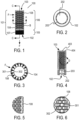
- FIG. 1 shows a polymer melt filter support 100 according to an embodiment of the invention.
- the filter support 100 includes a hollow cylindrical body 101, which resembles the shape of a tube.
- the body 101 includes or is defined by a first end 102, a second end 103 (opposite the first end 102), and a cylinder wall 104 (disposed between the two ends 102 and 103).
- the cylinder wall 104 includes a first end portion 105 proximate or adjacent to the first end 102 and a second end portion 106 proximate or adjacent the second end 103.
- the first end portion 105 includes a screw thread 107 on at least a portion of its outside surface.
- the screw thread 107 is adapted to engage and securely hold the filter support 100 in place with threaded holes in a support plate 1604 (see FIGS. 16 - 19 ).
- the second end portion 106 of the cylinder wall 104 includes a plurality of holes 108.
- the holes 108 extend through the cylinder wall 104 so as to allow a polymer melt from outside of the body 101 to flow inside of the body 101.
- Arrows F show the direction of polymer flow during normal operation.
- the area of (or defined by) the openings 301 of the holes 108 on the outside surface of the cylinder wall 104 is larger than the area of (or defined by) the openings 302 of the corresponding holes on the inside surface of the cylinder wall 104.
- the shape of the openings 301 of the holes 108 on the outside surface of the cylinder wall 104 is non-circular.
- non-circular it is meant any geometric shape except for a perfect circle. Examples of non-circular shapes include triangles, squares, rectangles, ovals, ellipses, quatrefoils, rhombuses, pentagons, hexagons, etc.
- the number of holes in the second end portion 106 may be any number desired.
- the second end portion 106 includes 288 holes arranged in 18 rows of 16 holes per row.
- the second end portion 106 includes 400 holes arranged in 25 rows of 16 holes per row.
- the cylindrical body 101 may be made of any material that can withstand the conditions inside of a filtering apparatus for a polymer melt over an extended period of time. Such conditions include operating temperatures of up to 400°C and operating pressures of up to 7,500 psi (or approximately 50 MPa).
- the cylindrical body 101 is made of 17-4 PH stainless steel, which has been heat treated according to Condition H 900 after the body 101 has been machined. 17-4 PH stainless steel is a precipitation-hardening martensitic stainless steel.
- 17-4 PH stainless steel may contain up to 0.07 wt% of carbon, up to 1 wt% of manganese, up to 0.04 wt% of phosphorus, up to 0.03 wt% of sulfur, and up to 1 wt% of silicon. 17-4 PH is commercially available. It is typically furnished in the annealed condition. This is also called the solution heat treated condition, or Condition A.
- Condition A annealing is conducted by heat treating at approximately 1900°F (1040°C) to 1950°F (1065°C) and cooling to room temperature.
- the material possesses a martensitic structure.
- the cylindrical body 101 is preferably precipitation hardened, after machining, by heat treatment in air at 900°F +/- 10°F (482°C +/- 5°C) for 60 minutes +/- 5 minutes, which is known as Condition H 900.
- the cylindrical body 101 can be of any desired size. In one embodiment, the body 101 has a height of 4.97 inches (12.62 cm). In another embodiment, the body 101 has a height of 6.40 inches (16.256 cm). Preferably, the height of the first end portion 105 is the same regardless of the overall height of the body 101. In one embodiment, the height of the first end portion 105 is 0.88 inches (2.24 cm). In which case, the height of the second end portion 106 can be 3.97 inches (10.08 cm) or 5.4 inches (13.72 cm).
- the ratio of the outside diameter of the cylinder wall 104 to the inside diameter of the cylinder wall 104 ranges from 1.35 to 1.65.
- the cylinder wall 104 has an outside diameter of 1.75 inches (4.445 cm).
- the cylinder wall 104 can have an inside diameter of 1 inch (2.54 cm) to 1.25 inches (3.175 cm).
- the cylinder wall 104 has an inside diameter of 1.125 inches (2.858 cm).
- the first end 102 includes an opening 202 for the polymer melt inside of the body 101 to flow outside of the body 101.
- the inside surface of the first end portion 105 includes a hex fitting 203 for receiving and engaging with a hex wrench (not shown).
- the hex fitting 203 via the use of a hex wrench, enables the filter support 100 to be easily attached to and removed from the support plate 1604 ( FIGS. 16 - 19 ).
- the inside diameter of the cylinder wall 104 is 1.125 inches (2.858 cm)
- the farthest distance between any two opposing points of the hex fitting 203 can be, for example, 1.27 inches (3.226 cm).
- FIG. 3 shows a sectional view of the filter support 100 and, in particular, a sectional view of the second end portion 106 of the cylindrical body 101 along line A-A in FIG. 1 .
- the cylinder wall 104 is represented by the solid areas. The clear areas between the solid areas represent the holes 108 in the cylinder wall 104. From this view, it can be seen that this embodiment of the filter support 100 contains 16 holes in this row (the number of holes per row as well as the number of rows of holes can vary as desired). Moreover, it can be seen that the size or area of the openings 301 of the holes 108 on the outer surface of the cylinder wall 104 is larger than the size or area of the openings 302 of the corresponding holes 108 on the inner surface of the cylinder wall 104.
- the direction of polymer melt flow through the holes 108 is marked by the arrow F. It has been surprisingly discovered that the larger size of the openings 301 on the outer wall surface increases the cross-sectional area for the polymer melt to flow and be filtered, thereby increasing the overall filtration efficiency of any filter that employs the filter support according to the invention.
- FIG. 4 is a sectional view of the filter support 100 from FIG. 1 along line C-C. From this view, the hollowness of the cylindrical body 101 can be seen as well as the opening 202 located at the first end 102 and the opening 403 located at the second end 103. The hex fitting 203 on the inside surface of the first end portion 105 of the cylindrical body 101 can also be seen from this view. FIG. 4 further shows an optional recess, indentation, or notch 404 along the inside surface of the cylindrical wall 104 at the opening 403.
- FIG. 5 is an enlarged view of the second end portion 106 of the cylinder wall 104 along circle D from FIG. 4 . In this view, the rows of holes 108 in the second end portion 106 of the cylinder wall 104 can be seen.
- FIG. 6 is an enlarged view of the second end portion 106 of the cylinder wall 104 around area B from FIG. 1 . From this view, the rows of the holes 108 in the second end portion 106 of the cylinder wall 104 can be seen as well as the details of the holes 108. As noted above, in accordance with the invention, the size or area of the openings 301 of the holes 108 on the outer surface of the cylinder wall 104 is larger than the size or area of the openings 302 of the corresponding holes 108 on the inner surface of the cylinder wall 104.
- the openings 301 and 302 have a non-circular shape. The shapes of the openings may be formed by any known machining technique..
- the openings 301 have shapes resembling an oval or an ellipse.
- oval and ellipse are intended to include shapes that are generally or substantially oval, and generally or substantially elliptic, respectively.
- the terms “generally” and “substantially” mean that the actual shape resembles the named shape more than any other basic geometric shape, such as triangle, square, rectangle, circle, and oval/ellipse.
- the greatest distance between any two opposing points on the perimeter of the oval or elliptic openings 301 in the horizontal direction is greater than the greatest distance between any two opposing points on the perimeter of the oval or elliptic openings 301 in the vertical direction.
- the horizontal diameter (D H ) of the oval or elliptic openings 301 is preferably greater than the vertical diameter (D V ) of the openings 301.
- the ratio of D H / D V can be at least 1.05, at least 1.10, at least 1.15, at least 1.20, at least 1.21, at least 1.22, at least 1.23, or at least 1.24.
- Vertical refers the direction along (or parallel to) the axis of the cylindrical body 101
- horizontal refers to the direction perpendicular to the axis of the cylindrical body 101.
- the oval or elliptic shapes of the openings 301 are formed by first forming circular openings, and then taking scalloped cuts on opposing sides of the circular openings to form the oval- or elliptic-shaped openings.
- the scalloped cuts are made on the left and right sides of the originally circular openings.
- the scalloped cuts give the left and right sides of the openings 301 a generally chamfered profile.
- FIG. 6A is an exploded view of one of the oval/elliptic openings 301 with markings showing D V and D H .
- the shape of the opening 301 is not a perfect oval or ellipse, but to the naked eye, it resembles an oval or ellipse more than other basic geometric shape.
- D H is 0.236 inches (6 mm) and D V is 0.290 inches (7.4 mm), giving rise to an open area of 0.05165 in 2 (33.3 mm 2 ).
- D H is 0.250 inches (6.35 mm) and D V is 0.310 inches (7.87 mm), giving rise to an open area of 0.05859 in 2 (37.8 mm 2 ).
- the shape of the openings 302 of the corresponding holes 108 on the inside surface of the cylinder wall 104 is circular.
- the term "circular,” as used herein, is intended to include generally circular or substantially circular shapes.
- the area or size of the openings (inlets) 301 can be, for example, at least 25%, 50%, or 75% larger than the area or size of the openings (outlets) 302 of the corresponding holes 108.
- each row of holes 108 can be staggered or offset from the rows immediately above and below it.
- each row of holes 108 can be staggered or offset from the next row by the radius of the openings 302.
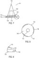
- FIG. 7 shows a cone insert 701 according to the invention.
- the cone insert 701 is adapted to fit inside of the second end opening 403 of the cylindrical body 101, with the apex 702 of the cone insert 701 pointing towards the first end opening 202.
- the cone insert 701 includes a curved lateral surface 703 towards, proximate, or adjacent to its base 704.
- the curved lateral surface 703 serves the function of gradually directing the inflow of polymer melt towards the center of the cylindrical body 101.
- the base 704 has a diameter that is about the same as or slightly smaller than the inside diameter of the cylindrical body 101. Any gap between the diameter of the base 704 and the inside diameter of the cylindrical body 101 should be minimized so as to avoid polymer melt from collecting in or passing through the gap.
- the thickness of the base 704 should be such that the top row 1501 of holes 108 directs the flow of polymer melt towards in the curved lateral surface 703 inside of the cylindrical body 101.
- the curved lateral surface 703 together with the non-curved lateral surface 706 of the cone insert 701 gradually directs the flow of incoming polymer melt towards the direction of the first end opening 202 where the filtered polymer melt eventually exits the filter support 100.
- the cone insert 701 also includes a base plate 705 located on the other side of the base 704, i.e., opposite the side with the curved lateral surface 703.
- the base plate 705 preferably has a diameter that is larger than the inside diameter of the cylindrical body 101, but smaller than the outside diameter of the cylindrical body 101.
- the perimeter portion 707 (see FIG. 8 ) of the base plate 705 is designed to abut or rest against the annular recess 404 in the cylinder wall 104 adjacent the second end opening 403.
- the thickness of the base plate 705 is such that the top surface 708 of the plate 705 is flush or level with the remaining cylinder wall 104 at the second end opening 403.
- the base plate 705 includes one or more recesses 709 around the perimeter of the top surface 708.
- the recesses 709 form reservoirs for solder, weld metal, or some other adhesive material, to join the cone insert 701 with the filter support 100.
- the cone insert 701 can also include a screw hole 710 for securing a cap 1001 onto the insert 701.
- FIGS. 10, 11, and 12 show various views of a filter support cap 1001 according to an embodiment of the invention.
- the cap 1001 is adapted to fit over the second end 103 of the cylindrical body 101 as well as the base plate 705 of the cone insert 701.
- the cap 1001 has a generally frustoconical shape, with a sloping side portion 1002, a curved side portion 1003 below the sloping side portion 1002, and a vertical side portion 1004 below the curved side portion 1003.
- the cap 1001 includes a hole 1005 through its central axis for passing through a screw body (shank).
- the screw threads directly into the screw hole 710 in the cone insert 701 and secures the cap 1001 to the cone insert 701.
- the screw would also secure the cap 1001 to the cylindrical body 101.
- the cap 1001 may include a recessed area 1006 having a generally inverted frustoconical shape in the top portion around the hole 1005 for receiving the conical portion of a flat head or countersunk screw (not shown).
- the bottom portion 1007 of the cap 1001 includes the curved side portion 1003 and the vertical side portion 1004.
- the outside diameter of the curved side portion 1003 and the vertical side portion 1004 is larger than the outside diameter of the cylindrical body 101.
- the interior of the bottom portion 1007 includes a recess 1008 for receiving the second end 103 of the cylindrical body 101.
- the interior of the bottom portion 1007 includes a sloping surface 1009, which slopes away from the outside surface of the cylinder wall 104. The space created between the sloping surface 1009 and the outside surface of the cylinder wall 104 allows for one or more filter elements to be held in place, around the second end portion 103 of the cylindrical body 104.
- the cone insert 701 and the cap 1001 include a hole through their axes for accommodating a tie rod. This embodiment is discussed in more detail below in connection with FIGS. 16 - 19 .
- the present invention provides a polymer melt filter.
- the filter comprises the filter support according to any of the embodiments of the invention and one or more filter elements around the second end portion of the cylindrical body.
- filter elements There are no particular restrictions on the filter elements that may be used with the filter support of the invention, so long as they can be adapted to fit around the second end portion of the cylindrical body.
- filter element media include metal fiber felt, woven wire cloth, wire mesh, screen mesh, metal fiber fleeze, and a perforated metal sheet. Combinations of filter elements may be used.
- the filter elements may be flat or pleated.
- the filter elements may have any desired fineness, such as from 0.5 to 500 ⁇ m, or from 0.5 to 200 ⁇ m.
- FIG. 14A illustrates an embodiment of the second aspect of the invention.
- FIG. 14A shows a filter element 1401 in the form of a sleeve adapted to fit over/around the second end portion 106 of the filter support 100.
- the filter element 1401 has perforations 1402 to let the polymer melt to pass through, but to filter out impurities in the melt, such as solids and/or gels.
- polystyrene poly(acrylonitrile butadiene styrene), ethylene vinyl acetate copolymer, polyethylenes (including HDPE, LDPE, and LLDPE), polyamides (including PA 6 and PA 66), polybutadiene, polyesters (including PET and PBT), polypropylene, and polystyrenes (including HIPS).
- suitable polymers include poly(acrylonitrile butadiene styrene), ethylene vinyl acetate copolymer, polyethylenes (including HDPE, LDPE, and LLDPE), polyamides (including PA 6 and PA 66), polybutadiene, polyesters (including PET and PBT), polypropylene, and polystyrenes (including HIPS).
- a polymer melt first passes through the one or more filter elements to remove any undesired solids and/or gels in the melt.
- the melt then enters the inside of the hollow cylindrical body 101 of the filter support 100 via the holes 108 in the cylinder wall 104.
- the polymer melt then exits the interior of the hollow cylindrical body 101 via the opening 202 in the first end 102 of the body 101.
- the present invention provides a polymer melt filter plate assembly.
- the plate assembly comprises:
- the support plate may have two or more threaded holes into which the filters may be screwed.
- the number of threaded holes can vary, for example, from 2 to 50.
- the support plate includes 24 to 26 holes.
- the threaded holes are typically oriented perpendicular to a planar surface of the support plate.
- the support plate may be made of any material that can withstand the conditions inside of a polymer filtration system over an extended period of time. Such conditions include operating temperatures of up to 400°C and operating pressures of up to 7,500 psi (or approximately 50 MPa).
- the support plate is made of Custom 465 ® stainless steel, which has been heat treated according to Condition H 900 or H 950.
- Custom 465 ® stainless steel generally contains 11.00 to 12.50 wt% of chromium, 10.75 to 11.25 wt% of nickel, 0.75 to 1.25 wt% of molybdenum, 1.50 to 1.80 wt% of titanium, and the balance of iron.
- Custom 465 ® stainless steel may contain up to 0.02 wt% of carbon, up to 0.015 wt% of phosphorus, up to 0.25 wt% of silicon, up to 0.25 wt% of manganese, and up to 0.010 wt% of sulfur.
- Custom 465 ® stainless steel is commercially available. It is typically furnished in the annealed/CT condition. This condition includes heating to 1800°F ⁇ 15°F (982°C ⁇ 8°C), holding at temperature for one hour, and rapidly cooling. The solution annealing is typically followed by refrigerating to -100°F (-73°C), holding at temperature for eight hours, then warming to room temperature (CT). The subzero cooling is usually performed within 24 hours of the solution annealing.
- Condition H 900 refers to heat treatment in air at 900°F +/- 10°F (482°C +/-5°C) for 60 minutes +/- 5 minutes.
- Condition H 950 refers to heat treatment in air at 950°F +/- 10°F (510°C +/- 5°C) for 4 hours +/- 0.25 hours.
- the filter plate assembly includes at least one filter that includes a cone insert and a cap having a hole through their axes for accommodating a tie rod.
- the tie rod has a first end extending through the hole in the cone insert and the cap, and a second end extending through the support plate of the assembly.
- the assembly further includes a cross bar, which is attached to the second end of the tie rod for holding the support plate inside a shaft of an apparatus for filtering a polymer melt. This embodiment of the filter plate assembly is illustrated in FIGS. 16 , 17 , 18 , and 19 .
- the shaft is mounted in the cross-bore of the housing and is movable in the axial direction, so that each connecting channel can be moved between a filtration position in which the inlet channel is connected to the outlet channel through the connecting channel, and a cleaning position in which the connection from the inlet channel to the outlet channel is interrupted and the plate assembly is externally accessible for cleaning.
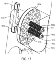
- FIGS. 16 , 17 , 18 , and 19 show a movable shaft 1601 with two connecting channels 1602 and 1603 arranged side-by-side and spanning the thickness of the shaft 1601 for connecting the inlet channel to the outlet channel.
- Connecting channel 1603 is provided with a filter plate assembly according to the invention.
- the plate assembly includes a support plate 1604, two filter supports 1605, two tie rods 1606, and a cross bar 1607.
- the support plate 1604 has a planar supporting surface 1608 on one side, a convex surface 1609 on the other side, and a plurality of threaded holes 1610.
- the filter supports 1605 are attached to two adjacent, centrally located threaded holes 1610.
- Each of the filter supports 1605 is provided with a cone insert 1619 and a cap 1611.
- the cone insert 1619 and cap 1611 have a hole through their center for accommodating the tie rod 1606.
- the inside surface of the through-hole in the cone insert 1619 may be tapered to help guide the tie rod 1606 through the cone insert 1619. The larger end of the taper is towards the apex of the cone insert 1619.
- the tie rod 1606 may be threaded at both ends. One end of the tie rod 1606 engages with a nut 1612. A washer 1613 may be placed between the nut 1612 and the cap 1611. The other end of the tie rod 1606 is threaded into a threaded hole 1614 in the cross bar 1607. The body of the tie rod 1606 passes through the center of the filter support 1605.
- the connecting channel 1603 in the shaft 1601 has an inlet 1615 and an outlet 1616.
- the connecting channel 1603 also includes a ledge or projection 1618 running radially and protruding into the channel 1603, serving to support the support plate 1604.
- the cross bar 1607 has sufficient length to span the width of the outlet 1616.
- the shaft 1601 includes recesses 1617 adjacent the outlet 1616 (opening on downstream side of the connecting channel 1603) for accommodating the cross bar 1607.
- the tie rod 1606, together with the cross bar 1607 and the nut 1612, surely holds the support plate 1604 against the ledge 1618 inside of the shaft 1601. This mechanism for holding the support plate 1604 in place has a number of advantages, including minimizing or preventing the support plate from substantially moving (e.g., vibrating) during filtration, which can cause premature cracking or breakage.
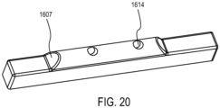
- FIG. 20 shows an exemplary shape of the cross bar 1607 with two threaded holes 1614 for engaging with a threaded end of the tie rod 1606.
- tie rods 1606 are depicted in FIGS. 16-19 , one or more than two may be used.
- the cap 1001, cap insert 701, tie rods 1606, and cross bar 1607 may be made of any suitable material that can withstand the operating conditions.
- An example of such material is 17-4 PH stainless steel which has been heat treated according to Condition H 900.
- the present invention provides a process for filtering a polymer melt.
- the process comprises passing a polymer melt through the one or more filter elements around the second end portion of the cylindrical body of the polymer melt filter according to the invention, and withdrawing a filtered polymer melt from the inside of the cylindrical body.
Landscapes
- Engineering & Computer Science (AREA)
- Mechanical Engineering (AREA)
- Chemical & Material Sciences (AREA)
- Chemical Kinetics & Catalysis (AREA)
- Manufacturing & Machinery (AREA)
- Materials Engineering (AREA)
- Metallurgy (AREA)
- Organic Chemistry (AREA)
- Extrusion Moulding Of Plastics Or The Like (AREA)
- Filtration Of Liquid (AREA)
- Filtering Materials (AREA)
Description
- The invention generally relates to filters for polymer melts.
- Thermoplastic polymers in the molten state are often filtered to remove impurities, such as solids and/or gels, before they are passed to a mold cavity or through a die plate. Examples of polymer filtering devices are shown in
US 4,701,118 ,US 5,004,414 ,US 6,641,728 ,DE 20 2016 105013 U1 ,JP H10 217281 A DD 211 312 A1 EP 2 045 437 A2 andUS 2010/300986 A1 . - The filter portion of these devices typically includes a foraminous supporting plate and a plurality of filters resembling sticks or candles. The filters themselves are composed of tubular support structures with one or more filter media in the form of a sleeve wrapped around the tubular support structures.
- Both the foraminous supporting plates and the tubular support structures available in the market today, however, suffer from a number of disadvantages. For example, the design of the tubular support structures is not very efficient for filtering or for replacement. Moreover, the foraminous supporting plates and the tubular support structures are susceptible to cracking and breakage under normal use.
- Thus, there is a need in the art for improved foraminous supporting plates and tubular support structures for filtering polymer melts.
- The present invention addresses this need as well as others, which will become apparent from the following description and the appended claims.
- The invention is as set forth in the appended claims.
- Briefly, in a first aspect, the present invention provides a polymer melt filter support. The filter support comprises:
- a hollow cylindrical body defined by a first end, a second end, and a cylinder wall having a first end portion and a second end portion;
- a screw thread on the outside surface of the first end portion; and
- a plurality of holes in the cylinder wall at the second end portion,
- wherein the holes allow for a polymer melt outside of the cylindrical body to flow inside of the cylindrical body,
- wherein the first end comprises an opening for the polymer melt inside of the cylindrical body to flow outside of the cylindrical body,
- wherein the area of the openings of the holes on the outside surface of the cylinder wall is larger than the area of the openings of the corresponding holes on the inside surface of the cylinder wall, and
- wherein the shape of the openings of the holes on the outside surface is non-circular, and which further comprises an opening at the second end, a cone insert adapted to fit inside of the second end opening, and a cap for securing one or more filter elements around the second end portion of the cylindrical body, wherein the cone insert comprises a curved lateral surface towards its base, and
wherein the cone insert comprises a base plate, - wherein the perimeter of the base plate comprises one or more recesses, and
- wherein the recesses and an inner surface of the cylindrical body define a reservoir for holding solder or weld metal for joining the cone insert to the cylindrical body.
- In a second aspect, the present invention provides a polymer melt filter. The filter comprises a filter support according to invention and one or more filter elements around the second end portion of the cylindrical body.
- In a third aspect, the present invention provides a polymer melt filter plate assembly. The plate assembly comprises:
- (a) a support plate comprising a plurality of threaded holes; and
- (b) at least one filter according to the invention, which is screwed into at least one of the threaded holes via the screw thread on the outside surface of the first end portion of the cylindrical body.
- In a fourth aspect, the present invention provides a process for filtering a polymer melt. The process comprises passing a polymer melt through the one or more filter elements around the second end portion of the cylindrical body of the polymer melt filter according to the invention, and withdrawing a filtered polymer melt from the inside of the cylindrical body.
-
-
FIG. 1 is an elevation view of a polymer melt filter support according to the invention; -
FIG. 2 is a plan view of the bottom end of a polymer melt filter support according to the invention; -
FIG. 3 is a sectional view of the polymer melt filter support along line A-A inFIG. 1 ; -
FIG. 4 is a sectional view of the polymer melt filter support along line C-C inFIG. 1 ; -
FIG. 5 is an enlarged view of cutout D from the sectional view inFIG. 4 ; -
FIG. 6 is an enlarged view of area B from the cylindrical wall of the second end portion inFIG. 1 ; -
FIG. 6A is an enlarged view of a hole on the outside surface of the cylindrical wall of the second end portion inFIG. 1 ; -
FIG. 7 is an elevation view of a cone insert according to the invention; -
FIG. 8 is a plan view of the top of the cone insert inFIG. 7 ; -
FIG. 9 is an enlarged view of cutout E from the cone insert inFIG. 7 ; -
FIG. 10 is an elevation view of a filter support cap according to the invention; -
FIG. 11 is a plan view of the cap shown inFIG. 10 ; -
FIG. 12 is a plan view from the bottom of the cap shown inFIG. 10 .; -
FIG. 13 is an enlarged view of cutout G from the cap shown inFIG. 10 ; -
FIG. 14 is a plan view of the polymer filter support shown inFIG. 1 fitted with a cone insert and a cap; -
FIG. 14A is a plan view of the polymer filter support shown inFIG 14 fitted with a filter sleeve over the second end portion. -
FIG. 15 is a sectional view of the polymer filter support along line A-A inFIG. 14 ; -
FIG. 16 is a perspective (see-through) view of a shaft from a filtering apparatus with a polymer melt filter plate assembly according to the invention in a connecting channel; -
FIG. 17 is a detailed, perspective view of the inlet of the connecting channel with the filter plate assembly depicted inFIG. 16 ; -
FIG. 18 is a sectional view of the filter plate assembly inside of the shaft depicted inFIG. 16 ; -
FIG. 19 is a detailed, perspective view of the outlet of the connecting channel with the filter plate assembly depicted inFIG. 16 ; -
FIG. 20 is a perspective view of a cross bar according to the invention, which spans the width of the outlet of the connecting channel depicted inFIG. 19 . - In a first aspect, the present invention provides a polymer melt filter support. The filter support comprises:
- a hollow cylindrical body defined by a first end, a second end, and a cylinder wall having a first end portion and a second end portion;
- a screw thread on the outside surface of the first end portion; and
- a plurality of holes in the cylinder wall at the second end portion,
- wherein the holes allow for a polymer melt outside of the cylindrical body to flow inside of the cylindrical body,
- wherein the first end comprises an opening for the polymer melt inside of the cylindrical body to flow outside of the cylindrical body,
- wherein the area of the openings of the holes on the outside surface of the cylinder wall is larger than the area of the openings of the corresponding holes on the inside surface of the cylinder wall, and
- wherein the shape of the openings of the holes on the outside surface is non-circular, and which further comprises an opening at the second end, a cone insert adapted to fit inside of the second end opening, and a cap for securing one or more filter elements around the second end portion of the cylindrical body, wherein the cone insert comprises a curved lateral surface towards its base, and
wherein the cone insert comprises a base plate, - wherein the perimeter of the base plate comprises one or more recesses, and
- wherein the recesses and an inner surface of the cylindrical body define a reservoir for holding solder or weld metal for joining the cone insert to the cylindrical body.
- In another embodiment, the polymer melt filter support further comprises:
a hex fitting on the inside surface of the first end portion for receiving a hex wrench. -
FIG. 1 shows a polymermelt filter support 100 according to an embodiment of the invention. Thefilter support 100 includes a hollowcylindrical body 101, which resembles the shape of a tube. Thebody 101 includes or is defined by afirst end 102, a second end 103 (opposite the first end 102), and a cylinder wall 104 (disposed between the two ends 102 and 103). Thecylinder wall 104 includes afirst end portion 105 proximate or adjacent to thefirst end 102 and asecond end portion 106 proximate or adjacent thesecond end 103. Thefirst end portion 105 includes ascrew thread 107 on at least a portion of its outside surface. Thescrew thread 107 is adapted to engage and securely hold thefilter support 100 in place with threaded holes in a support plate 1604 (seeFIGS. 16 - 19 ). - The
second end portion 106 of thecylinder wall 104 includes a plurality ofholes 108. Theholes 108 extend through thecylinder wall 104 so as to allow a polymer melt from outside of thebody 101 to flow inside of thebody 101. Arrows F show the direction of polymer flow during normal operation. Furthermore, as will be explained in greater detail below in connection withFIG. 3 and FIG. 6 , the area of (or defined by) theopenings 301 of theholes 108 on the outside surface of thecylinder wall 104 is larger than the area of (or defined by) theopenings 302 of the corresponding holes on the inside surface of thecylinder wall 104. Additionally, the shape of theopenings 301 of theholes 108 on the outside surface of thecylinder wall 104 is non-circular. By "non-circular," it is meant any geometric shape except for a perfect circle. Examples of non-circular shapes include triangles, squares, rectangles, ovals, ellipses, quatrefoils, rhombuses, pentagons, hexagons, etc. - The number of holes in the
second end portion 106 may be any number desired. In one embodiment, thesecond end portion 106 includes 288 holes arranged in 18 rows of 16 holes per row. In another embodiment, thesecond end portion 106 includes 400 holes arranged in 25 rows of 16 holes per row. - The
cylindrical body 101 may be made of any material that can withstand the conditions inside of a filtering apparatus for a polymer melt over an extended period of time. Such conditions include operating temperatures of up to 400°C and operating pressures of up to 7,500 psi (or approximately 50 MPa). Preferably, thecylindrical body 101 is made of 17-4 PH stainless steel, which has been heat treated according to Condition H 900 after thebody 101 has been machined. 17-4 PH stainless steel is a precipitation-hardening martensitic stainless steel. It generally contains 15 - 17.5 wt% of chromium, 3 - 5 wt% of copper, 3 - 5 wt% of nickel, 0.15 - 0.45 wt% of niobium plus tantalum, and the balance of iron. 17-4 PH stainless steel may contain up to 0.07 wt% of carbon, up to 1 wt% of manganese, up to 0.04 wt% of phosphorus, up to 0.03 wt% of sulfur, and up to 1 wt% of silicon. 17-4 PH is commercially available. It is typically furnished in the annealed condition. This is also called the solution heat treated condition, or Condition A. According to Condition A, annealing is conducted by heat treating at approximately 1900°F (1040°C) to 1950°F (1065°C) and cooling to room temperature. In this condition, the material possesses a martensitic structure. To further increase its strength, thecylindrical body 101 is preferably precipitation hardened, after machining, by heat treatment in air at 900°F +/- 10°F (482°C +/- 5°C) for 60 minutes +/- 5 minutes, which is known as Condition H 900. - The
cylindrical body 101 can be of any desired size. In one embodiment, thebody 101 has a height of 4.97 inches (12.62 cm). In another embodiment, thebody 101 has a height of 6.40 inches (16.256 cm). Preferably, the height of thefirst end portion 105 is the same regardless of the overall height of thebody 101. In one embodiment, the height of thefirst end portion 105 is 0.88 inches (2.24 cm). In which case, the height of thesecond end portion 106 can be 3.97 inches (10.08 cm) or 5.4 inches (13.72 cm). - Preferably, the ratio of the outside diameter of the
cylinder wall 104 to the inside diameter of thecylinder wall 104 ranges from 1.35 to 1.65. In one embodiment, thecylinder wall 104 has an outside diameter of 1.75 inches (4.445 cm). In which case, thecylinder wall 104 can have an inside diameter of 1 inch (2.54 cm) to 1.25 inches (3.175 cm). Preferably, thecylinder wall 104 has an inside diameter of 1.125 inches (2.858 cm). - As seen from
FIGS. 2, 4, and 5 , thefirst end 102 includes anopening 202 for the polymer melt inside of thebody 101 to flow outside of thebody 101. In one embodiment, the inside surface of thefirst end portion 105 includes a hex fitting 203 for receiving and engaging with a hex wrench (not shown). The hex fitting 203, via the use of a hex wrench, enables thefilter support 100 to be easily attached to and removed from the support plate 1604 (FIGS. 16 - 19 ). In the case the inside diameter of thecylinder wall 104 is 1.125 inches (2.858 cm), the farthest distance between any two opposing points of the hex fitting 203 can be, for example, 1.27 inches (3.226 cm). -
FIG. 3 shows a sectional view of thefilter support 100 and, in particular, a sectional view of thesecond end portion 106 of thecylindrical body 101 along line A-A inFIG. 1 . Thecylinder wall 104 is represented by the solid areas. The clear areas between the solid areas represent theholes 108 in thecylinder wall 104. From this view, it can be seen that this embodiment of thefilter support 100 contains 16 holes in this row (the number of holes per row as well as the number of rows of holes can vary as desired). Moreover, it can be seen that the size or area of theopenings 301 of theholes 108 on the outer surface of thecylinder wall 104 is larger than the size or area of theopenings 302 of the correspondingholes 108 on the inner surface of thecylinder wall 104. The direction of polymer melt flow through theholes 108 is marked by the arrow F. It has been surprisingly discovered that the larger size of theopenings 301 on the outer wall surface increases the cross-sectional area for the polymer melt to flow and be filtered, thereby increasing the overall filtration efficiency of any filter that employs the filter support according to the invention. -
FIG. 4 is a sectional view of thefilter support 100 fromFIG. 1 along line C-C. From this view, the hollowness of thecylindrical body 101 can be seen as well as theopening 202 located at thefirst end 102 and theopening 403 located at thesecond end 103. The hex fitting 203 on the inside surface of thefirst end portion 105 of thecylindrical body 101 can also be seen from this view.FIG. 4 further shows an optional recess, indentation, or notch 404 along the inside surface of thecylindrical wall 104 at theopening 403. -
FIG. 5 is an enlarged view of thesecond end portion 106 of thecylinder wall 104 along circle D fromFIG. 4 . In this view, the rows ofholes 108 in thesecond end portion 106 of thecylinder wall 104 can be seen. -
FIG. 6 is an enlarged view of thesecond end portion 106 of thecylinder wall 104 around area B fromFIG. 1 . From this view, the rows of theholes 108 in thesecond end portion 106 of thecylinder wall 104 can be seen as well as the details of theholes 108. As noted above, in accordance with the invention, the size or area of theopenings 301 of theholes 108 on the outer surface of thecylinder wall 104 is larger than the size or area of theopenings 302 of the correspondingholes 108 on the inner surface of thecylinder wall 104. Theopenings openings 301 have shapes resembling an oval or an ellipse. As used herein, the terms "oval" and "ellipse" (and variations thereof) are intended to include shapes that are generally or substantially oval, and generally or substantially elliptic, respectively. When modifying geometric shapes, the terms "generally" and "substantially" mean that the actual shape resembles the named shape more than any other basic geometric shape, such as triangle, square, rectangle, circle, and oval/ellipse. - Preferably, the greatest distance between any two opposing points on the perimeter of the oval or
elliptic openings 301 in the horizontal direction is greater than the greatest distance between any two opposing points on the perimeter of the oval orelliptic openings 301 in the vertical direction. In other words, the horizontal diameter (DH) of the oval orelliptic openings 301 is preferably greater than the vertical diameter (DV) of theopenings 301. The ratio of DH / DV can be at least 1.05, at least 1.10, at least 1.15, at least 1.20, at least 1.21, at least 1.22, at least 1.23, or at least 1.24. Vertical refers the direction along (or parallel to) the axis of thecylindrical body 101, and horizontal refers to the direction perpendicular to the axis of thecylindrical body 101. - In one embodiment, the oval or elliptic shapes of the
openings 301 are formed by first forming circular openings, and then taking scalloped cuts on opposing sides of the circular openings to form the oval- or elliptic-shaped openings. In the case ofFIG. 6 , the scalloped cuts are made on the left and right sides of the originally circular openings. The scalloped cuts give the left and right sides of the openings 301 a generally chamfered profile. -
FIG. 6A is an exploded view of one of the oval/elliptic openings 301 with markings showing DV and DH. As seen fromFIG. 6A , the shape of theopening 301 is not a perfect oval or ellipse, but to the naked eye, it resembles an oval or ellipse more than other basic geometric shape. In one embodiment, DH is 0.236 inches (6 mm) and DV is 0.290 inches (7.4 mm), giving rise to an open area of 0.05165 in2 (33.3 mm2). In another embodiment, DH is 0.250 inches (6.35 mm) and DV is 0.310 inches (7.87 mm), giving rise to an open area of 0.05859 in2 (37.8 mm2). - Preferably, the shape of the
openings 302 of the correspondingholes 108 on the inside surface of thecylinder wall 104 is circular. The term "circular," as used herein, is intended to include generally circular or substantially circular shapes. - The area or size of the openings (inlets) 301 can be, for example, at least 25%, 50%, or 75% larger than the area or size of the openings (outlets) 302 of the corresponding holes 108.
- Also, as shown in
FIG. 6 , to maximize the size and number of theholes 108, each row ofholes 108 can be staggered or offset from the rows immediately above and below it. For example, each row ofholes 108 can be staggered or offset from the next row by the radius of theopenings 302. -
FIG. 7 shows acone insert 701 according to the invention. As seen fromFIG. 15 , thecone insert 701 is adapted to fit inside of the second end opening 403 of thecylindrical body 101, with the apex 702 of thecone insert 701 pointing towards thefirst end opening 202. As seen fromFIGS. 7, 9 , and15 , thecone insert 701 includes a curvedlateral surface 703 towards, proximate, or adjacent to itsbase 704. The curvedlateral surface 703 serves the function of gradually directing the inflow of polymer melt towards the center of thecylindrical body 101. - The
base 704 has a diameter that is about the same as or slightly smaller than the inside diameter of thecylindrical body 101. Any gap between the diameter of thebase 704 and the inside diameter of thecylindrical body 101 should be minimized so as to avoid polymer melt from collecting in or passing through the gap. The thickness of the base 704 should be such that thetop row 1501 ofholes 108 directs the flow of polymer melt towards in the curvedlateral surface 703 inside of thecylindrical body 101. The curvedlateral surface 703 together with the non-curvedlateral surface 706 of thecone insert 701 gradually directs the flow of incoming polymer melt towards the direction of the first end opening 202 where the filtered polymer melt eventually exits thefilter support 100. - The
cone insert 701 also includes abase plate 705 located on the other side of thebase 704, i.e., opposite the side with the curvedlateral surface 703. Thebase plate 705 preferably has a diameter that is larger than the inside diameter of thecylindrical body 101, but smaller than the outside diameter of thecylindrical body 101. The perimeter portion 707 (seeFIG. 8 ) of thebase plate 705 is designed to abut or rest against theannular recess 404 in thecylinder wall 104 adjacent thesecond end opening 403. Preferably, the thickness of thebase plate 705 is such that thetop surface 708 of theplate 705 is flush or level with the remainingcylinder wall 104 at thesecond end opening 403. - As seen from
FIGS. 7, 8, and 9 , thebase plate 705 includes one ormore recesses 709 around the perimeter of thetop surface 708. Therecesses 709 form reservoirs for solder, weld metal, or some other adhesive material, to join thecone insert 701 with thefilter support 100. - As seen from
FIGS. 7, 8 , and15 , thecone insert 701 can also include ascrew hole 710 for securing acap 1001 onto theinsert 701. -
FIGS. 10, 11, and 12 show various views of afilter support cap 1001 according to an embodiment of the invention. As seen fromFIGS. 14, 14A , and15 , thecap 1001 is adapted to fit over thesecond end 103 of thecylindrical body 101 as well as thebase plate 705 of thecone insert 701. As seen fromFIGS. 10 and 13 , thecap 1001 has a generally frustoconical shape, with asloping side portion 1002, acurved side portion 1003 below the slopingside portion 1002, and avertical side portion 1004 below thecurved side portion 1003. Thecap 1001 includes ahole 1005 through its central axis for passing through a screw body (shank). The screw (not shown) threads directly into thescrew hole 710 in thecone insert 701 and secures thecap 1001 to thecone insert 701. When thecone insert 701 has been welded or otherwise secured onto thecylindrical body 101, the screw would also secure thecap 1001 to thecylindrical body 101. Thecap 1001 may include a recessedarea 1006 having a generally inverted frustoconical shape in the top portion around thehole 1005 for receiving the conical portion of a flat head or countersunk screw (not shown). - As seen from
FIGS. 10 and 13 , thebottom portion 1007 of thecap 1001 includes thecurved side portion 1003 and thevertical side portion 1004. The outside diameter of thecurved side portion 1003 and thevertical side portion 1004 is larger than the outside diameter of thecylindrical body 101. The interior of thebottom portion 1007 includes arecess 1008 for receiving thesecond end 103 of thecylindrical body 101. The interior of thebottom portion 1007 includes asloping surface 1009, which slopes away from the outside surface of thecylinder wall 104. The space created between thesloping surface 1009 and the outside surface of thecylinder wall 104 allows for one or more filter elements to be held in place, around thesecond end portion 103 of thecylindrical body 104. - In another embodiment of the invention, the
cone insert 701 and thecap 1001 include a hole through their axes for accommodating a tie rod. This embodiment is discussed in more detail below in connection withFIGS. 16 - 19 . - In a second aspect, the present invention provides a polymer melt filter. The filter comprises the filter support according to any of the embodiments of the invention and one or more filter elements around the second end portion of the cylindrical body. There are no particular restrictions on the filter elements that may be used with the filter support of the invention, so long as they can be adapted to fit around the second end portion of the cylindrical body. Examples of filter element media include metal fiber felt, woven wire cloth, wire mesh, screen mesh, metal fiber fleeze, and a perforated metal sheet. Combinations of filter elements may be used. The filter elements may be flat or pleated. The filter elements may have any desired fineness, such as from 0.5 to 500 µm, or from 0.5 to 200 µm.
-
FIG. 14A illustrates an embodiment of the second aspect of the invention.FIG. 14A shows afilter element 1401 in the form of a sleeve adapted to fit over/around thesecond end portion 106 of thefilter support 100. Thefilter element 1401 hasperforations 1402 to let the polymer melt to pass through, but to filter out impurities in the melt, such as solids and/or gels. - The types of polymer melts that can be filtered using the filter according to the invention are not particularly limiting. Examples of suitable polymers include poly(acrylonitrile butadiene styrene), ethylene vinyl acetate copolymer, polyethylenes (including HDPE, LDPE, and LLDPE), polyamides (including PA 6 and PA 66), polybutadiene, polyesters (including PET and PBT), polypropylene, and polystyrenes (including HIPS).
- In use, a polymer melt first passes through the one or more filter elements to remove any undesired solids and/or gels in the melt. The melt then enters the inside of the hollow
cylindrical body 101 of thefilter support 100 via theholes 108 in thecylinder wall 104. The polymer melt then exits the interior of the hollowcylindrical body 101 via theopening 202 in thefirst end 102 of thebody 101. - In a third aspect, the present invention provides a polymer melt filter plate assembly. The plate assembly comprises:
- (a) a support plate comprising a plurality of threaded holes; and
- (b) at least one filter according to the invention, which is screwed into at least one of the threaded holes via the screw thread on the outside surface of the first end portion of the cylindrical body.
- The support plate may have two or more threaded holes into which the filters may be screwed. The number of threaded holes can vary, for example, from 2 to 50. In one embodiment, the support plate includes 24 to 26 holes. The threaded holes are typically oriented perpendicular to a planar surface of the support plate.
- The support plate may be made of any material that can withstand the conditions inside of a polymer filtration system over an extended period of time. Such conditions include operating temperatures of up to 400°C and operating pressures of up to 7,500 psi (or approximately 50 MPa). In one embodiment, the support plate is made of Custom 465® stainless steel, which has been heat treated according to Condition H 900 or H 950. Custom 465® stainless steel generally contains 11.00 to 12.50 wt% of chromium, 10.75 to 11.25 wt% of nickel, 0.75 to 1.25 wt% of molybdenum, 1.50 to 1.80 wt% of titanium, and the balance of iron. Custom 465® stainless steel may contain up to 0.02 wt% of carbon, up to 0.015 wt% of phosphorus, up to 0.25 wt% of silicon, up to 0.25 wt% of manganese, and up to 0.010 wt% of sulfur. Custom 465® stainless steel is commercially available. It is typically furnished in the annealed/CT condition. This condition includes heating to 1800°F ± 15°F (982°C ± 8°C), holding at temperature for one hour, and rapidly cooling. The solution annealing is typically followed by refrigerating to -100°F (-73°C), holding at temperature for eight hours, then warming to room temperature (CT). The subzero cooling is usually performed within 24 hours of the solution annealing.
- Condition H 900 refers to heat treatment in air at 900°F +/- 10°F (482°C +/-5°C) for 60 minutes +/- 5 minutes. Condition H 950 refers to heat treatment in air at 950°F +/- 10°F (510°C +/- 5°C) for 4 hours +/- 0.25 hours.
- In one embodiment, the filter plate assembly includes at least one filter that includes a cone insert and a cap having a hole through their axes for accommodating a tie rod. The tie rod has a first end extending through the hole in the cone insert and the cap, and a second end extending through the support plate of the assembly. The assembly further includes a cross bar, which is attached to the second end of the tie rod for holding the support plate inside a shaft of an apparatus for filtering a polymer melt. This embodiment of the filter plate assembly is illustrated in
FIGS. 16 ,17 ,18 , and19 . - By way of background, a polymer melt filtering apparatus typically includes (a) a housing comprising an inlet channel for receiving a flow of polymer melt, a cross-bore for accommodating a movable shaft, and an outlet channel for discharging a filtered polymer melt; and (b) a movable shaft comprising a plurality of connecting channels arranged side-by-side and spanning the thickness of the shaft for connecting the inlet channel to the outlet channel. Each connecting channel includes a filter support plate assembly, which is situated across the flow direction of the polymer melt, for filtering the polymer melt. The shaft is mounted in the cross-bore of the housing and is movable in the axial direction, so that each connecting channel can be moved between a filtration position in which the inlet channel is connected to the outlet channel through the connecting channel, and a cleaning position in which the connection from the inlet channel to the outlet channel is interrupted and the plate assembly is externally accessible for cleaning.
-
FIGS. 16 ,17 ,18 , and19 show amovable shaft 1601 with two connectingchannels 1602 and 1603 arranged side-by-side and spanning the thickness of theshaft 1601 for connecting the inlet channel to the outlet channel. Connectingchannel 1603 is provided with a filter plate assembly according to the invention. In the embodiment shown, the plate assembly includes asupport plate 1604, two filter supports 1605, twotie rods 1606, and across bar 1607. - The
support plate 1604 has a planar supportingsurface 1608 on one side, aconvex surface 1609 on the other side, and a plurality of threadedholes 1610. In the embodiment shown, the filter supports 1605 are attached to two adjacent, centrally located threadedholes 1610. Each of the filter supports 1605 is provided with acone insert 1619 and acap 1611. Thecone insert 1619 andcap 1611 have a hole through their center for accommodating thetie rod 1606. The inside surface of the through-hole in thecone insert 1619 may be tapered to help guide thetie rod 1606 through thecone insert 1619. The larger end of the taper is towards the apex of thecone insert 1619. - The
tie rod 1606 may be threaded at both ends. One end of thetie rod 1606 engages with anut 1612. Awasher 1613 may be placed between thenut 1612 and thecap 1611. The other end of thetie rod 1606 is threaded into a threadedhole 1614 in thecross bar 1607. The body of thetie rod 1606 passes through the center of thefilter support 1605. - The connecting
channel 1603 in theshaft 1601 has aninlet 1615 and anoutlet 1616. The connectingchannel 1603 also includes a ledge orprojection 1618 running radially and protruding into thechannel 1603, serving to support thesupport plate 1604. Thecross bar 1607 has sufficient length to span the width of theoutlet 1616. Theshaft 1601 includesrecesses 1617 adjacent the outlet 1616 (opening on downstream side of the connecting channel 1603) for accommodating thecross bar 1607. Thetie rod 1606, together with thecross bar 1607 and thenut 1612, surely holds thesupport plate 1604 against theledge 1618 inside of theshaft 1601. This mechanism for holding thesupport plate 1604 in place has a number of advantages, including minimizing or preventing the support plate from substantially moving (e.g., vibrating) during filtration, which can cause premature cracking or breakage. -
FIG. 20 shows an exemplary shape of thecross bar 1607 with two threadedholes 1614 for engaging with a threaded end of thetie rod 1606. - Although two
tie rods 1606 are depicted inFIGS. 16-19 , one or more than two may be used. - The
cap 1001,cap insert 701,tie rods 1606, andcross bar 1607 may be made of any suitable material that can withstand the operating conditions. An example of such material is 17-4 PH stainless steel which has been heat treated according to Condition H 900. - In a fourth aspect, the present invention provides a process for filtering a polymer melt. The process comprises passing a polymer melt through the one or more filter elements around the second end portion of the cylindrical body of the polymer melt filter according to the invention, and withdrawing a filtered polymer melt from the inside of the cylindrical body.
- As used herein, the indefinite articles "a" and "an" mean one or more, unless the context clearly suggests otherwise. Similarly, the singular form of nouns includes their plural form, and vice versa, unless the context clearly suggests otherwise.
Claims (13)
- A polymer melt filter support (100) comprising:a hollow cylindrical body (101) defined by a first end (102), a second end (103), and a cylinder wall (104) having a first end portion (105) and a second end portion (106);a screw thread (107) on the outside surface of the first end portion (105); anda plurality of holes (108) in the cylinder wall (104) at the second end portion (106),wherein the holes (108) allow for a polymer melt outside of the cylindrical body (101) to flow inside of the cylindrical body (101),wherein the first end (102) comprises an opening (202) for the polymer melt inside of the cylindrical body (101) to flow outside of the cylindrical body (101),wherein the area of the openings (301) of the holes (108) on the outside surface of the cylinder wall (104) is larger than the area of the openings (108) of the corresponding holes (108) on the inside surface of the cylinder wall (104), andwherein the shape of the openings (301) of the holes (108) on the outside surface is non-circular, and which further comprises an opening (403) at the second end (103), a cone insert (701) adapted to fit inside of the second end opening (403), and a cap (1001) for securing one or more filter elements around the second end portion (106) of the cylindrical body (101), wherein the cone insert (701) comprises a curved lateral surface (703) towards its base (704), and
wherein the cone insert (701) comprises a base plate (705),characterised in that the perimeter of the base plate (705) comprises one or more recesses (709),wherein the recesses (709) and an inner surface of the cylindrical body (101) define a reservoir for holding solder or weld metal for joining the cone insert (701) to the cylindrical body (101). - The filter support according to claim 1, wherein the cylindrical body (101) is made of 17-4 PH stainless steel which has been heat treated in air at 482 °C ± 5 °C for 60 minutes ± 5 minutes.
- The filter support according to claim 1, wherein the ratio of the outside diameter of the cylinder wall (104) to the inside diameter of the cylinder wall (104) ranges from 1.35 to 1.65.
- The filter support according to claim 1, which further comprises a hex fitting (203) on the inside surface of the first end portion (105) of the cylindrical body (101) for receiving a hex wrench.
- The filter support according to claim 1, wherein the cone insert (701, 1619) and the cap (1001, 1611) have a hole through their axes for accommodating a tie rod (1606).
- The filter support according to claim 1, wherein the area of the openings (301) of the holes (108) on the outside surface of the cylindrical body wall (104) is at least 25%, at least 50 %, or at least 75 % larger than the area of the openings (302) of the corresponding holes (108) on the inside surface of the cylindrical body wall (104).
- The filter support according to claim 1, wherein the shape of the openings (301) of the holes (108) on the outside surface of the cylinder wall (104) is oval or elliptic, and the shape of the openings (302) of the corresponding holes (108) on the inside surface of the cylinder wall (104) is circular.
- A polymer melt filter comprising the filter support (100) according to any one of claims 1 to 7 and one or more filter elements around the second end portion of the cylindrical body.
- The filter according to claim 8, wherein the filter elements (1401) comprise metal fiber felt, woven wire cloth, wire mesh, or a perforated metal sheet; or wherein the filter elements (1401) are flat or pleated.
- A polymer melt filter plate assembly comprising:(a) a support plate (1604) comprising a plurality of threaded holes (1610); and(b) at least one filter according to claim 8, which is screwed into at least one of the threaded holes (1610) via the screw thread (107) on the outside surface of the first end portion (105) of the cylindrical body (104).
- A polymer melt filter plate assembly comprising:(a) a support plate (1604) comprising a plurality of threaded holes (1610);(b) at least one filter comprising the filter support according to claim 5, which comprises one or more filter elements around the second end portion of the cylindrical body and is screwed into at least one of the threaded holes (1610) via the screw thread on the outside surface of the first end portion (105);(c) a tie rod (1606) with a first end extending through the hole in the cone insert (1619) and the cap (1611), and a second end extending through the support plate (1604); and(d) a cross bar (1607) which is attached to the second end of the tie rod (1606) for holding the support plate (1604) inside a shaft (1601) of an apparatus for filtering a polymer melt.
- The plate assembly according to claim 10 or 11, wherein the support plate (1604) is made of a stainless steel comprising 11.00 to 12.50 wt% of chromium, 10.75 to 11.25 wt% of nickel, 0.75 to 1.25 wt% of molybdenum, 1.50 to 1.80 wt% of titanium, and the balance of iron; and wherein the stainless steel has been heat treated in air at 482 °C ± 5 °C for 60 minutes ± 5 minutes or at 510 °C ± 5 °C for 4 hours ± 0.25 hours.
- A process for filtering a polymer melt, the process comprising passing a polymer melt through the one or more filter elements (1401) around the second end portion (106) of the cylindrical body (104) of the polymer melt filter according to claim 8, and withdrawing a filtered polymer melt from the inside of the cylindrical body (104).
Priority Applications (1)
| Application Number | Priority Date | Filing Date | Title |
|---|---|---|---|
| EP25166435.5A EP4552823A3 (en) | 2016-10-31 | 2017-10-25 | Candle filter support and plate assembly for polymer melts |
Applications Claiming Priority (2)
| Application Number | Priority Date | Filing Date | Title |
|---|---|---|---|
| US15/338,792 US10188968B2 (en) | 2016-10-31 | 2016-10-31 | Candle filter support and plate assembly for polymer melts |
| PCT/US2017/058271 WO2018081258A1 (en) | 2016-10-31 | 2017-10-25 | Candle filter support and plate assembly for polymer melts |
Related Child Applications (2)
| Application Number | Title | Priority Date | Filing Date |
|---|---|---|---|
| EP25166435.5A Division EP4552823A3 (en) | 2016-10-31 | 2017-10-25 | Candle filter support and plate assembly for polymer melts |
| EP25166435.5A Division-Into EP4552823A3 (en) | 2016-10-31 | 2017-10-25 | Candle filter support and plate assembly for polymer melts |
Publications (2)
| Publication Number | Publication Date |
|---|---|
| EP3532264A1 EP3532264A1 (en) | 2019-09-04 |
| EP3532264B1 true EP3532264B1 (en) | 2025-05-28 |
Family
ID=61074486
Family Applications (2)
| Application Number | Title | Priority Date | Filing Date |
|---|---|---|---|
| EP17835950.1A Active EP3532264B1 (en) | 2016-10-31 | 2017-10-25 | Candle filter support and process for filtering polymer melts |
| EP25166435.5A Pending EP4552823A3 (en) | 2016-10-31 | 2017-10-25 | Candle filter support and plate assembly for polymer melts |
Family Applications After (1)
| Application Number | Title | Priority Date | Filing Date |
|---|---|---|---|
| EP25166435.5A Pending EP4552823A3 (en) | 2016-10-31 | 2017-10-25 | Candle filter support and plate assembly for polymer melts |
Country Status (8)
| Country | Link |
|---|---|
| US (4) | US10188968B2 (en) |
| EP (2) | EP3532264B1 (en) |
| JP (1) | JP6807456B2 (en) |
| CN (2) | CN113858586B (en) |
| BR (1) | BR112019008802B8 (en) |
| CA (1) | CA3042388C (en) |
| MX (4) | MX2019005113A (en) |
| WO (1) | WO2018081258A1 (en) |
Families Citing this family (5)
| Publication number | Priority date | Publication date | Assignee | Title |
|---|---|---|---|---|
| EP3308940B1 (en) * | 2016-10-17 | 2025-03-05 | Next Generation Analytics GmbH | Filtering system for viscose or highly viscose liquids, in particular molten plastic and method for filtering viscose or highly-viscose liquids |
| US10188968B2 (en) * | 2016-10-31 | 2019-01-29 | Westlake Longview Corporation | Candle filter support and plate assembly for polymer melts |
| US11260570B2 (en) * | 2018-05-07 | 2022-03-01 | PSI-Polymer Systems, Inc. | Filtration apparatuses and screen changer devices for polymer processing and related methods |
| US11724219B2 (en) * | 2022-01-13 | 2023-08-15 | Deere & Company | Bypass valve with variable filter |
| EP4234207A1 (en) * | 2022-02-24 | 2023-08-30 | Coperion GmbH | Filter unit for an extruder, filter assembly and corresponding filter changing device, and method of manufacturing such a filter unit |
Citations (1)
| Publication number | Priority date | Publication date | Assignee | Title |
|---|---|---|---|---|
| DE202016105013U1 (en) * | 2016-09-09 | 2016-09-23 | Nordson Corporation | Filter candle for separating impurities from a plastic melt |
Family Cites Families (59)
| Publication number | Priority date | Publication date | Assignee | Title |
|---|---|---|---|---|
| DE211312C (en) | ||||
| US2789699A (en) * | 1952-11-12 | 1957-04-23 | American Viscose Corp | Candle filter |
| GB1029557A (en) * | 1961-12-08 | 1966-05-11 | Houdaille Industries Inc | Improvements in or relating to hydraulic buffers |
| US3177945A (en) | 1963-06-27 | 1965-04-13 | Donald W Fether | Well liner with inwardly convergent passages |
| FR2034090A1 (en) | 1969-01-08 | 1970-12-11 | Applic Techn Conti | High pressure oxygen filter |
| DE2119545B2 (en) | 1971-04-22 | 1972-10-12 | Fa. Werner & Pfleiderer, 7000 Stuttgart | FILTER DEVICE FOR EXTRUDER AND INJECTION MOLDING MACHINES |
| CA1133215A (en) * | 1980-01-13 | 1982-10-12 | Pierre A. Dion | Nazzle for extruding head |
| US4812235A (en) | 1982-03-29 | 1989-03-14 | Hr Textron, Inc. | Filter element assembly replaceable mesh pack |
| DD211312A1 (en) | 1982-11-09 | 1984-07-11 | Schwerin Plastverarb Veb | FILTER FOR SPRAYING |
| US4701118A (en) | 1985-07-03 | 1987-10-20 | Kreyenborg Verwaltungen Und Beteiligungen Kg | Apparatus for filtering plasticized materials in extruders |
| DE3617370A1 (en) | 1986-05-23 | 1987-12-10 | Hoechst Ag | FILTER DEVICE FOR THE EVEN FILTERING OF PLASTIC MELT |
| DE3818860A1 (en) | 1988-06-03 | 1989-12-07 | Seitz Filter Werke | FILTER ELEMENT |
| DE3840904C1 (en) | 1988-12-05 | 1989-10-05 | Kreyenborg Verwaltungen Und Beteiligungen Kg, 4400 Muenster, De | |
| DE4004794A1 (en) | 1990-02-16 | 1991-08-22 | Bayer Ag | Cartridge filter for high viscosity materials - which has replaceable sleeve |
| DE4012404C1 (en) | 1990-04-19 | 1991-02-28 | Kreyenborg Verwaltungen Und Beteiligungen Kg, 4400 Muenster, De | |
| US5279733A (en) | 1992-08-31 | 1994-01-18 | Southwest Screens & Filters, S.A. | Filter candle apparatus |
| DE4324662A1 (en) | 1993-07-22 | 1995-01-26 | Voith Gmbh J M | Sieve |
| DE4338129A1 (en) | 1993-11-08 | 1995-05-11 | Zimmer Ag | Process for polymer melt filtration |
| DE4343270A1 (en) | 1993-12-17 | 1995-06-22 | Zimmer Ag | Spinning head with filter candle |
| DE19524340A1 (en) | 1994-07-15 | 1996-01-25 | Barmag Barmer Maschf | Cartridge filter for molten plastic |
| DE19519907C2 (en) | 1995-05-31 | 1997-03-27 | Kreyenborg Verwaltungen | Screen changing device for plastics processing plants |
| DE19541741A1 (en) | 1995-06-07 | 1996-12-12 | Wil Man Polymer Filtration Gmb | Filter for thermoplastic melt |
| JP3806767B2 (en) * | 1995-12-17 | 2006-08-09 | 四郎 土谷 | Fluid screen changer |
| DE19618090A1 (en) * | 1996-05-06 | 1997-11-13 | Hoechst Diafoil Gmbh | Filter device for evenly filtering plastic melts |
| JP3525668B2 (en) | 1997-02-03 | 2004-05-10 | 東洋製罐株式会社 | Injection molding filter |
| US6135145A (en) | 1997-06-06 | 2000-10-24 | Maag Pump Systems Textron Inc. | Valve and filtration arrangement for polymer processing system |
| JP3626338B2 (en) * | 1997-10-29 | 2005-03-09 | 株式会社神戸製鋼所 | Screen changer in resin molding machine |
| DE19758290C2 (en) | 1997-12-31 | 2002-05-16 | Gneuss Kunststofftechnik Gmbh | Device for filtering plastic melts with changing filtering sieve packs |
| US6329625B1 (en) * | 1998-10-05 | 2001-12-11 | Usf Filtration & Separations Group, Inc. | Method of making a seal |
| AU2601201A (en) | 1999-12-28 | 2001-07-09 | Union Carbide Chemicals & Plastics Technology Corporation | Filter for polymer melts |
| DE10116408C1 (en) | 2001-04-02 | 2002-11-21 | Maag Pump Systems Textron Gmbh | Device for filtering a liquid, in particular for filtering a polymer plastic melt |
| DE10141992C1 (en) | 2001-08-28 | 2003-04-24 | Hydac Process Technology Gmbh | Filter device, in particular for high-pressure applications in polymer melt filtration |
| JP2003080560A (en) | 2001-09-12 | 2003-03-19 | Fuji Photo Film Co Ltd | Filter for injection molding |
| EP1441830B1 (en) * | 2001-11-06 | 2007-09-05 | Parker-Hannifin Corporation | Filter cartridge with structurally and adhesively attached outer sleeve and method of assembly |
| DE10229406A1 (en) * | 2002-06-29 | 2004-01-22 | Ettlinger Kunststoffmaschinen Gmbh | Device for the continuous filtering of material mixtures |
| US20040206691A1 (en) | 2003-04-21 | 2004-10-21 | Charin Brandon Paul | Pleated support tubes for polymer filters |
| US6921423B2 (en) * | 2003-07-21 | 2005-07-26 | Ingersoll-Rand Company | Separator tank assembly and method of manufacture |
| JP2005125184A (en) * | 2003-10-22 | 2005-05-19 | Gpc Tsuchiya:Kk | Screen changer for fluid |
| US7487875B2 (en) | 2005-08-30 | 2009-02-10 | General Electric Company | Candle filter assembly and candle filter element |
| EP1872839A1 (en) | 2006-06-30 | 2008-01-02 | NV Bekaert SA | A filter candle comprising an elongated mesh pack |
| DE102007005204A1 (en) | 2006-08-29 | 2008-03-06 | Maag Pump Systems Textron Gmbh | Device for filtering a thermoplastic polymer melt |
| CN101143398A (en) * | 2006-09-15 | 2008-03-19 | 鸿富锦精密工业(深圳)有限公司 | Soldering iron stand |
| WO2008114518A1 (en) | 2007-03-22 | 2008-09-25 | Takerou Yoshida | Filter apparatus |
| KR20090002795A (en) * | 2007-07-04 | 2009-01-09 | 삼협기공 주식회사 | Welding method of high pressure tank for storing natural liquefied gas |
| EP2045437B1 (en) | 2007-09-06 | 2012-01-25 | Absolute Completion Technologies LTD. | Wellbore fluid treatment tubular and method |
| WO2009109435A1 (en) | 2008-03-07 | 2009-09-11 | Bekaert Advanced Filtration Sa | An elongate mesh pack for use as part of a filter candle |
| JP2010094946A (en) * | 2008-10-20 | 2010-04-30 | Gpc Tsuchiya:Kk | Screen changer for fluid |
| US8622221B2 (en) | 2009-04-24 | 2014-01-07 | Kreyenborg Gmbh | Device for filtering polymer melts |
| US20100300986A1 (en) | 2009-05-27 | 2010-12-02 | Harout Ohanesian | Well filter |
| JP2011011395A (en) * | 2009-06-30 | 2011-01-20 | Nippon Zeon Co Ltd | Polymer filter, method for manufacturing film and manufacturing apparatus of film |
| KR20120135191A (en) * | 2009-12-03 | 2012-12-12 | 미쯔비시 가스 케미칼 컴파니, 인코포레이티드 | Molding material having vibration-damping property and molded article |
| JP5683178B2 (en) * | 2010-09-08 | 2015-03-11 | 株式会社神戸製鋼所 | Screen unit and screen changer |
| EP2548711B1 (en) | 2011-07-21 | 2017-07-05 | Coperion GmbH | Filter unit for an extruder assembly ; a filter assembly and corresponding filter changing device for an extruder assembly with such a filter unit |
| DE102012100641A1 (en) | 2011-07-29 | 2013-01-31 | Kreyenborg Verwaltungen Und Beteiligungen Gmbh & Co. Kg | Filter apparatus for large surface filtration of e.g. polyamide, has filter insert pushed into opening by displacement of support element, and closure element inserted into housing bore or at opening of bore when lowering support element |
| DE102011115050A1 (en) | 2011-10-07 | 2013-04-11 | Hydac Filtertechnik Gmbh | Support structure for a filter element |
| CN110418314A (en) * | 2012-11-19 | 2019-11-05 | Iot控股公司 | WTRU and method of communicating device triggers executed by the WTRU |
| WO2017105632A1 (en) | 2015-12-16 | 2017-06-22 | Exxonmobil Chemical Patents Inc. | Device and process for processing polymers |
| HUE056980T2 (en) | 2016-10-13 | 2022-04-28 | Starlinger & Co Gmbh | Apparatus and process for filtering polymer melts |
| US10188968B2 (en) * | 2016-10-31 | 2019-01-29 | Westlake Longview Corporation | Candle filter support and plate assembly for polymer melts |
-
2016
- 2016-10-31 US US15/338,792 patent/US10188968B2/en active Active
-
2017
- 2017-10-25 CN CN202111158647.3A patent/CN113858586B/en active Active
- 2017-10-25 MX MX2019005113A patent/MX2019005113A/en unknown
- 2017-10-25 EP EP17835950.1A patent/EP3532264B1/en active Active
- 2017-10-25 CA CA3042388A patent/CA3042388C/en active Active
- 2017-10-25 JP JP2019523622A patent/JP6807456B2/en active Active
- 2017-10-25 BR BR112019008802A patent/BR112019008802B8/en active IP Right Grant
- 2017-10-25 EP EP25166435.5A patent/EP4552823A3/en active Pending
- 2017-10-25 CN CN201780081513.1A patent/CN110099781B/en active Active
- 2017-10-25 WO PCT/US2017/058271 patent/WO2018081258A1/en not_active Ceased
-
2018
- 2018-12-12 US US16/217,119 patent/US10814254B2/en active Active
-
2019
- 2019-04-30 MX MX2024010720A patent/MX2024010720A/en unknown
- 2019-04-30 MX MX2024010719A patent/MX2024010719A/en unknown
- 2019-04-30 MX MX2024010718A patent/MX2024010718A/en unknown
-
2020
- 2020-09-18 US US17/025,319 patent/US11691094B2/en active Active
-
2023
- 2023-05-16 US US18/198,078 patent/US12239925B2/en active Active
Patent Citations (1)
| Publication number | Priority date | Publication date | Assignee | Title |
|---|---|---|---|---|
| DE202016105013U1 (en) * | 2016-09-09 | 2016-09-23 | Nordson Corporation | Filter candle for separating impurities from a plastic melt |
Also Published As
| Publication number | Publication date |
|---|---|
| US20210008471A1 (en) | 2021-01-14 |
| US11691094B2 (en) | 2023-07-04 |
| EP4552823A3 (en) | 2025-07-09 |
| WO2018081258A1 (en) | 2018-05-03 |
| MX2024010719A (en) | 2024-09-10 |
| CN110099781A (en) | 2019-08-06 |
| BR112019008802B8 (en) | 2023-02-14 |
| WO2018081258A8 (en) | 2018-05-24 |
| MX2024010720A (en) | 2024-09-10 |
| BR112019008802B1 (en) | 2022-09-27 |
| CN110099781B (en) | 2021-10-01 |
| CA3042388A1 (en) | 2018-05-03 |
| US20230285878A1 (en) | 2023-09-14 |
| MX2024010718A (en) | 2024-09-10 |
| MX2019005113A (en) | 2019-10-21 |
| EP3532264A1 (en) | 2019-09-04 |
| US10814254B2 (en) | 2020-10-27 |
| US12239925B2 (en) | 2025-03-04 |
| EP4552823A2 (en) | 2025-05-14 |
| JP6807456B2 (en) | 2021-01-06 |
| CN113858586A (en) | 2021-12-31 |
| CN113858586B (en) | 2025-04-01 |
| JP2019536618A (en) | 2019-12-19 |
| US20190111362A1 (en) | 2019-04-18 |
| CA3042388C (en) | 2023-01-24 |
| US10188968B2 (en) | 2019-01-29 |
| US20180117504A1 (en) | 2018-05-03 |
| BR112019008802A2 (en) | 2019-07-16 |
Similar Documents
| Publication | Publication Date | Title |
|---|---|---|
| US12239925B2 (en) | Candle filter support and plate assembly for polymer melts | |
| KR20240134966A (en) | Candle filter device | |
| KR20240134965A (en) | Candle filter element | |
| US20040007541A1 (en) | Integrated liquid and gas distribution device for underdrain block laterals | |
| KR101999621B1 (en) | Reverse flow carafe filter cartridge | |
| EP2699717B1 (en) | Spinneret for wet spinning | |
| KR101336665B1 (en) | Device for controlling mass flow of waterpurifier and waterpurifier including the same | |
| KR101193732B1 (en) | Purifying Filter Structure for Waters with Enlarged Filtration Area | |
| CN116638733A (en) | Filter unit of extruder equipment, filter device, screen changing device and method for manufacturing filter unit | |
| CN208893775U (en) | A kind of filter | |
| RU2242266C1 (en) | Filter for purification of liquid mediums | |
| JPH0640931B2 (en) | Elements such as filters and nozzles | |
| EP1430940B1 (en) | Precoat filter and inlet distributor | |
| DE202026100101U1 (en) | Filter cartridge for hot gas filtration and filter apparatus with such filter cartridges | |
| DE202026100107U1 (en) | Filter cartridge for hot gas filtration, as well as the use of such a filter cartridge and filter apparatus with such filter cartridges | |
| GB2390039A (en) | Filtering material | |
| JPH0574606U (en) | Filter support device | |
| WO2000029196A1 (en) | Filter element and use thereof | |
| DE10140116A1 (en) | Filter for spinning polymers, has at least two ring-shaped filter elements integrated with support component and sealing rings | |
| JP2008013863A (en) | Pack for melt spinning | |
| CH694577A5 (en) | Filter vessel for use in e.g. brewing industry | |
| DE8136768U1 (en) | FILTER CANDLE | |
| KR20120037723A (en) | Hollow fiber membrane module |
Legal Events
| Date | Code | Title | Description |
|---|---|---|---|
| STAA | Information on the status of an ep patent application or granted ep patent |
Free format text: STATUS: UNKNOWN |
|
| STAA | Information on the status of an ep patent application or granted ep patent |
Free format text: STATUS: THE INTERNATIONAL PUBLICATION HAS BEEN MADE |
|
| PUAI | Public reference made under article 153(3) epc to a published international application that has entered the european phase |
Free format text: ORIGINAL CODE: 0009012 |
|
| STAA | Information on the status of an ep patent application or granted ep patent |
Free format text: STATUS: REQUEST FOR EXAMINATION WAS MADE |
|
| 17P | Request for examination filed |
Effective date: 20190430 |
|
| AK | Designated contracting states |
Kind code of ref document: A1 Designated state(s): AL AT BE BG CH CY CZ DE DK EE ES FI FR GB GR HR HU IE IS IT LI LT LU LV MC MK MT NL NO PL PT RO RS SE SI SK SM TR |
|
| AX | Request for extension of the european patent |
Extension state: BA ME |
|
| DAV | Request for validation of the european patent (deleted) | ||
| DAX | Request for extension of the european patent (deleted) | ||
| STAA | Information on the status of an ep patent application or granted ep patent |
Free format text: STATUS: EXAMINATION IS IN PROGRESS |
|
| 17Q | First examination report despatched |
Effective date: 20210705 |
|
| REG | Reference to a national code |
Ref country code: DE Free format text: PREVIOUS MAIN CLASS: B29C0047680000 Ref legal event code: R079 Ref document number: 602017089701 Country of ref document: DE Ipc: B29C0048691000 |
|
| RIC1 | Information provided on ipc code assigned before grant |
Ipc: B29C 45/24 20060101ALN20241114BHEP Ipc: B29C 48/50 20190101ALI20241114BHEP Ipc: B01D 29/15 20060101ALI20241114BHEP Ipc: B29C 48/694 20190101ALI20241114BHEP Ipc: B29C 48/691 20190101AFI20241114BHEP |
|
| GRAP | Despatch of communication of intention to grant a patent |
Free format text: ORIGINAL CODE: EPIDOSNIGR1 |
|
| STAA | Information on the status of an ep patent application or granted ep patent |
Free format text: STATUS: GRANT OF PATENT IS INTENDED |
|
| INTG | Intention to grant announced |
Effective date: 20241223 |
|
| RIC1 | Information provided on ipc code assigned before grant |
Ipc: B29C 45/24 20060101ALN20241217BHEP Ipc: B29C 48/50 20190101ALI20241217BHEP Ipc: B01D 29/15 20060101ALI20241217BHEP Ipc: B29C 48/694 20190101ALI20241217BHEP Ipc: B29C 48/691 20190101AFI20241217BHEP |
|
| GRAS | Grant fee paid |
Free format text: ORIGINAL CODE: EPIDOSNIGR3 |
|
| GRAA | (expected) grant |
Free format text: ORIGINAL CODE: 0009210 |
|
| STAA | Information on the status of an ep patent application or granted ep patent |
Free format text: STATUS: THE PATENT HAS BEEN GRANTED |
|
| P01 | Opt-out of the competence of the unified patent court (upc) registered |
Free format text: CASE NUMBER: APP_14135/2025 Effective date: 20250321 |
|
| AK | Designated contracting states |
Kind code of ref document: B1 Designated state(s): AL AT BE BG CH CY CZ DE DK EE ES FI FR GB GR HR HU IE IS IT LI LT LU LV MC MK MT NL NO PL PT RO RS SE SI SK SM TR |
|
| REG | Reference to a national code |
Ref country code: GB Ref legal event code: FG4D |
|
| REG | Reference to a national code |
Ref country code: CH Ref legal event code: EP |
|
| REG | Reference to a national code |
Ref country code: DE Ref legal event code: R096 Ref document number: 602017089701 Country of ref document: DE |
|
| REG | Reference to a national code |
Ref country code: IE Ref legal event code: FG4D |
|
| REG | Reference to a national code |
Ref country code: NL Ref legal event code: MP Effective date: 20250528 |
|
| PG25 | Lapsed in a contracting state [announced via postgrant information from national office to epo] |
Ref country code: FI Free format text: LAPSE BECAUSE OF FAILURE TO SUBMIT A TRANSLATION OF THE DESCRIPTION OR TO PAY THE FEE WITHIN THE PRESCRIBED TIME-LIMIT Effective date: 20250528 Ref country code: ES Free format text: LAPSE BECAUSE OF FAILURE TO SUBMIT A TRANSLATION OF THE DESCRIPTION OR TO PAY THE FEE WITHIN THE PRESCRIBED TIME-LIMIT Effective date: 20250528 |
|
| REG | Reference to a national code |
Ref country code: LT Ref legal event code: MG9D |
|
| PG25 | Lapsed in a contracting state [announced via postgrant information from national office to epo] |
Ref country code: NO Free format text: LAPSE BECAUSE OF FAILURE TO SUBMIT A TRANSLATION OF THE DESCRIPTION OR TO PAY THE FEE WITHIN THE PRESCRIBED TIME-LIMIT Effective date: 20250828 Ref country code: GR Free format text: LAPSE BECAUSE OF FAILURE TO SUBMIT A TRANSLATION OF THE DESCRIPTION OR TO PAY THE FEE WITHIN THE PRESCRIBED TIME-LIMIT Effective date: 20250829 |
|
| PG25 | Lapsed in a contracting state [announced via postgrant information from national office to epo] |
Ref country code: NL Free format text: LAPSE BECAUSE OF FAILURE TO SUBMIT A TRANSLATION OF THE DESCRIPTION OR TO PAY THE FEE WITHIN THE PRESCRIBED TIME-LIMIT Effective date: 20250528 Ref country code: PL Free format text: LAPSE BECAUSE OF FAILURE TO SUBMIT A TRANSLATION OF THE DESCRIPTION OR TO PAY THE FEE WITHIN THE PRESCRIBED TIME-LIMIT Effective date: 20250528 |
|
| PG25 | Lapsed in a contracting state [announced via postgrant information from national office to epo] |
Ref country code: BG Free format text: LAPSE BECAUSE OF FAILURE TO SUBMIT A TRANSLATION OF THE DESCRIPTION OR TO PAY THE FEE WITHIN THE PRESCRIBED TIME-LIMIT Effective date: 20250528 |
|
| PG25 | Lapsed in a contracting state [announced via postgrant information from national office to epo] |
Ref country code: HR Free format text: LAPSE BECAUSE OF FAILURE TO SUBMIT A TRANSLATION OF THE DESCRIPTION OR TO PAY THE FEE WITHIN THE PRESCRIBED TIME-LIMIT Effective date: 20250528 |
|
| PG25 | Lapsed in a contracting state [announced via postgrant information from national office to epo] |
Ref country code: RS Free format text: LAPSE BECAUSE OF FAILURE TO SUBMIT A TRANSLATION OF THE DESCRIPTION OR TO PAY THE FEE WITHIN THE PRESCRIBED TIME-LIMIT Effective date: 20250828 |
|
| PG25 | Lapsed in a contracting state [announced via postgrant information from national office to epo] |
Ref country code: IS Free format text: LAPSE BECAUSE OF FAILURE TO SUBMIT A TRANSLATION OF THE DESCRIPTION OR TO PAY THE FEE WITHIN THE PRESCRIBED TIME-LIMIT Effective date: 20250928 |
|
| PG25 | Lapsed in a contracting state [announced via postgrant information from national office to epo] |
Ref country code: LV Free format text: LAPSE BECAUSE OF FAILURE TO SUBMIT A TRANSLATION OF THE DESCRIPTION OR TO PAY THE FEE WITHIN THE PRESCRIBED TIME-LIMIT Effective date: 20250528 |
|
| REG | Reference to a national code |
Ref country code: AT Ref legal event code: MK05 Ref document number: 1798402 Country of ref document: AT Kind code of ref document: T Effective date: 20250528 |
|
| PGFP | Annual fee paid to national office [announced via postgrant information from national office to epo] |
Ref country code: DE Payment date: 20251028 Year of fee payment: 9 |
|
| PGFP | Annual fee paid to national office [announced via postgrant information from national office to epo] |
Ref country code: GB Payment date: 20251023 Year of fee payment: 9 |
|
| PG25 | Lapsed in a contracting state [announced via postgrant information from national office to epo] |
Ref country code: AT Free format text: LAPSE BECAUSE OF FAILURE TO SUBMIT A TRANSLATION OF THE DESCRIPTION OR TO PAY THE FEE WITHIN THE PRESCRIBED TIME-LIMIT Effective date: 20250528 Ref country code: DK Free format text: LAPSE BECAUSE OF FAILURE TO SUBMIT A TRANSLATION OF THE DESCRIPTION OR TO PAY THE FEE WITHIN THE PRESCRIBED TIME-LIMIT Effective date: 20250528 Ref country code: SM Free format text: LAPSE BECAUSE OF FAILURE TO SUBMIT A TRANSLATION OF THE DESCRIPTION OR TO PAY THE FEE WITHIN THE PRESCRIBED TIME-LIMIT Effective date: 20250528 |
|
| PGFP | Annual fee paid to national office [announced via postgrant information from national office to epo] |
Ref country code: FR Payment date: 20251027 Year of fee payment: 9 |
|
| PG25 | Lapsed in a contracting state [announced via postgrant information from national office to epo] |
Ref country code: CZ Free format text: LAPSE BECAUSE OF FAILURE TO SUBMIT A TRANSLATION OF THE DESCRIPTION OR TO PAY THE FEE WITHIN THE PRESCRIBED TIME-LIMIT Effective date: 20250528 |
|
| PG25 | Lapsed in a contracting state [announced via postgrant information from national office to epo] |
Ref country code: EE Free format text: LAPSE BECAUSE OF FAILURE TO SUBMIT A TRANSLATION OF THE DESCRIPTION OR TO PAY THE FEE WITHIN THE PRESCRIBED TIME-LIMIT Effective date: 20250528 |
|
| PG25 | Lapsed in a contracting state [announced via postgrant information from national office to epo] |
Ref country code: SK Free format text: LAPSE BECAUSE OF FAILURE TO SUBMIT A TRANSLATION OF THE DESCRIPTION OR TO PAY THE FEE WITHIN THE PRESCRIBED TIME-LIMIT Effective date: 20250528 Ref country code: RO Free format text: LAPSE BECAUSE OF FAILURE TO SUBMIT A TRANSLATION OF THE DESCRIPTION OR TO PAY THE FEE WITHIN THE PRESCRIBED TIME-LIMIT Effective date: 20250528 |
|
| PG25 | Lapsed in a contracting state [announced via postgrant information from national office to epo] |
Ref country code: IT Free format text: LAPSE BECAUSE OF FAILURE TO SUBMIT A TRANSLATION OF THE DESCRIPTION OR TO PAY THE FEE WITHIN THE PRESCRIBED TIME-LIMIT Effective date: 20250528 |
|
| REG | Reference to a national code |
Ref country code: DE Ref legal event code: R097 Ref document number: 602017089701 Country of ref document: DE |
|
| PLBE | No opposition filed within time limit |
Free format text: ORIGINAL CODE: 0009261 |
|
| STAA | Information on the status of an ep patent application or granted ep patent |
Free format text: STATUS: NO OPPOSITION FILED WITHIN TIME LIMIT |
|
| REG | Reference to a national code |
Ref country code: CH Ref legal event code: L10 Free format text: ST27 STATUS EVENT CODE: U-0-0-L10-L00 (AS PROVIDED BY THE NATIONAL OFFICE) Effective date: 20260409 |
|
| 26N | No opposition filed |
Effective date: 20260303 |