EP3532149B1 - Electrode and system for providing electrotherapy - Google Patents
Electrode and system for providing electrotherapy Download PDFInfo
- Publication number
- EP3532149B1 EP3532149B1 EP17801158.1A EP17801158A EP3532149B1 EP 3532149 B1 EP3532149 B1 EP 3532149B1 EP 17801158 A EP17801158 A EP 17801158A EP 3532149 B1 EP3532149 B1 EP 3532149B1
- Authority
- EP
- European Patent Office
- Prior art keywords
- chemical
- pressurized fluid
- pressure
- pressure source
- release
- Prior art date
- Legal status (The legal status is an assumption and is not a legal conclusion. Google has not performed a legal analysis and makes no representation as to the accuracy of the status listed.)
- Active
Links
- 238000001827 electrotherapy Methods 0.000 title claims description 9
- 239000012530 fluid Substances 0.000 claims description 384
- 239000000126 substance Substances 0.000 claims description 200
- CURLTUGMZLYLDI-UHFFFAOYSA-N Carbon dioxide Chemical compound O=C=O CURLTUGMZLYLDI-UHFFFAOYSA-N 0.000 claims description 161
- 238000006243 chemical reaction Methods 0.000 claims description 96
- 229910002092 carbon dioxide Inorganic materials 0.000 claims description 82
- 238000002560 therapeutic procedure Methods 0.000 claims description 82
- 230000033001 locomotion Effects 0.000 claims description 35
- 230000035939 shock Effects 0.000 claims description 35
- 239000001569 carbon dioxide Substances 0.000 claims description 34
- 230000007246 mechanism Effects 0.000 claims description 32
- 239000000203 mixture Substances 0.000 claims description 32
- 230000001225 therapeutic effect Effects 0.000 claims description 32
- IJGRMHOSHXDMSA-UHFFFAOYSA-N Atomic nitrogen Chemical compound N#N IJGRMHOSHXDMSA-UHFFFAOYSA-N 0.000 claims description 29
- 230000004888 barrier function Effects 0.000 claims description 21
- 230000001010 compromised effect Effects 0.000 claims description 12
- 239000007788 liquid Substances 0.000 claims description 11
- 239000007787 solid Substances 0.000 claims description 11
- 239000012528 membrane Substances 0.000 claims description 6
- QVGXLLKOCUKJST-UHFFFAOYSA-N atomic oxygen Chemical compound [O] QVGXLLKOCUKJST-UHFFFAOYSA-N 0.000 claims description 5
- 230000000694 effects Effects 0.000 claims description 5
- 229910052757 nitrogen Inorganic materials 0.000 claims description 5
- 239000001301 oxygen Substances 0.000 claims description 5
- 229910052760 oxygen Inorganic materials 0.000 claims description 5
- 239000007789 gas Substances 0.000 description 76
- NLKNQRATVPKPDG-UHFFFAOYSA-M potassium iodide Chemical compound [K+].[I-] NLKNQRATVPKPDG-UHFFFAOYSA-M 0.000 description 60
- MHAJPDPJQMAIIY-UHFFFAOYSA-N Hydrogen peroxide Chemical compound OO MHAJPDPJQMAIIY-UHFFFAOYSA-N 0.000 description 59
- QTBSBXVTEAMEQO-UHFFFAOYSA-N Acetic acid Chemical compound CC(O)=O QTBSBXVTEAMEQO-UHFFFAOYSA-N 0.000 description 56
- 229910052751 metal Inorganic materials 0.000 description 42
- 239000002184 metal Substances 0.000 description 42
- 239000002253 acid Substances 0.000 description 33
- 238000002844 melting Methods 0.000 description 30
- 230000008018 melting Effects 0.000 description 30
- 239000000463 material Substances 0.000 description 29
- UIIMBOGNXHQVGW-UHFFFAOYSA-M Sodium bicarbonate Chemical compound [Na+].OC([O-])=O UIIMBOGNXHQVGW-UHFFFAOYSA-M 0.000 description 24
- 230000004044 response Effects 0.000 description 24
- -1 polypropylene Polymers 0.000 description 21
- 239000001993 wax Substances 0.000 description 21
- 229910001873 dinitrogen Inorganic materials 0.000 description 19
- 239000010935 stainless steel Substances 0.000 description 19
- 229910001220 stainless steel Inorganic materials 0.000 description 19
- 235000011054 acetic acid Nutrition 0.000 description 18
- MYMOFIZGZYHOMD-UHFFFAOYSA-N Dioxygen Chemical compound O=O MYMOFIZGZYHOMD-UHFFFAOYSA-N 0.000 description 17
- 229910001882 dioxygen Inorganic materials 0.000 description 17
- 238000010438 heat treatment Methods 0.000 description 15
- XLYOFNOQVPJJNP-UHFFFAOYSA-N water Chemical compound O XLYOFNOQVPJJNP-UHFFFAOYSA-N 0.000 description 15
- BVKZGUZCCUSVTD-UHFFFAOYSA-M Bicarbonate Chemical compound OC([O-])=O BVKZGUZCCUSVTD-UHFFFAOYSA-M 0.000 description 13
- BVKZGUZCCUSVTD-UHFFFAOYSA-L Carbonate Chemical compound [O-]C([O-])=O BVKZGUZCCUSVTD-UHFFFAOYSA-L 0.000 description 12
- 229910045601 alloy Inorganic materials 0.000 description 12
- 239000000956 alloy Substances 0.000 description 12
- 229920000554 ionomer Polymers 0.000 description 12
- 238000002156 mixing Methods 0.000 description 12
- 229920005989 resin Polymers 0.000 description 12
- 239000011347 resin Substances 0.000 description 12
- 229910000030 sodium bicarbonate Inorganic materials 0.000 description 12
- 229910018487 Ni—Cr Inorganic materials 0.000 description 11
- VNNRSPGTAMTISX-UHFFFAOYSA-N chromium nickel Chemical compound [Cr].[Ni] VNNRSPGTAMTISX-UHFFFAOYSA-N 0.000 description 11
- 238000013461 design Methods 0.000 description 11
- 238000004519 manufacturing process Methods 0.000 description 11
- 235000017557 sodium bicarbonate Nutrition 0.000 description 11
- QGZKDVFQNNGYKY-UHFFFAOYSA-N Ammonia Chemical compound N QGZKDVFQNNGYKY-UHFFFAOYSA-N 0.000 description 9
- 150000003868 ammonium compounds Chemical class 0.000 description 9
- XKRFYHLGVUSROY-UHFFFAOYSA-N Argon Chemical compound [Ar] XKRFYHLGVUSROY-UHFFFAOYSA-N 0.000 description 8
- 238000000034 method Methods 0.000 description 8
- 229920001169 thermoplastic Polymers 0.000 description 8
- 229920003023 plastic Polymers 0.000 description 7
- 239000004033 plastic Substances 0.000 description 7
- 239000004698 Polyethylene Substances 0.000 description 6
- 240000004808 Saccharomyces cerevisiae Species 0.000 description 6
- 239000000872 buffer Substances 0.000 description 6
- 239000006260 foam Substances 0.000 description 6
- 229920000573 polyethylene Polymers 0.000 description 6
- 239000012286 potassium permanganate Substances 0.000 description 6
- LPXPTNMVRIOKMN-UHFFFAOYSA-M sodium nitrite Chemical compound [Na+].[O-]N=O LPXPTNMVRIOKMN-UHFFFAOYSA-M 0.000 description 6
- 229910000679 solder Inorganic materials 0.000 description 6
- 239000002341 toxic gas Substances 0.000 description 6
- 238000011282 treatment Methods 0.000 description 6
- RYGMFSIKBFXOCR-UHFFFAOYSA-N Copper Chemical compound [Cu] RYGMFSIKBFXOCR-UHFFFAOYSA-N 0.000 description 5
- GQPLMRYTRLFLPF-UHFFFAOYSA-N Nitrous Oxide Chemical compound [O-][N+]#N GQPLMRYTRLFLPF-UHFFFAOYSA-N 0.000 description 5
- 229910052782 aluminium Inorganic materials 0.000 description 5
- XAGFODPZIPBFFR-UHFFFAOYSA-N aluminium Chemical compound [Al] XAGFODPZIPBFFR-UHFFFAOYSA-N 0.000 description 5
- KRKNYBCHXYNGOX-UHFFFAOYSA-N citric acid Chemical compound OC(=O)CC(O)(C(O)=O)CC(O)=O KRKNYBCHXYNGOX-UHFFFAOYSA-N 0.000 description 5
- 229920001577 copolymer Polymers 0.000 description 5
- 239000003822 epoxy resin Substances 0.000 description 5
- 229920000647 polyepoxide Polymers 0.000 description 5
- 239000004416 thermosoftening plastic Substances 0.000 description 5
- ATRRKUHOCOJYRX-UHFFFAOYSA-N Ammonium bicarbonate Chemical compound [NH4+].OC([O-])=O ATRRKUHOCOJYRX-UHFFFAOYSA-N 0.000 description 4
- VTYYLEPIZMXCLO-UHFFFAOYSA-L Calcium carbonate Chemical compound [Ca+2].[O-]C([O-])=O VTYYLEPIZMXCLO-UHFFFAOYSA-L 0.000 description 4
- VGGSQFUCUMXWEO-UHFFFAOYSA-N Ethene Chemical compound C=C VGGSQFUCUMXWEO-UHFFFAOYSA-N 0.000 description 4
- 239000005977 Ethylene Substances 0.000 description 4
- 208000010496 Heart Arrest Diseases 0.000 description 4
- VEXZGXHMUGYJMC-UHFFFAOYSA-N Hydrochloric acid Chemical compound Cl VEXZGXHMUGYJMC-UHFFFAOYSA-N 0.000 description 4
- NBIIXXVUZAFLBC-UHFFFAOYSA-N Phosphoric acid Chemical compound OP(O)(O)=O NBIIXXVUZAFLBC-UHFFFAOYSA-N 0.000 description 4
- CDBYLPFSWZWCQE-UHFFFAOYSA-L Sodium Carbonate Chemical compound [Na+].[Na+].[O-]C([O-])=O CDBYLPFSWZWCQE-UHFFFAOYSA-L 0.000 description 4
- UIIMBOGNXHQVGW-DEQYMQKBSA-M Sodium bicarbonate-14C Chemical compound [Na+].O[14C]([O-])=O UIIMBOGNXHQVGW-DEQYMQKBSA-M 0.000 description 4
- QAOWNCQODCNURD-UHFFFAOYSA-N Sulfuric acid Chemical compound OS(O)(=O)=O QAOWNCQODCNURD-UHFFFAOYSA-N 0.000 description 4
- 239000001099 ammonium carbonate Substances 0.000 description 4
- 229910052786 argon Inorganic materials 0.000 description 4
- 230000000747 cardiac effect Effects 0.000 description 4
- CUILPNURFADTPE-UHFFFAOYSA-N hypobromous acid Chemical compound BrO CUILPNURFADTPE-UHFFFAOYSA-N 0.000 description 4
- 239000000155 melt Substances 0.000 description 4
- BWHMMNNQKKPAPP-UHFFFAOYSA-L potassium carbonate Chemical compound [K+].[K+].[O-]C([O-])=O BWHMMNNQKKPAPP-UHFFFAOYSA-L 0.000 description 4
- 150000003839 salts Chemical class 0.000 description 4
- 229920003051 synthetic elastomer Polymers 0.000 description 4
- 239000005061 synthetic rubber Substances 0.000 description 4
- 229920002725 thermoplastic elastomer Polymers 0.000 description 4
- 239000012815 thermoplastic material Substances 0.000 description 4
- PAWQVTBBRAZDMG-UHFFFAOYSA-N 2-(3-bromo-2-fluorophenyl)acetic acid Chemical compound OC(=O)CC1=CC=CC(Br)=C1F PAWQVTBBRAZDMG-UHFFFAOYSA-N 0.000 description 3
- BZSXEZOLBIJVQK-UHFFFAOYSA-N 2-methylsulfonylbenzoic acid Chemical compound CS(=O)(=O)C1=CC=CC=C1C(O)=O BZSXEZOLBIJVQK-UHFFFAOYSA-N 0.000 description 3
- QGZKDVFQNNGYKY-UHFFFAOYSA-O Ammonium Chemical compound [NH4+] QGZKDVFQNNGYKY-UHFFFAOYSA-O 0.000 description 3
- VHUUQVKOLVNVRT-UHFFFAOYSA-N Ammonium hydroxide Chemical compound [NH4+].[OH-] VHUUQVKOLVNVRT-UHFFFAOYSA-N 0.000 description 3
- VEXZGXHMUGYJMC-UHFFFAOYSA-M Chloride anion Chemical compound [Cl-] VEXZGXHMUGYJMC-UHFFFAOYSA-M 0.000 description 3
- XEEYBQQBJWHFJM-UHFFFAOYSA-N Iron Chemical compound [Fe] XEEYBQQBJWHFJM-UHFFFAOYSA-N 0.000 description 3
- 239000004677 Nylon Substances 0.000 description 3
- MUBZPKHOEPUJKR-UHFFFAOYSA-N Oxalic acid Chemical compound OC(=O)C(O)=O MUBZPKHOEPUJKR-UHFFFAOYSA-N 0.000 description 3
- VMHLLURERBWHNL-UHFFFAOYSA-M Sodium acetate Chemical compound [Na+].CC([O-])=O VMHLLURERBWHNL-UHFFFAOYSA-M 0.000 description 3
- AZFNGPAYDKGCRB-XCPIVNJJSA-M [(1s,2s)-2-amino-1,2-diphenylethyl]-(4-methylphenyl)sulfonylazanide;chlororuthenium(1+);1-methyl-4-propan-2-ylbenzene Chemical compound [Ru+]Cl.CC(C)C1=CC=C(C)C=C1.C1=CC(C)=CC=C1S(=O)(=O)[N-][C@@H](C=1C=CC=CC=1)[C@@H](N)C1=CC=CC=C1 AZFNGPAYDKGCRB-XCPIVNJJSA-M 0.000 description 3
- 230000004913 activation Effects 0.000 description 3
- 229910021529 ammonia Inorganic materials 0.000 description 3
- JOSWYUNQBRPBDN-UHFFFAOYSA-P ammonium dichromate Chemical compound [NH4+].[NH4+].[O-][Cr](=O)(=O)O[Cr]([O-])(=O)=O JOSWYUNQBRPBDN-UHFFFAOYSA-P 0.000 description 3
- 239000000908 ammonium hydroxide Substances 0.000 description 3
- CAMXVZOXBADHNJ-UHFFFAOYSA-N ammonium nitrite Chemical compound [NH4+].[O-]N=O CAMXVZOXBADHNJ-UHFFFAOYSA-N 0.000 description 3
- ZJRXSAYFZMGQFP-UHFFFAOYSA-N barium peroxide Chemical compound [Ba+2].[O-][O-] ZJRXSAYFZMGQFP-UHFFFAOYSA-N 0.000 description 3
- 230000008901 benefit Effects 0.000 description 3
- 230000005540 biological transmission Effects 0.000 description 3
- AXZAYXJCENRGIM-UHFFFAOYSA-J dipotassium;tetrabromoplatinum(2-) Chemical compound [K+].[K+].[Br-].[Br-].[Br-].[Br-].[Pt+2] AXZAYXJCENRGIM-UHFFFAOYSA-J 0.000 description 3
- 230000008020 evaporation Effects 0.000 description 3
- 238000001704 evaporation Methods 0.000 description 3
- WQYVRQLZKVEZGA-UHFFFAOYSA-N hypochlorite Chemical class Cl[O-] WQYVRQLZKVEZGA-UHFFFAOYSA-N 0.000 description 3
- 238000001746 injection moulding Methods 0.000 description 3
- 238000003780 insertion Methods 0.000 description 3
- 230000037431 insertion Effects 0.000 description 3
- 229920001778 nylon Polymers 0.000 description 3
- 230000037361 pathway Effects 0.000 description 3
- 230000035699 permeability Effects 0.000 description 3
- RAFRTSDUWORDLA-UHFFFAOYSA-N phenyl 3-chloropropanoate Chemical compound ClCCC(=O)OC1=CC=CC=C1 RAFRTSDUWORDLA-UHFFFAOYSA-N 0.000 description 3
- 239000004417 polycarbonate Substances 0.000 description 3
- 229920000515 polycarbonate Polymers 0.000 description 3
- 239000004304 potassium nitrite Substances 0.000 description 3
- 235000010289 potassium nitrite Nutrition 0.000 description 3
- 229910001487 potassium perchlorate Inorganic materials 0.000 description 3
- 230000008569 process Effects 0.000 description 3
- 230000009467 reduction Effects 0.000 description 3
- 235000010288 sodium nitrite Nutrition 0.000 description 3
- 238000003856 thermoforming Methods 0.000 description 3
- MGWGWNFMUOTEHG-UHFFFAOYSA-N 4-(3,5-dimethylphenyl)-1,3-thiazol-2-amine Chemical compound CC1=CC(C)=CC(C=2N=C(N)SC=2)=C1 MGWGWNFMUOTEHG-UHFFFAOYSA-N 0.000 description 2
- 229910000013 Ammonium bicarbonate Inorganic materials 0.000 description 2
- CIWBSHSKHKDKBQ-JLAZNSOCSA-N Ascorbic acid Chemical compound OC[C@H](O)[C@H]1OC(=O)C(O)=C1O CIWBSHSKHKDKBQ-JLAZNSOCSA-N 0.000 description 2
- RGHNJXZEOKUKBD-SQOUGZDYSA-N D-gluconic acid Chemical compound OC[C@@H](O)[C@@H](O)[C@H](O)[C@@H](O)C(O)=O RGHNJXZEOKUKBD-SQOUGZDYSA-N 0.000 description 2
- 239000004593 Epoxy Substances 0.000 description 2
- 229920002430 Fibre-reinforced plastic Polymers 0.000 description 2
- KRHYYFGTRYWZRS-UHFFFAOYSA-N Fluorane Chemical compound F KRHYYFGTRYWZRS-UHFFFAOYSA-N 0.000 description 2
- 229910000760 Hardened steel Inorganic materials 0.000 description 2
- AFVFQIVMOAPDHO-UHFFFAOYSA-N Methanesulfonic acid Chemical compound CS(O)(=O)=O AFVFQIVMOAPDHO-UHFFFAOYSA-N 0.000 description 2
- GRYLNZFGIOXLOG-UHFFFAOYSA-N Nitric acid Chemical compound O[N+]([O-])=O GRYLNZFGIOXLOG-UHFFFAOYSA-N 0.000 description 2
- MWUXSHHQAYIFBG-UHFFFAOYSA-N Nitric oxide Chemical compound O=[N] MWUXSHHQAYIFBG-UHFFFAOYSA-N 0.000 description 2
- 239000004743 Polypropylene Substances 0.000 description 2
- 239000004793 Polystyrene Substances 0.000 description 2
- FMRLDPWIRHBCCC-UHFFFAOYSA-L Zinc carbonate Chemical compound [Zn+2].[O-]C([O-])=O FMRLDPWIRHBCCC-UHFFFAOYSA-L 0.000 description 2
- 229910000147 aluminium phosphate Inorganic materials 0.000 description 2
- 235000012538 ammonium bicarbonate Nutrition 0.000 description 2
- 235000012501 ammonium carbonate Nutrition 0.000 description 2
- 239000006227 byproduct Substances 0.000 description 2
- 229910000011 cadmium carbonate Inorganic materials 0.000 description 2
- GKDXQAKPHKQZSC-UHFFFAOYSA-L cadmium(2+);carbonate Chemical compound [Cd+2].[O-]C([O-])=O GKDXQAKPHKQZSC-UHFFFAOYSA-L 0.000 description 2
- NKWPZUCBCARRDP-UHFFFAOYSA-L calcium bicarbonate Chemical compound [Ca+2].OC([O-])=O.OC([O-])=O NKWPZUCBCARRDP-UHFFFAOYSA-L 0.000 description 2
- 229910000020 calcium bicarbonate Inorganic materials 0.000 description 2
- 229910000019 calcium carbonate Inorganic materials 0.000 description 2
- 150000001732 carboxylic acid derivatives Chemical class 0.000 description 2
- 230000005189 cardiac health Effects 0.000 description 2
- 230000008859 change Effects 0.000 description 2
- 238000004891 communication Methods 0.000 description 2
- 238000011109 contamination Methods 0.000 description 2
- 229940116318 copper carbonate Drugs 0.000 description 2
- GEZOTWYUIKXWOA-UHFFFAOYSA-L copper;carbonate Chemical compound [Cu+2].[O-]C([O-])=O GEZOTWYUIKXWOA-UHFFFAOYSA-L 0.000 description 2
- 230000001862 defibrillatory effect Effects 0.000 description 2
- PPQREHKVAOVYBT-UHFFFAOYSA-H dialuminum;tricarbonate Chemical compound [Al+3].[Al+3].[O-]C([O-])=O.[O-]C([O-])=O.[O-]C([O-])=O PPQREHKVAOVYBT-UHFFFAOYSA-H 0.000 description 2
- JXTHNDFMNIQAHM-UHFFFAOYSA-N dichloroacetic acid Chemical compound OC(=O)C(Cl)Cl JXTHNDFMNIQAHM-UHFFFAOYSA-N 0.000 description 2
- 238000009826 distribution Methods 0.000 description 2
- 239000004744 fabric Substances 0.000 description 2
- 239000011151 fibre-reinforced plastic Substances 0.000 description 2
- 239000011888 foil Substances 0.000 description 2
- 229910052734 helium Inorganic materials 0.000 description 2
- 239000001307 helium Substances 0.000 description 2
- SWQJXJOGLNCZEY-UHFFFAOYSA-N helium atom Chemical compound [He] SWQJXJOGLNCZEY-UHFFFAOYSA-N 0.000 description 2
- 229910052739 hydrogen Inorganic materials 0.000 description 2
- 239000001257 hydrogen Substances 0.000 description 2
- 125000004435 hydrogen atom Chemical class [H]* 0.000 description 2
- 229910052743 krypton Inorganic materials 0.000 description 2
- DNNSSWSSYDEUBZ-UHFFFAOYSA-N krypton atom Chemical compound [Kr] DNNSSWSSYDEUBZ-UHFFFAOYSA-N 0.000 description 2
- JVTAAEKCZFNVCJ-UHFFFAOYSA-N lactic acid Chemical compound CC(O)C(O)=O JVTAAEKCZFNVCJ-UHFFFAOYSA-N 0.000 description 2
- 230000000670 limiting effect Effects 0.000 description 2
- 239000012035 limiting reagent Substances 0.000 description 2
- QWDJLDTYWNBUKE-UHFFFAOYSA-L magnesium bicarbonate Chemical compound [Mg+2].OC([O-])=O.OC([O-])=O QWDJLDTYWNBUKE-UHFFFAOYSA-L 0.000 description 2
- 229910000022 magnesium bicarbonate Inorganic materials 0.000 description 2
- 235000014824 magnesium bicarbonate Nutrition 0.000 description 2
- 239000002370 magnesium bicarbonate Substances 0.000 description 2
- ZLNQQNXFFQJAID-UHFFFAOYSA-L magnesium carbonate Chemical compound [Mg+2].[O-]C([O-])=O ZLNQQNXFFQJAID-UHFFFAOYSA-L 0.000 description 2
- 239000001095 magnesium carbonate Substances 0.000 description 2
- 229910000021 magnesium carbonate Inorganic materials 0.000 description 2
- BDAGIHXWWSANSR-UHFFFAOYSA-N methanoic acid Natural products OC=O BDAGIHXWWSANSR-UHFFFAOYSA-N 0.000 description 2
- 238000012544 monitoring process Methods 0.000 description 2
- 229910052754 neon Inorganic materials 0.000 description 2
- GKAOGPIIYCISHV-UHFFFAOYSA-N neon atom Chemical compound [Ne] GKAOGPIIYCISHV-UHFFFAOYSA-N 0.000 description 2
- 229910017604 nitric acid Inorganic materials 0.000 description 2
- JCXJVPUVTGWSNB-UHFFFAOYSA-N nitrogen dioxide Inorganic materials O=[N]=O JCXJVPUVTGWSNB-UHFFFAOYSA-N 0.000 description 2
- VLTRZXGMWDSKGL-UHFFFAOYSA-N perchloric acid Chemical compound OCl(=O)(=O)=O VLTRZXGMWDSKGL-UHFFFAOYSA-N 0.000 description 2
- 229920000139 polyethylene terephthalate Polymers 0.000 description 2
- 239000005020 polyethylene terephthalate Substances 0.000 description 2
- 229920001155 polypropylene Polymers 0.000 description 2
- 229920002223 polystyrene Polymers 0.000 description 2
- 229910000028 potassium bicarbonate Inorganic materials 0.000 description 2
- 235000015497 potassium bicarbonate Nutrition 0.000 description 2
- 239000011736 potassium bicarbonate Substances 0.000 description 2
- 229910000027 potassium carbonate Inorganic materials 0.000 description 2
- 235000011181 potassium carbonates Nutrition 0.000 description 2
- TYJJADVDDVDEDZ-UHFFFAOYSA-M potassium hydrogencarbonate Chemical compound [K+].OC([O-])=O TYJJADVDDVDEDZ-UHFFFAOYSA-M 0.000 description 2
- 239000000843 powder Substances 0.000 description 2
- 229910052704 radon Inorganic materials 0.000 description 2
- SYUHGPGVQRZVTB-UHFFFAOYSA-N radon atom Chemical compound [Rn] SYUHGPGVQRZVTB-UHFFFAOYSA-N 0.000 description 2
- 230000002829 reductive effect Effects 0.000 description 2
- 229910000029 sodium carbonate Inorganic materials 0.000 description 2
- JOXIMZWYDAKGHI-UHFFFAOYSA-N toluene-4-sulfonic acid Chemical compound CC1=CC=C(S(O)(=O)=O)C=C1 JOXIMZWYDAKGHI-UHFFFAOYSA-N 0.000 description 2
- 238000003466 welding Methods 0.000 description 2
- 229910052724 xenon Inorganic materials 0.000 description 2
- FHNFHKCVQCLJFQ-UHFFFAOYSA-N xenon atom Chemical compound [Xe] FHNFHKCVQCLJFQ-UHFFFAOYSA-N 0.000 description 2
- 239000011667 zinc carbonate Substances 0.000 description 2
- 235000004416 zinc carbonate Nutrition 0.000 description 2
- 229910000010 zinc carbonate Inorganic materials 0.000 description 2
- MFEVGQHCNVXMER-UHFFFAOYSA-L 1,3,2$l^{2}-dioxaplumbetan-4-one Chemical compound [Pb+2].[O-]C([O-])=O MFEVGQHCNVXMER-UHFFFAOYSA-L 0.000 description 1
- ZXSQEZNORDWBGZ-UHFFFAOYSA-N 1,3-dihydropyrrolo[2,3-b]pyridin-2-one Chemical compound C1=CN=C2NC(=O)CC2=C1 ZXSQEZNORDWBGZ-UHFFFAOYSA-N 0.000 description 1
- RILZRCJGXSFXNE-UHFFFAOYSA-N 2-[4-(trifluoromethoxy)phenyl]ethanol Chemical compound OCCC1=CC=C(OC(F)(F)F)C=C1 RILZRCJGXSFXNE-UHFFFAOYSA-N 0.000 description 1
- BMYNFMYTOJXKLE-UHFFFAOYSA-N 3-azaniumyl-2-hydroxypropanoate Chemical compound NCC(O)C(O)=O BMYNFMYTOJXKLE-UHFFFAOYSA-N 0.000 description 1
- OSWFIVFLDKOXQC-UHFFFAOYSA-N 4-(3-methoxyphenyl)aniline Chemical compound COC1=CC=CC(C=2C=CC(N)=CC=2)=C1 OSWFIVFLDKOXQC-UHFFFAOYSA-N 0.000 description 1
- PXRKCOCTEMYUEG-UHFFFAOYSA-N 5-aminoisoindole-1,3-dione Chemical compound NC1=CC=C2C(=O)NC(=O)C2=C1 PXRKCOCTEMYUEG-UHFFFAOYSA-N 0.000 description 1
- 229910000014 Bismuth subcarbonate Inorganic materials 0.000 description 1
- LSNNMFCWUKXFEE-UHFFFAOYSA-M Bisulfite Chemical compound OS([O-])=O LSNNMFCWUKXFEE-UHFFFAOYSA-M 0.000 description 1
- 229920000049 Carbon (fiber) Polymers 0.000 description 1
- UGFAIRIUMAVXCW-UHFFFAOYSA-N Carbon monoxide Chemical compound [O+]#[C-] UGFAIRIUMAVXCW-UHFFFAOYSA-N 0.000 description 1
- ZAMOUSCENKQFHK-UHFFFAOYSA-N Chlorine atom Chemical compound [Cl] ZAMOUSCENKQFHK-UHFFFAOYSA-N 0.000 description 1
- RGHNJXZEOKUKBD-UHFFFAOYSA-N D-gluconic acid Natural products OCC(O)C(O)C(O)C(O)C(O)=O RGHNJXZEOKUKBD-UHFFFAOYSA-N 0.000 description 1
- PXGOKWXKJXAPGV-UHFFFAOYSA-N Fluorine Chemical compound FF PXGOKWXKJXAPGV-UHFFFAOYSA-N 0.000 description 1
- 229910017569 La2(CO3)3 Inorganic materials 0.000 description 1
- 229910000003 Lead carbonate Inorganic materials 0.000 description 1
- 239000004696 Poly ether ether ketone Substances 0.000 description 1
- 239000004952 Polyamide Substances 0.000 description 1
- 239000004695 Polyether sulfone Substances 0.000 description 1
- 239000004642 Polyimide Substances 0.000 description 1
- 229920005830 Polyurethane Foam Polymers 0.000 description 1
- 208000037656 Respiratory Sounds Diseases 0.000 description 1
- BQCADISMDOOEFD-UHFFFAOYSA-N Silver Chemical compound [Ag] BQCADISMDOOEFD-UHFFFAOYSA-N 0.000 description 1
- 239000005035 Surlyn® Substances 0.000 description 1
- 239000004699 Ultra-high molecular weight polyethylene Substances 0.000 description 1
- 239000003929 acidic solution Substances 0.000 description 1
- 150000007513 acids Chemical class 0.000 description 1
- 229940118662 aluminum carbonate Drugs 0.000 description 1
- 229940059913 ammonium carbonate Drugs 0.000 description 1
- 229920001871 amorphous plastic Polymers 0.000 description 1
- 230000003466 anti-cipated effect Effects 0.000 description 1
- 235000010323 ascorbic acid Nutrition 0.000 description 1
- 239000011668 ascorbic acid Substances 0.000 description 1
- 229960005070 ascorbic acid Drugs 0.000 description 1
- AYJRCSIUFZENHW-DEQYMQKBSA-L barium(2+);oxomethanediolate Chemical compound [Ba+2].[O-][14C]([O-])=O AYJRCSIUFZENHW-DEQYMQKBSA-L 0.000 description 1
- SRSXLGNVWSONIS-UHFFFAOYSA-N benzenesulfonic acid Chemical compound OS(=O)(=O)C1=CC=CC=C1 SRSXLGNVWSONIS-UHFFFAOYSA-N 0.000 description 1
- ZBUQRSWEONVBES-UHFFFAOYSA-L beryllium carbonate Chemical compound [Be+2].[O-]C([O-])=O ZBUQRSWEONVBES-UHFFFAOYSA-L 0.000 description 1
- 229910000023 beryllium carbonate Inorganic materials 0.000 description 1
- MGLUJXPJRXTKJM-UHFFFAOYSA-L bismuth subcarbonate Chemical compound O=[Bi]OC(=O)O[Bi]=O MGLUJXPJRXTKJM-UHFFFAOYSA-L 0.000 description 1
- 229940036358 bismuth subcarbonate Drugs 0.000 description 1
- SXDBWCPKPHAZSM-UHFFFAOYSA-N bromic acid Chemical compound OBr(=O)=O SXDBWCPKPHAZSM-UHFFFAOYSA-N 0.000 description 1
- DKSMCEUSSQTGBK-UHFFFAOYSA-N bromous acid Chemical compound OBr=O DKSMCEUSSQTGBK-UHFFFAOYSA-N 0.000 description 1
- ZMCUDHNSHCRDBT-UHFFFAOYSA-M caesium bicarbonate Chemical compound [Cs+].OC([O-])=O ZMCUDHNSHCRDBT-UHFFFAOYSA-M 0.000 description 1
- FJDQFPXHSGXQBY-UHFFFAOYSA-L caesium carbonate Chemical compound [Cs+].[Cs+].[O-]C([O-])=O FJDQFPXHSGXQBY-UHFFFAOYSA-L 0.000 description 1
- 229910000024 caesium carbonate Inorganic materials 0.000 description 1
- 239000004917 carbon fiber Substances 0.000 description 1
- 229910002091 carbon monoxide Inorganic materials 0.000 description 1
- 238000003421 catalytic decomposition reaction Methods 0.000 description 1
- 239000000919 ceramic Substances 0.000 description 1
- XTEGARKTQYYJKE-UHFFFAOYSA-N chloric acid Chemical compound OCl(=O)=O XTEGARKTQYYJKE-UHFFFAOYSA-N 0.000 description 1
- 229940005991 chloric acid Drugs 0.000 description 1
- 239000000460 chlorine Substances 0.000 description 1
- 229910052801 chlorine Inorganic materials 0.000 description 1
- FOCAUTSVDIKZOP-UHFFFAOYSA-N chloroacetic acid Chemical compound OC(=O)CCl FOCAUTSVDIKZOP-UHFFFAOYSA-N 0.000 description 1
- 229940106681 chloroacetic acid Drugs 0.000 description 1
- QBWCMBCROVPCKQ-UHFFFAOYSA-N chlorous acid Chemical compound OCl=O QBWCMBCROVPCKQ-UHFFFAOYSA-N 0.000 description 1
- 229940077239 chlorous acid Drugs 0.000 description 1
- KRVSOGSZCMJSLX-UHFFFAOYSA-L chromic acid Substances O[Cr](O)(=O)=O KRVSOGSZCMJSLX-UHFFFAOYSA-L 0.000 description 1
- 235000015165 citric acid Nutrition 0.000 description 1
- 239000011248 coating agent Substances 0.000 description 1
- 238000000576 coating method Methods 0.000 description 1
- 229910021446 cobalt carbonate Inorganic materials 0.000 description 1
- ZOTKGJBKKKVBJZ-UHFFFAOYSA-L cobalt(2+);carbonate Chemical compound [Co+2].[O-]C([O-])=O ZOTKGJBKKKVBJZ-UHFFFAOYSA-L 0.000 description 1
- 239000002131 composite material Substances 0.000 description 1
- 230000006835 compression Effects 0.000 description 1
- 238000007906 compression Methods 0.000 description 1
- 238000000354 decomposition reaction Methods 0.000 description 1
- 238000010586 diagram Methods 0.000 description 1
- 229960005215 dichloroacetic acid Drugs 0.000 description 1
- 238000005553 drilling Methods 0.000 description 1
- CCIVGXIOQKPBKL-UHFFFAOYSA-M ethanesulfonate Chemical compound CCS([O-])(=O)=O CCIVGXIOQKPBKL-UHFFFAOYSA-M 0.000 description 1
- RAQDACVRFCEPDA-UHFFFAOYSA-L ferrous carbonate Chemical compound [Fe+2].[O-]C([O-])=O RAQDACVRFCEPDA-UHFFFAOYSA-L 0.000 description 1
- 229910052731 fluorine Inorganic materials 0.000 description 1
- 239000011737 fluorine Substances 0.000 description 1
- UQSQSQZYBQSBJZ-UHFFFAOYSA-N fluorosulfonic acid Chemical compound OS(F)(=O)=O UQSQSQZYBQSBJZ-UHFFFAOYSA-N 0.000 description 1
- 235000019253 formic acid Nutrition 0.000 description 1
- AWJWCTOOIBYHON-UHFFFAOYSA-N furo[3,4-b]pyrazine-5,7-dione Chemical compound C1=CN=C2C(=O)OC(=O)C2=N1 AWJWCTOOIBYHON-UHFFFAOYSA-N 0.000 description 1
- 229910000743 fusible alloy Inorganic materials 0.000 description 1
- 239000000174 gluconic acid Substances 0.000 description 1
- 235000012208 gluconic acid Nutrition 0.000 description 1
- QFWPJPIVLCBXFJ-UHFFFAOYSA-N glymidine Chemical compound N1=CC(OCCOC)=CN=C1NS(=O)(=O)C1=CC=CC=C1 QFWPJPIVLCBXFJ-UHFFFAOYSA-N 0.000 description 1
- 229920001903 high density polyethylene Polymers 0.000 description 1
- 239000004700 high-density polyethylene Substances 0.000 description 1
- XMBWDFGMSWQBCA-UHFFFAOYSA-N hydrogen iodide Chemical compound I XMBWDFGMSWQBCA-UHFFFAOYSA-N 0.000 description 1
- 229940071870 hydroiodic acid Drugs 0.000 description 1
- BDAGIHXWWSANSR-NJFSPNSNSA-N hydroxyformaldehyde Chemical compound O[14CH]=O BDAGIHXWWSANSR-NJFSPNSNSA-N 0.000 description 1
- QWPPOHNGKGFGJK-UHFFFAOYSA-N hypochlorous acid Chemical compound ClO QWPPOHNGKGFGJK-UHFFFAOYSA-N 0.000 description 1
- GEOVEUCEIQCBKH-UHFFFAOYSA-N hypoiodous acid Chemical compound IO GEOVEUCEIQCBKH-UHFFFAOYSA-N 0.000 description 1
- 230000006872 improvement Effects 0.000 description 1
- 239000004615 ingredient Substances 0.000 description 1
- 229910052500 inorganic mineral Inorganic materials 0.000 description 1
- 238000009434 installation Methods 0.000 description 1
- XMBWDFGMSWQBCA-UHFFFAOYSA-M iodide Chemical compound [I-] XMBWDFGMSWQBCA-UHFFFAOYSA-M 0.000 description 1
- 229940006461 iodide ion Drugs 0.000 description 1
- SRPSOCQMBCNWFR-UHFFFAOYSA-N iodous acid Chemical compound OI=O SRPSOCQMBCNWFR-UHFFFAOYSA-N 0.000 description 1
- 238000002955 isolation Methods 0.000 description 1
- 239000004310 lactic acid Substances 0.000 description 1
- 235000014655 lactic acid Nutrition 0.000 description 1
- NZPIUJUFIFZSPW-UHFFFAOYSA-H lanthanum carbonate Chemical compound [La+3].[La+3].[O-]C([O-])=O.[O-]C([O-])=O.[O-]C([O-])=O NZPIUJUFIFZSPW-UHFFFAOYSA-H 0.000 description 1
- 229960001633 lanthanum carbonate Drugs 0.000 description 1
- 229940112735 lead carbonate Drugs 0.000 description 1
- XGZVUEUWXADBQD-UHFFFAOYSA-L lithium carbonate Chemical group [Li+].[Li+].[O-]C([O-])=O XGZVUEUWXADBQD-UHFFFAOYSA-L 0.000 description 1
- 229910052808 lithium carbonate Inorganic materials 0.000 description 1
- HQRPHMAXFVUBJX-UHFFFAOYSA-M lithium;hydrogen carbonate Chemical group [Li+].OC([O-])=O HQRPHMAXFVUBJX-UHFFFAOYSA-M 0.000 description 1
- 229920001684 low density polyethylene Polymers 0.000 description 1
- 239000004702 low-density polyethylene Substances 0.000 description 1
- 230000007257 malfunction Effects 0.000 description 1
- 239000011656 manganese carbonate Substances 0.000 description 1
- 235000006748 manganese carbonate Nutrition 0.000 description 1
- 229940093474 manganese carbonate Drugs 0.000 description 1
- 229910000016 manganese(II) carbonate Inorganic materials 0.000 description 1
- XMWCXZJXESXBBY-UHFFFAOYSA-L manganese(ii) carbonate Chemical compound [Mn+2].[O-]C([O-])=O XMWCXZJXESXBBY-UHFFFAOYSA-L 0.000 description 1
- 238000005259 measurement Methods 0.000 description 1
- 238000013160 medical therapy Methods 0.000 description 1
- 229910001092 metal group alloy Inorganic materials 0.000 description 1
- VNWKTOKETHGBQD-UHFFFAOYSA-N methane Chemical compound C VNWKTOKETHGBQD-UHFFFAOYSA-N 0.000 description 1
- 229940098779 methanesulfonic acid Drugs 0.000 description 1
- 235000010755 mineral Nutrition 0.000 description 1
- 239000011707 mineral Substances 0.000 description 1
- 229910000008 nickel(II) carbonate Inorganic materials 0.000 description 1
- ZULUUIKRFGGGTL-UHFFFAOYSA-L nickel(ii) carbonate Chemical compound [Ni+2].[O-]C([O-])=O ZULUUIKRFGGGTL-UHFFFAOYSA-L 0.000 description 1
- QJGQUHMNIGDVPM-UHFFFAOYSA-N nitrogen(.) Chemical compound [N] QJGQUHMNIGDVPM-UHFFFAOYSA-N 0.000 description 1
- 239000001272 nitrous oxide Substances 0.000 description 1
- 229920003986 novolac Polymers 0.000 description 1
- 230000006911 nucleation Effects 0.000 description 1
- 238000010899 nucleation Methods 0.000 description 1
- JRZJOMJEPLMPRA-UHFFFAOYSA-N olefin Natural products CCCCCCCC=C JRZJOMJEPLMPRA-UHFFFAOYSA-N 0.000 description 1
- 235000006408 oxalic acid Nutrition 0.000 description 1
- 239000012188 paraffin wax Substances 0.000 description 1
- LLYCMZGLHLKPPU-UHFFFAOYSA-N perbromic acid Chemical compound OBr(=O)(=O)=O LLYCMZGLHLKPPU-UHFFFAOYSA-N 0.000 description 1
- KHIWWQKSHDUIBK-UHFFFAOYSA-N periodic acid Chemical compound OI(=O)(=O)=O KHIWWQKSHDUIBK-UHFFFAOYSA-N 0.000 description 1
- 150000002978 peroxides Chemical class 0.000 description 1
- ISWSIDIOOBJBQZ-UHFFFAOYSA-N phenol group Chemical group C1(=CC=CC=C1)O ISWSIDIOOBJBQZ-UHFFFAOYSA-N 0.000 description 1
- 229920001643 poly(ether ketone) Polymers 0.000 description 1
- 229920001652 poly(etherketoneketone) Polymers 0.000 description 1
- 229920000172 poly(styrenesulfonic acid) Polymers 0.000 description 1
- 229920002647 polyamide Polymers 0.000 description 1
- 229920000728 polyester Polymers 0.000 description 1
- 229920006393 polyether sulfone Polymers 0.000 description 1
- 229920002530 polyetherether ketone Polymers 0.000 description 1
- 229920001721 polyimide Polymers 0.000 description 1
- 229920000098 polyolefin Polymers 0.000 description 1
- 229940005642 polystyrene sulfonic acid Drugs 0.000 description 1
- 229920002635 polyurethane Polymers 0.000 description 1
- 239000004814 polyurethane Substances 0.000 description 1
- 239000011496 polyurethane foam Substances 0.000 description 1
- 238000003825 pressing Methods 0.000 description 1
- 239000000376 reactant Substances 0.000 description 1
- 230000036632 reaction speed Effects 0.000 description 1
- 230000029058 respiratory gaseous exchange Effects 0.000 description 1
- 210000002345 respiratory system Anatomy 0.000 description 1
- 230000000284 resting effect Effects 0.000 description 1
- 230000000717 retained effect Effects 0.000 description 1
- WPFGFHJALYCVMO-UHFFFAOYSA-L rubidium carbonate Chemical compound [Rb+].[Rb+].[O-]C([O-])=O WPFGFHJALYCVMO-UHFFFAOYSA-L 0.000 description 1
- 229910000026 rubidium carbonate Inorganic materials 0.000 description 1
- 229910021646 siderite Inorganic materials 0.000 description 1
- 229910052709 silver Inorganic materials 0.000 description 1
- 239000004332 silver Substances 0.000 description 1
- 229910001958 silver carbonate Inorganic materials 0.000 description 1
- LKZMBDSASOBTPN-UHFFFAOYSA-L silver carbonate Substances [Ag].[O-]C([O-])=O LKZMBDSASOBTPN-UHFFFAOYSA-L 0.000 description 1
- 239000001632 sodium acetate Substances 0.000 description 1
- 235000017281 sodium acetate Nutrition 0.000 description 1
- PNGLEYLFMHGIQO-UHFFFAOYSA-M sodium;3-(n-ethyl-3-methoxyanilino)-2-hydroxypropane-1-sulfonate;dihydrate Chemical compound O.O.[Na+].[O-]S(=O)(=O)CC(O)CN(CC)C1=CC=CC(OC)=C1 PNGLEYLFMHGIQO-UHFFFAOYSA-M 0.000 description 1
- 239000002904 solvent Substances 0.000 description 1
- 238000009987 spinning Methods 0.000 description 1
- 238000003860 storage Methods 0.000 description 1
- 229910000018 strontium carbonate Inorganic materials 0.000 description 1
- 230000004083 survival effect Effects 0.000 description 1
- 238000012360 testing method Methods 0.000 description 1
- DASUJKKKKGHFBF-UHFFFAOYSA-L thallium(i) carbonate Chemical compound [Tl+].[Tl+].[O-]C([O-])=O DASUJKKKKGHFBF-UHFFFAOYSA-L 0.000 description 1
- 229920001187 thermosetting polymer Polymers 0.000 description 1
- 239000004634 thermosetting polymer Substances 0.000 description 1
- 238000002646 transcutaneous electrical nerve stimulation Methods 0.000 description 1
- 238000012546 transfer Methods 0.000 description 1
- 239000012780 transparent material Substances 0.000 description 1
- YNJBWRMUSHSURL-UHFFFAOYSA-N trichloroacetic acid Chemical compound OC(=O)C(Cl)(Cl)Cl YNJBWRMUSHSURL-UHFFFAOYSA-N 0.000 description 1
- 229960004319 trichloroacetic acid Drugs 0.000 description 1
- ITMCEJHCFYSIIV-UHFFFAOYSA-N triflic acid Chemical compound OS(=O)(=O)C(F)(F)F ITMCEJHCFYSIIV-UHFFFAOYSA-N 0.000 description 1
- 229920000785 ultra high molecular weight polyethylene Polymers 0.000 description 1
- DSERHVOICOPXEJ-UHFFFAOYSA-L uranyl carbonate Chemical compound [U+2].[O-]C([O-])=O DSERHVOICOPXEJ-UHFFFAOYSA-L 0.000 description 1
- 230000000007 visual effect Effects 0.000 description 1
- 238000011179 visual inspection Methods 0.000 description 1
- 230000003313 weakening effect Effects 0.000 description 1
Images


Classifications
-
- A—HUMAN NECESSITIES
- A61—MEDICAL OR VETERINARY SCIENCE; HYGIENE
- A61N—ELECTROTHERAPY; MAGNETOTHERAPY; RADIATION THERAPY; ULTRASOUND THERAPY
- A61N1/00—Electrotherapy; Circuits therefor
- A61N1/18—Applying electric currents by contact electrodes
- A61N1/32—Applying electric currents by contact electrodes alternating or intermittent currents
- A61N1/36—Applying electric currents by contact electrodes alternating or intermittent currents for stimulation
- A61N1/362—Heart stimulators
- A61N1/3625—External stimulators
-
- A—HUMAN NECESSITIES
- A61—MEDICAL OR VETERINARY SCIENCE; HYGIENE
- A61N—ELECTROTHERAPY; MAGNETOTHERAPY; RADIATION THERAPY; ULTRASOUND THERAPY
- A61N1/00—Electrotherapy; Circuits therefor
- A61N1/02—Details
- A61N1/04—Electrodes
- A61N1/0404—Electrodes for external use
- A61N1/0408—Use-related aspects
- A61N1/046—Specially adapted for shock therapy, e.g. defibrillation
-
- A—HUMAN NECESSITIES
- A61—MEDICAL OR VETERINARY SCIENCE; HYGIENE
- A61N—ELECTROTHERAPY; MAGNETOTHERAPY; RADIATION THERAPY; ULTRASOUND THERAPY
- A61N1/00—Electrotherapy; Circuits therefor
- A61N1/02—Details
- A61N1/04—Electrodes
- A61N1/0404—Electrodes for external use
- A61N1/0472—Structure-related aspects
- A61N1/0492—Patch electrodes
-
- A—HUMAN NECESSITIES
- A61—MEDICAL OR VETERINARY SCIENCE; HYGIENE
- A61N—ELECTROTHERAPY; MAGNETOTHERAPY; RADIATION THERAPY; ULTRASOUND THERAPY
- A61N1/00—Electrotherapy; Circuits therefor
- A61N1/18—Applying electric currents by contact electrodes
- A61N1/32—Applying electric currents by contact electrodes alternating or intermittent currents
- A61N1/36—Applying electric currents by contact electrodes alternating or intermittent currents for stimulation
- A61N1/36014—External stimulators, e.g. with patch electrodes
-
- A—HUMAN NECESSITIES
- A61—MEDICAL OR VETERINARY SCIENCE; HYGIENE
- A61N—ELECTROTHERAPY; MAGNETOTHERAPY; RADIATION THERAPY; ULTRASOUND THERAPY
- A61N1/00—Electrotherapy; Circuits therefor
- A61N1/18—Applying electric currents by contact electrodes
- A61N1/32—Applying electric currents by contact electrodes alternating or intermittent currents
- A61N1/38—Applying electric currents by contact electrodes alternating or intermittent currents for producing shock effects
- A61N1/39—Heart defibrillators
- A61N1/3904—External heart defibrillators [EHD]
-
- A—HUMAN NECESSITIES
- A61—MEDICAL OR VETERINARY SCIENCE; HYGIENE
- A61H—PHYSICAL THERAPY APPARATUS, e.g. DEVICES FOR LOCATING OR STIMULATING REFLEX POINTS IN THE BODY; ARTIFICIAL RESPIRATION; MASSAGE; BATHING DEVICES FOR SPECIAL THERAPEUTIC OR HYGIENIC PURPOSES OR SPECIFIC PARTS OF THE BODY
- A61H39/00—Devices for locating or stimulating specific reflex points of the body for physical therapy, e.g. acupuncture
- A61H39/002—Using electric currents
-
- A—HUMAN NECESSITIES
- A61—MEDICAL OR VETERINARY SCIENCE; HYGIENE
- A61N—ELECTROTHERAPY; MAGNETOTHERAPY; RADIATION THERAPY; ULTRASOUND THERAPY
- A61N1/00—Electrotherapy; Circuits therefor
- A61N1/02—Details
- A61N1/04—Electrodes
- A61N1/0404—Electrodes for external use
- A61N1/0408—Use-related aspects
- A61N1/0412—Specially adapted for transcutaneous electroporation, e.g. including drug reservoirs
- A61N1/0416—Anode and cathode
- A61N1/042—Material of the electrode
-
- A—HUMAN NECESSITIES
- A61—MEDICAL OR VETERINARY SCIENCE; HYGIENE
- A61N—ELECTROTHERAPY; MAGNETOTHERAPY; RADIATION THERAPY; ULTRASOUND THERAPY
- A61N1/00—Electrotherapy; Circuits therefor
- A61N1/02—Details
- A61N1/04—Electrodes
- A61N1/0404—Electrodes for external use
- A61N1/0472—Structure-related aspects
- A61N1/0484—Garment electrodes worn by the patient
Definitions
- the present disclosure is directed to medical therapy systems, and more particularly, to electrode systems such as therapy electrodes including pressure sources.
- Cardiac arrest and other cardiac health ailments are a major cause of death worldwide.
- Various resuscitation efforts aim to maintain the body's circulatory and respiratory systems during cardiac arrest in an attempt to save the life of the victim. The sooner these resuscitation efforts begin, the better the victim's chances of survival. These efforts are expensive and have a limited success rate, and cardiac arrest, among other conditions, continues to claim the lives of victims.
- At-risk subjects may use a non-invasive bodily-attached ambulatory medical monitoring and treatment device, such as the LifeVest ® wearable cardioverter defibrillator available from ZOLL Medical Corporation. To remain protected, the subject wears the device nearly continuously while going about their normal daily activities, while awake, and while asleep.
- a non-invasive bodily-attached ambulatory medical monitoring and treatment device such as the LifeVest ® wearable cardioverter defibrillator available from ZOLL Medical Corporation.
- a conductive gel deployment device can release a conductive gel about a conductive surface of a therapy electrode such that the one or more shocks can be directed from the therapy electrode to the patient's skin.
- An electrode assembly includes a first surface to be placed adjacent a person's skin and a second surface including a plurality of reservoirs of conductive gel.
- the plurality of reservoirs of conductive gel are disposed on sections of the electrode assembly that are at least partially physically separated and may move at least partially independently of one another to conform to contours of a body of a patient.
- the electrode assembly is configured to dispense an amount of the electrically conductive gel onto the first surface in response to an activation signal and to provide for a defibrillating shock to be applied to the patient through the amount of the electrically conductive gel.”
- an electrode for providing electrotherapy from an ambulatory electrotherapy device comprising: at least one reservoir comprising a conductive gel; at least one pressure source comprising a chemical reaction chamber comprising a first chemical and a second chemical isolated from each other by a mechanical barrier, wherein the mechanical barrier is configured to be compromised upon receiving a signal from an electrotherapy device controller, and wherein the first chemical and second chemical come into contact when the mechanical barrier is compromised to produce a sufficient amount of fluid to generate a sufficient pressure within the chamber to effect deployment of the conductive gel from the reservoir, is provided.
- the electrode further comprises at least one release mechanism configured to compromise the mechanical barrier, thereby releasing the second chemical such that the second chemical reacts with the first chemical.
- the at least one release mechanism comprises a heat producing device.
- the at least one release mechanism comprises a mechanical device configured to facilitate movement of at least one of the first chemical and the second chemical.
- the mechanical barrier comprises at least one meltable membrane configured to isolate the first chemical from the second chemical.
- the electrode further comprises a resistive wire in contact with the at least one meltable membrane and configured to produce a heat to melt the at least one meltable membrane.
- the electrode further comprises an exit port connected to a fluid channel, wherein the exit port is configured to direct the pressurized fluid into the fluid channel.
- a pressure level of the produced fluid is between 15 psi and 40 psi.
- a system for providing therapy to a patient comprising: a garment; a monitor configured to monitor at least a physiological parameter of a patient; and a plurality of therapy electrodes operably connected to the monitor and disposed in the garment, each of the plurality of therapy electrodes comprising a pressure source for providing a pressurized fluid to facilitate conductive gel deployment in a wearable medical device, the pressure source comprising a chemical reaction chamber comprising a first chemical and a second chemical isolated from each other by a mechanical barrier, wherein the mechanical barrier is configured to be compromised upon receiving a signal from an electrotherapy device controller, and wherein the first chemical and second chemical come into contact when the mechanical barrier is compromised to produce a sufficient amount of fluid to generate a sufficient pressure within the chamber to effect said conductive gel deployment, is provided.
- each of the plurality of therapy electrodes further comprise at least one conductive surface configured to deliver a therapeutic shock.
- system further comprises at least one release mechanism configured to compromise the mechanical barrier, thereby releasing the second chemical such that the second chemical reacts with the first chemical.
- the at least one release mechanism comprises a heat producing device.
- the at least one release mechanism comprises a mechanical device configured to facilitate movement of at least one of the first chemical and the second chemical.
- a pressure level of the produced fluid is between 15 psi and 40 psi.
- embodiments and examples of a reaction chamber not containing a mechanical barrier do not form part of the invention and are shown for illustrative purposes only.
- the term "about” or “approximately” when referring to a measurable value such as an amount, a pressure, and the like, is meant to encompass variations of +/-10%, more preferably +/-5%, even more preferably, +/- 1%, and still more preferably +/-0.1% from the specified value, as such variations are appropriate to perform the disclosed methods.
- This disclosure relates to improvements to a pressure source for facilitating release and distribution of conductive gel for use with, for example, a wearable defibrillator.
- various designs can be used for a pressure source that include various alternatives for creating or causing the release of a pressurized fluid.
- the pressurized fluid Upon creation or release of the pressurized fluid, the pressurized fluid facilitates deployment of, for example, conductive gel prior to delivery of a therapeutic shock to a patient.
- the wearable defibrillator can include a gel deployment device configured to release a quantity of conductive gel between a therapy electrode and a patient's skin.
- the conductive gel can be stored within one or more gel reservoirs in the gel deployment device until released.
- the gel deployment device can include one or more pressure sources configured to generate or release a pressurized fluid. The pressurized fluid can be directed such that the pressurized fluid mechanically pushes the conductive gel out of the gel reservoirs.
- the pressure sources as described herein can be configured to produce or release a pressurized fluid at a predetermined pressure configured to cause release of the conductive gel from the conductive gel reservoirs.
- a pressure source can be configured to create or release a pressurized fluid having a pressure of approximately 15 psi to 40 psi. in order to facilitate conductive gel release.
- the pressure sources can be configured to produce or release a pressurized fluid at about 35 psi.
- the pressure sources can be configured such that they release a pressurized fluid that is configured to fill a certain cavity or space to a specific pressure.
- the pressure sources can be configured to release a pressurized fluid such that a cavity or other open space is pressurized to a pressure of about 15 psi to 40 psi. In some configurations, the pressure sources can be configured to release a pressurized fluid such that a cavity or other open space is pressurized to a pressure of about 35 psi. In some examples, the pressure sources can be configured to produce an applied force (e.g., 10.5 N/cm 2 /sec to 26.5 N/cm 2 /sec). Though the following description related to levels of pressure produced by the pressure sources (e.g., in pounds per square inch), it should be appreciated that the functioning of the pressure sources as detailed herein can be described by way of exerted force as well.
- the pressure source is configured to facilitate a chemical reaction therein.
- a chemical reaction an amount of pressurized fluid such as carbon dioxide gas is produced and directed to, for example, a plurality of conductive gel reservoirs for facilitating release of the conductive gel stored therein.
- the pressurized fluid can include any non-noxious gas, such as carbon dioxide, carbon monoxide, nitrogen, oxygen, nitric oxide, nitrogen dioxide, nitrous oxide, hydrogen, fluorine, chlorine, helium, neon, argon, krypton, xenon, radon, or mixtures thereof.
- the pressurized fluid includes carbon dioxide, nitrogen, oxygen, nitrogen dioxide, hydrogen, helium, neon, argon, krypton, xenon, radon, or mixtures thereof.
- the pressurized fluid includes carbon dioxide, nitrogen, oxygen, or mixtures thereof.
- a pressurized fluid reservoir is loaded with an amount of pressurized fluid such as compressed nitrogen gas or compressed carbon dioxide gas.
- a mechanical release mechanism is configured to pierce or otherwise compromise the integrity of the pressurized fluid reservoir, thereby releasing the pressurized fluid.
- a mechanical release mechanism is configured to open a fluid conduit or otherwise establish a fluid connection between the pressurized fluid reservoir and an exit port.
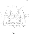
- FIG. 1 illustrates an example medical device 100 that is external, ambulatory, and wearable by a patient 102, and configured to implement one or more configurations described herein.
- the medical device 100 can be a non-invasive medical device configured to be located substantially external to the patient.
- Such a medical device 100 can be, for example, an ambulatory medical device that is capable of and designed for moving with the patient as the patient goes about his or her daily routine.
- the medical device 100 as described herein can be bodily-attached to the patient such as the LifeVest ® wearable cardioverter defibrillator available from ZOLL ® Medical Corporation.
- Such wearable defibrillators typically are worn nearly continuously or substantially continuously for two to three months at a time.
- the wearable defibrillator can be configured to continuously or substantially continuously monitor the vital signs of the patient and, upon determination that treatment is required, can be configured to deliver one or more therapeutic electrical pulses to the patient.
- therapeutic shocks can be pacing, defibrillation, or transcutaneous electrical nerve stimulation (TENS) pulses.
- the medical device 100 can include one or more of the following: a garment 110, one or more sensing electrodes 112 (e.g., ECG electrodes), one or more therapy electrodes 114, a medical device controller 120, a connection pod 130, a patient interface pod 140, a belt 150, or any combination of these.
- a garment 110 one or more sensing electrodes 112 (e.g., ECG electrodes), one or more therapy electrodes 114, a medical device controller 120, a connection pod 130, a patient interface pod 140, a belt 150, or any combination of these.
- at least some of the components of the wearable medical device 100 can be configured to be affixed to the garment 110 (or in some examples, permanently integrated into the garment 110), which can be worn about the patient's torso.
- the controller 120 can be operatively coupled to the sensing electrodes 112, which can be affixed to the garment 110, e.g., assembled into the garment 110 or removably attached to the garment, e.g., using hook and loop fasteners.
- the sensing electrodes 112 can be permanently integrated into the garment 110.
- the controller 120 can be operatively coupled to the therapy electrodes 114.
- the therapy electrodes 114 can also be assembled into the garment 110, or, in some implementations, the therapy electrodes 114 can be permanently integrated into the garment 110.
- the therapy electrodes 114 can include one or more conductive gel deployment devices, e.g., as shown in U.S. Patent Application Publication No. 2015/0005588 entitled "Therapeutic Device Including Acoustic Sensor". Additional examples of gel deployment devices can be found in, for example, U.S. Patent Application No. 15/196,638 filed June 29, 2016 and entitled "Conductive Gel Release and Distribution Devices".
- the sensing electrodes 112 can be configured to be attached at various positions about the body of the patient 102.
- the sensing electrodes 112 can be operatively coupled to the medical device controller 120 through the connection pod 130.
- the sensing electrodes 112 can be adhesively attached to the patient 102.
- the sensing electrodes 112 and therapy electrodes 114 can be included on a single integrated patch and adhesively applied to the patient's body.
- the sensing electrodes 112 can be configured to detect one or more cardiac signals. Examples of such signals include ECG signals, heart sounds, and/or other sensed cardiac physiological signals from the patient. The sensing electrodes 112 can also be configured to detect other types of patient physiological parameters, such as tissue fluid levels, lung sounds, respiration sounds, patient movement, etc. In some examples, the therapy electrodes 114 can also be configured to include sensors configured to detect ECG signals as well as other physiological signals of the patient.
- the connection pod 130 can, in some examples, include a signal processor configured to amplify, filter, and digitize these cardiac signals prior to transmitting the cardiac signals to the controller 120.
- One or more therapy electrodes 114 can be configured to deliver one or more therapeutic defibrillating shocks to the body of the patient 102 when the medical device 100 determines that such treatment is warranted based on the signals detected by the sensing electrodes 112 and processed by the controller 120.
- FIG. 2 is a plan view of an electrode portion of a therapy electrode assembly that includes a gel deployment device and which can be used with a wearable medical device, such as the wearable defibrillator described above with respect to FIG. 1 .
- the gel deployment device when activated, can dispense an electrically conductive gel onto the exposed surface of the electrode portion of the therapy electrode assembly that, in use, is placed most proximate to the subject's body.
- the electrode portion 200 can be a multiple layer laminated structure that includes an electrically conductive layer (disposed on the bottom surface of the therapy electrode 200).
- the electrically conductive layer can be disposed substantially adjacent to the subject's skin, although the conductive layer need not make direct contact with the subject, as portions of the garment 110 (as shown in FIG. 1 ) and/or portions of the subject's clothing can be present between the electrically conductive layer and the subject's skin.
- the garment 110 can include a pocket or other similar structure including a metallic mesh that can be configured to act as an interface between the electrically conductive layer and the patient's skin.
- the metallic mesh can include a knotted fabric having a silver coating.
- various components of the gel deployment device can be disposed on a side of the therapy electrode 200 (e.g., the top-side shown in FIG. 2 ) that is opposite the side on which the conductive layer is formed.
- the therapy electrode 200 can include a plurality of conductive gel reservoirs 210, each of which has a respective gel delivery outlet 220. Each of the gel reservoirs can be fluidly coupled to a fluid channel 230 and a pressure source 240.
- the pressure source 240 can be fluidly coupled to the fluid channel 230 and, when activated by an activation signal, can release a pressurized fluid, such as compressed gas, into the channel 230.
- the hydraulic pressure of the fluid from the activated pressure source 240 in the fluid channel 230 can force the conductive gel stored in each of the plurality of gel reservoirs out of the plurality of gel delivery outlets 220 through apertures formed in the electrically conductive layer and onto the exposed surface of the electrically conductive layer that, in use, is placed most proximate to the subject's body.
- the apertures in the electrically conductive layer can be substantially aligned with the plurality of gel delivery outlets 220 so that when activated, the electrically conductive gel can be dispensed onto the exposed surface of the electrode portion that is disposed most proximate to the subject's body.
- a pressure source can be configured to facilitate a chemical reaction.
- an amount of pressurized fluid can be produced and directed to, for example, a plurality of conductive gel reservoirs for facilitating release of the conductive gel stored therein.
- the pressurized fluid can include any non-noxious gas. Examples are discussed above.
- FIGS. 3 and 4 illustrate various example configurations for a pressure source that incorporates a chemical reaction to produce a pressurized fluid.
- the pressure sources can include a case design that allows for the storage and timely mixing of two or more chemicals to produce the pressurized fluid.
- the chemical reaction can include mixing two chemicals together to produce a chemical reaction, resulting in the creation of a pressurized fluid.
- the chemical reaction can include, for example, mixing two or more fluids together, mixing one or more fluids with one or more solids, or mixing two or more solids together.
- the chemical reaction can include mixing an acid with a base to produce a pressurized fluid.
- the resulting carbon dioxide gas can be directed by the pressure source through an exit port of the pressure source and into, for example, fluid channel 230 as described above.
- the carbon dioxide gas can apply hydraulic pressure to the individual gel reservoirs 210, thereby facilitating release of conductive gel stored within the conductive gel reservoirs.
- a certain pressure level of the pressurized fluid can be configured to, for example, facilitate conductive gel release in a conductive gel deployment device.
- the pressure level of the pressurized fluid can be configured based upon the internal volume of the fluid channel (as well as any additional spaces the pressurized fluid is configured to fill, such as air gaps or spaces in the gel reservoirs).
- the pressure level can also be configured based upon an applied pressure level for releasing the conductive gel from the gel reservoirs.
- the gel reservoirs can include a frangible seal configured to release the conductive gel at an applied pressure of about 15 psi.
- This applied pressure in combination with the internal volume the pressurized fluid is configured to fill, can be used to determine a total overall pressure level for the pressurized fluid.
- the combined internal volume the pressurized fluid is configured to fill can be approximately 25 cubic centimeters.
- the internal volume the pressurized fluid is configured to fill can be approximately 5 - 50 cm 3 .
- the internal volume can change as the conductive gel is released (i.e., to account for the space in the gel reservoirs previously occupied by the conductive gel).
- the initial internal volume can be approximate 5-10 cm 3 and the final internal volume can be approximately 10 - 50 cm 3 .
- the pressure sources including chemical reactions as described below can be configured to produce or release a pressurized fluid at approximately 5 to 100 psi. In some implementations, the pressure sources including chemical reactions as described below can be configured to produce or release a pressurized fluid at approximately 15 psi to 40 psi. In some examples, the pressure sources including chemical reactions can be configured to produce or release a pressurized fluid at about 35 psi, or at a similar pressure to fill the internal volume (such as a one or more fluid conduits used in a gel deployment device as described above) to a pressure of about 35 psi.
- the chemical reaction can include applying an acidic solution to a reactive metal.
- nucleation process can be used to produce an amount of pressurized fluid.
- a liquid including a suspended gas (such as a carbonated liquid including suspended carbon dioxide) can be mixed with a solid including a surface covered with microscopic features such as peaks and valleys.
- the suspended gas attaches to the microscopic features, forming bubbles around all the features.
- excess gas can be released from the liquid as a pressurized fluid. As above, this pressurized fluid can be directed to the gel reservoirs for facilitation of the conductive gel release.
- FIG. 3 illustrates a pressure source 300 configured to produce a pressurized fluid as, for example, a byproduct of a chemical reaction.
- the pressure source 300 can be integrated into a therapy electrode such as therapy electrode 200 as discussed above, e.g., replacing pressure source 240 as discussed in reference to therapy electrode 200.
- a controller such as medical device controller 120, can be operably connected to the pressure source 300.
- the medical device controller 120 can be configured to provide an electrical signal to the pressure source 300 prior to delivery of, for example, a therapeutic shock to a patient.
- the electrical signal can be configured to facilitate or otherwise initiate a chemical reaction configured to produce a pressurized fluid.
- the pressurized fluid can then be directed through the fluid channel 230 to the conductive gel reservoirs 210, thereby causing release of the conductive gel stored therein.
- the pressurized fluid can include any non-noxious gas. Examples are discussed above.
- the pressure source 300 can include a case 302 configured to contain the chemicals and other components related to facilitating a chemical reaction.
- a case 302 configured to contain the chemicals and other components related to facilitating a chemical reaction.
- various materials and methods of manufacture can be used to construct the case 302.
- the chemical reaction used by the pressure source 300 can be configured to produce approximately 35 psi.
- the material used for the manufacture of case 302 can be selected and configured to withstand an applied pressure greater than 35 psi plus some safety margin (e.g., an additional about 1-50 psi).
- the case 302 can be made of plastic, metal, metal alloy, ceramic, and/or a combination thereof.
- the case 302 can be molded from a thermoplastic polymer and/or a thermoset polymer.
- the case 302 can be shaped such that any pressurized fluids contained therein are directed in a particular direction.
- the case 302 can be shaped like a cone having an opening or exit port at the point or narrow end, a tapering cylinder having an opening or exit port at the narrow end, a pyramid having an opening or exit port at one of the points, and other similar shapes that provide one or more geometric features for directed pressurized fluid flow.
- the case 302 is made of a clear or transparent material to allow visual monitoring of the contents of the case.
- the case 302 can be made of a thermoplastic material.
- the thermoplastic material can be high density polyethylene, low density polyethylene, ultra high-molecular weight polyethylene, polypropylene, nylon and polyethylene terephthalate. Alternatively, it is understood that any viable thermoplastic material may be used.
- the material may be transparent, opaque or partially opaque.
- thermoplastic polymers examples include polystyrene, polyetherketone, polyetheretherketone, polyetherketoneketone, polyethersulfone, polycarbonate, polyolefin such as polypropylene, polyethylene, or cyclic olefin, polyester such as polyethylene terephthalate or polyethylene napthalate, polyamide (nylon), or other well-known materials in the plastics art.
- Amorphous plastics such as amorphous nylon exhibit high transparency and may also be suitable.
- Thermoset resins include epoxy, epoxy novolac, phenolic, polyurethane, and polyimide.
- the case 302 can be manufactured from a copolymer such as an ethylene acid copolymer through an injection molding or thermoforming process.
- the case 302 can be manufactured from an ionomer resin of ethylene acid copolymer ("the ionomer resin") having a density of approximately 0.94 g/cm 3 .
- the tensile strength of the ionomer resin can be configured based upon the thickness of the ionomer resin.
- An example of a commercially available ionomer resin of ethylene acid copolymer is Surlyn ® , which is available from DuPont TM .
- the thickness of the walls of the case 302 can be configured such that the case 302 is configured to withstand an applied pressure of greater than, for example, about 100 psi.
- the ionomer resin has a thickness of approximately 0.125 inches can withstand an applied pressure of approximately 250 psi.
- a clear plastic such as polycarbonate or a composite plastic blend (e.g., an ethylene acid copolymer and polycarbonate blend) can be used to manufacture case 302 if, for example, the case 302 is to be subjected to visual inspection (e.g., to confirm that the chemical reaction has not occurred prior to installation of the pressure source).
- a thickness for the walls of the case 302 can be configured such that the case is configured to withstand the applied pressure as described above.
- case 302 can be manufactured from a material having a relatively low water vapor transmission rate.
- the ionomer resin has a water vapor transmission rate of about 0.8 g/100in 2 /day.
- Using a material with a low permeability such as the ionomer resin can provide an advantage of a longer shelf-life of a chemical reaction-based pressure source relative to conventional configurations as the rate of evaporation of any liquid chemicals through the ionomer resin is low.
- the case 302 can be manufactured from a plastic material using an injection molding process.
- the case 302 can be manufactured from the ionomer resin in a design (e.g., having a specific geometry and wall thickness) capable of both housing enough chemicals as needed for the chemical reaction while still maintaining its structural integrity after the chemical reaction (e.g., the case 302 is configured to handle the pressure of the fluid produced as a result of the chemical reaction).
- the case 302 can be formed by a thermoforming process, or other similar forming process.
- the case 302 can also be made from a non-reactive metal such as stainless steel.
- the stainless steel can be stamped, rolled, or similarly formed to contain the chemicals and other components related to facilitating the chemical reaction.
- the case 302 can be configured and formed such that it defines at least one exit port 304 for directing a pressurized fluid (produced by, for example, a chemical reaction within the case 302).
- the exit port 304 can include a valve (e.g., a one-way flow valve) to prevent contamination or foreign chemicals from entering into the case 302.
- the valve can be configured to open at a predetermined pressure (e.g., about 5 psi to 20 psi) to prevent chemicals from escaping the case 302 prior to the chemical reaction. In some examples, the valve can be configured to open at about 10 psi.
- the pressure source 300 can include a first chemical 306 and a second chemical 308.
- the first chemical 306 can be a solid base loaded into the case 302 in, for example, a powder or compressed solid form.
- the second chemical 308 can be contained in an isolating container 310.
- the isolating container 310 can be configured to act as a mechanical barrier positioned to provide isolation of the second chemical 308 from the first chemical 306 until the second chemical 308 is released or otherwise mixed with first chemical 306, thereby eliminating unwanted and/or untimely reactions.
- the second chemical 308 can be a liquid chemical such as an acid.
- the isolating container 310 can be filled with the second chemical prior to insertion into the case 302.
- the second chemical 308 can be filled into the isolating container 310 at, for example, 15 psi to 35 psi.
- the second chemical 308 can be filled into the isolating container 310 at about 25 psi.
- an external pressure applying device such as a leaf spring or an elastic band can apply an external pressure to the isolating container 310.
- a set of leaf springs 314 can be positioned adjacent to the isolating container 310 and be configured to apply an external pushing force against the isolating container 310.
- the leaf springs 314 can assist in the release of the second chemical 308 from the isolating container 310.
- the first chemical 306 is a metal carbonate or bicarbonate and the second chemical 308 is an acid.
- the metal carbonate or bicarbonate and the acid mix together, a reaction occurs to produce carbon dioxide, salt, and water.
- the metal carbonate can be any metal carbonate.
- the metal carbonate is lithium carbonate, sodium carbonate, potassium carbonate, rubidium carbonate, cesium carbonate, beryllium carbonate, magnesium carbonate, calcium carbonate, strontium carbonate, barium carbonate, manganese carbonate, iron carbonate (siderite), cobalt carbonate, nickel carbonate, copper carbonate, zinc carbonate, silver carbonate, cadmium carbonate (otavite), aluminum carbonate, thallium carbonate, lead carbonate, ammonium carbonate, bismuth subcarbonate, lanthanum carbonate, uranyl carbonate, or mixtures thereof.
- the metal carbonate is sodium carbonate, potassium carbonate, magnesium carbonate, calcium carbonate, copper carbonate, zinc carbonate, ammonium carbonate, or mixtures thereof.
- the metal bicarbonate can be any metal bicarbonate.
- the metal bicarbonate is lithium bicarbonate, sodium bicarbonate, potassium bicarbonate, cesium bicarbonate, magnesium bicarbonate, calcium bicarbonate, ammonium bicarbonate, or mixtures thereof.
- the metal bicarbonate is sodium bicarbonate, potassium bicarbonate, magnesium bicarbonate, calcium bicarbonate, ammonium bicarbonate, or mixtures thereof.
- the acid can be any acid in a concentration such that it can react to produce carbon dioxide but can be safely stored in the case 302.
- the acid can be a mineral acid, sulfonic acid, carboxylic acid, halogenated carboxylic acid, or mixtures thereof.
- the acid is hydrofluoric acid, hydrochloric acid, hydrobromic acid, hydroiodic acid, hypochlorous acid, chlorous acid, chloric acid, perchloric acid, hypobromous acid, bromous acid, bromic acid, perbromic acid, hypoiodous acid, iodous acid, iodic acid, periodic acid, sulfuric acid, nitric acid, phosphoric acid, fluorosulfuric acid, fluoroantimonic acid, fluoroboric acid, hexafluorophosphoric acid, chromic acid, methanesulfonic acid, ethanesulfonic acid, benzensulfonic acid, p-toluenesulfonic acid, trifluoromethanesulfonic acid, polystyrene sulfonic acid, acetic acid, citric acid, formic acid, gluconic acid, lactic acid, oxalic acid, tartaric acid fluoroacetic acid,
- the concentration of the acid can be adjusted by adding a solvent such as water.
- the concentration of the acid is adjusted such that the pH of the acid is in the range of about 2 to less than 7.
- acids with a pH of less than 2 can be used in small quantities - e.g., less than 0.1 gm in case having a volume of about 25 cm 3 .
- the pressure source 300 can include a first chemical 306 and a second chemical 308, wherein the first chemical 306 and the second chemical 308 are selected to produce nitrogen gas or oxygen gas.
- the first chemical 306 can be sodium chlorate, potassium perchlorate, potassium permanganate, potassium iodide, or mixtures thereof and the second chemical 308 can be hydrogen peroxide, barium peroxide, iron powder, or mixtures thereof.
- Yeast can be used as the first chemical 306 in some implementations.
- the second chemical 308 is hydrogen peroxide.
- the second chemical 308 is hydrogen peroxide and the first chemical 306 can be one or a mixture of potassium iodide, yeast, and potassium permanganate.
- the first chemical 306 can be an ammonium compound and the second chemical 308 can be a chemical that reacts with the ammonium compound to produce nitrogen gas.
- the ammonium compound include ammonium nitrite, ammonium nitrate, ammonium, chloride, ammonium dichromate, ammonium hydroxide, or mixtures thereof.
- the second chemical 408 can be sodium nitrite, potassium nitrite, calcium nitrite, or other nitrite compound.
- Nitrogen gas can also be produced by the reaction of hypochlorites or hypobromites on ammonia, reduction of nitric and/or nitrous oxides, reaction of ammonia gas with a nitrite compound, or combinations of these reactions.
- the quantities provided of the first chemical 306 and the second chemical 308 can be varied depending upon the size and shape of the case 302 and the amount of pressure the chemical reaction is configured to produce. For example, to produce a higher pressure than, for example, the implementations as described above, additional quantities of the first chemical 306 and the second chemical 308 can be used in a similarly shaped case 302. In some implementations, more reactive chemicals can be used to produce a pressurized fluid having a higher pressure level.
- the first chemical 306 can be added in an amount of about 0.001 grams to about 1000 grams. In some embodiments the first chemical 306 can be added in an amount of 0.001 to about 50 wt% of the total amount of the first chemical 306 and the second chemical 308.
- the second chemical 308 can be added in an amount of about 0.001 grams to about 1000 grams. In some embodiments the second chemical 308 can be added in an amount of 0.001 to about 50 wt% of the total amount of the first chemical 306 and the second chemical 308.
- the first chemical 306 and the second chemical 308 are present in an amount sufficient to produce an amount of carbon dioxide, which produces a pressure of from about 5 psi to about 100 psi. In some implementation, the pressure is from about 10 psi to about 70 psi. In some implementations, the pressure is from about 15 psi to about 50 psi. In some implementations, the pressure is from about 15 psi to about 35 psi.
- the isolating container 310 can be made from a membrane or another material that, in response to an applied heat or force, can be structurally compromised to release the second chemical 308 such that it mixes with the first chemical 306.
- the isolating container 310 can be configured such that it is structurally compromised upon application of heat from one or more heat sources. For example, as shown in FIG. 3 , a heating element such as resistive wire 312 can be placed adjacent to the isolating container 310, e.g., wrapped around the isolating container 310 or otherwise pressed against a portion of the isolating container 310.
- the isolating container 310 can be formed from a meltable membrane such as a thermoplastic configured to melt at a predetermined melting point.
- the isolating container 310 can be manufactured from polyethylene having a melting point of approximately 239-275°F.
- the isolating container 310 can be manufactured from a material having a low evaporation permeability (e.g., a material having a low water vapor transmission rating) when compared to conventional thermoplastics.
- a material with a low evaporation permeability can provide the advantage of an extended shelf life of the pressure source 300 as the second chemical 308 is less likely to evaporate or leak from the isolating container 310.
- the resistive wire 312 can be constructed from a material that produces heat in response to an applied current.
- the resistive wire 312 can be made from nickel chromium wire.
- the thickness of the resistive wire 312 can be selected such that the temperature of the wire, when an appropriate current is applied, exceeds the melting point of the isolating container 310.
- a 20-gauge to a 28-gauge wire can be used, the wire configured to heat to approximately 350°F to 450°F.
- a 24-gauge nickel chromium wire having a 0.020-inch diameter can heat to 400°F at relatively low amperages as compared to a similarly sized copper wire.
- a current can be applied to the resistive wire 312.
- the resistive wire 312 can heat up past the melting point of the isolating container 310, thereby causing a puncturing or rupturing of the isolating container 310 and release of the second chemical 308 (e.g., through the internal pressure of the second chemical 308 within the isolating container 310 as described above).
- the second chemical 308 can mix with the first chemical 306, thereby producing a pressurized fluid.
- the shape of the case 302 can direct the pressurized fluid out of the exit port 304.
- the exit port 304 can be connected to a fluid channel in, for example, the therapy electrode 200 as described above in regard to FIG. 2 .
- the pressurized fluid can be directed through the fluid channel to one or more gel reservoirs, thereby facilitating release of conductive gel stored in the gel reservoirs.
- alternate release methods can be used to puncture or otherwise compromise the isolating container 310 and release the second chemical 308.
- a puncturing pin and actuation device (such as a small solenoid) can be used to puncture the isolating container 310.
- the isolating container 310 can be configured as a syringe configured to eject a quantity of the second chemical 308 in response to, for example, a force pressing against a plunger of the syringe.
- an alternative melting device can be used in place of the resistive wire 312.
- a small laser can be configured to focus an emitted laser beam or pulse onto the isolating container 310 to melt a small portion of the isolating container 310.
- the medical device controller 120 can be configured to deliver an appropriate electrical signal (e.g., at a high enough current to heat the resistive wire 312) at the appropriate time (e.g., providing for adequate timing for the chemical reaction to occur and for the subsequent release of the conductive gel).
- the pressure source 300 can also include a localized power source that, in response to the signal from the medical device controller 120, is configured to provide a current to the resistive wire 312, thereby heating the resistive wire.
- the pressure source 300 can be integrated into a therapy electrode such as therapy electrode 200 as discussed above, e.g., replacing pressure source 240 as discussed in reference to therapy electrode 200.
- a controller such as medical device controller 120, can be operably connected to the pressure source 300.
- the medical device controller 120 can be configured to provide an electrical signal to the pressure source 300 prior to delivery of, for example, a therapeutic shock to a patient.
- the electrical signal can include a current to be directed to the resistive wire 312, thereby heating the resistive wire 312. Once heated, the resistive wire 312 can melt the isolating container 310, resulting in the release of the second chemical 308 from the isolating container 310.
- the second chemical 308 can mix with the first chemical 306, causing a chemical reaction.
- the chemical reaction can produce a pressurized fluid (e.g., pressurized carbon dioxide gas), which is directed through the exit port 304.
- the pressurized fluid can flow through the fluid channel 230 to each of the conductive gel reservoirs 210.
- the pressurized fluid can cause release of the conductive gel contained within the conductive gel reservoirs 210, thereby resulting in the conductive gel flowing through the apertures in the electrically conductive layer that is substantially proximate the patient's body.
- the medical device controller 120 can then facilitate delivery of the therapeutic shock.
- the isolating container 310 is shown as positioned in the center of the case 302 for explanatory purposes only. In certain implementations, the isolating container 310 can be positioned against a wall of the case 302, at one end of the case 302, or at any location within the case 302 that still provides for adequate chemical mixing prior to the chemical reaction. Additionally, the pressure source 300 is shown as having the second chemical 308 positioned inside the isolating container 310. In other designs, the first chemical 306 can be placed within the isolating container 310 and the second chemical 308 can be arranged solely inside case 302.
- FIG. 4 illustrates a pressure source 400 configured to produce a pressurized fluid as a result of a chemical reaction.
- the pressure source 400 can be integrated into a therapy electrode such as therapy electrode 200 as discussed above, e.g., replacing pressure source 240 as discussed in reference to therapy electrode 200.
- a controller such as medical device controller 120, can be operably connected to the pressure source 400.
- the medical device controller 120 can be configured to provide an electrical signal to the pressure source 400 prior to delivery of, for example, a therapeutic shock to a patient.
- the electrical signal can be configured to facilitate or otherwise initiate a chemical reaction configured to produce a pressurized fluid.
- the pressurized fluid can then be directed through the fluid channel 230 to the conductive gel reservoirs 210, thereby causing release of the conductive gel stored therein.
- the pressurized fluid can include any non-noxious gas. Examples are discussed above.
- the pressure source 400 can include a case 402 configured to contain the chemicals and other components related to facilitating a chemical reaction.
- the case 402 can be formed such that it can define at least one exit port 404 for directing a pressurized fluid (produced by, for example, a chemical reaction within the case 402).
- the exit port 404 can include a valve (e.g., a one-way flow valve) to prevent contamination or foreign chemicals from entering into the case 402.
- the valve can be configured to open at a predetermined pressure (e.g., 10 psi) to prevent chemicals from escaping the case 402 prior to the chemical reaction.
- case 402 can be made from the same material(s) and has the same characteristics as discussed above with regard to case 302.
- the pressure source 400 can include a first chemical 406 and a second chemical 408.
- the first chemical 406 can be a metal carbonate or bicarbonate.
- the first chemical 406 can be a solid such as sodium bicarbonate loaded into the case 402 in, for example a powder or compressed solid form.
- the second chemical 408 remains separated from the first chemical 406 by, for example, a piston 410.
- the second chemical 408 is an acid.
- the metal carbonate can be any metal carbonate, as discussed above.
- the metal bicarbonate can be any metal bicarbonate as discussed above.
- the acid can be any acid as discussed above.
- the piston 410 can be constructed from a plastic such as polyethylene, or a metal such as stainless steel or aluminum.
- the piston 410 can also include one or more O-rings 411 positioned to prevent leakage of the second chemical 408 as well as to act as a mechanical barrier configured to create a seal between the first chemical and the second chemical.
- the O-rings 411 can be made from a thermoplastic elastomer such as synthetic rubber.
- the O-rings 411 can also be sized to produce a friction fit between the piston 410 and the case 402.
- the piston 410 can be connected to a movement causing device such as a solenoid 412.
- the solenoid 412 can be configured to exert a pushing force on the piston 410, thereby moving the piston 410 toward the first chemical 406 (as shown in FIG. 4 ), causing the release of the second chemical 408 into the first chemical 406.
- the second chemical 408 can mix with the first chemical 406, thereby producing a pressurized fluid.
- the shape of the case 402 can be configured and design to direct the pressurized fluid out of the exit port 404.
- the exit port 404 can be connected to a fluid channel in, for example, the therapy electrode 200 as described above in regard to FIG. 2 .
- the pressurized fluid can be directed through the fluid channel to one or more gel reservoirs, thereby facilitating release of conductive gel stored in the gel reservoirs.
- the medical device controller 120 can be configured to deliver an appropriate electrical signal (e.g., at a high enough current to move the solenoid 412) at the appropriate time (e.g., providing for adequate timing for the chemical reaction to occur and for the subsequent release of the conductive gel).
- the pressure source 400 can also include a localized power source that, in response to the signal from the medical device controller 120, is configured to provide a current to the solenoid 412, thereby facilitating movement of the solenoid 412.
- the pressure source 400 can be integrated into a therapy electrode such as therapy electrode 200.
- the pressure source 400 can replace pressure source 240 as discussed in reference to therapy electrode 200.
- a controller such as medical device controller 120, can be operably connected to the pressure source 400.
- the medical device controller 120 can be configured to provide an electrical signal to the pressure source 400 prior to delivery of, for example, a therapeutic shock to a patient.
- the electrical signal can be directed to the solenoid 412.
- the solenoid 412 can move the piston 410 toward, for example, exit port 404. Such movement of the piston 410 can result in the second chemical 408 being released into the first chemical 406.
- the second chemical 408 can mix with the first chemical 406, causing a chemical reaction.
- the chemical reaction can produce a pressurized fluid (e.g., pressurized carbon dioxide gas) which can be directed through the exit port 404.
- the pressurized fluid can flow through the fluid channel 230 to each of the conductive gel reservoirs 210.
- the pressurized fluid can facilitate release of the conductive gel contained within the conductive gel reservoirs 210, resulting in the conductive gel flowing through the apertures in the electrically conductive layer that is proximate the patient's body.
- the medical device controller 120 can then deliver the therapeutic shock.
- pressure sources 300 and 400 are described above by way of example only. Similarly, the chemicals described in relation to the pressure sources 300 and 400, as well as the resulting chemical reactions and pressurized fluids produced by those reactions are described by way of example only.
- the pressure source 400 can include a first chemical 406 and a second chemical 408, wherein the first chemical 406 and the second chemical 408 are selected to produce nitrogen gas or oxygen gas.
- the first chemical 406 can be sodium chlorate, potassium perchlorate, potassium permanganate, potassium iodide, or mixtures thereof and the second chemical 408 can be hydrogen peroxide, barium peroxide, iron powder, or mixtures thereof.
- Yeast can be used as the first chemical 406 in some implementations.
- the second chemical 408 is hydrogen peroxide.
- the second chemical 408 is hydrogen peroxide and the first chemical 406 can be one or a mixture of potassium iodide, yeast, and potassium permanganate.
- the first chemical 406 can be an ammonium compound and the second chemical 408 can be a chemical that reacts with the ammonium compound to produce nitrogen gas.
- the ammonium compound include ammonium nitrite, ammonium nitrate, ammonium, chloride, ammonium dichromate, ammonium hydroxide, or mixtures thereof.
- the second chemical 408 can be sodium nitrite, potassium nitrite, calcium nitrite, or other nitrite compound.
- Nitrogen gas can also be produced by the reaction of hypochlorites or hypobromites on ammonia, reduction of nitric and/or nitrous oxides, reaction of ammonia gas with a nitrite compound, or combinations of these reactions.
- a pressure source (e.g., one of pressure sources 300 and 400) can include two chemicals configured to mix such that a resulting reaction produces an amount of pressurized fluid containing a gas such as carbon dioxide.
- the pressurized fluid can include any non-noxious gas. Examples are discussed above.
- the pressurized fluid is produced from mixing a first chemical and a second chemical to produce carbon dioxide, where the first chemical is a metal carbonate or bicarbonate and the second chemical is an acid.
- the reaction of the metal carbonate or bicarbonate with the acid produces safe byproducts including salt, water, and carbon dioxide as shown below in reaction (1).
- the chemical reaction can include mixing an acid such as citric or acetic acid with a basic solid such as sodium bicarbonate to produce carbon dioxide gas with water, and sodium acetate.
- a specific chemical reaction example of reaction (1) is shown below in reaction (2). NaHCO 3 + CH 3 COOH -> CO 2 + H 2 O + CH 3 COONa (2)
- the base can be added in an amount of about 0.001 grams to about 1000 grams. In some embodiments the base can be added in an amount of 0.001 to about 50 wt% of the total amount of the base and the acid.
- the acid can be added in an amount of about 0.001 grams to about 1000 grams. In some embodiments the acid can be added in an amount of 0.001 to about 50 wt% of the total amount of the base and the acid.
- the first chemical or the second chemical can be a limiting agent.
- a specific quantity of the first chemical can be determine that, upon reaction, will produce an appropriate amount of pressurized gas.
- An amount of the second chemical can be determine that would fully react with the specific quantity of the first chemical.
- an additional buffer amount of the second chemical can be included.
- an additional 5-25% of the second chemical can be included.
- the first chemical would act as a limiting agent as the first chemical would fully react with the second chemical (with an amount of excess second chemical remaining, i.e., the additional buffer).
- the base and the acid are present in an amount sufficient to produce an amount of carbon dioxide, which produces a pressure of from about 5 psi to about 100 psi. In some implementations, the pressure is from about 10 psi to about 70 psi. In some implementations, the pressure is from about 15 psi to about 50 psi. In some implementations, the pressure is from about 15 psi to about 35 psi.
- a specific amount of pressurized fluid can be created during the chemical reaction, the pressurized fluid being directed to individual gel reservoirs to facilitate release of conductive gel stored therein.
- the pressurized fluid can be configured to fill an internal volume of 25 cm 3 to a pressure of approximately 50 psi (e.g., a 35 psi pressure to facilitate release of the conductive gel from the gel reservoirs plus a 15 psi safety buffer to account for any unreacted chemicals or other potential complications during the chemical reaction).
- the resulting pressurized fluid is carbon dioxide, which has a molar mass of 44.0095 g/mol at room temperature (e.g., approximately 295K).
- the pressure includes a safety buffer. This buffer can also be used to account for any changes in temperature during the reaction.
- the inventors have used commercially available acetic acid to produce carbon dioxide.
- the wire 312 can be heated, thereby causing a structural compromise of the isolating container 310 (e.g., the wire 312 melts a hole in isolating container 310).
- the acetic acid can then be released from the isolating container 310.
- leaf springs 314 can provide an external force against the isolating container 310, causing quicker release of the acetic acid.
- the acetic acid can then mix with the sodium bicarbonate in the case 302, causing creation of the carbon dioxide gas.
- the carbon dioxide gas can be directed out of the case 302 via the exit port 304.
- the carbon dioxide gas can then be directed by one or more fluid conduits, such as fluid channel 230, to the gel reservoirs.
- the speed of the reaction can be a critical consideration. For example, in a wearable defibrillator, when a treatment shock is imminent, it may be desirable to have the conductive gel deploy as quick as possible. In such an implementation, the amounts of the chemicals can be changed to produce a quicker reaction. For example, the amounts of sodium bicarbonate and acetic acid can be increased.
- a pressure source can include between 0.50 grams and 2.5 grams of sodium bicarbonate. Similarly, a pressure source can include between 0.40 grams and 2.2 grams of acetic acid. In a particular example, a pressure source can include 1.5 grams of sodium bicarbonate and 0.50 grams of acetic acid.
- acetic acid As the acetic acid is used in a liquid state, a lower ratio (as compared to the total amount of chemicals used in the reaction) of acetic acid can be used as compared to the ratio of the solid sodium bicarbonate.
- a higher ratio of the sodium bicarbonate the chances are increased that the acetic acid will fully react with the sodium bicarbonate, thereby maximizing the amount of carbon dioxide gas that can be produced by the amount of acetic acid used. Any excess sodium bicarbonate will remain in the pressure source in an unreacted state.
- the internal volume that the pressurized fluid is intended to fill can vary between implementation as well.
- the total internal volume can vary between 10 - 50 cm 3 .
- the amount of the individual chemicals can be reduced as a lesser amount of pressurized fluid may be used.
- the amount of the individual chemicals can be increased as a greater amount of pressurized fluid may be used.
- a pressure source can include between 0.25 grams and 5 grams of sodium bicarbonate.
- a pressure source can include between 0.15 and 4 grams of acetic acid.
- changing the chemicals reacting with one another to produce a different gas can be used to control both the volume and speed of a reaction.
- oxygen or nitrogen can be generated from a chemical reaction.
- the pressure source 300 can include a first chemical 306 and a second chemical 308, wherein the first chemical 306 and the second chemical 208 are selected to produce nitrogen gas or oxygen gas.
- the first chemical 306 can be sodium chlorate, potassium perchlorate, potassium permanganate, potassium iodide, or mixtures thereof and the second chemical 308 can be hydrogen peroxide, barium peroxide, iron powder, or mixtures thereof.
- Yeast can be used as the first chemical 306 in some implementations.
- the second chemical 308 is hydrogen peroxide.
- the second chemical 308 is hydrogen peroxide and the first chemical 306 can be one or a mixture of potassium iodide, yeast, and potassium permanganate.
- the first chemical 306 can be an ammonium compound and the second chemical 308 can be a chemical that reacts with the ammonium compound to produce nitrogen gas.
- the ammonium compound include ammonium nitrite, ammonium nitrate, ammonium, chloride, ammonium dichromate, ammonium hydroxide, or mixtures thereof.
- the second chemical 308 can be sodium nitrite, potassium nitrite, calcium nitrite, or other nitrite compound.
- Nitrogen gas can also be produced by the reaction of hypochlorites or hypobromites on ammonia, reduction of nitric and/or nitrous oxides, reaction of ammonia gas with a nitrite compound, or combinations of these reactions.
- the chemical reaction can include mixing an aqueous peroxide such as hydrogen peroxide with a metallic salt such as potassium iodide to produce oxygen gas.
- a reaction results in the catalyzed decomposition of the hydrogen peroxide to produce water and oxygen gas.
- the hydrogen peroxide reacts with iodide ions from the potassium iodide to produce the oxygen gas.
- the reactions can be represented as: H 2 O 2 + I - ⁇ H 2 O + IO - (4) H 2 O 2 + IO - ⁇ H 2 O + O 2 + I - (5)
- H 2 O 2 is hydrogen peroxide
- I + is an iodide ion
- H 2 O is water
- IO - is a hypoiodite ion
- O 2 is oxygen gas.
- a specific amount of pressurized fluid can be created during the chemical reaction, the pressurized fluid being directed to individual gel reservoirs to facilitate release of conductive gel stored therein.
- the pressurized fluid can be configured to fill an internal volume of 10 cm 3 to a pressure of approximately 50 psi (e.g., a 35 psi pressure to facilitate release of the conductive gel from the gel reservoirs plus a 15 psi safety buffer to account for any unreacted chemicals or other potential complications during the chemical reaction).
- the resulting pressurized fluid is oxygen gas, which has a molar mass of 32.00 g/mol at room temperature (e.g., approximately 295K).
- the desired pressure 50 psi at standard atmospheric pressure
- the molar mass of the carbon dioxide an amount of carbon dioxide to be produced during the chemical reaction can be calculated using the ideal gas law.
- the amount of hydrogen peroxide and potassium iodide to include can be determined based upon the resulting amount of O 2 produced.
- 0.11g of O 2 produces a pressure that will result in release of the conductive gel from the conductive gel reservoirs as described above.
- O 2 has a molar mass of 32.00 g/mol.
- 0.11 g equals approximate 0.0046 moles of O 2 .
- approximately 0.0046 moles of both potassium iodide and hydrogen peroxide should be included in the reaction.
- Hydrogen peroxide has a molar mass of 34.015 g/mol. As such, approximately 0.0046 moles of hydrogen peroxide is 0.16 grams.
- Potassium iodide has a molar mass of 166.00 g/mol. As such, approximately 0.0046 moles of potassium iodide is 0.76 grams. As such, to produce 0.11 grams of O 2 , at least 0.16 grams of hydrogen peroxide should fully react with 0.76 grams of potassium iodide.
- approximately 0.76 grams of potassium iodide (e.g., in a powdered form) can be used for the first chemical, and approximately 0.16 grams of hydrogen peroxide can be used for the second chemical.
- approximately 0.76 grams of powdered potassium iodide can be loaded into the case 302.
- approximately 0.16 grams of hydrogen peroxide can be loaded into isolating container 310.
- Tables 3-22 show amounts of carbon dioxide, nitrogen, and oxygen gas needed for volumes ranging from 5 cm 3 to 100 cm 3 .
- the wire 312 can be heated, thereby causing a structural compromise of the isolating container 310 (e.g., the wire 312 melts a hole in isolating container 310).
- the hydrogen peroxide can then be released from the isolating container 310.
- leaf springs 314 can provide an external force against the isolating container 310, causing quicker release of the hydrogen peroxide.
- the hydrogen peroxide can then mix with the potassium iodide in the case 302, causing catalytic decomposition of the hydrogen peroxide into water and oxygen gas.
- the oxygen gas can be directed out of the case 302 via the exit port 304.
- the oxygen gas can then be directed by one or more fluid conduits, such as fluid channel 230, to the gel reservoirs.
- a pressure source can include between 0.20 grams and 2.5 grams of hydrogen peroxide.
- a pressure source can include between 0.80 grams and 5.0 grams of potassium iodide.
- a pressure source can include 0.5 grams of hydrogen peroxide and 1.50 grams of potassium iodide.
- the internal volume that the pressurized fluid is intended to fill can vary between implementation as well.
- the total internal volume can vary between 10 - 50 cm 3 .
- the amount of the individual chemicals can be reduced as a lesser amount of pressurized fluid may be used.
- the amount of the individual chemicals can be increased as a greater amount of pressurized fluid may be used.
- a pressure source can include between 0.10 grams and 5 grams of hydrogen peroxide.
- a pressure source can include between 0.50 grams and 7.5 grams of potassium iodide.
- a pressure source can include a pressurized fluid reservoir as well as a mechanical mechanism for facilitating release of a pressurized fluid contained within the fluid reservoir.
- the released pressurized fluid can be directed to, for example, a plurality of conductive gel reservoirs for facilitating release of conductive gel stored therein.
- FIGS. 5A-11B illustrate various examples of pressure sources that incorporate a pressurized fluid reservoir, e.g., pressure sources 500 ( FIG. 5A ), 520 ( FIG. 5B ), 600 ( FIG. 6 ), 700 ( FIG. 7 ), 800 ( FIG. 8 ), 900 ( FIG. 9 ), 1000 ( FIG. 10 ), and 1100 ( FIG. 11 ).
- a pressure source as described in FIGS. 5A-11 can be integrated into a therapy electrode such as therapy electrode 200 as discussed above, e.g., replacing pressure source 240 as discussed in reference to therapy electrode 200.
- a controller such as medical device controller 120, can be operably connected to the pressure source.
- the medical device controller 120 can be configured to provide an electrical signal to the pressure source prior to delivery of, for example, a therapeutic shock to a patient.
- the electrical signal can be configured to facilitate or otherwise initiate a release of the pressurized fluid from the pressurized fluid reservoir.
- the pressurized fluid can then be directed through the fluid channel 230 to the conductive gel reservoirs 210, thereby causing release of the conductive gel stored therein.
- the pressure sources as described in relation to FIGS. 5A-11 include, for example, a preloaded amount of pressurized fluid contained in a sealed or otherwise isolated reservoir.
- the pressurized fluid can be one of compressed nitrogen gas or compressed carbon dioxide gas.
- the pressurized fluid can be one of compressed argon gas stored in a high compression pressure vessel.
- the design of and materials used to manufacture the reservoir can be chosen based upon the type of pressurized fluid being used, as well as the pressure that the pressurized fluid is to be contained at.
- the reservoir can be manufactured from a metal such as stainless steel or aluminum.
- the thickness of the walls of the sealed reservoir can be sized such that the reservoir contains the pressurized fluid is designed to minimize a chance of leakage or accidental release due to reservoir failure.
- the pressurized fluid can be loaded into the sealed reservoir at 100 psi.
- the sealed reservoir can be designed to accommodate larger internal pressures than the 100 psi the pressurized fluid will be loaded.
- the walls of the sealed reservoir can be sized approximately 0.0075 - 0.0125 inches thick. In other examples, the walls of the sealed reservoir can be sized approximately 0.005 - 0.25 inches thick, depending upon what material is used to manufacture the walls.
- a thicker wall e.g. 0.125 inches
- the wall thickness can be lower (e.g., 0.0075 inches) as a result of the higher tensile strength of the stainless steel as compared to a thermoplastic material.
- a certain pressure level of the pressurized fluid can be configured to, for example, facilitate conductive gel release in a conductive gel deployment device.
- the pressure sources including a pressurized fluid reservoir as described below can be configured to produce or release a pressurized fluid at approximately 15 psi to 40 psi. In other examples, the pressure sources including a pressurized fluid reservoir can be configured to produce or release a pressurized fluid at about 35 psi.
- the pressurized fluid can be stored at a higher pressure relative to the pressure of the pressurized fluid when released.
- the pressurized fluid can be stored in the pressurized fluid reservoir at approximately 75 to 200 psi.
- the pressurized fluid can be stored in the pressurized fluid reservoir at about 100 psi.
- the pressurized fluid can be stored at levels of between 200 psi to around 2000 psi.
- pressurized argon gas can be stored at a compressed pressure of around 1750 psi.
- the pressure sources including a pressurized fluid reservoir as described below can be designed to replace an existing pressure source on a therapy electrode.
- the pressure sources as described in FIGS. 5A-11B can be sized to replace pressure source 240 on therapy electrode 200 as described above.
- the pressure sources as described in FIGS. 5A-11B can be sized such that they can fit into the existing space previously occupied by pressure source 240.
- the various components of the pressure sources are sized to fit into this space.
- FIG. 5A illustrates a pressure source 500 that can include a pressurized fluid reservoir 502.
- the pressurized fluid reservoir can be sealed with a meltable plug 504.
- the pressurized fluid reservoir 502 can be made from a metal such as stainless steel.
- the meltable plug 504 can be a metal or epoxy resin with a relatively low melting point as compared to the melting point of the material used to manufacture the pressurized fluid reservoir 502.
- the meltable plug 504 can be made from a metal solder having a melting point of about 350°F to 425°F.
- the meltable plug can be made from a 60%/40% lead/tin combination solder having a melting point of about 375°F.
- the meltable plug 504 can be made from an epoxy resin such as a fiber-reinforced polymer having a melting point of about 450°F.
- An end cap 506 can be affixed to the pressurized fluid reservoir 502.
- the end cap 506 can be shaped such that it can include an exit port 508.
- the exit port 508 can be designed such that it defines a small opening relative to the internal diameter of the pressurized fluid reservoir 502, thereby limiting the internal pressure applied to the meltable plug 504 by the pressurized fluid contained therein.
- the meltable plug 504 can be inserted into the end cap 506 prior to the pressurized fluid being inserted into the pressurized fluid reservoir 502.
- the pressurized fluid can include an amount of a pressurized liquid or gas that provides an adequate volume and pressure for facilitating release of the conductive gel once the pressurized fluid is released from the pressurized fluid reservoir 502.
- the pressurized fluid can be configured to remain stable when compressed in the typical operating conditions the pressure source 500 can be anticipated to be used.
- the pressurized fluid can include compressed nitrogen gas.
- the pressurized fluid can include any non-noxious gas. Examples are discussed above.
- the end cap 506 Upon insertion of the pressurized fluid, the end cap 506 can be fixedly attached to the pressurized fluid reservoir 502. Depending upon the material used to manufacture the end cap 506, various methods of attachment can be used. For example, if the end cap 506 is manufactured from a similar metal as the pressurized fluid reservoir 502 (e.g., stainless steel), the end cap 506 can be attached to the pressurized fluid reservoir 502 using a weld 510 about the circumference of the pressurized fluid reservoir 502. To avoid damage to the meltable plug 504, the end cap 506 can be shaped such that the meltable plug 504 is thermally isolated from the weld 510. For example, as shown in FIG.
- the end cap 506 can be of a particular length (e.g., 0.25 inches to 0.75 inches) such that the meltable plug 504 can be positioned linearly away from the weld 510. In certain embodiments, the end cap 506 can be approximately 0.5 inches long. As such, any heat produced when welding the end cap 506 to the pressurized fluid reservoir 502 does not damage the meltable plug 504. Additionally, the end cap 506 can have a particular inner diameter such that the meltable plug 504 is easily insertable as compare to other inner diameters, while still providing a large enough opening for pressurized fluid flow. For example, the end cap 506 can have an inner diameter of approximately 0.0125 to 0.075 inches. In certain implementations, the end cap 506 can have an inner diameter of about 0.025 inches.
- the pressure source 500 can include a heating element.
- a resistive wire 512 can be positioned such that heat produced by the resistive wire 512 is applied to the meltable plug 504, thereby melting or structurally altering the meltable plug 504.
- the resistive wire 512 can be constructed from a material that produces heat in response to an applied current.
- the resistive wire 512 can be made from nickel chromium. The thickness of the resistive wire 512 can be selected such that the temperature of the wire, when an appropriate current is applied, exceeds the melting point of the meltable plug 504.
- a 20-gauge to a 28-gauge wire can be used, the wire configured to heat to approximately 350°F to 450°F.
- a 24-gauge nickel chromium wire having a 0.020-inch diameter can heat to 400°F at relatively low amperages as compared to a similarly sized copper wire.
- the pressurized fluid contained within the pressurized fluid reservoir 502 can push a liquefied meltable plug 504 out of the exit port 508.
- the pressurized fluid can flow freely from the pressurized fluid reservoir 502 through, for example, a fluid channel coupled to the exit port 508 and to one or more conductive gel reservoirs.
- the pressure source 500 can also include a catch structure to catch any debris that could be ejected when the meltable plug 504 is liquefied and pushed out of the exit port 508.
- the catch structure can also be configured to provide support for the resistive wire 512.
- the pressure source 500 can be integrated into a therapy electrode such as therapy electrode 200 as discussed above.
- the pressure source 500 can replace pressure source 240 as discussed in reference to therapy electrode 200.
- a controller such as medical device controller 120, can be operably connected to the pressure source 500.
- the medical device controller 120 can be configured to provide an electrical signal to the pressure source 500 prior to delivery of, for example, a therapeutic shock to a patient.
- the electrical signal can be directed to the resistive wire 512, thereby heating the resistive wire 512. Once heated, the resistive wire 512 can melt the meltable plug 504.
- the pressurized fluid contained within the pressurized fluid reservoir 502 can push the meltable plug 504 out of the exit port 508, resulting in flow of the pressurized fluid out of the pressurized fluid reservoir 502.
- the pressurized fluid flows through the fluid channel 230 to each of the conductive gel reservoirs 210.
- the pressurized fluid can cause release of the conductive gel contained within the conductive gel reservoirs 210, resulting in the conductive gel flowing through the apertures in the electrically conductive layer that is proximate the patient's body.
- the medical device controller 120 can then facilitate delivery of the therapeutic shock.
- the medical device controller 120 can be configured to deliver an appropriate electrical signal (e.g., at a high enough current to heat the resistive wire 512) at the appropriate time (e.g., providing for adequate timing for the pressurized fluid release and for the subsequent release of the conductive gel).
- the pressure source 500 can also include a localized power source that, in response to the signal from the medical device controller 120, is configured to provide a current to the resistive wire 512, thereby heating the resistive wire 512 and liquefying the meltable plug 504.
- FIG. 5B illustrates a pressure source 520 that can include a pressurized fluid reservoir 522 that can be sealed with a meltable plug 524, similar to that as described in FIG. 5A .
- the shape and design of an end cap 526 can be reversed (as compared to pressure source 500) such that a meltable plug 524 is contained within the pressurized fluid reservoir 522.
- the pressurized fluid reservoir 522 can be made from a metal such as stainless steel.
- the meltable plug 524 can be a metal or epoxy resin with a relatively low melting point as compared to the melting point of the material used to manufacture the pressurized fluid reservoir 522.
- the meltable plug 524 can be made from a metal solder having a melting point of about 350°F to 425°F.
- the meltable plug can be made from a 60%/40% lead/tin combination solder having a melting point of about 375°F.
- the meltable plug 524 can be made from an epoxy resin such as a fiber-reinforced polymer having a melting point of about 450°F.
- An end cap 526 can be affixed to the pressurized fluid reservoir 522.
- the end cap 526 can be shaped such that it can include an exit port 528.
- the meltable plug 524 can be inserted into the end cap 526 prior to the pressurized fluid being inserted into the pressurized fluid reservoir 522.
- the pressurized fluid can include an amount of a pressurized liquid or gas that provides an adequate volume and pressure for facilitating release of the conductive gel once the pressurized fluid is released from the pressurized fluid reservoir 522.
- the pressurized fluid can be configured to remain stable when compressed in any conditions the pressure source 520 can be used.
- the pressurized fluid can include compressed nitrogen gas.
- the end cap 526 Upon insertion of the pressurized fluid, the end cap 526 can be fixedly attached to the pressurized fluid reservoir 522. Depending upon the material used to manufacture the end cap 526, various methods of attachment can be used. For example, if the end cap 506 is manufactured from a similar metal as the pressurized fluid reservoir 522 (e.g., stainless steel), the end cap 526 can be attached to the pressurized fluid reservoir 522 using a weld about the circumference of the pressurized fluid reservoir 522. To avoid damage to the meltable plug 524, the end cap 526 can be shaped such that the meltable plug 524 is thermally isolated from the weld. As such, any heat produced when welding the end cap 526 to the pressurized fluid reservoir 522 does not damage the meltable plug 524.
- a similar metal as the pressurized fluid reservoir 522 e.g., stainless steel
- the pressure source 520 can include a heating element.
- a resistive wire 530 can be positioned such that heat produced by the resistive wire 530 is applied to the meltable plug 524, thereby melting or structurally altering the meltable plug 524.
- the resistive wire 530 can be electrically connected to the pressurized fluid reservoir 522.
- the pressurized fluid reservoir can also include a ground wire 532.
- the current can continue to flow through the pressurized fluid reservoir 522 to the ground wire 532.
- the meltable plug 524 if made from, for example, an epoxy resin, can be configured to hold and insulate the resistive wire 530 from the pressurized fluid reservoir 522.
- the resistive wire 530 can be constructed from a material that produces heat in response to an applied current.
- the resistive wire 530 can be made from nickel chromium.
- the thickness of the resistive wire 530 can be selected such that the temperature of the wire, when an appropriate current is applied, exceeds the melting point of the meltable plug 524.
- a 24-gauge nickel chromium wire having a 0.020-inch diameter can heat to 400 °F at relatively low amperages as compared to a similar copper wire.
- the pressurized fluid contained within the pressurized fluid reservoir 522 can push a liquefied meltable plug 524 out of the exit port 528.
- the pressurized fluid can flow freely from the pressurized fluid reservoir 522 through, for example, a fluid channel coupled to the exit port 528 and to one or more conductive gel reservoirs.
- the pressure source 520 can also include a catch structure to catch any debris that could be ejected when the meltable plug 524 is liquefied and pushed out of the exit port 528.
- the catch structure can also be configured to provide support for the resistive wire 530.
- the pressure source 520 can be integrated into a therapy electrode such as therapy electrode 200 as discussed above.
- the pressure source 520 can replace pressure source 240 as discussed in reference to therapy electrode 200.
- a controller such as medical device controller 120, can be operably connected to the pressure source 520.
- the medical device controller 120 can be configured to provide an electrical signal to the pressure source 520 prior to delivery of, for example, a therapeutic shock to a patient.
- the electrical signal can be directed to the resistive wire 530, thereby heating the resistive wire 530. Once heated, the resistive wire 530 can melt the meltable plug 524.
- the pressurized fluid contained within the pressurized fluid reservoir 522 can push the meltable plug 524 out of the exit port 528, resulting in flow of the pressurized fluid out of the pressurized fluid reservoir 522.
- the pressurized fluid flows through the fluid channel 230 to each of the conductive gel reservoirs 210.
- the pressurized fluid can cause release of the conductive gel contained within the conductive gel reservoirs 210, resulting in the conductive gel flowing through the apertures in the electrically conductive layer that is proximate the patient's body.
- the medical device controller 120 can then facilitate delivery of the therapeutic shock.
- the medical device controller 120 can be configured to deliver an appropriate electrical signal (e.g., at a high enough current to heat the resistive wire 530) at the appropriate time (e.g., providing for adequate timing for the pressurized fluid release and for the subsequent release of the conductive gel).
- the pressure source 520 can also include a localized power source that, in response to the signal from the medical device controller 120, is configured to provide a current to the resistive wire 530, thereby heating the resistive wire 530 and liquefying the meltable plug 524.
- FIG. 6 illustrates a pressure source 600 that can include a pressurized fluid reservoir 602 sealed with a pierceable end 604 such as a rupture disk.
- the pressurized fluid reservoir 602 can be made from a metal such as stainless steel.
- the pierceable end 604 can be made from a thinner metal such as stainless steel foil that is susceptible to piercing when a sharp object is pressed against it at a predetermined pressure.
- a puncturing pin 606 can be positioned substantially proximate the pierceable end 604 (as shown in the top image of FIG 6 ). After movement of the pressurized fluid reservoir 602 (as shown in the bottom image of FIG.
- the puncturing pin 606 can pierced the pierceable end 604 of the pressurized fluid reservoir 602, thereby releasing the pressurized fluid contained therein.
- the puncturing pin 606 can be hollow or otherwise fluted to direct flow of the released pressurized fluid to an exit port 608.
- a spring assembly can be integrated into the pressure source 600.
- the top image of FIG. 6 illustrates the spring assembly in a set and retained position, while the bottom image of FIG. 6 illustrates the spring assembly in a released position.
- the spring assembly can include a spring 610 that is designed and configured to apply an outward spring force.
- the spring 610 can be configured to exert a force of about 0.5N to 1.0N.
- the spring 610 can be configured to exert a force of about 0.75N.
- the spring 610 can be positioned against a retaining ring 612 as well as a pushing assembly 613.
- the retaining ring 612 can be positioned to absorb the spring force applied to it by the spring 610 without moving relative to the other components in the pressure source 600. As such, the retaining ring 612 can be configured to provide a stable base against which the spring 610 can exert its spring force.
- the pushing assembly 613 can be positioned on the opposite end of the spring 610 from the retaining ring 612. The pushing assembly 613 can be positioned adjacent to (or substantially adjacent to) the end of the pressurized fluid reservoir 602 opposite the pierceable end 604.
- the spring 610 can be compressed and held in the compressed position (as shown in the top image of FIG. 6 ) by a retaining device 614.
- the retaining device 614 can be designed to release at an appropriate time to facilitate release of the pressurized fluid from the pressurized fluid reservoir 602.
- the retaining device 614 can be constructed from a material that is designed to release the spring 610 in response to one or more applied conditions.
- the retaining device 614 can be manufactured from a thermoplastic such as polyethylene.
- the retaining device 614 can be caused to release by, for example, melting the retaining device 614.
- a resistive wire 616 can be positioned such that heat produced by the resistive wire 616 can be applied to the retaining device 614, thereby melting or structurally weakening the retaining device 614.
- the spring 610 can be release to extend to its relaxed state (as shown in the lower image of FIG. 6 ).
- the resistive wire 616 can be constructed from a material that produces heat in response to an applied current.
- the resistive wire 616 can be made from nickel chromium having an appropriate thickness to generate enough heat to melt the retaining device 614.
- the pressure source 600 can include a foam disc 618 that can be configured and positioned to prevent movement of the pressurized fluid reservoir 602 under normal operating conditions.
- the foam disc 618 upon release of the spring 610 (e.g., from the release of the retaining device 614), the foam disc 618 can be compressed (as shown in the lower image of FIG. 6 ).
- the foam disc 618 can be positioned within the pressure source 600 such that it does not prevent operation of the pressure source 600.
- the foam disc 618 in order to be compressed by the spring 610, can be manufactured from an open cell foam such as open cell polyurethane foam.
- the pressure source 600 can include an O-ring 620 positioned to prevent backflow of the pressurized fluid when released from the pressurized fluid reservoir 602. As shown in FIG. 6 , the O-ring 620 can be positioned around the pressurized fluid reservoir 602 to prevent backflow while not restricting movement of the pressurized fluid reservoir 602 during operation of the pressure source 600. In certain implementations, the O-ring 620 can be made from a thermoplastic elastomer such as synthetic rubber.
- the pressure source 600 can be integrated into a therapy electrode such as therapy electrode 200 as discussed above.
- the pressure source 600 can replace pressure source 240 as discussed in reference to therapy electrode 200.
- a controller such as medical device controller 120, can be operably connected to the pressure source 600.
- the medical device controller 120 can be configured to provide an electrical signal to the pressure source 600 prior to delivery of, for example, a therapeutic shock to a patient.
- the electrical signal can be directed to the resistive wire 616, thereby heating the resistive wire 616. Once heated, the resistive wire 616 can melt or otherwise weaken the retaining device 614.
- the weakened retaining device 614 can split or otherwise break, causing release of the spring 610.
- the spring 610 as it returns to its resting position, can exert a spring force on the pushing assembly 613, thereby facilitating movement of the pressurized fluid reservoir 602.
- the pressurized fluid reservoir 602 can compress the foam disc 618 and contact the puncturing pin 606.
- the puncturing pin 606 can puncture the pierceable end 604 of the pressurized fluid reservoir 602, resulting in release of the pressurized fluid contained therein.
- the pressurized fluid can flow into the exit port 608, while the O-ring 620 can prevent backflow of the pressurized fluid.
- the pressurized fluid can flow through exit port 608 into the fluid channel 230 and to each of the conductive gel reservoirs 210.
- the pressurized fluid can cause release of the conductive gel contained within the conductive gel reservoirs 210, resulting in the conductive gel flowing through the apertures in the electrically conductive layer that is proximate the patient's body.
- the medical device controller 120 can then facilitate delivery of the therapeutic shock.
- the medical device controller 120 can be configured to deliver an appropriate electrical signal (e.g., at a high enough current to heat the resistive wire 616 to melt the retaining device 614) at the appropriate time (e.g., providing for adequate timing for the release of the pressurized fluid and for the subsequent release of the conductive gel).
- the pressure source 600 can also include a localized power source that, in response to the signal from the medical device controller 120, can be configured to provide a current to the resistive wire 616, thereby heating the resistive wire 616 and melting the retaining device 614.
- FIGS. 7A and 7B illustrate a pressure source 700 that can include a housing 702.
- the housing 702 can be configured to both house an amount of a pressurized fluid in one end and various components for facilitating release of the pressurized fluid.
- FIG. 7A illustrates a sample top cross-sectional view
- FIG. 7B illustrates a sample side cross-sectional view of pressure source 700.
- the housing 702 can be formed from a material that is strong enough to withstand the pressure exerted by the pressurized fluid contained therein.
- the housing 702 can be made from a metal such as stainless steel or aluminum. The metal can be stamped, rolled, or similarly formed to contain the pressurized fluid and other components related to facilitating release of the pressurized fluid.
- the housing 702 can be formed from a thermoplastic plastic such as polyethylene. The plastic can be formed by a thermoforming process, an injection molding process, or other similar forming process.
- the housing 702 can include a pressurized fluid reservoir 704 configured to contain an amount of a pressurized fluid.
- the pressurized fluid reservoir 704 can be connected to an internal fluid conduit 706 such that the pressurized fluid can flow through the internal fluid conduit 706.
- a sliding valve 708 can be positioned substantially adjacent to an end of the internal fluid conduit 706 opposite the pressurized fluid reservoir 704.
- the sliding valve 708 can be configured to slide such that it moves from a closed position to an open position. When in the closed position, the sliding valve 708 can interrupt a fluid connection between the fluid conduit 706 and an exit port 710. When in the open position, the sliding valve 708 can move to a position where the fluid conduit 706 and the exit port 710 are in fluid communication.
- the exit port 710 and the internal fluid conduit 706 can form a fluid pathway for flow of the pressurized fluid out of the pressurized fluid reservoir 704.
- the fluid pathway can be broken and the pressurized fluid can remain contained within the pressurized fluid reservoir 704.
- the sliding valve 708 can be connected to a movement causing device such as solenoid 712.
- the solenoid 712 can be positioned and configured to either push or pull the sliding valve 708.
- the solenoid 712 can apply a pulling force to the sliding valve 708, resulting in the sliding valve 708 moving to the open position such that the exit port 710 is in fluid communication with the internal fluid conduit 706.
- the sliding valve 708 can also include one or more O-rings 714 positioned to prevent backflow (or misdirected flow) of the pressurized fluid as well as to stabilize and secure the moving components of the sliding valve 708 within the housing 702.
- the O-rings 714 can be made from a thermoplastic elastomer such as synthetic rubber.
- the pressure source 700 can also include a pressure sensor 716.
- the pressure sensor 716 can be configured to monitor the internal pressure of the pressurized fluid reservoir 704.
- the pressure sensor 716 can be operably connected to, for example, a controller such as medical device controller 120.
- the medical device controller 120 can monitor the pressure of the pressurized fluid contained within pressure source 700 and provide an indication of any potential malfunctions (e.g., if the pressure falls below a set threshold).
- the pressure source 700 can be integrated into a therapy electrode such as therapy electrode 200 as discussed above.
- the pressure source 700 can replace pressure source 240 as discussed in reference to therapy electrode 200.
- a controller such as medical device controller 120, can be operably connected to the pressure source 700.
- the medical device controller 120 can be configured to provide an electrical signal to the pressure source 700 prior to delivery of, for example, a therapeutic shock to a patient.
- the electrical signal can be directed to the solenoid 712.
- the solenoid 712 can move the sliding valve 708, thereby establishing a fluid connection between the exit port 710 and the pressurized fluid reservoir 704 (via the fluid conduit 706).
- the pressurized fluid can flow from the pressurized fluid reservoir 704 to the exit port 710.
- the pressurized fluid can flow through the fluid channel 230 to each of the conductive gel reservoirs 210.
- the pressurized fluid can cause release of the conductive gel contained within the conductive gel reservoirs 210, resulting in the conductive gel flowing through the apertures in the electrically conductive layer that is proximate the patient's body.
- the medical device controller 120 can then facilitate delivery of the therapeutic shock.
- the medical device controller 120 can be configured to deliver an appropriate electrical signal (e.g., at a high enough current to move the solenoid 712) at the appropriate time (e.g., providing for adequate timing for the release of the pressurized fluid and for the subsequent release of the conductive gel).
- the pressure source 700 can also include a localized power source that, in response to the signal from the medical device controller 120, is configured to provide a current to the solenoid 712, thereby facilitating movement of the solenoid 712 and the sliding valve 708.
- the pressure source 700 can be designed to be refillable.
- the sliding valve 708 can be moved to the open position.
- the pressurized fluid reservoir 704 can be filled with a pressurized fluid injected through the exit port.
- the pressure sensor 716 can provide an indication that the internal pressure of the pressurized fluid reservoir 704 has reached a certain point, indicating that the pressurized fluid reservoir 704 is at maximum capacity (determined, for example, based upon the internal volume of the pressurized fluid reservoir 704 and the associated pressure the housing 702 is configured to tolerate).
- the solenoid 712 can slide the sliding valve 708 into the closed position such that the fluid connection between the exit port 710 and the internal fluid conduit 706 is broken, thereby containing the pressurized fluid within the pressurized fluid reservoir 704.
- FIG. 8 illustrates a pressure source 800 that can include a pressurized fluid reservoir 802 sealed with a pierceable end.
- the pressurized fluid reservoir 802 can be made from a metal such as stainless steel.
- the pierceable end can be made from a thinner metal such as stainless steel foil that is susceptible to piercing when a sharp object is pressed against it.
- a puncturing pin 804 can be positioned proximate the pierceable end of the pressurized fluid reservoir 802.
- the puncturing pin 804 can be configured to move such that the puncturing pin 804 pierces the pierceable end of the pressurized fluid reservoir 802.
- the fluid can be directed to an exit port 806 of the pressure source 800.
- an actuating lever assembly can be integrated into the pressure source 800.
- the pressure source 800 can include an actuating lever 808.
- the actuating lever 808 can be oriented such that the actuating lever 808 runs parallel to the pressurized fluid reservoir 802.
- the actuating lever 808 can be manufactured from a material such as aluminum, carbon fiber, or various thermoplastics such as polystyrene.
- the actuating lever 808 can be configured to pivot about a fulcrum point 810, thereby causing movement of the puncturing pin 804.
- a vertical movement of the actuating lever 808 can be transferred to the puncturing pin 804 as a horizontal force as a result of the 90° bend in the actuating lever 808 and movement of the actuating lever 808 about the fulcrum point 810.
- the pressure source 800 can include a spring 812 that can be configured to facilitate movement of the actuating lever 808.
- the spring 812 can be configured to exert an outwardly directed spring force.
- the spring 812 can be compressed as shown in FIG. 8 , thereby resulting in the spring 812 storing the outwardly directed spring force until the spring is released.
- a release mechanism 814 can be configured to hold the spring 812 in its compressed state until a signal is provided to release the spring 812.
- the release mechanism 814 can include, for example, a ball screw in combination with a solenoid or other similar motor configured to hold the spring 812 in its compressed state.
- the release mechanism 814 upon receiving a signal to release the spring 812, the release mechanism 814 can release the spring 812 from its compressed state.
- the spring 812 can exert its outwardly directed spring force on the actuating lever 808.
- the actuating lever 808 can move vertically which, as described above, can be translated to a horizontal movement of the puncturing pin 804.
- the pressure source 800 can be integrated into a therapy electrode such as therapy electrode 200 as discussed above.
- the pressure source 800 can replace pressure source 240 as discussed in reference to therapy electrode 200.
- a controller such as medical device controller 120, can be operably connected to the pressure source 800.
- the medical device controller 120 can be configured to provide an electrical signal to the pressure source 800 prior to delivery of, for example, a therapeutic shock to a patient.
- the electrical signal can be directed to the release mechanism 814.
- the release mechanism 814 can release the spring 812.
- the spring 812 can exert a vertical force on the actuating lever 808.
- the actuating lever 808 can pivot around the fulcrum point 810, transferring a horizontal pushing force to the puncturing pin 804.
- the puncturing pin 804 can pierce the pierceable end of the pressurized fluid reservoir 802, resulting in release of the pressurized fluid contained therein.
- the pressurized fluid can flow through exit port 806 into the fluid channel 230 and to each of the conductive gel reservoirs 210.
- the pressurized fluid can cause release of the conductive gel contained within the conductive gel reservoirs 210, resulting in the conductive gel flowing through the apertures in the electrically conductive layer that is proximate the patient's body.
- the medical device controller 120 can then facilitate delivery of the therapeutic shock.
- the medical device controller 120 can be configured to deliver an appropriate electrical signal (e.g., at a high enough current to operate the release mechanism 814) at the appropriate time (e.g., providing for adequate timing for the release of the pressurized fluid and for the subsequent release of the conductive gel).
- the pressure source 800 can also include a localized power source that, in response to the signal from the medical device controller 120, is configured to provide a current to the release mechanism 814, thereby facilitating release of the spring 812.
- FIG. 9 illustrates a pressure source 900 that can include a body 902.
- the body 902 can be configured to house both an amount of a pressurized fluid in one end and various components for facilitating release of the pressurized fluid in an opposite end.
- the body 902 can be formed from, for example, a metal such as stainless steel or aluminum.
- the body 902 can include two separate bore sizes, a smaller bore at one end for containment of the pressurized fluid (the smaller bore results in thicker walls, thereby increasing the pressure of the fluid that can be contained therein) and a larger bore in the opposite end for containment of the various components.
- the smaller bore can result in walls having a thickness of approximately 0.0075 inches thick and the larger bore can result in walls having a thickness of approximately 0.0025 inches thick.
- the body 902 can include a pressurized fluid reservoir 904 located in the smaller bored end of the body 902.
- the body 902 can also include one or more exit ports 906 for directing the pressurized fluid to, for example, a fluid channel for facilitating conductive gel release as described above.
- a piston 908 can be positioned within the body 902 that is positioned and configured to prevent the pressurized fluid from flowing from the pressurized fluid reservoir 904 to the exit ports 906 at unwanted times.
- the pressure source 900 can include various components for facilitating release of the pressurized fluid from the pressurized fluid reservoir 904.
- the pressure source can include a spring 910 that can be configured to apply a spring force against the piston 908 to aid in unwanted movement of the piston 908.
- a meltable alloy plug 912 can be positioned within the body 902 to oppose movement of the piston 908.
- the pressurized fluid can exert a first force on the piston 908 in a first direction (e.g., to the left of FIG. 9 ).
- the combination of the spring 910 and the meltable alloy plug 912 can provide a second force on the piston 908 in a second direction opposite to the first force (e.g., to the right of FIG. 9 ) and essentially equal in magnitude to the first force.
- the first force and the second force can be approximately 1 N.
- the piston 908 can remain motionless as the two forces are balanced.
- the meltable alloy plug 912 can be designed to release or otherwise cease opposing movement of the piston 908 at an appropriate time.
- a resistive wire 914 can be, for example, inserted through holes in a threaded end cap 916 and wrapped around the meltable alloy plug 912.
- the meltable alloy plug 912 can be a metal solder having a relatively low melting point.
- the meltable alloy plug 912 can be made from a lead/tin combination solder having a melting point of about 375 °F.
- the resistive wire 914 can be constructed from a material that produces heat in response to an applied current.
- the resistive wire 914 can be made from nickel chromium.
- the thickness of the resistive wire 914 can be selected such that the temperature of the wire, when an appropriate current is applied, exceeds the melting point of the meltable alloy plug 912.
- a 24-gauge nickel chromium wire having a 0.020-inch diameter can heat to 400°F at relatively low amperages as compared to a similar copper wire.
- the resistive wire 914 can be configured to melt the meltable alloy plug 912.
- the force exerted on the piston 908 by the pressurized fluid can exceed the pressure exerted on the piston solely by the spring 910.
- the pressurized fluid can push the piston 908, thereby exposing the exit ports 906 and establishing a fluid connection between the pressurized fluid reservoir 904 and the exit ports 906.
- the pressurized fluid can flow from the pressurized fluid reservoir 904 into the exit ports 906.
- the piston 908 can also include one or more O-rings 918 positioned to prevent leakage of the pressurized fluid from the pressurized fluid reservoir 904.
- the O-rings 918 can be made from a thermoplastic elastomer such as synthetic rubber.
- the O-rings 918 can also be sized to produce a friction fit between the piston 908 and the body 902.
- the pressure source 900 can be integrated into a therapy electrode such as therapy electrode 200 as discussed above.
- the pressure source 900 can replace pressure source 240 as discussed in reference to therapy electrode 200.
- a controller such as medical device controller 120, can be operably connected to the pressure source 900.
- the medical device controller 120 can be configured to provide an electrical signal to the pressure source 900 prior to delivery of, for example, a therapeutic shock to a patient.
- the electrical signal can be directed to the resistive wire 914, thereby heating the resistive wire 914. Once heated, the resistive wire 914 can melt the meltable alloy plug 912, which results in movement of the piston 908.
- the pressure exerted on the piston 908 by the pressurized fluid can result in movement of the piston 908.
- the pressurized fluid can flow into the exit ports 906.
- the pressurized fluid can flow through exit ports 906 into the fluid channel 230 and to each of the conductive gel reservoirs 210.
- the pressurized fluid can cause release of the conductive gel contained within the conductive gel reservoirs 210, resulting in the conductive gel flowing through the apertures in the electrically conductive layer that is proximate the patient's body.
- the medical device controller 120 can then facilitate delivery of the therapeutic shock.
- the medical device controller 120 can be configured to deliver an appropriate electrical signal (e.g., at a high enough current to heat the resistive wire 914 to melt the meltable alloy plug 912) at the appropriate time (e.g., providing for adequate timing for the pressurized fluid release and for the subsequent release of the conductive gel).
- the pressure source 900 can also include a localized power source that, in response to the signal from the medical device controller 120, is configured to provide a current to the resistive wire 914, thereby heating the resistive wire 914 and melting the meltable alloy plug 912.
- FIG. 10 illustrates a pressure source 1000 that includes a pressurized fluid reservoir 1002.
- the pressurized fluid reservoir 1002 can be made from a metal such as stainless steel.
- a micro drill bit 1008 can be positioned proximate an end of the pressurized fluid reservoir 1002.
- the micro drill bit 1008 can be a hardened steel drill bit having a diameter of approximately 0.02 inches.
- a spring 1006 can be positioned at an end of the pressurized fluid reservoir 1002 that is opposite the micro drill bit 1008.
- the spring 1006 can be configured to exert a small force (e.g., 0.5 N) on the pressurized fluid reservoir 1002, thereby holding the pressurized fluid reservoir 1002 against the micro drill bit 1008.
- the force exerted on the pressurized fluid reservoir 1002 by the spring 1006 can be configured to not move push the pressurized fluid reservoir 1002 against the micro drill bit 1008 with such force that the micro drill bit 1008 can puncture the pressurized fluid reservoir 1002 prior to activation of the micro drill bit 1008 (e.g., such that the movement of the micro drill bit 1008 results in puncture of the pressurized fluid reservoir, not the spring force exerted by spring 1006).
- a motor 1010 can be operably connected to the micro drill bit 1008 to cause rotational motion of the micro drill bit 1008.
- the motor 1010 can be a planetary gear motor configured to accept the micro drill bit 1008.
- the motor 1010 can be configured to transfer a rotation motion to the micro drill bit 1008, causing the micro drill bit 1008 to spin in, for example, a clockwise direction.
- the rotational motion of the micro drill bit 1008, in combination with the spring force applied by the spring 1006, can cause the micro drill bit 1008 to drill a hole into the pressurized fluid reservoir 1002.
- the pressurized fluid contained within the pressurized fluid reservoir 1002 can flow out of the pressurized fluid reservoir 1002 and through an exit port 1004.
- the pressure source 1000 can be integrated into a therapy electrode such as therapy electrode 200 as discussed above.
- the pressure source 1000 can replace pressure source 240 as discussed in reference to therapy electrode 200.
- a controller such as medical device controller 120, can be operably connected to the pressure source 1000.
- the medical device controller 120 can be configured to provide an electrical signal to the pressure source 1000 prior to delivery of, for example, a therapeutic shock to a patient.
- the electrical signal can be directed to the motor 1010.
- the motor 1010 can apply a rotational motion to the micro drill bit 1008.
- the spring 1006 can exert a force on the pressurized fluid reservoir 1002, thereby pushing the pressurized fluid reservoir 1002 against the spinning micro drill bit 1008.
- the rotating micro drill bit 1008 can puncture the pressurized fluid reservoir 1002, thereby releasing pressurized fluid contained therein.
- the pressurized fluid can flow through exit port 1004 into the fluid channel 230 and to each of the conductive gel reservoirs 210.
- the pressurized fluid can cause release of the conductive gel contained within the conductive gel reservoirs 210, resulting in the conductive gel flowing through the apertures in the electrically conductive layer that is proximate the patient's body.
- the medical device controller 120 can then facilitate delivery of the therapeutic shock.
- the medical device controller 120 can be configured to deliver an appropriate electrical signal (e.g., at a high enough current to operate the motor 1010) at the appropriate time (e.g., providing for adequate timing for the pressurized fluid release and for the subsequent release of the conductive gel).
- the pressure source 1000 can also include a localized power source that, in response to the signal from the medical device controller 120, is configured to provide a current to the motor 1010, thereby rotating the micro drill bit 1008 for drilling into the pressurized fluid reservoir 1002.
- FIGS. 11A and 11B illustrate a pressure source 1100 that includes a pressurized fluid reservoir 1102.
- the pressurized fluid reservoir 1102 can be made from a metal such as stainless steel.
- FIG. 11A shows an exploded view of the pressure source 1100
- FIG. 11B shows an assembled view of the pressure source 1100. Unless specifically noted, both FIGS. 11A and 11B will be described simultaneously in the following description.
- a puncturing pin 1104 can be positioned proximate an end of the pressurized fluid reservoir 1102.
- the puncturing pin 1104 can be a hardened steel pin configured to pierce a pierceable end of the pressurized fluid reservoir 1102.
- An expanding release mechanism 1106 can be operably attached to the puncturing pin 1104.
- the expanding release mechanism 1106 can be configured to expand in response to certain stimulus.
- the expanding release mechanism 1106 can be a wax motor that is configured to expand upon application of heat to the wax.
- a wax motor can be constructed to include a wax that expands as it melts.
- a wax motor can include a wax configured to expand when melted, the wax having a melting point of approximately 125°F to 175°F.
- the wax motor can include a paraffin wax configured to melt at about 150°F. As the wax melts, the expansion of the wax can be used to apply a pushing force to another object such as the puncturing pin 1104.
- a heating element such as resistive wire 1108 can be wrapped around or embedded in a wax motor (if used, for example, as the expanding release mechanism 1106) to melt the wax contained within the wax motor.
- the resistive wire 1108 can be constructed from a material that produces heat in response to an applied current.
- the resistive wire 1108 can be made from nickel chromium.
- the thickness of the resistive wire 1108 can be selected such that the temperature of the wire, when an appropriate current is applied, exceeds the melting point of the wax used in manufacture of the wax motor (if used, for example, as the expanding release mechanism 1106).
- a 24-gauge nickel chromium wire having a 0.020-inch diameter can heat to 400°F at relatively low amperages as compared to a similar copper wire.
- the puncturing pin 1104 Upon expansion of the wax, the puncturing pin 1104 can puncture the pressurized fluid reservoir 1102, thereby resulting in release of the pressurized fluid contained therein.
- the pressurized fluid can be directed to one or more exit ports for delivery to one or more conductive gel reservoirs to facilitate release of the conductive gel.
- the pressure source 1100 can be integrated into a therapy electrode such as therapy electrode 200 as discussed above.
- the pressure source 1100 can replace pressure source 240 as discussed in reference to therapy electrode 200.
- a controller such as medical device controller 120, can be operably connected to the pressure source 1100.
- the medical device controller 120 can be configured to provide an electrical signal to the pressure source 1100 prior to delivery of, for example, a therapeutic shock to a patient.
- the electrical signal can be directed to the expanding release mechanism 1106.
- the electrical signal can be directed to the resistive wire 1108.
- the resistive wire 1108 can heat the wax contained in the wax motor, resulting in expansion of the wax. The expansion of the wax can exert a pushing force on the puncturing pin 1104.
- the puncturing pin 1104 can puncture the pressurized fluid reservoir 1102, thereby releasing the pressurized fluid contained therein.
- the pressurized fluid can flow through one or more exit ports, into the fluid channel 230 and to each of the conductive gel reservoirs 210.
- the pressurized fluid can cause release of the conductive gel contained within the conductive gel reservoirs 210, resulting in the conductive gel flowing through the apertures in the electrically conductive layer that is proximate the patient's body.
- the medical device controller 120 can then facilitate delivery of the therapeutic shock.
- the medical device controller 120 can be configured to deliver an appropriate electrical signal (e.g., at a high enough current to cause expansion of the expanding release mechanism 1106) at the appropriate time (e.g., providing for adequate timing for the pressurized fluid release and for the subsequent release of the conductive gel).
- the pressure source 1100 can also include a localized power source that, in response to the signal from the medical device controller 120, is configured to provide a current to the expanding release mechanism.
- FIG. 12 depicts an example of conductive gel entering the area between a therapy electrode and the subject's skin after being released by, for example, a gel deployment devices including one of the pressure sources as described above (e.g., pressure sources 300, 400, 500, 520, 600, 700, 800, 900, 1000 and 1100 as shown in FIGS. 3 , 4 , 5A, 5B , 6 , 7 , 8 , 9 , 10 , 11A and 11B ).
- the conductive gel after release from a gel deployment device, can enter the area between a conductive surface 1205 of therapy electrode 1200 and the subject's skin, and can form a conduction path 1210 from the therapy electrode 1200 to the subject's skin.
- the conductive gel can cover conductive thread or mesh fabric 1215 that is part of a garment (e.g., garment 110), portions of which can be disposed between the subject's skin and the therapy electrode 1200.
- the gel deployment device can be configured in a form of a removable receptacle. As such, after the pressure source is used and the gel is deployed, the gel deployment device can be removed and replaced.
- FIG. 13 illustrates components of external medical device 1300 according to certain implementations, with sensing electrodes 1350 including at least one EKG (or ECG) electrocardiogram sensor, conductive thread 1305 woven into belt 1310 of garment 110, and gel deployment device 1345 disposed proximate to a first therapy electrode 1335 in garment 110.
- sensing electrodes 1350 including at least one EKG (or ECG) electrocardiogram sensor, conductive thread 1305 woven into belt 1310 of garment 110, and gel deployment device 1345 disposed proximate to a first therapy electrode 1335 in garment 110.
- a control unit 1350 can instruct the gel deployment device 1345 to release the conductive gel included in conductive gel reservoir 1355.
- the released conductive gel can reduce impedance between the subject's skin and first therapy electrode 1335.
- Therapy controller 1315 can apply treatment (e.g., a therapeutic shock) to the subject via first therapy electrode 1335 and second therapy electrode 1340 (that can include another gel deployment device 1345 for deployment of conductive gel between second therapy electrode 1340 and the patient's skin).
- treatment e.g., a therapeutic shock
- current can follow a path between the subject's skin and first therapy electrode 1335 and second therapy electrode 1340 via the conductive gel.
Landscapes
- Health & Medical Sciences (AREA)
- Life Sciences & Earth Sciences (AREA)
- Public Health (AREA)
- Veterinary Medicine (AREA)
- Radiology & Medical Imaging (AREA)
- Biomedical Technology (AREA)
- Animal Behavior & Ethology (AREA)
- General Health & Medical Sciences (AREA)
- Engineering & Computer Science (AREA)
- Nuclear Medicine, Radiotherapy & Molecular Imaging (AREA)
- Cardiology (AREA)
- Heart & Thoracic Surgery (AREA)
- Biophysics (AREA)
- Infusion, Injection, And Reservoir Apparatuses (AREA)
- Electrotherapy Devices (AREA)
- Percussion Or Vibration Massage (AREA)
Description
- The present disclosure is directed to medical therapy systems, and more particularly, to electrode systems such as therapy electrodes including pressure sources.
- Cardiac arrest and other cardiac health ailments are a major cause of death worldwide. Various resuscitation efforts aim to maintain the body's circulatory and respiratory systems during cardiac arrest in an attempt to save the life of the victim. The sooner these resuscitation efforts begin, the better the victim's chances of survival. These efforts are expensive and have a limited success rate, and cardiac arrest, among other conditions, continues to claim the lives of victims.
- To protect against cardiac arrest and other cardiac health ailments, some at-risk subjects may use a non-invasive bodily-attached ambulatory medical monitoring and treatment device, such as the LifeVest® wearable cardioverter defibrillator available from ZOLL Medical Corporation. To remain protected, the subject wears the device nearly continuously while going about their normal daily activities, while awake, and while asleep.
- Such medical devices work by providing one or more shocks to a patient. Prior to delivering the one or more shocks, a conductive gel deployment device can release a conductive gel about a conductive surface of a therapy electrode such that the one or more shocks can be directed from the therapy electrode to the patient's skin. The abstract of
US 2014/0249613 describes that "An electrode assembly includes a first surface to be placed adjacent a person's skin and a second surface including a plurality of reservoirs of conductive gel. The plurality of reservoirs of conductive gel are disposed on sections of the electrode assembly that are at least partially physically separated and may move at least partially independently of one another to conform to contours of a body of a patient. The electrode assembly is configured to dispense an amount of the electrically conductive gel onto the first surface in response to an activation signal and to provide for a defibrillating shock to be applied to the patient through the amount of the electrically conductive gel." - According to the invention, as defined in claim 1, an electrode for providing electrotherapy from an ambulatory electrotherapy device comprising: at least one reservoir comprising a conductive gel; at least one pressure source comprising a chemical reaction chamber comprising a first chemical and a second chemical isolated from each other by a mechanical barrier, wherein the mechanical barrier is configured to be compromised upon receiving a signal from an electrotherapy device controller, and wherein the first chemical and second chemical come into contact when the mechanical barrier is compromised to produce a sufficient amount of fluid to generate a sufficient pressure within the chamber to effect deployment of the conductive gel from the reservoir, is provided.
- In some implementations, the electrode further comprises at least one release mechanism configured to compromise the mechanical barrier, thereby releasing the second chemical such that the second chemical reacts with the first chemical.
- In some implementations, the at least one release mechanism comprises a heat producing device.
- In some implementations, the at least one release mechanism comprises a mechanical device configured to facilitate movement of at least one of the first chemical and the second chemical.
- In some implementations, the mechanical barrier comprises at least one meltable membrane configured to isolate the first chemical from the second chemical.
- In some implementations, the electrode further comprises a resistive wire in contact with the at least one meltable membrane and configured to produce a heat to melt the at least one meltable membrane.
- In some implementations, the electrode further comprises an exit port connected to a fluid channel, wherein the exit port is configured to direct the pressurized fluid into the fluid channel.
- In some implementations, a pressure level of the produced fluid is between 15 psi and 40 psi.
- According to the invention, as defined in claim 8, a system for providing therapy to a patient, the system comprising: a garment; a monitor configured to monitor at least a physiological parameter of a patient; and a plurality of therapy electrodes operably connected to the monitor and disposed in the garment, each of the plurality of therapy electrodes comprising a pressure source for providing a pressurized fluid to facilitate conductive gel deployment in a wearable medical device, the pressure source comprising a chemical reaction chamber comprising a first chemical and a second chemical isolated from each other by a mechanical barrier, wherein the mechanical barrier is configured to be compromised upon receiving a signal from an electrotherapy device controller, and wherein the first chemical and second chemical come into contact when the mechanical barrier is compromised to produce a sufficient amount of fluid to generate a sufficient pressure within the chamber to effect said conductive gel deployment, is provided.
- In some implementations, each of the plurality of therapy electrodes further comprise at least one conductive surface configured to deliver a therapeutic shock.
- In some implementations, the system further comprises at least one release mechanism configured to compromise the mechanical barrier, thereby releasing the second chemical such that the second chemical reacts with the first chemical.
- In some implementations, the at least one release mechanism comprises a heat producing device.
- In some implementations, the at least one release mechanism comprises a mechanical device configured to facilitate movement of at least one of the first chemical and the second chemical.
- In some implementations, a pressure level of the produced fluid is between 15 psi and 40 psi. In the following, embodiments and examples of a reaction chamber not containing a mechanical barrier do not form part of the invention and are shown for illustrative purposes only.
- Various aspects of at least one example are discussed below with reference to the accompanying figures, which are not intended to be drawn to scale. The figures are included to provide an illustration and a further understanding of the various aspects and examples, and are incorporated in and constitute a part of this specification, but are not intended as a definition of the limits of any particular example. The drawings, together with the remainder of the specification, serve to explain principles and operations of the described and claimed aspects and examples. In the figures, each identical or nearly identical component that is illustrated in various figures is represented by a like numeral. For purposes of clarity, not every component may be labeled in every figure.
-
FIG. 1 depicts a wearable medical device, in accordance with an example of the present disclosure. -
FIG. 2 depicts a plan view of a therapy electrode that can be used with the wearable medical device ofFIG. 1 . -
FIG. 3 depicts a pressure source that uses a chemical reaction to produce a pressurized fluid, in accordance with an example of the present disclosure. -
FIG. 4 depicts a pressure source that uses a chemical reaction to produce a pressurized fluid, in accordance with an example of the present disclosure. -
FIGS. 5A and 5B depict pressure sources that uses a meltable plug, in accordance with an example of the present disclosure. -
FIG. 6 depicts a pressure source that uses a puncturing pin, in accordance with an example of the present disclosure. -
FIGS. 7A and 7B depict multiple views of a pressure source that uses a sliding valve, in accordance with an example of the present disclosure. -
FIG. 8 depicts a pressure source that uses a puncturing pin, in accordance with an example of the present disclosure. -
FIG. 9 depicts a pressure source that uses a sliding valve, in accordance with an example of the present disclosure. -
FIG. 10 depicts a pressure source that uses a mechanical puncturing device, in accordance with an example of the present disclosure. -
FIGS. 11A and 11B depict various views of a pressure source that uses a puncturing pin, in accordance with an example of the present disclosure. -
FIG. 12 depicts an interface between a therapy electrode and a patient's skin in accordance with an example of the present disclosure. -
FIG. 13 depicts a schematic diagram illustrating various components of an external medical device in accordance with an example of the present disclosure. - The particulars shown herein are by way of example and for purposes of illustrative discussion of the various embodiments of the present invention only and are presented in the cause of providing what is believed to be the most useful and readily understood description of the principles and conceptual aspects of the invention. In this regard, no attempt is made to show details of the invention in more detail than is necessary for a fundamental understanding of the invention, the description making apparent to those skilled in the art how the several forms of the invention may be embodied in practice.
- The present invention will now be described by reference to more detailed embodiments. This invention may, however, be embodied in different forms and should not be construed as limited to the embodiments set forth herein. Rather, these embodiments are provided so that this disclosure will be thorough and complete, and will fully convey the scope of the invention to those skilled in the art.
- Unless otherwise defined, all technical and scientific terms used herein have the same meaning as commonly understood by one of ordinary skill in the art to which this invention belongs. The terminology used in the description of the invention herein is for describing particular embodiments only and is not intended to be limiting of the invention. As used in the description of the invention and the appended claims, the singular forms "a," "an," and "the" are intended to include the plural forms as well, unless the context clearly indicates otherwise.
- Unless otherwise indicated, all numbers expressing quantities of ingredients, reaction conditions, and so forth used in the specification and claims are to be understood as being modified in all instances by the term "about." Accordingly, unless indicated to the contrary, the numerical parameters set forth in the following specification and attached claims are approximations that may vary depending upon the desired properties sought to be obtained by the present invention.
- As used herein, the term "about" or "approximately" when referring to a measurable value such as an amount, a pressure, and the like, is meant to encompass variations of +/-10%, more preferably +/-5%, even more preferably, +/- 1%, and still more preferably +/-0.1% from the specified value, as such variations are appropriate to perform the disclosed methods.
- Notwithstanding that the numerical ranges and parameters setting forth the broad scope of the invention are approximations, the numerical values set forth in the specific examples are reported as precisely as possible. Any numerical value, however, inherently contains certain errors necessarily resulting from the standard deviation found in their respective testing measurements. Every numerical range given throughout this specification will include every narrower numerical range that falls within such broader numerical range, as if such narrower numerical ranges were all expressly written herein.
- Additional advantages of the invention will be set forth in part in the description which follows, and in part will be obvious from the description, or may be learned by practice of the invention. It is to be understood that both the foregoing general description and the following detailed description are exemplary and explanatory only and are not restrictive of the invention, as claimed.
- This disclosure relates to improvements to a pressure source for facilitating release and distribution of conductive gel for use with, for example, a wearable defibrillator. As will be defined in detail below, various designs can be used for a pressure source that include various alternatives for creating or causing the release of a pressurized fluid. Upon creation or release of the pressurized fluid, the pressurized fluid facilitates deployment of, for example, conductive gel prior to delivery of a therapeutic shock to a patient.
- During operation, and prior to administering a therapeutic shock, one or more components of a wearable defibrillator can facilitate release of a conductive gel. For example, the wearable defibrillator can include a gel deployment device configured to release a quantity of conductive gel between a therapy electrode and a patient's skin. The conductive gel can be stored within one or more gel reservoirs in the gel deployment device until released. In order to release the conductive gel, the gel deployment device can include one or more pressure sources configured to generate or release a pressurized fluid. The pressurized fluid can be directed such that the pressurized fluid mechanically pushes the conductive gel out of the gel reservoirs. Various pressure source configurations and implementations are described herein in greater detail.
- In one or more examples, the pressure sources as described herein can be configured to produce or release a pressurized fluid at a predetermined pressure configured to cause release of the conductive gel from the conductive gel reservoirs. For example, a pressure source can be configured to create or release a pressurized fluid having a pressure of approximately 15 psi to 40 psi. in order to facilitate conductive gel release. In some implementations, the pressure sources can be configured to produce or release a pressurized fluid at about 35 psi. In other examples, the pressure sources can be configured such that they release a pressurized fluid that is configured to fill a certain cavity or space to a specific pressure. In certain implementations, the pressure sources can be configured to release a pressurized fluid such that a cavity or other open space is pressurized to a pressure of about 15 psi to 40 psi. In some configurations, the pressure sources can be configured to release a pressurized fluid such that a cavity or other open space is pressurized to a pressure of about 35 psi. In some examples, the pressure sources can be configured to produce an applied force (e.g., 10.5 N/cm2/sec to 26.5 N/cm2/sec). Though the following description related to levels of pressure produced by the pressure sources (e.g., in pounds per square inch), it should be appreciated that the functioning of the pressure sources as detailed herein can be described by way of exerted force as well.
- It should be noted that the above described pressure sources are merely shown as introductory examples, and additional details are provided in the following discussions of the figures.
- As described below in additional detail, various configurations can be used for a pressure source. In some examples, the pressure source is configured to facilitate a chemical reaction therein. As a result of the chemical reaction, an amount of pressurized fluid such as carbon dioxide gas is produced and directed to, for example, a plurality of conductive gel reservoirs for facilitating release of the conductive gel stored therein.
- The pressurized fluid can include any non-noxious gas, such as carbon dioxide, carbon monoxide, nitrogen, oxygen, nitric oxide, nitrogen dioxide, nitrous oxide, hydrogen, fluorine, chlorine, helium, neon, argon, krypton, xenon, radon, or mixtures thereof. In some implementations, the pressurized fluid includes carbon dioxide, nitrogen, oxygen, nitrogen dioxide, hydrogen, helium, neon, argon, krypton, xenon, radon, or mixtures thereof. In some implementations, the pressurized fluid includes carbon dioxide, nitrogen, oxygen, or mixtures thereof.
- In another set of example pressure sources, a pressurized fluid reservoir is loaded with an amount of pressurized fluid such as compressed nitrogen gas or compressed carbon dioxide gas. In certain implementations, a mechanical release mechanism is configured to pierce or otherwise compromise the integrity of the pressurized fluid reservoir, thereby releasing the pressurized fluid. In some examples, a mechanical release mechanism is configured to open a fluid conduit or otherwise establish a fluid connection between the pressurized fluid reservoir and an exit port.
-
FIG. 1 illustrates an example medical device 100 that is external, ambulatory, and wearable by apatient 102, and configured to implement one or more configurations described herein. For example, the medical device 100 can be a non-invasive medical device configured to be located substantially external to the patient. Such a medical device 100 can be, for example, an ambulatory medical device that is capable of and designed for moving with the patient as the patient goes about his or her daily routine. For example, the medical device 100 as described herein can be bodily-attached to the patient such as the LifeVest® wearable cardioverter defibrillator available from ZOLL® Medical Corporation. Such wearable defibrillators typically are worn nearly continuously or substantially continuously for two to three months at a time. During the period of time in which they are worn by the patient, the wearable defibrillator can be configured to continuously or substantially continuously monitor the vital signs of the patient and, upon determination that treatment is required, can be configured to deliver one or more therapeutic electrical pulses to the patient. For example, such therapeutic shocks can be pacing, defibrillation, or transcutaneous electrical nerve stimulation (TENS) pulses. - The medical device 100 can include one or more of the following: a
garment 110, one or more sensing electrodes 112 (e.g., ECG electrodes), one or more therapy electrodes 114, a medical device controller 120, a connection pod 130, a patient interface pod 140, a belt 150, or any combination of these. In some examples, at least some of the components of the wearable medical device 100 can be configured to be affixed to the garment 110 (or in some examples, permanently integrated into the garment 110), which can be worn about the patient's torso. - The controller 120 can be operatively coupled to the sensing electrodes 112, which can be affixed to the
garment 110, e.g., assembled into thegarment 110 or removably attached to the garment, e.g., using hook and loop fasteners. In some implementations, the sensing electrodes 112 can be permanently integrated into thegarment 110. The controller 120 can be operatively coupled to the therapy electrodes 114. For example, the therapy electrodes 114 can also be assembled into thegarment 110, or, in some implementations, the therapy electrodes 114 can be permanently integrated into thegarment 110. Additionally, the therapy electrodes 114 can include one or more conductive gel deployment devices, e.g., as shown inU.S. Patent Application Publication No. 2015/0005588 entitled "Therapeutic Device Including Acoustic Sensor".
Additional examples of gel deployment devices can be found in, for example,U.S. Patent Application No. 15/196,638 filed June 29, 2016 - Component configurations other than those shown in
FIG. 1 are possible. For example, the sensing electrodes 112 can be configured to be attached at various positions about the body of thepatient 102. The sensing electrodes 112 can be operatively coupled to the medical device controller 120 through the connection pod 130. In some implementations, the sensing electrodes 112 can be adhesively attached to thepatient 102. In some implementations, the sensing electrodes 112 and therapy electrodes 114 can be included on a single integrated patch and adhesively applied to the patient's body. - The sensing electrodes 112 can be configured to detect one or more cardiac signals. Examples of such signals include ECG signals, heart sounds, and/or other sensed cardiac physiological signals from the patient. The sensing electrodes 112 can also be configured to detect other types of patient physiological parameters, such as tissue fluid levels, lung sounds, respiration sounds, patient movement, etc. In some examples, the therapy electrodes 114 can also be configured to include sensors configured to detect ECG signals as well as other physiological signals of the patient. The connection pod 130 can, in some examples, include a signal processor configured to amplify, filter, and digitize these cardiac signals prior to transmitting the cardiac signals to the controller 120. One or more therapy electrodes 114 can be configured to deliver one or more therapeutic defibrillating shocks to the body of the
patient 102 when the medical device 100 determines that such treatment is warranted based on the signals detected by the sensing electrodes 112 and processed by the controller 120. -
FIG. 2 is a plan view of an electrode portion of a therapy electrode assembly that includes a gel deployment device and which can be used with a wearable medical device, such as the wearable defibrillator described above with respect toFIG. 1 . The gel deployment device, when activated, can dispense an electrically conductive gel onto the exposed surface of the electrode portion of the therapy electrode assembly that, in use, is placed most proximate to the subject's body. - As shown in
FIG. 2 , theelectrode portion 200 can be a multiple layer laminated structure that includes an electrically conductive layer (disposed on the bottom surface of the therapy electrode 200). In use, the electrically conductive layer can be disposed substantially adjacent to the subject's skin, although the conductive layer need not make direct contact with the subject, as portions of the garment 110 (as shown inFIG. 1 ) and/or portions of the subject's clothing can be present between the electrically conductive layer and the subject's skin. In some implementations, thegarment 110 can include a pocket or other similar structure including a metallic mesh that can be configured to act as an interface between the electrically conductive layer and the patient's skin. In an example, the metallic mesh can include a knotted fabric having a silver coating. Upon deployment of the conductive gel, an electrical pathway can be defined between the electrically conductive layer and the patient's skin. - As shown in
FIG. 2 , various components of the gel deployment device can be disposed on a side of the therapy electrode 200 (e.g., the top-side shown inFIG. 2 ) that is opposite the side on which the conductive layer is formed. - The
therapy electrode 200 can include a plurality ofconductive gel reservoirs 210, each of which has a respectivegel delivery outlet 220. Each of the gel reservoirs can be fluidly coupled to afluid channel 230 and apressure source 240. Thepressure source 240 can be fluidly coupled to thefluid channel 230 and, when activated by an activation signal, can release a pressurized fluid, such as compressed gas, into thechannel 230. The hydraulic pressure of the fluid from the activatedpressure source 240 in thefluid channel 230 can force the conductive gel stored in each of the plurality of gel reservoirs out of the plurality ofgel delivery outlets 220 through apertures formed in the electrically conductive layer and onto the exposed surface of the electrically conductive layer that, in use, is placed most proximate to the subject's body. The apertures in the electrically conductive layer can be substantially aligned with the plurality ofgel delivery outlets 220 so that when activated, the electrically conductive gel can be dispensed onto the exposed surface of the electrode portion that is disposed most proximate to the subject's body. - As noted above, a pressure source can be configured to facilitate a chemical reaction. As a result of the chemical reaction, an amount of pressurized fluid can be produced and directed to, for example, a plurality of conductive gel reservoirs for facilitating release of the conductive gel stored therein.
- The pressurized fluid can include any non-noxious gas. Examples are discussed above.
-
FIGS. 3 and4 illustrate various example configurations for a pressure source that incorporates a chemical reaction to produce a pressurized fluid. The pressure sources can include a case design that allows for the storage and timely mixing of two or more chemicals to produce the pressurized fluid. For example, the chemical reaction can include mixing two chemicals together to produce a chemical reaction, resulting in the creation of a pressurized fluid. The chemical reaction can include, for example, mixing two or more fluids together, mixing one or more fluids with one or more solids, or mixing two or more solids together. - In certain implementations, the chemical reaction can include mixing an acid with a base to produce a pressurized fluid. The resulting carbon dioxide gas can be directed by the pressure source through an exit port of the pressure source and into, for example,
fluid channel 230 as described above. The carbon dioxide gas can apply hydraulic pressure to theindividual gel reservoirs 210, thereby facilitating release of conductive gel stored within the conductive gel reservoirs. - Depending upon the intended application of the pressure source, a certain pressure level of the pressurized fluid can be configured to, for example, facilitate conductive gel release in a conductive gel deployment device. For example, the pressure level of the pressurized fluid can be configured based upon the internal volume of the fluid channel (as well as any additional spaces the pressurized fluid is configured to fill, such as air gaps or spaces in the gel reservoirs). The pressure level can also be configured based upon an applied pressure level for releasing the conductive gel from the gel reservoirs. In certain implementations, the gel reservoirs can include a frangible seal configured to release the conductive gel at an applied pressure of about 15 psi. This applied pressure, in combination with the internal volume the pressurized fluid is configured to fill, can be used to determine a total overall pressure level for the pressurized fluid. For example, the combined internal volume the pressurized fluid is configured to fill can be approximately 25 cubic centimeters. In other examples, the internal volume the pressurized fluid is configured to fill can be approximately 5 - 50 cm3. In other examples, the internal volume can change as the conductive gel is released (i.e., to account for the space in the gel reservoirs previously occupied by the conductive gel). As such, in certain implementations, the initial internal volume can be approximate 5-10 cm3 and the final internal volume can be approximately 10 - 50 cm3.
- In some implementations, the pressure sources including chemical reactions as described below can be configured to produce or release a pressurized fluid at approximately 5 to 100 psi. In some implementations, the pressure sources including chemical reactions as described below can be configured to produce or release a pressurized fluid at approximately 15 psi to 40 psi. In some examples, the pressure sources including chemical reactions can be configured to produce or release a pressurized fluid at about 35 psi, or at a similar pressure to fill the internal volume (such as a one or more fluid conduits used in a gel deployment device as described above) to a pressure of about 35 psi.
- It should be noted that the combination of an acid and a base as described above to produce a pressurized gas is presented by way of example only.
- In certain implementations, the chemical reaction can include applying an acidic solution to a reactive metal.
- Additionally, while the following discussions are generally directed to chemical reactions, physical reactions can be included as well. For example, a nucleation process can be used to produce an amount of pressurized fluid.
- In some implementations, a liquid including a suspended gas (such as a carbonated liquid including suspended carbon dioxide) can be mixed with a solid including a surface covered with microscopic features such as peaks and valleys. When the solid is introduce to the liquid, the suspended gas attaches to the microscopic features, forming bubbles around all the features. Once the amount of forming bubbles exceeds the amount of gas the liquid can stably suspend, excess gas can be released from the liquid as a pressurized fluid. As above, this pressurized fluid can be directed to the gel reservoirs for facilitation of the conductive gel release.
- Specific examples of pressure sources including chemical reactions are described below in additional detail.
-
FIG. 3 illustrates apressure source 300 configured to produce a pressurized fluid as, for example, a byproduct of a chemical reaction. In operation, thepressure source 300 can be integrated into a therapy electrode such astherapy electrode 200 as discussed above, e.g., replacingpressure source 240 as discussed in reference totherapy electrode 200. A controller, such as medical device controller 120, can be operably connected to thepressure source 300. The medical device controller 120 can be configured to provide an electrical signal to thepressure source 300 prior to delivery of, for example, a therapeutic shock to a patient. The electrical signal can be configured to facilitate or otherwise initiate a chemical reaction configured to produce a pressurized fluid. The pressurized fluid can then be directed through thefluid channel 230 to theconductive gel reservoirs 210, thereby causing release of the conductive gel stored therein. - The pressurized fluid can include any non-noxious gas. Examples are discussed above.
- The
pressure source 300 can include acase 302 configured to contain the chemicals and other components related to facilitating a chemical reaction. Depending upon the design of thepressure source 300, and the types of chemicals contained therein, various materials and methods of manufacture can be used to construct thecase 302. For example, the chemical reaction used by thepressure source 300 can be configured to produce approximately 35 psi. As such, the material used for the manufacture ofcase 302 can be selected and configured to withstand an applied pressure greater than 35 psi plus some safety margin (e.g., an additional about 1-50 psi). Thecase 302 can be made of plastic, metal, metal alloy, ceramic, and/or a combination thereof. In certain implementations, thecase 302 can be molded from a thermoplastic polymer and/or a thermoset polymer. In some examples, thecase 302 can be shaped such that any pressurized fluids contained therein are directed in a particular direction. For example, thecase 302 can be shaped like a cone having an opening or exit port at the point or narrow end, a tapering cylinder having an opening or exit port at the narrow end, a pyramid having an opening or exit port at one of the points, and other similar shapes that provide one or more geometric features for directed pressurized fluid flow. - In some implementations, the
case 302 is made of a clear or transparent material to allow visual monitoring of the contents of the case. - The
case 302 can be made of a thermoplastic material. For example, the thermoplastic material can be high density polyethylene, low density polyethylene, ultra high-molecular weight polyethylene, polypropylene, nylon and polyethylene terephthalate. Alternatively, it is understood that any viable thermoplastic material may be used. The material may be transparent, opaque or partially opaque. - Examples of thermoplastic polymers include polystyrene, polyetherketone, polyetheretherketone, polyetherketoneketone, polyethersulfone, polycarbonate, polyolefin such as polypropylene, polyethylene, or cyclic olefin, polyester such as polyethylene terephthalate or polyethylene napthalate, polyamide (nylon), or other well-known materials in the plastics art. Amorphous plastics such as amorphous nylon exhibit high transparency and may also be suitable.
- Thermoset resins include epoxy, epoxy novolac, phenolic, polyurethane, and polyimide.
- In some implementations, the
case 302 can be manufactured from a copolymer such as an ethylene acid copolymer through an injection molding or thermoforming process. For example, thecase 302 can be manufactured from an ionomer resin of ethylene acid copolymer ("the ionomer resin") having a density of approximately 0.94 g/cm3. As such, the tensile strength of the ionomer resin can be configured based upon the thickness of the ionomer resin. An example of a commercially available ionomer resin of ethylene acid copolymer is Surlyn®, which is available from DuPont™. - The thickness of the walls of the
case 302 can be configured such that thecase 302 is configured to withstand an applied pressure of greater than, for example, about 100 psi. In certain implementations, the ionomer resin has a thickness of approximately 0.125 inches can withstand an applied pressure of approximately 250 psi. - In certain implementations, a clear plastic such as polycarbonate or a composite plastic blend (e.g., an ethylene acid copolymer and polycarbonate blend) can be used to manufacture
case 302 if, for example, thecase 302 is to be subjected to visual inspection (e.g., to confirm that the chemical reaction has not occurred prior to installation of the pressure source). Depending upon the tensile strength of the blended materials, a thickness for the walls of thecase 302 can be configured such that the case is configured to withstand the applied pressure as described above. - Additionally,
case 302 can be manufactured from a material having a relatively low water vapor transmission rate. The ionomer resin has a water vapor transmission rate of about 0.8 g/100in2/day. Using a material with a low permeability such as the ionomer resin can provide an advantage of a longer shelf-life of a chemical reaction-based pressure source relative to conventional configurations as the rate of evaporation of any liquid chemicals through the ionomer resin is low. - In certain implementations, the
case 302 can be manufactured from a plastic material using an injection molding process. In certain implementations, thecase 302 can be manufactured from the ionomer resin in a design (e.g., having a specific geometry and wall thickness) capable of both housing enough chemicals as needed for the chemical reaction while still maintaining its structural integrity after the chemical reaction (e.g., thecase 302 is configured to handle the pressure of the fluid produced as a result of the chemical reaction). In additional implementations, thecase 302 can be formed by a thermoforming process, or other similar forming process. - The
case 302 can also be made from a non-reactive metal such as stainless steel. The stainless steel can be stamped, rolled, or similarly formed to contain the chemicals and other components related to facilitating the chemical reaction. - In certain implementations, the
case 302 can be configured and formed such that it defines at least oneexit port 304 for directing a pressurized fluid (produced by, for example, a chemical reaction within the case 302). Depending upon the design of thepressure source 300, theexit port 304 can include a valve (e.g., a one-way flow valve) to prevent contamination or foreign chemicals from entering into thecase 302. In certain implementations, the valve can be configured to open at a predetermined pressure (e.g., about 5 psi to 20 psi) to prevent chemicals from escaping thecase 302 prior to the chemical reaction. In some examples, the valve can be configured to open at about 10 psi. - The
pressure source 300 can include afirst chemical 306 and asecond chemical 308. Thefirst chemical 306 can be a solid base loaded into thecase 302 in, for example, a powder or compressed solid form. Thesecond chemical 308 can be contained in an isolatingcontainer 310. The isolatingcontainer 310 can be configured to act as a mechanical barrier positioned to provide isolation of thesecond chemical 308 from thefirst chemical 306 until thesecond chemical 308 is released or otherwise mixed withfirst chemical 306, thereby eliminating unwanted and/or untimely reactions. - The
second chemical 308 can be a liquid chemical such as an acid. The isolatingcontainer 310 can be filled with the second chemical prior to insertion into thecase 302. In certain implementations, to facilitate ejection of thesecond chemical 308 from the isolatingcontainer 310, thesecond chemical 308 can be filled into the isolatingcontainer 310 at, for example, 15 psi to 35 psi. - In some examples, the
second chemical 308 can be filled into the isolatingcontainer 310 at about 25 psi. Thus, when the isolatingcontainer 310 is compromised, thesecond chemical 308 is forcibly released from the isolatingcontainer 310. In certain implementations, an external pressure applying device such as a leaf spring or an elastic band can apply an external pressure to the isolatingcontainer 310. For example, as shown inFIG. 3 , a set ofleaf springs 314 can be positioned adjacent to the isolatingcontainer 310 and be configured to apply an external pushing force against the isolatingcontainer 310. When the isolatingcontainer 310 is compromised, theleaf springs 314 can assist in the release of thesecond chemical 308 from the isolatingcontainer 310. - In some implementations, the
first chemical 306 is a metal carbonate or bicarbonate and thesecond chemical 308 is an acid. When the metal carbonate or bicarbonate and the acid mix together, a reaction occurs to produce carbon dioxide, salt, and water. - The metal carbonate can be any metal carbonate. In some implementations, the metal carbonate is lithium carbonate, sodium carbonate, potassium carbonate, rubidium carbonate, cesium carbonate, beryllium carbonate, magnesium carbonate, calcium carbonate, strontium carbonate, barium carbonate, manganese carbonate, iron carbonate (siderite), cobalt carbonate, nickel carbonate, copper carbonate, zinc carbonate, silver carbonate, cadmium carbonate (otavite), aluminum carbonate, thallium carbonate, lead carbonate, ammonium carbonate, bismuth subcarbonate, lanthanum carbonate, uranyl carbonate, or mixtures thereof. In some implementations, the metal carbonate is sodium carbonate, potassium carbonate, magnesium carbonate, calcium carbonate, copper carbonate, zinc carbonate, ammonium carbonate, or mixtures thereof.
- The metal bicarbonate can be any metal bicarbonate. In some implementations, the metal bicarbonate is lithium bicarbonate, sodium bicarbonate, potassium bicarbonate, cesium bicarbonate, magnesium bicarbonate, calcium bicarbonate, ammonium bicarbonate, or mixtures thereof. In some implementations, the metal bicarbonate is sodium bicarbonate, potassium bicarbonate, magnesium bicarbonate, calcium bicarbonate, ammonium bicarbonate, or mixtures thereof.
- The acid can be any acid in a concentration such that it can react to produce carbon dioxide but can be safely stored in the
case 302. The acid can be a mineral acid, sulfonic acid, carboxylic acid, halogenated carboxylic acid, or mixtures thereof. In some implementations, the acid is hydrofluoric acid, hydrochloric acid, hydrobromic acid, hydroiodic acid, hypochlorous acid, chlorous acid, chloric acid, perchloric acid, hypobromous acid, bromous acid, bromic acid, perbromic acid, hypoiodous acid, iodous acid, iodic acid, periodic acid, sulfuric acid, nitric acid, phosphoric acid, fluorosulfuric acid, fluoroantimonic acid, fluoroboric acid, hexafluorophosphoric acid, chromic acid, methanesulfonic acid, ethanesulfonic acid, benzensulfonic acid, p-toluenesulfonic acid, trifluoromethanesulfonic acid, polystyrene sulfonic acid, acetic acid, citric acid, formic acid, gluconic acid, lactic acid, oxalic acid, tartaric acid fluoroacetic acid, tirfluoroacetic acid, chloroacetic acid, dichloroacetic acid, trichloroacetic acid, ascorbic acid, or mixtures thereof. In some implementations, the acid is hydrochloric acid, sulfuric acid, nitric acid, phosphoric acid, acetic acid, or mixtures thereof. - The concentration of the acid can be adjusted by adding a solvent such as water. In some implementations, the concentration of the acid is adjusted such that the pH of the acid is in the range of about 2 to less than 7. In some implementations, acids with a pH of less than 2 can be used in small quantities - e.g., less than 0.1 gm in case having a volume of about 25 cm3.
- In some implementations, the
pressure source 300 can include afirst chemical 306 and asecond chemical 308, wherein thefirst chemical 306 and thesecond chemical 308 are selected to produce nitrogen gas or oxygen gas. - To produce oxygen gas, the
first chemical 306 can be sodium chlorate, potassium perchlorate, potassium permanganate, potassium iodide, or mixtures thereof and thesecond chemical 308 can be hydrogen peroxide, barium peroxide, iron powder, or mixtures thereof. Yeast can be used as thefirst chemical 306 in some implementations. In some implementations, thesecond chemical 308 is hydrogen peroxide. In some implementations, thesecond chemical 308 is hydrogen peroxide and thefirst chemical 306 can be one or a mixture of potassium iodide, yeast, and potassium permanganate. - To produce nitrogen gas, the
first chemical 306 can be an ammonium compound and thesecond chemical 308 can be a chemical that reacts with the ammonium compound to produce nitrogen gas. Examples of the ammonium compound include ammonium nitrite, ammonium nitrate, ammonium, chloride, ammonium dichromate, ammonium hydroxide, or mixtures thereof. Examples thesecond chemical 408 can be sodium nitrite, potassium nitrite, calcium nitrite, or other nitrite compound. - Nitrogen gas can also be produced by the reaction of hypochlorites or hypobromites on ammonia, reduction of nitric and/or nitrous oxides, reaction of ammonia gas with a nitrite compound, or combinations of these reactions.
- It should be noted that the quantities provided of the
first chemical 306 and thesecond chemical 308 can be varied depending upon the size and shape of thecase 302 and the amount of pressure the chemical reaction is configured to produce. For example, to produce a higher pressure than, for example, the implementations as described above, additional quantities of thefirst chemical 306 and thesecond chemical 308 can be used in a similarly shapedcase 302. In some implementations, more reactive chemicals can be used to produce a pressurized fluid having a higher pressure level. - The
first chemical 306 can be added in an amount of about 0.001 grams to about 1000 grams. In some embodiments thefirst chemical 306 can be added in an amount of 0.001 to about 50 wt% of the total amount of thefirst chemical 306 and thesecond chemical 308. Thesecond chemical 308 can be added in an amount of about 0.001 grams to about 1000 grams. In some embodiments thesecond chemical 308 can be added in an amount of 0.001 to about 50 wt% of the total amount of thefirst chemical 306 and thesecond chemical 308. - In some embodiments, the
first chemical 306 and thesecond chemical 308 are present in an amount sufficient to produce an amount of carbon dioxide, which produces a pressure of from about 5 psi to about 100 psi. In some implementation, the pressure is from about 10 psi to about 70 psi. In some implementations, the pressure is from about 15 psi to about 50 psi. In some implementations, the pressure is from about 15 psi to about 35 psi. - In certain implementations, the isolating
container 310 can be made from a membrane or another material that, in response to an applied heat or force, can be structurally compromised to release thesecond chemical 308 such that it mixes with thefirst chemical 306. In certain implementations, the isolatingcontainer 310 can be configured such that it is structurally compromised upon application of heat from one or more heat sources. For example, as shown inFIG. 3 , a heating element such asresistive wire 312 can be placed adjacent to the isolatingcontainer 310, e.g., wrapped around the isolatingcontainer 310 or otherwise pressed against a portion of the isolatingcontainer 310. The isolatingcontainer 310 can be formed from a meltable membrane such as a thermoplastic configured to melt at a predetermined melting point. In certain implementations, the isolatingcontainer 310 can be manufactured from polyethylene having a melting point of approximately 239-275°F. In some examples, the isolatingcontainer 310 can be manufactured from a material having a low evaporation permeability (e.g., a material having a low water vapor transmission rating) when compared to conventional thermoplastics. A material with a low evaporation permeability can provide the advantage of an extended shelf life of thepressure source 300 as thesecond chemical 308 is less likely to evaporate or leak from the isolatingcontainer 310. - The
resistive wire 312 can be constructed from a material that produces heat in response to an applied current. For example, theresistive wire 312 can be made from nickel chromium wire. The thickness of theresistive wire 312 can be selected such that the temperature of the wire, when an appropriate current is applied, exceeds the melting point of the isolatingcontainer 310. For example, a 20-gauge to a 28-gauge wire can be used, the wire configured to heat to approximately 350°F to 450°F. In certain implementations, a 24-gauge nickel chromium wire having a 0.020-inch diameter can heat to 400°F at relatively low amperages as compared to a similarly sized copper wire. - In order to facilitate mixing of the
first chemical 306 and thesecond chemical 308, a current can be applied to theresistive wire 312. Theresistive wire 312 can heat up past the melting point of the isolatingcontainer 310, thereby causing a puncturing or rupturing of the isolatingcontainer 310 and release of the second chemical 308 (e.g., through the internal pressure of thesecond chemical 308 within the isolatingcontainer 310 as described above). Thesecond chemical 308 can mix with thefirst chemical 306, thereby producing a pressurized fluid. The shape of thecase 302 can direct the pressurized fluid out of theexit port 304. Theexit port 304 can be connected to a fluid channel in, for example, thetherapy electrode 200 as described above in regard toFIG. 2 . The pressurized fluid can be directed through the fluid channel to one or more gel reservoirs, thereby facilitating release of conductive gel stored in the gel reservoirs. - In certain implementations, alternate release methods can be used to puncture or otherwise compromise the isolating
container 310 and release thesecond chemical 308. For example, a puncturing pin and actuation device (such as a small solenoid) can be used to puncture the isolatingcontainer 310. In certain implementations, the isolatingcontainer 310 can be configured as a syringe configured to eject a quantity of thesecond chemical 308 in response to, for example, a force pressing against a plunger of the syringe. In some examples, an alternative melting device can be used in place of theresistive wire 312. For example, a small laser can be configured to focus an emitted laser beam or pulse onto the isolatingcontainer 310 to melt a small portion of the isolatingcontainer 310. - Depending upon the resistance of the
resistive wire 312, and desired timing for the release of the conductive gel, the medical device controller 120 can be configured to deliver an appropriate electrical signal (e.g., at a high enough current to heat the resistive wire 312) at the appropriate time (e.g., providing for adequate timing for the chemical reaction to occur and for the subsequent release of the conductive gel). In some examples, thepressure source 300 can also include a localized power source that, in response to the signal from the medical device controller 120, is configured to provide a current to theresistive wire 312, thereby heating the resistive wire. - As noted above, in operation, the
pressure source 300 can be integrated into a therapy electrode such astherapy electrode 200 as discussed above, e.g., replacingpressure source 240 as discussed in reference totherapy electrode 200. A controller, such as medical device controller 120, can be operably connected to thepressure source 300. The medical device controller 120 can be configured to provide an electrical signal to thepressure source 300 prior to delivery of, for example, a therapeutic shock to a patient. The electrical signal can include a current to be directed to theresistive wire 312, thereby heating theresistive wire 312. Once heated, theresistive wire 312 can melt the isolatingcontainer 310, resulting in the release of thesecond chemical 308 from the isolatingcontainer 310. Thesecond chemical 308 can mix with thefirst chemical 306, causing a chemical reaction. The chemical reaction can produce a pressurized fluid (e.g., pressurized carbon dioxide gas), which is directed through theexit port 304. The pressurized fluid can flow through thefluid channel 230 to each of theconductive gel reservoirs 210. The pressurized fluid can cause release of the conductive gel contained within theconductive gel reservoirs 210, thereby resulting in the conductive gel flowing through the apertures in the electrically conductive layer that is substantially proximate the patient's body. The medical device controller 120 can then facilitate delivery of the therapeutic shock. - It should be noted that the arrangement of components as shown in
FIG. 3 is by way of example only. For example, the isolatingcontainer 310 is shown as positioned in the center of thecase 302 for explanatory purposes only. In certain implementations, the isolatingcontainer 310 can be positioned against a wall of thecase 302, at one end of thecase 302, or at any location within thecase 302 that still provides for adequate chemical mixing prior to the chemical reaction. Additionally, thepressure source 300 is shown as having thesecond chemical 308 positioned inside the isolatingcontainer 310. In other designs, thefirst chemical 306 can be placed within the isolatingcontainer 310 and thesecond chemical 308 can be arranged solely insidecase 302. -
FIG. 4 illustrates apressure source 400 configured to produce a pressurized fluid as a result of a chemical reaction. In operation, thepressure source 400 can be integrated into a therapy electrode such astherapy electrode 200 as discussed above, e.g., replacingpressure source 240 as discussed in reference totherapy electrode 200. A controller, such as medical device controller 120, can be operably connected to thepressure source 400. The medical device controller 120 can be configured to provide an electrical signal to thepressure source 400 prior to delivery of, for example, a therapeutic shock to a patient. The electrical signal can be configured to facilitate or otherwise initiate a chemical reaction configured to produce a pressurized fluid. The pressurized fluid can then be directed through thefluid channel 230 to theconductive gel reservoirs 210, thereby causing release of the conductive gel stored therein. - The pressurized fluid can include any non-noxious gas. Examples are discussed above.
- The
pressure source 400 can include acase 402 configured to contain the chemicals and other components related to facilitating a chemical reaction. Thecase 402 can be formed such that it can define at least oneexit port 404 for directing a pressurized fluid (produced by, for example, a chemical reaction within the case 402). Depending upon the design of thepressure source 400, theexit port 404 can include a valve (e.g., a one-way flow valve) to prevent contamination or foreign chemicals from entering into thecase 402. Similarly, the valve can be configured to open at a predetermined pressure (e.g., 10 psi) to prevent chemicals from escaping thecase 402 prior to the chemical reaction. - As described above in regard to
case 302,case 402 can be made from the same material(s) and has the same characteristics as discussed above with regard tocase 302. - The
pressure source 400 can include afirst chemical 406 and asecond chemical 408. Thefirst chemical 406 can be a metal carbonate or bicarbonate. In some implementations, thefirst chemical 406 can be a solid such as sodium bicarbonate loaded into thecase 402 in, for example a powder or compressed solid form. - The
second chemical 408 remains separated from thefirst chemical 406 by, for example, apiston 410. In some implementations, thesecond chemical 408 is an acid. - The metal carbonate can be any metal carbonate, as discussed above.
- The metal bicarbonate can be any metal bicarbonate as discussed above.
- The acid can be any acid as discussed above.
- In certain implementations, the
piston 410 can be constructed from a plastic such as polyethylene, or a metal such as stainless steel or aluminum. Thepiston 410 can also include one or more O-rings 411 positioned to prevent leakage of thesecond chemical 408 as well as to act as a mechanical barrier configured to create a seal between the first chemical and the second chemical. In some implementations, the O-rings 411 can be made from a thermoplastic elastomer such as synthetic rubber. The O-rings 411 can also be sized to produce a friction fit between thepiston 410 and thecase 402. - To facilitate movement of the
piston 410, and thus mixing of thefirst chemical 406 and thesecond chemical 408, thepiston 410 can be connected to a movement causing device such as asolenoid 412. Thesolenoid 412 can be configured to exert a pushing force on thepiston 410, thereby moving thepiston 410 toward the first chemical 406 (as shown inFIG. 4 ), causing the release of thesecond chemical 408 into thefirst chemical 406. Thesecond chemical 408 can mix with thefirst chemical 406, thereby producing a pressurized fluid. In certain implementations, the shape of thecase 402 can be configured and design to direct the pressurized fluid out of theexit port 404. Theexit port 404 can be connected to a fluid channel in, for example, thetherapy electrode 200 as described above in regard toFIG. 2 . The pressurized fluid can be directed through the fluid channel to one or more gel reservoirs, thereby facilitating release of conductive gel stored in the gel reservoirs. - Depending upon the electrical requirements of the
solenoid 412, and desired timing for the release of the conductive gel, the medical device controller 120 can be configured to deliver an appropriate electrical signal (e.g., at a high enough current to move the solenoid 412) at the appropriate time (e.g., providing for adequate timing for the chemical reaction to occur and for the subsequent release of the conductive gel). In some implementations, thepressure source 400 can also include a localized power source that, in response to the signal from the medical device controller 120, is configured to provide a current to thesolenoid 412, thereby facilitating movement of thesolenoid 412. - As noted above, the
pressure source 400 can be integrated into a therapy electrode such astherapy electrode 200. For example, thepressure source 400 can replacepressure source 240 as discussed in reference totherapy electrode 200. A controller, such as medical device controller 120, can be operably connected to thepressure source 400. The medical device controller 120 can be configured to provide an electrical signal to thepressure source 400 prior to delivery of, for example, a therapeutic shock to a patient. The electrical signal can be directed to thesolenoid 412. Thesolenoid 412 can move thepiston 410 toward, for example,exit port 404. Such movement of thepiston 410 can result in thesecond chemical 408 being released into thefirst chemical 406. - The
second chemical 408 can mix with thefirst chemical 406, causing a chemical reaction. The chemical reaction can produce a pressurized fluid (e.g., pressurized carbon dioxide gas) which can be directed through theexit port 404. The pressurized fluid can flow through thefluid channel 230 to each of theconductive gel reservoirs 210. The pressurized fluid can facilitate release of the conductive gel contained within theconductive gel reservoirs 210, resulting in the conductive gel flowing through the apertures in the electrically conductive layer that is proximate the patient's body. The medical device controller 120 can then deliver the therapeutic shock. - It should be noted that
pressure sources pressure sources - In some implementations, the
pressure source 400 can include afirst chemical 406 and asecond chemical 408, wherein thefirst chemical 406 and thesecond chemical 408 are selected to produce nitrogen gas or oxygen gas. - To produce oxygen gas, the
first chemical 406 can be sodium chlorate, potassium perchlorate, potassium permanganate, potassium iodide, or mixtures thereof and thesecond chemical 408 can be hydrogen peroxide, barium peroxide, iron powder, or mixtures thereof. Yeast can be used as thefirst chemical 406 in some implementations. In some implementations, thesecond chemical 408 is hydrogen peroxide. In some implementations, thesecond chemical 408 is hydrogen peroxide and thefirst chemical 406 can be one or a mixture of potassium iodide, yeast, and potassium permanganate. - To produce nitrogen gas, the
first chemical 406 can be an ammonium compound and thesecond chemical 408 can be a chemical that reacts with the ammonium compound to produce nitrogen gas. Examples of the ammonium compound include ammonium nitrite, ammonium nitrate, ammonium, chloride, ammonium dichromate, ammonium hydroxide, or mixtures thereof. Examples thesecond chemical 408 can be sodium nitrite, potassium nitrite, calcium nitrite, or other nitrite compound. - Nitrogen gas can also be produced by the reaction of hypochlorites or hypobromites on ammonia, reduction of nitric and/or nitrous oxides, reaction of ammonia gas with a nitrite compound, or combinations of these reactions.
- As described above, a pressure source (e.g., one of
pressure sources 300 and 400) can include two chemicals configured to mix such that a resulting reaction produces an amount of pressurized fluid containing a gas such as carbon dioxide. - The pressurized fluid can include any non-noxious gas. Examples are discussed above.
- In some implementations, the pressurized fluid is produced from mixing a first chemical and a second chemical to produce carbon dioxide, where the first chemical is a metal carbonate or bicarbonate and the second chemical is an acid. The reaction of the metal carbonate or bicarbonate with the acid produces safe byproducts including salt, water, and carbon dioxide as shown below in reaction (1).
Metal Carbonate or Bicarbonate + Acid → Salt + Water + Carbon Dioxide (1)
- For example, the chemical reaction can include mixing an acid such as citric or acetic acid with a basic solid such as sodium bicarbonate to produce carbon dioxide gas with water, and sodium acetate. A specific chemical reaction example of reaction (1) is shown below in reaction (2).
NaHCO3 + CH3COOH -> CO2 + H2O + CH3COONa (2)
- The base can be added in an amount of about 0.001 grams to about 1000 grams. In some embodiments the base can be added in an amount of 0.001 to about 50 wt% of the total amount of the base and the acid. The acid can be added in an amount of about 0.001 grams to about 1000 grams. In some embodiments the acid can be added in an amount of 0.001 to about 50 wt% of the total amount of the base and the acid.
- In certain implementations, the first chemical or the second chemical can be a limiting agent. For example, a specific quantity of the first chemical can be determine that, upon reaction, will produce an appropriate amount of pressurized gas. An amount of the second chemical can be determine that would fully react with the specific quantity of the first chemical. In certain embodiments, an additional buffer amount of the second chemical can be included. For example, an additional 5-25% of the second chemical can be included. In such an example, the first chemical would act as a limiting agent as the first chemical would fully react with the second chemical (with an amount of excess second chemical remaining, i.e., the additional buffer).
- In some embodiments, the base and the acid are present in an amount sufficient to produce an amount of carbon dioxide, which produces a pressure of from about 5 psi to about 100 psi. In some implementations, the pressure is from about 10 psi to about 70 psi. In some implementations, the pressure is from about 15 psi to about 50 psi. In some implementations, the pressure is from about 15 psi to about 35 psi.
- As noted above, a specific amount of pressurized fluid can be created during the chemical reaction, the pressurized fluid being directed to individual gel reservoirs to facilitate release of conductive gel stored therein. For example, the pressurized fluid can be configured to fill an internal volume of 25 cm3 to a pressure of approximately 50 psi (e.g., a 35 psi pressure to facilitate release of the conductive gel from the gel reservoirs plus a 15 psi safety buffer to account for any unreacted chemicals or other potential complications during the chemical reaction). In the above example chemical reaction, the resulting pressurized fluid is carbon dioxide, which has a molar mass of 44.0095 g/mol at room temperature (e.g., approximately 295K). As such, based upon the desired pressure (50 psi at standard atmospheric pressure), the internal volume (25 cm3), and the molar mass of the carbon dioxide, an amount of carbon dioxide to be produced during the chemical reaction can be calculated using the ideal gas law:

- Substituting the values as noted above into the ideal gas law, the resulting equation is:


- Solving the above equation gives a mass of 0.15 g of CO2 to be produced. Such a mass of CO2 will result in the desired 50 psi in the internal volume of 25 cm3. CO2 has a density of about 1.98g/L in its gaseous state. As such, the above equation results in 0.075 liters of CO2. Thus, a chemical reaction that produces 0.075 liters of CO2 will result in a 50 psi pressure in the internal volume of 25 cm3.
- See Table 1 for calculations showing the amounts of sodium bicarbonate and acetic acid needed to produce a range of pressures (i.e., 1 - 100 psi) from the resulting carbon dioxide gas in a volume of 25 cm3.
- The inventors have used commercially available acetic acid to produce carbon dioxide.
- When the controller, e.g., medical device controller 120, triggers a release of the conductive gel, the
wire 312 can be heated, thereby causing a structural compromise of the isolating container 310 (e.g., thewire 312 melts a hole in isolating container 310). The acetic acid can then be released from the isolatingcontainer 310. In certain implementations,leaf springs 314 can provide an external force against the isolatingcontainer 310, causing quicker release of the acetic acid. The acetic acid can then mix with the sodium bicarbonate in thecase 302, causing creation of the carbon dioxide gas. The carbon dioxide gas can be directed out of thecase 302 via theexit port 304. The carbon dioxide gas can then be directed by one or more fluid conduits, such asfluid channel 230, to the gel reservoirs. - In certain implementations, the speed of the reaction can be a critical consideration. For example, in a wearable defibrillator, when a treatment shock is imminent, it may be desirable to have the conductive gel deploy as quick as possible. In such an implementation, the amounts of the chemicals can be changed to produce a quicker reaction. For example, the amounts of sodium bicarbonate and acetic acid can be increased. In certain implementations, a pressure source can include between 0.50 grams and 2.5 grams of sodium bicarbonate. Similarly, a pressure source can include between 0.40 grams and 2.2 grams of acetic acid. In a particular example, a pressure source can include 1.5 grams of sodium bicarbonate and 0.50 grams of acetic acid. As the acetic acid is used in a liquid state, a lower ratio (as compared to the total amount of chemicals used in the reaction) of acetic acid can be used as compared to the ratio of the solid sodium bicarbonate. By including a higher ratio of the sodium bicarbonate, the chances are increased that the acetic acid will fully react with the sodium bicarbonate, thereby maximizing the amount of carbon dioxide gas that can be produced by the amount of acetic acid used. Any excess sodium bicarbonate will remain in the pressure source in an unreacted state.
- As noted above, the internal volume that the pressurized fluid is intended to fill can vary between implementation as well. For example, as noted above, the total internal volume can vary between 10 - 50 cm3. When the internal volume is less than the volume as used in the above calculations (25 cm3), the amount of the individual chemicals can be reduced as a lesser amount of pressurized fluid may be used. Conversely, when the internal volume is greater than the volume as used in the above calculations, the amount of the individual chemicals can be increased as a greater amount of pressurized fluid may be used. For example, a pressure source can include between 0.25 grams and 5 grams of sodium bicarbonate. Similarly, a pressure source can include between 0.15 and 4 grams of acetic acid.
- In addition to changing the quantities of the chemicals used, changing the chemicals reacting with one another to produce a different gas can be used to control both the volume and speed of a reaction. Instead of producing carbon dioxide, as discussed above, oxygen or nitrogen can be generated from a chemical reaction.
- In some implementations, the
pressure source 300 can include afirst chemical 306 and asecond chemical 308, wherein thefirst chemical 306 and the second chemical 208 are selected to produce nitrogen gas or oxygen gas. - To produce oxygen gas, the
first chemical 306 can be sodium chlorate, potassium perchlorate, potassium permanganate, potassium iodide, or mixtures thereof and thesecond chemical 308 can be hydrogen peroxide, barium peroxide, iron powder, or mixtures thereof. Yeast can be used as thefirst chemical 306 in some implementations. In some implementations, thesecond chemical 308 is hydrogen peroxide. In some implementations, thesecond chemical 308 is hydrogen peroxide and thefirst chemical 306 can be one or a mixture of potassium iodide, yeast, and potassium permanganate. - To produce nitrogen gas, the
first chemical 306 can be an ammonium compound and thesecond chemical 308 can be a chemical that reacts with the ammonium compound to produce nitrogen gas. Examples of the ammonium compound include ammonium nitrite, ammonium nitrate, ammonium, chloride, ammonium dichromate, ammonium hydroxide, or mixtures thereof. Examples thesecond chemical 308 can be sodium nitrite, potassium nitrite, calcium nitrite, or other nitrite compound. - Nitrogen gas can also be produced by the reaction of hypochlorites or hypobromites on ammonia, reduction of nitric and/or nitrous oxides, reaction of ammonia gas with a nitrite compound, or combinations of these reactions.
- For example, the chemical reaction can include mixing an aqueous peroxide such as hydrogen peroxide with a metallic salt such as potassium iodide to produce oxygen gas. Such a reaction results in the catalyzed decomposition of the hydrogen peroxide to produce water and oxygen gas. Specifically, the hydrogen peroxide reacts with iodide ions from the potassium iodide to produce the oxygen gas. For example, the reactions can be represented as:
H2O2 + I- → H2O + IO- (4)
H2O2 + IO- → H2O + O2 + I- (5)
where H2O2 is hydrogen peroxide, I+ is an iodide ion, H2O is water, IO- is a hypoiodite ion, and O2 is oxygen gas. - As noted above, a specific amount of pressurized fluid can be created during the chemical reaction, the pressurized fluid being directed to individual gel reservoirs to facilitate release of conductive gel stored therein. For example, the pressurized fluid can be configured to fill an internal volume of 10 cm3 to a pressure of approximately 50 psi (e.g., a 35 psi pressure to facilitate release of the conductive gel from the gel reservoirs plus a 15 psi safety buffer to account for any unreacted chemicals or other potential complications during the chemical reaction). In the above example chemical reaction, the resulting pressurized fluid is oxygen gas, which has a molar mass of 32.00 g/mol at room temperature (e.g., approximately 295K). As such, based upon the desired pressure (50 psi at standard atmospheric pressure), the internal volume (25 cm3), and the molar mass of the carbon dioxide, an amount of carbon dioxide to be produced during the chemical reaction can be calculated using the ideal gas law.
- Substituting the values as noted above into the ideal gas law, the resulting equation is:


- Solving the above equation gives a mass of 0.11 g of O2 to be produced. Such a mass of O2 will result in the desired 50 psi in the internal volume of 25 cm3. O2 has a density of 1.43g/L in its gaseous state. As such, the above equation results in 0.077 liters of O2. Thus, a chemical reaction that produces 0.077 liters of O2 will result in a 50 psi pressure in the internal volume of 25 cm3.
- The amount of hydrogen peroxide and potassium iodide to include can be determined based upon the resulting amount of O2 produced. As noted above, 0.11g of O2 produces a pressure that will result in release of the conductive gel from the conductive gel reservoirs as described above. As noted above, O2 has a molar mass of 32.00 g/mol. As such, 0.11 g equals approximate 0.0046 moles of O2. As such, approximately 0.0046 moles of both potassium iodide and hydrogen peroxide should be included in the reaction. Hydrogen peroxide has a molar mass of 34.015 g/mol. As such, approximately 0.0046 moles of hydrogen peroxide is 0.16 grams. Potassium iodide has a molar mass of 166.00 g/mol. As such, approximately 0.0046 moles of potassium iodide is 0.76 grams. As such, to produce 0.11 grams of O2, at least 0.16 grams of hydrogen peroxide should fully react with 0.76 grams of potassium iodide.
- Thus, in certain implementations of the
pressure sources source 300 as shown inFIG. 3 , approximately 0.76 grams of powdered potassium iodide can be loaded into thecase 302. Similarly, approximately 0.16 grams of hydrogen peroxide can be loaded into isolatingcontainer 310. - See Table 2 for calculations showing the amounts of oxygen gas or nitrogen gas needed for resulting pressures ranging from 1 psi to 100 psi for a volume of 25 cm3. The reactant amounts can then be calculated using the values of nitrogen gas or oxygen gas needed from Table 2 in a manner similar to the calculations in Table 1.
- Tables 3-22 show amounts of carbon dioxide, nitrogen, and oxygen gas needed for volumes ranging from 5 cm3 to 100 cm3.
- It will be understood that the implementations obtained from scaling up or scaling down (i.e., changing pressure, volume, or temperature) the implementations exemplified in the Tables attached hereto (but not shown in the Tables) are included in this disclosure.
- When the controller, e.g., medical device controller 120, triggers a release of the conductive gel, the
wire 312 can be heated, thereby causing a structural compromise of the isolating container 310 (e.g., thewire 312 melts a hole in isolating container 310). The hydrogen peroxide can then be released from the isolatingcontainer 310. In certain implementations,leaf springs 314 can provide an external force against the isolatingcontainer 310, causing quicker release of the hydrogen peroxide. The hydrogen peroxide can then mix with the potassium iodide in thecase 302, causing catalytic decomposition of the hydrogen peroxide into water and oxygen gas. The oxygen gas can be directed out of thecase 302 via theexit port 304. The oxygen gas can then be directed by one or more fluid conduits, such asfluid channel 230, to the gel reservoirs. - As described above, the speed of the reaction can be a critical consideration. In order to adjust the reaction speed, the amounts of hydrogen peroxide and potassium iodide can be increased. In certain implementations, a pressure source can include between 0.20 grams and 2.5 grams of hydrogen peroxide. Similarly, a pressure source can include between 0.80 grams and 5.0 grams of potassium iodide. In a particular example, a pressure source can include 0.5 grams of hydrogen peroxide and 1.50 grams of potassium iodide.
Table 1 Pressure (psi) Pressure (pa) Volume (cm3) Volume (m3) R (ideal gas constant - J/K·mol) T (Kelvin) n (number of moles of gas)=(pV)/(RT) MW of CO2 (g/mol) Amount of CO2 Moles of Acetic Acid (mol) Amount of Acetic Acid (g) Moles of sodim bicarbonate (mol) Amount of sodium bicarbonate (g) 1 6894.76 25 0.000025 8.3144598 295 0.00007028 44.0095 0.003093 0.00007028 0.004217 0.00007028 0.005903128 5 34473.79 25 0.000025 8.3144598 295 0.00035138 44.0095 0.015464 0.00035138 0.021083 0.00035138 0.029515642 10 68947.57 25 0.000025 8.3144598 295 0.00070275 44.0095 0.030928 0.00070275 0.042165 0.00070275 0.059031283 15 103421.36 25 0.000025 8.3144598 295 0.00105413 44.0095 0.046392 0.00105413 0.063248 0.00105413 0.088546925 20 137895.15 25 0.000025 8.3144598 295 0.00140551 44.0095 0.061856 0.00140551 0.08433 0.00140551 0.118062566 25 172368.93 25 0.000025 8.3144598 295 0.00175688 44.0095 0.07732 0.00175688 0.105413 0.00175688 0.147578208 30 206842.72 25 0.000025 8.3144598 295 0.00210826 44.0095 0.092783 0.00210826 0.126496 0.00210826 0.177093849 35 241316.50 25 0.000025 8.3144598 295 0.00245964 44.0095 0.108247 0.00245964 0.147578 0.00245964 0.206609491 40 275790.29 25 0.000025 8.3144598 295 0.00281101 44.0095 0.123711 0.00281101 0.168661 0.00281101 0.236125132 45 310264.08 25 0.000025 8.3144598 295 0.00316239 44.0095 0.139175 0.00316239 0.189743 0.00316239 0.265640774 50 344737.86 25 0.000025 8.3144598 295 0.00351377 44.0095 0.154639 0.00351377 0.210826 0.00351377 0.295156415 55 379211.65 25 0.000025 8.3144598 295 0.00386514 44.0095 0.170103 0.00386514 0.231909 0.00386514 0.324672057 60 413685.44 25 0.000025 8.3144598 295 0.00421652 44.0095 0.185567 0.00421652 0.252991 0.00421652 0.354187698 65 448159.22 25 0.000025 8.3144598 295 0.00456790 44.0095 0.201031 0.00456790 0.274074 0.00456790 0.38370334 70 482633.01 25 0.000025 8.3144598 295 0.00491927 44.0095 0.216495 0.00491927 0.295156 0.00491927 0.413218982 75 517106.80 25 0.000025 8.3144598 295 0.00527065 44.0095 0.231959 0.00491927 0.295156 0.00491927 0.413218982 80 551580.58 25 0.000025 8.3144598 295 0.00562203 44.0095 0.247423 0.00491927 0.295156 0.00491927 0.413218982 85 58605437 25 0.000025 8.3144598 295 0.00597340 44.0095 0.262887 0.00491927 0.295156 0.00491927 0.413218982 90 620528.16 25 0.000025 8.3144598 295 0.00632478 44.0095 0.27835 0.00491927 0.295156 0.00491927 0.413218982 95 655001.94 25 0.000025 8.3144598 295 0.00667616 44.0095 0.293814 0.00491927 0.295156 0.00491927 0.413218982 100 689475.73 25 0.000025 8.3144598 295 0.00702753 44.0095 0.309278 0.00491927 0.295156 0.00491927 0.413218982 Table 2 Pressure (psi) Pressure (pa) Volume (cm3) Volume (m3) R (ideal gas constant - J/K-mol) T (Kelvin) n (number of moles of gas)=(pV)/(RT) MW of N2 (g/mol) Amount of N2 (g) MW of O2 (g/mol) Amount of 02 (g) 1 6894.76 25 0.000025 8.3144598 295 0.00007028 28 0.00196771 32 0.0022488 5 34473.79 25 0.000025 8.3144598 295 0.00035138 28 0.00983855 32 0.0112441 10 68947.57 25 0.000025 8.3144598 295 0.00070275 28 0.01967709 32 0.0224881 15 103421.36 25 0.000025 8.3144598 295 0.00105413 28 0.02951564 32 0.0337322 20 137895.15 25 0.000025 8.3144598 295 0.00140551 28 0.03935419 32 0.0449762 25 172368.93 25 0.000025 8.3144598 295 0.00175688 28 0.04919274 32 0.0562203 30 206842.72 25 0.000025 8.3144598 295 0.00210826 28 0.05903128 32 0.0674643 35 241316.50 25 0.000025 8.3144598 295 0.00245964 28 0.06886983 32 0.0787084 40 275790.29 25 0.000025 8.3144598 295 0.00281101 28 0.07870838 32 0.0899524 45 310264.08 25 0.000025 8.3144598 295 0.00316239 28 0.08854692 32 0.1011965 50 344737.86 25 0.000025 8.3144598 295 0.00351377 28 0.09838547 32 0.1124405 55 379211.65 25 0.000025 8.3144598 295 0.00386514 28 0.10822402 32 0.1236846 60 413685.44 25 0.000025 8.3144598 295 0.00421652 28 0.11806257 32 0.1349286 65 448159.22 25 0.000025 8.3144598 295 0.00456790 28 0.12790111 32 0.1461727 70 482633.01 25 0.000025 8.3144598 295 0.00491927 28 0.13773966 32 0.1574168 75 517106.80 25 0.000025 8.3144598 295 0.00527065 28 0.14757821 32 0.1686608 80 551580.58 25 0.000025 8.3144598 295 0.00562203 28 0.15741675 32 0.1799049 85 586054.37 25 0.000025 8.3144598 295 0.00597340 28 0.1672553 32 0.1911489 90 620528.16 25 0.000025 8.3144598 295 0.00632478 28 0.17709385 32 0.202393 95 655001.94 25 0.000025 8.3144598 295 0.00667616 28 0.1869324 32 0.213637 100 689475.73 25 0.000025 8.3144598 295 0.00702753 28 0.19677094 32 0.2248811 Table 3 Pressure (psi) Pressure (pa) Volume (cm3) Volume (m3) R (ideal gas constant - J/K·mol) T (Kelvin) n (number of moles of gas)=(pV)/(RT) MW of CO2 (g/mol) Amount of CO2 MW of N2 (g/mol) Amount of N2 (g) MW of O2 (g/mol) Amount of O2 (g) 5 34473.79 5 0.000005 8.3144598 295 0.00007028 44.0095 0.003093 28 0.001968 32 0.002249 10 68947.57 5 0.000005 8.3144598 295 0.00014055 44.0095 0.006186 28 0.003935 32 0.004498 15 103421.36 5 0.000005 8.3144598 295 0.00021083 44.0095 0.009278 28 0.005903 32 0.006746 20 137895.15 5 0.000005 8.3144598 295 0.00028110 44.0095 0.012371 28 0.007871 32 0.008995 25 172368.93 5 0.000005 8.3144598 295 0.00035138 44.0095 0.015464 28 0.009839 32 0.011244 30 206842.72 5 0.000005 8.3144598 295 0.00042165 44.0095 0.018557 28 0.011806 32 0.013493 35 241316.50 5 0.000005 8.3144598 295 0.00049193 44.0095 0.021649 28 0.013774 32 0.015742 40 275790.29 5 0.000005 8.3144598 295 0.00056220 44.0095 0.024742 28 0.015742 32 0.01799 45 310264.08 5 0.000005 8.3144598 295 0.00063248 44.0095 0.027835 28 0.017709 32 0.020239 50 344737.86 5 0.000005 8.3144598 295 0.00070275 44.0095 0.030928 28 0.019677 32 0.022488 55 379211.65 5 0.000005 8.3144598 295 0.00077303 44.0095 0.034021 28 0.021645 32 0.024737 60 413685.44 5 0.000005 8.3144598 295 0.00084330 44.0095 0.037113 28 0.023613 32 0.026986 65 448159.22 5 0.000005 8.3144598 295 0.00091358 44.0095 0.040206 28 0.02558 32 0.029235 70 482633.01 5 0.000005 8.3144598 295 0.00098385 44.0095 0.043299 28 0.027548 32 0.031483 75 517106.80 5 0.000005 8.3144598 295 0.00105413 44.0095 0.046392 28 0.029516 32 0.033732 Table 4 Pressure (psi) Pressure (pa) Volume (cm3) Volume (m3) R (ideal gas constant - J/K·mol) T (Kelvin) n (number of moles of gas)=(pV)/(RT) MW of CO2 (g/mol) Amount of CO2 MW of N2 (g/mol) Amount of N2 (g) MW of O2 (g/mol) Amount of 02 (g) 5 34473.79 10 0.00001 8.3144598 295 0.00014055 44.0095 0.006186 28 0.003935 32 0.004498 10 68947.57 10 0.00001 8.3144598 295 0.00028110 44.0095 0.012371 28 0.007871 32 0.008995 15 103421.36 10 0.00001 8.3144598 295 0.00042165 44.0095 0.018557 28 0.011806 32 0.013493 20 137895.15 10 0.00001 8.3144598 295 0.00056220 44.0095 0.024742 28 0.015742 32 0.01799 25 172368.93 10 0.00001 8.3144598 295 0.00070275 44.0095 0.030928 28 0.019677 32 0.022488 30 206842.72 10 0.00001 8.3144598 295 0.00084330 44.0095 0.037113 28 0.023613 32 0.026986 35 241316.50 10 0.00001 8.3144598 295 0.00098385 44.0095 0.043299 28 0.027548 32 0.031483 40 275790.29 10 0.00001 8.3144598 295 0.00112441 44.0095 0.049485 28 0.031483 32 0.035981 45 310264.08 10 0.00001 8.3144598 295 0.00126496 44.0095 0.05567 28 0.035419 32 0.040479 50 344737.86 10 0.00001 8.3144598 295 0.00140551 44.0095 0.061856 28 0.039354 32 0.044976 55 379211.65 10 0.00001 8.3144598 295 0.00154606 44.0095 0.068041 28 0.04329 32 0.049474 60 413685.44 10 0.00001 8.3144598 295 0.00168661 44.0095 0.074227 28 0.047225 32 0.053971 65 448159.22 10 0.00001 8.3144598 295 0.00182716 44.0095 0.080412 28 0.05116 32 0.058469 70 482633.01 10 0.00001 8.3144598 295 0.00196771 44.0095 0.086598 28 0.055096 32 0.062967 75 517106.80 10 0.00001 8.3144598 295 0.00210826 44.0095 0.092783 28 0.059031 32 0.067464 Table 5 Pressure (psi) Pressure (pa) Volume (cm3) Volume (m3) R (ideal gas constant - J/K·mol) T (Kelvin) n (number of moles of gas)=(pV)/(RT) MW of CO2 (g/mol) Amount of CO2 MW of N2 (g/mol) Amount of N2 (g) MW of O2 (g/mol) Amount of O2 (g) 5 34473.79 15 0.000015 8.3144598 295 0.00021083 44.0095 0.009278 28 0.005903 32 0.006746 10 68947.57 15 0.000015 8.3144598 295 0.00042165 44.0095 0.018557 28 0.011806 32 0.013493 15 103421.36 15 0.000015 8.3144598 295 0.00063248 44.0095 0.027835 28 0.017709 32 0.020239 20 137895.15 15 0.000015 8.3144598 295 0.00084330 44.0095 0.037113 28 0.023613 32 0.026986 25 172368.93 15 0.000015 8.3144598 295 0.00105413 44.0095 0.046392 28 0.029516 32 0.033732 30 206842.72 15 0.000015 8.3144598 295 0.00126496 44.0095 0.05567 28 0.035419 32 0.040479 35 241316.50 15 0.000015 8.3144598 295 0.00147578 44.0095 0.064948 28 0.041322 32 0.047225 40 275790.29 15 0.000015 8.3144598 295 0.00168661 44.0095 0.074227 28 0.047225 32 0.053971 45 310264.08 15 0.000015 8.3144598 295 0.00189743 44.0095 0.083505 28 0.053128 32 0.060718 50 344737.86 15 0.000015 8.3144598 295 0.00210826 44.0095 0.092783 28 0.059031 32 0.067464 55 379211.65 15 0.000015 8.3144598 295 0.00231909 44.0095 0.102062 28 0.064934 32 0.074211 60 413685.44 15 0.000015 8.3144598 295 0.00252991 44.0095 0.11134 28 0.070838 32 0.080957 65 448159.22 15 0.000015 8.3144598 295 0.00274074 44.0095 0.120619 28 0.076741 32 0.087704 70 482633.01 15 0.000015 8.3144598 295 0.00295156 44.0095 0.129897 28 0.082644 32 0.09445 75 517106.80 15 0.000015 8.3144598 295 0.00316239 44.0095 0.139175 28 0.088547 32 0.101196 Table 6 Pressure (psi) Pressure (pa) Volume (cm3) Volume (m3) R (ideal gas constant - J/K·mol) T (Kelvin) n (number of moles of gas)=(pV)/(RT) MW of CO2 (g/mol) Amount of CO2 MW of N2 (g/mol) Amount of N2 (g) MW of O2 (g/mol) Amount of 02 (g) 5 34473.79 20 0.00002 8.3144598 295 0.00028110 44.0095 0.012371 28 0.007871 32 0.008995 10 68947.57 20 0.00002 8.3144598 295 0.00056220 44.0095 0.024742 28 0.015742 32 0.01799 15 103421.36 20 0.00002 8.3144598 295 0.00084330 44.0095 0.037113 28 0.023613 32 0.026986 20 137895.15 20 0.00002 8.3144598 295 0.00112441 44.0095 0.049485 28 0.031483 32 0.035981 25 172368.93 20 0.00002 8.3144598 295 0.00140551 44.0095 0.061856 28 0.039354 32 0.044976 30 206842.72 20 0.00002 8.3144598 295 0.00168661 44.0095 0.074227 28 0.047225 32 0.053971 35 241316.50 20 0.00002 8.3144598 295 0.00196771 44.0095 0.086598 28 0.055096 32 0.062967 40 275790.29 20 0.00002 8.3144598 295 0.00224881 44.0095 0.098969 28 0.062967 32 0.071962 45 310264.08 20 0.00002 8.3144598 295 0.00252991 44.0095 0.11134 28 0.070838 32 0.080957 50 344737.86 20 0.00002 8.3144598 295 0.00281101 44.0095 0.123711 28 0.078708 32 0.089952 55 379211.65 20 0.00002 8.3144598 295 0.00309211 44.0095 0.136082 28 0.086579 32 0.098948 60 413685.44 20 0.00002 8.3144598 295 0.00337322 44.0095 0.148454 28 0.09445 32 0.107943 65 448159.22 20 0.00002 8.3144598 295 0.00365432 44.0095 0.160825 28 0.102321 32 0.116938 70 482633.01 20 0.00002 8.3144598 295 0.00393542 44.0095 0.173196 28 0.110192 32 0.125933 75 517106.80 20 0.00002 8.3144598 295 0.00421652 44.0095 0.185567 28 0.118063 32 0.134929 Table 7 Pressure (psi) Pressure (pa) Volume (cm3) Volume (m3) R (ideal gas constant - J/K·mol) T (Kelvin) n (number of moles of gas)=(pV)/(RT) MW of CO2 (g/mol) Amount of CO2 MW of N2 (g/mol) Amount of N2 (g) MW of O2 (g/mol) Amount of 02 (g) 5 34473.79 25 0.000025 8.3144598 295 0.00035138 44.0095 0.015464 28 0.009839 32 0.011244 10 68947.57 25 0.000025 8.3144598 295 0.00070275 44.0095 0.030928 28 0.019677 32 0.022488 15 103421.36 25 0.000025 8.3144598 295 0.00105413 44.0095 0.046392 28 0.029516 32 0.033732 20 137895.15 25 0.000025 8.3144598 295 0.00140551 44.0095 0.061856 28 0.039354 32 0.044976 25 172368.93 25 0.000025 8.3144598 295 0.00175688 44.0095 0.07732 28 0.049193 32 0.05622 30 206842.72 25 0.000025 8.3144598 295 0.00210826 44.0095 0.092783 28 0.059031 32 0.067464 35 241316.50 25 0.000025 8.3144598 295 0.00245964 44.0095 0.108247 28 0.06887 32 0.078708 40 275790.29 25 0.000025 8.3144598 295 0.00281101 44.0095 0.123711 28 0.078708 32 0.089952 45 310264.08 25 0.000025 8.3144598 295 0.00316239 44.0095 0.139175 28 0.088547 32 0.101196 50 344737.86 25 0.000025 8.3144598 295 0.00351377 44.0095 0.154639 28 0.098385 32 0.112441 55 379211.65 25 0.000025 8.3144598 295 0.00386514 44.0095 0.170103 28 0.108224 32 0.123685 60 413685.44 25 0.000025 8.3144598 295 0.00421652 44.0095 0.185567 28 0.118063 32 0.134929 65 448159.22 25 0.000025 8.3144598 295 0.00456790 44.0095 0.201031 28 0.127901 32 0.146173 70 482633.01 25 0.000025 8.3144598 295 0.00491927 44.0095 0.216495 28 0.13774 32 0.157417 75 517106.80 25 0.000025 8.3144598 295 0.00527065 44.0095 0.231959 28 0.147578 32 0.168661 Table 8 Pressure (psi) Pressure (pa) Volume (cm3) Volume (m3) R (ideal gas constant - J/K·mol) T (Kelvin) n (number of moles of gas)=(pV)/(RT) MW of CO2 (g/mol) Amount of CO2 MW of N2 (g/mol) Amount of N2 (g) MW of O2 (g/mol) Amount of 02 (g) 5 34473.79 30 0.00003 8.3144598 295 0.00042165 44.0095 0.018557 28 0.011806 32 0.013493 10 68947.57 30 0.00003 8.3144598 295 0.00084330 44.0095 0.037113 28 0.023613 32 0.026986 15 103421.36 30 0.00003 8.3144598 295 0.00126496 44.0095 0.05567 28 0.035419 32 0.040479 20 137895.15 30 0.00003 8.3144598 295 0.00168661 44.0095 0.074227 28 0.047225 32 0.053971 25 172368.93 30 0.00003 8.3144598 295 0.00210826 44.0095 0.092783 28 0.059031 32 0.067464 30 206842.72 30 0.00003 8.3144598 295 0.00252991 44.0095 0.11134 28 0.070838 32 0.080957 35 241316.50 30 0.00003 8.3144598 295 0.00295156 44.0095 0.129897 28 0.082644 32 0.09445 40 275790.29 30 0.00003 8.3144598 295 0.00337322 44.0095 0.148454 28 0.09445 32 0.107943 45 310264.08 30 0.00003 8.3144598 295 0.00379487 44.0095 0.16701 28 0.106256 32 0.121436 50 344737.86 30 0.00003 8.3144598 295 0.00421652 44.0095 0.185567 28 0.118063 32 0.134929 55 379211.65 30 0.00003 8.3144598 295 0.00463817 44.0095 0.204124 28 0.129869 32 0.148422 60 413685.44 30 0.00003 8.3144598 295 0.00505982 44.0095 0.22268 28 0.141675 32 0.161914 65 448159.22 30 0.00003 8.3144598 295 0.00548148 44.0095 0.241237 28 0.153481 32 0.175407 70 482633.01 30 0.00003 8.3144598 295 0.00590313 44.0095 0.259794 28 0.165288 32 0.1889 75 517106.80 30 0.00003 8.3144598 295 0.00632478 44.0095 0.27835 28 0.177094 32 0.202393 Table 9 Pressure (psi) Pressure (pa) Volume (cm3) Volume (m3) R (ideal gas constant - J/K·mol) T (Kelvin) n (number of moles of gas)=(pV)/(RT) MW of CO2 (g/mol) Amount of CO2 MW of N2 (g/mol) Amount of N2 (g) MW of O2 (g/mol) Amount of 02 (g) 5 34473.79 35 0.000035 8.3144598 295 0.00049193 44.0095 0.021649 28 0.013774 32 0.015742 10 68947.57 35 0.000035 8.3144598 295 0.00098385 44.0095 0.043299 28 0.027548 32 0.031483 15 103421.36 35 0.000035 8.3144598 295 0.00147578 44.0095 0.064948 28 0.041322 32 0.047225 20 137895.15 35 0.000035 8.3144598 295 0.00196771 44.0095 0.086598 28 0.055096 32 0.062967 25 172368.93 35 0.000035 8.3144598 295 0.00245964 44.0095 0.108247 28 0.06887 32 0.078708 30 206842.72 35 0.000035 8.3144598 295 0.00295156 44.0095 0.129897 28 0.082644 32 0.09445 35 241316.50 35 0.000035 8.3144598 295 0.00344349 44.0095 0.151546 28 0.096418 32 0.110192 40 275790.29 35 0.000035 8.3144598 295 0.00393542 44.0095 0.173196 28 0.110192 32 0.125933 45 310264.08 35 0.000035 8.3144598 295 0.00442735 44.0095 0.194845 28 0.123966 32 0.141675 50 344737.86 35 0.000035 8.3144598 295 0.00491927 44.0095 0.216495 28 0.13774 32 0.157417 55 379211.65 35 0.000035 8.3144598 295 0.00541120 44.0095 0.238144 28 0.151514 32 0.173158 60 413685.44 35 0.000035 8.3144598 295 0.00590313 44.0095 0.259794 28 0.165288 32 0.1889 65 448159.22 35 0.000035 8.3144598 295 0.00639506 44.0095 0.281443 28 0.179062 32 0.204642 70 482633.01 35 0.000035 8.3144598 295 0.00688698 44.0095 0.303093 28 0.192836 32 0.220383 75 517106.80 35 0.000035 8.3144598 295 0.00737891 44.0095 0.324742 28 0.206609 32 0.236125 Table 10 Pressure (psi) Pressure (pa) Volume (cm3) Volume (m3) R (ideal gas constant - J/K·mol) T (Kelvin) n (number of moles of gas)=(pV)/(RT) MW of CO2 (g/mol) Amount of CO2 MW of N2 (g/mol) Amount of N2 (g) MW of O2 (g/mol) Amount of 02 (g) 5 34473.79 40 0.00004 8.3144598 295 0.00056220 44.0095 0.024742 28 0.015742 32 0.01799 10 68947.57 40 0.00004 8.3144598 295 0.00112441 44.0095 0.049485 28 0.031483 32 0.035981 15 103421.36 40 0.00004 8.3144598 295 0.00168661 44.0095 0.074227 28 0.047225 32 0.053971 20 137895.15 40 0.00004 8.3144598 295 0.00224881 44.0095 0.098969 28 0.062967 32 0.071962 25 172368.93 40 0.00004 8.3144598 295 0.00281101 44.0095 0.123711 28 0.078708 32 0.089952 30 206842.72 40 0.00004 8.3144598 295 0.00337322 44.0095 0.148454 28 0.09445 32 0.107943 35 241316.50 40 0.00004 8.3144598 295 0.00393542 44.0095 0.173196 28 0.110192 32 0.125933 40 275790.29 40 0.00004 8.3144598 295 0.00449762 44.0095 0.197938 28 0.125933 32 0.143924 45 310264.08 40 0.00004 8.3144598 295 0.00505982 44.0095 0.22268 28 0.141675 32 0.161914 50 344737.86 40 0.00004 8.3144598 295 0.00562203 44.0095 0.247423 28 0.157417 32 0.179905 55 379211.65 40 0.00004 8.3144598 295 0.00618423 44.0095 0.272165 28 0.173158 32 0.197895 60 413685.44 40 0.00004 8.3144598 295 0.00674643 44.0095 0.296907 28 0.1889 32 0.215886 65 448159.22 40 0.00004 8.3144598 295 0.00730864 44.0095 0.321649 28 0.204642 32 0.233876 70 482633.01 40 0.00004 8.3144598 295 0.00787084 44.0095 0.346392 28 0.220383 32 0.251867 75 517106.80 40 0.00004 8.3144598 295 0.00843304 44.0095 0.371134 28 0.236125 32 0.269857 Table 11 Pressure (psi) Pressure (pa) Volume (cm3) Volume (m3) R (ideal gas constant - J/K·mol) T (Kelvin) n (number of moles of gas)=(pV)/(RT) MW of CO2 (g/mol) Amount of CO2 MW of N2 (g/mol) Amount of N2 (g) MW of O2 (g/mol) Amount of 02 (g) 5 34473.79 45 0.000045 8.3144598 295 0.00063248 44.0095 0.027835 28 0.017709 32 0.020239 10 68947.57 45 0.000045 8.3144598 295 0.00126496 44.0095 0.05567 28 0.035419 32 0.040479 15 103421.36 45 0.000045 8.3144598 295 0.00189743 44.0095 0.083505 28 0.053128 32 0.060718 20 137895.15 45 0.000045 8.3144598 295 0.00252991 44.0095 0.11134 28 0.070838 32 0.080957 25 172368.93 45 0.000045 8.3144598 295 0.00316239 44.0095 0.139175 28 0.088547 32 0.101196 30 206842.72 45 0.000045 8.3144598 295 0.00379487 44.0095 0.16701 28 0.106256 32 0.121436 35 241316.50 45 0.000045 8.3144598 295 0.00442735 44.0095 0.194845 28 0.123966 32 0.141675 40 275790.29 45 0.000045 8.3144598 295 0.00505982 44.0095 0.22268 28 0.141675 32 0.161914 45 310264.08 45 0.000045 8.3144598 295 0.00569230 44.0095 0.250515 28 0.159384 32 0.182154 50 344737.86 45 0.000045 8.3144598 295 0.00632478 44.0095 0.27835 28 0.177094 32 0.202393 55 379211.65 45 0.000045 8.3144598 295 0.00695726 44.0095 0.306185 28 0.194803 32 0.222632 60 413685.44 45 0.000045 8.3144598 295 0.00758974 44.0095 0.334021 28 0.212513 32 0.242872 65 448159.22 45 0.000045 8.3144598 295 0.00822221 44.0095 0.361856 28 0.230222 32 0.263111 70 482633.01 45 0.000045 8.3144598 295 0.00885469 44.0095 0.389691 28 0.247931 32 0.28335 75 517106.80 45 0.000045 8.3144598 295 0.00948717 44.0095 0.417526 28 0.265641 32 0.303589 Table 12 Pressure (psi) Pressure (pa) Volume (cm3) Volume (m3) R (ideal gas constant - J/K·mol) T (Kelvin) n (number of moles of gas)=(pV)/(RT) MW of CO2 (g/mol) Amount of CO2 MW of N2 (g/mol) Amount of N2 (g) MW of O2 (g/mol) Amount of 02 (g) 5 34473.79 50 0.00005 8.3144598 295 0.00070275 44.0095 0.030928 28 0.019677 32 0.022488 10 68947.57 50 0.00005 8.3144598 295 0.00140551 44.0095 0.061856 28 0.039354 32 0.044976 15 103421.36 50 0.00005 8.3144598 295 0.00210826 44.0095 0.092783 28 0.059031 32 0.067464 20 137895.15 50 0.00005 8.3144598 295 0.00281101 44.0095 0.123711 28 0.078708 32 0.089952 25 172368.93 50 0.00005 8.3144598 295 0.00351377 44.0095 0.154639 28 0.098385 32 0.112441 30 206842.72 50 0.00005 8.3144598 295 0.00421652 44.0095 0.185567 28 0.118063 32 0.134929 35 241316.50 50 0.00005 8.3144598 295 0.00491927 44.0095 0.216495 28 0.13774 32 0.157417 40 275790.29 50 0.00005 8.3144598 295 0.00562203 44.0095 0.247423 28 0.157417 32 0.179905 45 310264.08 50 0.00005 8.3144598 295 0.00632478 44.0095 0.27835 28 0.177094 32 0.202393 50 344737.86 50 0.00005 8.3144598 295 0.00702753 44.0095 0.309278 28 0.196771 32 0.224881 55 379211.65 50 0.00005 8.3144598 295 0.00773029 44.0095 0.340206 28 0.216448 32 0.247369 60 413685.44 50 0.00005 8.3144598 295 0.00843304 44.0095 0.371134 28 0.236125 32 0.269857 65 448159.22 50 0.00005 8.3144598 295 0.00913579 44.0095 0.402062 28 0.255802 32 0.292345 70 482633.01 50 0.00005 8.3144598 295 0.00983855 44.0095 0.43299 28 0.275479 32 0.314834 75 517106.80 50 0.00005 8.3144598 295 0.01054130 44.0095 0.463917 28 0.295156 32 0.337322 Table 13 Pressure (psi) Pressure (pa) Volume (cm3) Volume (m3) R (ideal gas constant - J/K·mol) T (Kelvin) n (number of moles of gas)=(pV)/(RT) MW of CO2 (g/mol) Amount of CO2 MW of N2 (g/mol) Amount of N2 (g) MW of O2 (g/mol) Amount of 02 (g) 5 34473.79 55 0.000055 8.3144598 295 0.00077303 44.0095 0.034021 28 0.021645 32 0.024737 10 68947.57 55 0.000055 8.3144598 295 0.00154606 44.0095 0.068041 28 0.04329 32 0.049474 15 103421.36 55 0.000055 8.3144598 295 0.00231909 44.0095 0.102062 28 0.064934 32 0.074211 20 137895.15 55 0.000055 8.3144598 295 0.00309211 44.0095 0.136082 28 0.086579 32 0.098948 25 172368.93 55 0.000055 8.3144598 295 0.00386514 44.0095 0.170103 28 0.108224 32 0.123685 30 206842.72 55 0.000055 8.3144598 295 0.00463817 44.0095 0.204124 28 0.129869 32 0.148422 35 241316.50 55 0.000055 8.3144598 295 0.00541120 44.0095 0.238144 28 0.151514 32 0.173158 40 275790.29 55 0.000055 8.3144598 295 0.00618423 44.0095 0.272165 28 0.173158 32 0.197895 45 310264.08 55 0.000055 8.3144598 295 0.00695726 44.0095 0.306185 28 0.194803 32 0.222632 50 344737.86 55 0.000055 8.3144598 295 0.00773029 44.0095 0.340206 28 0.216448 32 0.247369 55 379211.65 55 0.000055 8.3144598 295 0.00850332 44.0095 0.374227 28 0.238093 32 0.272106 60 413685.44 55 0.000055 8.3144598 295 0.00927634 44.0095 0.408247 28 0.259738 32 0.296843 65 448159.22 55 0.000055 8.3144598 295 0.01004937 44.0095 0.442268 28 0.281382 32 0.32158 70 482633.01 55 0.000055 8.3144598 295 0.01082240 44.0095 0.476288 28 0.303027 32 0.346317 75 517106.80 55 0.000055 8.3144598 295 0.01159543 44.0095 0.510309 28 0.324672 32 0.371054 Table 14 Pressure (psi) Pressure (pa) Volume (cm3) Volume (m3) R (ideal gas constant - J/K·mol) T (Kelvin) n (number of moles of gas)=(pV)/(RT) MW of CO2 (g/mol) Amount of CO2 MW of N2 (g/mol) Amount of N2 (g) MW of O2 (g/mol) Amount of 02 (g) 5 34473.79 60 0.00006 8.3144598 295 0.00084330 44.0095 0.037113 28 0.023613 32 0.026986 10 68947.57 60 0.00006 8.3144598 295 0.00168661 44.0095 0.074227 28 0.047225 32 0.053971 15 103421.36 60 0.00006 8.3144598 295 0.00252991 44.0095 0.11134 28 0.070838 32 0.080957 20 137895.15 60 0.00006 8.3144598 295 0.00337322 44.0095 0.148454 28 0.09445 32 0.107943 25 172368.93 60 0.00006 8.3144598 295 0.00421652 44.0095 0.185567 28 0.118063 32 0.134929 30 206842.72 60 0.00006 8.3144598 295 0.00505982 44.0095 0.22268 28 0.141675 32 0.161914 35 241316.50 60 0.00006 8.3144598 295 0.00590313 44.0095 0.259794 28 0.165288 32 0.1889 40 275790.29 60 0.00006 8.3144598 295 0.00674643 44.0095 0.296907 28 0.1889 32 0.215886 45 310264.08 60 0.00006 8.3144598 295 0.00758974 44.0095 0.334021 28 0.212513 32 0.242872 50 344737.86 60 0.00006 8.3144598 295 0.00843304 44.0095 0.371134 28 0.236125 32 0.269857 55 379211.65 60 0.00006 8.3144598 295 0.00927634 44.0095 0.408247 28 0.259738 32 0.296843 60 413685.44 60 0.00006 8.3144598 295 0.01011965 44.0095 0.445361 28 0.28335 32 0.323829 65 448159.22 60 0.00006 8.3144598 295 0.01096295 44.0095 0.482474 28 0.306963 32 0.350814 70 482633.01 60 0.00006 8.3144598 295 0.01180626 44.0095 0.519587 28 0.330575 32 0.3778 75 517106.80 60 0.00006 8.3144598 295 0.01264956 44.0095 0.556701 28 0.354188 32 0.404786 Table 15 Pressure (psi) Pressure (pa) Volume (cm3) Volume (m3) R (ideal gas constant - J/K·mol) T (Kelvin) n (number of moles of gas)=(pV)/(RT) MW of CO2 (g/mol) Amount of CO2 MW of N2 (g/mol) Amount of N2 (g) MW of O2 (g/mol) Amount of 02 (g) 5 34473.79 65 0.000065 8.3144598 295 0.00091358 44.0095 0.040206 28 0.02558 32 0.029235 10 68947.57 65 0.000065 8.3144598 295 0.00182716 44.0095 0.080412 28 0.05116 32 0.058469 15 103421.36 65 0.000065 8.3144598 295 0.00274074 44.0095 0.120619 28 0.076741 32 0.087704 20 137895.15 65 0.000065 8.3144598 295 0.00365432 44.0095 0.160825 28 0.102321 32 0.116938 25 172368.93 65 0.000065 8.3144598 295 0.00456790 44.0095 0.201031 28 0.127901 32 0.146173 30 206842.72 65 0.000065 8.3144598 295 0.00548148 44.0095 0.241237 28 0.153481 32 0.175407 35 241316.50 65 0.000065 8.3144598 295 0.00639506 44.0095 0.281443 28 0.179062 32 0.204642 40 275790.29 65 0.000065 8.3144598 295 0.00730864 44.0095 0.321649 28 0.204642 32 0.233876 45 310264.08 65 0.000065 8.3144598 295 0.00822221 44.0095 0.361856 28 0.230222 32 0.263111 50 344737.86 65 0.000065 8.3144598 295 0.00913579 44.0095 0.402062 28 0.255802 32 0.292345 55 379211.65 65 0.000065 8.3144598 295 0.01004937 44.0095 0.442268 28 0.281382 32 0.32158 60 413685.44 65 0.000065 8.3144598 295 0.01096295 44.0095 0.482474 28 0.306963 32 0.350814 65 448159.22 65 0.000065 8.3144598 295 0.01187653 44.0095 0.52268 28 0.332543 32 0.380049 70 482633.01 65 0.000065 8.3144598 295 0.01279011 44.0095 0.562886 28 0.358123 32 0.409284 75 517106.80 65 0.000065 8.3144598 295 0.01370369 44.0095 0.603093 28 0.383703 32 0.438518 Table 16 Pressure (psi) Pressure (pa) Volume (cm3) Volume (m3) R (ideal gas constant - J/K·mol) T (Kelvin) n (number of moles of gas)=(pV)/(RT) MW of CO2 (g/mol) Amount of CO2 MW of N2 (g/mol) Amount of N2 (g) MW of O2 (g/mol) Amount of 02 (g) 5 34473.79 70 0.00007 8.3144598 295 0.00098385 44.0095 0.043299 28 0.027548 32 0.031483 10 68947.57 70 0.00007 8.3144598 295 0.00196771 44.0095 0.086598 28 0.055096 32 0.062967 15 103421.36 70 0.00007 8.3144598 295 0.00295156 44.0095 0.129897 28 0.082644 32 0.09445 20 137895.15 70 0.00007 8.3144598 295 0.00393542 44.0095 0.173196 28 0.110192 32 0.125933 25 172368.93 70 0.00007 8.3144598 295 0.00491927 44.0095 0.216495 28 0.13774 32 0.157417 30 206842.72 70 0.00007 8.3144598 295 0.00590313 44.0095 0.259794 28 0.165288 32 0.1889 35 241316.50 70 0.00007 8.3144598 295 0.00688698 44.0095 0.303093 28 0.192836 32 0.220383 40 275790.29 70 0.00007 8.3144598 295 0.00787084 44.0095 0.346392 28 0.220383 32 0.251867 45 310264.08 70 0.00007 8.3144598 295 0.00885469 44.0095 0.389691 28 0.247931 32 0.28335 50 344737.86 70 0.00007 8.3144598 295 0.00983855 44.0095 0.43299 28 0.275479 32 0.314834 55 379211.65 70 0.00007 8.3144598 295 0.01082240 44.0095 0.476288 28 0.303027 32 0.346317 60 413685.44 70 0.00007 8.3144598 295 0.01180626 44.0095 0.519587 28 0.330575 32 0.3778 65 448159.22 70 0.00007 8.3144598 295 0.01279011 44.0095 0.562886 28 0.358123 32 0.409284 70 482633.01 70 0.00007 8.3144598 295 0.01377397 44.0095 0.606185 28 0.385671 32 0.440767 75 517106.80 70 0.00007 8.3144598 295 0.01475782 44.0095 0.649484 28 0.413219 32 0.47225 Table 17 Pressure (psi) Pressure (pa) Volume (cm3) Volume (m3) R (ideal gas constant - J/K·mol) T (Kelvin) n (number of moles of gas)=(pV)/(RT) MW of CO2 (g/mol) Amount of CO2 MW of N2 (g/mol) Amount of N2 (g) MW of O2 (g/mol) Amount of 02 (g) 5 34473.79 75 0.000075 8.3144598 295 0.00105413 44.0095 0.046392 28 0.029516 32 0.033732 10 68947.57 75 0.000075 8.3144598 295 0.00210826 44.0095 0.092783 28 0.059031 32 0.067464 15 103421.36 75 0.000075 8.3144598 295 0.00316239 44.0095 0.139175 28 0.088547 32 0.101196 20 137895.15 75 0.000075 8.3144598 295 0.00421652 44.0095 0.185567 28 0.118063 32 0.134929 25 172368.93 75 0.000075 8.3144598 295 0.00527065 44.0095 0.231959 28 0.147578 32 0.168661 30 206842.72 75 0.000075 8.3144598 295 0.00632478 44.0095 0.27835 28 0.177094 32 0.202393 35 241316.50 75 0.000075 8.3144598 295 0.00737891 44.0095 0.324742 28 0.206609 32 0.236125 40 275790.29 75 0.000075 8.3144598 295 0.00843304 44.0095 0.371134 28 0.236125 32 0.269857 45 310264.08 75 0.000075 8.3144598 295 0.00948717 44.0095 0.417526 28 0.265641 32 0.303589 50 344737.86 75 0.000075 8.3144598 295 0.01054130 44.0095 0.463917 28 0.295156 32 0.337322 55 379211.65 75 0.000075 8.3144598 295 0.01159543 44.0095 0.510309 28 0.324672 32 0.371054 60 413685.44 75 0.000075 8.3144598 295 0.01264956 44.0095 0.556701 28 0.354188 32 0.404786 65 448159.22 75 0.000075 8.3144598 295 0.01370369 44.0095 0.603093 28 0.383703 32 0.438518 70 482633.01 75 0.000075 8.3144598 295 0.01475782 44.0095 0.649484 28 0.413219 32 0.47225 75 517106.80 75 0.000075 8.3144598 295 0.01581195 44.0095 0.695876 28 0.442735 32 0.505982 Table 18 Pressure (psi) Pressure (pa) Volume (cm3) Volume (m3) R (ideal gas constant - J/K·mol) T (Kelvin) n (number of moles of gas)=(pV)/(RT) MW of CO2 (g/mol) Amount of CO2 MW of N2 (g/mol) Amount of N2 (g) MW of O2 (g/mol) Amount of 02 (g) 5 34473.79 80 0.00008 8.3144598 295 0.00112441 44.0095 0.049485 28 0.031483 32 0.035981 10 68947.57 80 0.00008 8.3144598 295 0.00224881 44.0095 0.098969 28 0.062967 32 0.071962 15 103421.36 80 0.00008 8.3144598 295 0.00337322 44.0095 0.148454 28 0.09445 32 0.107943 20 137895.15 80 0.00008 8.3144598 295 0.00449762 44.0095 0.197938 28 0.125933 32 0.143924 25 172368.93 80 0.00008 8.3144598 295 0.00562203 44.0095 0.247423 28 0.157417 32 0.179905 30 206842.72 80 0.00008 8.3144598 295 0.00674643 44.0095 0.296907 28 0.1889 32 0.215886 35 241316.50 80 0.00008 8.3144598 295 0.00787084 44.0095 0.346392 28 0.220383 32 0.251867 40 275790.29 80 0.00008 8.3144598 295 0.00899524 44.0095 0.395876 28 0.251867 32 0.287848 45 310264.08 80 0.00008 8.3144598 295 0.01011965 44.0095 0.445361 28 0.28335 32 0.323829 50 344737.86 80 0.00008 8.3144598 295 0.01124405 44.0095 0.494845 28 0.314834 32 0.35981 55 379211.65 80 0.00008 8.3144598 295 0.01236846 44.0095 0.54433 28 0.346317 32 0.395791 60 413685.44 80 0.00008 8.3144598 295 0.01349286 44.0095 0.593814 28 0.3778 32 0.431772 65 448159.22 80 0.00008 8.3144598 295 0.01461727 44.0095 0.643299 28 0.409284 32 0.467753 70 482633.01 80 0.00008 8.3144598 295 0.01574168 44.0095 0.692783 28 0.440767 32 0.503734 75 517106.80 80 0.00008 8.3144598 295 0.01686608 44.0095 0.742268 28 0.47225 32 0.539715 Table 19 Pressure (psi) Pressure (pa) Volume (cm3) Volume (m3) R (ideal gas constant - J/K·mol) T (Kelvin) n (number of moles of gas)=(pV)/(RT) MW of CO2 (g/mol) Amount of CO2 MW of N2 (g/mol) Amount of N2 (g) MW of O2 (g/mol) Amount of 02 (g) 5 34473.79 85 0.000085 8.3144598 295 0.00119468 44.0095 0.052577 28 0.033451 32 0.03823 10 68947.57 85 0.000085 8.3144598 295 0.00238936 44.0095 0.105155 28 0.066902 32 0.07646 15 103421.36 85 0.000085 8.3144598 295 0.00358404 44.0095 0.157732 28 0.100353 32 0.114689 20 137895.15 85 0.000085 8.3144598 295 0.00477872 44.0095 0.210309 28 0.133804 32 0.152919 25 172368.93 85 0.000085 8.3144598 295 0.00597340 44.0095 0.262887 28 0.167255 32 0.191149 30 206842.72 85 0.000085 8.3144598 295 0.00716808 44.0095 0.315464 28 0.200706 32 0.229379 35 241316.50 85 0.000085 8.3144598 295 0.00836277 44.0095 0.368041 28 0.234157 32 0.267608 40 275790.29 85 0.000085 8.3144598 295 0.00955745 44.0095 0.420618 28 0.267608 32 0.305838 45 310264.08 85 0.000085 8.3144598 295 0.01075213 44.0095 0.473196 28 0.30106 32 0.344068 50 344737.86 85 0.000085 8.3144598 295 0.01194681 44.0095 0.525773 28 0.334511 32 0.382298 55 379211.65 85 0.000085 8.3144598 295 0.01314149 44.0095 0.57835 28 0.367962 32 0.420528 60 413685.44 85 0.000085 8.3144598 295 0.01433617 44.0095 0.630928 28 0.401413 32 0.458757 65 448159.22 85 0.000085 8.3144598 295 0.01553085 44.0095 0.683505 28 0.434864 32 0.496987 70 482633.01 85 0.000085 8.3144598 295 0.01672553 44.0095 0.736082 28 0.468315 32 0.535217 75 517106.80 85 0.000085 8.3144598 295 0.01792021 44.0095 0.78866 28 0.501766 32 0.573447 Table 20 Pressure (psi) Pressure (pa) Volume (cm3) Volume (m3) R (ideal gas constant - J/K·mol) T (Kelvin) n (number of moles of gas)=(pV)/(RT) MW of CO2 (g/mol) Amount of CO2 MW of N2 (g/mol) Amount of N2 (g) MW of O2 (g/mol) Amount of 02 (g) 5 34473.79 90 0.00009 8.3144598 295 0.00126496 44.0095 0.05567 28 0.035419 32 0.040479 10 68947.57 90 0.00009 8.3144598 295 0.00252991 44.0095 0.11134 28 0.070838 32 0.080957 15 103421.36 90 0.00009 8.3144598 295 0.00379487 44.0095 0.16701 28 0.106256 32 0.121436 20 137895.15 90 0.00009 8.3144598 295 0.00505982 44.0095 0.22268 28 0.141675 32 0.161914 25 172368.93 90 0.00009 8.3144598 295 0.00632478 44.0095 0.27835 28 0.177094 32 0.202393 30 206842.72 90 0.00009 8.3144598 295 0.00758974 44.0095 0.334021 28 0.212513 32 0.242872 35 241316.50 90 0.00009 8.3144598 295 0.00885469 44.0095 0.389691 28 0.247931 32 0.28335 40 275790.29 90 0.00009 8.3144598 295 0.01011965 44.0095 0.445361 28 0.28335 32 0.323829 45 310264.08 90 0.00009 8.3144598 295 0.01138460 44.0095 0.501031 28 0.318769 32 0.364307 50 344737.86 90 0.00009 8.3144598 295 0.01264956 44.0095 0.556701 28 0.354188 32 0.404786 55 379211.65 90 0.00009 8.3144598 295 0.01391452 44.0095 0.612371 28 0.389606 32 0.445265 60 413685.44 90 0.00009 8.3144598 295 0.01517947 44.0095 0.668041 28 0.425025 32 0.485743 65 448159.22 90 0.00009 8.3144598 295 0.01644443 44.0095 0.723711 28 0.460444 32 0.526222 70 482633.01 90 0.00009 8.3144598 295 0.01770938 44.0095 0.779381 28 0.495863 32 0.5667 75 517106.80 90 0.00009 8.3144598 295 0.01897434 44.0095 0.835051 28 0.531282 32 0.607179 Table 21 Pressure (psi) Pressure (pa) Volume (cm3) Volume (m3) R (ideal gas constant - J/K·mol) T (Kelvin) n (number of moles of gas)=(pV)/(RT) MW of CO2 (g/mol) Amount of CO2 MW of N2 (g/mol) Amount of N2 (g) MW of O2 (g/mol) Amount of O2 (g) 5 34473.79 95 0.000095 8.3144598 295 0.00133523 44.0095 0.058763 28 0.037386 32 0.042727 10 68947.57 95 0.000095 8.3144598 295 0.00267046 44.0095 0.117526 28 0.074773 32 0.085455 15 103421.36 95 0.000095 8.3144598 295 0.00400569 44.0095 0.176289 28 0.112159 32 0.128182 20 137895.15 95 0.000095 8.3144598 295 0.00534093 44.0095 0.235051 28 0.149546 32 0.17091 25 172368.93 95 0.000095 8.3144598 295 0.00667616 44.0095 0.293814 28 0.186932 32 0.213637 30 206842.72 95 0.000095 8.3144598 295 0.00801139 44.0095 0.352577 28 0.224319 32 0.256364 35 241316.50 95 0.000095 8.3144598 295 0.00934662 44.0095 0.41134 28 0.261705 32 0.299092 40 275790.29 95 0.000095 8.3144598 295 0.01068185 44.0095 0.470103 28 0.299092 32 0.341819 45 310264.08 95 0.000095 8.3144598 295 0.01201708 44.0095 0.528866 28 0.336478 32 0.384547 50 344737.86 95 0.000095 8.3144598 295 0.01335231 44.0095 0.587629 28 0.373865 32 0.427274 55 379211.65 95 0.000095 8.3144598 295 0.01468755 44.0095 0.646392 28 0.411251 32 0.470001 60 413685.44 95 0.000095 8.3144598 295 0.01602278 44.0095 0.705154 28 0.448638 32 0.512729 65 448159.22 95 0.000095 8.3144598 295 0.01735801 44.0095 0.763917 28 0.486024 32 0.555456 70 482633.01 95 0.000095 8.3144598 295 0.01869324 44.0095 0.82268 28 0.523411 32 0.598184 75 517106.80 95 0.000095 8.3144598 295 0.02002847 44.0095 0.881443 28 0.560797 32 0.640911 Table 22 Pressure (psi) Pressure (pa) Volume (cm3) Volume (m3) R (ideal gas constant - J/K-mol) T (Kelvin) n (number of moles of gas)=(pV)/(RT) MW of CO2 (g/mol) Amount of CO2 MW of N2 (g/mol) Amount of N2 (g) MW of O2 (g/mol) Amount of O2 (g) 5 34473.79 100 0.0001 8.3144598 295 0.00140551 44.0095 0.061856 28 0.039354 32 0.044976 10 68947.57 100 0.0001 8.3144598 295 0.00281101 44.0095 0.123711 28 0.078708 32 0.089952 15 103421.36 100 0.0001 8.3144598 295 0.00421652 44.0095 0.185567 28 0.118063 32 0.134929 20 137895.15 100 0.0001 8.3144598 295 0.00562203 44.0095 0.247423 28 0.157417 32 0.179905 25 172368.93 100 0.0001 8.3144598 295 0.00702753 44.0095 0.309278 28 0.196771 32 0.224881 30 206842.72 100 0.0001 8.3144598 295 0.00843304 44.0095 0.371134 28 0.236125 32 0.269857 35 241316.50 100 0.0001 8.3144598 295 0.00983855 44.0095 0.43299 28 0.275479 32 0.314834 40 275790.29 100 0.0001 8.3144598 295 0.01124405 44.0095 0.494845 28 0.314834 32 0.35981 45 310264.08 100 0.0001 8.3144598 295 0.01264956 44.0095 0.556701 28 0.354188 32 0.404786 50 344737.86 100 0.0001 8.3144598 295 0.01405507 44.0095 0.618556 28 0.393542 32 0.449762 55 379211.65 100 0.0001 8.3144598 295 0.01546057 44.0095 0.680412 28 0.432896 32 0.494738 60 413685.44 100 0.0001 8.3144598 295 0.01686608 44.0095 0.742268 28 0.47225 32 0.539715 65 448159.22 100 0.0001 8.3144598 295 0.01827159 44.0095 0.804123 28 0.511604 32 0.584691 70 482633.01 100 0.0001 8.3144598 295 0.01967709 44.0095 0.865979 28 0.550959 32 0.629667 75 517106.80 100 0.0001 8.3144598 295 0.02108260 44.0095 0.927835 28 0.590313 32 0.674643 - As noted above, the internal volume that the pressurized fluid is intended to fill can vary between implementation as well. For example, as noted above, the total internal volume can vary between 10 - 50 cm3. When the internal volume is less than the volume as used in the above calculations (25 cm3), the amount of the individual chemicals can be reduced as a lesser amount of pressurized fluid may be used. Conversely, when the internal volume is greater than the volume as used in the above calculations, the amount of the individual chemicals can be increased as a greater amount of pressurized fluid may be used. For example, a pressure source can include between 0.10 grams and 5 grams of hydrogen peroxide. Similarly, a pressure source can include between 0.50 grams and 7.5 grams of potassium iodide.
- It should be noted that the chemicals and amounts used as described in the above examples are for exemplary purposes only. Depending upon the implementation, the amount of pressurized fluid to be created, the amount of internal volume to fill, and the desired pressure, the types of chemicals used and the amounts of those chemicals can be adjusted accordingly.
- As noted above, a pressure source can include a pressurized fluid reservoir as well as a mechanical mechanism for facilitating release of a pressurized fluid contained within the fluid reservoir. The released pressurized fluid can be directed to, for example, a plurality of conductive gel reservoirs for facilitating release of conductive gel stored therein.
-
FIGS. 5A-11B illustrate various examples of pressure sources that incorporate a pressurized fluid reservoir, e.g., pressure sources 500 (FIG. 5A ), 520 (FIG. 5B ), 600 (FIG. 6 ), 700 (FIG. 7 ), 800 (FIG. 8 ), 900 (FIG. 9 ), 1000 (FIG. 10 ), and 1100 (FIG. 11 ). In operation, one example of a pressure source as described inFIGS. 5A-11 can be integrated into a therapy electrode such astherapy electrode 200 as discussed above, e.g., replacingpressure source 240 as discussed in reference totherapy electrode 200. A controller, such as medical device controller 120, can be operably connected to the pressure source. The medical device controller 120 can be configured to provide an electrical signal to the pressure source prior to delivery of, for example, a therapeutic shock to a patient. The electrical signal can be configured to facilitate or otherwise initiate a release of the pressurized fluid from the pressurized fluid reservoir. The pressurized fluid can then be directed through thefluid channel 230 to theconductive gel reservoirs 210, thereby causing release of the conductive gel stored therein. - The pressure sources as described in relation to
FIGS. 5A-11 include, for example, a preloaded amount of pressurized fluid contained in a sealed or otherwise isolated reservoir. In some implementations, the pressurized fluid can be one of compressed nitrogen gas or compressed carbon dioxide gas. In some implementations, the pressurized fluid can be one of compressed argon gas stored in a high compression pressure vessel. The design of and materials used to manufacture the reservoir can be chosen based upon the type of pressurized fluid being used, as well as the pressure that the pressurized fluid is to be contained at. In some implementations, the reservoir can be manufactured from a metal such as stainless steel or aluminum. The thickness of the walls of the sealed reservoir can be sized such that the reservoir contains the pressurized fluid is designed to minimize a chance of leakage or accidental release due to reservoir failure. For example, the pressurized fluid can be loaded into the sealed reservoir at 100 psi. As such, the sealed reservoir can be designed to accommodate larger internal pressures than the 100 psi the pressurized fluid will be loaded. In some implementations, the walls of the sealed reservoir can be sized approximately 0.0075 - 0.0125 inches thick. In other examples, the walls of the sealed reservoir can be sized approximately 0.005 - 0.25 inches thick, depending upon what material is used to manufacture the walls. For example, if a thermoplastic such as the ionomer resin is used, a thicker wall (e.g., 0.125 inches) can be used to compensate for the lower tensile strength of the ionomer resin as compared to stainless steel. Conversely, if a metal such as stainless steel is used, the wall thickness can be lower (e.g., 0.0075 inches) as a result of the higher tensile strength of the stainless steel as compared to a thermoplastic material. - Depending upon the intended application of the pressure source, a certain pressure level of the pressurized fluid can be configured to, for example, facilitate conductive gel release in a conductive gel deployment device. In some implementations, the pressure sources including a pressurized fluid reservoir as described below can be configured to produce or release a pressurized fluid at approximately 15 psi to 40 psi. In other examples, the pressure sources including a pressurized fluid reservoir can be configured to produce or release a pressurized fluid at about 35 psi. Additionally, based upon the change in volume of the space containing the pressurized fluid (as a result of the pressurized fluid being released from the pressurized fluid reservoir), the pressurized fluid can be stored at a higher pressure relative to the pressure of the pressurized fluid when released. For example, the pressurized fluid can be stored in the pressurized fluid reservoir at approximately 75 to 200 psi. In other examples, the pressurized fluid can be stored in the pressurized fluid reservoir at about 100 psi. In some examples, the pressurized fluid can be stored at levels of between 200 psi to around 2000 psi. For example, pressurized argon gas can be stored at a compressed pressure of around 1750 psi.
- Additionally, the pressure sources including a pressurized fluid reservoir as described below can be designed to replace an existing pressure source on a therapy electrode. For example, the pressure sources as described in
FIGS. 5A-11B can be sized to replacepressure source 240 ontherapy electrode 200 as described above. As such, the pressure sources as described inFIGS. 5A-11B can be sized such that they can fit into the existing space previously occupied bypressure source 240. In one or more implementations, the various components of the pressure sources are sized to fit into this space. - Various mechanical release mechanisms can be used to facilitated release of the pressurized fluid. The individual specifics of the example designs are described below in additional detail.
-
FIG. 5A illustrates apressure source 500 that can include apressurized fluid reservoir 502. In some implementations, the pressurized fluid reservoir can be sealed with ameltable plug 504. As described above, thepressurized fluid reservoir 502 can be made from a metal such as stainless steel. Themeltable plug 504 can be a metal or epoxy resin with a relatively low melting point as compared to the melting point of the material used to manufacture thepressurized fluid reservoir 502. For example, themeltable plug 504 can be made from a metal solder having a melting point of about 350°F to 425°F. In some implementations, the meltable plug can be made from a 60%/40% lead/tin combination solder having a melting point of about 375°F. In some implementations, themeltable plug 504 can be made from an epoxy resin such as a fiber-reinforced polymer having a melting point of about 450°F. - An
end cap 506 can be affixed to thepressurized fluid reservoir 502. Theend cap 506 can be shaped such that it can include anexit port 508. Theexit port 508 can be designed such that it defines a small opening relative to the internal diameter of thepressurized fluid reservoir 502, thereby limiting the internal pressure applied to themeltable plug 504 by the pressurized fluid contained therein. Themeltable plug 504 can be inserted into theend cap 506 prior to the pressurized fluid being inserted into thepressurized fluid reservoir 502. The pressurized fluid can include an amount of a pressurized liquid or gas that provides an adequate volume and pressure for facilitating release of the conductive gel once the pressurized fluid is released from the pressurizedfluid reservoir 502. Similarly, the pressurized fluid can be configured to remain stable when compressed in the typical operating conditions thepressure source 500 can be anticipated to be used. For example, the pressurized fluid can include compressed nitrogen gas. - The pressurized fluid can include any non-noxious gas. Examples are discussed above.
- Upon insertion of the pressurized fluid, the
end cap 506 can be fixedly attached to thepressurized fluid reservoir 502. Depending upon the material used to manufacture theend cap 506, various methods of attachment can be used. For example, if theend cap 506 is manufactured from a similar metal as the pressurized fluid reservoir 502 (e.g., stainless steel), theend cap 506 can be attached to thepressurized fluid reservoir 502 using aweld 510 about the circumference of thepressurized fluid reservoir 502. To avoid damage to themeltable plug 504, theend cap 506 can be shaped such that themeltable plug 504 is thermally isolated from theweld 510. For example, as shown inFIG. 5A , theend cap 506 can be of a particular length (e.g., 0.25 inches to 0.75 inches) such that themeltable plug 504 can be positioned linearly away from theweld 510. In certain embodiments, theend cap 506 can be approximately 0.5 inches long. As such, any heat produced when welding theend cap 506 to thepressurized fluid reservoir 502 does not damage themeltable plug 504. Additionally, theend cap 506 can have a particular inner diameter such that themeltable plug 504 is easily insertable as compare to other inner diameters, while still providing a large enough opening for pressurized fluid flow. For example, theend cap 506 can have an inner diameter of approximately 0.0125 to 0.075 inches. In certain implementations, theend cap 506 can have an inner diameter of about 0.025 inches. - To facilitate release of the
meltable plug 504, thepressure source 500 can include a heating element. As shown inFIG. 5A , aresistive wire 512 can be positioned such that heat produced by theresistive wire 512 is applied to themeltable plug 504, thereby melting or structurally altering themeltable plug 504. Similar toresistive wire 312 as described above, theresistive wire 512 can be constructed from a material that produces heat in response to an applied current. For example, theresistive wire 512 can be made from nickel chromium. The thickness of theresistive wire 512 can be selected such that the temperature of the wire, when an appropriate current is applied, exceeds the melting point of themeltable plug 504. For example, a 20-gauge to a 28-gauge wire can be used, the wire configured to heat to approximately 350°F to 450°F. In certain implementations, a 24-gauge nickel chromium wire having a 0.020-inch diameter can heat to 400°F at relatively low amperages as compared to a similarly sized copper wire. - The pressurized fluid contained within the pressurized
fluid reservoir 502 can push a liquefiedmeltable plug 504 out of theexit port 508. The pressurized fluid can flow freely from the pressurizedfluid reservoir 502 through, for example, a fluid channel coupled to theexit port 508 and to one or more conductive gel reservoirs. - The
pressure source 500 can also include a catch structure to catch any debris that could be ejected when themeltable plug 504 is liquefied and pushed out of theexit port 508. The catch structure can also be configured to provide support for theresistive wire 512. - In operation, the
pressure source 500 can be integrated into a therapy electrode such astherapy electrode 200 as discussed above. For example, thepressure source 500 can replacepressure source 240 as discussed in reference totherapy electrode 200. A controller, such as medical device controller 120, can be operably connected to thepressure source 500. The medical device controller 120 can be configured to provide an electrical signal to thepressure source 500 prior to delivery of, for example, a therapeutic shock to a patient. The electrical signal can be directed to theresistive wire 512, thereby heating theresistive wire 512. Once heated, theresistive wire 512 can melt themeltable plug 504. The pressurized fluid contained within the pressurizedfluid reservoir 502 can push themeltable plug 504 out of theexit port 508, resulting in flow of the pressurized fluid out of thepressurized fluid reservoir 502. The pressurized fluid flows through thefluid channel 230 to each of theconductive gel reservoirs 210. The pressurized fluid can cause release of the conductive gel contained within theconductive gel reservoirs 210, resulting in the conductive gel flowing through the apertures in the electrically conductive layer that is proximate the patient's body. The medical device controller 120 can then facilitate delivery of the therapeutic shock. - Depending upon the resistance of the
resistive wire 512, and desired timing for the release of the conductive gel, the medical device controller 120 can be configured to deliver an appropriate electrical signal (e.g., at a high enough current to heat the resistive wire 512) at the appropriate time (e.g., providing for adequate timing for the pressurized fluid release and for the subsequent release of the conductive gel). In some implementations, thepressure source 500 can also include a localized power source that, in response to the signal from the medical device controller 120, is configured to provide a current to theresistive wire 512, thereby heating theresistive wire 512 and liquefying themeltable plug 504. -
FIG. 5B illustrates apressure source 520 that can include apressurized fluid reservoir 522 that can be sealed with ameltable plug 524, similar to that as described inFIG. 5A . However, as shown inFIG. 5B , the shape and design of anend cap 526 can be reversed (as compared to pressure source 500) such that ameltable plug 524 is contained within the pressurizedfluid reservoir 522. - In some implementations, the
pressurized fluid reservoir 522 can be made from a metal such as stainless steel. Themeltable plug 524 can be a metal or epoxy resin with a relatively low melting point as compared to the melting point of the material used to manufacture thepressurized fluid reservoir 522. For example, themeltable plug 524 can be made from a metal solder having a melting point of about 350°F to 425°F. In some implementations, the meltable plug can be made from a 60%/40% lead/tin combination solder having a melting point of about 375°F. In some implementations, themeltable plug 524 can be made from an epoxy resin such as a fiber-reinforced polymer having a melting point of about 450°F. - An
end cap 526 can be affixed to thepressurized fluid reservoir 522. Theend cap 526 can be shaped such that it can include anexit port 528. Themeltable plug 524 can be inserted into theend cap 526 prior to the pressurized fluid being inserted into thepressurized fluid reservoir 522. The pressurized fluid can include an amount of a pressurized liquid or gas that provides an adequate volume and pressure for facilitating release of the conductive gel once the pressurized fluid is released from the pressurizedfluid reservoir 522. Similarly, the pressurized fluid can be configured to remain stable when compressed in any conditions thepressure source 520 can be used. For example, the pressurized fluid can include compressed nitrogen gas. - Upon insertion of the pressurized fluid, the
end cap 526 can be fixedly attached to thepressurized fluid reservoir 522. Depending upon the material used to manufacture theend cap 526, various methods of attachment can be used. For example, if theend cap 506 is manufactured from a similar metal as the pressurized fluid reservoir 522 (e.g., stainless steel), theend cap 526 can be attached to thepressurized fluid reservoir 522 using a weld about the circumference of thepressurized fluid reservoir 522. To avoid damage to themeltable plug 524, theend cap 526 can be shaped such that themeltable plug 524 is thermally isolated from the weld. As such, any heat produced when welding theend cap 526 to thepressurized fluid reservoir 522 does not damage themeltable plug 524. - To facilitate release of the
meltable plug 524, thepressure source 520 can include a heating element. As shown inFIG. 5B , aresistive wire 530 can be positioned such that heat produced by theresistive wire 530 is applied to themeltable plug 524, thereby melting or structurally altering themeltable plug 524. Depending upon the material used to manufacture thepressurized fluid reservoir 522, theresistive wire 530 can be electrically connected to thepressurized fluid reservoir 522. In such a configuration, the pressurized fluid reservoir can also include a ground wire 532. Thus, current applied to theresistive wire 530 can flow through theresistive wire 530, heating the resistive wire to melt themeltable plug 524. The current can continue to flow through thepressurized fluid reservoir 522 to the ground wire 532. Additionally, themeltable plug 524, if made from, for example, an epoxy resin, can be configured to hold and insulate theresistive wire 530 from the pressurizedfluid reservoir 522. - Similar to
resistive wire 312 as described above, theresistive wire 530 can be constructed from a material that produces heat in response to an applied current. For example, theresistive wire 530 can be made from nickel chromium. The thickness of theresistive wire 530 can be selected such that the temperature of the wire, when an appropriate current is applied, exceeds the melting point of themeltable plug 524. For example, a 24-gauge nickel chromium wire having a 0.020-inch diameter can heat to 400 °F at relatively low amperages as compared to a similar copper wire. - The pressurized fluid contained within the pressurized
fluid reservoir 522 can push a liquefiedmeltable plug 524 out of theexit port 528. The pressurized fluid can flow freely from the pressurizedfluid reservoir 522 through, for example, a fluid channel coupled to theexit port 528 and to one or more conductive gel reservoirs. - The
pressure source 520 can also include a catch structure to catch any debris that could be ejected when themeltable plug 524 is liquefied and pushed out of theexit port 528. The catch structure can also be configured to provide support for theresistive wire 530. - In operation, the
pressure source 520 can be integrated into a therapy electrode such astherapy electrode 200 as discussed above. For example, thepressure source 520 can replacepressure source 240 as discussed in reference totherapy electrode 200. A controller, such as medical device controller 120, can be operably connected to thepressure source 520. The medical device controller 120 can be configured to provide an electrical signal to thepressure source 520 prior to delivery of, for example, a therapeutic shock to a patient. The electrical signal can be directed to theresistive wire 530, thereby heating theresistive wire 530. Once heated, theresistive wire 530 can melt themeltable plug 524. The pressurized fluid contained within the pressurizedfluid reservoir 522 can push themeltable plug 524 out of theexit port 528, resulting in flow of the pressurized fluid out of thepressurized fluid reservoir 522. The pressurized fluid flows through thefluid channel 230 to each of theconductive gel reservoirs 210. The pressurized fluid can cause release of the conductive gel contained within theconductive gel reservoirs 210, resulting in the conductive gel flowing through the apertures in the electrically conductive layer that is proximate the patient's body. The medical device controller 120 can then facilitate delivery of the therapeutic shock. - Depending upon the resistance of the
resistive wire 530, and desired timing for the release of the conductive gel, the medical device controller 120 can be configured to deliver an appropriate electrical signal (e.g., at a high enough current to heat the resistive wire 530) at the appropriate time (e.g., providing for adequate timing for the pressurized fluid release and for the subsequent release of the conductive gel). In some implementations, thepressure source 520 can also include a localized power source that, in response to the signal from the medical device controller 120, is configured to provide a current to theresistive wire 530, thereby heating theresistive wire 530 and liquefying themeltable plug 524. -
FIG. 6 illustrates apressure source 600 that can include apressurized fluid reservoir 602 sealed with apierceable end 604 such as a rupture disk. As described above, thepressurized fluid reservoir 602 can be made from a metal such as stainless steel. Thepierceable end 604 can be made from a thinner metal such as stainless steel foil that is susceptible to piercing when a sharp object is pressed against it at a predetermined pressure. As shown inFIG. 6 , apuncturing pin 606 can be positioned substantially proximate the pierceable end 604 (as shown in the top image ofFIG 6 ). After movement of the pressurized fluid reservoir 602 (as shown in the bottom image ofFIG. 6 ), the puncturingpin 606 can pierced thepierceable end 604 of thepressurized fluid reservoir 602, thereby releasing the pressurized fluid contained therein. In certain implementations, the puncturingpin 606 can be hollow or otherwise fluted to direct flow of the released pressurized fluid to anexit port 608. - To facilitate movement of the
pressurized fluid reservoir 602, a spring assembly can be integrated into thepressure source 600. The top image ofFIG. 6 illustrates the spring assembly in a set and retained position, while the bottom image ofFIG. 6 illustrates the spring assembly in a released position. The spring assembly can include aspring 610 that is designed and configured to apply an outward spring force. In certain implementations, thespring 610 can be configured to exert a force of about 0.5N to 1.0N. For example, thespring 610 can be configured to exert a force of about 0.75N. In certain implementations, thespring 610 can be positioned against a retaining ring 612 as well as a pushingassembly 613. The retaining ring 612 can be positioned to absorb the spring force applied to it by thespring 610 without moving relative to the other components in thepressure source 600. As such, the retaining ring 612 can be configured to provide a stable base against which thespring 610 can exert its spring force. The pushingassembly 613 can be positioned on the opposite end of thespring 610 from the retaining ring 612. The pushingassembly 613 can be positioned adjacent to (or substantially adjacent to) the end of thepressurized fluid reservoir 602 opposite thepierceable end 604. Thespring 610 can be compressed and held in the compressed position (as shown in the top image ofFIG. 6 ) by a retainingdevice 614. - The retaining
device 614 can be designed to release at an appropriate time to facilitate release of the pressurized fluid from the pressurizedfluid reservoir 602. For example, the retainingdevice 614 can be constructed from a material that is designed to release thespring 610 in response to one or more applied conditions. In certain implementations, the retainingdevice 614 can be manufactured from a thermoplastic such as polyethylene. In order to release thespring 610, the retainingdevice 614 can be caused to release by, for example, melting theretaining device 614. To facilitate melting of the retainingdevice 614, aresistive wire 616 can be positioned such that heat produced by theresistive wire 616 can be applied to theretaining device 614, thereby melting or structurally weakening the retainingdevice 614. Once the retainingdevice 614 is melted or structurally weakened, thespring 610 can be release to extend to its relaxed state (as shown in the lower image ofFIG. 6 ). Similar toresistive wire 312 as described above, theresistive wire 616 can be constructed from a material that produces heat in response to an applied current. For example, theresistive wire 616 can be made from nickel chromium having an appropriate thickness to generate enough heat to melt theretaining device 614. - In some examples, to prevent accidental release of the pressurized fluid (e.g., from the pressurized
fluid reservoir 602 accidentally sliding into contact with the puncturing pin 606), thepressure source 600 can include afoam disc 618 that can be configured and positioned to prevent movement of thepressurized fluid reservoir 602 under normal operating conditions. In certain implementations, upon release of the spring 610 (e.g., from the release of the retaining device 614), thefoam disc 618 can be compressed (as shown in the lower image ofFIG. 6 ). Thus, thefoam disc 618 can be positioned within thepressure source 600 such that it does not prevent operation of thepressure source 600. In some examples, in order to be compressed by thespring 610, thefoam disc 618 can be manufactured from an open cell foam such as open cell polyurethane foam. - In certain implementations, the
pressure source 600 can include an O-ring 620 positioned to prevent backflow of the pressurized fluid when released from the pressurizedfluid reservoir 602. As shown inFIG. 6 , the O-ring 620 can be positioned around thepressurized fluid reservoir 602 to prevent backflow while not restricting movement of thepressurized fluid reservoir 602 during operation of thepressure source 600. In certain implementations, the O-ring 620 can be made from a thermoplastic elastomer such as synthetic rubber. - In operation, the
pressure source 600 can be integrated into a therapy electrode such astherapy electrode 200 as discussed above. For example, thepressure source 600 can replacepressure source 240 as discussed in reference totherapy electrode 200. A controller, such as medical device controller 120, can be operably connected to thepressure source 600. The medical device controller 120 can be configured to provide an electrical signal to thepressure source 600 prior to delivery of, for example, a therapeutic shock to a patient. The electrical signal can be directed to theresistive wire 616, thereby heating theresistive wire 616. Once heated, theresistive wire 616 can melt or otherwise weaken theretaining device 614. The weakenedretaining device 614 can split or otherwise break, causing release of thespring 610. Thespring 610, as it returns to its resting position, can exert a spring force on the pushingassembly 613, thereby facilitating movement of thepressurized fluid reservoir 602. Thepressurized fluid reservoir 602 can compress thefoam disc 618 and contact thepuncturing pin 606. Thepuncturing pin 606 can puncture thepierceable end 604 of thepressurized fluid reservoir 602, resulting in release of the pressurized fluid contained therein. The pressurized fluid can flow into theexit port 608, while the O-ring 620 can prevent backflow of the pressurized fluid. The pressurized fluid can flow throughexit port 608 into thefluid channel 230 and to each of theconductive gel reservoirs 210. The pressurized fluid can cause release of the conductive gel contained within theconductive gel reservoirs 210, resulting in the conductive gel flowing through the apertures in the electrically conductive layer that is proximate the patient's body. The medical device controller 120 can then facilitate delivery of the therapeutic shock. - Depending upon the resistance of the
resistive wire 616, and desired timing for the release of the conductive gel, the medical device controller 120 can be configured to deliver an appropriate electrical signal (e.g., at a high enough current to heat theresistive wire 616 to melt the retaining device 614) at the appropriate time (e.g., providing for adequate timing for the release of the pressurized fluid and for the subsequent release of the conductive gel). In some implementations, thepressure source 600 can also include a localized power source that, in response to the signal from the medical device controller 120, can be configured to provide a current to theresistive wire 616, thereby heating theresistive wire 616 and melting theretaining device 614. -
FIGS. 7A and 7B illustrate apressure source 700 that can include ahousing 702. Thehousing 702 can be configured to both house an amount of a pressurized fluid in one end and various components for facilitating release of the pressurized fluid.FIG. 7A illustrates a sample top cross-sectional view, whileFIG. 7B illustrates a sample side cross-sectional view ofpressure source 700. - The
housing 702 can be formed from a material that is strong enough to withstand the pressure exerted by the pressurized fluid contained therein. For example, thehousing 702 can be made from a metal such as stainless steel or aluminum. The metal can be stamped, rolled, or similarly formed to contain the pressurized fluid and other components related to facilitating release of the pressurized fluid. In another example, thehousing 702 can be formed from a thermoplastic plastic such as polyethylene. The plastic can be formed by a thermoforming process, an injection molding process, or other similar forming process. - The
housing 702 can include apressurized fluid reservoir 704 configured to contain an amount of a pressurized fluid. Thepressurized fluid reservoir 704 can be connected to an internalfluid conduit 706 such that the pressurized fluid can flow through the internalfluid conduit 706. A slidingvalve 708 can be positioned substantially adjacent to an end of the internalfluid conduit 706 opposite thepressurized fluid reservoir 704. In certain implementations, the slidingvalve 708 can be configured to slide such that it moves from a closed position to an open position. When in the closed position, the slidingvalve 708 can interrupt a fluid connection between thefluid conduit 706 and anexit port 710. When in the open position, the slidingvalve 708 can move to a position where thefluid conduit 706 and theexit port 710 are in fluid communication. Thus, in certain implementations, when the slidingvalve 708 is in the open position, theexit port 710 and the internalfluid conduit 706 can form a fluid pathway for flow of the pressurized fluid out of thepressurized fluid reservoir 704. Conversely, when the slidingvalve 708 is in the closed position, the fluid pathway can be broken and the pressurized fluid can remain contained within the pressurizedfluid reservoir 704. - To facilitate movement of the sliding
valve 708, the slidingvalve 708 can be connected to a movement causing device such assolenoid 712. Thesolenoid 712 can be positioned and configured to either push or pull the slidingvalve 708. For example, in response to an electrical signal from a controller, thesolenoid 712 can apply a pulling force to the slidingvalve 708, resulting in the slidingvalve 708 moving to the open position such that theexit port 710 is in fluid communication with the internalfluid conduit 706. - The sliding
valve 708 can also include one or more O-rings 714 positioned to prevent backflow (or misdirected flow) of the pressurized fluid as well as to stabilize and secure the moving components of the slidingvalve 708 within thehousing 702. In certain implementations, the O-rings 714 can be made from a thermoplastic elastomer such as synthetic rubber. - The
pressure source 700 can also include apressure sensor 716. Thepressure sensor 716 can be configured to monitor the internal pressure of thepressurized fluid reservoir 704. Thepressure sensor 716 can be operably connected to, for example, a controller such as medical device controller 120. The medical device controller 120 can monitor the pressure of the pressurized fluid contained withinpressure source 700 and provide an indication of any potential malfunctions (e.g., if the pressure falls below a set threshold). - In operation, the
pressure source 700 can be integrated into a therapy electrode such astherapy electrode 200 as discussed above. For example, thepressure source 700 can replacepressure source 240 as discussed in reference totherapy electrode 200. A controller, such as medical device controller 120, can be operably connected to thepressure source 700. The medical device controller 120 can be configured to provide an electrical signal to thepressure source 700 prior to delivery of, for example, a therapeutic shock to a patient. The electrical signal can be directed to thesolenoid 712. Thesolenoid 712 can move the slidingvalve 708, thereby establishing a fluid connection between theexit port 710 and the pressurized fluid reservoir 704 (via the fluid conduit 706). The pressurized fluid can flow from the pressurizedfluid reservoir 704 to theexit port 710. The pressurized fluid can flow through thefluid channel 230 to each of theconductive gel reservoirs 210. The pressurized fluid can cause release of the conductive gel contained within theconductive gel reservoirs 210, resulting in the conductive gel flowing through the apertures in the electrically conductive layer that is proximate the patient's body. The medical device controller 120 can then facilitate delivery of the therapeutic shock. - Depending upon the electrical requirements of the
solenoid 712, and desired timing for the release of the conductive gel, the medical device controller 120 can be configured to deliver an appropriate electrical signal (e.g., at a high enough current to move the solenoid 712) at the appropriate time (e.g., providing for adequate timing for the release of the pressurized fluid and for the subsequent release of the conductive gel). In some implementations, thepressure source 700 can also include a localized power source that, in response to the signal from the medical device controller 120, is configured to provide a current to thesolenoid 712, thereby facilitating movement of thesolenoid 712 and the slidingvalve 708. - Additionally, in certain implementations, the
pressure source 700 can be designed to be refillable. For example, the slidingvalve 708 can be moved to the open position. Thepressurized fluid reservoir 704 can be filled with a pressurized fluid injected through the exit port. In certain implementations, thepressure sensor 716 can provide an indication that the internal pressure of thepressurized fluid reservoir 704 has reached a certain point, indicating that thepressurized fluid reservoir 704 is at maximum capacity (determined, for example, based upon the internal volume of thepressurized fluid reservoir 704 and the associated pressure thehousing 702 is configured to tolerate). Thesolenoid 712 can slide the slidingvalve 708 into the closed position such that the fluid connection between theexit port 710 and the internalfluid conduit 706 is broken, thereby containing the pressurized fluid within the pressurizedfluid reservoir 704. -
FIG. 8 illustrates apressure source 800 that can include apressurized fluid reservoir 802 sealed with a pierceable end. As described above, thepressurized fluid reservoir 802 can be made from a metal such as stainless steel. The pierceable end can be made from a thinner metal such as stainless steel foil that is susceptible to piercing when a sharp object is pressed against it. As shown inFIG. 8 , apuncturing pin 804 can be positioned proximate the pierceable end of thepressurized fluid reservoir 802. In certain implementations, the puncturingpin 804 can be configured to move such that thepuncturing pin 804 pierces the pierceable end of thepressurized fluid reservoir 802. Upon release of the pressurized fluid from the pressurizedfluid reservoir 802, the fluid can be directed to anexit port 806 of thepressure source 800. - To facilitate movement of the
puncturing pin 804, an actuating lever assembly can be integrated into thepressure source 800. For example, as shown inFIG. 8 , thepressure source 800 can include anactuating lever 808. In certain implementations, theactuating lever 808 can be oriented such that theactuating lever 808 runs parallel to thepressurized fluid reservoir 802. Theactuating lever 808 can be manufactured from a material such as aluminum, carbon fiber, or various thermoplastics such as polystyrene. Theactuating lever 808 can be configured to pivot about afulcrum point 810, thereby causing movement of thepuncturing pin 804. For example, a vertical movement of theactuating lever 808 can be transferred to thepuncturing pin 804 as a horizontal force as a result of the 90° bend in theactuating lever 808 and movement of theactuating lever 808 about thefulcrum point 810. - The
pressure source 800 can include aspring 812 that can be configured to facilitate movement of theactuating lever 808. In certain implementations, thespring 812 can be configured to exert an outwardly directed spring force. As such, thespring 812 can be compressed as shown inFIG. 8 , thereby resulting in thespring 812 storing the outwardly directed spring force until the spring is released. Arelease mechanism 814 can be configured to hold thespring 812 in its compressed state until a signal is provided to release thespring 812. Therelease mechanism 814 can include, for example, a ball screw in combination with a solenoid or other similar motor configured to hold thespring 812 in its compressed state. In certain implementations, upon receiving a signal to release thespring 812, therelease mechanism 814 can release thespring 812 from its compressed state. Thespring 812 can exert its outwardly directed spring force on theactuating lever 808. Theactuating lever 808 can move vertically which, as described above, can be translated to a horizontal movement of thepuncturing pin 804. - In operation, the
pressure source 800 can be integrated into a therapy electrode such astherapy electrode 200 as discussed above. For example, thepressure source 800 can replacepressure source 240 as discussed in reference totherapy electrode 200. A controller, such as medical device controller 120, can be operably connected to thepressure source 800. The medical device controller 120 can be configured to provide an electrical signal to thepressure source 800 prior to delivery of, for example, a therapeutic shock to a patient. The electrical signal can be directed to therelease mechanism 814. In response to the electrical signal, therelease mechanism 814 can release thespring 812. Thespring 812 can exert a vertical force on theactuating lever 808. Theactuating lever 808 can pivot around thefulcrum point 810, transferring a horizontal pushing force to thepuncturing pin 804. Thepuncturing pin 804 can pierce the pierceable end of thepressurized fluid reservoir 802, resulting in release of the pressurized fluid contained therein. The pressurized fluid can flow throughexit port 806 into thefluid channel 230 and to each of theconductive gel reservoirs 210. The pressurized fluid can cause release of the conductive gel contained within theconductive gel reservoirs 210, resulting in the conductive gel flowing through the apertures in the electrically conductive layer that is proximate the patient's body. The medical device controller 120 can then facilitate delivery of the therapeutic shock. - Depending upon the electrical requirements of the
release mechanism 814, and desired timing for the release of the conductive gel, the medical device controller 120 can be configured to deliver an appropriate electrical signal (e.g., at a high enough current to operate the release mechanism 814) at the appropriate time (e.g., providing for adequate timing for the release of the pressurized fluid and for the subsequent release of the conductive gel). In some implementations, thepressure source 800 can also include a localized power source that, in response to the signal from the medical device controller 120, is configured to provide a current to therelease mechanism 814, thereby facilitating release of thespring 812. -
FIG. 9 illustrates apressure source 900 that can include abody 902. Thebody 902 can be configured to house both an amount of a pressurized fluid in one end and various components for facilitating release of the pressurized fluid in an opposite end. Thebody 902 can be formed from, for example, a metal such as stainless steel or aluminum. Thebody 902 can include two separate bore sizes, a smaller bore at one end for containment of the pressurized fluid (the smaller bore results in thicker walls, thereby increasing the pressure of the fluid that can be contained therein) and a larger bore in the opposite end for containment of the various components. In certain implementations, the smaller bore can result in walls having a thickness of approximately 0.0075 inches thick and the larger bore can result in walls having a thickness of approximately 0.0025 inches thick. - As shown in
FIG. 9 , thebody 902 can include apressurized fluid reservoir 904 located in the smaller bored end of thebody 902. Thebody 902 can also include one ormore exit ports 906 for directing the pressurized fluid to, for example, a fluid channel for facilitating conductive gel release as described above. Apiston 908 can be positioned within thebody 902 that is positioned and configured to prevent the pressurized fluid from flowing from the pressurizedfluid reservoir 904 to theexit ports 906 at unwanted times. - The
pressure source 900 can include various components for facilitating release of the pressurized fluid from the pressurizedfluid reservoir 904. In some implementations, the pressure source can include aspring 910 that can be configured to apply a spring force against thepiston 908 to aid in unwanted movement of thepiston 908. Additionally, ameltable alloy plug 912 can be positioned within thebody 902 to oppose movement of thepiston 908. In certain implementations, the pressurized fluid can exert a first force on thepiston 908 in a first direction (e.g., to the left ofFIG. 9 ). The combination of thespring 910 and themeltable alloy plug 912 can provide a second force on thepiston 908 in a second direction opposite to the first force (e.g., to the right ofFIG. 9 ) and essentially equal in magnitude to the first force. In certain implementations, the first force and the second force can be approximately 1 N. - In some examples, the
piston 908 can remain motionless as the two forces are balanced. In order to facilitate movement of thepiston 908, themeltable alloy plug 912 can be designed to release or otherwise cease opposing movement of thepiston 908 at an appropriate time. Aresistive wire 914 can be, for example, inserted through holes in a threadedend cap 916 and wrapped around themeltable alloy plug 912. In certain implementations, themeltable alloy plug 912 can be a metal solder having a relatively low melting point. For example, themeltable alloy plug 912 can be made from a lead/tin combination solder having a melting point of about 375 °F. Similar toresistive wire 312 as described above, theresistive wire 914 can be constructed from a material that produces heat in response to an applied current. For example, theresistive wire 914 can be made from nickel chromium. The thickness of theresistive wire 914 can be selected such that the temperature of the wire, when an appropriate current is applied, exceeds the melting point of themeltable alloy plug 912. For example, a 24-gauge nickel chromium wire having a 0.020-inch diameter can heat to 400°F at relatively low amperages as compared to a similar copper wire. - In certain implementations, the
resistive wire 914 can be configured to melt themeltable alloy plug 912. In some examples, the force exerted on thepiston 908 by the pressurized fluid can exceed the pressure exerted on the piston solely by thespring 910. As such, the pressurized fluid can push thepiston 908, thereby exposing theexit ports 906 and establishing a fluid connection between thepressurized fluid reservoir 904 and theexit ports 906. The pressurized fluid can flow from the pressurizedfluid reservoir 904 into theexit ports 906. - The
piston 908 can also include one or more O-rings 918 positioned to prevent leakage of the pressurized fluid from the pressurizedfluid reservoir 904. In some implementations, the O-rings 918 can be made from a thermoplastic elastomer such as synthetic rubber. The O-rings 918 can also be sized to produce a friction fit between thepiston 908 and thebody 902. - In operation, the
pressure source 900 can be integrated into a therapy electrode such astherapy electrode 200 as discussed above. For example, thepressure source 900 can replacepressure source 240 as discussed in reference totherapy electrode 200. A controller, such as medical device controller 120, can be operably connected to thepressure source 900. The medical device controller 120 can be configured to provide an electrical signal to thepressure source 900 prior to delivery of, for example, a therapeutic shock to a patient. The electrical signal can be directed to theresistive wire 914, thereby heating theresistive wire 914. Once heated, theresistive wire 914 can melt themeltable alloy plug 912, which results in movement of thepiston 908. As noted above, upon melting of themeltable alloy plug 912, the pressure exerted on thepiston 908 by the pressurized fluid can result in movement of thepiston 908. After movement of thepiston 908, the pressurized fluid can flow into theexit ports 906. The pressurized fluid can flow throughexit ports 906 into thefluid channel 230 and to each of theconductive gel reservoirs 210. The pressurized fluid can cause release of the conductive gel contained within theconductive gel reservoirs 210, resulting in the conductive gel flowing through the apertures in the electrically conductive layer that is proximate the patient's body. The medical device controller 120 can then facilitate delivery of the therapeutic shock. - Depending upon the resistance of the
resistive wire 914, and desired timing for the release of the conductive gel, the medical device controller 120 can be configured to deliver an appropriate electrical signal (e.g., at a high enough current to heat theresistive wire 914 to melt the meltable alloy plug 912) at the appropriate time (e.g., providing for adequate timing for the pressurized fluid release and for the subsequent release of the conductive gel). In some examples, thepressure source 900 can also include a localized power source that, in response to the signal from the medical device controller 120, is configured to provide a current to theresistive wire 914, thereby heating theresistive wire 914 and melting themeltable alloy plug 912. -
FIG. 10 illustrates apressure source 1000 that includes apressurized fluid reservoir 1002. As described above, thepressurized fluid reservoir 1002 can be made from a metal such as stainless steel. As shown inFIG. 10 , amicro drill bit 1008 can be positioned proximate an end of thepressurized fluid reservoir 1002. In certain implementations, themicro drill bit 1008 can be a hardened steel drill bit having a diameter of approximately 0.02 inches. Aspring 1006 can be positioned at an end of thepressurized fluid reservoir 1002 that is opposite themicro drill bit 1008. Thespring 1006 can be configured to exert a small force (e.g., 0.5 N) on thepressurized fluid reservoir 1002, thereby holding thepressurized fluid reservoir 1002 against themicro drill bit 1008. However, the force exerted on thepressurized fluid reservoir 1002 by thespring 1006 can be configured to not move push thepressurized fluid reservoir 1002 against themicro drill bit 1008 with such force that themicro drill bit 1008 can puncture thepressurized fluid reservoir 1002 prior to activation of the micro drill bit 1008 (e.g., such that the movement of themicro drill bit 1008 results in puncture of the pressurized fluid reservoir, not the spring force exerted by spring 1006). - A
motor 1010 can be operably connected to themicro drill bit 1008 to cause rotational motion of themicro drill bit 1008. In certain implementations, themotor 1010 can be a planetary gear motor configured to accept themicro drill bit 1008. Upon application of an electrical signal to themotor 1010, themotor 1010 can be configured to transfer a rotation motion to themicro drill bit 1008, causing themicro drill bit 1008 to spin in, for example, a clockwise direction. In certain implementations, the rotational motion of themicro drill bit 1008, in combination with the spring force applied by thespring 1006, can cause themicro drill bit 1008 to drill a hole into thepressurized fluid reservoir 1002. The pressurized fluid contained within the pressurizedfluid reservoir 1002 can flow out of thepressurized fluid reservoir 1002 and through anexit port 1004. - In operation, the
pressure source 1000 can be integrated into a therapy electrode such astherapy electrode 200 as discussed above. For example, thepressure source 1000 can replacepressure source 240 as discussed in reference totherapy electrode 200. A controller, such as medical device controller 120, can be operably connected to thepressure source 1000. The medical device controller 120 can be configured to provide an electrical signal to thepressure source 1000 prior to delivery of, for example, a therapeutic shock to a patient. The electrical signal can be directed to themotor 1010. In response to the electrical signal, themotor 1010 can apply a rotational motion to themicro drill bit 1008. Thespring 1006 can exert a force on thepressurized fluid reservoir 1002, thereby pushing thepressurized fluid reservoir 1002 against the spinningmicro drill bit 1008. The rotatingmicro drill bit 1008 can puncture thepressurized fluid reservoir 1002, thereby releasing pressurized fluid contained therein. The pressurized fluid can flow throughexit port 1004 into thefluid channel 230 and to each of theconductive gel reservoirs 210. The pressurized fluid can cause release of the conductive gel contained within theconductive gel reservoirs 210, resulting in the conductive gel flowing through the apertures in the electrically conductive layer that is proximate the patient's body. The medical device controller 120 can then facilitate delivery of the therapeutic shock. - Depending upon the electrical requirements of the
motor 1010, and desired timing for the release of the conductive gel, the medical device controller 120 can be configured to deliver an appropriate electrical signal (e.g., at a high enough current to operate the motor 1010) at the appropriate time (e.g., providing for adequate timing for the pressurized fluid release and for the subsequent release of the conductive gel). In some examples, thepressure source 1000 can also include a localized power source that, in response to the signal from the medical device controller 120, is configured to provide a current to themotor 1010, thereby rotating themicro drill bit 1008 for drilling into thepressurized fluid reservoir 1002. -
FIGS. 11A and 11B illustrate apressure source 1100 that includes apressurized fluid reservoir 1102. As described above, thepressurized fluid reservoir 1102 can be made from a metal such as stainless steel.FIG. 11A shows an exploded view of thepressure source 1100, whileFIG. 11B shows an assembled view of thepressure source 1100. Unless specifically noted, bothFIGS. 11A and 11B will be described simultaneously in the following description. - A
puncturing pin 1104 can be positioned proximate an end of thepressurized fluid reservoir 1102. For example, thepuncturing pin 1104 can be a hardened steel pin configured to pierce a pierceable end of thepressurized fluid reservoir 1102. An expandingrelease mechanism 1106 can be operably attached to thepuncturing pin 1104. The expandingrelease mechanism 1106 can be configured to expand in response to certain stimulus. For example, the expandingrelease mechanism 1106 can be a wax motor that is configured to expand upon application of heat to the wax. In operation, a wax motor can be constructed to include a wax that expands as it melts. In certain implementations, a wax motor can include a wax configured to expand when melted, the wax having a melting point of approximately 125°F to 175°F. For example, the wax motor can include a paraffin wax configured to melt at about 150°F. As the wax melts, the expansion of the wax can be used to apply a pushing force to another object such as thepuncturing pin 1104. - As shown in
FIG. 11B , a heating element such asresistive wire 1108 can be wrapped around or embedded in a wax motor (if used, for example, as the expanding release mechanism 1106) to melt the wax contained within the wax motor. Similar toresistive wire 312 as described above, theresistive wire 1108 can be constructed from a material that produces heat in response to an applied current. For example, theresistive wire 1108 can be made from nickel chromium. The thickness of theresistive wire 1108 can be selected such that the temperature of the wire, when an appropriate current is applied, exceeds the melting point of the wax used in manufacture of the wax motor (if used, for example, as the expanding release mechanism 1106). For example, a 24-gauge nickel chromium wire having a 0.020-inch diameter can heat to 400°F at relatively low amperages as compared to a similar copper wire. - Upon expansion of the wax, the
puncturing pin 1104 can puncture thepressurized fluid reservoir 1102, thereby resulting in release of the pressurized fluid contained therein. The pressurized fluid can be directed to one or more exit ports for delivery to one or more conductive gel reservoirs to facilitate release of the conductive gel. - In operation, the
pressure source 1100 can be integrated into a therapy electrode such astherapy electrode 200 as discussed above. For example, thepressure source 1100 can replacepressure source 240 as discussed in reference totherapy electrode 200. A controller, such as medical device controller 120, can be operably connected to thepressure source 1100. The medical device controller 120 can be configured to provide an electrical signal to thepressure source 1100 prior to delivery of, for example, a therapeutic shock to a patient. The electrical signal can be directed to the expandingrelease mechanism 1106. For example, if a wax motor is used, the electrical signal can be directed to theresistive wire 1108. Theresistive wire 1108 can heat the wax contained in the wax motor, resulting in expansion of the wax. The expansion of the wax can exert a pushing force on thepuncturing pin 1104. Thepuncturing pin 1104 can puncture thepressurized fluid reservoir 1102, thereby releasing the pressurized fluid contained therein. The pressurized fluid can flow through one or more exit ports, into thefluid channel 230 and to each of theconductive gel reservoirs 210. The pressurized fluid can cause release of the conductive gel contained within theconductive gel reservoirs 210, resulting in the conductive gel flowing through the apertures in the electrically conductive layer that is proximate the patient's body. The medical device controller 120 can then facilitate delivery of the therapeutic shock. - Depending upon the electrical requirements of the expanding
release mechanism 1106, and desired timing for the release of the conductive gel, the medical device controller 120 can be configured to deliver an appropriate electrical signal (e.g., at a high enough current to cause expansion of the expanding release mechanism 1106) at the appropriate time (e.g., providing for adequate timing for the pressurized fluid release and for the subsequent release of the conductive gel). In some implementations, thepressure source 1100 can also include a localized power source that, in response to the signal from the medical device controller 120, is configured to provide a current to the expanding release mechanism. -
FIG. 12 depicts an example of conductive gel entering the area between a therapy electrode and the subject's skin after being released by, for example, a gel deployment devices including one of the pressure sources as described above (e.g.,pressure sources FIGS. 3 ,4 ,5A, 5B ,6 ,7 ,8 ,9 ,10 ,11A and 11B ). In one implementation, after release from a gel deployment device, the conductive gel can enter the area between aconductive surface 1205 oftherapy electrode 1200 and the subject's skin, and can form aconduction path 1210 from thetherapy electrode 1200 to the subject's skin. The conductive gel can cover conductive thread ormesh fabric 1215 that is part of a garment (e.g., garment 110), portions of which can be disposed between the subject's skin and thetherapy electrode 1200. For example, the gel deployment device can be configured in a form of a removable receptacle. As such, after the pressure source is used and the gel is deployed, the gel deployment device can be removed and replaced. -
FIG. 13 illustrates components of externalmedical device 1300 according to certain implementations, withsensing electrodes 1350 including at least one EKG (or ECG) electrocardiogram sensor, conductive thread 1305 woven into belt 1310 ofgarment 110, andgel deployment device 1345 disposed proximate to afirst therapy electrode 1335 ingarment 110. - In one implementation, a
control unit 1350 can instruct thegel deployment device 1345 to release the conductive gel included inconductive gel reservoir 1355. The released conductive gel can reduce impedance between the subject's skin andfirst therapy electrode 1335.Therapy controller 1315 can apply treatment (e.g., a therapeutic shock) to the subject viafirst therapy electrode 1335 and second therapy electrode 1340 (that can include anothergel deployment device 1345 for deployment of conductive gel betweensecond therapy electrode 1340 and the patient's skin). During treatment, current can follow a path between the subject's skin andfirst therapy electrode 1335 andsecond therapy electrode 1340 via the conductive gel. - Although the subject matter contained herein has been described in detail for the purpose of illustration, it is to be understood that such detail is solely for that purpose and that the present disclosure is not limited to the disclosed embodiments.
Claims (11)
- An electrode (114, 200) for providing electrotherapy from an ambulatory electrotherapy device (100) comprising:at least one reservoir (210) comprising a conductive gel;at least one pressure source (240, 300, 400) comprising a chemical reaction chamber comprising a first chemical (306, 406) and a second chemical (308, 408) isolated from each other by a mechanical barrier (310, 410),wherein the mechanical barrier is configured to be compromised upon receiving a signal from an electrotherapy device controller, andwherein the first chemical (306, 406) and the second chemical (308, 408) come into contact when the mechanical barrier (310, 410) is compromised to produce a sufficient amount of pressurized fluid to generate a sufficient pressure within the chamber to effect deployment of the conductive gel from the reservoir.
- The electrode of claim 1, further comprising at least one release mechanism (312, 412) configured to compromise the mechanical barrier (310, 410), thereby releasing the second chemical (308, 408) such that the second chemical reacts with the first chemical (306, 406).
- The electrode of claim 2, wherein the at least one release mechanism (312, 412) comprises a heat producing device (312) or a mechanical device (410, 412) configured to facilitate movement of at least one of the first chemical (306, 406) and the second chemical (308, 408).
- The electrode of claim 1, wherein the mechanical barrier (310) comprises at least one meltable membrane configured to isolate the first chemical (306) from the second chemical (308).
- The electrode of claim 1, wherein the first chemical (306) is in solid form and the second chemical (308) is in a liquid form, and the pressurized fluid produced comprises at least one of carbon dioxide, nitrogen, oxygen, and mixtures thereof.
- The electrode of claim 1, further comprising an exit port (304, 404) connected to a fluid channel (230), wherein the exit port is configured to direct the pressurized fluid into the fluid channel.
- The electrode of claim 1, wherein a pressure level of the produced pressurized fluid is between 15 psi and 40 psi (103 - 276 kPa).
- A system (100) for providing therapy to a patient, the system comprising:a garment (110);a monitor (120) configured to monitor at least a physiological parameter of a patient; anda plurality of therapy electrodes (114, 200) operably connected to the monitor and disposed in the garment, each of the plurality of therapy electrodes comprising a pressure source (240, 300, 400) for providing a pressurized fluid to facilitate conductive gel deployment in a wearable medical device, the pressure source comprising a chemical reaction chamber (302, 402) comprisinga first chemical (306, 406) and a second chemical (308, 408) isolated from each other by a mechanical barrier (310, 410),wherein the mechanical barrier (310, 410) is configured to be compromised upon receiving a signal from an electrotherapy device controller (120), andwherein the first chemical (306, 406) and the second chemical (308, 408) come into contact when the mechanical barrier (310, 410) is compromised to produce a sufficient amount of fluid to generate a sufficient pressure within the chamber to effect said conductive gel deployment.
- The system of claim 8, wherein each of the plurality of therapy electrodes further comprise at least one conductive surface configured to deliver a therapeutic shock.
- The system of claim 8, further comprising at least one release mechanism (312, 412) configured to compromise the mechanical barrier (310, 410), thereby releasing the second chemical (308, 408) such that the second chemical reacts with the first chemical (306, 406).
- The system of claim 10, wherein the at least one release mechanism (312, 412) comprises a heat producing device (312) or a mechanical device (410, 412) configured to facilitate movement of at least one of the first chemical (306, 406) and the second chemical (308, 408).
Priority Applications (1)
| Application Number | Priority Date | Filing Date | Title |
|---|---|---|---|
| EP23153256.5A EP4218903A1 (en) | 2016-10-28 | 2017-10-27 | Systems, devices, and methods for providing electrotherapy |
Applications Claiming Priority (2)
| Application Number | Priority Date | Filing Date | Title |
|---|---|---|---|
| US201662414232P | 2016-10-28 | 2016-10-28 | |
| PCT/US2017/058748 WO2018081552A1 (en) | 2016-10-28 | 2017-10-27 | Systems, devices, and methods for providing electrotherapy |
Related Child Applications (2)
| Application Number | Title | Priority Date | Filing Date |
|---|---|---|---|
| EP23153256.5A Division EP4218903A1 (en) | 2016-10-28 | 2017-10-27 | Systems, devices, and methods for providing electrotherapy |
| EP23153256.5A Division-Into EP4218903A1 (en) | 2016-10-28 | 2017-10-27 | Systems, devices, and methods for providing electrotherapy |
Publications (2)
| Publication Number | Publication Date |
|---|---|
| EP3532149A1 EP3532149A1 (en) | 2019-09-04 |
| EP3532149B1 true EP3532149B1 (en) | 2023-03-08 |
Family
ID=60409360
Family Applications (2)
| Application Number | Title | Priority Date | Filing Date |
|---|---|---|---|
| EP23153256.5A Pending EP4218903A1 (en) | 2016-10-28 | 2017-10-27 | Systems, devices, and methods for providing electrotherapy |
| EP17801158.1A Active EP3532149B1 (en) | 2016-10-28 | 2017-10-27 | Electrode and system for providing electrotherapy |
Family Applications Before (1)
| Application Number | Title | Priority Date | Filing Date |
|---|---|---|---|
| EP23153256.5A Pending EP4218903A1 (en) | 2016-10-28 | 2017-10-27 | Systems, devices, and methods for providing electrotherapy |
Country Status (5)
| Country | Link |
|---|---|
| US (3) | US10569090B2 (en) |
| EP (2) | EP4218903A1 (en) |
| ES (1) | ES2942674T3 (en) |
| PL (1) | PL3532149T3 (en) |
| WO (1) | WO2018081552A1 (en) |
Families Citing this family (4)
| Publication number | Priority date | Publication date | Assignee | Title |
|---|---|---|---|---|
| WO2018081552A1 (en) * | 2016-10-28 | 2018-05-03 | Zoll Medical Corporation | Systems, devices, and methods for providing electrotherapy |
| US11918827B2 (en) * | 2020-05-27 | 2024-03-05 | Gumgenii Enterprises, Inc. | Oral heating apparatus for gum disease treatment |
| CN113730797B (en) * | 2020-05-29 | 2023-05-16 | 创领心律管理医疗器械(上海)有限公司 | Electrode plate and wearable defibrillation equipment |
| CN113730810A (en) * | 2020-05-29 | 2021-12-03 | 创领心律管理医疗器械(上海)有限公司 | Electrode plate and wearable equipment of defibrillating |
Family Cites Families (19)
| Publication number | Priority date | Publication date | Assignee | Title |
|---|---|---|---|---|
| US3405845A (en) | 1966-12-23 | 1968-10-15 | Products Res And Chemical Corp | Gas generating dispenser |
| US4928690A (en) | 1988-04-25 | 1990-05-29 | Lifecor, Inc. | Portable device for sensing cardiac function and automatically delivering electrical therapy |
| US5078134A (en) * | 1988-04-25 | 1992-01-07 | Lifecor, Inc. | Portable device for sensing cardiac function and automatically delivering electrical therapy |
| EP0581795B1 (en) | 1991-04-24 | 1998-08-26 | ORLITZKY, Anton | Gas generator |
| US5700245A (en) | 1995-07-13 | 1997-12-23 | Winfield Medical | Apparatus for the generation of gas pressure for controlled fluid delivery |
| US6148233A (en) | 1997-03-07 | 2000-11-14 | Cardiac Science, Inc. | Defibrillation system having segmented electrodes |
| US6526303B1 (en) * | 2000-10-27 | 2003-02-25 | Koninklijke Philips Electronics N.V. | Disposable defibrillation and external pacing electrode |
| US6575961B2 (en) | 2001-02-20 | 2003-06-10 | Microlin, L.C. | Fluid delivery device and associated method |
| CN103025379B (en) | 2010-05-18 | 2016-02-17 | 佐尔医药公司 | Wearable therapeutic device |
| US9314304B2 (en) | 2010-12-08 | 2016-04-19 | Lumicell, Inc. | Methods and system for image guided cell ablation with microscopic resolution |
| JP5963767B2 (en) * | 2010-12-09 | 2016-08-03 | ゾール メディカル コーポレイションZOLL Medical Corporation | Electrode assembly |
| US9321581B2 (en) | 2012-10-12 | 2016-04-26 | Eli Lilly And Company | Process and device for delivery of fluid by chemical reaction |
| US9999393B2 (en) | 2013-01-29 | 2018-06-19 | Zoll Medical Corporation | Delivery of electrode gel using CPR puck |
| US8880196B2 (en) | 2013-03-04 | 2014-11-04 | Zoll Medical Corporation | Flexible therapy electrode |
| BR112015032363A2 (en) | 2013-06-26 | 2017-07-25 | Zoll Medical Corp | therapeutic device including acoustic sensor |
| US9861806B2 (en) | 2015-03-19 | 2018-01-09 | Zoll Medical Corporation | Systems and methods for conductive gel deployment |
| CN108290035B (en) | 2015-09-23 | 2021-06-01 | 西艾丰控股公司 | Pressure resistant conductive fluid containment |
| US10307605B2 (en) | 2016-06-29 | 2019-06-04 | Zoll Medical Corporation | Conductive gel release and distribution devices |
| WO2018081552A1 (en) * | 2016-10-28 | 2018-05-03 | Zoll Medical Corporation | Systems, devices, and methods for providing electrotherapy |
-
2017
- 2017-10-27 WO PCT/US2017/058748 patent/WO2018081552A1/en unknown
- 2017-10-27 EP EP23153256.5A patent/EP4218903A1/en active Pending
- 2017-10-27 ES ES17801158T patent/ES2942674T3/en active Active
- 2017-10-27 US US15/796,043 patent/US10569090B2/en active Active
- 2017-10-27 PL PL17801158.1T patent/PL3532149T3/en unknown
- 2017-10-27 EP EP17801158.1A patent/EP3532149B1/en active Active
-
2020
- 2020-01-02 US US16/732,446 patent/US11819694B2/en active Active
-
2023
- 2023-10-13 US US18/486,501 patent/US20240058612A1/en active Pending
Also Published As
| Publication number | Publication date |
|---|---|
| PL3532149T3 (en) | 2023-07-17 |
| EP4218903A1 (en) | 2023-08-02 |
| ES2942674T3 (en) | 2023-06-05 |
| US20240058612A1 (en) | 2024-02-22 |
| US11819694B2 (en) | 2023-11-21 |
| US20180117326A1 (en) | 2018-05-03 |
| WO2018081552A1 (en) | 2018-05-03 |
| US20200179693A1 (en) | 2020-06-11 |
| EP4218903A8 (en) | 2023-09-27 |
| EP3532149A1 (en) | 2019-09-04 |
| US10569090B2 (en) | 2020-02-25 |
Similar Documents
| Publication | Publication Date | Title |
|---|---|---|
| US11819694B2 (en) | Systems, devices, and methods for providing electrotherapy | |
| EP0850076B1 (en) | Medicament delivery device | |
| US5814020A (en) | Medicament delivery device | |
| US5992700A (en) | Controlled gas generation for gas-driven infusion devices | |
| US6165155A (en) | Multipathway electronically-controlled drug delivery system | |
| CN106660841B (en) | Hydrogen generation unit | |
| US4137914A (en) | Aerosol inhalation device | |
| EP2621558B1 (en) | Size-efficient drug-delivery device | |
| US7465428B2 (en) | Method and apparatus for controlled production of a gas | |
| WO2014025796A2 (en) | Piston pump devices | |
| CZ289064B6 (en) | Infusion apparatus | |
| MX2010013162A (en) | Device with at least one chamber for receiving a medicament or a sample volume. | |
| EP0711243B1 (en) | Liquid delivery device | |
| EP3733592A1 (en) | Hydrogen gas generating body | |
| WO2006083663A2 (en) | Method and apparatus for controlled production of a gas | |
| US20030216691A1 (en) | Laproscopic pump | |
| WO2007067902A1 (en) | Method and apparatus for controlled production of a gas | |
| US20230091365A1 (en) | Automated Self-Actuated Medicine Injection System | |
| CN107601506B (en) | A kind of push type space low temperature aerogenesis apparatus and its application method | |
| MXPA98001895A (en) | Medication supply device | |
| WO2023043812A1 (en) | Method and devices for transdermal delivery of hydrogen gas for therapeutic purposes | |
| CN113730810A (en) | Electrode plate and wearable equipment of defibrillating |
Legal Events
| Date | Code | Title | Description |
|---|---|---|---|
| STAA | Information on the status of an ep patent application or granted ep patent |
Free format text: STATUS: UNKNOWN |
|
| STAA | Information on the status of an ep patent application or granted ep patent |
Free format text: STATUS: THE INTERNATIONAL PUBLICATION HAS BEEN MADE |
|
| PUAI | Public reference made under article 153(3) epc to a published international application that has entered the european phase |
Free format text: ORIGINAL CODE: 0009012 |
|
| STAA | Information on the status of an ep patent application or granted ep patent |
Free format text: STATUS: REQUEST FOR EXAMINATION WAS MADE |
|
| 17P | Request for examination filed |
Effective date: 20190328 |
|
| AK | Designated contracting states |
Kind code of ref document: A1 Designated state(s): AL AT BE BG CH CY CZ DE DK EE ES FI FR GB GR HR HU IE IS IT LI LT LU LV MC MK MT NL NO PL PT RO RS SE SI SK SM TR |
|
| AX | Request for extension of the european patent |
Extension state: BA ME |
|
| DAV | Request for validation of the european patent (deleted) | ||
| DAX | Request for extension of the european patent (deleted) | ||
| GRAP | Despatch of communication of intention to grant a patent |
Free format text: ORIGINAL CODE: EPIDOSNIGR1 |
|
| STAA | Information on the status of an ep patent application or granted ep patent |
Free format text: STATUS: GRANT OF PATENT IS INTENDED |
|
| INTG | Intention to grant announced |
Effective date: 20221005 |
|
| RIN1 | Information on inventor provided before grant (corrected) |
Inventor name: BALLARD, DALE Inventor name: SEMAN, RONALD A. Inventor name: QUINNELL, SCOTT D. Inventor name: HULINGS, ROBERT J. |
|
| GRAS | Grant fee paid |
Free format text: ORIGINAL CODE: EPIDOSNIGR3 |
|
| GRAA | (expected) grant |
Free format text: ORIGINAL CODE: 0009210 |
|
| STAA | Information on the status of an ep patent application or granted ep patent |
Free format text: STATUS: THE PATENT HAS BEEN GRANTED |
|
| AK | Designated contracting states |
Kind code of ref document: B1 Designated state(s): AL AT BE BG CH CY CZ DE DK EE ES FI FR GB GR HR HU IE IS IT LI LT LU LV MC MK MT NL NO PL PT RO RS SE SI SK SM TR |
|
| REG | Reference to a national code |
Ref country code: GB Ref legal event code: FG4D |
|
| REG | Reference to a national code |
Ref country code: CH Ref legal event code: EP Ref country code: AT Ref legal event code: REF Ref document number: 1552169 Country of ref document: AT Kind code of ref document: T Effective date: 20230315 |
|
| REG | Reference to a national code |
Ref country code: DE Ref legal event code: R096 Ref document number: 602017066669 Country of ref document: DE |
|
| REG | Reference to a national code |
Ref country code: IE Ref legal event code: FG4D |
|
| REG | Reference to a national code |
Ref country code: ES Ref legal event code: FG2A Ref document number: 2942674 Country of ref document: ES Kind code of ref document: T3 Effective date: 20230605 |
|
| REG | Reference to a national code |
Ref country code: LT Ref legal event code: MG9D |
|
| P01 | Opt-out of the competence of the unified patent court (upc) registered |
Effective date: 20230525 |
|
| REG | Reference to a national code |
Ref country code: NL Ref legal event code: MP Effective date: 20230308 |
|
| PG25 | Lapsed in a contracting state [announced via postgrant information from national office to epo] |
Ref country code: RS Free format text: LAPSE BECAUSE OF FAILURE TO SUBMIT A TRANSLATION OF THE DESCRIPTION OR TO PAY THE FEE WITHIN THE PRESCRIBED TIME-LIMIT Effective date: 20230308 Ref country code: NO Free format text: LAPSE BECAUSE OF FAILURE TO SUBMIT A TRANSLATION OF THE DESCRIPTION OR TO PAY THE FEE WITHIN THE PRESCRIBED TIME-LIMIT Effective date: 20230608 Ref country code: LV Free format text: LAPSE BECAUSE OF FAILURE TO SUBMIT A TRANSLATION OF THE DESCRIPTION OR TO PAY THE FEE WITHIN THE PRESCRIBED TIME-LIMIT Effective date: 20230308 Ref country code: LT Free format text: LAPSE BECAUSE OF FAILURE TO SUBMIT A TRANSLATION OF THE DESCRIPTION OR TO PAY THE FEE WITHIN THE PRESCRIBED TIME-LIMIT Effective date: 20230308 Ref country code: HR Free format text: LAPSE BECAUSE OF FAILURE TO SUBMIT A TRANSLATION OF THE DESCRIPTION OR TO PAY THE FEE WITHIN THE PRESCRIBED TIME-LIMIT Effective date: 20230308 |
|
| REG | Reference to a national code |
Ref country code: AT Ref legal event code: MK05 Ref document number: 1552169 Country of ref document: AT Kind code of ref document: T Effective date: 20230308 |
|
| PG25 | Lapsed in a contracting state [announced via postgrant information from national office to epo] |
Ref country code: SE Free format text: LAPSE BECAUSE OF FAILURE TO SUBMIT A TRANSLATION OF THE DESCRIPTION OR TO PAY THE FEE WITHIN THE PRESCRIBED TIME-LIMIT Effective date: 20230308 Ref country code: NL Free format text: LAPSE BECAUSE OF FAILURE TO SUBMIT A TRANSLATION OF THE DESCRIPTION OR TO PAY THE FEE WITHIN THE PRESCRIBED TIME-LIMIT Effective date: 20230308 Ref country code: GR Free format text: LAPSE BECAUSE OF FAILURE TO SUBMIT A TRANSLATION OF THE DESCRIPTION OR TO PAY THE FEE WITHIN THE PRESCRIBED TIME-LIMIT Effective date: 20230609 Ref country code: FI Free format text: LAPSE BECAUSE OF FAILURE TO SUBMIT A TRANSLATION OF THE DESCRIPTION OR TO PAY THE FEE WITHIN THE PRESCRIBED TIME-LIMIT Effective date: 20230308 |
|
| PG25 | Lapsed in a contracting state [announced via postgrant information from national office to epo] |
Ref country code: SM Free format text: LAPSE BECAUSE OF FAILURE TO SUBMIT A TRANSLATION OF THE DESCRIPTION OR TO PAY THE FEE WITHIN THE PRESCRIBED TIME-LIMIT Effective date: 20230308 Ref country code: RO Free format text: LAPSE BECAUSE OF FAILURE TO SUBMIT A TRANSLATION OF THE DESCRIPTION OR TO PAY THE FEE WITHIN THE PRESCRIBED TIME-LIMIT Effective date: 20230308 Ref country code: PT Free format text: LAPSE BECAUSE OF FAILURE TO SUBMIT A TRANSLATION OF THE DESCRIPTION OR TO PAY THE FEE WITHIN THE PRESCRIBED TIME-LIMIT Effective date: 20230710 Ref country code: EE Free format text: LAPSE BECAUSE OF FAILURE TO SUBMIT A TRANSLATION OF THE DESCRIPTION OR TO PAY THE FEE WITHIN THE PRESCRIBED TIME-LIMIT Effective date: 20230308 Ref country code: CZ Free format text: LAPSE BECAUSE OF FAILURE TO SUBMIT A TRANSLATION OF THE DESCRIPTION OR TO PAY THE FEE WITHIN THE PRESCRIBED TIME-LIMIT Effective date: 20230308 Ref country code: AT Free format text: LAPSE BECAUSE OF FAILURE TO SUBMIT A TRANSLATION OF THE DESCRIPTION OR TO PAY THE FEE WITHIN THE PRESCRIBED TIME-LIMIT Effective date: 20230308 |
|
| PG25 | Lapsed in a contracting state [announced via postgrant information from national office to epo] |
Ref country code: SK Free format text: LAPSE BECAUSE OF FAILURE TO SUBMIT A TRANSLATION OF THE DESCRIPTION OR TO PAY THE FEE WITHIN THE PRESCRIBED TIME-LIMIT Effective date: 20230308 Ref country code: IS Free format text: LAPSE BECAUSE OF FAILURE TO SUBMIT A TRANSLATION OF THE DESCRIPTION OR TO PAY THE FEE WITHIN THE PRESCRIBED TIME-LIMIT Effective date: 20230708 |
|
| REG | Reference to a national code |
Ref country code: DE Ref legal event code: R097 Ref document number: 602017066669 Country of ref document: DE |
|
| PLBE | No opposition filed within time limit |
Free format text: ORIGINAL CODE: 0009261 |
|
| STAA | Information on the status of an ep patent application or granted ep patent |
Free format text: STATUS: NO OPPOSITION FILED WITHIN TIME LIMIT |
|
| PGFP | Annual fee paid to national office [announced via postgrant information from national office to epo] |
Ref country code: GB Payment date: 20231027 Year of fee payment: 7 |
|
| PGFP | Annual fee paid to national office [announced via postgrant information from national office to epo] |
Ref country code: ES Payment date: 20231102 Year of fee payment: 7 |
|
| PG25 | Lapsed in a contracting state [announced via postgrant information from national office to epo] |
Ref country code: SI Free format text: LAPSE BECAUSE OF FAILURE TO SUBMIT A TRANSLATION OF THE DESCRIPTION OR TO PAY THE FEE WITHIN THE PRESCRIBED TIME-LIMIT Effective date: 20230308 Ref country code: DK Free format text: LAPSE BECAUSE OF FAILURE TO SUBMIT A TRANSLATION OF THE DESCRIPTION OR TO PAY THE FEE WITHIN THE PRESCRIBED TIME-LIMIT Effective date: 20230308 |
|
| PGFP | Annual fee paid to national office [announced via postgrant information from national office to epo] |
Ref country code: IT Payment date: 20231023 Year of fee payment: 7 Ref country code: FR Payment date: 20231025 Year of fee payment: 7 Ref country code: DE Payment date: 20231027 Year of fee payment: 7 Ref country code: CH Payment date: 20231102 Year of fee payment: 7 |
|
| 26N | No opposition filed |
Effective date: 20231211 |
|
| PGFP | Annual fee paid to national office [announced via postgrant information from national office to epo] |
Ref country code: PL Payment date: 20231004 Year of fee payment: 7 |
|
| PG25 | Lapsed in a contracting state [announced via postgrant information from national office to epo] |
Ref country code: MC Free format text: LAPSE BECAUSE OF FAILURE TO SUBMIT A TRANSLATION OF THE DESCRIPTION OR TO PAY THE FEE WITHIN THE PRESCRIBED TIME-LIMIT Effective date: 20230308 |
|
| REG | Reference to a national code |
Ref country code: BE Ref legal event code: MM Effective date: 20231031 |
|
| PG25 | Lapsed in a contracting state [announced via postgrant information from national office to epo] |
Ref country code: LU Free format text: LAPSE BECAUSE OF NON-PAYMENT OF DUE FEES Effective date: 20231027 |
|
| PG25 | Lapsed in a contracting state [announced via postgrant information from national office to epo] |
Ref country code: LU Free format text: LAPSE BECAUSE OF NON-PAYMENT OF DUE FEES Effective date: 20231027 |
|
| PG25 | Lapsed in a contracting state [announced via postgrant information from national office to epo] |
Ref country code: BE Free format text: LAPSE BECAUSE OF NON-PAYMENT OF DUE FEES Effective date: 20231031 |